WO2024252907A1 - Dispositif d'affichage d'image aérienne - Google Patents
Dispositif d'affichage d'image aérienne Download PDFInfo
- Publication number
- WO2024252907A1 WO2024252907A1 PCT/JP2024/018553 JP2024018553W WO2024252907A1 WO 2024252907 A1 WO2024252907 A1 WO 2024252907A1 JP 2024018553 W JP2024018553 W JP 2024018553W WO 2024252907 A1 WO2024252907 A1 WO 2024252907A1
- Authority
- WO
- WIPO (PCT)
- Prior art keywords
- display device
- image display
- floating
- image
- polarization separation
- Prior art date
- Legal status (The legal status is an assumption and is not a legal conclusion. Google has not performed a legal analysis and makes no representation as to the accuracy of the status listed.)
- Ceased
Links
Images


Classifications
-
- G—PHYSICS
- G02—OPTICS
- G02B—OPTICAL ELEMENTS, SYSTEMS OR APPARATUS
- G02B30/00—Optical systems or apparatus for producing three-dimensional [3D] effects, e.g. stereoscopic images
- G02B30/50—Optical systems or apparatus for producing three-dimensional [3D] effects, e.g. stereoscopic images the image being built up from image elements distributed over a three-dimensional [3D] volume, e.g. voxels
- G02B30/56—Optical systems or apparatus for producing three-dimensional [3D] effects, e.g. stereoscopic images the image being built up from image elements distributed over a three-dimensional [3D] volume, e.g. voxels by projecting aerial or floating images
-
- G—PHYSICS
- G02—OPTICS
- G02B—OPTICAL ELEMENTS, SYSTEMS OR APPARATUS
- G02B5/00—Optical elements other than lenses
-
- G—PHYSICS
- G02—OPTICS
- G02B—OPTICAL ELEMENTS, SYSTEMS OR APPARATUS
- G02B5/00—Optical elements other than lenses
- G02B5/04—Prisms
-
- G—PHYSICS
- G02—OPTICS
- G02B—OPTICAL ELEMENTS, SYSTEMS OR APPARATUS
- G02B5/00—Optical elements other than lenses
- G02B5/12—Reflex reflectors
- G02B5/122—Reflex reflectors cube corner, trihedral or triple reflector type
- G02B5/124—Reflex reflectors cube corner, trihedral or triple reflector type plural reflecting elements forming part of a unitary plate or sheet
-
- G—PHYSICS
- G09—EDUCATION; CRYPTOGRAPHY; DISPLAY; ADVERTISING; SEALS
- G09F—DISPLAYING; ADVERTISING; SIGNS; LABELS OR NAME-PLATES; SEALS
- G09F19/00—Advertising or display means not otherwise provided for
- G09F19/12—Advertising or display means not otherwise provided for using special optical effects
-
- G—PHYSICS
- G09—EDUCATION; CRYPTOGRAPHY; DISPLAY; ADVERTISING; SEALS
- G09F—DISPLAYING; ADVERTISING; SIGNS; LABELS OR NAME-PLATES; SEALS
- G09F9/00—Indicating arrangements for variable information in which the information is built-up on a support by selection or combination of individual elements
-
- H—ELECTRICITY
- H04—ELECTRIC COMMUNICATION TECHNIQUE
- H04N—PICTORIAL COMMUNICATION, e.g. TELEVISION
- H04N5/00—Details of television systems
- H04N5/64—Constructional details of receivers, e.g. cabinets or dust covers
Definitions
- This disclosure relates to technology for a floating image display device.
- a spatial floating image display device As an example of a spatial floating image display device, an image display device and display method that displays an image as a spatial image directly to the outside are already known. In addition, a detection system that reduces false detections of operations on the operation surface of the displayed spatial image is also described, for example, in JP 2019-128722 A (Patent Document 1).
- Patent Document 1 does not fully consider technology for optimally displaying floating-in-space images under various usage conditions.
- the object of the present invention is to provide technology that can more effectively display floating images.
- the floating image display device comprises a display panel that displays an image, a polarizing separation member that reflects a portion of the image light emitted from the display panel, and a retroreflective member that retroreflects the reflected light from the polarizing separation member, and the reflected light reflected by the retroreflective member passes through the polarizing separation member to form a floating image, and the angle of the polarizing separation member with respect to the display panel and the retroreflective member is variable.
- a more suitable floating image display device can be realized according to a representative embodiment of the present invention.
- FIG. 1 is a diagram showing an example of a usage form of a space floating image display device according to an embodiment
- FIG. 1 is a diagram showing a V-shaped configuration as an example of a main part configuration of a space floating image display device according to an embodiment
- 4A to 4C are diagrams illustrating an example of a detailed structure of a retroreflective member.
- FIG. 1 is a diagram showing a Z-shaped configuration as an example of a main part configuration of a space floating image display device according to an embodiment.
- FIG. 1 is a diagram showing an example of a main part configuration and a retroreflection part configuration of a floating-in-the-air image display device according to an embodiment of the present invention
- 1 is a projection diagram of a retroreflector constituting a floating-in-the-air image display device according to an embodiment of the present invention
- FIG. 2 is a top view of a retroreflector constituting a floating-in-the-air image display device according to an embodiment of the present invention.
- FIG. 2 is a perspective view showing a corner reflector constituting a retroreflector constituting a floating-in-the-air image display device according to an embodiment of the present invention.
- FIG. 2 is a top view showing a corner reflector constituting a retroreflector constituting a floating-in-the-air image display device according to an embodiment of the present invention.
- 1 is a side view showing a corner reflector constituting a retroreflector constituting a floating-in-the-air image display device according to an embodiment of the present invention;
- FIG. 1 is a characteristic diagram showing the relationship between the surface roughness of a retroreflective member and the amount of blur of a retroreflected image (a spatially floating image).
- 1 is a diagram showing an example of the configuration of a video display device according to an embodiment;
- FIG. 1 is a diagram showing an example of a V-type configuration of a space floating image display device according to an embodiment (first embodiment).
- FIG. 13 is a diagram showing another example of a V-type configuration of the space floating image display device according to the embodiment (second embodiment).
- FIG. 13 is a diagram showing another example of a V-type configuration of the space floating image display device according to an embodiment (third embodiment).
- FIG. 13 is a block diagram showing an example of an internal configuration of a space floating image display device according to an embodiment (fourth embodiment).
- FIG. 13 is a diagram showing an example of a Z-type configuration of a space floating image display device according to an embodiment (fifth embodiment).
- FIG. 23 is a diagram showing another example of a Z-type configuration of the space floating image display device according to an embodiment (sixth embodiment).
- FIG. 13 is a diagram showing another example of a Z-type configuration of the space floating image display device according to an embodiment (seventh embodiment).
- 13A and 13B are diagrams showing examples of the shape of a polarization separation member in the space floating image display device according to an embodiment (eighth embodiment);
- FIG. 23 is a diagram showing another example of a Z-type configuration of the space floating image display device according to an embodiment (eighth embodiment).
- FIG. 23 is a diagram showing another example of a Z-type configuration of the space floating image display device according to an embodiment (eighth embodiment).
- FIG. 23 is a diagram showing another example of a Z-type configuration of the space floating image display device according to an embodiment (eighth embodiment).
- FIG. 23 is a diagram showing another example of a Z-type configuration of the space floating image display device according to an embodiment (eighth embodiment).
- FIG. 23 is a diagram showing another example of a Z-type configuration of the space floating image display device according to an embodiment (eighth embodiment).
- FIG. 23 is a diagram showing another example of a Z-type configuration of the space floating image display device according to an embodiment (eighth embodiment).
- FIG. 23 is a diagram showing another example of a Z-type configuration of the space floating image display device according to an embodiment (eighth embodiment).
- FIG. 13 is a diagram showing an example of the shape of a display unit of the image display device, in a space floating image display device according to an embodiment (ninth embodiment).
- FIG. 13 is a diagram showing another configuration example of the space floating image display device according to an embodiment (ninth embodiment).
- FIG. 13 is a diagram showing another configuration example of the space floating image display device according to an embodiment (ninth embodiment).
- FIG. 13 is a diagram showing another configuration example of the space floating image display device according to an embodiment (ninth embodiment).
- FIG. 13 is a diagram showing another configuration example of the space floating image display device according to an embodiment (ninth embodiment).
- FIG. 23 is a diagram showing another configuration example of the space floating image display device according to the embodiment (tenth embodiment).
- FIG. 23 is a diagram showing an example of the configuration of a mask in the space floating image display device according to one embodiment (tenth embodiment).
- FIG. 23 is a diagram showing another configuration example of the space floating image display device according to an embodiment (eleventh embodiment).
- FIG. 23 is a block diagram showing an example of the internal configuration of a space floating image display device according to an embodiment (eleventh embodiment).
- the processor is configured with semiconductor devices such as CPU/MPU and GPU, for example.
- the processor is configured with devices and circuits capable of performing a specified calculation.
- the processing is not limited to software program processing, and can also be implemented with a dedicated circuit.
- the dedicated circuit can be an FPGA, ASIC, CPLD, etc.
- the program may be installed as data in advance on the target computer, or may be distributed as data from a program source to the target computer and installed.
- the program source may be a program distribution server on a communication network, or a non-transient computer-readable storage medium, such as a memory card or a disk.
- the program may be composed of multiple modules.
- the computer system may be composed of multiple devices.
- the computer system may be composed of a client-server system, a cloud computing system, or the like.
- the various data and information are composed of structures such as tables and lists, for example, but are not limited to these. Expressions such as identification information, identifiers, IDs, names, and numbers are mutual
- the space-floating image display device of the embodiment is configured to include an image display device, a beam splitter which is a polarization separation member, and a retroreflective member having a ⁇ /4 plate (phase difference plate, quarter-wave plate) on the retroreflective surface.
- the image display device is configured to include a light source device, and a display panel or liquid crystal display panel which emits image light of a specific polarization (e.g., P-polarized light) as an image source (image display element).
- the light source device generates and supplies light as a backlight to the liquid crystal display panel.
- a polarization separation member is disposed in a space connecting the liquid crystal display panel of the image display device and the retroreflective member.
- the polarization separation member has a property of transmitting the image light of a specific polarization from the liquid crystal display panel toward the retroreflective member, and reflecting the image light of the other polarization (e.g., S-polarized light) after polarization conversion by the retroreflective member and the ⁇ /4 plate.
- the image light of the other polarization after reflection generates and displays a space-floating image which is a real image at a predetermined position in a direction different from the image display device.
- the image display device may be provided with a polarization conversion section that aligns the light source light from the light source device to a specific direction of polarization in order to improve the contrast performance of the spatially floating image.
- the light source device includes a point or planar light source, an optical element section that reduces the divergence angle of the light from the light source, a polarization conversion section (such as a polarization conversion element) that aligns the light from the light source to a specific direction of polarization, and a light guide with a reflective surface that propagates the light from the light source to the liquid crystal display panel, and controls the image luminous flux of the image light from the liquid crystal display panel by the shape and surface roughness of the reflective surface of the light guide.
- the floating image display device of the embodiment is configured with an image display device unit having a housing that can be placed on a desk, and a floating image display unit having a frame structure, taking into consideration use particularly indoors, although this is not limited thereto.
- the image display unit is mainly composed of an LCD panel and a light source (backlight).
- the floating-in-space image display unit is configured with an optical system that is made up of a polarizing separation member and a retroreflective member.
- the optical system in this embodiment has a structure that is supported by a frame made of grooves, metal, resin, etc.
- Space-floating image display device The following embodiment relates to a space-floating image display device that can display an image generated by image light from a large-area image emission source as a space-floating image inside or outside the store space by transmitting the image generated by image light from a large-area image emission source through a transparent member that divides the space, such as the glass of a show window.
- the present invention relates to a space-floating image display device that is mainly used for displaying space-floating images indoors, using an optical system composed of a polarization separation member (in other words, a polarizing beam splitter, or simply a beam splitter) and a retroreflector, and transmitting the image generated by image light from a smaller-area image emission source (for example, about 2 to 5 inches).
- a polarization separation member in other words, a polarizing beam splitter, or simply a beam splitter
- a retroreflector transmitting the image generated by image light from a smaller-area image emission source (for example, about 2 to 5 inches).
- space-floating image an image that floats in space is expressed by the term "space-floating image.” Instead of this term, it may be expressed as "aerial image,” “space-floating image,” “space-floating optical image of displayed image,” “space-floating optical image of displayed image,” etc.
- space-floating image used in the explanation of the embodiments is used as a representative example of these terms.
- high-resolution image information can be displayed in a floating state on the glass surface of a shop window or on a light-transmitting plate.
- the floating-in-space image display device of the embodiment can be installed in a relatively small space, such as on a desk in a study, on a table in a living room, or on a kitchen counter.
- an organic EL panel or liquid crystal display panel is used as a high-resolution color display image source in combination with a retroreflective material.
- the image light is diffused over a wide angle, which causes the following problems:
- the retroreflective member 2a is a hexahedron, so in addition to the normally reflected light, ghost images are generated by the image light that is obliquely incident on the retroreflective member 2, which causes the image quality of the floating image in space to be impaired.
- the retroreflective member 2 is also called a retroreflective plate or a retroreflective sheet.
- the floating image obtained by reflecting the image light from the image display device (image source) by the retroreflective member 2 has the problem that in addition to the ghost image mentioned above, blurring occurs in each pixel of the liquid crystal display panel.
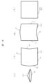
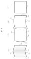
- FIG. 1 shows an example of the use form and configuration of a space-floating image display device according to one embodiment.
- FIG. 1 (A) shows the overall configuration of the space-floating image display device according to this embodiment.
- a show window (window glass) 105 which is a light-transmitting member (also described as a transparent member) such as glass, divides the space.
- a transparent member such as glass
- FIG. 1 (A) shows a case where the back side of the window glass 105 in the depth direction is the store space and the front side is the outside store space (e.g., the sidewalk).
- a means for reflecting a specific polarized wave such as an optical component
- the image display device 1 includes an image display unit 1a that displays the original image of the floating image 3, an image control unit 1b that converts the input image to match the resolution of the panel of the image display unit 1a, an image signal receiving unit 1c that receives an image signal, and a receiving antenna 1d.
- the image signal receiving unit 1c is compatible with wired input signals such as USB (Universal Serial Bus: registered trademark) input and HDMI (High-Definition Multimedia Interface: registered trademark) input, and wireless input signals such as Wi-Fi (Wireless Fidelity: registered trademark).
- the image display device 1 can function independently as an image receiving and display device, and can also display image information from an external PC, tablet, smartphone, etc. Furthermore, if a stick PC or the like is connected, the image display device 1 can be equipped with capabilities such as calculation processing and image analysis processing.
- FIG. 2A shows an example of the configuration of the main part of a space floating image display device according to an embodiment.
- the embodiment of FIG. 2A shows a configuration in which an image display device 1 and a retroreflective member (in other words, a retroreflective plate) 2 are arranged in a substantially V-shape (hereinafter, referred to as a V-shape).
- a V-shape a substantially V-shape
- an image display device 1 that generates image light of a specific polarization is provided in an oblique direction (a direction corresponding to an optical axis A1) relative to a transparent member 100 such as flat glass (arranged horizontally in this example).
- a retroreflective member 2 is provided in another oblique direction (a direction corresponding to an optical axis A2) relative to the transparent member 100 such as flat glass.
- the image display device 1 is composed of a light source device 13, a liquid crystal display panel 11 which is a liquid crystal display element, an absorbing polarizing plate 12, and the like.
- image light of a specific polarization emitted from the liquid crystal display panel 11 of the image display device 1 travels in the direction of optical axis A1, is reflected by a beam splitter 101 (polarization separation member) having a film that selectively reflects image light of a specific polarization provided on a transparent member 100, travels in the direction of optical axis A2, and is incident on the retroreflective member 2.
- the beam splitter 101 is formed in a sheet shape and adhered to the underside of the transparent member 100 such as flat glass.
- the beam splitter 101 may be formed by evaporating an optical thin film directly onto the flat glass.
- the image light incidence surface (in other words, the retroreflective surface) of the retroreflective member 2 is provided with a ⁇ /4 plate 21.
- the ⁇ /4 plate 21 is a polarization conversion element, a phase difference plate, and a quarter-wave plate.
- the image light on the optical axis A2 from the beam splitter 101 is passed through the ⁇ /4 plate 21 twice, once when it enters the retroreflective member 2 and once when it leaves the retroreflective member 2, and is polarized and converted from a specific polarization (one polarized wave) to the other polarized wave.
- the beam splitter 101 which selectively reflects the image light of a specific polarization, has the property of transmitting the image light of the other polarized wave after the polarization conversion. Therefore, the image light of the other polarized wave after the polarization conversion passes through the beam splitter 101.
- the image light that passes through the beam splitter 101 forms and displays the real image, the floating image 3, at a predetermined position outside the transparent member 100 in the direction of the optical axis A3 corresponding to the optical axis A2.
- the light that forms the floating image 3 is a collection of light rays that converge from the retroreflective member 2 to the optical image of the floating image 3, and these light rays continue to travel in a straight line even after passing through the optical image of the floating image 3. Therefore, in the configuration of FIG. 2A, when a user views the floating image 3 from direction A, which corresponds to the optical axis A3, the floating image 3 is seen as a bright image. However, when viewed by another person from direction B, for example, as shown by the arrow, the floating image 3 cannot be seen as an image at all. These characteristics are extremely suitable for use in systems that display images that require high security or highly confidential images that should be concealed from people directly facing the user.
- the polarization axis of the reflected image light may become misaligned.
- a portion of the image light with a misaligned polarization axis is reflected by the beam splitter 101 described above and returns to the image display device 1.
- This returned light may be re-reflected on the image display surface of the liquid crystal display panel 11 constituting the image display device 1, generating a ghost image and possibly degrading the image quality of the floating image 3. Therefore, in this embodiment, an absorbing polarizing plate 12 is provided on the image display surface of the image display device 1.
- the image light emitted from the image display device 1 is transmitted through the absorbing polarizing plate 12, and the reflected light returning from the beam splitter 101 is absorbed by the absorbing polarizing plate 12. This makes it possible to suppress the re-reflection and prevent degradation of image quality due to ghost images of the floating image 3.
- the above-mentioned beam splitter (polarization separation member) 101 is formed, for example, from a reflective polarizing plate or a metal multilayer film that reflects a specific polarized wave. More specifically, the beam splitter 101 can be formed by evaporating an optical thin film onto flat glass (for example, quartz glass).
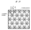
- Retroreflective member 2B shows an example of the surface shape of a retroreflector as a representative retroreflective member 2.
- a light ray incident on the interior of regularly arranged triangular pyramid prisms is reflected by three walls and a bottom surface of the triangular pyramid prism and is emitted as retroreflected light in a direction corresponding to the incident light, and a real image floating in space is displayed based on the image displayed on the display device 1.
- the resolution of this floating image 3 depends heavily on the outer diameter D and pitch P of the retroreflective area 2a (area surrounded by a hexagon) of the retroreflective member 2 shown in FIG. 2B, in addition to the resolution of the liquid crystal display panel 11.
- the resolution of the liquid crystal display panel 11 depends heavily on the outer diameter D and pitch P of the retroreflective area 2a (area surrounded by a hexagon) of the retroreflective member 2 shown in FIG. 2B, in addition to the resolution of the liquid crystal display panel 11.
- the effective resolution of the floating image 3 is reduced to about 1/3.
- the diameter D and pitch P of the retroreflective area 2a closer to one pixel of the liquid crystal display panel 11.
- the pitch ratio of each it is advisable to design the pitch ratio of each to be a different integer multiple of one pixel. Also, it is advisable to arrange the shape so that none of the sides of the retroreflective region 2a overlaps with any of the sides of one pixel of the liquid crystal display panel 11.
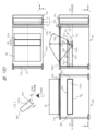
- FIG. 3 shows an example of the configuration of the main parts of a space floating image display device according to an embodiment, which is different from the embodiment of Fig. 2A.
- the embodiment of Fig. 3 shows a configuration in which an image display device 1 and a retroreflective member 2 (retroreflective plate) are arranged opposite each other, and a beam splitter 101 is arranged in the space connecting them at an angle of about 45 degrees to the image display device 1 and the retroreflective member 2, roughly in a Z shape (or inverted Z shape) (hereinafter referred to as Z shape).
- Z shape or inverted Z shape
- the Z-shaped configuration shown in FIG. 3 includes a transparent member 100 such as a glass plate and an absorbing polarizer 112 for the purpose of reducing the effect of external light incident from direction C on the retroreflective member 2 and image display device 1.
- the image display device 1 and the retroreflective member 2 are disposed at an angle of about 90 degrees to the transparent member 100 and the absorbing polarizer 112, and at an angle of about 45 degrees to the beam splitter 101.
- the beam splitter 101 is disposed horizontally, and the position of the image displayed on the image display device 1, more specifically the liquid crystal display panel 11, and the position where the floating image 3 is formed are plane-symmetrical to the beam splitter 101.
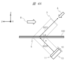
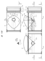
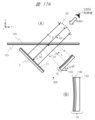
- FIG. 4A Another example of the optical system of the space floating image display device will be described with reference to FIG. 4A.
- the optical system of FIG. 4A is an optical system using a retroreflector 5 different from the retroreflector 2 used in FIG. 2A, FIG. 2B, and FIG. 3.
- FIG. 4F another example of the optical system will be described in more detail with reference to FIG. 4A to FIG. 4F.
- the components with the same reference numerals as those in FIG. 2A, FIG. 2B, and FIG. 3 have the same functions and configurations as those in FIG. 2A, FIG. 2B, and FIG. 3. Such components will not be described repeatedly in order to simplify the explanation.
- FIG. 4A is a diagram showing an example of the main components and retroreflective components of a spatial floating image display device according to one embodiment of the present invention.
- a display device 10 that emits image light is provided in an oblique direction of a transparent member 100 such as glass.
- the display device 10 includes a liquid crystal display panel 11 and a light source device 13 that generates light.
- the chief ray 9020 which represents the light beam emitted from the display device 10, travels toward the retroreflector 5 and is incident on the retroreflector 5 at an incident angle ⁇ .
- the incident angle ⁇ may be, for example, 45°.
- the incident angle ⁇ is not limited to 45°, and may be, for example, 45° ⁇ 15°.
- the retroreflector 5 is an optical element that has the optical property of retroreflecting light rays in at least some directions.
- the retroreflector 5 may also be referred to as an imaging optical element or imaging optical plate.
- the retroreflector 5 causes the main ray 9020 to travel in the z direction while being retroreflected in the x and y directions.
- the reflected ray 9021 travels along an optical path that is mirror-symmetrical to the main ray 9020 with the retroreflector 5 as the reference, in a direction away from the retroreflector 5, passes through the transparent member 100, and forms the floating-in-space image 3 as a real image on the imaging plane.
- the light beam that forms the floating image 3 is a collection of light rays that converge from the retroreflector 5 to the optical image of the floating image 3, and these light rays continue to travel in a straight line even after passing through the optical image of the floating image 3. Therefore, the floating image 3 is an image with high directionality, unlike a diffuse image formed on a screen by a general projector or the like. Therefore, in the configuration of FIG. 4A, when a user views the floating image 3 from the direction of arrow A, the floating image 3 is seen as a bright image. However, when another person views the floating image 3 from the direction of arrow B, the floating image 3 cannot be seen as an image at all. This characteristic is suitable for use in a system that displays images that require high security or highly confidential images that should be kept secret from people directly facing the user.
- the retroreflector 5 is configured by arranging multiple corner reflectors 9040 in an array on the surface of a transparent member. This may be called a corner reflector array or a multi-surface reflector array.
- the specific configuration of the corner reflector 9040 will be described in detail with reference to Figures 4D, 4E, and 4F.
- the light rays 9111, 9112, 9113, and 9114 emitted from the light source 9110 are reflected twice by the two mirror surfaces 9041 and 9042 of the corner reflector 9040, becoming reflected light rays 9121, 9122, 9123, and 9124.
- this double reflection is a retroreflection that turns back in the same direction as the incident direction (travels in a direction rotated 180 degrees), and in the z direction, it is a regular reflection in which the angle of incidence and the angle of reflection match due to total reflection.
- the light rays 9111 to 9114 generate reflected light rays 9121 to 9124 on a straight line symmetrical in the z direction with respect to the corner reflector 9040, forming an aerial real image 9120.
- the light rays 9111 to 9114 emitted from the light source 9110 are four light rays that represent the diffused light from the light source 9110, and although the light rays that enter the retroreflector 5 are not limited to these depending on the diffusion characteristics of the light source 9110, all of the incident light rays cause similar reflections and form an aerial real image 9120.
- the position of the light source 9110 and the position of the aerial real image 9120 in the x direction are shifted, but in reality the position of the light source 9110 and the position of the aerial real image 9120 in the x direction are the same, and are overlapping when viewed from the z direction.
- the corner reflector 9040 is a rectangular parallelepiped with only two specific faces being mirror surfaces 9041 and 9042, and the other four faces being made of transparent material.
- the retroreflector 5 has a configuration in which the corner reflectors 9040 are arrayed so that the corresponding mirror surfaces face in the same direction.
- mirror surface 9041 When viewed from the top (+z direction), light ray 9111 emitted from light source 9110 is incident on mirror surface 9041 (or mirror surface 9042) at a specific angle of incidence, is totally reflected at reflection point 9130, and is then totally reflected again at reflection point 9132 on mirror surface 9042 (or mirror surface 9041).
- the angle of incidence of light ray 9111 with respect to mirror surface 9041 (or mirror surface 9042) is ⁇
- the angle of incidence of the first reflected light ray 9131 reflected by mirror surface 9041 (or mirror surface 9042) with respect to mirror surface 9042 (or mirror surface 9041) can be expressed as 90°- ⁇ . Therefore, with respect to light ray 9111, the second reflected light ray 9121 rotates by 2 ⁇ after the first reflection and by 2 ⁇ (90°- ⁇ ) after the second reflection, resulting in a total inversion optical path of 180°.
- total reflection in the z direction occurs only once. Therefore, if the angle of incidence with respect to mirror surface 9041 or mirror surface 9042 is ⁇ , the reflected light ray 9121 rotates by 2 ⁇ after one reflection with respect to light ray 9111.
- the light rays incident on the corner reflector 9040 undergo retroreflection with inverted optical paths in the x and y directions, and undergo regular reflection due to total reflection in the z direction.
- the retroreflector 5 Similar reflections occur in each optical path, so that an image is formed at a point symmetrical with respect to the z-axis direction due to the inverted optical paths that are convergent in the x and y directions.
- the retroreflector 2 has retroreflection properties in three axial directions.
- the reflected light beam with convergence travels towards the side of the retroreflector 2 where the light source of the incident light is located.
- This reflected light beam with convergence forms an image in the air to form a floating image 3.
- the traveling direction of the chief ray of the reflected light beam with convergence reflected from the retroreflector 2 is the opposite direction to the traveling direction of the chief ray of the incident light beam with diffusivity that is incident on the retroreflector 2.
- the retroreflector 5 has retroreflection properties in two axial directions, and is specular in the other axial direction.
- the retroreflector 5 when a diffusive incident light beam is incident on the retroreflector 5, the convergent reflected light beam reflected by the corner reflector array travels toward the side of the retroreflector 5 opposite to the side where the light source of the incident light is located. This convergent reflected light beam forms an image in the air, forming the floating image 3.
- the direction of travel of the chief ray of the convergent reflected light beam reflected by the corner reflector array of the retroreflector 5 is not the opposite direction to the direction of travel of the chief ray of the diffusive incident light beam incident on the retroreflector 5.
- the normal component of the plate-shaped surface of the retroreflector 5 in the direction of travel of the chief ray of the diffusive incident light beam incident on the retroreflector 5 and the normal component of the plate-shaped surface of the retroreflector 5 in the direction of travel of the chief ray after being reflected by the retroreflector 5 to become a convergent reflected light beam continue to travel in a straight line before and after reflection by the corner reflector array.
- the diffusive incident light beam is converted into a convergent reflected light beam by reflection on the retroreflector 5, but in the normal direction to the plate-shaped surface of the retroreflector 5, this light beam travels as if passing through the retroreflector 5.
- the diffusive incident light beam that enters the retroreflector 5 and the convergent reflected light beam that exits from the retroreflector 5 are geometrically symmetrical with respect to the plate-shaped surface of the retroreflector 5.
- the surface shape of the retroreflector of this embodiment is not limited to the above example. It may have various surface shapes that realize retroreflection. Specifically, the surface of the retroreflector of this embodiment may be provided with retroreflection elements in which triangular pyramid prisms, hexagonal pyramid prisms, other polygonal prisms, or combinations of these are periodically arranged. Alternatively, the surface of the retroreflector of this embodiment may be provided with retroreflection elements in which these prisms are periodically arranged to form cube corners. These can also be expressed as corner reflector arrays and multifaceted reflector arrays. Alternatively, the surface of the retroreflector of this embodiment may be provided with capsule lens-type retroreflection elements in which glass beads are periodically arranged.
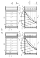
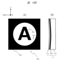
- the inventors have experimentally determined the relationship between the amount of blur l (small L) and the pixel size L (large L) of the image of the floating image 3 that is acceptable for improving visibility by creating an image display device 1 that combines a liquid crystal display panel 11 with a pixel pitch of 40 ⁇ m and a light source device 13 with a narrow divergence angle (divergence angle of 15°) of this embodiment.
- Figure 5 shows the experimental results. It was found that the amount of blur l that deteriorates visibility is preferably 40% or less of the pixel size, and is barely noticeable if it is 15% or less.
- the surface roughness of the reflective surface at which this amount of blur l is acceptable is an average roughness of 160 nm or less within a measurement distance of 40 ⁇ m, and it was found that to achieve a less noticeable amount of blur l, the surface roughness of the reflective surface is preferably 120 nm or less. For this reason, it is desirable to reduce the surface roughness of the retroreflective member 2 described above, and to keep the surface roughness of the reflective film and its protective film that form the reflective surface below the above-mentioned value.
- a roll press method for molding involves aligning the retroreflective members 2a and shaping them on a film.
- the inverse shape of the shape to be shaped is formed on the surface of a roll, an ultraviolet-curable resin is applied onto a base material for fixing, and the required shape is formed by passing it between the rolls, and then the desired shape is obtained by irradiating ultraviolet light to harden it.
- the image display device 1 of this embodiment uses a liquid crystal display panel 11 and a light source device 13 (see FIG. 6 for details) as a light source that generates light of a specific polarization, which reduces the possibility of image light being incident obliquely on the retroreflective member 2 described above. As a result, the occurrence of ghost images is suppressed, and even if a ghost image does occur, the brightness of the ghost image is low, resulting in a structurally excellent system.
- the image display device 1 which is configured with a liquid crystal display panel 11, an absorptive polarizer 12, and a light source device 13, is disposed at a predetermined angle (for example, an angle of about 45 degrees with respect to the beam splitter 101 in the horizontal plane).
- the image light from the image display device 1 passes through the beam splitter 101 in the direction of optical axis B1 (diagonal direction with respect to the beam splitter 101), and proceeds toward the retroreflective member 2 in the direction of optical axis B2 (corresponding to direction D) that corresponds to the optical axis B1.
- the image light from the image display device 1 is image light having the characteristics of a specific polarization, for example, P-polarized (parallel polarization).
- the beam splitter 101 is a polarization separation member such as a reflective polarizing plate, and has the property of transmitting P-polarized image light from the image display device 1 but reflecting S-polarized (vertical polarization) image light.
- This beam splitter 101 is formed from a reflective polarizing plate or a metal multilayer film that reflects specific polarization.
- This beam splitter 101 can generally be formed by evaporating an optical thin film onto a flat glass substrate. Therefore, the refractive index of the beam splitter 101 has substantially the same value as the refractive index n (n ⁇ 1.5) of flat glass.
- a ⁇ /4 plate 21 is provided on the light incidence surface (retroreflective surface) of the retroreflective member 2.
- the P-polarized image light transmitted through the beam splitter 101 from the image display device 1 is polarized and converted from P-polarized to S-polarized light by passing through the ⁇ /4 plate 21 twice in total when it enters and leaves the retroreflective member 2.
- the S-polarized image light after polarization conversion from the retroreflective member 2 is reflected by the beam splitter 101 and travels toward the transparent member 100, etc.
- the S-polarized image light that travels in a direction corresponding to the optical axis B3 after reflection (diagonal direction with respect to the beam splitter 101) passes through the transparent member 100 made of a glass plate or the like and the absorbing polarizing plate 112, and generates and displays the real image, which is a floating image 3, at a predetermined position outside the transparent member 100, etc.
- the retroreflective member 2 in order to reduce degradation of image quality caused by sunlight or illumination light entering an optical system composed of optical components such as the image display device 1, the retroreflective member 2, and the beam splitter 101, it is advisable to provide an absorptive polarizing plate 112 on the outer surface of the transparent member 100. Since the polarization axis may become uneven due to the retroreflective member 2 reflecting light, some of the image light may be reflected by the beam splitter 101 and returned to the image display device 1. This returned light is reflected again by the image display surface of the liquid crystal display panel 11 constituting the image display device 1, generating a ghost image and significantly degrading the image quality of the floating image 3 in space.
- an absorptive polarizer 12 is provided on the image display surface of the image display device 1.
- an anti-reflection film (not shown) may be provided on the image output side of the absorptive polarizer 12 provided on the surface of the image display device 1. In this way, the light that causes the ghost image to be generated is absorbed by the absorptive polarizer 12, thereby preventing degradation of image quality due to the ghost image of the floating image 3 in space.
- the retroreflective member 2 is tilted downward with respect to the direction of incidence of the external light to prevent the incidence of the external light.
- the main incident direction of the external light is set to a direction (diagonal direction like the optical axis B3) corresponding to the direction C indicated by the arrow (the direction in which the user views the floating image 3 from the front).
- the retroreflective member 2 is arranged so that the optical axis B2 is, for example, at an angle of about 90 degrees with respect to the direction C (optical axis B3).
- the image display device 1 is also arranged in a different direction from the incident direction of the external light (direction C). Specifically, the main surface (image light exit surface) of the image display device 1 is arranged in the same direction (in other words, parallel) as the main surface of the retroreflective member 2, and the optical axis B1 of the image display device 1 is arranged at an angle of approximately 90 degrees to the optical axis B3 corresponding to the incident direction of the external light (direction C). Furthermore, when considering the range of the light flux when external light is incident on the main surface of the transparent member 100 functioning as an opening in direction C, the image display device 1 is arranged at a position slightly outside that range. This reduces the occurrence of ghost images caused by re-reflection at the image display device 1.
- FIG. 6 shows a configuration example of an image display device 1 applicable to the embodiments of Fig. 2A and Fig. 3.
- This image display device 1 is configured to include a light source device 13, a liquid crystal display panel 11, a light direction conversion panel 54, etc.
- the image output surface side of the liquid crystal display panel 11 may be provided with the above-mentioned absorptive polarizing plate 12.
- the light source device 13 is configured to include a plurality of LED elements 201 (LEDs: Light Emitting Diodes) which are semiconductor light sources (solid light sources) constituting the light source, a light guide 203, etc.
- Fig. 6 shows a developed perspective view of the state in which the liquid crystal display panel 11 and the light direction conversion panel 54 are arranged on the light output side of the light source device 13.
- the light source device 13 is formed, for example, from a plastic case (not shown) and is configured to house the LED elements 201 and the light guide 203 inside.
- a light receiving end surface 203a is provided on the light incident side of the light guide 203 to convert the divergent light from each LED element 201 into a substantially parallel beam.
- the light receiving end surface 203a has a shape in which the cross-sectional area gradually increases toward the opposite side to the light receiving portion, and is provided with a lens shape that has the effect of gradually decreasing the divergence angle by multiple total reflections as the light propagates inside.
- the liquid crystal display panel 11 is attached to the upper surface of the light guide 203, and is disposed approximately parallel to the light guide 203.
- the upper surface of the light guide 203 serves as an emission surface that emits light reflected by the light guide 203.
- a plurality of LED elements 201 are attached to one side (the lower side in FIG. 6) of the case of the light source device 13. The light from the plurality of LED elements 201 is converted into approximately collimated light (approximately parallel light) by the shape of the light receiving end surface 203a of the light guide 203. For this reason, the light receiving portion of the light receiving end surface 203a and the LED elements 201 are attached while maintaining a predetermined positional relationship.
- the light source device 13 is configured by attaching a light source unit in which a plurality of LED elements 201 serving as light sources are arranged to the light receiving end surface 203a, which is a light receiving section provided on the light incident side of the light guide 203.
- the divergent light beam from the LED elements 201 is made into approximately collimated light by the lens shape of the light receiving end surface 203a of the light guide 203. This approximately collimated light is guided inside the light guide 203 in the direction A indicated by the arrow.
- the direction A is approximately parallel to the liquid crystal display panel 11 (from bottom to top in the drawing).
- the light guided in the direction A has its light beam direction converted by the light beam direction conversion section 204 provided in the light guide 203, and is emitted in the direction B indicated by the arrow toward the liquid crystal display panel 11, which is approximately parallel to the light guide 203.
- the direction B is approximately perpendicular to the display surface of the liquid crystal display panel 11.
- the light guide 203 has a configuration in which the distribution (in other words, density) of the light beam direction conversion section 204 is optimized depending on the shape inside or on the surface of the light guide 203. This makes it possible to control the uniformity of the light, which is the light beam emitted from the light source device 13 shown in direction B and incident on the liquid crystal display panel 11.
- the directivity of the light in direction B from the light source device 13 can be controlled to improve the utilization efficiency of the light flux emitted from the light source device 13 shown in direction B and significantly reduce power consumption.
- a light source having a narrow divergence angle can be configured as the light source device 13.
- the image light from the image display device 1 reaches the observer efficiently with high directivity (in other words, linearity) like laser light, and a high-quality floating image can be displayed at high resolution.
- the power consumption by the image display device 1 including the LED elements 201 of the light source device 13 can be significantly reduced.
- the liquid crystal display panel 11 is attached to a frame (not shown) of the liquid crystal display panel 11, which is attached to the top surface of a case (not shown) of the light source device 13, and is configured by mounting the liquid crystal display panel 11 attached to the frame and a flexible printed circuit board (FPC: Flexible Printed Circuits) (not shown) electrically connected to the liquid crystal display panel 11.
- the liquid crystal display panel 11, which is a liquid crystal display element, generates a display image by modulating the intensity of transmitted light together with the LED elements 201 based on a control signal from a control circuit (not shown) that constitutes the electronic device.
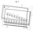
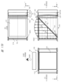
- FIG. 7 a table-top type floating image display device according to one embodiment will be described with reference to FIG. 7 and subsequent figures.
- the floating image display device according to each embodiment shown in FIG. 7 to FIG. 9 has a basic configuration similar to the V-shaped configuration shown in FIG. 2A.
- FIG. 7 shows an example of the configuration of the main parts of a space floating image display device 400 suitable for installation on a desk, according to one embodiment (hereinafter referred to as a first embodiment).
- FIG. 7 shows a cross-sectional view of the space-floating image display device 400 as seen from the side.
- the front of the device here corresponds to the direction in which the space-floating image 3 (3A, 3B) formed by the space-floating image display device 400 can be viewed from the front by the user (230A, 230B).
- Directions AA and AB are the directions in which the user views the floating image 3 (3A, 3B) from the front, and correspond to the negative direction in the Y direction.
- a coordinate system and directions such as (X, Y, Z) shown in the figure may be used.
- the Z direction is the vertical direction
- the X direction and the Y direction are two horizontal directions that intersect at right angles
- the X direction is the depth direction
- the front-to-back direction (the front-to-back horizontal direction within the screen of the floating image 3)
- the Y direction is the left-to-right direction (the left-to-right horizontal direction within the screen of the floating image 3).
- the basic configuration of the V-shaped structure in FIG. 7 is the same as that of the V-shaped structure in FIG. 2A in terms of the positional relationship of the components (image display device 1, beam splitter 101A and transparent member 100A, and retroreflective member 2, etc.).
- the image display device 1 includes a liquid crystal display panel 11 and a light source device 13.
- the beam splitter 101A and the transparent member 100A will be treated as one unit, and the transparent member will be abbreviated. Other similar components will also be abbreviated in the same way.
- the components of the floating-in-space image display device 400 are arranged with a predetermined positional relationship to each other. That is, the image display device 1, beam splitter 101A, retroreflective member 2, etc. in FIG. 7 are arranged with a predetermined positional relationship to form a V-shape, similar to the configuration in FIG. 2A.
- the formed floating-in-space image 3A can be viewed from the front by the user 230A in the direction AA.
- the first embodiment of the floating image display device 400 shown in FIG. 7 has a hinge mechanism 330 that serves as a rotation fulcrum at one end of the beam splitter 101A.
- the hinge mechanism 330 does not move up, down, left, or right, but is free to rotate. It is provided in the X direction at the left end of the beam splitter 101A, and the beam splitter 101A can rotate up and down around the hinge mechanism 330, which serves as a rotation fulcrum.
- the 7 has a display panel that displays an image, a polarizing separation member that reflects a portion of the image light emitted from the display panel, and a retroreflective member that retroreflects the reflected light from the polarizing separation member, and the reflected light reflected by the retroreflective member passes through the polarizing separation member to form a floating image, and the angle of the polarizing separation member with respect to the display panel and the retroreflective member is variable.
- the image display device 1 and the retroreflective member 2 are fixed in position, while the beam splitter 101A and the transparent member 100A can be positioned at different angles.
- the beam splitter 101A and the transparent member 100A can be rotated around the hinge mechanism 330 as a rotation fulcrum, changing the distance between the beam splitter 101A and the image display device 1, and the beam splitter 101A and the retroreflective member 2. Even if the angle at which the beam splitter 101A and the transparent member 100A are positioned is different, they are positioned in a positional relationship to form a V-shape, similar to the configuration in FIG. 2A.
- the beam splitter 101A and the transparent member 100A are rotated upward by an angle ⁇ with respect to the horizontal position (XY plane) using the hinge mechanism 330 as a rotation fulcrum, and placed at the position of the beam splitter 101B and the transparent member 100B.
- the image light from the image display device 1 passes through the optical axis AB1, which is longer than the optical axis A1, is reflected by the beam splitter 101B, passes through the ⁇ /4 plate 21 along the optical axis AB2, and enters the retroreflective member 2.
- the image light that is retroreflected by the retroreflective member 2 and emitted passes through the ⁇ /4 plate 21 again, where it is converted to the other polarization, and passes through the beam splitter 101B.
- the image light that passes through the beam splitter 101B forms and displays a real image, a floating-in-space image 3B, at a predetermined position outside the transparent member 100B in the direction of the optical axis AB3 that corresponds to the optical axis AB2.
- the formed floating-in-space image 3B can be viewed as a bright image by the user 230B in a frontal position from the direction AB indicated by the arrow that corresponds to the optical axis AB3.
- beam splitter 101B is positioned above beam splitter 101A by angle ⁇ , the length of optical axis AB1 from image display device 1 to beam splitter 101B is longer than optical axis A1 from image display device 1 to beam splitter 101A, and floating image 3B is formed at a higher position than floating image 3A. For this reason, when the height of the viewpoint position differs due to differences in height between users, it is possible to form floating image 3 at an easily visible position by changing the tilt angle of beam splitter 101.
- beam splitter 101A in a horizontal position forms a floating image 3A that is optimal for user 230A
- beam splitter 101B with an upward angle of ⁇ with respect to the horizontal position (XY plane) forms a floating image 3B that is optimal for user 230B, who is taller than user 230A.
- FIG. 8 shows a configuration example of a space floating image display device 400 suitable for installation on a desk, according to one embodiment (hereinafter referred to as a second embodiment).
- Figure 8 shows a cross-sectional view of the floating-in-space image display device 400 as seen from the side.
- the floating-in-space image display device 400 of the first embodiment in FIG. 7 is placed in a housing 4001, and the housing 4001 has an opening (opening hole) 4002 in the horizontal direction (parallel to the XY plane).
- the hinge mechanism 330 is provided at one end of the opening 4002, and rotatably holds the beam splitter 101A at one side of the beam splitter 101A opposite the user 230, and serves as a rotation fulcrum for the beam splitter 101A.
- the floating-in-space image display device 400 also includes a control unit 500 having control functions, an imaging unit 510, and a piston mechanism 310 that moves the piston up and down or expands and contracts.
- FIG. 8 the positional relationship of the components (image display device 1, beam splitter 101A and transparent member 100A, retroreflective member 2, etc.) is the same as that of the V-shaped configuration in FIG. 7. Note that, hereinafter, beam splitter 101A and transparent member 100A will be treated as one unit, and the transparent member will be abbreviated. Other similar components will also be abbreviated in the same way.
- the components of the floating-in-space image display device 400 are arranged with a predetermined positional relationship to each other. That is, the image display device 1, beam splitter 101A, retroreflective member 2, etc. in FIG. 8 are arranged with a predetermined positional relationship to form a V-shape, similar to the configuration in FIG. 7.
- the formed floating-in-space image 3A can be viewed from the front by the user 230A from the direction AA.
- this structure allows beam splitter 101A and transparent member 100A to be positioned at different angles while image display device 1 and retroreflective member 2 are fixed in position.
- this structure allows beam splitter 101A and transparent member 100A to be rotated around hinge mechanism 330 as a rotation fulcrum, changing the separation distance between beam splitter 101A and image display device 1, and the separation distance between beam splitter 101A and retroreflective member 2.
- a display panel that displays an image
- a polarization separation member that reflects a portion of the image light emitted from the display panel
- a retroreflective member that retroreflects the light reflected from the polarization separation member, and the light reflected by the retroreflective member passes through the polarization separation member to form a floating image, and the angle of the polarization separation member relative to the display panel and the retroreflective member is variable.
- Piston mechanism 310 is disposed on the side of beam splitter 101A and transparent member 100A that faces hinge mechanism 330.
- the piston of piston mechanism 310 In the initial state, the piston of piston mechanism 310 is in contact with one side of beam splitter 101A and transparent member 100A with the length of piston 310A, holding beam splitter 101A and transparent member 100A horizontally (parallel to the XY plane).
- piston 310A of piston mechanism 310 extends and is in the state of piston 310B
- beam splitter 101A and transparent member 100A rotate upward by angle ⁇ with respect to the horizontal position (XY plane) with hinge mechanism 330 as the rotation fulcrum, and move to the position of beam splitter 101B and transparent member 100B. That is, the piston mechanism 310 rotates the beam splitter 101A around the hinge mechanism 330 of the rotation axis, allowing the angle relative to the image display device 1 and the retroreflective member 2 to be changed.
- the image light from the image display device 1 passes through the optical axis AB1, which is longer than the optical axis A1, is reflected by the beam splitter 101B, passes through the ⁇ /4 plate 21 along the optical axis AB2, and enters the retroreflective member 2.
- the image light that is retroreflectively reflected by the retroreflective member 2 passes through the ⁇ /4 plate 21 again, is converted to the other polarization, and transmits the beam splitter 101B.
- the image light that transmits the beam splitter 101B forms and displays the real image, the floating image 3B, at a specified position outside the transparent member 100B, in the direction of the optical axis AB3 corresponding to the optical axis AB2.
- the formed floating image 3B can be viewed as a bright image by the user 230B in the front position from the direction AB indicated by the arrow corresponding to the optical axis AB3.
- the arrangement of the piston mechanism 310 is not limited to this embodiment, and similar effects can be obtained by arranging it on other sides of the beam splitter 101A and the transparent member 100A, or in multiple positions. Also, the method of rotating or driving the beam splitter 101A in the vertical direction with the hinge mechanism 330 as the rotation fulcrum is not limited to the piston mechanism 310.
- the imaging unit 510 captures images of the height, face, and facial components such as the eyes and mouth of the user 230, and information such as the height and face of the user 230 is input to the control unit 500.
- the imaging unit 510 detects, for example, the position of the eyes of the user 230 from the input information of the user 230, and obtains information on the height of the eyes of the user 230.
- control unit etc. 500 can drive the piston mechanism 310 to change the angle of the beam splitter 101A to a position optimal for the user 230's viewing.
- image capture unit 510 and control unit 500 control piston mechanism 310 so that beam splitter 101A holds the horizontal position.
- image capture unit 510 and control unit 500 extend piston 310A of piston mechanism 310 to piston 310B, and change the position of beam splitter 101A to that of beam splitter 101B tilted by angle ⁇ , allowing user 230B to view a bright image from a frontal position.
- FIG. 9 shows a configuration example of a space floating image display device suitable for installation on a desk, according to one embodiment (hereinafter referred to as a third embodiment).
- FIG. 9 shows a cross-sectional view of the floating-in-space image display device as seen from the side.
- the floating-in-space image display device 400 is disposed inside a housing 4001.
- FIG. 9 the positional relationships of the components (image display device 1, beam splitter 101A and transparent member 100A, retroreflective member 2, etc.) are the same as those of the V-shaped configuration in FIG. 2A.
- beam splitter 101A and transparent member 100A will be treated as a single unit, and the transparent member will be abbreviated.
- Other similar components will also be abbreviated in the same way.
- the components of the floating-in-space image display device are arranged with a predetermined positional relationship to each other. That is, the image display device 1, beam splitter 101A, retroreflective member 2, etc. in FIG. 9 are arranged with a predetermined positional relationship to form a V-shape, similar to the configuration in FIG. 2A.
- the formed floating-in-space image 3A can be viewed from the front by user 230A in direction AA.
- hinge mechanism 331 is provided near the center of opening 4002, rotatably holds both ends of beam splitter 101A at or near the center line of beam splitter 101A that is parallel to one side of beam splitter 101A facing user 230, and serves as a rotation fulcrum for beam splitter 101A.
- Hinge mechanism 331 does not move up, down, left, or right, but is free to rotate, and beam splitter 101A is structured to rotate up and down around hinge mechanism 331 as a rotation fulcrum.
- a display panel that displays an image
- a polarization separation member that reflects a portion of the image light emitted from the display panel
- a retroreflective member that retroreflects the light reflected from the polarization separation member, and the light reflected by the retroreflective member passes through the polarization separation member to form a floating image, and the angle of the polarization separation member relative to the display panel and the retroreflective member is variable.
- the image display device 1 and the retroreflective member 2 are fixedly arranged, while the beam splitter 101A and the transparent member 100A can be arranged at different angles.
- the beam splitter 101A and the transparent member 100A can be rotated around the hinge mechanism 331 as a rotation fulcrum, changing the distance between the beam splitter 101A and the image display device 1, and the beam splitter 101A and the retroreflective member 2. Even if the arrangement angle of the beam splitter 101A and the transparent member 100A is different, they are arranged with a positional relationship so as to form a V shape, similar to the configuration in FIG. 2A.
- the piston mechanism 310 is disposed on the side of the beam splitter 101A and the transparent member 100A facing the user 230.
- the piston of the piston mechanism 310 In the initial state, the piston of the piston mechanism 310 is in contact with one side of the beam splitter 101A and the transparent member 100A at the length of the piston 310A, and holds the beam splitter 101A and the transparent member 100A horizontally (parallel to the XY plane).
- the piston 310A of the piston mechanism 310 extends and is in the state of piston 310C
- the beam splitter 101A and the transparent member 100A rotate upward by an angle ⁇ with respect to the horizontal position (XY plane) around the hinge mechanism 331 as the rotation fulcrum, and move to the position of the beam splitter 101C and the transparent member 100C.
- the piston mechanism 310 rotates the beam splitter 101A around the hinge mechanism 331 of the rotation axis as the rotation fulcrum, and the angle with respect to the image display device 1 and the retroreflective member 2 can
- the image light from the center position of the image display device 1 is reflected or passes along the optical axes A1, A2, and A3 on the rotation fulcrum axis (X-axis direction) of the hinge mechanism 331 of the beam splitter 101A.
- the beam splitter 101A and the transparent member 100A rotate by an angle and the image light from the center position of the image display device 1 reaches the position of the beam splitter 101C and the transparent member 100C, the path and length of the optical path is almost unchanged, so the image light is reflected by the beam splitters 101A and 101C, passes through the ⁇ /4 plate 21 along the optical axis A2, and enters the retroreflective member 2.
- the image light that is retroreflected by the retroreflective member 2 passes through the ⁇ /4 plate 21 again and is converted to the other polarized wave, and then passes through the beam splitters 101A and 101C.
- the image light that passes through the beam splitters 101A and 101C generates a real image, a floating image, at a predetermined position outside the transparent members 100A and 100C in the direction of the optical axis A3 that corresponds to the optical axis A2, and the floating images are generated at approximately the same position, so that the floating images 3A and 3C almost overlap.
- the image light of the optical axis A11 at the lower end of the image display device 1 is reflected by the beam splitter 101C, passes through the ⁇ /4 plate 21 along the optical axis C12, and enters the retroreflective member 2.
- the image light that is retroreflected by the retroreflective member 2 passes through the ⁇ /4 plate 21 again, is converted to the other polarized wave, and transmits through the beam splitter 101C.
- the image light that has transmitted through the beam splitter 101C generates a real image, a floating image 3C, at a predetermined position outside the transparent member 100C in the direction of the optical axis C13 corresponding to the optical axis C12.
- the distance between the bottom end of the image display device 1 and the beam splitter 101C becomes shorter than the distance between the image display device 1 and the beam splitter 101A due to the rotation of the angle ⁇ , in other words the optical path distance becomes shorter, so that the position of the top end (left end in FIG. 9) of the generated floating-in-space image 3C becomes lower than the position of the top end of the floating-in-space image 3A.
- the image light of the optical axis A21 of the top end (right end in FIG. 9) of the image display device 1 is reflected by the beam splitter 101A, it passes through the ⁇ /4 plate 21 along the optical axis A22 and enters the retroreflective member 2.
- the image light that is retroreflected by the retroreflective member 2 and emitted passes through the ⁇ /4 plate 21 again, is converted into the other polarized wave, and transmits through the beam splitter 101A.
- the image light transmitted through the beam splitter 101A generates a real image, a floating image 3A, at a predetermined position outside the transparent member 100A in the direction of optical axis A23, which corresponds to optical axis A22.
- the image light of the optical axis A21 at the upper end of the image display device 1 is reflected by the beam splitter 101C, passes through the ⁇ /4 plate 21 along the optical axis C22, and enters the retroreflective member 2.
- the image light that is retroreflected by the retroreflective member 2 passes through the ⁇ /4 plate 21 again, is converted to the other polarized wave, and transmits through the beam splitter 101C.
- the image light that has transmitted through the beam splitter 101C generates a real image, a floating image 3C, at a predetermined position outside the transparent member 100C in the direction of the optical axis C23 corresponding to the optical axis C22.
- the distance between the top of the image display device 1 and the beam splitter 101C becomes longer than the distance between the image display device 1 and the beam splitter 101A due to the rotation of the angle ⁇ , in other words the optical path distance becomes longer, so that the bottom end (left end in FIG. 9) of the generated floating-in-space image 3C becomes higher than the top end of the floating-in-space image 3A.
- floating image 3C is tilted counterclockwise more than floating image 3A, or the tilt angle of floating image 3C occurs at a shallower angle closer to the horizontal plane than floating image 3A.
- Floating image 3C can be seen as a bright floating image in front of user 230C, who is taller or has a higher viewpoint than user 230A, in the direction AC indicated by the arrow.
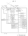
- FIG. 10 is a block diagram showing an example of the internal configuration of the space-floating image display device 400.
- the space-floating image display device 400 includes a retroreflective member 2, a liquid crystal display panel 11, a light guide 203, a light source device 13, a power source 1106, an external power source input interface 1111, an operation input unit 1107, a non-volatile memory 1108, a memory 1109, a control unit 1110, a video signal input unit 1131, an audio signal input unit 1133, a communication unit 1132, an aerial operation detection sensor 1351, an aerial operation detection unit 1350, an audio output unit 1140, a video control unit 1160, a storage unit 1170, an imaging unit 510, a beam splitter 101, a beam splitter angle adjustment unit 1010, and the like.
- the beam splitter angle adjustment unit 1010 includes the piston mechanism 310 shown in Figures 8 and 9, and adjusts the angle of the beam splitter 101 relative to the image display device 1 and the retroreflective member 2.
- a removable media interface 1134 may also be included.
- a position sensor 1113 may also be included.
- a transmissive self-luminous image display device may also be included.
- the components of the space floating image display device 400 are arranged in a housing 4001.
- the imaging unit 510 and the aerial operation detection sensor 1351 may be provided on the outside of the housing 4001.
- the retroreflective member 2 retroreflects the light modulated by the liquid crystal display panel 11.
- the light reflected from the retroreflective member 2 is output to the outside of the spatial floating image display device 400 to form the spatial floating image 3.
- the liquid crystal display panel 11 is a display unit that generates an image by modulating transmitted light based on an input video signal under the control of the video control unit 1160 described below.
- a transmissive liquid crystal panel is used.
- a reflective liquid crystal panel that modulates reflected light or a DMD (Digital Micromirror Device: registered trademark) panel may be used.
- the light source device 13 supplies light to the liquid crystal display panel 11 and is a solid-state light source such as an LED light source or a laser light source.
- the power supply 1106 converts AC current input from the outside via the external power supply input interface 1111 into DC current and supplies power to the light source device 13.
- the power supply 1106 also supplies the necessary DC current to each part within the space floating image display device 400.
- the secondary battery 1112 stores the power supplied from the power source 1106. Furthermore, when power is not supplied from the outside via the external power input interface 1111, the secondary battery 1112 supplies power to the light source device 13 and other components that require power. In other words, when the space floating image display device 400 is equipped with the secondary battery 1112, the user can use the space floating image display device 400 even when power is not supplied from the outside.
- the light guide 203 guides the light generated by the light source device 13 and irradiates it onto the liquid crystal display panel 11.
- the combination of the light guide 203 and the light source device 13 can also be called the backlight of the liquid crystal display panel 11.
- the light guide 203 may be configured mainly using glass.
- the light guide 203 may be configured mainly using plastic.
- the light guide 203 may be configured using a mirror. There are various possible methods for combining the light guide 203 with the light source device 13.
- the aerial operation detection sensor 1351 is a sensor that detects the operation of the floating-in-space image 3 by the finger of the user 230.
- the aerial operation detection sensor 1351 senses, for example, the entire display range of the floating-in-space image 3 and the range that overlaps with it.
- the aerial operation detection sensor 1351 may sense only a range that overlaps with at least a portion of the display range of the floating image 3. Specific examples of the aerial operation detection sensor 1351 include distance sensors that use invisible light such as infrared rays, invisible light lasers, ultrasonic waves, etc. The aerial operation detection sensor 1351 may also be configured to detect coordinates on a two-dimensional plane by combining multiple sensors. The aerial operation detection sensor 1351 may also be configured with a ToF (Time of Flight) type LiDAR (Light Detection and Ranging) or an image sensor.
- ToF Time of Flight
- LiDAR Light Detection and Ranging
- the mid-air operation detection sensor 1351 only needs to be capable of sensing to detect touch operations, etc., performed by the user with his/her finger on an object displayed as the floating-in-space image 3. Such sensing can be performed using existing technology.
- the aerial operation detection unit 1350 acquires a sensing signal from the aerial operation detection sensor 1351, and performs operations such as determining whether the finger of the user 230 has touched an object in the floating-in-space image 3 and calculating the position (contact position) where the finger of the user 230 has touched the object based on the sensing signal.
- the aerial operation detection unit 1350 is configured with a circuit such as an FPGA (Field Programmable Gate Array). Some of the functions of the aerial operation detection unit 1350 may be realized by software, for example, by a spatial operation detection program executed by the control unit 1110.
- the aerial operation detection sensor 1351 and the aerial operation detection unit 1350 may be configured to be built into the space-floating image display device 400, or may be provided separately from the space-floating image display device 400. When provided separately from the space-floating image display device 400, the aerial operation detection sensor 1351 and the aerial operation detection unit 1350 are configured to transmit information and signals to the space-floating image display device 400 via a wired or wireless communication connection path or image signal transmission path.
- the aerial operation detection sensor 1351 and the aerial operation detection unit 1350 may be provided separately. This makes it possible to build a system in which the main body is the floating-in-space image display device 400, which does not have an aerial operation detection function, and only the aerial operation detection function can be added as an option.
- the aerial operation detection sensor 1351 alone may be a separate component, and the aerial operation detection unit 1350 may be built into the space-floating image display device 400.
- the aerial operation detection sensor 1351 alone may be a separate component, and the aerial operation detection unit 1350 may be built into the space-floating image display device 400.
- the imaging unit 510 is a camera with an image sensor, and captures images of the face, eyes, arms, fingers, and/or the space near the floating image 3 of the user 230.
- the information on the face and eyes of the user 230 captured by the imaging unit 510 is used by the beam splitter angle adjustment unit 1010 to detect the position of the face and eyes of the user 230 and obtain height information. If the obtained height information differs from the pre-determined viewing height, the beam splitter angle adjustment unit 1010 can drive the piston mechanism 310 to change the angle of the beam splitter 101 to a position optimal for viewing by the user 230.
- a plurality of imaging units 510 may be provided. By using a plurality of imaging units 510, or by using an imaging unit with a depth sensor, the aerial operation detection unit 1350 can be assisted in the detection process of the touch operation of the user 230 on the floating-in-space image 3.
- the imaging unit 510 may be provided separately from the floating-in-space image display device 400. When the imaging unit 510 is provided separately from the floating-in-space image display device 400, it is sufficient to configure it so that an imaging signal can be transmitted to the floating-in-space image display device 400 via a wired or wireless communication connection path or the like.
- the aerial operation detection sensor 1351 may not be able to detect information such as how far an object that has not intruded into the intrusion detection plane (for example, a user's finger) is from the intrusion detection plane, or how close the object is to the intrusion detection plane.
- the distance between the object and the intrusion detection plane can be calculated by using information such as object depth calculation information based on the images captured by the multiple imaging units 510 and object depth information from a depth sensor.
- This information as well as various information such as the distance between the object and the intrusion detection plane, are used for various display controls for the floating-in-space image 3.
- the mid-air operation detection unit 1350 may detect touch operations on the floating-in-space image 3 by the user 230 based on the images captured by the imaging units 510.
- the imaging unit 510 may also capture an image of the face of the user 230 operating the floating image 3, and the control unit 1110 may perform an identification process for the user 230.
- the imaging unit 510 may also capture an image of the user 230 operating the floating image 3 and the surrounding area of the user 230 in order to determine whether or not another person is standing around or behind the user 230 operating the floating image 3 and peeking at the user's operation of the floating image 3.
- the operation input unit 1107 is, for example, an operation button, a signal receiving unit such as a remote controller, or an infrared light receiving unit, and inputs a signal for an operation different from the aerial operation (touch operation) by the user 230.
- the operation input unit 1107 may be used, for example, by an administrator to operate the floating-in-space image display device 400.
- Video signal input unit 1131 connects to an external video output device and inputs video data.
- Various digital video input interfaces are possible for video signal input unit 1131.
- it may be configured with a video input interface conforming to the HDMI (registered trademark) (High-Definition Multimedia Interface) standard, a video input interface conforming to the DVI (Digital Visual Interface) standard, or a video input interface conforming to the DisplayPort standard.
- an analog video input interface such as analog RGB or composite video may be provided.
- the audio signal input unit 1133 is connected to an external audio output device and inputs audio data.
- the audio signal input unit 1133 may be configured with an HDMI standard audio input interface, an optical digital terminal interface, or a coaxial digital terminal interface, etc.
- the video signal input unit 1131 and the audio signal input unit 1133 may be configured as an interface in which the terminals and cables are integrated.
- the audio output unit 1140 is capable of outputting audio based on the audio data input to the audio signal input unit 1133.
- the audio output unit 1140 may be configured as a speaker.
- the audio output unit 1140 may also output built-in operation sounds and error warning sounds.
- the audio output unit 1140 may be configured to output a digital signal to an external device, such as the Audio Return Channel function defined in the HDMI standard.
- Non-volatile memory 1108 stores various data used by the space floating image display device 400.
- Data stored in non-volatile memory 1108 includes, for example, data for various operations to be displayed on the space floating image 3, display icons, data for objects to be operated by the user, layout information, etc.
- Memory 1109 stores image data to be displayed as the space floating image 3, data for controlling the device, etc.
- the control unit 1110 controls the operation of each connected unit.
- the control unit 1110 may also work with a program stored in the memory 1109 to perform calculations based on information acquired from each unit in the space floating image display device 400.
- the communication unit 1132 communicates with external devices, external servers, etc., via a wired or wireless communication interface.
- the wired communication interface may be configured, for example, as an Ethernet standard LAN interface.
- the interface may be configured, for example, as a Wi-Fi communication interface, a Bluetooth communication interface, or a mobile communication interface such as 4G or 5G.
- Various types of data such as video data, image data, and audio data, are sent and received by communication via the communication unit 1132.
- the removable media interface 1134 is an interface for connecting a removable recording medium (removable media).
- the removable recording medium (removable media) may be composed of a semiconductor element memory such as a solid state drive (SSD), a magnetic recording medium recording device such as a hard disk drive (HDD), or an optical recording medium such as an optical disk.
- the removable media interface 1134 is capable of reading out various information such as various data including video data, image data, and audio data recorded on the removable recording medium.
- the video data, image data, and the like recorded on the removable recording medium are output as a floating image 3 via the liquid crystal display panel 11 and the retroreflective member 2.
- the storage unit 1170 is a storage device that records various information such as various data such as video data, image data, audio data, etc.
- the storage unit 1170 may be configured with a magnetic recording medium recording device such as a hard disk drive (HDD) or a semiconductor element memory such as a solid state drive (SSD).
- HDD hard disk drive
- SSD solid state drive
- various information such as various data such as video data, image data, audio data, etc. may be recorded in advance in the storage unit 1170 at the time of product shipment.
- the storage unit 1170 may also record various information such as various data such as video data, image data, audio data, etc. acquired from an external device or an external server via the communication unit 1132.
- the video data, image data, etc. recorded in the storage unit 1170 are output as the floating-in-space image 3 via the liquid crystal display panel 11 and the retroreflective member 2.
- the video data, image data, etc. of the display icons and objects for the user to operate, which are displayed as the floating-in-space image 3, are also recorded in the storage unit 1170.
- Layout information such as display icons and objects displayed as the floating-in-space image 3, and various metadata information related to the objects are also recorded in the storage unit 1170.
- the audio data recorded in the storage unit 1170 is output as audio from the audio output unit 1140, for example.
- the image control unit 1160 performs various controls related to the image signal input to the liquid crystal display panel 11.
- the image control unit 1160 may be called an image processing circuit, and may be configured with hardware such as an ASIC, an FPGA, or an image processor.
- the image control unit 1160 may also be called an image processing unit or an image processing unit.
- the image control unit 1160 performs image switching control, such as which image signal is input to the liquid crystal display panel 11 out of the image signal stored in the memory 1109 and the image signal (image data) input to the image signal input unit 1131.
- the image control unit 1160 may also generate a superimposed image signal by superimposing the image signal stored in the memory 1109 and the image signal input from the image signal input unit 1131, and input the superimposed image signal to the liquid crystal display panel 11 to form a composite image as the floating image 3.
- the video control unit 1160 may also control image processing of the video signal input from the video signal input unit 1131 and the video signal to be stored in the memory 1109. Examples of image processing include scaling processing for enlarging, reducing, transforming, etc. an image, brightness adjustment processing for changing the luminance, contrast adjustment processing for changing the contrast curve of an image, and Retinex processing for breaking down an image into light components and changing the weighting of each component.
- the video control unit 1160 may also perform special effect video processing, etc. for assisting the aerial operation (touch operation) of the user 230 on the video signal input to the liquid crystal display panel 11. The special effect video processing is performed, for example, based on the detection result of the touch operation of the user 230 by the aerial operation detection unit 1350 and the captured image of the user 230 by the imaging unit 510.
- the space-floating image display device 400 is equipped with various functions. However, the space-floating image display device 400 does not need to have all of these functions, and can have any configuration as long as it has the function of forming the space-floating image 3.
- FIG. 11 shows an example of the configuration of a floating-in-space image display device suitable for installation on a desk, according to one embodiment (hereinafter referred to as the fifth embodiment).
- FIG. 11 shows a cross-sectional view (A) of the floating-in-space image display device as viewed from the side, and a top view (B) of the device as viewed from the front.
- the front of the device here is the surface corresponding to the direction in which the user can view the floating-in-space image 3D formed by the floating-in-space image display device 400 from the front.
- Direction D is the direction in which the user views the floating-in-space image 3D from the front, and corresponds to the negative direction in the Z direction.
- a coordinate system or direction such as the illustrated (X, Y, Z) may be used.
- the Z direction is the vertical direction, the up-down direction, the X direction and the Y direction are two horizontal directions that are orthogonal to each other, the X direction is the depth direction, the front-back direction (the horizontal front-back direction on the screen of the floating-in-space image 3D), and the Y direction is the left-right direction (the horizontal left-right direction on the screen of the floating-in-space image 3D).
- the Z-shaped configuration in FIG. 11 has the same positional relationships of the components (image display device 1, beam splitter 101D, retroreflective member 2A, etc.) as the Z-shaped configuration in FIG. 3.
- the components of the floating-in-space image display device are mutually arranged with a predetermined positional relationship. That is, the image display device 1, beam splitter 101D, retroreflective member 2A, etc. of the image display device unit 300 in FIG. 11 are arranged with a predetermined positional relationship so as to form a Z shape, similar to the configuration in FIG. 3.
- the fifth embodiment of the floating image display device shown in FIG. 11 is roughly divided into an image display device unit 300, a housing 106 corresponding to the image display device unit 300, a floating image display device 400, a housing 4001 having an opening 4002 corresponding to the floating image display device 400, and a hinge mechanism 332 that serves as a rotation fulcrum at one end of the beam splitter 101D.
- the hinge mechanism 332 is provided on the housing 4001, and rotatably holds the beam splitter 101D at one side of the beam splitter 101D opposite the user 230, and serves as a rotation fulcrum for the beam splitter 101D.
- the floating-in-space image display device 400 is mounted and stored in a housing 4001.
- the floating-in-space image display device 400 is composed of a retroreflective member 2A, a ⁇ /4 plate 21A, a beam splitter 101D, and the like.
- a transparent member 100 such as a glass plate and an absorbing polarizing plate 112 are provided to reduce the effect of external light entering through the opening 4002 on the retroreflective member 2A and the image display device 1.
- the direction D is from top to bottom in the Z direction, which is the vertical direction in this example, and is perpendicular to the opening 4002.
- the beam splitter 101D is disposed at an angle to the desk surface inside the housing 4001.
- “At an angle” refers to the angle that the direction of one side of the main surface of the beam splitter 101D makes with the Y direction of the desk surface (X-Y plane); for example, in FIG. 11, the angle ⁇ , which is the angle, is about 45 degrees ( ⁇ 45°).
- the retroreflective member 2A and the ⁇ /4 plate 21A are arranged on the opposite side of the image display device 1 (FIG. 11) in the Y direction across the beam splitter 101D.
- the ⁇ /4 plate 21A is arranged on the side of the main surface of the retroreflective member 2A where the beam splitter 101D is arranged. In other words, the ⁇ /4 plate 21A is arranged on the light incident side of the retroreflective member 2A.
- the floating image 3D (shown in a dashed frame) is arranged in the horizontal direction (X-Y plane), extending upward from the beam splitter 101D in the Z direction, between the housing 106 and the retroreflective member 2A.
- the floating image 3D is an aerial image formed in correspondence with the beam splitter 101D.
- the components of the image display device 1, namely the light source device 13, the liquid crystal display panel 11, and the absorptive polarizer 12, etc., are housed and fixed in the housing 106.
- An opening 1061 is provided on the left side surface in the Y direction of the housing 106 and on the right side surface in the Y direction of the housing 4001.
- the opening 1061 is a portion through which the image light from the image display device 1 passes or is transmitted.
- a transparent member or the like may be provided in the opening 1061.
- the image light corresponding to the image displayed on the image display device 1, more specifically the liquid crystal display panel 11, passes through this opening 1061 and travels toward the beam splitter 101D located to the left (negative direction) in the Y direction.
- the beam splitter 101D has the property of transmitting P-polarized light and reflecting S-polarized light, and can be formed, for example, by evaporating an optical thin film onto a flat glass substrate.
- the angle of incidence of the polarized light on the beam splitter 101D is approximately 45 degrees ⁇ 15 degrees, and a 3D floating image is generated that is positioned in the horizontal direction (X-Y plane).
- the image light emitted from the image display device 1 through the opening 1061 in the negative direction in the Y direction on the optical axis D1 is shown by a dashed arrow. This is shown as a representative example of four dashed arrows for the beam splitter 101D.
- the image light emitted from the liquid crystal display panel 11 is light having a predetermined polarization characteristic, for example, P polarization (parallel polarization: P is an abbreviation for Parallel).
- P polarization parallel polarization: P is an abbreviation for Parallel
- This P-polarized image light passes through the beam splitter 101D on the optical axis D1 in the negative direction (left) in the Y direction, and proceeds toward the retroreflective member 2A on the optical axis D2 corresponding to the optical axis D1.
- the beam splitter 101D has the property of passing P-polarized light and reflecting S-polarized light (vertical polarization: S is an abbreviation for Senkrecht).
- the beam splitter 101D is arranged to form an angle of, for example, about 45 degrees with this P-polarized image light (optical axis D2, Y direction).
- the beam splitter 101D is positioned so that its principal surface forms an angle of approximately 45 degrees with respect to the Z direction that forms the principal surfaces of the liquid crystal display panel 11 and the retroreflective member 2A.
- a ⁇ /4 plate 21A is provided on the light incidence surface of the retroreflective member 2A.
- the P-polarized image light on the optical axis D1 emitted from the image display device 1 and transmitted through the beam splitter 101D passes through the ⁇ /4 plate 21A twice, once before and once after being reflected by the retroreflective member 2A, and is polarized and converted from P-polarized to S-polarized light.
- the S-polarized image light traveling on the optical axis D2 after being reflected by the retroreflective member 2 is reflected by the beam splitter 101D and travels on the optical axis D3 in the Z direction.
- this S-polarized image light generates and displays a real image, a floating image 3D, at a predetermined position in the Z direction after passing outside the opening 4002, the transparent member 100, and the absorptive polarizing plate 112.
- the predetermined position where the floating image 3D is formed is determined according to the optical distance of the optical path of the optical system including the image display device 1, the beam splitter 101D, and the retroreflective member 2A.
- the distance between the floating image 3D and the beam splitter 101D is approximately equal to the distance between the image display device 1 and the beam splitter 101D.
- the hinge mechanism 332 shown in FIG. 11 does not move up, down, left, or right, but is free to rotate. It is provided in the X direction at the left end of the beam splitter 101D, and the beam splitter 101D rotates up and down around the hinge mechanism 332 as a rotation fulcrum.
- the image display device 1 and the retroreflective member 2 are fixed in position, while the beam splitter 101D can be positioned at a different angle.
- the beam splitter 101D can be rotated around the hinge mechanism 330 as a rotation fulcrum, changing the separation distance between the beam splitter 101D and the image display device 1, and between the beam splitter 101D and the retroreflective member 2A. Even if the angle of the beam splitter 101D is different, it is positioned with a positional relationship to form a Z-shape, similar to the configuration in FIG. 3.
- the S-polarized image light that traveled along optical axis D2 after reflection by retroreflective member 2 is reflected by beam splitter 101E and travels along optical axis E3 in the Z direction.
- this S-polarized image light generates and displays a real image, a floating image 3E, at a predetermined position in the Z direction after passing through the outside of the opening 4002, the transparent member 100, and the absorptive polarizing plate 112.
- the distance between the image display device 1 and the beam splitter 101E becomes greater on the surface of the beam splitter 101E that is farther away from the hinge mechanism 332 than on the surface of the beam splitter 101D. Therefore, the floating-in-space image 3E of the beam splitter 101E is generated and displayed at a position rotated upward by approximately angle ⁇ with respect to the floating-in-space image 3D of the beam splitter 101D, which is in a nearly horizontal position.
- the formed floating-in-space image 3E can be viewed as a bright image by the user 230E in a frontal position from the direction E indicated by the arrow. In other words, by changing the tilt angle ⁇ of the beam splitter 101D with the hinge mechanism 332 as the rotation fulcrum, the floating-in-space image 3D can be generated and displayed at a position tilted from the horizontal position.
- the imaging unit 510 is a camera with an image sensor, and captures the faces, eyes, arms, fingers, and/or the space of the floating in space image 3D and floating in space image 3E of the users 230D and 230E.
- the beam splitter angle adjustment unit 1010 (FIG. 10) can detect the positions of the faces and eyes of the users 230D and 230E from the face and eye information captured by the imaging unit 510, and drive the hinge mechanism 332 to adjust the angle of the beam splitter 101D from the angle optimal for the visibility of the user 230D to the angle optimal for the visibility of the beam splitter 101E of the user 230E.
- FIG. 12 shows an example of the configuration of a space floating image display device suitable for installation on a desk, according to one embodiment (hereinafter referred to as a sixth embodiment).
- the embodiment of FIG. 12 is an arrangement in which the space floating image display device of the embodiment of FIG. 11 is rotated 90° to the left around the X axis.
- the coordinate system has a Y direction that is the vertical direction, up and down direction, a Z direction and a Y direction that are two horizontal directions that intersect at right angles, a X direction that is the depth direction, front and back direction, and a Z direction that is the left and right direction.
- the coordinate relationship seen from the space floating image display device is the same in the embodiment of FIG. 11 and the embodiment of FIG. 12.
- the front of the device here is the plane (Y-X plane) that corresponds to the direction in which the user can view the space floating image 3D formed by the space floating image display device 400 from the front.
- Direction D is the direction in which the user views the space floating image 3D from the front, and corresponds to the negative direction in the Z direction.
- the beam splitter angle adjustment unit 1010 detects the eye position of user 230E from the height of user 230E captured by imaging unit 510 and the position information of the face and eyes, and adjusts and places the angle of beam splitter 101D at the position of beam splitter 101E by rotating the angle of beam splitter 101D clockwise by rotation angle ⁇ using hinge mechanism 332. This allows user 230E to view floating image 3E in the optimal position, looking slightly up and directly ahead.
- This embodiment is not limited to cases where the user is shorter than user 230D, but is also effective for users taller than user 230D.
- the angle of beam splitter 101D in a clockwise rotation based on, for example, eye position information of a user taller than user 230D captured by imaging unit 510, the tilt angle of the generated floating-in-space image can be adjusted to optimize visibility for users taller than user 230D. This improves visibility for the user (observer), and is ideal for improving operability.
- FIG. 13 shows an example of the configuration of a space floating image display device suitable for installation on a desk, according to one embodiment (hereinafter referred to as a seventh embodiment).
- FIG. 13(A) shows a cross-sectional view of the appearance of a space-floating image display device according to one embodiment (seventh embodiment) when viewed from the side
- FIG. 13(B) shows a cross-sectional view of the appearance of a space-floating image display device according to one embodiment (seventh embodiment) when viewed from above.
- the retroreflective member 2B is arranged to face the liquid crystal display panel 11 at a predetermined angle.
- the front of the device here corresponds to the direction in which the user can view the space-floating image 3F formed by the space-floating image display device 400 from the front.
- Direction F is the direction in which user 230F views the space-floating image 3F from the front, and corresponds to the negative direction in the Z direction.
- the Z-shaped configuration in FIG. 13 has the same relative positions of the components (image display device 1, beam splitter 101F, retroreflective member 2B, etc.) as the Z-shaped configuration in FIG. 3.
- the components of the floating-in-space image display device are arranged with a predetermined positional relationship with respect to each other. That is, the image display device 1, beam splitter 101F, retroreflective member 2B, etc. of the image display device unit 300 in FIG. 13 are arranged with a predetermined positional relationship so as to form a Z-shape, similar to the configuration in FIG. 3.
- the seventh embodiment of the floating image display device shown in FIG. 13 is roughly divided into an image display device unit 300, a housing 106 corresponding to the image display device unit 300, a floating image display device 400, a housing 4001 having an opening 4002 corresponding to the floating image display device 400, and a hinge mechanism 333 that rotatably holds the beam splitter 101F.
- the hinge mechanism 333 rotatably holds both ends of the beam splitter 101F at or near the center line of the beam splitter 101F, which is parallel to one side of the beam splitter 101F facing the user 230, and serves as the rotation fulcrum for the beam splitter 101F.
- the hinge mechanism 333 is a mechanism that does not move up, down, left, or right, but is free to rotate, and the beam splitter 101F is structured to rotate up and down around the hinge mechanism 333 as a rotation fulcrum.
- the beam splitter 101F is structured so that it can be positioned at a different angle relative to the fixed position of the image display device 1 and the retroreflective member 2B.
- the beam splitter 101F can be rotated around the hinge mechanism 333 as a rotation fulcrum to change the separation distance between the beam splitter 101F and the image display device 1, and between the beam splitter 101F and the retroreflective member 2B. Even if the angle at which the beam splitter 101F is positioned is different, it is positioned in a positional relationship to form a Z-shape, similar to the configuration in Figure 3.
- the P-polarized image light emitted from the image display device 1 passes through the beam splitter 101F and reaches the ⁇ /4 plate 21B. After passing through the ⁇ /4 plate 21B, the image light is reflected by the retroreflective member 2B and passes through the ⁇ /4 plate 21B a total of two times, resulting in the polarization conversion from P-polarized to S-polarized light. The image light is reflected by the beam splitter 101F and generates a floating image 3F in the Z-axis direction, i.e., the vertical direction.
- unwanted light 600 is shown diagrammatically in FIG. 13(B) with a hollow arrow.
- a portion of the P-polarized image light that reaches ⁇ /4 plate 21B is mirror-reflected on the surface of ⁇ /4 plate 21B and proceeds to beam splitter 101F as P-polarized light.
- a portion of the P-polarized image light is also mirror-reflected on the surface of beam splitter 101F.
- the retroreflective member 2B and the ⁇ /4 plate 21B are arranged at an angle on the X-Y plane, not parallel to the X-Z plane. Therefore, the P-polarized image light, which becomes the unwanted light 600, is mirror-reflected on the surface of the ⁇ /4 plate 21B parallel to the incident light on the Y-Z plane, but since the ⁇ /4 plate 21B has an angle with respect to the X-Y plane, it is mirror-reflected at an angle corresponding to the incident angle and is incident on the surface of the beam splitter 101F at an angle on the X-Y plane.
- the unwanted light 600 is mirror-reflected on the surface of the beam splitter 101F at an angle corresponding to the incident angle, but it deviates from the Z direction, which is directly above, and travels in a direction outside the screen of the floating image 3F.
- the unwanted light 600 is outside the screen of the floating image 3F and is not visible, so that it is possible to avoid the unwanted light 600 interfering with the visibility of the floating image in space.
- the beam splitter 101F is rotated counterclockwise or upward by an angle ⁇ with respect to the horizontal position (XY plane) around the hinge mechanism 333 provided at or near the center line of the beam splitter 101F as the rotation fulcrum, and is positioned at the position of the beam splitter 101J.
- the beam splitter 101F rotates by angle ⁇ and reaches the position of the beam splitter 101J
- the image light of the optical axis F1 of the image display device 1 passes through the beam splitter 101J, passes through the ⁇ /4 plate 21B along the optical axis F2, and enters the retroreflective member 2B.
- the image light that is retroreflected by the retroreflective member 2B passes through the ⁇ /4 plate 21B again and is converted into the other polarized wave, and is reflected by the beam splitter 101J, generating a real image, a floating image 3J, at a predetermined position outside the transparent member 100 in the direction of the optical axis J3.
- the distance between the bottom end of the image display device 1 and the beam splitter 101J is shorter than that of the beam splitter 101F due to the rotation of the angle ⁇ .
- the optical path distance is shorter, so the left end position of the generated floating-in-space image 3J is lower than the left end position of the floating-in-space image 3F.
- the imaging unit 510 is a camera with an image sensor, and captures the faces, eyes, arms, and fingers of the users 230F and 230J, and/or the space of the floating image 3F and the floating image 3J.
- the information on the faces and eyes of the users 230F and 230J captured by the imaging unit 510 can be used by the beam splitter angle adjustment unit 1010 (FIG. 10) to detect the positions of the faces and eyes of the users 230F and 230J, and drive the hinge mechanism 333 to adjust the angle of the beam splitter 101F, for example, from the optimal viewing position for the user 230F to an angle of the beam splitter 101J suitable for the viewing of the user 230J.
- the floating image display device shown in Figures 7 to 9 includes a display panel that displays an image, a polarizing separator that reflects a portion of the image light emitted from the display panel, and a retroreflective member that retroreflects the light reflected from the polarizing separator.
- the light reflected by the retroreflective member passes through the polarizing separator to form a floating image, and the angle of the polarizing separator relative to the display panel and the retroreflective member is variable.
- the floating image display device shown in Figures 11 to 13 also includes a display panel that displays an image, a polarizing separation member that transmits a portion of the image light emitted from the display panel, and a retroreflective member that retroreflects the light that has transmitted through the polarizing separation member, and the light that is retroreflected by the retroreflective member is reflected back onto the polarizing separation member to form a floating image, and the angle of the polarizing separation member relative to the display panel and the retroreflective member is variable.
- the space-floating image display device of each embodiment and modification is suitable for use mainly indoors, and is capable of displaying space-floating images with high visibility. Furthermore, the space-floating image display device of this embodiment is configured so that the spatial images are displayed at different heights and inclinations, improving visibility and operability. More specifically, a function is provided for adjusting the angle of the beam splitter relative to the bottom surface, etc., and the device is configured to display space-floating images at different heights and inclinations from each beam splitter.
- the generated floating image When used as a non-contact user interface, it provides better usability for users, higher visibility and operability, and prevents or reduces operational errors and input errors.
- This embodiment may be installed on a desk, for example.
- the ⁇ /4 plate 21B may be positioned anywhere between the beam splitter 101 and the opening 4002, as long as it is located before the image of the floating image is formed.
- the retroreflective member 2 may be positioned so that it faces the liquid crystal display panel 11 at a predetermined angle.
- the floating image display device of each embodiment and modification can display bright, highly visible floating images even when used in a relatively small room, without emitting unnecessary image light to people other than the user, and is small and lightweight, making it ideal for easy installation on a desk, table, shelf, etc. indoors.
- each component may be singular or plural.
- the components of each embodiment may be added, deleted, or replaced, with the exception of essential components. Additionally, combinations of each embodiment are also possible.
- the beam splitter may be curved rather than flat.
- the above embodiments show examples in which the user views the floating image mainly in the vertical direction, but of course this is not limited to this. If the arrangement of the floating image display device in each embodiment is rotated overall, it is possible to display the floating image in a direction different from the above examples.
- the image display device 1 may be called a display panel, liquid crystal display panel, liquid crystal panel, etc.
- the space floating image display devices of the embodiments shown in FIG. 14 and FIG. 15A to FIG. 15F correspond to the Z-type configuration shown in FIG. 3 as a basic configuration.
- FIG 14 is a perspective view showing an example shape of a beam splitter (polarization separation member) that transmits a portion of the image light emitted from a display panel of a floating-in-the-air image display device suitable for installation on a desk, according to one embodiment (hereinafter referred to as the eighth embodiment).
- A is a flat beam splitter, and corresponds to 101D, 101J, etc. of the floating-in-the-air image display device shown in Figures 11 to 13.
- (B), (C), and (D) show example shapes of beam splitters that are curved rather than flat, with the height of the inside of the beam splitter differing from the surrounding edges.
- Beam splitter 101K in (B) is a semi-cylindrical plate material surrounded by a pair of straight edges A1, A1' and a pair of curved edges B1, B1'.
- Beam splitter 101L in (C) is a semi-cylindrical plate material rotated 90 degrees from beam splitter 101K in (B), and is surrounded by a pair of straight sides A2, A2' and a pair of curved sides B2, B2'.
- curved sides B1, B1', B2, B2' of beam splitters 101K and 101L are not limited to parts of a circle or ellipse, and may be approximate curves of curves or polygons with any curvature.
- Beam splitter 101P in (D) is a cone-shaped or lens-shaped plate material, with bottom peripheral portion B3 surrounded by a circle or curve, and the side faces rise obliquely toward the apex of the plate material.
- Bottom peripheral portion B3 is not limited to parts of a circle or ellipse, and may be approximate curves of curves or polygons with any curvature.
- Figure 15A shows an example of the configuration of a space-floating image display device suitable for installation on a desk, according to one embodiment (referred to as the eighth embodiment).
- Figure 15A shows a Y-Z cross-sectional view (A) of the space-floating image display device when viewed from the side, an X-Y top view (B) and an X-Z cross-sectional view (C) when viewed from the front of the device.
- the front of the device here corresponds to the surface in the direction in which the user can view the space-floating image 3K formed by the space-floating image display device 400 from the front.
- Direction K is the direction in which user 230K views the space-floating image 3K from the front, and corresponds to the negative direction in the Z direction.
- a coordinate system or directions such as the (X, Y, Z) shown in the figure may be used.
- the Z direction is the vertical direction
- the X direction and the Y direction are two horizontal directions that intersect at right angles
- the X direction is the depth direction
- the front-to-back direction (the front-to-back horizontal direction on the screen of the floating-in-space image K)
- the Y direction is the left-to-right direction (the left-to-right horizontal direction on the screen of the floating-in-space image 3K).
- the Z-shaped configuration in FIG. 15A has the same positional relationship of the components (image display device 1, beam splitter 101K, retroreflective member 2A, etc.) as the Z-shaped configuration in FIG. 3.
- the components of the floating in space image display device 400 are mutually arranged with a predetermined positional relationship.
- the image display device 1, beam splitter 101K, retroreflective member 2A, etc. of the image display device unit 300 in FIG. 15A are arranged with a predetermined positional relationship so as to form a Z shape, similar to the configuration in FIG. 3.
- the floating-in-space image display device 400 is mounted and stored in a housing 4001.
- the floating-in-space image display device 400 is composed of a retroreflective member 2A, a ⁇ /4 plate 21A, a beam splitter 101K, etc.
- a transparent member 100 such as a glass plate and an absorbing polarizing plate 112 are provided to reduce the effect of external light entering through the opening 4002 on the retroreflective member 2A and the image display device 1.
- the direction K is from top to bottom in the Z direction, which is the vertical direction in this example, and is perpendicular to the opening 4002.
- the beam splitter 101K is a semi-cylindrical plate material as shown in FIG. 14B, and is surrounded by a pair of straight sides and a pair of curved sides. Inside the housing 4001, the beam splitter 101K is disposed at an angle to the desk surface. "At an angle" means that one straight side (e.g., A1) of the beam splitter 101K is disposed near the image display device 1, and the other straight side (e.g., A1') of the beam splitter 101K is disposed near the retroreflective member 2A.
- the angle formed by the direction of the line segment connecting both ends of the arc of the curved side surface of the beam splitter 101K corresponds to the Y direction of the desk surface (X-Y plane), and for example, in FIG. 15A, the angle ⁇ , which is the angle of the angle, is about 45 degrees ( ⁇ 45°).
- the retroreflective member 2A and the ⁇ /4 plate 21A are arranged on the opposite side of the image display device 1 in the Y direction across the beam splitter 101K.
- the ⁇ /4 plate 21A is arranged on the side of the main surface of the retroreflective member 2A where the beam splitter 101K is arranged. In other words, the ⁇ /4 plate 21A is arranged on the light incident side of the retroreflective member 2A.
- the floating image 3K (shown in a dashed frame) is arranged in the horizontal direction (X-Y plane) between the housing 106 and the retroreflective member 2A, emerging from the beam splitter 101K in the Z direction upward.
- the floating image 3K is an aerial image formed in response to the beam splitter 101K.
- the floating image 3K is also an aerial image that has a curved surface in response to the shape of the beam splitter 101K.
- An opening 1061 is provided on the left side surface in the Y direction of the housing 106 and on the right side surface in the Y direction of the housing 4001.
- the opening 1061 is a portion through which the image light from the image display device 1 passes or is transmitted.
- a transparent member or the like may be provided in the opening 1061.
- the image light corresponding to the image displayed on the image display device 1, more specifically the liquid crystal display panel 11, passes through this opening 1061 and travels toward the beam splitter 101K located to the left (negative direction) in the Y direction.
- the beam splitter 101K has the property of transmitting P-polarized light and reflecting S-polarized light.
- it can be formed by evaporating an optical thin film onto a curved glass substrate or resin substrate.
- the angle of incidence of the polarized light on the beam splitter 101K changes depending on the angle of the curved surface, centered around approximately 45 degrees, and a floating image 3K is generated that is positioned almost horizontally (X-Y plane).
- FIG. 15A an example of image light emitted from the image display device 1 through the opening 1061 in the negative direction in the Y direction is shown by a dashed arrow, and the dashed arrow of the optical axis K1 is used as a representative example.
- the image light emitted from the liquid crystal display panel 11 is light having a predetermined polarization characteristic, for example, P polarization (parallel polarization: P is an abbreviation for Parallel).
- This P-polarized image light passes through the beam splitter 101K on the optical axis K1 in the negative direction (left) in the Y direction, and proceeds toward the retroreflective member 2A on the optical axis K2 corresponding to the optical axis K1.
- the beam splitter 101K has the property of passing P-polarized light and reflecting S-polarized light (vertical polarization: S is an abbreviation for Senkrecht).
- the curved surface of the beam splitter 101K that transmits P-polarized light on this optical axis K1 forms an angle greater than the previously mentioned angle ⁇ ⁇ approximately 45 degrees as shown in the figure.
- a ⁇ /4 plate 21A is provided on the light incident surface of the retroreflective member 2A.
- the P-polarized image light on optical axis K1 that is emitted from the image display device 1 and transmitted through the beam splitter 101K passes through the ⁇ /4 plate 21A twice, once before and once after being reflected by the retroreflective member 2A, and is polarized and converted from P-polarized to S-polarized light.
- the S-polarized image light that has traveled on optical axis K2 after reflection by the retroreflective member 2A is reflected by the beam splitter 101K and travels on optical axis K3 in the Z direction.
- this S-polarized image light travels in a direction slightly tilted in the -Y direction from the Z direction straight up (approximately 90 degrees) as shown in the figure, and passes through the outside of the opening 4002, the transparent member 100, and the absorptive polarizing plate 112 to generate and display a real image, a floating image 3K, at a predetermined position in the Z direction.
- the other image light of the dashed arrows emitted in the negative direction in the Y direction also behaves in the same way as the aforementioned optical axes K1 and K2, but the angle of incidence of the S-polarized image light reflection corresponding to the optical axis K2 with respect to the curved reflecting surface of the beam splitter 101K differs depending on the reflection position on the surface of the beam splitter 101K.
- the reflected S-polarized image light travels in the Z direction, but as in the example shown in Figure 15A (A), depending on the reflection position on the surface of the beam splitter 101K, it travels in a direction tilted from the -Y direction to +Y rather than the Z direction straight up (approximately 90 degrees), generating and displaying a real image, a floating-in-space image 3K, at a specified position in the Z direction.
- the predetermined position where the floating image 3K is formed is determined according to the optical distance of the optical path of the optical system including the image display device 1, the beam splitter 101K, and the retroreflective member 2A.
- the distance between the floating image 3K and the beam splitter 101K is approximately equal to the distance between the image display device 1 and the beam splitter 101K.
- the shape of the floating image 3K is also approximately semi-cylindrical. In other words, it is a shape that extends the circular curve of the Y-Z cross section in the -X direction. Therefore, when viewed from the direction K, the user 230K can see the floating image 3K with a convex central part along the X-axis in the traveling direction of the light that forms the floating image.
- FIG. 15B is a diagram showing an example of the configuration of a space-floating image display device suitable for installation on a desk, according to one embodiment (Eighth embodiment).
- FIG. 15B shows a configuration in which beam splitter 101K in space-floating image display device 400 of the embodiment of FIG. 15A is replaced with beam splitter 101M.
- FIG. 15B(A) shows a Y-Z cross-sectional view
- FIG. 15B(B) shows the configuration of beam splitter 101M.
- differences from the embodiment of FIG. 15A are explained, and repeated explanations of the same configuration as in FIG. 15A are omitted.
- Beam splitter 101M is a semi-cylindrical plate of beam splitter 101K in FIG. 14(B) that is surrounded by the pair of straight sides A1, A1' and a pair of curved sides B1, B1', and the curved sides B1, B1' are configured with polygonal approximate curves BM1 and BM1'.
- multiple rectangular beam splitter pieces are arranged in a staircase pattern to configure the staircase approximate curves BM1 and BM1' parallel to the bottom surface of beam splitter 101M and the corresponding approximate curved surfaces.
- the beam splitter 101M is disposed in the housing 4001 at an angle to the desk surface.
- One straight side (e.g., A1) of the beam splitter 101M is disposed near the image display device 1, and the other straight side (e.g., A1') of the beam splitter 101M is disposed near the retroreflective member 2A.
- the angle formed by the direction of the line segment connecting both ends of the arc of the approximate curved side surface of the beam splitter 101M corresponds to the Y direction of the desk surface (X-Y plane), and for example, in FIG. 15B, the angle ⁇ , which is the angle, is about 45 degrees ( ⁇ 45°).
- the stepped beam splitter pieces are disposed parallel to the bottom surface of the beam splitter 101M, so the angle of each beam splitter piece is the same as the angle ⁇ , which is about 45 degrees ( ⁇ 45°).
- FIG. 15B (A) an example of image light emitted from the image display device 1 in the negative direction in the Y direction is shown by a dashed arrow, and will be explained using the dashed arrow of optical axis M1 as a representative example.
- the image light emitted from the liquid crystal display panel 11 is light having a predetermined polarization characteristic, for example, P polarization.
- This P-polarized image light passes through the beam splitter 101M on optical axis M1 in the negative direction (left) in the Y direction as it is, and proceeds toward the retroreflective member 2A on optical axis M2 corresponding to optical axis M1.
- the beam splitter 101M has the property of passing P-polarized light and reflecting S-polarized light.
- the rectangular beam splitter piece of the beam splitter 101M that transmits P-polarized light on this optical axis M1 has the aforementioned angle ⁇ ⁇ approximately 45 degrees.
- the P-polarized image light of optical axis M1 that passes through beam splitter 101M is converted from P-polarized to S-polarized light by passing through retroreflective member 2A and ⁇ /4 plate 21A.
- the S-polarized image light that travels on optical axis M2 after reflection by retroreflective member 2 is reflected by beam splitter 101M and travels on optical axis M3 in the Z direction.
- this S-polarized image light travels in the Z direction directly above (approximately 90 degrees) as shown, and passes through the outside of opening 4002, transparent member 100, and absorptive polarizing plate 112 to generate and display a real image floating in space 3M at a predetermined position in the Z direction.
- the S-polarized reflected image light from the other image light indicated by the dashed arrows that is emitted in the negative direction in the Y direction also travels in the Z direction, and a real image, a floating-in-space image 3M, is generated and displayed at a specified position in the Z direction, as in the example shown in Figure 15B (A).
- the predetermined position where the floating image 3M is formed is determined according to the optical distance of the optical path of the optical system including the image display device 1, the beam splitter 101M, and the retroreflective member 2A.
- the distance between the floating image 3M and the beam splitter 101M is approximately equal to the distance between the image display device 1 and the beam splitter 101M.
- the beam splitter 101M has an approximate shape of a semi-cylinder as described above in FIG. 15B(B)
- the shape of the floating image 3M is also approximately a semi-cylinder. In other words, it has a shape that is an extension of a stepped circular curve in the Y-Z cross section in the -X direction. Therefore, when viewed from the direction M, the user 230M can see the floating image 3M with a convex central part along the X-axis in the traveling direction of the light that forms the floating image.
- FIG. 15C is a diagram showing an example of the configuration of a space floating image display device suitable for installation on a desk according to one embodiment (Eighth embodiment).
- the beam splitter 101K in the space floating image display device 400 of the embodiment of FIG. 15A is replaced with a beam splitter 101L.
- FIG. 15C(A) shows a Y-Z cross-sectional view
- FIG. 15C(B) shows an X-Y top view
- FIG. 15C(C) shows an X-Z cross-sectional view.
- the beam splitter 101L is a semi-cylindrical plate material obtained by rotating the beam splitter 101K of FIG.
- the beam splitter 101L is a semi-cylindrical plate material as shown in FIG. 14(C) and is surrounded by a pair of straight sides and a pair of curved sides. Within the housing 4001, the beam splitter 101L is disposed at an angle to the desk surface. "At an angle" means that one curved side (e.g. B2) of the beam splitter 101L is disposed near the image display device 1 and the other curved side (e.g. B2') of the beam splitter 101L is disposed near the retroreflective member 2A.
- the angle formed by the directions of the straight sides A2 and A2' of the beam splitter 101L corresponds to the Y direction of the desk surface (X-Y plane), and for example, in FIG.
- the angle ⁇ which is the angle of the angle, is about 45 degrees ( ⁇ 45°).
- the cylindrical surface between the pair of curved sides B2 and B2' is parallel to the straight sides A2 and A2', so the angle at which it is inclined is also about 45 degrees ( ⁇ 45°).
- the P-polarized image light on optical axis L1 that was transmitted through beam splitter 101L is converted from P-polarized to S-polarized light by passing through retroreflective member 2A and ⁇ /4 plate 21A.
- the S-polarized image light that traveled on optical axis L2 after being reflected by retroreflective member 2 is reflected by beam splitter 101L and travels on optical axis L3 in the Z direction.
- this S-polarized image light travels in the Z direction directly upward (approximately 90 degrees) as shown, passes through the outside of opening 4002, transparent member 100 and absorptive polarizing plate 112, and generates and displays floating-in-space image 3L, which is a real image, at a predetermined position in the Z direction.
- the other S-polarized reflected image light from the image light indicated by the dashed arrows emitted in the negative direction in the Y direction also travels in the Z direction, and generates and displays floating-in-space image 3L, which is a real image, at a predetermined position in the Z direction, as in the example shown in Figure 15C (A).
- the predetermined position where the floating image 3L is formed is determined according to the optical distance of the optical path of the optical system including the image display device 1, the beam splitter 101L, and the retroreflective member 2A.
- the distance between the floating image 3L and the beam splitter 101L is approximately equal to the distance between the image display device 1 and the beam splitter 101L.
- the shape of the floating image 3L is also approximately semi-cylindrical. In other words, it is a shape that extends the circular curve of the X-Z cross section in the Y direction. Therefore, when viewed from the direction L, the user 230L can see the floating image 3L with the center part along the Y axis rising convexly in the traveling direction of the light that forms the floating image.
- FIG. 15D is a diagram showing an example of the configuration of a space-floating image display device suitable for installation on a desk, according to one embodiment (Eighth embodiment).
- FIG. 15D is configured by replacing the beam splitter 101K in the space-floating image display device 400 of the embodiment of FIG. 15A with a beam splitter 101N.
- the beam splitter 101N is arranged so that one straight side of the beam splitter 101N is near the display panel 11, and the other straight side of the beam splitter 101N is near the retroreflective member 2A.
- FIG. 15D(A) shows a Y-Z cross-sectional view
- FIG. 15D(B) shows an X-Y top view
- FIG. 15D(C) shows an X-Z cross-sectional view
- FIG. 15D(E) shows the configuration of the beam splitter 101N.
- differences from the embodiment of FIG. 15A are explained, and repeated explanations of the same configuration as in FIG. 15A are omitted.
- Beam splitter 101N is a semi-cylindrical plate material with a shorter distance between straight sides A1 and A1' of beam splitter 101K in Figure 14 (B) and a larger curvature, and is surrounded by a pair of straight sides AN1, AN1' and a pair of curved sides BN1, BN1'. Inside housing 4001, beam splitter 101N is disposed at an angle to the desk surface. "Diagonally" means that one straight side of beam splitter 101N (e.g. AN1) is disposed near the image display device 1, and the other straight side of beam splitter 101N (e.g. AN1') is disposed near the retroreflective member 2A.
- the angle formed by the direction of the line segment connecting both ends of the arc of the curved edge surface of beam splitter 101N corresponds to the Y direction of the desk surface (X-Y plane); for example, in FIG. 15D, the oblique angle ⁇ is about 45 degrees ( ⁇ 45°).
- the beam splitter 101N has the property of transmitting P-polarized light and reflecting S-polarized light.
- it can be formed by evaporating an optical thin film onto a curved glass substrate or resin substrate.
- the angle of incidence of the polarized light on the beam splitter 101N changes depending on the angle of the curved surface, centered around approximately 45 degrees, and a floating image 3N in space is generated that is positioned almost horizontally (X-Y plane).
- the P-polarized image light on optical axis N1 that was transmitted through beam splitter 101N is converted from P-polarized to S-polarized light by passing through retroreflective member 2A and ⁇ /4 plate 21A.
- the S-polarized image light that traveled on optical axis N2 after being reflected by retroreflective member 2 is reflected by beam splitter 101N and travels on optical axis N3 in the Z direction.
- this S-polarized image light travels in the Z direction directly upward (approximately 90 degrees) as shown in the figure, passes through the outside of the opening 4002, the transparent member 100, and the absorptive polarizing plate 112, and generates and displays a real image, a floating-in-space image 3N, at a specified position in the Z direction.
- the other image light beams N12 and N13 indicated by dashed arrows that are emitted in the negative Y direction also behave in a similar manner to the optical axes N1 and N2 described above, but the S-polarized image light reflected by the curved reflecting surface of the beam splitter 101N, which corresponds to the optical axis N2, has a different angle of incidence depending on the reflection position on the surface of the beam splitter 101N.
- the S-polarized reflected image light travels in the Z direction, but as in the example shown in Figure 15D (A), the reflection angle of the S-polarized light varies depending on the reflection position on the surface of the beam splitter 101N. Since the incident angle of N22, which is on the bottom side of the optical axis N2, is smaller than 45 degrees, it travels to N32, which is tilted in the -Y direction from the Z direction directly above (approximately 90 degrees), and since the incident angle of N23, which is on the top side of the optical axis N2, is larger than 45 degrees, it travels to N33, which is tilted in the +Y direction from the Z direction directly above (approximately 90 degrees), generating and displaying a real image, a floating-in-space image 3N, at a specified position in the Z direction.
- the predetermined position where the floating image 3N is formed is determined according to the optical distance of the optical path of the optical system including the image display device 1, the beam splitter 101N, and the retroreflective member 2A.
- the distance between the floating image 3N and the beam splitter 101N is approximately equal to the distance between the image display device 1 and the beam splitter 101N. Since the beam splitter 101N has a semi-cylindrical shape as shown in FIG. 15D(E), the shape of the floating image is also approximately semi-cylindrical, but since the curvature is larger than that of the beam splitter 101K in FIG.
- the floating image in the space is greatly tilted in the +Y and -Y directions, that is, the floating image in the space 3N is obtained which is more enlarged than the shape of the beam splitter 101N. Therefore, when viewed from the direction N, the user 230N can see the floating image 3N which is enlarged more than the image displayed on the image display device 1, with the center part along the X-axis rising in a convex shape.
- FIG. 15E is a diagram showing an example of the configuration of a space-floating image display device suitable for installation on a desk according to one embodiment (Embodiment 8).
- FIG. 15E is configured by replacing the beam splitter 101N in the space-floating image display device 400 of the embodiment of FIG. 15D with a beam splitter 101P.
- FIG. 15E(A) shows the Y-Z cross-sectional view
- FIG. 15E(B) shows the X-Y top view
- FIG. 15E(C) shows the X-Z cross-sectional view.
- the beam splitter 101P is a cone-shaped or lens-shaped plate material as shown in FIG.
- the beam splitter 101P is arranged at a predetermined angle so that the bottom surface of the beam splitter 101P faces the display panel 11 and the apex of the beam splitter 101P faces the retroreflective member 2A.
- Beam splitter 101P is disposed in housing 4001 at an angle to the desk surface. "At an angle" means that one curved side AA of beam splitter 101P is disposed near the image display device 1, and the other curved side BB opposite to the curved side is disposed near the retroreflective member 2A.
- the angle formed by the direction of the line segment connecting one curved side AA and the other curved side BB of beam splitter 101P described above corresponds to the Y direction of the desk surface (X-Y plane); for example, in FIG. 14, the angle ⁇ , which is the angle of the angle, is about 45 degrees ( ⁇ 45°).
- beam splitter 101P has the property of transmitting P-polarized light and reflecting S-polarized light. For example, it can be formed by evaporating an optical thin film onto a curved glass substrate or resin substrate.
- beam splitter 101P has a curved surface surrounded by curves in the shape of a lens, so that S-polarized light that is reflected by beam splitter 101P is not only reflected in the ⁇ Z directions, but also in the ⁇ X directions, generating a floating image 3P positioned approximately on the X-Y plane.
- the P-polarized image light on optical axis P1 that was transmitted through beam splitter 101P is converted from P-polarized to S-polarized light by passing through retroreflective member 2A and ⁇ /4 plate 21A.
- the S-polarized image light that traveled on optical axis P2 after being reflected by retroreflective member 2 is reflected by beam splitter 101P and travels on optical axis P3 in the Z direction.
- this S-polarized image light travels in the Z direction directly upward (approximately 90 degrees) as shown in the figure, passes through the outside of opening 4002, transparent member 100, and absorptive polarizing plate 112, and generates and displays a real image, a floating image 3P, at a specified position in the Z direction.
- the predetermined position where the floating image 3P is formed is determined according to the optical distance of the optical path of the optical system including the image display device 1, the beam splitter 101P, and the retroreflective member 2A.
- the distance between the floating image 3P and the beam splitter 101P is approximately equal to the distance between the image display device 1 and the beam splitter 101P. Because the beam splitter 101P has a curved surface surrounded by the lens-shaped curves shown in FIG. 14(D), the shape of the floating image in space resembles a circle, and because the curvature in the ⁇ X directions is greater than that of the beam splitter 101N in FIG.
- the floating image in space is greatly tilted in the +Y and -Y directions, and the +X and -X directions, i.e., a floating image 3P that is greatly enlarged compared to the shape of the beam splitter 101P is obtained. Therefore, when viewed from direction P, user 230P can see a floating image 3P that is larger than the image displayed on the image display device 1, with the center part rising convexly on the X-Y plane in the direction of travel of the light that forms the floating image.
- FIG. 15F is a diagram showing an example of the configuration of a space-floating image display device suitable for installation on a desk, according to one embodiment (Embodiment 8).
- Fig. 15F has the same optical configuration as the embodiment of Fig. 15A in which a beam splitter 101K is arranged inside the space-floating image display device 400, but has the function of correcting image distortion of the floating image generated by the light reflected by the retroreflective member via the curved surface of the beam splitter 101K.
- the differences from the embodiment of Fig. 15A will be explained, and repeated explanations of the same configuration as Fig. 15A will be omitted.
- FIG. 15F(1) shows in more detail the behavior of the image light in an optical configuration having the curved beam splitter 101K of FIG. 15A.
- the display device 1 displays P-polarized image light P1 to P7 traveling in the -Y direction at equal intervals.
- the S-polarized image light that generates and displays the space-floating image 3K has a wide interval between image light S3 and image light S4 near the central convex part as shown in the top view (B) of FIG.
- the interval becomes narrower as it approaches both ends (the display device 1 side or the retroreflective member 2A side), such as between image light S1 and image light S2, or between image light S6 and image light S7.
- the display device 1 side or the retroreflective member 2A side such as between image light S1 and image light S2, or between image light S6 and image light S7.
- it is visually recognized as a space-floating image 3K with image distortion.
- This phenomenon occurs because beam splitter 101K has a curved surface, and the angle of incidence varies depending on the reflection position of the S-polarized image light on the surface of beam splitter 101K.
- the reflected S-polarized image light travels in the Z direction, but depending on the reflection position on the surface of beam splitter 101K, it travels in a direction tilted towards -Y or +Y from the Z direction straight up (approximately 90 degrees), generating and displaying a real image floating in space 3K at a specified position in the Z direction.
- Image distortion correction of the floating image is performed by the image control unit 1160 in FIG. 10 described above, which controls image processing of the image signal input from the image signal input unit 1131 and the image signal to be stored in the memory 1109.
- Image processing is, for example, scaling processing that enlarges, reduces, transforms, etc. the image.
- Figure 15F(2) shows an embodiment for correcting image distortion of a floating image.
- image processing is performed by the image control unit 1160 from the display device 1, and P-polarized image light that has been corrected so that the closer to the center, the narrower the spacing is, like the spacing between image light P3' and image light P4', and the closer to both ends (the Z direction side of the display device 1 and the -Z direction side of the display device 1), the wider the spacing is, like the spacing between image light P1' and image light P2', or between image light P6' and image light P7', etc., travels in the -Y direction.
- This correction is realized by correcting the intervals of the image light on the display device 1 in advance so that even if there is a difference in the angle of incidence depending on the reflection position of the S-polarized image light on the curved surface of the beam splitter 101K, the image will be equally spaced on the floating image 3K'. Therefore, depending on the reflection position on the surface of the beam splitter 101K, the reflected S-polarized image light travels in a direction tilted in the -Y direction or +Y direction from the Z direction straight up (about 90 degrees), but the floating image 3K', which is a real image with equal intervals at a predetermined position in the Z direction, is generated and displayed, and the observer can view it as the floating image 3K' without image distortion.
- This correction is not limited to the embodiment of FIG. 15A, and it is possible to generate and display a floating image without distortion for the embodiments of FIG. 15B to FIG. 15E as well.
- the space-floating image display device of each embodiment and modified example is capable of displaying space-floating images with high visibility, suitable for use indoors, for example. Furthermore, the space-floating image display device of this embodiment is configured so that the spatial image displayed is curved, providing an impressive display and improving operability. More specifically, the beam splitter is configured to have a curved surface, and is configured to display a curved-shaped space-floating image. In this way, by making the polarization separation member non-planar, it is possible to form a non-planar floating image.
- the image display device 1 is configured to have a curved surface, and a floating image in the air of a curved surface is displayed.
- Another embodiment (9th embodiment) of the floating image in the air of a curved surface is described below in detail with reference to the drawings.
- the same parts are generally given the same reference numerals, and repeated explanations are omitted.
- the representation of each component may not represent the actual position, size, shape, range, etc., in order to facilitate understanding of the invention.
- the display panel 11 is configured to have a curved surface, and a floating image in the air of a curved surface is displayed. By making the polarization separation member non-planar in this way, it is possible to form the floating image in the air in a non-planar shape.
- the display panel 11 may be called a display unit, a liquid crystal display panel, a liquid crystal panel, etc.
- FIG. 16 is a perspective view showing an example of the shape of a display panel 11 of a floating image display device suitable for installation on a desk, according to one embodiment (hereinafter referred to as the ninth embodiment).
- FIG. 16(A) shows a flat display panel 11, which corresponds to the display panel 11 of the floating image display device shown in FIG. 11 to FIG. 13 and FIG. 15A to FIG. 15F.
- FIG. 16(B), (C), and (D) show examples of display panel shapes that are not flat but curved, and the height of the inside of the display panel differs from the surrounding sides of the display panel.
- the liquid crystal display panel 11N of FIG. 16(C) is a semi-cylindrical plate material obtained by rotating the liquid crystal display panel 11M of FIG. 16(B) by 90 degrees, and is surrounded by a pair of straight sides NA1, NA1' and a pair of curved sides NB1, NB1'.
- the curved edges MB1, MB1', NB1, and NB1' of the liquid crystal display panels 11M and 11N are not limited to parts of a circle or an ellipse, and may be curved or curved with any bend or curvature, or approximate curves of a polygon.
- the liquid crystal display panel 11P in FIG. 16(D) is surrounded by a pair of straight edges PA1 and PA1' and a pair of approximate curves PB1 and PB1'.
- the liquid crystal display panel 11P in FIG. 16(D) is a semi-cylindrical plate material of the liquid crystal display panel 11M in FIG.
- a plurality of rectangular display surfaces are arranged in a staircase pattern to form staircase-like approximate curves PB1 and PB1' parallel to the bottom surface of the liquid crystal display panel 11P, and corresponding approximate curved surfaces.
- the shapes of the liquid crystal display panels 11M, 11N, and 11P in Figures 16(B), (C), and (D) are merely examples, and the shape of the liquid crystal display panel is not limited to these and may be any non-planar shape.
- FIG. 17A shows an example of the configuration of a space-floating image display device suitable for installation on a desk, according to one embodiment (hereinafter referred to as the ninth embodiment).
- FIG. 17A corresponds to the configuration shown in FIG. 2A as a basic configuration.
- FIG. 17A shows a Y-Z cross-sectional view of the space-floating image display device 400 shown in FIG. 17A(A) and the space-floating image display device 1Q shown in FIG. 17A(B) when viewed from the side.
- the front of the device here is the surface corresponding to the direction in which the user can view the space-floating image 3Q formed by the space-floating image display device 400.
- the direction Q is the direction in which the user 230Q views the space-floating image 3Q, and corresponds to the negative direction of the Z direction.
- a coordinate system or direction such as the illustrated (X, Y, Z) may be used.
- the Z direction is the vertical direction
- the X direction and the Y direction are two horizontal directions that are orthogonal to each other
- the X direction is the depth direction
- the Y direction is the left-right direction.
- FIG. 17A The configuration of FIG. 17A is the same as the configuration of FIG. 2A in terms of the positional relationship of the components (image display device 1Q, beam splitter 101, retroreflective member 2, etc.).
- the components of the floating-in-space image display device 400 are mutually arranged with a predetermined positional relationship.
- the housing for mounting and housing the floating-in-space image display device 400 is omitted.
- a transparent member 100 such as a glass plate or an absorptive polarizing plate is provided for the purpose of reducing the effect of external light incident on the floating-in-space image display device 400 on the retroreflective member 2 and the image display device 1Q.
- the direction Q is from top to bottom in the Z direction, which is the vertical direction in this example, and is the direction from the viewpoint of the user 230Q to the transparent member 100.
- the image display device 1Q is composed of an absorptive polarizing plate 12Q, a liquid crystal display panel 11M, and a light source device 13Q.
- the liquid crystal display panel 11M is a semi-cylindrical plate material as shown in FIG. 16(B) and is surrounded by a pair of straight sides and a pair of curved sides.
- the liquid crystal display panel is liquid crystal display panel 11M as an example here, but it may be liquid crystal display panel 11N in FIG. 16(C), liquid crystal display panel 11P in FIG. 16(D), or other liquid crystal panels with non-planar shapes.
- the image display device 1Q is disposed at an angle to the desk surface.
- “Diagonally” means that one straight side (e.g. MA1) of the liquid crystal display panel 11M is disposed away from the retroreflective member 2, and the other straight side (e.g. MA1') of the liquid crystal display panel 11M is disposed close to the retroreflective member 2.
- the angle formed by the direction of the line segment connecting both ends of the arc of the curved edge surface of the image display device 1Q corresponds to the Y direction of the desk surface (X-Y plane); for example, in FIG. 17A, the angle ⁇ , which is the diagonal angle, is about 45 degrees ( ⁇ 45°).
- the retroreflective member 2 and the ⁇ /4 plate 21 are arranged in the -Y direction relative to the image display device 1Q.
- the ⁇ /4 plate 21 is arranged on the side of the main surface of the retroreflective member 2 where the beam splitter 101 is arranged. In other words, the ⁇ /4 plate 21 is arranged on the light incident side of the retroreflective member 2.
- the floating-in-space image 3Q (shown in a dashed frame) is arranged in the horizontal direction (X-Y plane), emerging from the beam splitter 101 upward in the Z direction, between the image display device 1Q and the retroreflective member 2.
- the floating-in-space image 3Q is an aerial image formed in correspondence with the image display device 1Q.
- the floating-in-space image 3Q is also an aerial image that has a curved surface corresponding to the shape of the image display device 1Q.
- the beam splitter 101 has the property of reflecting P-polarized light and transmitting S-polarized light.
- An example of image light emitted from the image display device 1Q in the negative Y direction is shown by a dashed arrow, and will be described using the dashed arrow of optical axis Q1 as a representative example.
- the image light emitted from the curved liquid crystal display panel 11M is light having a predetermined polarization characteristic, for example, P-polarized light (parallel polarization: P is an abbreviation for Parallel).
- This P-polarized image light is reflected by the beam splitter 101 on optical axis Q1 and travels directly on optical axis Q2 corresponding to optical axis Q1 in the negative Y direction toward the retroreflective member 2.
- the beam splitter 101 has the property of reflecting P-polarized light and transmitting S-polarized light (vertical polarization: S is an abbreviation for Senkrecht).
- a ⁇ /4 plate 21 is provided on the light incidence surface of the retroreflective member 2.
- the P-polarized image light of optical axis Q2 emitted from the image display device 1Q and reflected by the beam splitter 101 passes through the ⁇ /4 plate 21 twice in total, once before and once after being reflected by the retroreflective member 2, and is polarized and converted from P-polarized light to S-polarized light.
- the S-polarized image light returning on the optical axis Q2 after reflection by the retroreflective member 2 travels in a direction along the optical axis Q3 that is slightly tilted in the Y direction from the Z direction straight up (approximately 90 degrees) as shown, passes through the beam splitter 101 and the transparent member 100, and generates and displays a real image, a floating image 3Q, at a predetermined position in the Z direction.
- the other image light indicated by the dashed arrows that is emitted in the negative Y direction also behaves in a similar manner to the optical axes Q1 and Q2 described above, but the position and distance from the image light emission curved surface of the image display device 1Q to the beam splitter 101 differs depending on the emission position of the image light.
- the reflected S-polarized image light travels in a direction on optical axis Q3 that is slightly tilted in the Y direction from the Z direction, but as in the example shown in Figure 17A (A), depending on the emission position on the surface of the image display device 1Q, it passes through the beam splitter 101 at different positions, and generates and displays a real image, a floating image 3Q, at a predetermined position in the Z direction.
- the predetermined position where the floating image 3Q is formed is determined according to the optical distance of the optical path of the optical system including the image display device Q1, the beam splitter 101, and the retroreflective member 2.
- the distance between the floating image 3Q and the beam splitter 101 is approximately equal to the distance between the image display device 1Q and the beam splitter 101 (for example, the length from the image display device 1Q on the optical axis Q1 to the beam splitter 101) (indicated by symbols ⁇ , ⁇ *, ⁇ in the figure).
- the liquid crystal display panel 11M has the semi-cylindrical shape described in FIG. 16(B) above, the shape of the floating image 3Q is also approximately semi-cylindrical. In other words, it is a shape that extends the circular curve of the Y-Z cross section in the X-axis direction. Therefore, when viewed from the direction Q, the user 230Q can see the floating image 3Q with the center rising convexly along the X-axis in the traveling direction of the light that forms the floating image.
- FIG. 17B shows an example of the configuration of a space-floating image display device suitable for installation on a desk, according to one embodiment (hereinafter referred to as the ninth embodiment).
- FIG. 17B corresponds to the configuration shown in FIG. 3 as a basic configuration.
- FIG. 17A(A) shows a Y-Z cross section of the space-floating image display device when viewed from the side
- FIG. 17A(B) shows an X-Y top view when viewed from the front of the device
- FIG. 17A(C) shows an X-Z cross section.
- the front of the device here is the surface corresponding to the direction in which the user can view the space-floating image 3R formed by the space-floating image display device 400 from the front.
- Direction R is the direction in which user 230R views the space-floating image 3R from the front, and corresponds to the negative Z direction.
- FIG. 17B The configuration of FIG. 17B is the same as the configuration of FIG. 3 in terms of the positional relationship of the components (image display device 1R, beam splitter 101, retroreflective member 2A, etc.).
- the components of the floating-in-space image display device 400 are mutually arranged with a predetermined positional relationship.
- the floating-in-space image display device 400 is mounted and stored in a housing 4001.
- a transparent member 100 such as a glass plate and an absorptive polarizing plate 112 are provided to reduce the effect of external light incident on the retroreflective member 2A and the image display device 1R through the opening 4002.
- the direction R is from top to bottom in the Z direction, which is the vertical direction in this example, and is perpendicular to the opening 4002.
- the image display device 1R is composed of an absorptive polarizing plate 12R, a liquid crystal display panel 11M, and a light source 13R.
- the liquid crystal display panel 11M is a semi-cylindrical plate material as shown in FIG. 16(B), and is surrounded by a pair of straight sides and a pair of curved sides.
- the beam splitter 101 is disposed at an angle to the desk surface. "At an angle” means that one straight side of the beam splitter 101 is disposed near the image display device 1R, and the other straight side of the beam splitter 101 is disposed near the retroreflective member 2A.
- the angle that the direction of one side of the main surface of the beam splitter 101 makes corresponds to the Y direction of the desk surface (X-Y plane); for example, in FIG. 17B, the angle ⁇ , which is the angle, is about 45 degrees ( ⁇ 45°).
- the retroreflective member 2A and the ⁇ /4 plate 21A are arranged in the -Y direction with the beam splitter 101 sandwiched between them with respect to the image display device 1R.
- the ⁇ /4 plate 21A is arranged on the side of the main surface of the retroreflective member 2A where the beam splitter 101 is arranged. In other words, the ⁇ /4 plate 21A is arranged on the light incident side of the retroreflective member 2A.
- the floating image 3R (shown in a dashed frame) is arranged in the horizontal direction (X-Y plane) between the housing 106 and the retroreflective member 2A, emerging from the beam splitter 101 on the upper side in the Z direction.
- the floating image 3R is an aerial image formed in correspondence with the liquid crystal display panel 11M.
- the floating image 3R is also an aerial image that has a curved surface in correspondence with the shape of the liquid crystal display panel 11M.
- An opening 1061 is provided on the left side surface in the Y direction of the housing 106 and on the right side surface in the Y direction of the housing 4001.
- the opening 1061 is a portion through which the image light from the image display device 1R passes or is transmitted.
- a transparent member or the like may be provided in the opening 1061.
- the beam splitter 101 has the property of transmitting P-polarized light and reflecting S-polarized light.
- it can be formed by evaporating an optical thin film onto a glass substrate or a resin substrate.
- the angle of incidence of the polarized light on the beam splitter 101 is approximately 45 degrees, and a floating image 3R is generated that is positioned almost horizontally (X-Y plane).
- the dashed arrow shows an example of image light emitted from image display device 1R through opening 1061 in the negative Y direction
- the dashed arrow of optical axis R1 is used as a representative example for explanation.
- the image light emitted from liquid crystal display panel 11M is light with a specified polarization characteristic, for example, P polarization.
- This P-polarized image light passes through beam splitter 101 on optical axis R1 in the negative Y direction (left) and proceeds towards retroreflective member 2A on optical axis R2 corresponding to optical axis R1.
- Beam splitter 101 has the property of passing P-polarized light and reflecting S-polarized light.
- a ⁇ /4 plate 21A is provided on the light incident surface of the retroreflective member 2A.
- the P-polarized image light with optical axis R1 emitted from the image display device 1R and transmitted through the beam splitter 101 passes through the ⁇ /4 plate 21A twice, once before and once after being reflected by the retroreflective member 2A, and is polarized and converted from P-polarized to S-polarized light.
- the S-polarized image light that has traveled along optical axis R2 after reflection by the retroreflective member 2A is reflected by the beam splitter 101 and travels along optical axis R3 in the Z direction.
- the specified position where the floating image 3R is formed is determined according to the optical distance of the optical path of the optical system including the image display device 1R, the beam splitter 101, and the retroreflective member 2A.
- the distance between the floating image 3R and the beam splitter 101 (for example, the length from the beam splitter 101 on the optical axis R3 to the floating image 3R) is approximately equal to the distance between the image display device 1R and the beam splitter 101 (for example, the length from the image display device 1R on the optical axis R1 to the beam splitter 101) (indicated by the symbol ⁇ in the figure).
- the liquid crystal display panel 11M has the semi-cylindrical shape described in FIG. 16(B) above, the shape of the floating image 3R is also approximately semi-cylindrical. In other words, it is a shape in which the circular curve of the Y-Z cross section is extended in the X-axis direction. Therefore, when viewed from the direction R, the user 230R can see the floating image 3R with the center rising convexly along the X-axis in the traveling direction of the light that forms the floating image.
- FIG. 17C is a diagram showing an example of the configuration of a space-floating image display device suitable for installation on a desk according to one embodiment (ninth embodiment).
- the image display device 1R in the space-floating image display device 400 of the embodiment of FIG. 17B is replaced with the image display device 1T.
- FIG. 17C(A) shows a Y-Z cross-sectional view of the space-floating image display device when viewed from the side
- FIG. 17C(B) shows an X-Y top view when viewed from the front of the device
- FIG. 17C(C) shows an X-Z cross-sectional view.
- the front of the device here corresponds to the direction in which the user can view the space-floating image 3T formed by the space-floating image display device 400 from the front.
- the direction T is the direction in which the user 230T views the space-floating image 3T from the front, and corresponds to the negative direction of the Z direction.
- differences from the embodiment of FIG. 17B are explained, and repeated explanations of the same configuration as in FIG. 17B are omitted.
- the image display device 1R in Fig. 17B uses the semi-cylindrical liquid crystal display panel 11M in Fig. 16(B)
- the image display device 1T in Fig. 17C uses the liquid crystal display panel 11P shown in Fig. 16(D).
- the liquid crystal display panel 11P is configured with approximate curves PB1 and PB1' whose curved sides are polygonal, and multiple rectangular display surfaces are arranged in a stepped pattern to form the stepped approximate curves PB1 and PB1' parallel to the bottom surface of the liquid crystal display panel 11P and the corresponding approximate curved surfaces.
- FIG 17C (A) an example of image light emitted from image display device 1T in the negative Y direction is shown by a dashed arrow, and will be explained using the dashed arrow of optical axis T1 as a representative example.
- the image light emitted from liquid crystal display panel 11P is light with a specified polarization characteristic, for example, P polarization.
- This P-polarized image light passes through beam splitter 101 on optical axis T1 in the negative Y direction (left) and proceeds towards retroreflective member 2A on optical axis T2 corresponding to optical axis T1.
- Beam splitter 101 has the property of passing P-polarized light and reflecting S-polarized light.
- the P-polarized image light on optical axis T1 that passes through beam splitter 101 is converted from P-polarized to S-polarized light by passing through retroreflective member 2A and ⁇ /4 plate 21A.
- the S-polarized image light that travels on optical axis T2 after reflection by retroreflective member 2 is reflected by beam splitter 101 and travels on optical axis T3 in the Z direction.
- this S-polarized image light travels in the Z direction directly upward (approximately 90 degrees) as shown, and passes through the outside of opening 4002, transparent member 100, and absorptive polarizing plate 112 to generate and display a real image, a floating-in-space image 3T, at a predetermined position in the Z direction.
- the S-polarized reflected image light from the other image light indicated by the dashed arrows emitted in the negative Y direction also travels in the Z direction, and a real image, a floating-in-space image 3T, is generated and displayed at a predetermined position in the Z direction, as in the example shown in Figure 17C (A).
- a ⁇ /4 plate 21A is provided on the light incident surface of the retroreflective member 2A.
- the P-polarized image light on optical axis T1 emitted from the image display device 1R and transmitted through the beam splitter 101 passes through the ⁇ /4 plate 21A twice, once before and once after being reflected by the retroreflective member 2A, and is polarized and converted from P-polarized to S-polarized light.
- the S-polarized image light that has traveled on optical axis T2 after reflection by the retroreflective member 2A is reflected by the beam splitter 101 and travels on optical axis T3 in the Z direction.
- the predetermined position where the floating image 3T is formed is determined according to the optical distance of the optical path of the optical system including the image display device 1T, the beam splitter 101, and the retroreflective member 2A.
- the distance between the floating image 3T and the beam splitter 101 (for example, the length from the beam splitter 101 of the optical axis T3 to the floating image 3T) is approximately equal to the distance between the image display device 1T and the beam splitter 101 (for example, the length from the image display device 1T of the optical axis R1 to the beam splitter 101) (indicated by the symbol ⁇ in the figure). Since the liquid crystal display panel 11P has an approximate shape of a semi-cylinder as described in FIG.
- the shape of the floating image 3T is also approximately similar to a semi-cylinder. In other words, it has a shape that is an extension of the stepped circular curve of the Y-Z cross section in the -X direction. Therefore, when viewed from direction T, user 230T can see floating-in-space image 3T, whose center rises convexly along the X-axis in the direction of travel of the light that forms the floating-in-the-air image.
- FIG. 17D is a diagram showing an example of the configuration of a space-floating image display device suitable for installation on a desk according to one embodiment (ninth embodiment).
- FIG. 17D corresponds to the configuration shown in FIG. 4A as a basic configuration.
- FIG. 17D shows a Y-Z cross-sectional view of the space-floating image display device 400(A) shown in FIG. 17D(A) and the image display device 1U(B) shown in FIG. 17D(B) when viewed from the side.
- the front of the device here is the surface corresponding to the direction in which the user can view the space-floating image 3U formed by the space-floating image display device 400.
- the direction U is the direction in which the user 230U views the space-floating image U, and corresponds to the negative direction of the Z direction.
- a coordinate system or direction such as the illustrated (X, Y, Z) may be used.
- the Z direction is the vertical direction
- the X direction and the Y direction are two horizontal directions that intersect at right angles
- the X direction is the depth direction
- the Y direction is the left-right direction.
- FIG. 17D The configuration of FIG. 17D is the same as the configuration of FIG. 4A in terms of the positional relationship of the components (image display device 1U, beam splitter 101, retroreflective member 5, etc.).
- the components of the floating-in-space image display device 400 are mutually arranged with a predetermined positional relationship.
- the housing for mounting and housing the floating-in-space image display device 400 is omitted.
- a transparent member 100 such as a glass plate or an absorptive polarizing plate is provided for the purpose of reducing the effect of external light incident on the floating-in-space image display device 400 on the retroreflective member 5 and the image display device 1U.
- the direction U is from top to bottom in the Z direction, which is the vertical direction in this example, and is the direction from the viewpoint of the user U toward the transparent member 100.
- the image display device 1U is composed of an absorptive polarizing plate 12U, a liquid crystal display panel 11M, and a light source device 13U.
- the liquid crystal display panel 11M is a semi-cylindrical plate material as shown in FIG. 16(B) and is surrounded by a pair of straight sides and a pair of curved sides.
- the liquid crystal display panel is liquid crystal display panel 11M as an example here, but it may be liquid crystal display panel 11N in FIG. 16(C), liquid crystal display panel 11P in FIG. 16(D), or other liquid crystal panels with non-flat shapes.
- the image display device 1U is disposed at an angle to the desk surface.
- “At an angle” means that one straight side (e.g. MA1) of the liquid crystal display panel 11M is disposed away from the retroreflective member 5, and the other straight side (e.g. MA1') of the liquid crystal display panel 11M is disposed close to the retroreflective member 5.
- the angle formed by the direction of the line segment connecting both ends of the arc of the curved edge surface of the image display device 1U corresponds to the Y direction of the desk surface (X-Y plane); for example, in FIG. 17D, the angle ⁇ , which is the angle, is about 45 degrees ( ⁇ 45°).
- the main optical axis 9020U which represents the light beam emitted from the display device 1U, travels toward the retroreflector 5 and is incident on the retroreflector 5 at the incident angle ⁇ .
- the retroreflector 5 is an optical member that has the optical property of retroreflecting light rays in at least some directions.
- the retroreflector 5 retroreflects the main optical axis 9020U in the X and Y directions while traveling in the Z direction.
- the reflected light ray 9021U travels along an optical path that is mirror-symmetrical with respect to the main optical axis 9020U, in a direction away from the retroreflector 5, passes through the transparent member 100, and forms a floating-in-space image 3U as a real image on the imaging plane.
- image lights indicated by dashed arrows that are emitted diagonally upwards in the Y direction also behave in a similar manner to the main optical axis 9020U described above, but the position and distance from the image light emission curved surface of the image display device 1U to the retroreflector 5 differ depending on the emission position of the image light.
- the predetermined position where the floating image 3U is formed is determined according to the optical distance of the optical path of the optical system including the image display device 1U and the retroreflective member 5.
- the distance between the floating image 3U and the retroreflective member 5 (for example, the length from the retroreflective member 5 of the optical axis 9021U to the floating image 3U) is approximately equal to the distance between the image display device 1U and the retroreflective member 5 (for example, the length from the image display device 1U of the optical axis 9020U to the retroreflective member 5) (indicated by symbols ⁇ , ⁇ *, ⁇ in the figure). Since the liquid crystal display panel 11M has the semi-cylindrical shape described in FIG. 16(B) above, the shape of the floating image 3U is also approximately semi-cylindrical.
- the floating-in-space image display device of each embodiment shown in Figures 18A to 18B has a display unit having a curved surface, and is configured to display a floating-in-space image of a curved surface.
- a display unit having a curved surface and is configured to display a floating-in-space image of a curved surface.
- the embodiment will be described in detail below with reference to the drawings.
- the same parts are generally given the same reference numerals, and repeated explanations are omitted.
- the representation of each component may not represent the actual position, size, shape, range, etc., in order to facilitate understanding of the invention.
- FIG. 18A shows an example of the configuration of a space-floating image display device suitable for installation on a desk, according to one embodiment (referred to as the tenth embodiment).
- FIG. 18A corresponds to the configuration shown in FIG. 4A as a basic configuration.
- FIG. 18A shows a configuration in which the image display device 1U in the space-floating image display device 400 of the embodiment of FIG. 17D is replaced with the image display device 1V.
- FIG. 18A shows a Y-Z cross-sectional view of the space-floating image display device as seen from the side.
- the front of the device here corresponds to the direction in which the user can view the space-floating image 3V formed by the space-floating image display device 400.
- the direction V is the direction in which the user 230V views the space-floating image V, and corresponds to the negative direction of the Z direction.
- differences from the embodiment of FIG. 17D are explained, and repeated explanations of the same configuration as in FIG. 17D are omitted.
- the image display device 1V in FIG. 18A uses a mask 800 having a curved surface as shown in FIG. 18B, whereas the image display device IU in FIG. 17D uses the liquid crystal display panel 11M in FIG. 16(B).
- FIG. 18B shows an example of the configuration of an image display device 1V using a mask 800.
- the image display device 1V is composed of an absorptive polarizing plate 12V, a mask 800, and a light source device 13V, with the light source device 13V being a light source that emits visible light.
- FIG. 18B (A) shows a front view of the mask 800
- FIG. 18B (B) shows a cross-sectional view of the image display device 1V.
- the mask 800 is disposed on the emission surface of the light source device 13V and is a mask that blocks part of the light emitted by the light source device 13V, and displays a still image.
- the liquid crystal display panel 11 is replaced with the mask 800, and a still image is displayed using a mask that blocks part of the light emitted by the light source device 13V without using a display panel.
- the exit surface of the mask 800 is curved rather than flat, as in the liquid crystal display panels 11M and 11N of FIG. 16(B) and FIG. 16(C), and the height of the inside of the mask 800 differs from the peripheral edge of the mask 800.
- the mask 800 is composed of non-light-transmitting regions 801 and 802 (black parts) and light-transmitting region 803 (white part).
- the letter "A" is formed as non-light-transmitting region 802 in light-transmitting region 803.
- the mask 800 can be realized, for example, by using a glass substrate or a transparent plastic substrate for the light-transmitting region 803, and providing the non-light-transmitting regions 801 and 802 with a coating that absorbs/reflects visible light, by printing with light-absorbing ink, or by adhering a thin plate that does not transmit light, such as a metal, to the surface of the substrate.
- the light source device 13V may be any light source device that emits visible light, and may be a lamp, a single-color LED, a multi-color LED, or the like.
- the main optical axis 9020V which represents the light beam emitted from the image display device 1V in FIG. 18A, travels toward the retroreflector 5 and is incident on the retroreflector 5 at the incident angle ⁇ .
- the retroreflector 5 is an optical member that has the optical property of retroreflecting light rays in at least some directions.
- the retroreflector 5 retroreflects the main optical axis 9020V in the X and Y directions while traveling in the Z direction.
- the reflected light ray 9021V travels along an optical path that is mirror-symmetrical with respect to the main optical axis 9020V with respect to the retroreflector 5 as a reference, in a direction away from the retroreflector 5, passes through the transparent member 100, and forms a floating-in-space image 3V as a real image on the imaging plane.
- image lights indicated by dashed arrows that are emitted diagonally upwards in the Y direction also behave in a similar manner to the main optical axis 9020V described above, but the position and distance from the emission curved surface of the image light of the image display device 1V to the retroreflector 5 differ depending on the emission position of the image light.
- the light travels in a mirror-symmetrical optical path with respect to the retroreflector 5 at different positions in the direction of an optical axis that is slightly tilted in the -Y direction from the Z direction, and a real image, a floating-in-space image 3V, is generated and displayed at a specified position in the Z direction.
- the specified position where the floating image 3V is formed is determined according to the optical path of the optical system including the image display device 1V and the retroreflective member 5.
- the distance between the floating image 3V and the retroreflective member 5 (for example, the length from the retroreflective member 5 of optical axis 9021V to the floating image 3V) is approximately equal to the distance between the image display device 1V and the retroreflective member 5 (for example, the length from the image display device 1V of optical axis 9020V to the retroreflective member 5) (shown by the symbols ⁇ , ⁇ *, and ⁇ in the figure). Since the mask 800 has a semicylindrical shape like the liquid crystal display panels 11M or 11N shown in Figures 16(B) or (C) described above, the shape of the floating image 3V in space is also approximately semicylindrical.
- the floating-in-space image display device of each embodiment shown in Figures 19A and 19B has a display unit having a curved surface, and is configured to display a floating-in-space image of a curved surface.
- Example 11 of the present disclosure that displays a floating-in-space image of a curved surface
- the embodiment will be described in detail below with reference to the drawings.
- the same parts are generally given the same reference numerals, and repeated explanations are omitted.
- the representation of each component may not represent the actual position, size, shape, range, etc., in order to facilitate understanding of the invention.
- FIG. 19A shows an example of the configuration of a floating-in-space image display device suitable for installation on a desk, according to one embodiment (hereinafter referred to as the 11th embodiment).
- FIG. 19A corresponds to the configuration shown in FIG. 3 as a basic configuration.
- FIG. 19A shows an embodiment in which the mid-air operation detection sensor 1351 and the imaging unit 510 provided in the floating-in-space image display device 400 in FIG. 10 are added to or replaced with a capacitive touch sensor 700, which is another example of a method for detecting mid-air operations such as touching the floating-in-space image 3R with a fingertip.
- FIG. 19A(A) shows a Y-Z cross-sectional view of the spatial floating image display device when viewed from the side
- FIG. 19A(B) shows a perspective view of the X-Y plane of the capacitive touch sensor.
- differences from the embodiment in FIG. 17B are explained, and repeated explanations of the same configuration as in FIG. 17B are omitted.
- the capacitive touch sensor 700 calculates touch coordinates by utilizing the principle that capacitance increases when a finger approaches a sensor electrode.
- the capacitive touch sensor 700 is a transparent sheet touch sensor in which transparent sensor electrodes 701-707 made of transparent conductive polymer are arranged over the entire surface of a glass substrate.
- the sensor electrodes 701-707 detect the capacitance at their respective positions.
- Transparent sensor electrodes are arranged over the entire XY plane of the capacitive touch sensor 700, but in FIG. 19A(B), only one representative row in the Y direction is labeled with the sensor electrodes 701-707.
- the sensor electrodes 701-707 are transparent electrodes, so the image light traveling in the Z direction from the inside of the space-floating image display device 400 to the outside through the opening 4002, passing through the transparent member 100 and the absorptive polarizer 112, also passes through the capacitive touch sensor 700, and can generate and display the space-floating image 3R, which is a real image.
- FIG. 19B is a block diagram showing an example of the internal configuration of a floating-in-space image display device. In this embodiment, the differences from the embodiment in FIG. 10 are explained, and repeated explanation of the same configuration as in FIG. 10 is omitted.
- FIG. 19B adds a touch sensor 700 to FIG. 10. The coordinates of the X-Y plane of the finger of user 230R and the height direction (Z direction) described below can be calculated from the sensor signal detected by sensor electrodes 701-707 of touch sensor 700 by the aerial operation detection unit 1350.
- capacitive touch sensor 700 sequentially senses each of sensor electrodes 701-707 on the X-Y plane, and detects the touch position of the finger from sensor electrodes 701-707 where the capacitance value threshold is exceeded, as has been used conventionally as a contactless sensor.
- capacitive touch sensor 700 since a space-floating image object with a curved surface shape such as space-floating image 3R has a height difference in the Z direction, to determine whether or not user 230R's finger is touching the object of space-floating image 3R, it is necessary to detect the height difference in the Z direction along the curved surface shape of space-floating image 3R.
- the presence or absence of contact with an object is determined by focusing on the difference in capacitance C1 to C7 between the finger and the sensor electrodes 701 to 707 that occurs due to the difference in height along the curved shape of the floating-in-space image 3R, i.e., the difference in distance.
- the distance between finger 710A and sensor electrode 702 of capacitive touch sensor 700 at floating-in-the-air image touch point 710 is shorter than the distance between finger 720A and sensor electrode 704 of capacitive touch sensor 700 at floating-in-the-air image touch point 720. Therefore, the capacitance C2 of the floating-in-the-air image touch point 710 is greater than the capacitance C4 of the floating-in-the-air image touch point 720, making it possible to distinguish the difference in the height direction, i.e., the Z direction.
- the curved shape of the floating-in-space image 3R and the height of the capacitive touch sensor 700 from the surface are determined by the relative positioning of the curved shape of the liquid crystal display panel 11M and the beam splitter 101, in other words, the distance between the curved shape of the liquid crystal display panel 11M and the beam splitter 101.
- the curved shape of the floating-in-space image 3R and the height of the capacitive touch sensor 700 from the surface are determined at the design stage, and the capacitances C1 to C7 between the finger located on the curved surface of the floating-in-space image 3R and the sensor electrodes 701 to 707 can also be calculated in advance from this height information. Therefore, by setting the detection threshold of the capacitive touch sensor 700 to the previously calculated capacitance values C1 to C7, it is possible to determine whether a finger has come into contact with the curved surface of the floating-in-space image 3R.
- the detection threshold of the capacitance sensor 700 is set to a different value corresponding to the distance between the floating-in-the-air image 3R and the capacitance touch sensor 700. In other words, the detection threshold of the capacitance sensor 700 differs depending on the non-planar shape of the floating-in-the-air image 3R.
- the heights of floating image touch point 710 and floating image touch point 730 of floating image 3R from the surface of capacitive touch sensor 700 to floating image 3R are approximately the same, so the corresponding capacitances C2 and C6 are also approximately the same, but the corresponding sensor electrodes are different, sensor electrodes 702 and 706. Therefore, by combining the sequential sensing of each of sensor electrodes 701-707 on the XY plane of capacitive touch sensor 700, which has been used conventionally, with the setting of a detection threshold according to the non-planar shape of floating image 3R, it is possible to distinguish between floating image touch point 710 and floating image touch point 730.
- the capacitance sensor 700 may be combined with aerial operation detection by the aerial operation detection sensor 1351 or the imaging unit 510, allowing for more accurate detection.
- the configuration of the V-shaped floating image display device is such that the image display device 1 and the retroreflective member 2 are arranged to resemble the letter V when viewed from the side.
- the configuration of the Z-shaped floating image display device is such that the image display device 1 and the retroreflective member 2 are arranged facing each other, and the beam splitter 101 is arranged between the image display device 1 and the retroreflective member 2 at a predetermined angle (for example, an angle of 45 degrees with respect to the image display device 1 or the retroreflective member 2), and this arrangement is such that it resembles the letter Z when viewed from the side.
- the technology in this embodiment displays the floating image in a floating state with high resolution and high brightness, making it possible to use this floating image as a contactless user interface, allowing users to operate it without worrying about contact infection. This contributes to the achievement of "Good health and well-being for all," one of the Sustainable Development Goals (SDGs) advocated by the United Nations.
- SDGs Sustainable Development Goals
- the technology according to this embodiment reduces the divergence angle of the emitted image light and aligns it to a specific polarization, so that only the normal reflected light is efficiently reflected by the retroreflective material, making it possible to obtain a bright and clear floating image with high light utilization efficiency.
- the technology according to this embodiment can provide a highly usable non-contact user interface that can significantly reduce power consumption. This contributes to "Create inclusive and sustainable industrial and technological infrastructure" as one of the Sustainable Development Goals (SDGs) advocated by the United Nations.
- the technology according to the embodiment makes it possible to form floating images using highly directional (linear) image light.
- the technology according to the present embodiment makes it possible to provide a non-contact user interface with less risk of people other than the user peering at the floating images, even when displaying images that require high security, such as in so-called kiosk terminals, or highly confidential images that should be kept secret from people directly facing the user, by displaying highly directional image light.
- the present invention contributes to "Sustainable cities and communities," one of the Sustainable Development Goals (SDGs) advocated by the United Nations.
Landscapes
- Physics & Mathematics (AREA)
- General Physics & Mathematics (AREA)
- Optics & Photonics (AREA)
- Engineering & Computer Science (AREA)
- Theoretical Computer Science (AREA)
- Multimedia (AREA)
- Signal Processing (AREA)
- Business, Economics & Management (AREA)
- Accounting & Taxation (AREA)
- Marketing (AREA)
Abstract
La présente invention concerne une technologie capable d'afficher de manière plus appropriée une image aérienne. La présente invention contribue aux objectifs de développement durables de"3. Bonne santé et bien-être", "9. L'industrie, l'innovation et l'infrastructure", et "11. Villes et communautés durables". Un dispositif d'affichage d'image aérienne selon la présente invention comprend : un écran d'affichage qui affiche une image ; un élément de séparation de polarisation qui réfléchit une partie de la lumière d'image émise par l'écran d'affichage ; et un élément de séparation rétroréfléchissant qui rétroréfléchit la lumière réfléchie par l'élément de séparation de polarisation, la lumière réfléchie qui est rétroréfléchie par l'élément rétroréfléchissant passant à travers l'élément de séparation de polarisation et formant une image aérienne, et les angles de l'élément de séparation de polarisation par rapport à l'écran d'affichage et à l'élément rétroréfléchissant étant variables.
Applications Claiming Priority (6)
| Application Number | Priority Date | Filing Date | Title |
|---|---|---|---|
| JP2023095124A JP2024176540A (ja) | 2023-06-08 | 2023-06-08 | 空中浮遊映像表示装置 |
| JP2023-095124 | 2023-06-08 | ||
| JP2023144841A JP2025037731A (ja) | 2023-09-06 | 2023-09-06 | 空中浮遊映像表示装置 |
| JP2023-144841 | 2023-09-06 | ||
| JP2024-012185 | 2024-01-30 | ||
| JP2024012185A JP2025117376A (ja) | 2024-01-30 | 2024-01-30 | 空中浮遊映像表示装置 |
Publications (1)
| Publication Number | Publication Date |
|---|---|
| WO2024252907A1 true WO2024252907A1 (fr) | 2024-12-12 |
Family
ID=93795312
Family Applications (1)
| Application Number | Title | Priority Date | Filing Date |
|---|---|---|---|
| PCT/JP2024/018553 Ceased WO2024252907A1 (fr) | 2023-06-08 | 2024-05-20 | Dispositif d'affichage d'image aérienne |
Country Status (1)
| Country | Link |
|---|---|
| WO (1) | WO2024252907A1 (fr) |
Citations (11)
| Publication number | Priority date | Publication date | Assignee | Title |
|---|---|---|---|---|
| JP2006030507A (ja) * | 2004-07-15 | 2006-02-02 | Toshiba Corp | 三次元空間画像表示装置及び三次元空間画像表示方法 |
| WO2008126273A1 (fr) * | 2007-03-30 | 2008-10-23 | Pioneer Corporation | Dispositif d'affichage d'image |
| JP2014130305A (ja) * | 2012-03-30 | 2014-07-10 | Nitto Denko Corp | 表示装置 |
| JP2017107165A (ja) * | 2015-12-07 | 2017-06-15 | 国立大学法人宇都宮大学 | 表示装置及び空中像の表示方法 |
| WO2018003862A1 (fr) * | 2016-06-28 | 2018-01-04 | 株式会社ニコン | Dispositif de commande, dispositif d'affichage, programme et procédé de détection |
| WO2018042830A1 (fr) * | 2016-08-31 | 2018-03-08 | Scivax株式会社 | Appareil d'imagerie optique |
| US20190285904A1 (en) * | 2016-05-16 | 2019-09-19 | Samsung Electronics Co., Ltd. | Three-dimensional imaging device and electronic device including same |
| CN211403069U (zh) * | 2019-02-25 | 2020-09-01 | 黄亮华 | 一种3d投影装置 |
| JP2022135253A (ja) * | 2021-03-05 | 2022-09-15 | マクセル株式会社 | 空間浮遊映像表示装置 |
| JP2022140232A (ja) * | 2021-03-11 | 2022-09-26 | カシオ計算機株式会社 | 空間投影装置、空間投影システム及び空間投影方法 |
| JP2022180814A (ja) * | 2021-05-25 | 2022-12-07 | アルプスアルパイン株式会社 | 表示装置 |
-
2024
- 2024-05-20 WO PCT/JP2024/018553 patent/WO2024252907A1/fr not_active Ceased
Patent Citations (11)
| Publication number | Priority date | Publication date | Assignee | Title |
|---|---|---|---|---|
| JP2006030507A (ja) * | 2004-07-15 | 2006-02-02 | Toshiba Corp | 三次元空間画像表示装置及び三次元空間画像表示方法 |
| WO2008126273A1 (fr) * | 2007-03-30 | 2008-10-23 | Pioneer Corporation | Dispositif d'affichage d'image |
| JP2014130305A (ja) * | 2012-03-30 | 2014-07-10 | Nitto Denko Corp | 表示装置 |
| JP2017107165A (ja) * | 2015-12-07 | 2017-06-15 | 国立大学法人宇都宮大学 | 表示装置及び空中像の表示方法 |
| US20190285904A1 (en) * | 2016-05-16 | 2019-09-19 | Samsung Electronics Co., Ltd. | Three-dimensional imaging device and electronic device including same |
| WO2018003862A1 (fr) * | 2016-06-28 | 2018-01-04 | 株式会社ニコン | Dispositif de commande, dispositif d'affichage, programme et procédé de détection |
| WO2018042830A1 (fr) * | 2016-08-31 | 2018-03-08 | Scivax株式会社 | Appareil d'imagerie optique |
| CN211403069U (zh) * | 2019-02-25 | 2020-09-01 | 黄亮华 | 一种3d投影装置 |
| JP2022135253A (ja) * | 2021-03-05 | 2022-09-15 | マクセル株式会社 | 空間浮遊映像表示装置 |
| JP2022140232A (ja) * | 2021-03-11 | 2022-09-26 | カシオ計算機株式会社 | 空間投影装置、空間投影システム及び空間投影方法 |
| JP2022180814A (ja) * | 2021-05-25 | 2022-12-07 | アルプスアルパイン株式会社 | 表示装置 |
Similar Documents
| Publication | Publication Date | Title |
|---|---|---|
| WO2023276921A1 (fr) | Appareil d'affichage vidéo flottant à l'air | |
| JP7701540B2 (ja) | 空間浮遊映像表示装置 | |
| JP7742469B2 (ja) | 空間浮遊映像表示装置 | |
| JP7672323B2 (ja) | 空中浮遊映像表示システム | |
| WO2024252907A1 (fr) | Dispositif d'affichage d'image aérienne | |
| JP2025117376A (ja) | 空中浮遊映像表示装置 | |
| JP2025037731A (ja) | 空中浮遊映像表示装置 | |
| JP2024176540A (ja) | 空中浮遊映像表示装置 | |
| JP7819057B2 (ja) | 空間浮遊映像表示装置 | |
| US20240192518A1 (en) | Air floating video display apparatus | |
| JP2026030304A (ja) | 空中浮遊映像表示装置 | |
| JP2025093366A (ja) | 空中浮遊映像表示装置 | |
| WO2022270384A1 (fr) | Système d'affichage d'image stationnaire | |
| JP2026006482A (ja) | 空中浮遊映像表示装置 | |
| JP2025162449A (ja) | 空中浮遊映像表示システム | |
| WO2025239115A1 (fr) | Dispositif source de lumière | |
| JP2025131248A (ja) | 空中浮遊映像表示装置 | |
| JP2024082787A (ja) | 空間浮遊映像表示装置 | |
| JP2026045744A (ja) | 光学像表示装置 | |
| JP2025184059A (ja) | 空中浮遊映像表示装置 | |
| JP2025128499A (ja) | 空中浮遊映像表示装置および補正方法 | |
| JP2024127565A (ja) | 空間浮遊映像表示装置 | |
| JP2026020978A (ja) | 空中浮遊映像表示装置 | |
| WO2026023222A1 (fr) | Dispositif d'affichage d'image flottante aérienne | |
| JP2025187369A (ja) | 空中浮遊映像表示装置 |
Legal Events
| Date | Code | Title | Description |
|---|---|---|---|
| 121 | Ep: the epo has been informed by wipo that ep was designated in this application |
Ref document number: 24819140 Country of ref document: EP Kind code of ref document: A1 |
|
| NENP | Non-entry into the national phase |
Ref country code: DE |