WO2024252907A1 - 空中浮遊映像表示装置 - Google Patents
空中浮遊映像表示装置 Download PDFInfo
- Publication number
- WO2024252907A1 WO2024252907A1 PCT/JP2024/018553 JP2024018553W WO2024252907A1 WO 2024252907 A1 WO2024252907 A1 WO 2024252907A1 JP 2024018553 W JP2024018553 W JP 2024018553W WO 2024252907 A1 WO2024252907 A1 WO 2024252907A1
- Authority
- WO
- WIPO (PCT)
- Prior art keywords
- display device
- image display
- floating
- image
- polarization separation
- Prior art date
- Legal status (The legal status is an assumption and is not a legal conclusion. Google has not performed a legal analysis and makes no representation as to the accuracy of the status listed.)
- Pending
Links
Images


Classifications
-
- G—PHYSICS
- G02—OPTICS
- G02B—OPTICAL ELEMENTS, SYSTEMS OR APPARATUS
- G02B30/00—Optical systems or apparatus for producing three-dimensional [3D] effects, e.g. stereoscopic images
- G02B30/50—Optical systems or apparatus for producing three-dimensional [3D] effects, e.g. stereoscopic images the image being built up from image elements distributed over a three-dimensional [3D] volume, e.g. voxels
- G02B30/56—Optical systems or apparatus for producing three-dimensional [3D] effects, e.g. stereoscopic images the image being built up from image elements distributed over a three-dimensional [3D] volume, e.g. voxels by projecting aerial or floating images
-
- G—PHYSICS
- G02—OPTICS
- G02B—OPTICAL ELEMENTS, SYSTEMS OR APPARATUS
- G02B5/00—Optical elements other than lenses
-
- G—PHYSICS
- G02—OPTICS
- G02B—OPTICAL ELEMENTS, SYSTEMS OR APPARATUS
- G02B5/00—Optical elements other than lenses
- G02B5/04—Prisms
-
- G—PHYSICS
- G02—OPTICS
- G02B—OPTICAL ELEMENTS, SYSTEMS OR APPARATUS
- G02B5/00—Optical elements other than lenses
- G02B5/12—Reflex reflectors
- G02B5/122—Reflex reflectors cube corner, trihedral or triple reflector type
- G02B5/124—Reflex reflectors cube corner, trihedral or triple reflector type plural reflecting elements forming part of a unitary plate or sheet
-
- G—PHYSICS
- G09—EDUCATION; CRYPTOGRAPHY; DISPLAY; ADVERTISING; SEALS
- G09F—DISPLAYING; ADVERTISING; SIGNS; LABELS OR NAME-PLATES; SEALS
- G09F19/00—Advertising or display means not otherwise provided for
- G09F19/12—Advertising or display means not otherwise provided for using special optical effects
-
- G—PHYSICS
- G09—EDUCATION; CRYPTOGRAPHY; DISPLAY; ADVERTISING; SEALS
- G09F—DISPLAYING; ADVERTISING; SIGNS; LABELS OR NAME-PLATES; SEALS
- G09F9/00—Indicating arrangements for variable information in which the information is built-up on a support by selection or combination of individual elements
-
- H—ELECTRICITY
- H04—ELECTRIC COMMUNICATION TECHNIQUE
- H04N—PICTORIAL COMMUNICATION, e.g. TELEVISION
- H04N5/00—Details of television systems
- H04N5/64—Constructional details of receivers, e.g. cabinets or dust covers
Definitions
- This disclosure relates to technology for a floating image display device.
- a spatial floating image display device As an example of a spatial floating image display device, an image display device and display method that displays an image as a spatial image directly to the outside are already known. In addition, a detection system that reduces false detections of operations on the operation surface of the displayed spatial image is also described, for example, in JP 2019-128722 A (Patent Document 1).
- Patent Document 1 does not fully consider technology for optimally displaying floating-in-space images under various usage conditions.
- the object of the present invention is to provide technology that can more effectively display floating images.
- the floating image display device comprises a display panel that displays an image, a polarizing separation member that reflects a portion of the image light emitted from the display panel, and a retroreflective member that retroreflects the reflected light from the polarizing separation member, and the reflected light reflected by the retroreflective member passes through the polarizing separation member to form a floating image, and the angle of the polarizing separation member with respect to the display panel and the retroreflective member is variable.
- a more suitable floating image display device can be realized according to a representative embodiment of the present invention.
- FIG. 1 is a diagram showing an example of a usage form of a space floating image display device according to an embodiment
- FIG. 1 is a diagram showing a V-shaped configuration as an example of a main part configuration of a space floating image display device according to an embodiment
- 4A to 4C are diagrams illustrating an example of a detailed structure of a retroreflective member.
- FIG. 1 is a diagram showing a Z-shaped configuration as an example of a main part configuration of a space floating image display device according to an embodiment.
- FIG. 1 is a diagram showing an example of a main part configuration and a retroreflection part configuration of a floating-in-the-air image display device according to an embodiment of the present invention
- 1 is a projection diagram of a retroreflector constituting a floating-in-the-air image display device according to an embodiment of the present invention
- FIG. 2 is a top view of a retroreflector constituting a floating-in-the-air image display device according to an embodiment of the present invention.
- FIG. 2 is a perspective view showing a corner reflector constituting a retroreflector constituting a floating-in-the-air image display device according to an embodiment of the present invention.
- FIG. 2 is a top view showing a corner reflector constituting a retroreflector constituting a floating-in-the-air image display device according to an embodiment of the present invention.
- 1 is a side view showing a corner reflector constituting a retroreflector constituting a floating-in-the-air image display device according to an embodiment of the present invention;
- FIG. 1 is a characteristic diagram showing the relationship between the surface roughness of a retroreflective member and the amount of blur of a retroreflected image (a spatially floating image).
- 1 is a diagram showing an example of the configuration of a video display device according to an embodiment;
- FIG. 1 is a diagram showing an example of a V-type configuration of a space floating image display device according to an embodiment (first embodiment).
- FIG. 13 is a diagram showing another example of a V-type configuration of the space floating image display device according to the embodiment (second embodiment).
- FIG. 13 is a diagram showing another example of a V-type configuration of the space floating image display device according to an embodiment (third embodiment).
- FIG. 13 is a block diagram showing an example of an internal configuration of a space floating image display device according to an embodiment (fourth embodiment).
- FIG. 13 is a diagram showing an example of a Z-type configuration of a space floating image display device according to an embodiment (fifth embodiment).
- FIG. 23 is a diagram showing another example of a Z-type configuration of the space floating image display device according to an embodiment (sixth embodiment).
- FIG. 13 is a diagram showing another example of a Z-type configuration of the space floating image display device according to an embodiment (seventh embodiment).
- 13A and 13B are diagrams showing examples of the shape of a polarization separation member in the space floating image display device according to an embodiment (eighth embodiment);
- FIG. 23 is a diagram showing another example of a Z-type configuration of the space floating image display device according to an embodiment (eighth embodiment).
- FIG. 23 is a diagram showing another example of a Z-type configuration of the space floating image display device according to an embodiment (eighth embodiment).
- FIG. 23 is a diagram showing another example of a Z-type configuration of the space floating image display device according to an embodiment (eighth embodiment).
- FIG. 23 is a diagram showing another example of a Z-type configuration of the space floating image display device according to an embodiment (eighth embodiment).
- FIG. 23 is a diagram showing another example of a Z-type configuration of the space floating image display device according to an embodiment (eighth embodiment).
- FIG. 23 is a diagram showing another example of a Z-type configuration of the space floating image display device according to an embodiment (eighth embodiment).
- FIG. 23 is a diagram showing another example of a Z-type configuration of the space floating image display device according to an embodiment (eighth embodiment).
- FIG. 13 is a diagram showing an example of the shape of a display unit of the image display device, in a space floating image display device according to an embodiment (ninth embodiment).
- FIG. 13 is a diagram showing another configuration example of the space floating image display device according to an embodiment (ninth embodiment).
- FIG. 13 is a diagram showing another configuration example of the space floating image display device according to an embodiment (ninth embodiment).
- FIG. 13 is a diagram showing another configuration example of the space floating image display device according to an embodiment (ninth embodiment).
- FIG. 13 is a diagram showing another configuration example of the space floating image display device according to an embodiment (ninth embodiment).
- FIG. 23 is a diagram showing another configuration example of the space floating image display device according to the embodiment (tenth embodiment).
- FIG. 23 is a diagram showing an example of the configuration of a mask in the space floating image display device according to one embodiment (tenth embodiment).
- FIG. 23 is a diagram showing another configuration example of the space floating image display device according to an embodiment (eleventh embodiment).
- FIG. 23 is a block diagram showing an example of the internal configuration of a space floating image display device according to an embodiment (eleventh embodiment).
- the processor is configured with semiconductor devices such as CPU/MPU and GPU, for example.
- the processor is configured with devices and circuits capable of performing a specified calculation.
- the processing is not limited to software program processing, and can also be implemented with a dedicated circuit.
- the dedicated circuit can be an FPGA, ASIC, CPLD, etc.
- the program may be installed as data in advance on the target computer, or may be distributed as data from a program source to the target computer and installed.
- the program source may be a program distribution server on a communication network, or a non-transient computer-readable storage medium, such as a memory card or a disk.
- the program may be composed of multiple modules.
- the computer system may be composed of multiple devices.
- the computer system may be composed of a client-server system, a cloud computing system, or the like.
- the various data and information are composed of structures such as tables and lists, for example, but are not limited to these. Expressions such as identification information, identifiers, IDs, names, and numbers are mutual
- the space-floating image display device of the embodiment is configured to include an image display device, a beam splitter which is a polarization separation member, and a retroreflective member having a ⁇ /4 plate (phase difference plate, quarter-wave plate) on the retroreflective surface.
- the image display device is configured to include a light source device, and a display panel or liquid crystal display panel which emits image light of a specific polarization (e.g., P-polarized light) as an image source (image display element).
- the light source device generates and supplies light as a backlight to the liquid crystal display panel.
- a polarization separation member is disposed in a space connecting the liquid crystal display panel of the image display device and the retroreflective member.
- the polarization separation member has a property of transmitting the image light of a specific polarization from the liquid crystal display panel toward the retroreflective member, and reflecting the image light of the other polarization (e.g., S-polarized light) after polarization conversion by the retroreflective member and the ⁇ /4 plate.
- the image light of the other polarization after reflection generates and displays a space-floating image which is a real image at a predetermined position in a direction different from the image display device.
- the image display device may be provided with a polarization conversion section that aligns the light source light from the light source device to a specific direction of polarization in order to improve the contrast performance of the spatially floating image.
- the light source device includes a point or planar light source, an optical element section that reduces the divergence angle of the light from the light source, a polarization conversion section (such as a polarization conversion element) that aligns the light from the light source to a specific direction of polarization, and a light guide with a reflective surface that propagates the light from the light source to the liquid crystal display panel, and controls the image luminous flux of the image light from the liquid crystal display panel by the shape and surface roughness of the reflective surface of the light guide.
- the floating image display device of the embodiment is configured with an image display device unit having a housing that can be placed on a desk, and a floating image display unit having a frame structure, taking into consideration use particularly indoors, although this is not limited thereto.
- the image display unit is mainly composed of an LCD panel and a light source (backlight).
- the floating-in-space image display unit is configured with an optical system that is made up of a polarizing separation member and a retroreflective member.
- the optical system in this embodiment has a structure that is supported by a frame made of grooves, metal, resin, etc.
- Space-floating image display device The following embodiment relates to a space-floating image display device that can display an image generated by image light from a large-area image emission source as a space-floating image inside or outside the store space by transmitting the image generated by image light from a large-area image emission source through a transparent member that divides the space, such as the glass of a show window.
- the present invention relates to a space-floating image display device that is mainly used for displaying space-floating images indoors, using an optical system composed of a polarization separation member (in other words, a polarizing beam splitter, or simply a beam splitter) and a retroreflector, and transmitting the image generated by image light from a smaller-area image emission source (for example, about 2 to 5 inches).
- a polarization separation member in other words, a polarizing beam splitter, or simply a beam splitter
- a retroreflector transmitting the image generated by image light from a smaller-area image emission source (for example, about 2 to 5 inches).
- space-floating image an image that floats in space is expressed by the term "space-floating image.” Instead of this term, it may be expressed as "aerial image,” “space-floating image,” “space-floating optical image of displayed image,” “space-floating optical image of displayed image,” etc.
- space-floating image used in the explanation of the embodiments is used as a representative example of these terms.
- high-resolution image information can be displayed in a floating state on the glass surface of a shop window or on a light-transmitting plate.
- the floating-in-space image display device of the embodiment can be installed in a relatively small space, such as on a desk in a study, on a table in a living room, or on a kitchen counter.
- an organic EL panel or liquid crystal display panel is used as a high-resolution color display image source in combination with a retroreflective material.
- the image light is diffused over a wide angle, which causes the following problems:
- the retroreflective member 2a is a hexahedron, so in addition to the normally reflected light, ghost images are generated by the image light that is obliquely incident on the retroreflective member 2, which causes the image quality of the floating image in space to be impaired.
- the retroreflective member 2 is also called a retroreflective plate or a retroreflective sheet.
- the floating image obtained by reflecting the image light from the image display device (image source) by the retroreflective member 2 has the problem that in addition to the ghost image mentioned above, blurring occurs in each pixel of the liquid crystal display panel.
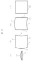
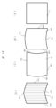
- FIG. 1 shows an example of the use form and configuration of a space-floating image display device according to one embodiment.
- FIG. 1 (A) shows the overall configuration of the space-floating image display device according to this embodiment.
- a show window (window glass) 105 which is a light-transmitting member (also described as a transparent member) such as glass, divides the space.
- a transparent member such as glass
- FIG. 1 (A) shows a case where the back side of the window glass 105 in the depth direction is the store space and the front side is the outside store space (e.g., the sidewalk).
- a means for reflecting a specific polarized wave such as an optical component
- the image display device 1 includes an image display unit 1a that displays the original image of the floating image 3, an image control unit 1b that converts the input image to match the resolution of the panel of the image display unit 1a, an image signal receiving unit 1c that receives an image signal, and a receiving antenna 1d.
- the image signal receiving unit 1c is compatible with wired input signals such as USB (Universal Serial Bus: registered trademark) input and HDMI (High-Definition Multimedia Interface: registered trademark) input, and wireless input signals such as Wi-Fi (Wireless Fidelity: registered trademark).
- the image display device 1 can function independently as an image receiving and display device, and can also display image information from an external PC, tablet, smartphone, etc. Furthermore, if a stick PC or the like is connected, the image display device 1 can be equipped with capabilities such as calculation processing and image analysis processing.
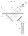
- FIG. 2A shows an example of the configuration of the main part of a space floating image display device according to an embodiment.
- the embodiment of FIG. 2A shows a configuration in which an image display device 1 and a retroreflective member (in other words, a retroreflective plate) 2 are arranged in a substantially V-shape (hereinafter, referred to as a V-shape).
- a V-shape a substantially V-shape
- an image display device 1 that generates image light of a specific polarization is provided in an oblique direction (a direction corresponding to an optical axis A1) relative to a transparent member 100 such as flat glass (arranged horizontally in this example).
- a retroreflective member 2 is provided in another oblique direction (a direction corresponding to an optical axis A2) relative to the transparent member 100 such as flat glass.
- the image display device 1 is composed of a light source device 13, a liquid crystal display panel 11 which is a liquid crystal display element, an absorbing polarizing plate 12, and the like.
- image light of a specific polarization emitted from the liquid crystal display panel 11 of the image display device 1 travels in the direction of optical axis A1, is reflected by a beam splitter 101 (polarization separation member) having a film that selectively reflects image light of a specific polarization provided on a transparent member 100, travels in the direction of optical axis A2, and is incident on the retroreflective member 2.
- the beam splitter 101 is formed in a sheet shape and adhered to the underside of the transparent member 100 such as flat glass.
- the beam splitter 101 may be formed by evaporating an optical thin film directly onto the flat glass.
- the image light incidence surface (in other words, the retroreflective surface) of the retroreflective member 2 is provided with a ⁇ /4 plate 21.
- the ⁇ /4 plate 21 is a polarization conversion element, a phase difference plate, and a quarter-wave plate.
- the image light on the optical axis A2 from the beam splitter 101 is passed through the ⁇ /4 plate 21 twice, once when it enters the retroreflective member 2 and once when it leaves the retroreflective member 2, and is polarized and converted from a specific polarization (one polarized wave) to the other polarized wave.
- the beam splitter 101 which selectively reflects the image light of a specific polarization, has the property of transmitting the image light of the other polarized wave after the polarization conversion. Therefore, the image light of the other polarized wave after the polarization conversion passes through the beam splitter 101.
- the image light that passes through the beam splitter 101 forms and displays the real image, the floating image 3, at a predetermined position outside the transparent member 100 in the direction of the optical axis A3 corresponding to the optical axis A2.
- the light that forms the floating image 3 is a collection of light rays that converge from the retroreflective member 2 to the optical image of the floating image 3, and these light rays continue to travel in a straight line even after passing through the optical image of the floating image 3. Therefore, in the configuration of FIG. 2A, when a user views the floating image 3 from direction A, which corresponds to the optical axis A3, the floating image 3 is seen as a bright image. However, when viewed by another person from direction B, for example, as shown by the arrow, the floating image 3 cannot be seen as an image at all. These characteristics are extremely suitable for use in systems that display images that require high security or highly confidential images that should be concealed from people directly facing the user.
- the polarization axis of the reflected image light may become misaligned.
- a portion of the image light with a misaligned polarization axis is reflected by the beam splitter 101 described above and returns to the image display device 1.
- This returned light may be re-reflected on the image display surface of the liquid crystal display panel 11 constituting the image display device 1, generating a ghost image and possibly degrading the image quality of the floating image 3. Therefore, in this embodiment, an absorbing polarizing plate 12 is provided on the image display surface of the image display device 1.
- the image light emitted from the image display device 1 is transmitted through the absorbing polarizing plate 12, and the reflected light returning from the beam splitter 101 is absorbed by the absorbing polarizing plate 12. This makes it possible to suppress the re-reflection and prevent degradation of image quality due to ghost images of the floating image 3.
- the above-mentioned beam splitter (polarization separation member) 101 is formed, for example, from a reflective polarizing plate or a metal multilayer film that reflects a specific polarized wave. More specifically, the beam splitter 101 can be formed by evaporating an optical thin film onto flat glass (for example, quartz glass).
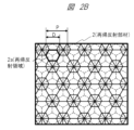
- Retroreflective member 2B shows an example of the surface shape of a retroreflector as a representative retroreflective member 2.
- a light ray incident on the interior of regularly arranged triangular pyramid prisms is reflected by three walls and a bottom surface of the triangular pyramid prism and is emitted as retroreflected light in a direction corresponding to the incident light, and a real image floating in space is displayed based on the image displayed on the display device 1.
- the resolution of this floating image 3 depends heavily on the outer diameter D and pitch P of the retroreflective area 2a (area surrounded by a hexagon) of the retroreflective member 2 shown in FIG. 2B, in addition to the resolution of the liquid crystal display panel 11.
- the resolution of the liquid crystal display panel 11 depends heavily on the outer diameter D and pitch P of the retroreflective area 2a (area surrounded by a hexagon) of the retroreflective member 2 shown in FIG. 2B, in addition to the resolution of the liquid crystal display panel 11.
- the effective resolution of the floating image 3 is reduced to about 1/3.
- the diameter D and pitch P of the retroreflective area 2a closer to one pixel of the liquid crystal display panel 11.
- the pitch ratio of each it is advisable to design the pitch ratio of each to be a different integer multiple of one pixel. Also, it is advisable to arrange the shape so that none of the sides of the retroreflective region 2a overlaps with any of the sides of one pixel of the liquid crystal display panel 11.
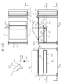
- FIG. 3 shows an example of the configuration of the main parts of a space floating image display device according to an embodiment, which is different from the embodiment of Fig. 2A.
- the embodiment of Fig. 3 shows a configuration in which an image display device 1 and a retroreflective member 2 (retroreflective plate) are arranged opposite each other, and a beam splitter 101 is arranged in the space connecting them at an angle of about 45 degrees to the image display device 1 and the retroreflective member 2, roughly in a Z shape (or inverted Z shape) (hereinafter referred to as Z shape).
- Z shape or inverted Z shape
- the Z-shaped configuration shown in FIG. 3 includes a transparent member 100 such as a glass plate and an absorbing polarizer 112 for the purpose of reducing the effect of external light incident from direction C on the retroreflective member 2 and image display device 1.
- the image display device 1 and the retroreflective member 2 are disposed at an angle of about 90 degrees to the transparent member 100 and the absorbing polarizer 112, and at an angle of about 45 degrees to the beam splitter 101.
- the beam splitter 101 is disposed horizontally, and the position of the image displayed on the image display device 1, more specifically the liquid crystal display panel 11, and the position where the floating image 3 is formed are plane-symmetrical to the beam splitter 101.
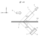
- FIG. 4A Another example of the optical system of the space floating image display device will be described with reference to FIG. 4A.
- the optical system of FIG. 4A is an optical system using a retroreflector 5 different from the retroreflector 2 used in FIG. 2A, FIG. 2B, and FIG. 3.
- FIG. 4F another example of the optical system will be described in more detail with reference to FIG. 4A to FIG. 4F.
- the components with the same reference numerals as those in FIG. 2A, FIG. 2B, and FIG. 3 have the same functions and configurations as those in FIG. 2A, FIG. 2B, and FIG. 3. Such components will not be described repeatedly in order to simplify the explanation.
- FIG. 4A is a diagram showing an example of the main components and retroreflective components of a spatial floating image display device according to one embodiment of the present invention.
- a display device 10 that emits image light is provided in an oblique direction of a transparent member 100 such as glass.
- the display device 10 includes a liquid crystal display panel 11 and a light source device 13 that generates light.
- the chief ray 9020 which represents the light beam emitted from the display device 10, travels toward the retroreflector 5 and is incident on the retroreflector 5 at an incident angle ⁇ .
- the incident angle ⁇ may be, for example, 45°.
- the incident angle ⁇ is not limited to 45°, and may be, for example, 45° ⁇ 15°.
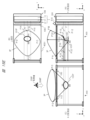
- the retroreflector 5 is an optical element that has the optical property of retroreflecting light rays in at least some directions.
- the retroreflector 5 may also be referred to as an imaging optical element or imaging optical plate.
- the retroreflector 5 causes the main ray 9020 to travel in the z direction while being retroreflected in the x and y directions.
- the reflected ray 9021 travels along an optical path that is mirror-symmetrical to the main ray 9020 with the retroreflector 5 as the reference, in a direction away from the retroreflector 5, passes through the transparent member 100, and forms the floating-in-space image 3 as a real image on the imaging plane.
- the light beam that forms the floating image 3 is a collection of light rays that converge from the retroreflector 5 to the optical image of the floating image 3, and these light rays continue to travel in a straight line even after passing through the optical image of the floating image 3. Therefore, the floating image 3 is an image with high directionality, unlike a diffuse image formed on a screen by a general projector or the like. Therefore, in the configuration of FIG. 4A, when a user views the floating image 3 from the direction of arrow A, the floating image 3 is seen as a bright image. However, when another person views the floating image 3 from the direction of arrow B, the floating image 3 cannot be seen as an image at all. This characteristic is suitable for use in a system that displays images that require high security or highly confidential images that should be kept secret from people directly facing the user.
- the retroreflector 5 is configured by arranging multiple corner reflectors 9040 in an array on the surface of a transparent member. This may be called a corner reflector array or a multi-surface reflector array.
- the specific configuration of the corner reflector 9040 will be described in detail with reference to Figures 4D, 4E, and 4F.
- the light rays 9111, 9112, 9113, and 9114 emitted from the light source 9110 are reflected twice by the two mirror surfaces 9041 and 9042 of the corner reflector 9040, becoming reflected light rays 9121, 9122, 9123, and 9124.
- this double reflection is a retroreflection that turns back in the same direction as the incident direction (travels in a direction rotated 180 degrees), and in the z direction, it is a regular reflection in which the angle of incidence and the angle of reflection match due to total reflection.
- the light rays 9111 to 9114 generate reflected light rays 9121 to 9124 on a straight line symmetrical in the z direction with respect to the corner reflector 9040, forming an aerial real image 9120.
- the light rays 9111 to 9114 emitted from the light source 9110 are four light rays that represent the diffused light from the light source 9110, and although the light rays that enter the retroreflector 5 are not limited to these depending on the diffusion characteristics of the light source 9110, all of the incident light rays cause similar reflections and form an aerial real image 9120.
- the position of the light source 9110 and the position of the aerial real image 9120 in the x direction are shifted, but in reality the position of the light source 9110 and the position of the aerial real image 9120 in the x direction are the same, and are overlapping when viewed from the z direction.
- the corner reflector 9040 is a rectangular parallelepiped with only two specific faces being mirror surfaces 9041 and 9042, and the other four faces being made of transparent material.
- the retroreflector 5 has a configuration in which the corner reflectors 9040 are arrayed so that the corresponding mirror surfaces face in the same direction.
- mirror surface 9041 When viewed from the top (+z direction), light ray 9111 emitted from light source 9110 is incident on mirror surface 9041 (or mirror surface 9042) at a specific angle of incidence, is totally reflected at reflection point 9130, and is then totally reflected again at reflection point 9132 on mirror surface 9042 (or mirror surface 9041).
- the angle of incidence of light ray 9111 with respect to mirror surface 9041 (or mirror surface 9042) is ⁇
- the angle of incidence of the first reflected light ray 9131 reflected by mirror surface 9041 (or mirror surface 9042) with respect to mirror surface 9042 (or mirror surface 9041) can be expressed as 90°- ⁇ . Therefore, with respect to light ray 9111, the second reflected light ray 9121 rotates by 2 ⁇ after the first reflection and by 2 ⁇ (90°- ⁇ ) after the second reflection, resulting in a total inversion optical path of 180°.
- total reflection in the z direction occurs only once. Therefore, if the angle of incidence with respect to mirror surface 9041 or mirror surface 9042 is ⁇ , the reflected light ray 9121 rotates by 2 ⁇ after one reflection with respect to light ray 9111.
- the light rays incident on the corner reflector 9040 undergo retroreflection with inverted optical paths in the x and y directions, and undergo regular reflection due to total reflection in the z direction.
- the retroreflector 5 Similar reflections occur in each optical path, so that an image is formed at a point symmetrical with respect to the z-axis direction due to the inverted optical paths that are convergent in the x and y directions.
- the retroreflector 2 has retroreflection properties in three axial directions.
- the reflected light beam with convergence travels towards the side of the retroreflector 2 where the light source of the incident light is located.
- This reflected light beam with convergence forms an image in the air to form a floating image 3.
- the traveling direction of the chief ray of the reflected light beam with convergence reflected from the retroreflector 2 is the opposite direction to the traveling direction of the chief ray of the incident light beam with diffusivity that is incident on the retroreflector 2.
- the retroreflector 5 has retroreflection properties in two axial directions, and is specular in the other axial direction.
- the retroreflector 5 when a diffusive incident light beam is incident on the retroreflector 5, the convergent reflected light beam reflected by the corner reflector array travels toward the side of the retroreflector 5 opposite to the side where the light source of the incident light is located. This convergent reflected light beam forms an image in the air, forming the floating image 3.
- the direction of travel of the chief ray of the convergent reflected light beam reflected by the corner reflector array of the retroreflector 5 is not the opposite direction to the direction of travel of the chief ray of the diffusive incident light beam incident on the retroreflector 5.
- the normal component of the plate-shaped surface of the retroreflector 5 in the direction of travel of the chief ray of the diffusive incident light beam incident on the retroreflector 5 and the normal component of the plate-shaped surface of the retroreflector 5 in the direction of travel of the chief ray after being reflected by the retroreflector 5 to become a convergent reflected light beam continue to travel in a straight line before and after reflection by the corner reflector array.
- the diffusive incident light beam is converted into a convergent reflected light beam by reflection on the retroreflector 5, but in the normal direction to the plate-shaped surface of the retroreflector 5, this light beam travels as if passing through the retroreflector 5.
- the diffusive incident light beam that enters the retroreflector 5 and the convergent reflected light beam that exits from the retroreflector 5 are geometrically symmetrical with respect to the plate-shaped surface of the retroreflector 5.
- the surface shape of the retroreflector of this embodiment is not limited to the above example. It may have various surface shapes that realize retroreflection. Specifically, the surface of the retroreflector of this embodiment may be provided with retroreflection elements in which triangular pyramid prisms, hexagonal pyramid prisms, other polygonal prisms, or combinations of these are periodically arranged. Alternatively, the surface of the retroreflector of this embodiment may be provided with retroreflection elements in which these prisms are periodically arranged to form cube corners. These can also be expressed as corner reflector arrays and multifaceted reflector arrays. Alternatively, the surface of the retroreflector of this embodiment may be provided with capsule lens-type retroreflection elements in which glass beads are periodically arranged.
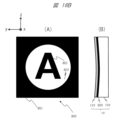
- the inventors have experimentally determined the relationship between the amount of blur l (small L) and the pixel size L (large L) of the image of the floating image 3 that is acceptable for improving visibility by creating an image display device 1 that combines a liquid crystal display panel 11 with a pixel pitch of 40 ⁇ m and a light source device 13 with a narrow divergence angle (divergence angle of 15°) of this embodiment.
- Figure 5 shows the experimental results. It was found that the amount of blur l that deteriorates visibility is preferably 40% or less of the pixel size, and is barely noticeable if it is 15% or less.
- the surface roughness of the reflective surface at which this amount of blur l is acceptable is an average roughness of 160 nm or less within a measurement distance of 40 ⁇ m, and it was found that to achieve a less noticeable amount of blur l, the surface roughness of the reflective surface is preferably 120 nm or less. For this reason, it is desirable to reduce the surface roughness of the retroreflective member 2 described above, and to keep the surface roughness of the reflective film and its protective film that form the reflective surface below the above-mentioned value.
- a roll press method for molding involves aligning the retroreflective members 2a and shaping them on a film.
- the inverse shape of the shape to be shaped is formed on the surface of a roll, an ultraviolet-curable resin is applied onto a base material for fixing, and the required shape is formed by passing it between the rolls, and then the desired shape is obtained by irradiating ultraviolet light to harden it.
- the image display device 1 of this embodiment uses a liquid crystal display panel 11 and a light source device 13 (see FIG. 6 for details) as a light source that generates light of a specific polarization, which reduces the possibility of image light being incident obliquely on the retroreflective member 2 described above. As a result, the occurrence of ghost images is suppressed, and even if a ghost image does occur, the brightness of the ghost image is low, resulting in a structurally excellent system.
- the image display device 1 which is configured with a liquid crystal display panel 11, an absorptive polarizer 12, and a light source device 13, is disposed at a predetermined angle (for example, an angle of about 45 degrees with respect to the beam splitter 101 in the horizontal plane).
- the image light from the image display device 1 passes through the beam splitter 101 in the direction of optical axis B1 (diagonal direction with respect to the beam splitter 101), and proceeds toward the retroreflective member 2 in the direction of optical axis B2 (corresponding to direction D) that corresponds to the optical axis B1.
- the image light from the image display device 1 is image light having the characteristics of a specific polarization, for example, P-polarized (parallel polarization).
- the beam splitter 101 is a polarization separation member such as a reflective polarizing plate, and has the property of transmitting P-polarized image light from the image display device 1 but reflecting S-polarized (vertical polarization) image light.
- This beam splitter 101 is formed from a reflective polarizing plate or a metal multilayer film that reflects specific polarization.
- This beam splitter 101 can generally be formed by evaporating an optical thin film onto a flat glass substrate. Therefore, the refractive index of the beam splitter 101 has substantially the same value as the refractive index n (n ⁇ 1.5) of flat glass.
- a ⁇ /4 plate 21 is provided on the light incidence surface (retroreflective surface) of the retroreflective member 2.
- the P-polarized image light transmitted through the beam splitter 101 from the image display device 1 is polarized and converted from P-polarized to S-polarized light by passing through the ⁇ /4 plate 21 twice in total when it enters and leaves the retroreflective member 2.
- the S-polarized image light after polarization conversion from the retroreflective member 2 is reflected by the beam splitter 101 and travels toward the transparent member 100, etc.
- the S-polarized image light that travels in a direction corresponding to the optical axis B3 after reflection (diagonal direction with respect to the beam splitter 101) passes through the transparent member 100 made of a glass plate or the like and the absorbing polarizing plate 112, and generates and displays the real image, which is a floating image 3, at a predetermined position outside the transparent member 100, etc.
- the retroreflective member 2 in order to reduce degradation of image quality caused by sunlight or illumination light entering an optical system composed of optical components such as the image display device 1, the retroreflective member 2, and the beam splitter 101, it is advisable to provide an absorptive polarizing plate 112 on the outer surface of the transparent member 100. Since the polarization axis may become uneven due to the retroreflective member 2 reflecting light, some of the image light may be reflected by the beam splitter 101 and returned to the image display device 1. This returned light is reflected again by the image display surface of the liquid crystal display panel 11 constituting the image display device 1, generating a ghost image and significantly degrading the image quality of the floating image 3 in space.
- an absorptive polarizer 12 is provided on the image display surface of the image display device 1.
- an anti-reflection film (not shown) may be provided on the image output side of the absorptive polarizer 12 provided on the surface of the image display device 1. In this way, the light that causes the ghost image to be generated is absorbed by the absorptive polarizer 12, thereby preventing degradation of image quality due to the ghost image of the floating image 3 in space.
- the retroreflective member 2 is tilted downward with respect to the direction of incidence of the external light to prevent the incidence of the external light.
- the main incident direction of the external light is set to a direction (diagonal direction like the optical axis B3) corresponding to the direction C indicated by the arrow (the direction in which the user views the floating image 3 from the front).
- the retroreflective member 2 is arranged so that the optical axis B2 is, for example, at an angle of about 90 degrees with respect to the direction C (optical axis B3).
- the image display device 1 is also arranged in a different direction from the incident direction of the external light (direction C). Specifically, the main surface (image light exit surface) of the image display device 1 is arranged in the same direction (in other words, parallel) as the main surface of the retroreflective member 2, and the optical axis B1 of the image display device 1 is arranged at an angle of approximately 90 degrees to the optical axis B3 corresponding to the incident direction of the external light (direction C). Furthermore, when considering the range of the light flux when external light is incident on the main surface of the transparent member 100 functioning as an opening in direction C, the image display device 1 is arranged at a position slightly outside that range. This reduces the occurrence of ghost images caused by re-reflection at the image display device 1.
- FIG. 6 shows a configuration example of an image display device 1 applicable to the embodiments of Fig. 2A and Fig. 3.
- This image display device 1 is configured to include a light source device 13, a liquid crystal display panel 11, a light direction conversion panel 54, etc.
- the image output surface side of the liquid crystal display panel 11 may be provided with the above-mentioned absorptive polarizing plate 12.
- the light source device 13 is configured to include a plurality of LED elements 201 (LEDs: Light Emitting Diodes) which are semiconductor light sources (solid light sources) constituting the light source, a light guide 203, etc.
- Fig. 6 shows a developed perspective view of the state in which the liquid crystal display panel 11 and the light direction conversion panel 54 are arranged on the light output side of the light source device 13.
- the light source device 13 is formed, for example, from a plastic case (not shown) and is configured to house the LED elements 201 and the light guide 203 inside.
- a light receiving end surface 203a is provided on the light incident side of the light guide 203 to convert the divergent light from each LED element 201 into a substantially parallel beam.
- the light receiving end surface 203a has a shape in which the cross-sectional area gradually increases toward the opposite side to the light receiving portion, and is provided with a lens shape that has the effect of gradually decreasing the divergence angle by multiple total reflections as the light propagates inside.
- the liquid crystal display panel 11 is attached to the upper surface of the light guide 203, and is disposed approximately parallel to the light guide 203.
- the upper surface of the light guide 203 serves as an emission surface that emits light reflected by the light guide 203.
- a plurality of LED elements 201 are attached to one side (the lower side in FIG. 6) of the case of the light source device 13. The light from the plurality of LED elements 201 is converted into approximately collimated light (approximately parallel light) by the shape of the light receiving end surface 203a of the light guide 203. For this reason, the light receiving portion of the light receiving end surface 203a and the LED elements 201 are attached while maintaining a predetermined positional relationship.
- the light source device 13 is configured by attaching a light source unit in which a plurality of LED elements 201 serving as light sources are arranged to the light receiving end surface 203a, which is a light receiving section provided on the light incident side of the light guide 203.
- the divergent light beam from the LED elements 201 is made into approximately collimated light by the lens shape of the light receiving end surface 203a of the light guide 203. This approximately collimated light is guided inside the light guide 203 in the direction A indicated by the arrow.
- the direction A is approximately parallel to the liquid crystal display panel 11 (from bottom to top in the drawing).
- the light guided in the direction A has its light beam direction converted by the light beam direction conversion section 204 provided in the light guide 203, and is emitted in the direction B indicated by the arrow toward the liquid crystal display panel 11, which is approximately parallel to the light guide 203.
- the direction B is approximately perpendicular to the display surface of the liquid crystal display panel 11.
- the light guide 203 has a configuration in which the distribution (in other words, density) of the light beam direction conversion section 204 is optimized depending on the shape inside or on the surface of the light guide 203. This makes it possible to control the uniformity of the light, which is the light beam emitted from the light source device 13 shown in direction B and incident on the liquid crystal display panel 11.
- the directivity of the light in direction B from the light source device 13 can be controlled to improve the utilization efficiency of the light flux emitted from the light source device 13 shown in direction B and significantly reduce power consumption.
- a light source having a narrow divergence angle can be configured as the light source device 13.
- the image light from the image display device 1 reaches the observer efficiently with high directivity (in other words, linearity) like laser light, and a high-quality floating image can be displayed at high resolution.
- the power consumption by the image display device 1 including the LED elements 201 of the light source device 13 can be significantly reduced.
- the liquid crystal display panel 11 is attached to a frame (not shown) of the liquid crystal display panel 11, which is attached to the top surface of a case (not shown) of the light source device 13, and is configured by mounting the liquid crystal display panel 11 attached to the frame and a flexible printed circuit board (FPC: Flexible Printed Circuits) (not shown) electrically connected to the liquid crystal display panel 11.
- the liquid crystal display panel 11, which is a liquid crystal display element, generates a display image by modulating the intensity of transmitted light together with the LED elements 201 based on a control signal from a control circuit (not shown) that constitutes the electronic device.
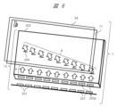
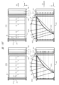
- FIG. 7 a table-top type floating image display device according to one embodiment will be described with reference to FIG. 7 and subsequent figures.
- the floating image display device according to each embodiment shown in FIG. 7 to FIG. 9 has a basic configuration similar to the V-shaped configuration shown in FIG. 2A.
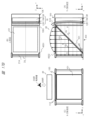
- FIG. 7 shows an example of the configuration of the main parts of a space floating image display device 400 suitable for installation on a desk, according to one embodiment (hereinafter referred to as a first embodiment).
- FIG. 7 shows a cross-sectional view of the space-floating image display device 400 as seen from the side.
- the front of the device here corresponds to the direction in which the space-floating image 3 (3A, 3B) formed by the space-floating image display device 400 can be viewed from the front by the user (230A, 230B).
- Directions AA and AB are the directions in which the user views the floating image 3 (3A, 3B) from the front, and correspond to the negative direction in the Y direction.
- a coordinate system and directions such as (X, Y, Z) shown in the figure may be used.
- the Z direction is the vertical direction
- the X direction and the Y direction are two horizontal directions that intersect at right angles
- the X direction is the depth direction
- the front-to-back direction (the front-to-back horizontal direction within the screen of the floating image 3)
- the Y direction is the left-to-right direction (the left-to-right horizontal direction within the screen of the floating image 3).
- the basic configuration of the V-shaped structure in FIG. 7 is the same as that of the V-shaped structure in FIG. 2A in terms of the positional relationship of the components (image display device 1, beam splitter 101A and transparent member 100A, and retroreflective member 2, etc.).
- the image display device 1 includes a liquid crystal display panel 11 and a light source device 13.
- the beam splitter 101A and the transparent member 100A will be treated as one unit, and the transparent member will be abbreviated. Other similar components will also be abbreviated in the same way.
- the components of the floating-in-space image display device 400 are arranged with a predetermined positional relationship to each other. That is, the image display device 1, beam splitter 101A, retroreflective member 2, etc. in FIG. 7 are arranged with a predetermined positional relationship to form a V-shape, similar to the configuration in FIG. 2A.
- the formed floating-in-space image 3A can be viewed from the front by the user 230A in the direction AA.
- the first embodiment of the floating image display device 400 shown in FIG. 7 has a hinge mechanism 330 that serves as a rotation fulcrum at one end of the beam splitter 101A.
- the hinge mechanism 330 does not move up, down, left, or right, but is free to rotate. It is provided in the X direction at the left end of the beam splitter 101A, and the beam splitter 101A can rotate up and down around the hinge mechanism 330, which serves as a rotation fulcrum.
- the 7 has a display panel that displays an image, a polarizing separation member that reflects a portion of the image light emitted from the display panel, and a retroreflective member that retroreflects the reflected light from the polarizing separation member, and the reflected light reflected by the retroreflective member passes through the polarizing separation member to form a floating image, and the angle of the polarizing separation member with respect to the display panel and the retroreflective member is variable.
- the image display device 1 and the retroreflective member 2 are fixed in position, while the beam splitter 101A and the transparent member 100A can be positioned at different angles.
- the beam splitter 101A and the transparent member 100A can be rotated around the hinge mechanism 330 as a rotation fulcrum, changing the distance between the beam splitter 101A and the image display device 1, and the beam splitter 101A and the retroreflective member 2. Even if the angle at which the beam splitter 101A and the transparent member 100A are positioned is different, they are positioned in a positional relationship to form a V-shape, similar to the configuration in FIG. 2A.
- the beam splitter 101A and the transparent member 100A are rotated upward by an angle ⁇ with respect to the horizontal position (XY plane) using the hinge mechanism 330 as a rotation fulcrum, and placed at the position of the beam splitter 101B and the transparent member 100B.
- the image light from the image display device 1 passes through the optical axis AB1, which is longer than the optical axis A1, is reflected by the beam splitter 101B, passes through the ⁇ /4 plate 21 along the optical axis AB2, and enters the retroreflective member 2.
- the image light that is retroreflected by the retroreflective member 2 and emitted passes through the ⁇ /4 plate 21 again, where it is converted to the other polarization, and passes through the beam splitter 101B.
- the image light that passes through the beam splitter 101B forms and displays a real image, a floating-in-space image 3B, at a predetermined position outside the transparent member 100B in the direction of the optical axis AB3 that corresponds to the optical axis AB2.
- the formed floating-in-space image 3B can be viewed as a bright image by the user 230B in a frontal position from the direction AB indicated by the arrow that corresponds to the optical axis AB3.
- beam splitter 101B is positioned above beam splitter 101A by angle ⁇ , the length of optical axis AB1 from image display device 1 to beam splitter 101B is longer than optical axis A1 from image display device 1 to beam splitter 101A, and floating image 3B is formed at a higher position than floating image 3A. For this reason, when the height of the viewpoint position differs due to differences in height between users, it is possible to form floating image 3 at an easily visible position by changing the tilt angle of beam splitter 101.
- beam splitter 101A in a horizontal position forms a floating image 3A that is optimal for user 230A
- beam splitter 101B with an upward angle of ⁇ with respect to the horizontal position (XY plane) forms a floating image 3B that is optimal for user 230B, who is taller than user 230A.
- FIG. 8 shows a configuration example of a space floating image display device 400 suitable for installation on a desk, according to one embodiment (hereinafter referred to as a second embodiment).
- Figure 8 shows a cross-sectional view of the floating-in-space image display device 400 as seen from the side.
- the floating-in-space image display device 400 of the first embodiment in FIG. 7 is placed in a housing 4001, and the housing 4001 has an opening (opening hole) 4002 in the horizontal direction (parallel to the XY plane).
- the hinge mechanism 330 is provided at one end of the opening 4002, and rotatably holds the beam splitter 101A at one side of the beam splitter 101A opposite the user 230, and serves as a rotation fulcrum for the beam splitter 101A.
- the floating-in-space image display device 400 also includes a control unit 500 having control functions, an imaging unit 510, and a piston mechanism 310 that moves the piston up and down or expands and contracts.
- FIG. 8 the positional relationship of the components (image display device 1, beam splitter 101A and transparent member 100A, retroreflective member 2, etc.) is the same as that of the V-shaped configuration in FIG. 7. Note that, hereinafter, beam splitter 101A and transparent member 100A will be treated as one unit, and the transparent member will be abbreviated. Other similar components will also be abbreviated in the same way.
- the components of the floating-in-space image display device 400 are arranged with a predetermined positional relationship to each other. That is, the image display device 1, beam splitter 101A, retroreflective member 2, etc. in FIG. 8 are arranged with a predetermined positional relationship to form a V-shape, similar to the configuration in FIG. 7.
- the formed floating-in-space image 3A can be viewed from the front by the user 230A from the direction AA.
- this structure allows beam splitter 101A and transparent member 100A to be positioned at different angles while image display device 1 and retroreflective member 2 are fixed in position.
- this structure allows beam splitter 101A and transparent member 100A to be rotated around hinge mechanism 330 as a rotation fulcrum, changing the separation distance between beam splitter 101A and image display device 1, and the separation distance between beam splitter 101A and retroreflective member 2.
- a display panel that displays an image
- a polarization separation member that reflects a portion of the image light emitted from the display panel
- a retroreflective member that retroreflects the light reflected from the polarization separation member, and the light reflected by the retroreflective member passes through the polarization separation member to form a floating image, and the angle of the polarization separation member relative to the display panel and the retroreflective member is variable.
- Piston mechanism 310 is disposed on the side of beam splitter 101A and transparent member 100A that faces hinge mechanism 330.
- the piston of piston mechanism 310 In the initial state, the piston of piston mechanism 310 is in contact with one side of beam splitter 101A and transparent member 100A with the length of piston 310A, holding beam splitter 101A and transparent member 100A horizontally (parallel to the XY plane).
- piston 310A of piston mechanism 310 extends and is in the state of piston 310B
- beam splitter 101A and transparent member 100A rotate upward by angle ⁇ with respect to the horizontal position (XY plane) with hinge mechanism 330 as the rotation fulcrum, and move to the position of beam splitter 101B and transparent member 100B. That is, the piston mechanism 310 rotates the beam splitter 101A around the hinge mechanism 330 of the rotation axis, allowing the angle relative to the image display device 1 and the retroreflective member 2 to be changed.
- the image light from the image display device 1 passes through the optical axis AB1, which is longer than the optical axis A1, is reflected by the beam splitter 101B, passes through the ⁇ /4 plate 21 along the optical axis AB2, and enters the retroreflective member 2.
- the image light that is retroreflectively reflected by the retroreflective member 2 passes through the ⁇ /4 plate 21 again, is converted to the other polarization, and transmits the beam splitter 101B.
- the image light that transmits the beam splitter 101B forms and displays the real image, the floating image 3B, at a specified position outside the transparent member 100B, in the direction of the optical axis AB3 corresponding to the optical axis AB2.
- the formed floating image 3B can be viewed as a bright image by the user 230B in the front position from the direction AB indicated by the arrow corresponding to the optical axis AB3.
- the arrangement of the piston mechanism 310 is not limited to this embodiment, and similar effects can be obtained by arranging it on other sides of the beam splitter 101A and the transparent member 100A, or in multiple positions. Also, the method of rotating or driving the beam splitter 101A in the vertical direction with the hinge mechanism 330 as the rotation fulcrum is not limited to the piston mechanism 310.
- the imaging unit 510 captures images of the height, face, and facial components such as the eyes and mouth of the user 230, and information such as the height and face of the user 230 is input to the control unit 500.
- the imaging unit 510 detects, for example, the position of the eyes of the user 230 from the input information of the user 230, and obtains information on the height of the eyes of the user 230.
- control unit etc. 500 can drive the piston mechanism 310 to change the angle of the beam splitter 101A to a position optimal for the user 230's viewing.
- image capture unit 510 and control unit 500 control piston mechanism 310 so that beam splitter 101A holds the horizontal position.
- image capture unit 510 and control unit 500 extend piston 310A of piston mechanism 310 to piston 310B, and change the position of beam splitter 101A to that of beam splitter 101B tilted by angle ⁇ , allowing user 230B to view a bright image from a frontal position.
- FIG. 9 shows a configuration example of a space floating image display device suitable for installation on a desk, according to one embodiment (hereinafter referred to as a third embodiment).
- FIG. 9 shows a cross-sectional view of the floating-in-space image display device as seen from the side.
- the floating-in-space image display device 400 is disposed inside a housing 4001.
- FIG. 9 the positional relationships of the components (image display device 1, beam splitter 101A and transparent member 100A, retroreflective member 2, etc.) are the same as those of the V-shaped configuration in FIG. 2A.
- beam splitter 101A and transparent member 100A will be treated as a single unit, and the transparent member will be abbreviated.
- Other similar components will also be abbreviated in the same way.
- the components of the floating-in-space image display device are arranged with a predetermined positional relationship to each other. That is, the image display device 1, beam splitter 101A, retroreflective member 2, etc. in FIG. 9 are arranged with a predetermined positional relationship to form a V-shape, similar to the configuration in FIG. 2A.
- the formed floating-in-space image 3A can be viewed from the front by user 230A in direction AA.
- hinge mechanism 331 is provided near the center of opening 4002, rotatably holds both ends of beam splitter 101A at or near the center line of beam splitter 101A that is parallel to one side of beam splitter 101A facing user 230, and serves as a rotation fulcrum for beam splitter 101A.
- Hinge mechanism 331 does not move up, down, left, or right, but is free to rotate, and beam splitter 101A is structured to rotate up and down around hinge mechanism 331 as a rotation fulcrum.
- a display panel that displays an image
- a polarization separation member that reflects a portion of the image light emitted from the display panel
- a retroreflective member that retroreflects the light reflected from the polarization separation member, and the light reflected by the retroreflective member passes through the polarization separation member to form a floating image, and the angle of the polarization separation member relative to the display panel and the retroreflective member is variable.
- the image display device 1 and the retroreflective member 2 are fixedly arranged, while the beam splitter 101A and the transparent member 100A can be arranged at different angles.
- the beam splitter 101A and the transparent member 100A can be rotated around the hinge mechanism 331 as a rotation fulcrum, changing the distance between the beam splitter 101A and the image display device 1, and the beam splitter 101A and the retroreflective member 2. Even if the arrangement angle of the beam splitter 101A and the transparent member 100A is different, they are arranged with a positional relationship so as to form a V shape, similar to the configuration in FIG. 2A.
- the piston mechanism 310 is disposed on the side of the beam splitter 101A and the transparent member 100A facing the user 230.
- the piston of the piston mechanism 310 In the initial state, the piston of the piston mechanism 310 is in contact with one side of the beam splitter 101A and the transparent member 100A at the length of the piston 310A, and holds the beam splitter 101A and the transparent member 100A horizontally (parallel to the XY plane).
- the piston 310A of the piston mechanism 310 extends and is in the state of piston 310C
- the beam splitter 101A and the transparent member 100A rotate upward by an angle ⁇ with respect to the horizontal position (XY plane) around the hinge mechanism 331 as the rotation fulcrum, and move to the position of the beam splitter 101C and the transparent member 100C.
- the piston mechanism 310 rotates the beam splitter 101A around the hinge mechanism 331 of the rotation axis as the rotation fulcrum, and the angle with respect to the image display device 1 and the retroreflective member 2 can
- the image light from the center position of the image display device 1 is reflected or passes along the optical axes A1, A2, and A3 on the rotation fulcrum axis (X-axis direction) of the hinge mechanism 331 of the beam splitter 101A.
- the beam splitter 101A and the transparent member 100A rotate by an angle and the image light from the center position of the image display device 1 reaches the position of the beam splitter 101C and the transparent member 100C, the path and length of the optical path is almost unchanged, so the image light is reflected by the beam splitters 101A and 101C, passes through the ⁇ /4 plate 21 along the optical axis A2, and enters the retroreflective member 2.
- the image light that is retroreflected by the retroreflective member 2 passes through the ⁇ /4 plate 21 again and is converted to the other polarized wave, and then passes through the beam splitters 101A and 101C.
- the image light that passes through the beam splitters 101A and 101C generates a real image, a floating image, at a predetermined position outside the transparent members 100A and 100C in the direction of the optical axis A3 that corresponds to the optical axis A2, and the floating images are generated at approximately the same position, so that the floating images 3A and 3C almost overlap.
- the image light of the optical axis A11 at the lower end of the image display device 1 is reflected by the beam splitter 101C, passes through the ⁇ /4 plate 21 along the optical axis C12, and enters the retroreflective member 2.
- the image light that is retroreflected by the retroreflective member 2 passes through the ⁇ /4 plate 21 again, is converted to the other polarized wave, and transmits through the beam splitter 101C.
- the image light that has transmitted through the beam splitter 101C generates a real image, a floating image 3C, at a predetermined position outside the transparent member 100C in the direction of the optical axis C13 corresponding to the optical axis C12.
- the distance between the bottom end of the image display device 1 and the beam splitter 101C becomes shorter than the distance between the image display device 1 and the beam splitter 101A due to the rotation of the angle ⁇ , in other words the optical path distance becomes shorter, so that the position of the top end (left end in FIG. 9) of the generated floating-in-space image 3C becomes lower than the position of the top end of the floating-in-space image 3A.
- the image light of the optical axis A21 of the top end (right end in FIG. 9) of the image display device 1 is reflected by the beam splitter 101A, it passes through the ⁇ /4 plate 21 along the optical axis A22 and enters the retroreflective member 2.
- the image light that is retroreflected by the retroreflective member 2 and emitted passes through the ⁇ /4 plate 21 again, is converted into the other polarized wave, and transmits through the beam splitter 101A.
- the image light transmitted through the beam splitter 101A generates a real image, a floating image 3A, at a predetermined position outside the transparent member 100A in the direction of optical axis A23, which corresponds to optical axis A22.
- the image light of the optical axis A21 at the upper end of the image display device 1 is reflected by the beam splitter 101C, passes through the ⁇ /4 plate 21 along the optical axis C22, and enters the retroreflective member 2.
- the image light that is retroreflected by the retroreflective member 2 passes through the ⁇ /4 plate 21 again, is converted to the other polarized wave, and transmits through the beam splitter 101C.
- the image light that has transmitted through the beam splitter 101C generates a real image, a floating image 3C, at a predetermined position outside the transparent member 100C in the direction of the optical axis C23 corresponding to the optical axis C22.
- the distance between the top of the image display device 1 and the beam splitter 101C becomes longer than the distance between the image display device 1 and the beam splitter 101A due to the rotation of the angle ⁇ , in other words the optical path distance becomes longer, so that the bottom end (left end in FIG. 9) of the generated floating-in-space image 3C becomes higher than the top end of the floating-in-space image 3A.
- floating image 3C is tilted counterclockwise more than floating image 3A, or the tilt angle of floating image 3C occurs at a shallower angle closer to the horizontal plane than floating image 3A.
- Floating image 3C can be seen as a bright floating image in front of user 230C, who is taller or has a higher viewpoint than user 230A, in the direction AC indicated by the arrow.
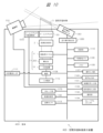
- FIG. 10 is a block diagram showing an example of the internal configuration of the space-floating image display device 400.
- the space-floating image display device 400 includes a retroreflective member 2, a liquid crystal display panel 11, a light guide 203, a light source device 13, a power source 1106, an external power source input interface 1111, an operation input unit 1107, a non-volatile memory 1108, a memory 1109, a control unit 1110, a video signal input unit 1131, an audio signal input unit 1133, a communication unit 1132, an aerial operation detection sensor 1351, an aerial operation detection unit 1350, an audio output unit 1140, a video control unit 1160, a storage unit 1170, an imaging unit 510, a beam splitter 101, a beam splitter angle adjustment unit 1010, and the like.
- the beam splitter angle adjustment unit 1010 includes the piston mechanism 310 shown in Figures 8 and 9, and adjusts the angle of the beam splitter 101 relative to the image display device 1 and the retroreflective member 2.
- a removable media interface 1134 may also be included.
- a position sensor 1113 may also be included.
- a transmissive self-luminous image display device may also be included.
- the components of the space floating image display device 400 are arranged in a housing 4001.
- the imaging unit 510 and the aerial operation detection sensor 1351 may be provided on the outside of the housing 4001.
- the retroreflective member 2 retroreflects the light modulated by the liquid crystal display panel 11.
- the light reflected from the retroreflective member 2 is output to the outside of the spatial floating image display device 400 to form the spatial floating image 3.
- the liquid crystal display panel 11 is a display unit that generates an image by modulating transmitted light based on an input video signal under the control of the video control unit 1160 described below.
- a transmissive liquid crystal panel is used.
- a reflective liquid crystal panel that modulates reflected light or a DMD (Digital Micromirror Device: registered trademark) panel may be used.
- the light source device 13 supplies light to the liquid crystal display panel 11 and is a solid-state light source such as an LED light source or a laser light source.
- the power supply 1106 converts AC current input from the outside via the external power supply input interface 1111 into DC current and supplies power to the light source device 13.
- the power supply 1106 also supplies the necessary DC current to each part within the space floating image display device 400.
- the secondary battery 1112 stores the power supplied from the power source 1106. Furthermore, when power is not supplied from the outside via the external power input interface 1111, the secondary battery 1112 supplies power to the light source device 13 and other components that require power. In other words, when the space floating image display device 400 is equipped with the secondary battery 1112, the user can use the space floating image display device 400 even when power is not supplied from the outside.
- the light guide 203 guides the light generated by the light source device 13 and irradiates it onto the liquid crystal display panel 11.
- the combination of the light guide 203 and the light source device 13 can also be called the backlight of the liquid crystal display panel 11.
- the light guide 203 may be configured mainly using glass.
- the light guide 203 may be configured mainly using plastic.
- the light guide 203 may be configured using a mirror. There are various possible methods for combining the light guide 203 with the light source device 13.
- the aerial operation detection sensor 1351 is a sensor that detects the operation of the floating-in-space image 3 by the finger of the user 230.
- the aerial operation detection sensor 1351 senses, for example, the entire display range of the floating-in-space image 3 and the range that overlaps with it.
- the aerial operation detection sensor 1351 may sense only a range that overlaps with at least a portion of the display range of the floating image 3. Specific examples of the aerial operation detection sensor 1351 include distance sensors that use invisible light such as infrared rays, invisible light lasers, ultrasonic waves, etc. The aerial operation detection sensor 1351 may also be configured to detect coordinates on a two-dimensional plane by combining multiple sensors. The aerial operation detection sensor 1351 may also be configured with a ToF (Time of Flight) type LiDAR (Light Detection and Ranging) or an image sensor.
- ToF Time of Flight
- LiDAR Light Detection and Ranging
- the mid-air operation detection sensor 1351 only needs to be capable of sensing to detect touch operations, etc., performed by the user with his/her finger on an object displayed as the floating-in-space image 3. Such sensing can be performed using existing technology.
- the aerial operation detection unit 1350 acquires a sensing signal from the aerial operation detection sensor 1351, and performs operations such as determining whether the finger of the user 230 has touched an object in the floating-in-space image 3 and calculating the position (contact position) where the finger of the user 230 has touched the object based on the sensing signal.
- the aerial operation detection unit 1350 is configured with a circuit such as an FPGA (Field Programmable Gate Array). Some of the functions of the aerial operation detection unit 1350 may be realized by software, for example, by a spatial operation detection program executed by the control unit 1110.
- the aerial operation detection sensor 1351 and the aerial operation detection unit 1350 may be configured to be built into the space-floating image display device 400, or may be provided separately from the space-floating image display device 400. When provided separately from the space-floating image display device 400, the aerial operation detection sensor 1351 and the aerial operation detection unit 1350 are configured to transmit information and signals to the space-floating image display device 400 via a wired or wireless communication connection path or image signal transmission path.
- the aerial operation detection sensor 1351 and the aerial operation detection unit 1350 may be provided separately. This makes it possible to build a system in which the main body is the floating-in-space image display device 400, which does not have an aerial operation detection function, and only the aerial operation detection function can be added as an option.
- the aerial operation detection sensor 1351 alone may be a separate component, and the aerial operation detection unit 1350 may be built into the space-floating image display device 400.
- the aerial operation detection sensor 1351 alone may be a separate component, and the aerial operation detection unit 1350 may be built into the space-floating image display device 400.
- the imaging unit 510 is a camera with an image sensor, and captures images of the face, eyes, arms, fingers, and/or the space near the floating image 3 of the user 230.
- the information on the face and eyes of the user 230 captured by the imaging unit 510 is used by the beam splitter angle adjustment unit 1010 to detect the position of the face and eyes of the user 230 and obtain height information. If the obtained height information differs from the pre-determined viewing height, the beam splitter angle adjustment unit 1010 can drive the piston mechanism 310 to change the angle of the beam splitter 101 to a position optimal for viewing by the user 230.
- a plurality of imaging units 510 may be provided. By using a plurality of imaging units 510, or by using an imaging unit with a depth sensor, the aerial operation detection unit 1350 can be assisted in the detection process of the touch operation of the user 230 on the floating-in-space image 3.
- the imaging unit 510 may be provided separately from the floating-in-space image display device 400. When the imaging unit 510 is provided separately from the floating-in-space image display device 400, it is sufficient to configure it so that an imaging signal can be transmitted to the floating-in-space image display device 400 via a wired or wireless communication connection path or the like.
- the aerial operation detection sensor 1351 may not be able to detect information such as how far an object that has not intruded into the intrusion detection plane (for example, a user's finger) is from the intrusion detection plane, or how close the object is to the intrusion detection plane.
- the distance between the object and the intrusion detection plane can be calculated by using information such as object depth calculation information based on the images captured by the multiple imaging units 510 and object depth information from a depth sensor.
- This information as well as various information such as the distance between the object and the intrusion detection plane, are used for various display controls for the floating-in-space image 3.
- the mid-air operation detection unit 1350 may detect touch operations on the floating-in-space image 3 by the user 230 based on the images captured by the imaging units 510.
- the imaging unit 510 may also capture an image of the face of the user 230 operating the floating image 3, and the control unit 1110 may perform an identification process for the user 230.
- the imaging unit 510 may also capture an image of the user 230 operating the floating image 3 and the surrounding area of the user 230 in order to determine whether or not another person is standing around or behind the user 230 operating the floating image 3 and peeking at the user's operation of the floating image 3.
- the operation input unit 1107 is, for example, an operation button, a signal receiving unit such as a remote controller, or an infrared light receiving unit, and inputs a signal for an operation different from the aerial operation (touch operation) by the user 230.
- the operation input unit 1107 may be used, for example, by an administrator to operate the floating-in-space image display device 400.
- Video signal input unit 1131 connects to an external video output device and inputs video data.
- Various digital video input interfaces are possible for video signal input unit 1131.
- it may be configured with a video input interface conforming to the HDMI (registered trademark) (High-Definition Multimedia Interface) standard, a video input interface conforming to the DVI (Digital Visual Interface) standard, or a video input interface conforming to the DisplayPort standard.
- an analog video input interface such as analog RGB or composite video may be provided.
- the audio signal input unit 1133 is connected to an external audio output device and inputs audio data.
- the audio signal input unit 1133 may be configured with an HDMI standard audio input interface, an optical digital terminal interface, or a coaxial digital terminal interface, etc.
- the video signal input unit 1131 and the audio signal input unit 1133 may be configured as an interface in which the terminals and cables are integrated.
- the audio output unit 1140 is capable of outputting audio based on the audio data input to the audio signal input unit 1133.
- the audio output unit 1140 may be configured as a speaker.
- the audio output unit 1140 may also output built-in operation sounds and error warning sounds.
- the audio output unit 1140 may be configured to output a digital signal to an external device, such as the Audio Return Channel function defined in the HDMI standard.
- Non-volatile memory 1108 stores various data used by the space floating image display device 400.
- Data stored in non-volatile memory 1108 includes, for example, data for various operations to be displayed on the space floating image 3, display icons, data for objects to be operated by the user, layout information, etc.
- Memory 1109 stores image data to be displayed as the space floating image 3, data for controlling the device, etc.
- the control unit 1110 controls the operation of each connected unit.
- the control unit 1110 may also work with a program stored in the memory 1109 to perform calculations based on information acquired from each unit in the space floating image display device 400.
- the communication unit 1132 communicates with external devices, external servers, etc., via a wired or wireless communication interface.
- the wired communication interface may be configured, for example, as an Ethernet standard LAN interface.
- the interface may be configured, for example, as a Wi-Fi communication interface, a Bluetooth communication interface, or a mobile communication interface such as 4G or 5G.
- Various types of data such as video data, image data, and audio data, are sent and received by communication via the communication unit 1132.
- the removable media interface 1134 is an interface for connecting a removable recording medium (removable media).
- the removable recording medium (removable media) may be composed of a semiconductor element memory such as a solid state drive (SSD), a magnetic recording medium recording device such as a hard disk drive (HDD), or an optical recording medium such as an optical disk.
- the removable media interface 1134 is capable of reading out various information such as various data including video data, image data, and audio data recorded on the removable recording medium.
- the video data, image data, and the like recorded on the removable recording medium are output as a floating image 3 via the liquid crystal display panel 11 and the retroreflective member 2.
- the storage unit 1170 is a storage device that records various information such as various data such as video data, image data, audio data, etc.
- the storage unit 1170 may be configured with a magnetic recording medium recording device such as a hard disk drive (HDD) or a semiconductor element memory such as a solid state drive (SSD).
- HDD hard disk drive
- SSD solid state drive
- various information such as various data such as video data, image data, audio data, etc. may be recorded in advance in the storage unit 1170 at the time of product shipment.
- the storage unit 1170 may also record various information such as various data such as video data, image data, audio data, etc. acquired from an external device or an external server via the communication unit 1132.
- the video data, image data, etc. recorded in the storage unit 1170 are output as the floating-in-space image 3 via the liquid crystal display panel 11 and the retroreflective member 2.
- the video data, image data, etc. of the display icons and objects for the user to operate, which are displayed as the floating-in-space image 3, are also recorded in the storage unit 1170.
- Layout information such as display icons and objects displayed as the floating-in-space image 3, and various metadata information related to the objects are also recorded in the storage unit 1170.
- the audio data recorded in the storage unit 1170 is output as audio from the audio output unit 1140, for example.
- the image control unit 1160 performs various controls related to the image signal input to the liquid crystal display panel 11.
- the image control unit 1160 may be called an image processing circuit, and may be configured with hardware such as an ASIC, an FPGA, or an image processor.
- the image control unit 1160 may also be called an image processing unit or an image processing unit.
- the image control unit 1160 performs image switching control, such as which image signal is input to the liquid crystal display panel 11 out of the image signal stored in the memory 1109 and the image signal (image data) input to the image signal input unit 1131.
- the image control unit 1160 may also generate a superimposed image signal by superimposing the image signal stored in the memory 1109 and the image signal input from the image signal input unit 1131, and input the superimposed image signal to the liquid crystal display panel 11 to form a composite image as the floating image 3.
- the video control unit 1160 may also control image processing of the video signal input from the video signal input unit 1131 and the video signal to be stored in the memory 1109. Examples of image processing include scaling processing for enlarging, reducing, transforming, etc. an image, brightness adjustment processing for changing the luminance, contrast adjustment processing for changing the contrast curve of an image, and Retinex processing for breaking down an image into light components and changing the weighting of each component.
- the video control unit 1160 may also perform special effect video processing, etc. for assisting the aerial operation (touch operation) of the user 230 on the video signal input to the liquid crystal display panel 11. The special effect video processing is performed, for example, based on the detection result of the touch operation of the user 230 by the aerial operation detection unit 1350 and the captured image of the user 230 by the imaging unit 510.
- the space-floating image display device 400 is equipped with various functions. However, the space-floating image display device 400 does not need to have all of these functions, and can have any configuration as long as it has the function of forming the space-floating image 3.
- FIG. 11 shows an example of the configuration of a floating-in-space image display device suitable for installation on a desk, according to one embodiment (hereinafter referred to as the fifth embodiment).
- FIG. 11 shows a cross-sectional view (A) of the floating-in-space image display device as viewed from the side, and a top view (B) of the device as viewed from the front.
- the front of the device here is the surface corresponding to the direction in which the user can view the floating-in-space image 3D formed by the floating-in-space image display device 400 from the front.
- Direction D is the direction in which the user views the floating-in-space image 3D from the front, and corresponds to the negative direction in the Z direction.
- a coordinate system or direction such as the illustrated (X, Y, Z) may be used.
- the Z direction is the vertical direction, the up-down direction, the X direction and the Y direction are two horizontal directions that are orthogonal to each other, the X direction is the depth direction, the front-back direction (the horizontal front-back direction on the screen of the floating-in-space image 3D), and the Y direction is the left-right direction (the horizontal left-right direction on the screen of the floating-in-space image 3D).
- the Z-shaped configuration in FIG. 11 has the same positional relationships of the components (image display device 1, beam splitter 101D, retroreflective member 2A, etc.) as the Z-shaped configuration in FIG. 3.
- the components of the floating-in-space image display device are mutually arranged with a predetermined positional relationship. That is, the image display device 1, beam splitter 101D, retroreflective member 2A, etc. of the image display device unit 300 in FIG. 11 are arranged with a predetermined positional relationship so as to form a Z shape, similar to the configuration in FIG. 3.
- the fifth embodiment of the floating image display device shown in FIG. 11 is roughly divided into an image display device unit 300, a housing 106 corresponding to the image display device unit 300, a floating image display device 400, a housing 4001 having an opening 4002 corresponding to the floating image display device 400, and a hinge mechanism 332 that serves as a rotation fulcrum at one end of the beam splitter 101D.
- the hinge mechanism 332 is provided on the housing 4001, and rotatably holds the beam splitter 101D at one side of the beam splitter 101D opposite the user 230, and serves as a rotation fulcrum for the beam splitter 101D.
- the floating-in-space image display device 400 is mounted and stored in a housing 4001.
- the floating-in-space image display device 400 is composed of a retroreflective member 2A, a ⁇ /4 plate 21A, a beam splitter 101D, and the like.
- a transparent member 100 such as a glass plate and an absorbing polarizing plate 112 are provided to reduce the effect of external light entering through the opening 4002 on the retroreflective member 2A and the image display device 1.
- the direction D is from top to bottom in the Z direction, which is the vertical direction in this example, and is perpendicular to the opening 4002.
- the beam splitter 101D is disposed at an angle to the desk surface inside the housing 4001.
- “At an angle” refers to the angle that the direction of one side of the main surface of the beam splitter 101D makes with the Y direction of the desk surface (X-Y plane); for example, in FIG. 11, the angle ⁇ , which is the angle, is about 45 degrees ( ⁇ 45°).
- the retroreflective member 2A and the ⁇ /4 plate 21A are arranged on the opposite side of the image display device 1 (FIG. 11) in the Y direction across the beam splitter 101D.
- the ⁇ /4 plate 21A is arranged on the side of the main surface of the retroreflective member 2A where the beam splitter 101D is arranged. In other words, the ⁇ /4 plate 21A is arranged on the light incident side of the retroreflective member 2A.
- the floating image 3D (shown in a dashed frame) is arranged in the horizontal direction (X-Y plane), extending upward from the beam splitter 101D in the Z direction, between the housing 106 and the retroreflective member 2A.
- the floating image 3D is an aerial image formed in correspondence with the beam splitter 101D.
- the components of the image display device 1, namely the light source device 13, the liquid crystal display panel 11, and the absorptive polarizer 12, etc., are housed and fixed in the housing 106.
- An opening 1061 is provided on the left side surface in the Y direction of the housing 106 and on the right side surface in the Y direction of the housing 4001.
- the opening 1061 is a portion through which the image light from the image display device 1 passes or is transmitted.
- a transparent member or the like may be provided in the opening 1061.
- the image light corresponding to the image displayed on the image display device 1, more specifically the liquid crystal display panel 11, passes through this opening 1061 and travels toward the beam splitter 101D located to the left (negative direction) in the Y direction.
- the beam splitter 101D has the property of transmitting P-polarized light and reflecting S-polarized light, and can be formed, for example, by evaporating an optical thin film onto a flat glass substrate.
- the angle of incidence of the polarized light on the beam splitter 101D is approximately 45 degrees ⁇ 15 degrees, and a 3D floating image is generated that is positioned in the horizontal direction (X-Y plane).
- the image light emitted from the image display device 1 through the opening 1061 in the negative direction in the Y direction on the optical axis D1 is shown by a dashed arrow. This is shown as a representative example of four dashed arrows for the beam splitter 101D.
- the image light emitted from the liquid crystal display panel 11 is light having a predetermined polarization characteristic, for example, P polarization (parallel polarization: P is an abbreviation for Parallel).
- P polarization parallel polarization: P is an abbreviation for Parallel
- This P-polarized image light passes through the beam splitter 101D on the optical axis D1 in the negative direction (left) in the Y direction, and proceeds toward the retroreflective member 2A on the optical axis D2 corresponding to the optical axis D1.
- the beam splitter 101D has the property of passing P-polarized light and reflecting S-polarized light (vertical polarization: S is an abbreviation for Senkrecht).
- the beam splitter 101D is arranged to form an angle of, for example, about 45 degrees with this P-polarized image light (optical axis D2, Y direction).
- the beam splitter 101D is positioned so that its principal surface forms an angle of approximately 45 degrees with respect to the Z direction that forms the principal surfaces of the liquid crystal display panel 11 and the retroreflective member 2A.
- a ⁇ /4 plate 21A is provided on the light incidence surface of the retroreflective member 2A.
- the P-polarized image light on the optical axis D1 emitted from the image display device 1 and transmitted through the beam splitter 101D passes through the ⁇ /4 plate 21A twice, once before and once after being reflected by the retroreflective member 2A, and is polarized and converted from P-polarized to S-polarized light.
- the S-polarized image light traveling on the optical axis D2 after being reflected by the retroreflective member 2 is reflected by the beam splitter 101D and travels on the optical axis D3 in the Z direction.
- this S-polarized image light generates and displays a real image, a floating image 3D, at a predetermined position in the Z direction after passing outside the opening 4002, the transparent member 100, and the absorptive polarizing plate 112.
- the predetermined position where the floating image 3D is formed is determined according to the optical distance of the optical path of the optical system including the image display device 1, the beam splitter 101D, and the retroreflective member 2A.
- the distance between the floating image 3D and the beam splitter 101D is approximately equal to the distance between the image display device 1 and the beam splitter 101D.
- the hinge mechanism 332 shown in FIG. 11 does not move up, down, left, or right, but is free to rotate. It is provided in the X direction at the left end of the beam splitter 101D, and the beam splitter 101D rotates up and down around the hinge mechanism 332 as a rotation fulcrum.
- the image display device 1 and the retroreflective member 2 are fixed in position, while the beam splitter 101D can be positioned at a different angle.
- the beam splitter 101D can be rotated around the hinge mechanism 330 as a rotation fulcrum, changing the separation distance between the beam splitter 101D and the image display device 1, and between the beam splitter 101D and the retroreflective member 2A. Even if the angle of the beam splitter 101D is different, it is positioned with a positional relationship to form a Z-shape, similar to the configuration in FIG. 3.
- the S-polarized image light that traveled along optical axis D2 after reflection by retroreflective member 2 is reflected by beam splitter 101E and travels along optical axis E3 in the Z direction.
- this S-polarized image light generates and displays a real image, a floating image 3E, at a predetermined position in the Z direction after passing through the outside of the opening 4002, the transparent member 100, and the absorptive polarizing plate 112.
- the distance between the image display device 1 and the beam splitter 101E becomes greater on the surface of the beam splitter 101E that is farther away from the hinge mechanism 332 than on the surface of the beam splitter 101D. Therefore, the floating-in-space image 3E of the beam splitter 101E is generated and displayed at a position rotated upward by approximately angle ⁇ with respect to the floating-in-space image 3D of the beam splitter 101D, which is in a nearly horizontal position.
- the formed floating-in-space image 3E can be viewed as a bright image by the user 230E in a frontal position from the direction E indicated by the arrow. In other words, by changing the tilt angle ⁇ of the beam splitter 101D with the hinge mechanism 332 as the rotation fulcrum, the floating-in-space image 3D can be generated and displayed at a position tilted from the horizontal position.
- the imaging unit 510 is a camera with an image sensor, and captures the faces, eyes, arms, fingers, and/or the space of the floating in space image 3D and floating in space image 3E of the users 230D and 230E.
- the beam splitter angle adjustment unit 1010 (FIG. 10) can detect the positions of the faces and eyes of the users 230D and 230E from the face and eye information captured by the imaging unit 510, and drive the hinge mechanism 332 to adjust the angle of the beam splitter 101D from the angle optimal for the visibility of the user 230D to the angle optimal for the visibility of the beam splitter 101E of the user 230E.
- FIG. 12 shows an example of the configuration of a space floating image display device suitable for installation on a desk, according to one embodiment (hereinafter referred to as a sixth embodiment).
- the embodiment of FIG. 12 is an arrangement in which the space floating image display device of the embodiment of FIG. 11 is rotated 90° to the left around the X axis.
- the coordinate system has a Y direction that is the vertical direction, up and down direction, a Z direction and a Y direction that are two horizontal directions that intersect at right angles, a X direction that is the depth direction, front and back direction, and a Z direction that is the left and right direction.
- the coordinate relationship seen from the space floating image display device is the same in the embodiment of FIG. 11 and the embodiment of FIG. 12.
- the front of the device here is the plane (Y-X plane) that corresponds to the direction in which the user can view the space floating image 3D formed by the space floating image display device 400 from the front.
- Direction D is the direction in which the user views the space floating image 3D from the front, and corresponds to the negative direction in the Z direction.
- the beam splitter angle adjustment unit 1010 detects the eye position of user 230E from the height of user 230E captured by imaging unit 510 and the position information of the face and eyes, and adjusts and places the angle of beam splitter 101D at the position of beam splitter 101E by rotating the angle of beam splitter 101D clockwise by rotation angle ⁇ using hinge mechanism 332. This allows user 230E to view floating image 3E in the optimal position, looking slightly up and directly ahead.
- This embodiment is not limited to cases where the user is shorter than user 230D, but is also effective for users taller than user 230D.
- the angle of beam splitter 101D in a clockwise rotation based on, for example, eye position information of a user taller than user 230D captured by imaging unit 510, the tilt angle of the generated floating-in-space image can be adjusted to optimize visibility for users taller than user 230D. This improves visibility for the user (observer), and is ideal for improving operability.
- FIG. 13 shows an example of the configuration of a space floating image display device suitable for installation on a desk, according to one embodiment (hereinafter referred to as a seventh embodiment).
- FIG. 13(A) shows a cross-sectional view of the appearance of a space-floating image display device according to one embodiment (seventh embodiment) when viewed from the side
- FIG. 13(B) shows a cross-sectional view of the appearance of a space-floating image display device according to one embodiment (seventh embodiment) when viewed from above.
- the retroreflective member 2B is arranged to face the liquid crystal display panel 11 at a predetermined angle.
- the front of the device here corresponds to the direction in which the user can view the space-floating image 3F formed by the space-floating image display device 400 from the front.
- Direction F is the direction in which user 230F views the space-floating image 3F from the front, and corresponds to the negative direction in the Z direction.
- the Z-shaped configuration in FIG. 13 has the same relative positions of the components (image display device 1, beam splitter 101F, retroreflective member 2B, etc.) as the Z-shaped configuration in FIG. 3.
- the components of the floating-in-space image display device are arranged with a predetermined positional relationship with respect to each other. That is, the image display device 1, beam splitter 101F, retroreflective member 2B, etc. of the image display device unit 300 in FIG. 13 are arranged with a predetermined positional relationship so as to form a Z-shape, similar to the configuration in FIG. 3.
- the seventh embodiment of the floating image display device shown in FIG. 13 is roughly divided into an image display device unit 300, a housing 106 corresponding to the image display device unit 300, a floating image display device 400, a housing 4001 having an opening 4002 corresponding to the floating image display device 400, and a hinge mechanism 333 that rotatably holds the beam splitter 101F.
- the hinge mechanism 333 rotatably holds both ends of the beam splitter 101F at or near the center line of the beam splitter 101F, which is parallel to one side of the beam splitter 101F facing the user 230, and serves as the rotation fulcrum for the beam splitter 101F.
- the hinge mechanism 333 is a mechanism that does not move up, down, left, or right, but is free to rotate, and the beam splitter 101F is structured to rotate up and down around the hinge mechanism 333 as a rotation fulcrum.
- the beam splitter 101F is structured so that it can be positioned at a different angle relative to the fixed position of the image display device 1 and the retroreflective member 2B.
- the beam splitter 101F can be rotated around the hinge mechanism 333 as a rotation fulcrum to change the separation distance between the beam splitter 101F and the image display device 1, and between the beam splitter 101F and the retroreflective member 2B. Even if the angle at which the beam splitter 101F is positioned is different, it is positioned in a positional relationship to form a Z-shape, similar to the configuration in Figure 3.
- the P-polarized image light emitted from the image display device 1 passes through the beam splitter 101F and reaches the ⁇ /4 plate 21B. After passing through the ⁇ /4 plate 21B, the image light is reflected by the retroreflective member 2B and passes through the ⁇ /4 plate 21B a total of two times, resulting in the polarization conversion from P-polarized to S-polarized light. The image light is reflected by the beam splitter 101F and generates a floating image 3F in the Z-axis direction, i.e., the vertical direction.
- unwanted light 600 is shown diagrammatically in FIG. 13(B) with a hollow arrow.
- a portion of the P-polarized image light that reaches ⁇ /4 plate 21B is mirror-reflected on the surface of ⁇ /4 plate 21B and proceeds to beam splitter 101F as P-polarized light.
- a portion of the P-polarized image light is also mirror-reflected on the surface of beam splitter 101F.
- the retroreflective member 2B and the ⁇ /4 plate 21B are arranged at an angle on the X-Y plane, not parallel to the X-Z plane. Therefore, the P-polarized image light, which becomes the unwanted light 600, is mirror-reflected on the surface of the ⁇ /4 plate 21B parallel to the incident light on the Y-Z plane, but since the ⁇ /4 plate 21B has an angle with respect to the X-Y plane, it is mirror-reflected at an angle corresponding to the incident angle and is incident on the surface of the beam splitter 101F at an angle on the X-Y plane.
- the unwanted light 600 is mirror-reflected on the surface of the beam splitter 101F at an angle corresponding to the incident angle, but it deviates from the Z direction, which is directly above, and travels in a direction outside the screen of the floating image 3F.
- the unwanted light 600 is outside the screen of the floating image 3F and is not visible, so that it is possible to avoid the unwanted light 600 interfering with the visibility of the floating image in space.
- the beam splitter 101F is rotated counterclockwise or upward by an angle ⁇ with respect to the horizontal position (XY plane) around the hinge mechanism 333 provided at or near the center line of the beam splitter 101F as the rotation fulcrum, and is positioned at the position of the beam splitter 101J.
- the beam splitter 101F rotates by angle ⁇ and reaches the position of the beam splitter 101J
- the image light of the optical axis F1 of the image display device 1 passes through the beam splitter 101J, passes through the ⁇ /4 plate 21B along the optical axis F2, and enters the retroreflective member 2B.
- the image light that is retroreflected by the retroreflective member 2B passes through the ⁇ /4 plate 21B again and is converted into the other polarized wave, and is reflected by the beam splitter 101J, generating a real image, a floating image 3J, at a predetermined position outside the transparent member 100 in the direction of the optical axis J3.
- the distance between the bottom end of the image display device 1 and the beam splitter 101J is shorter than that of the beam splitter 101F due to the rotation of the angle ⁇ .
- the optical path distance is shorter, so the left end position of the generated floating-in-space image 3J is lower than the left end position of the floating-in-space image 3F.
- the imaging unit 510 is a camera with an image sensor, and captures the faces, eyes, arms, and fingers of the users 230F and 230J, and/or the space of the floating image 3F and the floating image 3J.
- the information on the faces and eyes of the users 230F and 230J captured by the imaging unit 510 can be used by the beam splitter angle adjustment unit 1010 (FIG. 10) to detect the positions of the faces and eyes of the users 230F and 230J, and drive the hinge mechanism 333 to adjust the angle of the beam splitter 101F, for example, from the optimal viewing position for the user 230F to an angle of the beam splitter 101J suitable for the viewing of the user 230J.
- the floating image display device shown in Figures 7 to 9 includes a display panel that displays an image, a polarizing separator that reflects a portion of the image light emitted from the display panel, and a retroreflective member that retroreflects the light reflected from the polarizing separator.
- the light reflected by the retroreflective member passes through the polarizing separator to form a floating image, and the angle of the polarizing separator relative to the display panel and the retroreflective member is variable.
- the floating image display device shown in Figures 11 to 13 also includes a display panel that displays an image, a polarizing separation member that transmits a portion of the image light emitted from the display panel, and a retroreflective member that retroreflects the light that has transmitted through the polarizing separation member, and the light that is retroreflected by the retroreflective member is reflected back onto the polarizing separation member to form a floating image, and the angle of the polarizing separation member relative to the display panel and the retroreflective member is variable.
- the space-floating image display device of each embodiment and modification is suitable for use mainly indoors, and is capable of displaying space-floating images with high visibility. Furthermore, the space-floating image display device of this embodiment is configured so that the spatial images are displayed at different heights and inclinations, improving visibility and operability. More specifically, a function is provided for adjusting the angle of the beam splitter relative to the bottom surface, etc., and the device is configured to display space-floating images at different heights and inclinations from each beam splitter.
- the generated floating image When used as a non-contact user interface, it provides better usability for users, higher visibility and operability, and prevents or reduces operational errors and input errors.
- This embodiment may be installed on a desk, for example.
- the ⁇ /4 plate 21B may be positioned anywhere between the beam splitter 101 and the opening 4002, as long as it is located before the image of the floating image is formed.
- the retroreflective member 2 may be positioned so that it faces the liquid crystal display panel 11 at a predetermined angle.
- the floating image display device of each embodiment and modification can display bright, highly visible floating images even when used in a relatively small room, without emitting unnecessary image light to people other than the user, and is small and lightweight, making it ideal for easy installation on a desk, table, shelf, etc. indoors.
- each component may be singular or plural.
- the components of each embodiment may be added, deleted, or replaced, with the exception of essential components. Additionally, combinations of each embodiment are also possible.
- the beam splitter may be curved rather than flat.
- the above embodiments show examples in which the user views the floating image mainly in the vertical direction, but of course this is not limited to this. If the arrangement of the floating image display device in each embodiment is rotated overall, it is possible to display the floating image in a direction different from the above examples.
- the image display device 1 may be called a display panel, liquid crystal display panel, liquid crystal panel, etc.
- the space floating image display devices of the embodiments shown in FIG. 14 and FIG. 15A to FIG. 15F correspond to the Z-type configuration shown in FIG. 3 as a basic configuration.
- FIG 14 is a perspective view showing an example shape of a beam splitter (polarization separation member) that transmits a portion of the image light emitted from a display panel of a floating-in-the-air image display device suitable for installation on a desk, according to one embodiment (hereinafter referred to as the eighth embodiment).
- A is a flat beam splitter, and corresponds to 101D, 101J, etc. of the floating-in-the-air image display device shown in Figures 11 to 13.
- (B), (C), and (D) show example shapes of beam splitters that are curved rather than flat, with the height of the inside of the beam splitter differing from the surrounding edges.
- Beam splitter 101K in (B) is a semi-cylindrical plate material surrounded by a pair of straight edges A1, A1' and a pair of curved edges B1, B1'.
- Beam splitter 101L in (C) is a semi-cylindrical plate material rotated 90 degrees from beam splitter 101K in (B), and is surrounded by a pair of straight sides A2, A2' and a pair of curved sides B2, B2'.
- curved sides B1, B1', B2, B2' of beam splitters 101K and 101L are not limited to parts of a circle or ellipse, and may be approximate curves of curves or polygons with any curvature.
- Beam splitter 101P in (D) is a cone-shaped or lens-shaped plate material, with bottom peripheral portion B3 surrounded by a circle or curve, and the side faces rise obliquely toward the apex of the plate material.
- Bottom peripheral portion B3 is not limited to parts of a circle or ellipse, and may be approximate curves of curves or polygons with any curvature.
- Figure 15A shows an example of the configuration of a space-floating image display device suitable for installation on a desk, according to one embodiment (referred to as the eighth embodiment).
- Figure 15A shows a Y-Z cross-sectional view (A) of the space-floating image display device when viewed from the side, an X-Y top view (B) and an X-Z cross-sectional view (C) when viewed from the front of the device.
- the front of the device here corresponds to the surface in the direction in which the user can view the space-floating image 3K formed by the space-floating image display device 400 from the front.
- Direction K is the direction in which user 230K views the space-floating image 3K from the front, and corresponds to the negative direction in the Z direction.
- a coordinate system or directions such as the (X, Y, Z) shown in the figure may be used.
- the Z direction is the vertical direction
- the X direction and the Y direction are two horizontal directions that intersect at right angles
- the X direction is the depth direction
- the front-to-back direction (the front-to-back horizontal direction on the screen of the floating-in-space image K)
- the Y direction is the left-to-right direction (the left-to-right horizontal direction on the screen of the floating-in-space image 3K).
- the Z-shaped configuration in FIG. 15A has the same positional relationship of the components (image display device 1, beam splitter 101K, retroreflective member 2A, etc.) as the Z-shaped configuration in FIG. 3.
- the components of the floating in space image display device 400 are mutually arranged with a predetermined positional relationship.
- the image display device 1, beam splitter 101K, retroreflective member 2A, etc. of the image display device unit 300 in FIG. 15A are arranged with a predetermined positional relationship so as to form a Z shape, similar to the configuration in FIG. 3.
- the floating-in-space image display device 400 is mounted and stored in a housing 4001.
- the floating-in-space image display device 400 is composed of a retroreflective member 2A, a ⁇ /4 plate 21A, a beam splitter 101K, etc.
- a transparent member 100 such as a glass plate and an absorbing polarizing plate 112 are provided to reduce the effect of external light entering through the opening 4002 on the retroreflective member 2A and the image display device 1.
- the direction K is from top to bottom in the Z direction, which is the vertical direction in this example, and is perpendicular to the opening 4002.
- the beam splitter 101K is a semi-cylindrical plate material as shown in FIG. 14B, and is surrounded by a pair of straight sides and a pair of curved sides. Inside the housing 4001, the beam splitter 101K is disposed at an angle to the desk surface. "At an angle" means that one straight side (e.g., A1) of the beam splitter 101K is disposed near the image display device 1, and the other straight side (e.g., A1') of the beam splitter 101K is disposed near the retroreflective member 2A.
- the angle formed by the direction of the line segment connecting both ends of the arc of the curved side surface of the beam splitter 101K corresponds to the Y direction of the desk surface (X-Y plane), and for example, in FIG. 15A, the angle ⁇ , which is the angle of the angle, is about 45 degrees ( ⁇ 45°).
- the retroreflective member 2A and the ⁇ /4 plate 21A are arranged on the opposite side of the image display device 1 in the Y direction across the beam splitter 101K.
- the ⁇ /4 plate 21A is arranged on the side of the main surface of the retroreflective member 2A where the beam splitter 101K is arranged. In other words, the ⁇ /4 plate 21A is arranged on the light incident side of the retroreflective member 2A.
- the floating image 3K (shown in a dashed frame) is arranged in the horizontal direction (X-Y plane) between the housing 106 and the retroreflective member 2A, emerging from the beam splitter 101K in the Z direction upward.
- the floating image 3K is an aerial image formed in response to the beam splitter 101K.
- the floating image 3K is also an aerial image that has a curved surface in response to the shape of the beam splitter 101K.
- An opening 1061 is provided on the left side surface in the Y direction of the housing 106 and on the right side surface in the Y direction of the housing 4001.
- the opening 1061 is a portion through which the image light from the image display device 1 passes or is transmitted.
- a transparent member or the like may be provided in the opening 1061.
- the image light corresponding to the image displayed on the image display device 1, more specifically the liquid crystal display panel 11, passes through this opening 1061 and travels toward the beam splitter 101K located to the left (negative direction) in the Y direction.
- the beam splitter 101K has the property of transmitting P-polarized light and reflecting S-polarized light.
- it can be formed by evaporating an optical thin film onto a curved glass substrate or resin substrate.
- the angle of incidence of the polarized light on the beam splitter 101K changes depending on the angle of the curved surface, centered around approximately 45 degrees, and a floating image 3K is generated that is positioned almost horizontally (X-Y plane).
- FIG. 15A an example of image light emitted from the image display device 1 through the opening 1061 in the negative direction in the Y direction is shown by a dashed arrow, and the dashed arrow of the optical axis K1 is used as a representative example.
- the image light emitted from the liquid crystal display panel 11 is light having a predetermined polarization characteristic, for example, P polarization (parallel polarization: P is an abbreviation for Parallel).
- This P-polarized image light passes through the beam splitter 101K on the optical axis K1 in the negative direction (left) in the Y direction, and proceeds toward the retroreflective member 2A on the optical axis K2 corresponding to the optical axis K1.
- the beam splitter 101K has the property of passing P-polarized light and reflecting S-polarized light (vertical polarization: S is an abbreviation for Senkrecht).
- the curved surface of the beam splitter 101K that transmits P-polarized light on this optical axis K1 forms an angle greater than the previously mentioned angle ⁇ ⁇ approximately 45 degrees as shown in the figure.
- a ⁇ /4 plate 21A is provided on the light incident surface of the retroreflective member 2A.
- the P-polarized image light on optical axis K1 that is emitted from the image display device 1 and transmitted through the beam splitter 101K passes through the ⁇ /4 plate 21A twice, once before and once after being reflected by the retroreflective member 2A, and is polarized and converted from P-polarized to S-polarized light.
- the S-polarized image light that has traveled on optical axis K2 after reflection by the retroreflective member 2A is reflected by the beam splitter 101K and travels on optical axis K3 in the Z direction.
- this S-polarized image light travels in a direction slightly tilted in the -Y direction from the Z direction straight up (approximately 90 degrees) as shown in the figure, and passes through the outside of the opening 4002, the transparent member 100, and the absorptive polarizing plate 112 to generate and display a real image, a floating image 3K, at a predetermined position in the Z direction.
- the other image light of the dashed arrows emitted in the negative direction in the Y direction also behaves in the same way as the aforementioned optical axes K1 and K2, but the angle of incidence of the S-polarized image light reflection corresponding to the optical axis K2 with respect to the curved reflecting surface of the beam splitter 101K differs depending on the reflection position on the surface of the beam splitter 101K.
- the reflected S-polarized image light travels in the Z direction, but as in the example shown in Figure 15A (A), depending on the reflection position on the surface of the beam splitter 101K, it travels in a direction tilted from the -Y direction to +Y rather than the Z direction straight up (approximately 90 degrees), generating and displaying a real image, a floating-in-space image 3K, at a specified position in the Z direction.
- the predetermined position where the floating image 3K is formed is determined according to the optical distance of the optical path of the optical system including the image display device 1, the beam splitter 101K, and the retroreflective member 2A.
- the distance between the floating image 3K and the beam splitter 101K is approximately equal to the distance between the image display device 1 and the beam splitter 101K.
- the shape of the floating image 3K is also approximately semi-cylindrical. In other words, it is a shape that extends the circular curve of the Y-Z cross section in the -X direction. Therefore, when viewed from the direction K, the user 230K can see the floating image 3K with a convex central part along the X-axis in the traveling direction of the light that forms the floating image.
- FIG. 15B is a diagram showing an example of the configuration of a space-floating image display device suitable for installation on a desk, according to one embodiment (Eighth embodiment).
- FIG. 15B shows a configuration in which beam splitter 101K in space-floating image display device 400 of the embodiment of FIG. 15A is replaced with beam splitter 101M.
- FIG. 15B(A) shows a Y-Z cross-sectional view
- FIG. 15B(B) shows the configuration of beam splitter 101M.
- differences from the embodiment of FIG. 15A are explained, and repeated explanations of the same configuration as in FIG. 15A are omitted.
- Beam splitter 101M is a semi-cylindrical plate of beam splitter 101K in FIG. 14(B) that is surrounded by the pair of straight sides A1, A1' and a pair of curved sides B1, B1', and the curved sides B1, B1' are configured with polygonal approximate curves BM1 and BM1'.
- multiple rectangular beam splitter pieces are arranged in a staircase pattern to configure the staircase approximate curves BM1 and BM1' parallel to the bottom surface of beam splitter 101M and the corresponding approximate curved surfaces.
- the beam splitter 101M is disposed in the housing 4001 at an angle to the desk surface.
- One straight side (e.g., A1) of the beam splitter 101M is disposed near the image display device 1, and the other straight side (e.g., A1') of the beam splitter 101M is disposed near the retroreflective member 2A.
- the angle formed by the direction of the line segment connecting both ends of the arc of the approximate curved side surface of the beam splitter 101M corresponds to the Y direction of the desk surface (X-Y plane), and for example, in FIG. 15B, the angle ⁇ , which is the angle, is about 45 degrees ( ⁇ 45°).
- the stepped beam splitter pieces are disposed parallel to the bottom surface of the beam splitter 101M, so the angle of each beam splitter piece is the same as the angle ⁇ , which is about 45 degrees ( ⁇ 45°).
- FIG. 15B (A) an example of image light emitted from the image display device 1 in the negative direction in the Y direction is shown by a dashed arrow, and will be explained using the dashed arrow of optical axis M1 as a representative example.
- the image light emitted from the liquid crystal display panel 11 is light having a predetermined polarization characteristic, for example, P polarization.
- This P-polarized image light passes through the beam splitter 101M on optical axis M1 in the negative direction (left) in the Y direction as it is, and proceeds toward the retroreflective member 2A on optical axis M2 corresponding to optical axis M1.
- the beam splitter 101M has the property of passing P-polarized light and reflecting S-polarized light.
- the rectangular beam splitter piece of the beam splitter 101M that transmits P-polarized light on this optical axis M1 has the aforementioned angle ⁇ ⁇ approximately 45 degrees.
- the P-polarized image light of optical axis M1 that passes through beam splitter 101M is converted from P-polarized to S-polarized light by passing through retroreflective member 2A and ⁇ /4 plate 21A.
- the S-polarized image light that travels on optical axis M2 after reflection by retroreflective member 2 is reflected by beam splitter 101M and travels on optical axis M3 in the Z direction.
- this S-polarized image light travels in the Z direction directly above (approximately 90 degrees) as shown, and passes through the outside of opening 4002, transparent member 100, and absorptive polarizing plate 112 to generate and display a real image floating in space 3M at a predetermined position in the Z direction.
- the S-polarized reflected image light from the other image light indicated by the dashed arrows that is emitted in the negative direction in the Y direction also travels in the Z direction, and a real image, a floating-in-space image 3M, is generated and displayed at a specified position in the Z direction, as in the example shown in Figure 15B (A).
- the predetermined position where the floating image 3M is formed is determined according to the optical distance of the optical path of the optical system including the image display device 1, the beam splitter 101M, and the retroreflective member 2A.
- the distance between the floating image 3M and the beam splitter 101M is approximately equal to the distance between the image display device 1 and the beam splitter 101M.
- the beam splitter 101M has an approximate shape of a semi-cylinder as described above in FIG. 15B(B)
- the shape of the floating image 3M is also approximately a semi-cylinder. In other words, it has a shape that is an extension of a stepped circular curve in the Y-Z cross section in the -X direction. Therefore, when viewed from the direction M, the user 230M can see the floating image 3M with a convex central part along the X-axis in the traveling direction of the light that forms the floating image.
- FIG. 15C is a diagram showing an example of the configuration of a space floating image display device suitable for installation on a desk according to one embodiment (Eighth embodiment).
- the beam splitter 101K in the space floating image display device 400 of the embodiment of FIG. 15A is replaced with a beam splitter 101L.
- FIG. 15C(A) shows a Y-Z cross-sectional view
- FIG. 15C(B) shows an X-Y top view
- FIG. 15C(C) shows an X-Z cross-sectional view.
- the beam splitter 101L is a semi-cylindrical plate material obtained by rotating the beam splitter 101K of FIG.
- the beam splitter 101L is a semi-cylindrical plate material as shown in FIG. 14(C) and is surrounded by a pair of straight sides and a pair of curved sides. Within the housing 4001, the beam splitter 101L is disposed at an angle to the desk surface. "At an angle" means that one curved side (e.g. B2) of the beam splitter 101L is disposed near the image display device 1 and the other curved side (e.g. B2') of the beam splitter 101L is disposed near the retroreflective member 2A.
- the angle formed by the directions of the straight sides A2 and A2' of the beam splitter 101L corresponds to the Y direction of the desk surface (X-Y plane), and for example, in FIG.
- the angle ⁇ which is the angle of the angle, is about 45 degrees ( ⁇ 45°).
- the cylindrical surface between the pair of curved sides B2 and B2' is parallel to the straight sides A2 and A2', so the angle at which it is inclined is also about 45 degrees ( ⁇ 45°).
- the P-polarized image light on optical axis L1 that was transmitted through beam splitter 101L is converted from P-polarized to S-polarized light by passing through retroreflective member 2A and ⁇ /4 plate 21A.
- the S-polarized image light that traveled on optical axis L2 after being reflected by retroreflective member 2 is reflected by beam splitter 101L and travels on optical axis L3 in the Z direction.
- this S-polarized image light travels in the Z direction directly upward (approximately 90 degrees) as shown, passes through the outside of opening 4002, transparent member 100 and absorptive polarizing plate 112, and generates and displays floating-in-space image 3L, which is a real image, at a predetermined position in the Z direction.
- the other S-polarized reflected image light from the image light indicated by the dashed arrows emitted in the negative direction in the Y direction also travels in the Z direction, and generates and displays floating-in-space image 3L, which is a real image, at a predetermined position in the Z direction, as in the example shown in Figure 15C (A).
- the predetermined position where the floating image 3L is formed is determined according to the optical distance of the optical path of the optical system including the image display device 1, the beam splitter 101L, and the retroreflective member 2A.
- the distance between the floating image 3L and the beam splitter 101L is approximately equal to the distance between the image display device 1 and the beam splitter 101L.
- the shape of the floating image 3L is also approximately semi-cylindrical. In other words, it is a shape that extends the circular curve of the X-Z cross section in the Y direction. Therefore, when viewed from the direction L, the user 230L can see the floating image 3L with the center part along the Y axis rising convexly in the traveling direction of the light that forms the floating image.
- FIG. 15D is a diagram showing an example of the configuration of a space-floating image display device suitable for installation on a desk, according to one embodiment (Eighth embodiment).
- FIG. 15D is configured by replacing the beam splitter 101K in the space-floating image display device 400 of the embodiment of FIG. 15A with a beam splitter 101N.
- the beam splitter 101N is arranged so that one straight side of the beam splitter 101N is near the display panel 11, and the other straight side of the beam splitter 101N is near the retroreflective member 2A.
- FIG. 15D(A) shows a Y-Z cross-sectional view
- FIG. 15D(B) shows an X-Y top view
- FIG. 15D(C) shows an X-Z cross-sectional view
- FIG. 15D(E) shows the configuration of the beam splitter 101N.
- differences from the embodiment of FIG. 15A are explained, and repeated explanations of the same configuration as in FIG. 15A are omitted.
- Beam splitter 101N is a semi-cylindrical plate material with a shorter distance between straight sides A1 and A1' of beam splitter 101K in Figure 14 (B) and a larger curvature, and is surrounded by a pair of straight sides AN1, AN1' and a pair of curved sides BN1, BN1'. Inside housing 4001, beam splitter 101N is disposed at an angle to the desk surface. "Diagonally" means that one straight side of beam splitter 101N (e.g. AN1) is disposed near the image display device 1, and the other straight side of beam splitter 101N (e.g. AN1') is disposed near the retroreflective member 2A.
- the angle formed by the direction of the line segment connecting both ends of the arc of the curved edge surface of beam splitter 101N corresponds to the Y direction of the desk surface (X-Y plane); for example, in FIG. 15D, the oblique angle ⁇ is about 45 degrees ( ⁇ 45°).
- the beam splitter 101N has the property of transmitting P-polarized light and reflecting S-polarized light.
- it can be formed by evaporating an optical thin film onto a curved glass substrate or resin substrate.
- the angle of incidence of the polarized light on the beam splitter 101N changes depending on the angle of the curved surface, centered around approximately 45 degrees, and a floating image 3N in space is generated that is positioned almost horizontally (X-Y plane).
- the P-polarized image light on optical axis N1 that was transmitted through beam splitter 101N is converted from P-polarized to S-polarized light by passing through retroreflective member 2A and ⁇ /4 plate 21A.
- the S-polarized image light that traveled on optical axis N2 after being reflected by retroreflective member 2 is reflected by beam splitter 101N and travels on optical axis N3 in the Z direction.
- this S-polarized image light travels in the Z direction directly upward (approximately 90 degrees) as shown in the figure, passes through the outside of the opening 4002, the transparent member 100, and the absorptive polarizing plate 112, and generates and displays a real image, a floating-in-space image 3N, at a specified position in the Z direction.
- the other image light beams N12 and N13 indicated by dashed arrows that are emitted in the negative Y direction also behave in a similar manner to the optical axes N1 and N2 described above, but the S-polarized image light reflected by the curved reflecting surface of the beam splitter 101N, which corresponds to the optical axis N2, has a different angle of incidence depending on the reflection position on the surface of the beam splitter 101N.
- the S-polarized reflected image light travels in the Z direction, but as in the example shown in Figure 15D (A), the reflection angle of the S-polarized light varies depending on the reflection position on the surface of the beam splitter 101N. Since the incident angle of N22, which is on the bottom side of the optical axis N2, is smaller than 45 degrees, it travels to N32, which is tilted in the -Y direction from the Z direction directly above (approximately 90 degrees), and since the incident angle of N23, which is on the top side of the optical axis N2, is larger than 45 degrees, it travels to N33, which is tilted in the +Y direction from the Z direction directly above (approximately 90 degrees), generating and displaying a real image, a floating-in-space image 3N, at a specified position in the Z direction.
- the predetermined position where the floating image 3N is formed is determined according to the optical distance of the optical path of the optical system including the image display device 1, the beam splitter 101N, and the retroreflective member 2A.
- the distance between the floating image 3N and the beam splitter 101N is approximately equal to the distance between the image display device 1 and the beam splitter 101N. Since the beam splitter 101N has a semi-cylindrical shape as shown in FIG. 15D(E), the shape of the floating image is also approximately semi-cylindrical, but since the curvature is larger than that of the beam splitter 101K in FIG.
- the floating image in the space is greatly tilted in the +Y and -Y directions, that is, the floating image in the space 3N is obtained which is more enlarged than the shape of the beam splitter 101N. Therefore, when viewed from the direction N, the user 230N can see the floating image 3N which is enlarged more than the image displayed on the image display device 1, with the center part along the X-axis rising in a convex shape.
- FIG. 15E is a diagram showing an example of the configuration of a space-floating image display device suitable for installation on a desk according to one embodiment (Embodiment 8).
- FIG. 15E is configured by replacing the beam splitter 101N in the space-floating image display device 400 of the embodiment of FIG. 15D with a beam splitter 101P.
- FIG. 15E(A) shows the Y-Z cross-sectional view
- FIG. 15E(B) shows the X-Y top view
- FIG. 15E(C) shows the X-Z cross-sectional view.
- the beam splitter 101P is a cone-shaped or lens-shaped plate material as shown in FIG.
- the beam splitter 101P is arranged at a predetermined angle so that the bottom surface of the beam splitter 101P faces the display panel 11 and the apex of the beam splitter 101P faces the retroreflective member 2A.
- Beam splitter 101P is disposed in housing 4001 at an angle to the desk surface. "At an angle" means that one curved side AA of beam splitter 101P is disposed near the image display device 1, and the other curved side BB opposite to the curved side is disposed near the retroreflective member 2A.
- the angle formed by the direction of the line segment connecting one curved side AA and the other curved side BB of beam splitter 101P described above corresponds to the Y direction of the desk surface (X-Y plane); for example, in FIG. 14, the angle ⁇ , which is the angle of the angle, is about 45 degrees ( ⁇ 45°).
- beam splitter 101P has the property of transmitting P-polarized light and reflecting S-polarized light. For example, it can be formed by evaporating an optical thin film onto a curved glass substrate or resin substrate.
- beam splitter 101P has a curved surface surrounded by curves in the shape of a lens, so that S-polarized light that is reflected by beam splitter 101P is not only reflected in the ⁇ Z directions, but also in the ⁇ X directions, generating a floating image 3P positioned approximately on the X-Y plane.
- the P-polarized image light on optical axis P1 that was transmitted through beam splitter 101P is converted from P-polarized to S-polarized light by passing through retroreflective member 2A and ⁇ /4 plate 21A.
- the S-polarized image light that traveled on optical axis P2 after being reflected by retroreflective member 2 is reflected by beam splitter 101P and travels on optical axis P3 in the Z direction.
- this S-polarized image light travels in the Z direction directly upward (approximately 90 degrees) as shown in the figure, passes through the outside of opening 4002, transparent member 100, and absorptive polarizing plate 112, and generates and displays a real image, a floating image 3P, at a specified position in the Z direction.
- the predetermined position where the floating image 3P is formed is determined according to the optical distance of the optical path of the optical system including the image display device 1, the beam splitter 101P, and the retroreflective member 2A.
- the distance between the floating image 3P and the beam splitter 101P is approximately equal to the distance between the image display device 1 and the beam splitter 101P. Because the beam splitter 101P has a curved surface surrounded by the lens-shaped curves shown in FIG. 14(D), the shape of the floating image in space resembles a circle, and because the curvature in the ⁇ X directions is greater than that of the beam splitter 101N in FIG.
- the floating image in space is greatly tilted in the +Y and -Y directions, and the +X and -X directions, i.e., a floating image 3P that is greatly enlarged compared to the shape of the beam splitter 101P is obtained. Therefore, when viewed from direction P, user 230P can see a floating image 3P that is larger than the image displayed on the image display device 1, with the center part rising convexly on the X-Y plane in the direction of travel of the light that forms the floating image.
- FIG. 15F is a diagram showing an example of the configuration of a space-floating image display device suitable for installation on a desk, according to one embodiment (Embodiment 8).
- Fig. 15F has the same optical configuration as the embodiment of Fig. 15A in which a beam splitter 101K is arranged inside the space-floating image display device 400, but has the function of correcting image distortion of the floating image generated by the light reflected by the retroreflective member via the curved surface of the beam splitter 101K.
- the differences from the embodiment of Fig. 15A will be explained, and repeated explanations of the same configuration as Fig. 15A will be omitted.
- FIG. 15F(1) shows in more detail the behavior of the image light in an optical configuration having the curved beam splitter 101K of FIG. 15A.
- the display device 1 displays P-polarized image light P1 to P7 traveling in the -Y direction at equal intervals.
- the S-polarized image light that generates and displays the space-floating image 3K has a wide interval between image light S3 and image light S4 near the central convex part as shown in the top view (B) of FIG.
- the interval becomes narrower as it approaches both ends (the display device 1 side or the retroreflective member 2A side), such as between image light S1 and image light S2, or between image light S6 and image light S7.
- the display device 1 side or the retroreflective member 2A side such as between image light S1 and image light S2, or between image light S6 and image light S7.
- it is visually recognized as a space-floating image 3K with image distortion.
- This phenomenon occurs because beam splitter 101K has a curved surface, and the angle of incidence varies depending on the reflection position of the S-polarized image light on the surface of beam splitter 101K.
- the reflected S-polarized image light travels in the Z direction, but depending on the reflection position on the surface of beam splitter 101K, it travels in a direction tilted towards -Y or +Y from the Z direction straight up (approximately 90 degrees), generating and displaying a real image floating in space 3K at a specified position in the Z direction.
- Image distortion correction of the floating image is performed by the image control unit 1160 in FIG. 10 described above, which controls image processing of the image signal input from the image signal input unit 1131 and the image signal to be stored in the memory 1109.
- Image processing is, for example, scaling processing that enlarges, reduces, transforms, etc. the image.
- Figure 15F(2) shows an embodiment for correcting image distortion of a floating image.
- image processing is performed by the image control unit 1160 from the display device 1, and P-polarized image light that has been corrected so that the closer to the center, the narrower the spacing is, like the spacing between image light P3' and image light P4', and the closer to both ends (the Z direction side of the display device 1 and the -Z direction side of the display device 1), the wider the spacing is, like the spacing between image light P1' and image light P2', or between image light P6' and image light P7', etc., travels in the -Y direction.
- This correction is realized by correcting the intervals of the image light on the display device 1 in advance so that even if there is a difference in the angle of incidence depending on the reflection position of the S-polarized image light on the curved surface of the beam splitter 101K, the image will be equally spaced on the floating image 3K'. Therefore, depending on the reflection position on the surface of the beam splitter 101K, the reflected S-polarized image light travels in a direction tilted in the -Y direction or +Y direction from the Z direction straight up (about 90 degrees), but the floating image 3K', which is a real image with equal intervals at a predetermined position in the Z direction, is generated and displayed, and the observer can view it as the floating image 3K' without image distortion.
- This correction is not limited to the embodiment of FIG. 15A, and it is possible to generate and display a floating image without distortion for the embodiments of FIG. 15B to FIG. 15E as well.
- the space-floating image display device of each embodiment and modified example is capable of displaying space-floating images with high visibility, suitable for use indoors, for example. Furthermore, the space-floating image display device of this embodiment is configured so that the spatial image displayed is curved, providing an impressive display and improving operability. More specifically, the beam splitter is configured to have a curved surface, and is configured to display a curved-shaped space-floating image. In this way, by making the polarization separation member non-planar, it is possible to form a non-planar floating image.
- the image display device 1 is configured to have a curved surface, and a floating image in the air of a curved surface is displayed.
- Another embodiment (9th embodiment) of the floating image in the air of a curved surface is described below in detail with reference to the drawings.
- the same parts are generally given the same reference numerals, and repeated explanations are omitted.
- the representation of each component may not represent the actual position, size, shape, range, etc., in order to facilitate understanding of the invention.
- the display panel 11 is configured to have a curved surface, and a floating image in the air of a curved surface is displayed. By making the polarization separation member non-planar in this way, it is possible to form the floating image in the air in a non-planar shape.
- the display panel 11 may be called a display unit, a liquid crystal display panel, a liquid crystal panel, etc.
- FIG. 16 is a perspective view showing an example of the shape of a display panel 11 of a floating image display device suitable for installation on a desk, according to one embodiment (hereinafter referred to as the ninth embodiment).
- FIG. 16(A) shows a flat display panel 11, which corresponds to the display panel 11 of the floating image display device shown in FIG. 11 to FIG. 13 and FIG. 15A to FIG. 15F.
- FIG. 16(B), (C), and (D) show examples of display panel shapes that are not flat but curved, and the height of the inside of the display panel differs from the surrounding sides of the display panel.
- the liquid crystal display panel 11N of FIG. 16(C) is a semi-cylindrical plate material obtained by rotating the liquid crystal display panel 11M of FIG. 16(B) by 90 degrees, and is surrounded by a pair of straight sides NA1, NA1' and a pair of curved sides NB1, NB1'.
- the curved edges MB1, MB1', NB1, and NB1' of the liquid crystal display panels 11M and 11N are not limited to parts of a circle or an ellipse, and may be curved or curved with any bend or curvature, or approximate curves of a polygon.
- the liquid crystal display panel 11P in FIG. 16(D) is surrounded by a pair of straight edges PA1 and PA1' and a pair of approximate curves PB1 and PB1'.
- the liquid crystal display panel 11P in FIG. 16(D) is a semi-cylindrical plate material of the liquid crystal display panel 11M in FIG.
- a plurality of rectangular display surfaces are arranged in a staircase pattern to form staircase-like approximate curves PB1 and PB1' parallel to the bottom surface of the liquid crystal display panel 11P, and corresponding approximate curved surfaces.
- the shapes of the liquid crystal display panels 11M, 11N, and 11P in Figures 16(B), (C), and (D) are merely examples, and the shape of the liquid crystal display panel is not limited to these and may be any non-planar shape.
- FIG. 17A shows an example of the configuration of a space-floating image display device suitable for installation on a desk, according to one embodiment (hereinafter referred to as the ninth embodiment).
- FIG. 17A corresponds to the configuration shown in FIG. 2A as a basic configuration.
- FIG. 17A shows a Y-Z cross-sectional view of the space-floating image display device 400 shown in FIG. 17A(A) and the space-floating image display device 1Q shown in FIG. 17A(B) when viewed from the side.
- the front of the device here is the surface corresponding to the direction in which the user can view the space-floating image 3Q formed by the space-floating image display device 400.
- the direction Q is the direction in which the user 230Q views the space-floating image 3Q, and corresponds to the negative direction of the Z direction.
- a coordinate system or direction such as the illustrated (X, Y, Z) may be used.
- the Z direction is the vertical direction
- the X direction and the Y direction are two horizontal directions that are orthogonal to each other
- the X direction is the depth direction
- the Y direction is the left-right direction.
- FIG. 17A The configuration of FIG. 17A is the same as the configuration of FIG. 2A in terms of the positional relationship of the components (image display device 1Q, beam splitter 101, retroreflective member 2, etc.).
- the components of the floating-in-space image display device 400 are mutually arranged with a predetermined positional relationship.
- the housing for mounting and housing the floating-in-space image display device 400 is omitted.
- a transparent member 100 such as a glass plate or an absorptive polarizing plate is provided for the purpose of reducing the effect of external light incident on the floating-in-space image display device 400 on the retroreflective member 2 and the image display device 1Q.
- the direction Q is from top to bottom in the Z direction, which is the vertical direction in this example, and is the direction from the viewpoint of the user 230Q to the transparent member 100.
- the image display device 1Q is composed of an absorptive polarizing plate 12Q, a liquid crystal display panel 11M, and a light source device 13Q.
- the liquid crystal display panel 11M is a semi-cylindrical plate material as shown in FIG. 16(B) and is surrounded by a pair of straight sides and a pair of curved sides.
- the liquid crystal display panel is liquid crystal display panel 11M as an example here, but it may be liquid crystal display panel 11N in FIG. 16(C), liquid crystal display panel 11P in FIG. 16(D), or other liquid crystal panels with non-planar shapes.
- the image display device 1Q is disposed at an angle to the desk surface.
- “Diagonally” means that one straight side (e.g. MA1) of the liquid crystal display panel 11M is disposed away from the retroreflective member 2, and the other straight side (e.g. MA1') of the liquid crystal display panel 11M is disposed close to the retroreflective member 2.
- the angle formed by the direction of the line segment connecting both ends of the arc of the curved edge surface of the image display device 1Q corresponds to the Y direction of the desk surface (X-Y plane); for example, in FIG. 17A, the angle ⁇ , which is the diagonal angle, is about 45 degrees ( ⁇ 45°).
- the retroreflective member 2 and the ⁇ /4 plate 21 are arranged in the -Y direction relative to the image display device 1Q.
- the ⁇ /4 plate 21 is arranged on the side of the main surface of the retroreflective member 2 where the beam splitter 101 is arranged. In other words, the ⁇ /4 plate 21 is arranged on the light incident side of the retroreflective member 2.
- the floating-in-space image 3Q (shown in a dashed frame) is arranged in the horizontal direction (X-Y plane), emerging from the beam splitter 101 upward in the Z direction, between the image display device 1Q and the retroreflective member 2.
- the floating-in-space image 3Q is an aerial image formed in correspondence with the image display device 1Q.
- the floating-in-space image 3Q is also an aerial image that has a curved surface corresponding to the shape of the image display device 1Q.
- the beam splitter 101 has the property of reflecting P-polarized light and transmitting S-polarized light.
- An example of image light emitted from the image display device 1Q in the negative Y direction is shown by a dashed arrow, and will be described using the dashed arrow of optical axis Q1 as a representative example.
- the image light emitted from the curved liquid crystal display panel 11M is light having a predetermined polarization characteristic, for example, P-polarized light (parallel polarization: P is an abbreviation for Parallel).
- This P-polarized image light is reflected by the beam splitter 101 on optical axis Q1 and travels directly on optical axis Q2 corresponding to optical axis Q1 in the negative Y direction toward the retroreflective member 2.
- the beam splitter 101 has the property of reflecting P-polarized light and transmitting S-polarized light (vertical polarization: S is an abbreviation for Senkrecht).
- a ⁇ /4 plate 21 is provided on the light incidence surface of the retroreflective member 2.
- the P-polarized image light of optical axis Q2 emitted from the image display device 1Q and reflected by the beam splitter 101 passes through the ⁇ /4 plate 21 twice in total, once before and once after being reflected by the retroreflective member 2, and is polarized and converted from P-polarized light to S-polarized light.
- the S-polarized image light returning on the optical axis Q2 after reflection by the retroreflective member 2 travels in a direction along the optical axis Q3 that is slightly tilted in the Y direction from the Z direction straight up (approximately 90 degrees) as shown, passes through the beam splitter 101 and the transparent member 100, and generates and displays a real image, a floating image 3Q, at a predetermined position in the Z direction.
- the other image light indicated by the dashed arrows that is emitted in the negative Y direction also behaves in a similar manner to the optical axes Q1 and Q2 described above, but the position and distance from the image light emission curved surface of the image display device 1Q to the beam splitter 101 differs depending on the emission position of the image light.
- the reflected S-polarized image light travels in a direction on optical axis Q3 that is slightly tilted in the Y direction from the Z direction, but as in the example shown in Figure 17A (A), depending on the emission position on the surface of the image display device 1Q, it passes through the beam splitter 101 at different positions, and generates and displays a real image, a floating image 3Q, at a predetermined position in the Z direction.
- the predetermined position where the floating image 3Q is formed is determined according to the optical distance of the optical path of the optical system including the image display device Q1, the beam splitter 101, and the retroreflective member 2.
- the distance between the floating image 3Q and the beam splitter 101 is approximately equal to the distance between the image display device 1Q and the beam splitter 101 (for example, the length from the image display device 1Q on the optical axis Q1 to the beam splitter 101) (indicated by symbols ⁇ , ⁇ *, ⁇ in the figure).
- the liquid crystal display panel 11M has the semi-cylindrical shape described in FIG. 16(B) above, the shape of the floating image 3Q is also approximately semi-cylindrical. In other words, it is a shape that extends the circular curve of the Y-Z cross section in the X-axis direction. Therefore, when viewed from the direction Q, the user 230Q can see the floating image 3Q with the center rising convexly along the X-axis in the traveling direction of the light that forms the floating image.
- FIG. 17B shows an example of the configuration of a space-floating image display device suitable for installation on a desk, according to one embodiment (hereinafter referred to as the ninth embodiment).
- FIG. 17B corresponds to the configuration shown in FIG. 3 as a basic configuration.
- FIG. 17A(A) shows a Y-Z cross section of the space-floating image display device when viewed from the side
- FIG. 17A(B) shows an X-Y top view when viewed from the front of the device
- FIG. 17A(C) shows an X-Z cross section.
- the front of the device here is the surface corresponding to the direction in which the user can view the space-floating image 3R formed by the space-floating image display device 400 from the front.
- Direction R is the direction in which user 230R views the space-floating image 3R from the front, and corresponds to the negative Z direction.
- FIG. 17B The configuration of FIG. 17B is the same as the configuration of FIG. 3 in terms of the positional relationship of the components (image display device 1R, beam splitter 101, retroreflective member 2A, etc.).
- the components of the floating-in-space image display device 400 are mutually arranged with a predetermined positional relationship.
- the floating-in-space image display device 400 is mounted and stored in a housing 4001.
- a transparent member 100 such as a glass plate and an absorptive polarizing plate 112 are provided to reduce the effect of external light incident on the retroreflective member 2A and the image display device 1R through the opening 4002.
- the direction R is from top to bottom in the Z direction, which is the vertical direction in this example, and is perpendicular to the opening 4002.
- the image display device 1R is composed of an absorptive polarizing plate 12R, a liquid crystal display panel 11M, and a light source 13R.
- the liquid crystal display panel 11M is a semi-cylindrical plate material as shown in FIG. 16(B), and is surrounded by a pair of straight sides and a pair of curved sides.
- the beam splitter 101 is disposed at an angle to the desk surface. "At an angle” means that one straight side of the beam splitter 101 is disposed near the image display device 1R, and the other straight side of the beam splitter 101 is disposed near the retroreflective member 2A.
- the angle that the direction of one side of the main surface of the beam splitter 101 makes corresponds to the Y direction of the desk surface (X-Y plane); for example, in FIG. 17B, the angle ⁇ , which is the angle, is about 45 degrees ( ⁇ 45°).
- the retroreflective member 2A and the ⁇ /4 plate 21A are arranged in the -Y direction with the beam splitter 101 sandwiched between them with respect to the image display device 1R.
- the ⁇ /4 plate 21A is arranged on the side of the main surface of the retroreflective member 2A where the beam splitter 101 is arranged. In other words, the ⁇ /4 plate 21A is arranged on the light incident side of the retroreflective member 2A.
- the floating image 3R (shown in a dashed frame) is arranged in the horizontal direction (X-Y plane) between the housing 106 and the retroreflective member 2A, emerging from the beam splitter 101 on the upper side in the Z direction.
- the floating image 3R is an aerial image formed in correspondence with the liquid crystal display panel 11M.
- the floating image 3R is also an aerial image that has a curved surface in correspondence with the shape of the liquid crystal display panel 11M.
- An opening 1061 is provided on the left side surface in the Y direction of the housing 106 and on the right side surface in the Y direction of the housing 4001.
- the opening 1061 is a portion through which the image light from the image display device 1R passes or is transmitted.
- a transparent member or the like may be provided in the opening 1061.
- the beam splitter 101 has the property of transmitting P-polarized light and reflecting S-polarized light.
- it can be formed by evaporating an optical thin film onto a glass substrate or a resin substrate.
- the angle of incidence of the polarized light on the beam splitter 101 is approximately 45 degrees, and a floating image 3R is generated that is positioned almost horizontally (X-Y plane).
- the dashed arrow shows an example of image light emitted from image display device 1R through opening 1061 in the negative Y direction
- the dashed arrow of optical axis R1 is used as a representative example for explanation.
- the image light emitted from liquid crystal display panel 11M is light with a specified polarization characteristic, for example, P polarization.
- This P-polarized image light passes through beam splitter 101 on optical axis R1 in the negative Y direction (left) and proceeds towards retroreflective member 2A on optical axis R2 corresponding to optical axis R1.
- Beam splitter 101 has the property of passing P-polarized light and reflecting S-polarized light.
- a ⁇ /4 plate 21A is provided on the light incident surface of the retroreflective member 2A.
- the P-polarized image light with optical axis R1 emitted from the image display device 1R and transmitted through the beam splitter 101 passes through the ⁇ /4 plate 21A twice, once before and once after being reflected by the retroreflective member 2A, and is polarized and converted from P-polarized to S-polarized light.
- the S-polarized image light that has traveled along optical axis R2 after reflection by the retroreflective member 2A is reflected by the beam splitter 101 and travels along optical axis R3 in the Z direction.
- the specified position where the floating image 3R is formed is determined according to the optical distance of the optical path of the optical system including the image display device 1R, the beam splitter 101, and the retroreflective member 2A.
- the distance between the floating image 3R and the beam splitter 101 (for example, the length from the beam splitter 101 on the optical axis R3 to the floating image 3R) is approximately equal to the distance between the image display device 1R and the beam splitter 101 (for example, the length from the image display device 1R on the optical axis R1 to the beam splitter 101) (indicated by the symbol ⁇ in the figure).
- the liquid crystal display panel 11M has the semi-cylindrical shape described in FIG. 16(B) above, the shape of the floating image 3R is also approximately semi-cylindrical. In other words, it is a shape in which the circular curve of the Y-Z cross section is extended in the X-axis direction. Therefore, when viewed from the direction R, the user 230R can see the floating image 3R with the center rising convexly along the X-axis in the traveling direction of the light that forms the floating image.
- FIG. 17C is a diagram showing an example of the configuration of a space-floating image display device suitable for installation on a desk according to one embodiment (ninth embodiment).
- the image display device 1R in the space-floating image display device 400 of the embodiment of FIG. 17B is replaced with the image display device 1T.
- FIG. 17C(A) shows a Y-Z cross-sectional view of the space-floating image display device when viewed from the side
- FIG. 17C(B) shows an X-Y top view when viewed from the front of the device
- FIG. 17C(C) shows an X-Z cross-sectional view.
- the front of the device here corresponds to the direction in which the user can view the space-floating image 3T formed by the space-floating image display device 400 from the front.
- the direction T is the direction in which the user 230T views the space-floating image 3T from the front, and corresponds to the negative direction of the Z direction.
- differences from the embodiment of FIG. 17B are explained, and repeated explanations of the same configuration as in FIG. 17B are omitted.
- the image display device 1R in Fig. 17B uses the semi-cylindrical liquid crystal display panel 11M in Fig. 16(B)
- the image display device 1T in Fig. 17C uses the liquid crystal display panel 11P shown in Fig. 16(D).
- the liquid crystal display panel 11P is configured with approximate curves PB1 and PB1' whose curved sides are polygonal, and multiple rectangular display surfaces are arranged in a stepped pattern to form the stepped approximate curves PB1 and PB1' parallel to the bottom surface of the liquid crystal display panel 11P and the corresponding approximate curved surfaces.
- FIG 17C (A) an example of image light emitted from image display device 1T in the negative Y direction is shown by a dashed arrow, and will be explained using the dashed arrow of optical axis T1 as a representative example.
- the image light emitted from liquid crystal display panel 11P is light with a specified polarization characteristic, for example, P polarization.
- This P-polarized image light passes through beam splitter 101 on optical axis T1 in the negative Y direction (left) and proceeds towards retroreflective member 2A on optical axis T2 corresponding to optical axis T1.
- Beam splitter 101 has the property of passing P-polarized light and reflecting S-polarized light.
- the P-polarized image light on optical axis T1 that passes through beam splitter 101 is converted from P-polarized to S-polarized light by passing through retroreflective member 2A and ⁇ /4 plate 21A.
- the S-polarized image light that travels on optical axis T2 after reflection by retroreflective member 2 is reflected by beam splitter 101 and travels on optical axis T3 in the Z direction.
- this S-polarized image light travels in the Z direction directly upward (approximately 90 degrees) as shown, and passes through the outside of opening 4002, transparent member 100, and absorptive polarizing plate 112 to generate and display a real image, a floating-in-space image 3T, at a predetermined position in the Z direction.
- the S-polarized reflected image light from the other image light indicated by the dashed arrows emitted in the negative Y direction also travels in the Z direction, and a real image, a floating-in-space image 3T, is generated and displayed at a predetermined position in the Z direction, as in the example shown in Figure 17C (A).
- a ⁇ /4 plate 21A is provided on the light incident surface of the retroreflective member 2A.
- the P-polarized image light on optical axis T1 emitted from the image display device 1R and transmitted through the beam splitter 101 passes through the ⁇ /4 plate 21A twice, once before and once after being reflected by the retroreflective member 2A, and is polarized and converted from P-polarized to S-polarized light.
- the S-polarized image light that has traveled on optical axis T2 after reflection by the retroreflective member 2A is reflected by the beam splitter 101 and travels on optical axis T3 in the Z direction.
- the predetermined position where the floating image 3T is formed is determined according to the optical distance of the optical path of the optical system including the image display device 1T, the beam splitter 101, and the retroreflective member 2A.
- the distance between the floating image 3T and the beam splitter 101 (for example, the length from the beam splitter 101 of the optical axis T3 to the floating image 3T) is approximately equal to the distance between the image display device 1T and the beam splitter 101 (for example, the length from the image display device 1T of the optical axis R1 to the beam splitter 101) (indicated by the symbol ⁇ in the figure). Since the liquid crystal display panel 11P has an approximate shape of a semi-cylinder as described in FIG.
- the shape of the floating image 3T is also approximately similar to a semi-cylinder. In other words, it has a shape that is an extension of the stepped circular curve of the Y-Z cross section in the -X direction. Therefore, when viewed from direction T, user 230T can see floating-in-space image 3T, whose center rises convexly along the X-axis in the direction of travel of the light that forms the floating-in-the-air image.
- FIG. 17D is a diagram showing an example of the configuration of a space-floating image display device suitable for installation on a desk according to one embodiment (ninth embodiment).
- FIG. 17D corresponds to the configuration shown in FIG. 4A as a basic configuration.
- FIG. 17D shows a Y-Z cross-sectional view of the space-floating image display device 400(A) shown in FIG. 17D(A) and the image display device 1U(B) shown in FIG. 17D(B) when viewed from the side.
- the front of the device here is the surface corresponding to the direction in which the user can view the space-floating image 3U formed by the space-floating image display device 400.
- the direction U is the direction in which the user 230U views the space-floating image U, and corresponds to the negative direction of the Z direction.
- a coordinate system or direction such as the illustrated (X, Y, Z) may be used.
- the Z direction is the vertical direction
- the X direction and the Y direction are two horizontal directions that intersect at right angles
- the X direction is the depth direction
- the Y direction is the left-right direction.
- FIG. 17D The configuration of FIG. 17D is the same as the configuration of FIG. 4A in terms of the positional relationship of the components (image display device 1U, beam splitter 101, retroreflective member 5, etc.).
- the components of the floating-in-space image display device 400 are mutually arranged with a predetermined positional relationship.
- the housing for mounting and housing the floating-in-space image display device 400 is omitted.
- a transparent member 100 such as a glass plate or an absorptive polarizing plate is provided for the purpose of reducing the effect of external light incident on the floating-in-space image display device 400 on the retroreflective member 5 and the image display device 1U.
- the direction U is from top to bottom in the Z direction, which is the vertical direction in this example, and is the direction from the viewpoint of the user U toward the transparent member 100.
- the image display device 1U is composed of an absorptive polarizing plate 12U, a liquid crystal display panel 11M, and a light source device 13U.
- the liquid crystal display panel 11M is a semi-cylindrical plate material as shown in FIG. 16(B) and is surrounded by a pair of straight sides and a pair of curved sides.
- the liquid crystal display panel is liquid crystal display panel 11M as an example here, but it may be liquid crystal display panel 11N in FIG. 16(C), liquid crystal display panel 11P in FIG. 16(D), or other liquid crystal panels with non-flat shapes.
- the image display device 1U is disposed at an angle to the desk surface.
- “At an angle” means that one straight side (e.g. MA1) of the liquid crystal display panel 11M is disposed away from the retroreflective member 5, and the other straight side (e.g. MA1') of the liquid crystal display panel 11M is disposed close to the retroreflective member 5.
- the angle formed by the direction of the line segment connecting both ends of the arc of the curved edge surface of the image display device 1U corresponds to the Y direction of the desk surface (X-Y plane); for example, in FIG. 17D, the angle ⁇ , which is the angle, is about 45 degrees ( ⁇ 45°).
- the main optical axis 9020U which represents the light beam emitted from the display device 1U, travels toward the retroreflector 5 and is incident on the retroreflector 5 at the incident angle ⁇ .
- the retroreflector 5 is an optical member that has the optical property of retroreflecting light rays in at least some directions.
- the retroreflector 5 retroreflects the main optical axis 9020U in the X and Y directions while traveling in the Z direction.
- the reflected light ray 9021U travels along an optical path that is mirror-symmetrical with respect to the main optical axis 9020U, in a direction away from the retroreflector 5, passes through the transparent member 100, and forms a floating-in-space image 3U as a real image on the imaging plane.
- image lights indicated by dashed arrows that are emitted diagonally upwards in the Y direction also behave in a similar manner to the main optical axis 9020U described above, but the position and distance from the image light emission curved surface of the image display device 1U to the retroreflector 5 differ depending on the emission position of the image light.
- the predetermined position where the floating image 3U is formed is determined according to the optical distance of the optical path of the optical system including the image display device 1U and the retroreflective member 5.
- the distance between the floating image 3U and the retroreflective member 5 (for example, the length from the retroreflective member 5 of the optical axis 9021U to the floating image 3U) is approximately equal to the distance between the image display device 1U and the retroreflective member 5 (for example, the length from the image display device 1U of the optical axis 9020U to the retroreflective member 5) (indicated by symbols ⁇ , ⁇ *, ⁇ in the figure). Since the liquid crystal display panel 11M has the semi-cylindrical shape described in FIG. 16(B) above, the shape of the floating image 3U is also approximately semi-cylindrical.
- the floating-in-space image display device of each embodiment shown in Figures 18A to 18B has a display unit having a curved surface, and is configured to display a floating-in-space image of a curved surface.
- a display unit having a curved surface and is configured to display a floating-in-space image of a curved surface.
- the embodiment will be described in detail below with reference to the drawings.
- the same parts are generally given the same reference numerals, and repeated explanations are omitted.
- the representation of each component may not represent the actual position, size, shape, range, etc., in order to facilitate understanding of the invention.
- FIG. 18A shows an example of the configuration of a space-floating image display device suitable for installation on a desk, according to one embodiment (referred to as the tenth embodiment).
- FIG. 18A corresponds to the configuration shown in FIG. 4A as a basic configuration.
- FIG. 18A shows a configuration in which the image display device 1U in the space-floating image display device 400 of the embodiment of FIG. 17D is replaced with the image display device 1V.
- FIG. 18A shows a Y-Z cross-sectional view of the space-floating image display device as seen from the side.
- the front of the device here corresponds to the direction in which the user can view the space-floating image 3V formed by the space-floating image display device 400.
- the direction V is the direction in which the user 230V views the space-floating image V, and corresponds to the negative direction of the Z direction.
- differences from the embodiment of FIG. 17D are explained, and repeated explanations of the same configuration as in FIG. 17D are omitted.
- the image display device 1V in FIG. 18A uses a mask 800 having a curved surface as shown in FIG. 18B, whereas the image display device IU in FIG. 17D uses the liquid crystal display panel 11M in FIG. 16(B).
- FIG. 18B shows an example of the configuration of an image display device 1V using a mask 800.
- the image display device 1V is composed of an absorptive polarizing plate 12V, a mask 800, and a light source device 13V, with the light source device 13V being a light source that emits visible light.
- FIG. 18B (A) shows a front view of the mask 800
- FIG. 18B (B) shows a cross-sectional view of the image display device 1V.
- the mask 800 is disposed on the emission surface of the light source device 13V and is a mask that blocks part of the light emitted by the light source device 13V, and displays a still image.
- the liquid crystal display panel 11 is replaced with the mask 800, and a still image is displayed using a mask that blocks part of the light emitted by the light source device 13V without using a display panel.
- the exit surface of the mask 800 is curved rather than flat, as in the liquid crystal display panels 11M and 11N of FIG. 16(B) and FIG. 16(C), and the height of the inside of the mask 800 differs from the peripheral edge of the mask 800.
- the mask 800 is composed of non-light-transmitting regions 801 and 802 (black parts) and light-transmitting region 803 (white part).
- the letter "A" is formed as non-light-transmitting region 802 in light-transmitting region 803.
- the mask 800 can be realized, for example, by using a glass substrate or a transparent plastic substrate for the light-transmitting region 803, and providing the non-light-transmitting regions 801 and 802 with a coating that absorbs/reflects visible light, by printing with light-absorbing ink, or by adhering a thin plate that does not transmit light, such as a metal, to the surface of the substrate.
- the light source device 13V may be any light source device that emits visible light, and may be a lamp, a single-color LED, a multi-color LED, or the like.
- the main optical axis 9020V which represents the light beam emitted from the image display device 1V in FIG. 18A, travels toward the retroreflector 5 and is incident on the retroreflector 5 at the incident angle ⁇ .
- the retroreflector 5 is an optical member that has the optical property of retroreflecting light rays in at least some directions.
- the retroreflector 5 retroreflects the main optical axis 9020V in the X and Y directions while traveling in the Z direction.
- the reflected light ray 9021V travels along an optical path that is mirror-symmetrical with respect to the main optical axis 9020V with respect to the retroreflector 5 as a reference, in a direction away from the retroreflector 5, passes through the transparent member 100, and forms a floating-in-space image 3V as a real image on the imaging plane.
- image lights indicated by dashed arrows that are emitted diagonally upwards in the Y direction also behave in a similar manner to the main optical axis 9020V described above, but the position and distance from the emission curved surface of the image light of the image display device 1V to the retroreflector 5 differ depending on the emission position of the image light.
- the light travels in a mirror-symmetrical optical path with respect to the retroreflector 5 at different positions in the direction of an optical axis that is slightly tilted in the -Y direction from the Z direction, and a real image, a floating-in-space image 3V, is generated and displayed at a specified position in the Z direction.
- the specified position where the floating image 3V is formed is determined according to the optical path of the optical system including the image display device 1V and the retroreflective member 5.
- the distance between the floating image 3V and the retroreflective member 5 (for example, the length from the retroreflective member 5 of optical axis 9021V to the floating image 3V) is approximately equal to the distance between the image display device 1V and the retroreflective member 5 (for example, the length from the image display device 1V of optical axis 9020V to the retroreflective member 5) (shown by the symbols ⁇ , ⁇ *, and ⁇ in the figure). Since the mask 800 has a semicylindrical shape like the liquid crystal display panels 11M or 11N shown in Figures 16(B) or (C) described above, the shape of the floating image 3V in space is also approximately semicylindrical.
- the floating-in-space image display device of each embodiment shown in Figures 19A and 19B has a display unit having a curved surface, and is configured to display a floating-in-space image of a curved surface.
- Example 11 of the present disclosure that displays a floating-in-space image of a curved surface
- the embodiment will be described in detail below with reference to the drawings.
- the same parts are generally given the same reference numerals, and repeated explanations are omitted.
- the representation of each component may not represent the actual position, size, shape, range, etc., in order to facilitate understanding of the invention.
- FIG. 19A shows an example of the configuration of a floating-in-space image display device suitable for installation on a desk, according to one embodiment (hereinafter referred to as the 11th embodiment).
- FIG. 19A corresponds to the configuration shown in FIG. 3 as a basic configuration.
- FIG. 19A shows an embodiment in which the mid-air operation detection sensor 1351 and the imaging unit 510 provided in the floating-in-space image display device 400 in FIG. 10 are added to or replaced with a capacitive touch sensor 700, which is another example of a method for detecting mid-air operations such as touching the floating-in-space image 3R with a fingertip.
- FIG. 19A(A) shows a Y-Z cross-sectional view of the spatial floating image display device when viewed from the side
- FIG. 19A(B) shows a perspective view of the X-Y plane of the capacitive touch sensor.
- differences from the embodiment in FIG. 17B are explained, and repeated explanations of the same configuration as in FIG. 17B are omitted.
- the capacitive touch sensor 700 calculates touch coordinates by utilizing the principle that capacitance increases when a finger approaches a sensor electrode.
- the capacitive touch sensor 700 is a transparent sheet touch sensor in which transparent sensor electrodes 701-707 made of transparent conductive polymer are arranged over the entire surface of a glass substrate.
- the sensor electrodes 701-707 detect the capacitance at their respective positions.
- Transparent sensor electrodes are arranged over the entire XY plane of the capacitive touch sensor 700, but in FIG. 19A(B), only one representative row in the Y direction is labeled with the sensor electrodes 701-707.
- the sensor electrodes 701-707 are transparent electrodes, so the image light traveling in the Z direction from the inside of the space-floating image display device 400 to the outside through the opening 4002, passing through the transparent member 100 and the absorptive polarizer 112, also passes through the capacitive touch sensor 700, and can generate and display the space-floating image 3R, which is a real image.
- FIG. 19B is a block diagram showing an example of the internal configuration of a floating-in-space image display device. In this embodiment, the differences from the embodiment in FIG. 10 are explained, and repeated explanation of the same configuration as in FIG. 10 is omitted.
- FIG. 19B adds a touch sensor 700 to FIG. 10. The coordinates of the X-Y plane of the finger of user 230R and the height direction (Z direction) described below can be calculated from the sensor signal detected by sensor electrodes 701-707 of touch sensor 700 by the aerial operation detection unit 1350.
- capacitive touch sensor 700 sequentially senses each of sensor electrodes 701-707 on the X-Y plane, and detects the touch position of the finger from sensor electrodes 701-707 where the capacitance value threshold is exceeded, as has been used conventionally as a contactless sensor.
- capacitive touch sensor 700 since a space-floating image object with a curved surface shape such as space-floating image 3R has a height difference in the Z direction, to determine whether or not user 230R's finger is touching the object of space-floating image 3R, it is necessary to detect the height difference in the Z direction along the curved surface shape of space-floating image 3R.
- the presence or absence of contact with an object is determined by focusing on the difference in capacitance C1 to C7 between the finger and the sensor electrodes 701 to 707 that occurs due to the difference in height along the curved shape of the floating-in-space image 3R, i.e., the difference in distance.
- the distance between finger 710A and sensor electrode 702 of capacitive touch sensor 700 at floating-in-the-air image touch point 710 is shorter than the distance between finger 720A and sensor electrode 704 of capacitive touch sensor 700 at floating-in-the-air image touch point 720. Therefore, the capacitance C2 of the floating-in-the-air image touch point 710 is greater than the capacitance C4 of the floating-in-the-air image touch point 720, making it possible to distinguish the difference in the height direction, i.e., the Z direction.
- the curved shape of the floating-in-space image 3R and the height of the capacitive touch sensor 700 from the surface are determined by the relative positioning of the curved shape of the liquid crystal display panel 11M and the beam splitter 101, in other words, the distance between the curved shape of the liquid crystal display panel 11M and the beam splitter 101.
- the curved shape of the floating-in-space image 3R and the height of the capacitive touch sensor 700 from the surface are determined at the design stage, and the capacitances C1 to C7 between the finger located on the curved surface of the floating-in-space image 3R and the sensor electrodes 701 to 707 can also be calculated in advance from this height information. Therefore, by setting the detection threshold of the capacitive touch sensor 700 to the previously calculated capacitance values C1 to C7, it is possible to determine whether a finger has come into contact with the curved surface of the floating-in-space image 3R.
- the detection threshold of the capacitance sensor 700 is set to a different value corresponding to the distance between the floating-in-the-air image 3R and the capacitance touch sensor 700. In other words, the detection threshold of the capacitance sensor 700 differs depending on the non-planar shape of the floating-in-the-air image 3R.
- the heights of floating image touch point 710 and floating image touch point 730 of floating image 3R from the surface of capacitive touch sensor 700 to floating image 3R are approximately the same, so the corresponding capacitances C2 and C6 are also approximately the same, but the corresponding sensor electrodes are different, sensor electrodes 702 and 706. Therefore, by combining the sequential sensing of each of sensor electrodes 701-707 on the XY plane of capacitive touch sensor 700, which has been used conventionally, with the setting of a detection threshold according to the non-planar shape of floating image 3R, it is possible to distinguish between floating image touch point 710 and floating image touch point 730.
- the capacitance sensor 700 may be combined with aerial operation detection by the aerial operation detection sensor 1351 or the imaging unit 510, allowing for more accurate detection.
- the configuration of the V-shaped floating image display device is such that the image display device 1 and the retroreflective member 2 are arranged to resemble the letter V when viewed from the side.
- the configuration of the Z-shaped floating image display device is such that the image display device 1 and the retroreflective member 2 are arranged facing each other, and the beam splitter 101 is arranged between the image display device 1 and the retroreflective member 2 at a predetermined angle (for example, an angle of 45 degrees with respect to the image display device 1 or the retroreflective member 2), and this arrangement is such that it resembles the letter Z when viewed from the side.
- the technology in this embodiment displays the floating image in a floating state with high resolution and high brightness, making it possible to use this floating image as a contactless user interface, allowing users to operate it without worrying about contact infection. This contributes to the achievement of "Good health and well-being for all," one of the Sustainable Development Goals (SDGs) advocated by the United Nations.
- SDGs Sustainable Development Goals
- the technology according to this embodiment reduces the divergence angle of the emitted image light and aligns it to a specific polarization, so that only the normal reflected light is efficiently reflected by the retroreflective material, making it possible to obtain a bright and clear floating image with high light utilization efficiency.
- the technology according to this embodiment can provide a highly usable non-contact user interface that can significantly reduce power consumption. This contributes to "Create inclusive and sustainable industrial and technological infrastructure" as one of the Sustainable Development Goals (SDGs) advocated by the United Nations.
- the technology according to the embodiment makes it possible to form floating images using highly directional (linear) image light.
- the technology according to the present embodiment makes it possible to provide a non-contact user interface with less risk of people other than the user peering at the floating images, even when displaying images that require high security, such as in so-called kiosk terminals, or highly confidential images that should be kept secret from people directly facing the user, by displaying highly directional image light.
- the present invention contributes to "Sustainable cities and communities," one of the Sustainable Development Goals (SDGs) advocated by the United Nations.
Landscapes
- Physics & Mathematics (AREA)
- General Physics & Mathematics (AREA)
- Optics & Photonics (AREA)
- Engineering & Computer Science (AREA)
- Theoretical Computer Science (AREA)
- Multimedia (AREA)
- Signal Processing (AREA)
- Business, Economics & Management (AREA)
- Accounting & Taxation (AREA)
- Marketing (AREA)
Abstract
より好適に空中浮遊映像を表示することができる技術を提供する。本発明によれば、持続可能な開発目標の「3すべての人に健康と福祉を」、「9産業と技術革新の基盤をつくろう」、「11住み続けられるまちづくりを」に貢献する。 空中浮遊映像表示装置は、映像を表示する表示パネルと、表示パネルから出射した映像光の一部を反射する偏光分離部材と、偏光分離部材からの反射光を再帰反射する再帰反射部材と、を備え、再帰反射部材が再帰反射した反射光が偏光分離部材を透過して空中浮遊映像を形成するものであり、偏光分離部材は、表示パネル及び再帰反射部材に対する角度が可変である。
Description
本開示は、空中浮遊映像表示装置の技術に関する。
空間浮遊映像表示装置の一例として、直接外部に向かって映像を空間像として表示する映像表示装置および表示方法については、既に知られている。また、表示された空間像の操作面における操作に対する誤検知を低減する検知システムについても、例えば、特開2019-128722号公報(特許文献1)に記載されている。
しかしながら、特許文献1の空間浮遊映像表示装置は、様々な利用条件においてより好適に空間浮遊映像を表示するための技術は十分に考慮されていなかった。
本発明の目的は、より好適に空間浮遊映像を表示することができる技術を提供することにある。
上記課題を解決するために、例えば特許請求の範囲に記載の構成を採用する。本願は上記課題を解決する手段を複数含んでいるが、一例を挙げるならば以下の通りである。空中浮遊映像表示装置は、映像を表示する表示パネルと、表示パネルから出射した映像光の一部を反射する偏光分離部材と、偏光分離部材からの反射光を再帰反射する再帰反射部材と、を備え、再帰反射部材が再帰反射した反射光が偏光分離部材を透過して空中浮遊映像を形成するものであり、偏光分離部材は、表示パネル及び再帰反射部材に対する角度が可変である。
本発明のうち代表的な実施の形態によれば、より好適な空中浮遊映像表示装置を実現できる。上記した課題および上記以外の課題、ならびにそれらの課題を解決する構成、および効果等については、以下の実施形態の説明により明らかにされる。
以下、図面を参照しながら本開示の実施の形態を詳細に説明する。図面において、同一部には原則として同一符号を付し、繰り返しの説明を省略する。図面において、各構成要素の表現は、発明の理解を容易にするために、実際の位置、大きさ、形状、範囲等を表していない場合がある。説明上、プログラムによる処理について説明する場合に、プログラムや機能や処理部等を主体として説明する場合があるが、それらについてのハードウェアとしての主体は、プロセッサ、あるいはそのプロセッサ等で構成されるコントローラ、装置、計算機、システム等である。計算機は、プロセッサによって、適宜にメモリや通信インタフェース等の資源を用いながら、メモリ上に読み出されたプログラムに従った処理を実行する。これにより、所定の機能や処理部等が実現される。プロセッサは、例えばCPU/MPUやGPU等の半導体デバイス等で構成される。プロセッサは、所定の演算が可能な装置や回路で構成される。処理は、ソフトウェアプログラム処理に限らず、専用回路でも実装可能である。専用回路は、FPGA、ASIC、CPLD等が適用可能である。プログラムは、対象計算機に予めデータとしてインストールされていてもよいし、プログラムソースから対象計算機にデータとして配布されてインストールされてもよい。プログラムソースは、通信網上のプログラム配布サーバでもよいし、非一過性のコンピュータ読み取り可能な記憶媒体、例えばメモリカードやディスク等でもよい。プログラムは、複数のモジュールから構成されてもよい。コンピュータシステムは、複数台の装置によって構成されてもよい。コンピュータシステムは、クライアント・サーバシステム、クラウドコンピューティングシステム等で構成されてもよい。各種のデータや情報は、例えばテーブルやリスト等の構造で構成されるが、これに限定されない。識別情報、識別子、ID、名前、番号等の表現は互いに置換可能である。
<実施の形態>
実施の形態の空間浮遊映像表示装置は、映像表示装置と、偏光分離部材であるビームスプリッタと、再帰反射面にλ/4板(位相差板、四分の一波長板)が設けられた再帰反射部材とを有して構成される。映像表示装置は、光源装置と、映像源(映像表示素子)として特定偏波の映像光(例えばP偏光)を発する表示パネルまたは液晶表示パネルとを有して構成される。光源装置は、液晶表示パネルにバックライトとしての光を発生・供給する。映像表示装置の液晶表示パネルと再帰反射部材とを結んだ空間には、偏光分離部材が配置される。偏光分離部材は、液晶表示パネルからの特定偏波の映像光を、再帰反射部材に向けて透過させ、再帰反射部材およびλ/4板によって偏光変換された後の他方の偏波(例えばS偏光)の映像光を反射させる性質を有する。反射後の他方の偏波の映像光は、映像表示装置とは異なる方向における所定の位置に、実像である空間浮遊映像を生成・表示する。
実施の形態の空間浮遊映像表示装置は、映像表示装置と、偏光分離部材であるビームスプリッタと、再帰反射面にλ/4板(位相差板、四分の一波長板)が設けられた再帰反射部材とを有して構成される。映像表示装置は、光源装置と、映像源(映像表示素子)として特定偏波の映像光(例えばP偏光)を発する表示パネルまたは液晶表示パネルとを有して構成される。光源装置は、液晶表示パネルにバックライトとしての光を発生・供給する。映像表示装置の液晶表示パネルと再帰反射部材とを結んだ空間には、偏光分離部材が配置される。偏光分離部材は、液晶表示パネルからの特定偏波の映像光を、再帰反射部材に向けて透過させ、再帰反射部材およびλ/4板によって偏光変換された後の他方の偏波(例えばS偏光)の映像光を反射させる性質を有する。反射後の他方の偏波の映像光は、映像表示装置とは異なる方向における所定の位置に、実像である空間浮遊映像を生成・表示する。
映像表示装置は、空間浮遊映像のコントラスト性能を改善するために、光源装置からの光源光を特定方向の偏光に揃える偏光変換部を設けてもよい。例えば、光源装置は、点状または面状の光源と、光源からの光の発散角を低減する光学素子部と、光源からの光を特定方向の偏光に揃える偏光変換部(偏光変換素子など)と、光源からの光を液晶表示パネルに伝搬する反射面を有する導光体とを備え、導光体の反射面の形状と面粗さによって液晶表示パネルからの映像光の映像光束を制御する。
実施の形態の空間浮遊映像表示装置は、限定しないが特に室内での使用を考慮し、机の上に設置可能な筐体を有する映像表示装置部と、フレーム構造を有する空間浮遊映像表示部とを備えて構成される。
映像表示装置部は、主に、液晶表示パネルと、光源(バックライト)とを有して構成される。
空間浮遊映像表示部は、偏光分離部材および再帰反射部材などから成る光学系を有して構成される。本実施例の光学系は、溝や金属や樹脂などで構成されるフレームで支えられる構造を備える。
[空間浮遊映像表示装置]
以下の実施例は、例えば、大面積な映像発光源からの映像光による映像を、ショーウィンドゥのガラス等の、空間を仕切る透明部材を介して透過して、店舗の空間の内部または外部に空間浮遊映像として表示可能な、空間浮遊映像表示装置に関する。また、上記実施例とは別に、より小面積(例えば、2~5インチ程度)の映像発光源からの映像光による映像を、後述する偏光分離部材(言い換えると、偏光ビームスプリッタ、または単に、ビームスプリッタ)および再帰反射板などで構成された光学系を用いた、主に室内での空間浮遊映像の表示に供せられる、空間浮遊映像表示装置に関する。
以下の実施例は、例えば、大面積な映像発光源からの映像光による映像を、ショーウィンドゥのガラス等の、空間を仕切る透明部材を介して透過して、店舗の空間の内部または外部に空間浮遊映像として表示可能な、空間浮遊映像表示装置に関する。また、上記実施例とは別に、より小面積(例えば、2~5インチ程度)の映像発光源からの映像光による映像を、後述する偏光分離部材(言い換えると、偏光ビームスプリッタ、または単に、ビームスプリッタ)および再帰反射板などで構成された光学系を用いた、主に室内での空間浮遊映像の表示に供せられる、空間浮遊映像表示装置に関する。
なお、以下の実施例の説明では、空間に浮遊する映像を「空間浮遊映像」という用語で表現している。この用語の代わりに、「空中像」、「空中浮遊映像」、「表示映像の空間浮遊光学像」、「表示映像の空中浮遊光学像」等と表現しても構わない。実施例の説明で用いる「空間浮遊映像」との用語は、これらの用語の代表例として用いている。
以下の実施例によれば、例えば、ショーウィンドゥのガラス面や光透過性の板材上に高解像度の映像情報を空間浮遊した状態で表示可能となる。また、実施例の空間浮遊映像表示装置は、書斎の机の上、リビングルームのテーブル上、カウンターキッチンなど、比較的小さな空間においても設置可能である。
従来技術例の空間浮遊映像表示装置では、高解像度なカラー表示映像源としての有機ELパネルや液晶表示パネルを、再帰反射部材と組み合わせて用いている。従来技術例の空間浮遊映像表示装置では、映像光が広角で拡散するため、以下のような課題があった。
図2Bに示すように、再帰反射部材2において、再帰反射部材2aが6面体であるために、正規に反射する反射光の他に、再帰反射部材2に斜めから入射する映像光によってゴースト像が発生し、空間浮遊映像の画質を損ねるという課題があった。再帰反射部材2は、再帰反射板、あるいは再帰反射シート等とも呼ばれる。
また、図5に示すように、映像源である映像表示装置からの映像光を再帰反射部材2で反射させて得られた空間浮遊映像は、上述したゴースト像の他に、液晶表示パネルの画素ごとにボケが生じるという課題もあった。
図1は、一実施例に係る空間浮遊映像表示装置の使用形態の一例と構成例を示す。図1の(A)は、本実施例に係る空間浮遊映像表示装置の全体構成を示す。例えば、店舗等においては、ガラス等の光透過性部材(透明部材とも記載)であるショーウィンドゥ(ウィンドゥガラス)105により空間が仕切られている。本実施例の空間浮遊情報表示装置によれば、かかる透明部材100を透過して、空間浮遊映像3を店舗の空間の外部に対して一方向に表示可能である。具体的には、空間浮遊情報表示装置における映像表示装置1から、狭角な指向特性でかつ特定偏波の光が、映像光束として出射し、再帰反射部材2に一旦入射し、再帰反射して、ウィンドゥガラス105を透過して、店舗の空間の外側に、実像である空間浮遊映像3を形成する。図1の(A)では、奥行き方向において、ウィンドゥガラス105に対し奥側が店舗内空間、手前側が店舗外空間(例えば歩道)である場合を示している。他方、ウィンドゥガラス105に特定偏波を反射する手段(光学部材など)を設けることで、映像光束を反射させて、店舗内の所望の位置に空間浮遊映像3を形成することもできる。
図1の(B)は、上述した映像表示装置1のブロック構成を示す。映像表示装置1は、空間浮遊映像3の原画像を表示する映像表示部1aと、入力された映像を映像表示部1aのパネルの解像度に合わせて変換する映像制御部1bと、映像信号を受信する映像信号受信部1cと、受信アンテナ1dとを含んでいる。映像信号受信部1cは、USB(Universal Serial Bus:登録商標)入力やHDMI(High-Definition Multimedia Interface:登録商標)入力などの有線での入力信号への対応と、Wi-Fi(Wireless Fidelity:登録商標)などの無線での入力信号への対応とを行う。映像表示装置1は、映像受信・表示装置として単独で機能するものでもあり、外部PC、タブレットやスマートフォンなどからの映像情報を表示することもできる。更に、映像表示装置1は、スティックPCなどを接続すれば、計算処理や映像解析処理などの能力を持たせることもできる。
[空間浮遊映像表示装置 V型]
図2Aは、一実施例に係る空間浮遊映像表示装置の主要部の構成例を示す。図2Aの実施例は、映像表示装置1と、再帰反射部材(言い換えると再帰反射板)2とが、略V字型に配置されている構成(以下、V型と記載)を示す。図2Aに示すように、V型の構成では、平面ガラス等の透明部材100(本例では水平方向に配置されている)に対する斜め方向(光軸A1に対応する方向)には、特定偏波の映像光を発生する映像表示装置1を備える。また、平面ガラス等の透明部材100に対する他の斜め方向(光軸A2に対応する方向)には、再帰反射部材2を備える。映像表示装置1は、光源装置13、液晶表示素子である液晶表示パネル11、吸収型偏光板12等で構成されている。
図2Aは、一実施例に係る空間浮遊映像表示装置の主要部の構成例を示す。図2Aの実施例は、映像表示装置1と、再帰反射部材(言い換えると再帰反射板)2とが、略V字型に配置されている構成(以下、V型と記載)を示す。図2Aに示すように、V型の構成では、平面ガラス等の透明部材100(本例では水平方向に配置されている)に対する斜め方向(光軸A1に対応する方向)には、特定偏波の映像光を発生する映像表示装置1を備える。また、平面ガラス等の透明部材100に対する他の斜め方向(光軸A2に対応する方向)には、再帰反射部材2を備える。映像表示装置1は、光源装置13、液晶表示素子である液晶表示パネル11、吸収型偏光板12等で構成されている。
図2Aで、映像表示装置1の液晶表示パネル11から発する特定偏波の映像光は、光軸A1の方向に進み、透明部材100に設けられた特定偏波の映像光を選択的に反射する膜を有するビームスプリッタ101(偏光分離部材)で反射され、光軸A2の方向に進み、再帰反射部材2に入射する。本例では、ビームスプリッタ101は、シート状に形成されて、平面ガラス等の透明部材100の下面に粘着されている。または、平面ガラスに直接、光学薄膜を蒸着することで、ビームスプリッタ101が形成されてもよい。
再帰反射部材2の映像光入射面(言い換えると再帰反射面)には、λ/4板21が設けられている。λ/4板21は、言い換えると、偏光変換素子、位相差板、四分の一波長板である。
ビームスプリッタ101からの光軸A2上の映像光は、再帰反射部材2への入射の際と再帰反射部材2から出射の際との計2回、λ/4板21を通過させられることで、特定偏波(一方の偏波)から他方の偏波へ偏光変換される。ここで、特定偏波の映像光を選択的に反射するビームスプリッタ101は、偏光変換後の他方の偏波の映像光については透過する性質を有する。よって、偏光変換後の他方の偏波の映像光は、ビームスプリッタ101を透過する。ビームスプリッタ101を透過した映像光は、光軸A2に対応する光軸A3の方向で、透明部材100の外側の所定の位置に、実像である空間浮遊映像3を形成・表示する。
なお、空間浮遊映像3を形成する光は、再帰反射部材2から空間浮遊映像3の光学像へ収束する光線の集合であり、これらの光線は、空間浮遊映像3の光学像を通過後も直進する。よって、図2Aの構成では、光軸A3に対応した、矢印で示す方向Aから、利用者が視認する場合には、空間浮遊映像3は明るい映像として視認される。しかし、例えば矢印で示す方向Bから他の人が視認する場合には、空間浮遊映像3は映像として一切視認できない。このような特性は、高いセキュリティが求められる映像や、利用者に正対する人物には秘匿したい秘匿性の高い映像を表示するシステムなどに採用する場合に、非常に好適である。
なお、再帰反射部材2の性能によっては、反射後の映像光の偏光軸が不揃いになることがある。この場合、偏光軸が不揃いになった一部の映像光は、上述したビームスプリッタ101で反射されて映像表示装置1の方に戻る。この戻った光が、映像表示装置1を構成する液晶表示パネル11の映像表示面で再反射することで、ゴースト像を発生させ、空間浮遊映像3の画質を低下させる可能性がある。そこで、本実施例では、映像表示装置1の映像表示面には吸収型偏光板12が設けられている。映像表示装置1から出射する映像光については吸収型偏光板12を透過させ、ビームスプリッタ101から戻ってくる反射光については吸収型偏光板12で吸収させる。これにより、上記再反射を抑制でき、空間浮遊映像3のゴースト像による画質低下を防止することができる。
上述したビームスプリッタ(偏光分離部材)101は、例えば反射型偏光板や特定偏波を反射させる金属多層膜などで形成される。より具体的には、ビームスプリッタ101は、平面ガラス(例えば石英ガラス)上に光学薄膜を蒸着して構成することができる。
[再帰反射部材]
図2Bは、代表的な再帰反射部材2として、再帰反射板の表面形状の一例を示す。規則的に配列された三角錐プリズムの内部に入射した光線は、三角錐プリズムの3壁面と底面で反射され再帰反射光として入射光に対応した方向に出射し、表示装置1に表示した映像に基づき実像である空間浮遊映像を表示する。
図2Bは、代表的な再帰反射部材2として、再帰反射板の表面形状の一例を示す。規則的に配列された三角錐プリズムの内部に入射した光線は、三角錐プリズムの3壁面と底面で反射され再帰反射光として入射光に対応した方向に出射し、表示装置1に表示した映像に基づき実像である空間浮遊映像を表示する。
この空間浮遊映像3の解像度は、液晶表示パネル11の解像度の他に、図2Bで示す再帰反射部材2の再帰反射領域2a(6角形で囲まれた領域)の外径DとピッチPに大きく依存する。例えば、7インチのWUXGA(1920×1200画素)の液晶表示パネル11を用いる場合には、1画素(1トリプレット)が約80μmであっても、例えば再帰反射領域2aの直径Dが240μmでピッチPが300μmであれば、空間浮遊映像3の1画素は300μm相当となる。このため、空間浮遊映像3の実効的な解像度は1/3程度に低下する。そこで、空間浮遊映像3の解像度を映像表示装置1の解像度と同等にするためには、再帰反射領域2aの直径DとピッチPを、液晶表示パネル11の1画素に近づけることが望まれる。他方、再帰反射部材2と液晶表示パネル11の画素によるモアレの発生を抑えるためには、それぞれのピッチ比を1画素の整数倍から外して設計するとよい。また、形状は、再帰反射領域2aのいずれの一辺も液晶表示パネル11の1画素のいずれの一辺と重ならないように配置した形状とするとよい。
[空間浮遊映像表示装置 Z型]
図3は、図2Aの実施例とは異なる、一実施例に係る空間浮遊映像表示装置の主要部の構成例を示す。図3の実施例は、映像表示装置1と再帰反射部材2(再帰反射板)とが対向して配置され、それらを結ぶ空間に、ビームスプリッタ101が、映像表示装置1と再帰反射部材2に対し互いに45度程度の角度をなして、概略的にZ字型(または、逆Z字型)に配置されている構成(以下、Z型と記載)を示している。
図3は、図2Aの実施例とは異なる、一実施例に係る空間浮遊映像表示装置の主要部の構成例を示す。図3の実施例は、映像表示装置1と再帰反射部材2(再帰反射板)とが対向して配置され、それらを結ぶ空間に、ビームスプリッタ101が、映像表示装置1と再帰反射部材2に対し互いに45度程度の角度をなして、概略的にZ字型(または、逆Z字型)に配置されている構成(以下、Z型と記載)を示している。
図3に示すZ型の構成では、方向Cから入射してくる外光の再帰反射部材2や映像表示装置1に対しての影響を低減することを目的として、ガラス板等の透明部材100および吸収型偏光板112を備えている。図3に示すように、映像表示装置1および再帰反射部材2は、透明部材100および吸収型偏光板112と90度程度の角度をなして配置されており、ビームスプリッタ101とは略45度程度の角度をなして配置されている。本実施例では、ビームスプリッタ101は水平方向に配置されており、映像表示装置1、より具体的には液晶表示パネル11上に表示された映像の位置と、空間浮遊映像3が形成される位置とは、ビームスプリッタ101と面対称の位置関係となる。
<空間浮遊映像表示装置の光学システムの他の構成例3>
空間浮遊映像表示装置の光学システムの他の構成例について、図4Aを用いて説明する。図4Aの光学システムは、図2A、図2B、図3において用いた再帰反射板2とは異なる、再帰反射板5を用いた光学システムである。以下、図4A~図4Fを用いて、光学システムの他の構成例3についてより具体的に説明する。図4Aにおいて、図2A、図2B、図3と同一の符号を付している構成は、図2A、図2B、図3と同一の機能、構成を有するものする。このような構成については、説明を単純化するために繰り返しの説明はしない。
空間浮遊映像表示装置の光学システムの他の構成例について、図4Aを用いて説明する。図4Aの光学システムは、図2A、図2B、図3において用いた再帰反射板2とは異なる、再帰反射板5を用いた光学システムである。以下、図4A~図4Fを用いて、光学システムの他の構成例3についてより具体的に説明する。図4Aにおいて、図2A、図2B、図3と同一の符号を付している構成は、図2A、図2B、図3と同一の機能、構成を有するものする。このような構成については、説明を単純化するために繰り返しの説明はしない。
図4Aは、本発明の一実施例に係る空間浮遊映像表示装置の主要部構成と再帰反射部構成の一例を示す図である。ガラス等の透明な部材100の斜め方向には、映像光を出射する表示装置10を備える。表示装置10は、液晶表示パネル11と、光を生成する光源装置13とを備えている。
表示装置10から出射された光束を代表する主光線9020は、再帰反射板5に向かって進行し、再帰反射板5に対して入射角αで入射する。入射角αは例えば45°などでよい。ただし、入射角αは45°に限られず、例えば45°±15°でも使用可能である。
再帰反射板5は、少なくとも光線を一部の方向について再帰性反射する光学特性を有する光学部材である。また、反射後の光線は結像する光学特性を有するため、再帰反射板5は結像光学部材または結像光学プレートと表現してもよい。
再帰反射板5の具体的な構成については、図4B、図4C等を用いて詳述するが、再帰反射板5によって、主光線9020は、z方向に進行しつつ、x、y方向に関して再帰性反射される。これにより、反射光線9021は、再帰反射板5を基準に主光線9020に対して鏡面対称な光路を、再帰反射板5から離れる方向に進行し、透明な部材100を透過して、結像面において実像として空間浮遊映像3を形成する。
空間浮遊映像3を形成する光束は、再帰反射板5から空間浮遊映像3の光学像へ収束する光線の集合であり、これらの光線は、空間浮遊映像3の光学像を通過後も直進する。よって、空間浮遊映像3は、一般的なプロジェクタなどでスクリーン上に形成される拡散映像とは異なり、高い指向性を有する映像である。よって、図4Aの構成では、矢印Aの方向からユーザが視認する場合は、空間浮遊映像3は、明るい映像として視認される。しかし、矢印Bの方向から他の人物が視認する場合は、空間浮遊映像3は、映像として一切視認することはできない。この特性は、高いセキュリティが求められる映像や、ユーザに正対する人物には秘匿したい秘匿性の高い映像を表示するシステムに採用する場合に好適である。
図4B、図4Cを用いて再帰反射板5の構成の一例について説明する。再帰反射板5は、透明な部材の表面に、複数のコーナーリフレクタ9040を、アレイ状に配列した構成となっている。これはコーナーリフレクタアレイまたは多面リフレクタアレイと呼んでもよい。コーナーリフレクタ9040の具体的な構成については、図4D、図4E、図4Fを用いて詳述するが、光源9110から出射された光線9111、9112、9113、9114は、コーナーリフレクタ9040の2つの鏡面9041、9042によって2回反射され、反射光線9121、9122、9123、9124となる。この2回反射は、x、y方向に関しては、入射方向と同一方向に折り返す(180°回転した方向に進む)再帰性反射となっており、z方向に関しては、全反射により入射角と反射角が一致する正反射となる。
すなわち、光線9111~9114は、コーナーリフレクタ9040に対してz方向に対称な直線上に、反射光線9121~9124を生じ、空中実像9120を結像する。なお、光源9110から出射される光線9111~9114は、光源9110からの拡散光を代表した4光線であり、光源9110の拡散特性によっては、再帰反射板5に入射する光線はこれらに限定されないが、いずれの入射光線も同様の反射を引き起こし、空中実像9120を結像する。なお、図面を見やすくするために、光源9110の位置と空中実像9120のx方向の位置をずらして表記しているが、実際は光源9110の位置と空中実像9120のx方向の位置は同じ位置であり、z方向から見ると重なった位置になる。
次に、図4D、図4E、図4Fにて再帰反射板5を構成するコーナーリフレクタ9040の構成および効果について説明する。コーナーリフレクタ9040は、特定の2つの面のみが鏡面9041、9042となっており、それ以外の4面は透明な部材で形成された、直方体である。再帰反射板5は、このコーナーリフレクタ9040が、その対応する鏡面が同一方向を向くようにアレイ配列された構成を有している。
上面(+z方向)から見ると、光源9110から出射される光線9111は、特定の入射角で鏡面9041(または鏡面9042)に入射し、反射点9130にて全反射された後、鏡面9042(または鏡面9041)上の反射点9132で再度全反射される。
光線9111の、鏡面9041(または鏡面9042)に対する入射角をθとすると、鏡面9041(または鏡面9042)で反射された、第一の反射光線9131の、鏡面9042(または鏡面9041)に対する入射角は、90°-θと表すことができる。したがって、光線9111に対して、第二の反射光線9121は、1回目の反射によって2θ、2回目の反射によって2×(90°-θ)の回転を得るため、合計で180°の反転光路となる。一方、側面(-xと-yの中間方向)から見ると、z方向に対する全反射は、1回のみしか生じない。したがって、鏡面9041または鏡面9042に対する入射角をφとすると、光線9111に対して、反射光線9121は、1回の反射によって2×φの回転を得る。
以上より、コーナーリフレクタ9040に入射する光線は、x、y方向には反転光路となる再帰性反射を生じ、z方向には全反射による正反射となる。再帰反射板5を考えると、各光路においても同様の反射を引き起こすので、x、y方向に対しては収束性を持った反転光路によって、z軸方向に対して対称な点に結像する。
ここで、図2A、図2B、図3の光学システムでは、再帰反射板2が3軸方向の再帰性反射特性を有している。これにより、再帰反射板2に対して拡散性を持った入射光束が入射した場合、収束性を持った反射光束が、再帰反射板2に対して入射光線の光源が存在する側に向かって進行する。当該収束性を持った反射光束は、空中で結像して空間浮遊映像3を形成する。再帰反射板2から反射した収束性を持った反射光束の主光線の進行方向は、再帰反射板2に対して入射する拡散性を持った入射光束の主光線の進行方向の逆方向になる。
これに対し、図4Aの光学システムでは、再帰反射板5が2軸方向の再帰性反射特性を有し、他の1軸方向については正反射する。これにより、再帰反射板5に対して拡散性を持った入射光束が入射した場合、コーナーリフレクタアレイにより反射された収束性を持った反射光束が、再帰反射板5に対して入射光線の光源が存在する側と反対側に向かって進行する。当該収束性を持った反射光束は、空中で結像し空間浮遊映像3を形成することとなる。
再帰反射板5のコーナーリフレクタアレイにより反射した収束性を持った反射光束の主光線の進行方向は、再帰反射板5に対して入射する拡散性を持った入射光束の主光線の進行方向の逆方向にはならない。再帰反射板5に入射する拡散性を持った入射光束の主光線の進行方向についての再帰反射板5の板形状の面の法線方向成分と、再帰反射板5で反射して収束性を持った反射光束となった後の主光線の進行方向についての再帰反射板5の板形状の面の法線方向成分は、コーナーリフレクタアレイによる反射前後で変わらず直進する。
すなわち、再帰反射板5における反射により、拡散性を持った入射光束は、収束性を持った反射光束に変換されるが、再帰反射板5の板形状の面の法線方向においては、当該光束は、再帰反射板5を通り抜けるように進行することになる。ここで、再帰反射板5に入射する拡散性を持った入射光束と、再帰反射板5から出射する収束性を持った反射光束とは、再帰反射板5の板形状の面を基準として幾何学的に面対称の関係になる。
なお、本実施例に係る再帰反射板の表面形状は上述の例に限られない。再帰性反射を実現する様々な表面形状を有してよい。具体的には、三角錐プリズム、六角錐プリズム、その他多角形プリズムまたはこれらの組み合わせを周期的に配置した再帰反射素子を、本実施例の再帰反射板の表面に備えてもよい。または、これらのプリズムを周期的に配置してキューブコーナーを形成する再帰反射素子を、本実施例の再帰反射板の表面に備えてもよい。これらは、コーナーリフレクタアレイ、多面リフレクタアレイと表現することもできる。または、ガラスビーズを周期的に配置したカプセルレンズ型再帰反射素子を、本実施例の再帰反射板の表面に備えてもよい。これらの再帰反射素子の詳細な構成は、既存の技術を用いればよいので、詳細な説明は省略する。具体的には、特開2001-33609号公報、特開2001-264525号公報、特開2005-181555号公報、特開2008-70898号公報、特開2009-229942号公報などに開示される技術を用いればよい。
本発明者は、視認性を向上するために許容できる空間浮遊映像3の像のボケ量l(スモールL)と画素サイズL(ラージL)との関係を、画素ピッチ40μmの液晶表示パネル11と本実施例の狭発散角(発散角15°)の光源装置13とを組み合わせた映像表示装置1を作成して実験により求めた。図5に、その実験結果を示す。 視認性が悪化するボケ量lは、画素サイズの40%以下が望ましく、15%以下であれば殆ど目立たないことが分かった。このボケ量lが許容量となる反射面の面粗さは、測定距離40μmの範囲において平均粗さが160nm以下であり、より目立たないボケ量lとなるには、反射面の面粗さは120nm以下が望ましいことが分かった。このため、前述した再帰反射部材2の表面粗さを軽減するとともに、反射面を形成する反射膜とその保護膜を含めた面粗さを、上述した値以下とすることが望まれる。
一方、再帰反射部材2を低価格で製造するためには、ロールプレス法を用いて成形するとよい。具体的には、再帰反射部材2aを整列させてフィルム上に賦形する方法である。この方法では、賦形する形状の逆形状をロール表面に形成し、固定用のベース材の上に紫外線硬化樹脂を塗布し、ロール間を通過させることで、必要な形状を賦形し、紫外線を照射して硬化させ、所望形状の再帰反射部材2を得る。
本実施例の映像表示装置1は、液晶表示パネル11と、特定偏波の光を生成する光源としての光源装置13(詳しくは図6)とにより、上述した再帰反射部材2に対して斜めから映像光が入射する可能性が小さくなる。その結果、ゴースト像の発生を抑え、たとえゴースト像が発生したとしても、そのゴースト像の輝度が低いという、構造的に優れたシステムとなる。
一方、図3に示すZ型の空間浮遊映像表示装置の構成では、液晶表示パネル11と吸収型偏光板12と光源装置13とを有して構成された映像表示装置1は、所定の角度(例えば水平面のビームスプリッタ101に対して45度程度の角度)をもって配置されている。映像表示装置1からの映像光は、光軸B1の方向(ビームスプリッタ101に対する斜め方向)で、ビームスプリッタ101を通過し、光軸B1に対応した光軸B2の方向(方向Dと対応する)で、再帰反射部材2に向かって進む。
ここで、映像表示装置1からの映像光は、特定偏波の光として、例えば、P偏光(平行偏光:Parallel Polarization)の特性を有する映像光である。また、ビームスプリッタ101は、反射型偏光板のような偏光分離部材であって、映像表示装置1からのP偏光の映像光については透過するが、S偏光(垂直偏光:Senkrecht Polarization)の映像光については反射する性質を有している。このビームスプリッタ101は、反射型偏光板や特定偏波を反射させる金属多層膜から形成される。このビームスプリッタ101は、一般的に平板ガラス基板上に光学薄膜を蒸着することで形成できる。したがって、ビームスプリッタ101の屈折率は、実質的に平板ガラスの屈折率n(n≒1.5)と同じ値を有する。
一方、再帰反射部材2の光入射面(再帰反射面)には、λ/4板21が設けられている。映像表示装置1からのビームスプリッタ101を透過したP偏光の映像光は、再帰反射部材2に対する入射と出射の際にλ/4板21を計2度通過させられることで、P偏光からS偏光に偏光変換される。この結果、再帰反射部材2からの偏光変換後のS偏光の映像光は、ビームスプリッタ101で反射され、透明部材100等に向かって進む。反射後の光軸B3に対応する方向(ビームスプリッタ101に対する斜め方向)を進んだS偏光の映像光は、ガラス板等による透明部材100および吸収型偏光板112を透過し、透明部材100等の外側の所定の位置に、実像である空間浮遊映像3を生成・表示する。
ここで、映像表示装置1や再帰反射部材2やビームスプリッタ101等の光学部品により構成される光学系に対して、太陽光や照明光が入射することによる画質低下を軽減するためには、透明部材100の外表面に吸収型偏光板112を設けるとよい。再帰反射部材2で光が再帰反射することで偏光軸が不揃いになる場合があるため、ビームスプリッタ101では一部の映像光が反射して映像表示装置1の方に戻る場合がある。この戻った光が、再度、映像表示装置1を構成する液晶表示パネル11の映像表示面で反射することで、ゴースト像を発生させ、空間浮遊映像3の画質を著しく低下させる。
そこで、図2Aおよび図3に示すいずれの実施例においても、映像表示装置1の映像表示面には吸収型偏光板12が設けられている。もしくは、映像表示装置1の表面に設けた吸収型偏光板12の映像出射側面に、図示しない反射防止膜を設けてもよい。これにより、ゴースト像を発生させる原因となる光を、吸収型偏光板12で吸収させることで、空間浮遊映像3のゴースト像による画質低下を防止する。
さらに、図3のZ型の構成では、再帰反射部材2に外光が直接入射すると、強力なゴースト像を発生させる。そのため、このゴースト像の発生を抑制・防止するために、この実施例では、再帰反射部材2を外光の入射方向に対して下向きに傾けることで、外光の入射を妨げる構成とする。具体的には、外光の主な入射方向を、矢印で示す方向C(利用者が空間浮遊映像3を正面から視認する方向)に対応する方向(光軸B3のような斜め方向)とする。その場合に、再帰反射部材2は、光軸B2が、その方向C(光軸B3)に対し、例えば90度程度の関係となるように配置されている。言い換えると、再帰反射部材2の主面が、透明部材100等の主面に対し、例えば90度程度の関係となるように配置されている。これにより、方向Cで入射した場合の外光は、再帰反射部材2の主面(再帰反射面)に直接的に入射することが無いので、ゴースト像の発生が防止される。
また、映像表示装置1についても、外光の入射方向(方向C)とは異なる向きに配置されている。具体的には、映像表示装置1の主面(映像光出射面)は、再帰反射部材2の主面と同じ向き(言い換えると平行)に配置されており、映像表示装置1の光軸B1が外光の入射方向(方向C)に対応する光軸B3に対して90度程度の関係で配置されている。また、開口部として機能する透明部材100の主面に対し方向Cで外光が入射する場合の光束の範囲を考えた場合に、その範囲の外側にやや離れた位置に映像表示装置1が配置されている。これらにより、映像表示装置1での再反射を原因とするゴースト像の発生が軽減される。
[映像表示装置]
図6は、図2Aや図3の実施例に適用可能である映像表示装置1の構成例を示す。この映像表示装置1は、光源装置13、液晶表示パネル11、光方向変換パネル54等を有して構成されている。液晶表示パネル11の映像出射面側には、前述の吸収型偏光板12が設けられてもよい。光源装置13は、光源を構成する半導体光源(固体光源)である複数のLED素子201(LED:Light Emitting Diode)、および導光体203等を有して構成されている。図6では、光源装置13の光出射側に液晶表示パネル11と光方向変換パネル54が配置された状態を展開斜視図として示している。
図6は、図2Aや図3の実施例に適用可能である映像表示装置1の構成例を示す。この映像表示装置1は、光源装置13、液晶表示パネル11、光方向変換パネル54等を有して構成されている。液晶表示パネル11の映像出射面側には、前述の吸収型偏光板12が設けられてもよい。光源装置13は、光源を構成する半導体光源(固体光源)である複数のLED素子201(LED:Light Emitting Diode)、および導光体203等を有して構成されている。図6では、光源装置13の光出射側に液晶表示パネル11と光方向変換パネル54が配置された状態を展開斜視図として示している。
光源装置13は、例えば、プラスチック等のケース(図示しない)により形成され、内部にLED素子201、および導光体203を収納して構成されている。導光体203の光入射側には、それぞれのLED素子201からの発散光を略平行光束に変換するために、受光端面203aが設けられている。受光端面203aは、受光部に対して対面に向かって徐々に断面積が大きくなる形状を有し、内部を伝搬する際に複数回全反射することで発散角が徐々に小さくなるような作用を有するレンズ形状が設けられている。
さらに、導光体203の上面には、導光体203に対して略平行に配置された液晶表示パネル11が取り付けられている。導光体203の上面は、導光体203で反射された光を出射する出射面となる。また、光源装置13のケースの1つの側面(図6では下側の側面)には、複数のLED素子201が取り付けられている。複数のLED素子201からの光は、導光体203の受光端面203aの形状によって、略コリメート光(略平行光)に変換される。このため、受光端面203aの受光部とLED素子201とは、所定の位置関係を保って取り付けられている。
光源装置13は、導光体203の光入射側に設けられた受光部である受光端面203aに、光源であるLED素子201が複数並べられた光源ユニットを取り付けて構成されている。LED素子201からの発散光束は、導光体203の受光端面203aのレンズ形状によって、略コリメート光とされる。この略コリメート光は、導光体203の内部を矢印で示す方向Aに導光する。方向Aは、液晶表示パネル11に対して略平行な方向(図面では下から上への方向)である。方向Aに導光した光は、導光体203に備える光束方向変換部204によって光束方向が変換されて、導光体203に対し略平行な液晶表示パネル11に向かって、矢印で示す方向Bに出射する。方向Bは、液晶表示パネル11の表示面に対して略垂直な方向である。
導光体203は、導光体203内部または表面の形状によって、光束方向変換部204の分布(言い換えると密度)が最適化されている構成を有する。これにより、方向Bで示す光源装置13からの出射光束であって液晶表示パネル11への入射光束である光の均一性を制御することができる。
さらに、光源装置13と液晶表示パネル11とを含んで構成される映像表示装置1において、方向Bで示す光源装置13からの出射光束の利用効率を向上させ、消費電力を大幅に低減するために、光源装置13からの方向Bの光の指向性を制御することもできる。より具体的には、光源装置13として、狭角な発散角を有する光源を構成することができる。この結果、映像表示装置1からの映像光は、レーザ光のように観察者に対して高い指向性(言い換えると直進性)で効率良く届くこととなり、高品位な空間浮遊映像を高解像度で表示できる。それとともに、光源装置13のLED素子201を含む映像表示装置1による消費電力を著しく低減可能となる。
また、光源装置13の図示しないケースの上面に取り付けられる液晶表示パネル11の図示しないフレームには、当該フレームに取り付けられた液晶表示パネル11と、当該液晶表示パネル11に電気的に接続された図示しないフレキシブル配線基板(FPC:Flexible Printed Circuits)等とが取り付けられて構成されている。液晶表示素子である液晶表示パネル11は、LED素子201と共に、電子装置を構成する図示しない制御回路からの制御信号に基づいて、透過光の強度を変調することによって、表示映像を生成する。
次に、図7以降を用いて、一実施例に係る、机上設置型の空間浮遊映像表示装置について説明する。図7~図9に示す各実施例の空間浮遊映像表示装置は、基本構成としては、図2Aに示すV型の構成に該当する。
[第1実施例]
図7は、一実施例(第1実施例とする)に係る、机上設置用として好適な空間浮遊映像表示装置400の主要部の構成例を示す。
図7は、一実施例(第1実施例とする)に係る、机上設置用として好適な空間浮遊映像表示装置400の主要部の構成例を示す。
図7では、空間浮遊映像表示装置400を横から見た場合の断面図を示している。ここでの装置正面は、空間浮遊映像表示装置400で形成する空間浮遊映像3(3A,3B)を利用者(230A,230B)が正面から視認できる方向に対応した面とする。
方向AAと方向ABは、利用者が空間浮遊映像3(3A,3B)を正面から視認する方向であり、Y方向での負方向と対応している。
説明上、図示の(X,Y,Z)のような座標系や方向を用いる場合がある。本図において、Z方向は、鉛直方向、上下方向であり、X方向およびY方向は、直交する2つの水平方向であり、X方向は、奥行き方向、前後方向(空間浮遊映像3の画面内での前後の水平方向)であり、Y方向は、左右方向(空間浮遊映像3の画面内での左右の水平方向)である。
図7のV型の基本構成は、図2AのV型の構成に対し、構成要素(映像表示装置1、ビームスプリッタ101Aと透明部材100A、および再帰反射部材2等)の位置関係は同様である。また、映像表示装置1は液晶表示パネル11と光源装置13を備えている。
なお、以下、ビームスプリッタ101Aと透明部材100Aは一体として扱い透明部材を略して記すことがある。また、他の同種の構成要素においても同様に略することがある。
空間浮遊映像3Aを形成する機能のために、空間浮遊映像表示装置400の各構成要素(映像表示装置1、ビームスプリッタ101A、および再帰反射部材2等)は、所定の位置関係を有して相互に配置されている。すなわち、図7の映像表示装置1、ビームスプリッタ101Aおよび再帰反射部材2等は、図2Aの構成と同様に、V字形状を為すように、所定の位置関係を有して配置されている。形成された空間浮遊映像3Aは方向AAから利用者230Aが正面から視認できる。
図7に示す第1実施例の空間浮遊映像表示装置400は、ビームスプリッタ101Aの一端に回転支点となるヒンジ機構330を備えている。ヒンジ機構330は上下左右には動かないが,回転は自由であるような機構であり、ビームスプリッタ101Aの左端のX方向に設けられてヒンジ機構330を回転支点として、ビームスプリッタ101Aは上下に回転可動する構造である。つまり、図7に示す空中浮遊映像表示装置は、映像を表示する表示パネルと、表示パネルから出射した映像光の一部を反射する偏光分離部材と、偏光分離部材からの反射光を再帰反射する再帰反射部材と、を備え、再帰反射部材が再帰反射した反射光が偏光分離部材を透過して空中浮遊映像を形成するものであり、偏光分離部材は、表示パネル及び再帰反射部材に対する角度が可変である。
すなわち、映像表示装置1と再帰反射部材2が固定配置に対して、ビームスプリッタ101Aと透明部材100Aは角度を変えて配置することが可能な構造である。もしくは、ヒンジ機構330を回転支点として、ビームスプリッタ101Aと透明部材100Aが回転され、ビームスプリッタ101Aと映像表示装置1、および、ビームスプリッタ101Aと再帰反射部材2の離隔距離を変えることができる構造である。ビームスプリッタ101Aと透明部材100Aの配置角度が異なっても、図2Aの構成と同様にV字形状を為すように、位置関係を有して配置される。
図7に示す第1実施例の空間浮遊映像表示装置400において、ビームスプリッタ101Aと透明部材100Aを、ヒンジ機構330を回転支点として、水平位置(XY平面)に対して上方に角度γだけ回転して、ビームスプリッタ101Bと透明部材100Bの位置に配置する。この配置の構成では、映像表示装置1からの映像光は光軸A1より長い距離の光軸AB1を通って、ビームスプリッタ101Bで反射されて、光軸AB2に沿ってλ/4板21を通過して再帰反射部材2に入射する。
再帰反射部材2で再帰反射されて出射された映像光は、λ/4板21を再び通過して他方の偏波に変換されて、ビームスプリッタ101Bを透過する。ビームスプリッタ101Bを透過した映像光は、光軸AB2に対応する光軸AB3の方向で、透明部材100Bの外側の所定の位置に、実像である空間浮遊映像3Bを形成・表示する。形成された空間浮遊映像3Bは、光軸AB3に対応した矢印で示す方向ABから、利用者230Bが正面位置で明るい映像として視認できる。
ビームスプリッタ101Aより角度γだけビームスプリッタ101Bが上方に位置していることから、映像表示装置1からビームスプリッタ101Aに至る光軸A1に対して、映像表示装置1からビームスプリッタ101Bに至る光軸AB1の長さが長く、空間浮遊映像3Bは、空間浮遊映像3Aより高い位置に形成される。このことから、利用者の身長差などによって視点位置の高さが異なる場合、ビームスプリッタ101の傾斜角度を変えることによって、視認しやすい位置に空間浮遊映像3を形成することが可能である。
図7の実施例では、水平位置のビームスプリッタ101Aは、利用者230Aにとって最適な空間浮遊映像3Aを形成するのに対して、水平位置(XY平面)に対して上方にγの角度傾斜をもつビームスプリッタ101Bは、利用者230Aより背の高い利用者230Bに好適な空間浮遊映像3Bを形成する。
[第2実施例]
図8は、一実施例(第2実施例とする)に係る、机上設置用として好適な空間浮遊映像表示装置400の構成例を示す。
図8は、一実施例(第2実施例とする)に係る、机上設置用として好適な空間浮遊映像表示装置400の構成例を示す。
図8では、空間浮遊映像表示装置400を横から見た場合の断面図を示している。
本実施例では、図7の第1実施例の空間浮遊映像表示装置400が筐体4001内に配置されおり、筐体4001は水平方向(XY平面に平行)に開口部(開口穴)4002を備えている。ヒンジ機構330は、開口部4002の一端に設けられ、ビームスプリッタ101Aの利用者230と反対側の一辺においてビームスプリッタ101Aを回転可能に保持し、ビームスプリッタ101Aの回転支点となる。
また、空間浮遊映像表示装置400は、制御などの機能を有する制御部等500と、撮像部510と、ピストンを上下若しくは伸縮するピストン機構310を備えている。
図8は、図7のV型の構成に対し、構成要素(映像表示装置1、ビームスプリッタ101Aと透明部材100A、および再帰反射部材2等)の位置関係は同様である。なお、以下、ビームスプリッタ101Aと透明部材100Aは一体として扱い透明部材を略して記すことがある。また、他の同種の構成要素においても同様に略することがある。
空間浮遊映像3Aを形成する機能のために、空間浮遊映像表示装置400の各構成要素(映像表示装置1、ビームスプリッタ101A、および再帰反射部材2等)は、所定の位置関係を有して相互に配置されている。すなわち、図8の映像表示装置1、ビームスプリッタ101Aおよび再帰反射部材2等は、図7の構成と同様に、V字形状を為すように、所定の位置関係を有して配置されている。形成された空間浮遊映像3Aは方向AAから利用者230Aが正面から視認できる。
ヒンジ機構330を回転支点として、ビームスプリッタ101Aは上下方向に回転あるいは移動する構造の一例である。すなわち、映像表示装置1と再帰反射部材2が固定配置に対して、ビームスプリッタ101Aと透明部材100Aは角度を変えて配置することが可能な構造である。もしくは、ヒンジ機構330を回転支点として、ビームスプリッタ101Aと透明部材100Aが回転され、ビームスプリッタ101Aと映像表示装置1の離隔距離、および、ビームスプリッタ101Aと再帰反射部材2の離隔距離を変えることができる構造である。つまり、図8に示す空中浮遊映像表示装置は、映像を表示する表示パネルと、表示パネルから出射した映像光の一部を反射する偏光分離部材と、偏光分離部材からの反射光を再帰反射する再帰反射部材と、を備え、再帰反射部材が再帰反射した反射光が偏光分離部材を透過して空中浮遊映像を形成するものであり、偏光分離部材は、表示パネル及び再帰反射部材に対する角度が可変である。
ピストン機構310は、ヒンジ機構330に対してビームスプリッタ101Aと透明部材100Aの対向する辺に配置されている。ピストン機構310のピストンは、初期状態ではピストン310Aの長さでビームスプリッタ101Aと透明部材100Aの一辺に接して、ビームスプリッタ101Aと透明部材100Aを水平(XY平面に平行)に保持している。ピストン機構310のピストン310Aが伸びて、ピストン310Bの状態では、ビームスプリッタ101Aと透明部材100Aは、ヒンジ機構330を回転支点として、水平位置(XY平面)に対して上方に角度γだけ回転して、ビームスプリッタ101Bと透明部材100Bの位置に移動する。すなわち、ピストン機構310により、ビームスプリッタ101Aは回転軸のヒンジ機構330を回転支点として回転され、映像表示装置1および再帰反射部材2に対する角度を変えることができる。
このビームスプリッタ101Bと透明部材100Bの位置では、映像表示装置1からの映像光は光軸A1より長い距離の光軸AB1を通って、ビームスプリッタ101Bで反射されて、光軸AB2に沿ってλ/4板21を通過して再帰反射部材2に入射する。再帰反射部材2で再帰反射されて出射された映像光は、λ/4板21を再び通過して他方の偏波に変換されて、ビームスプリッタ101Bを透過する。ビームスプリッタ101Bを透過した映像光は、光軸AB2に対応する光軸AB3の方向で、透明部材100Bの外側の所定の位置に、実像である空間浮遊映像3Bを形成・表示する。形成された空間浮遊映像3Bは、光軸AB3に対応した矢印で示す方向ABから、利用者230Bが正面位置で明るい映像として視認できる。
なお、ピストン機構310の配置は本実施例に限るものではなく、ビームスプリッタ101Aと透明部材100Aの他の辺や、また、複数位置に配置しても同様な効果が得られる。また、ヒンジ機構330を回転支点として、ビームスプリッタ101Aを回転あるいは上下方向に駆動する方法は、ピストン機構310に限るものではない。
(撮像部、制御部等について)
撮像部510は、利用者230の背丈、顔、目や口などの顔の構成要素を撮像し、利用者230の背丈や顔などの情報が制御部等500に入力される。撮像部510は、入力された利用者230の情報から、例えば、利用者230の目の位置を検出して、利用者230の目の高さ情報を求める。
撮像部510は、利用者230の背丈、顔、目や口などの顔の構成要素を撮像し、利用者230の背丈や顔などの情報が制御部等500に入力される。撮像部510は、入力された利用者230の情報から、例えば、利用者230の目の位置を検出して、利用者230の目の高さ情報を求める。
制御部等500は、求めた利用者230の目の高さ情報があらかじめ想定した視認の高さと異なる場合、ピストン機構310を駆動して、ビームスプリッタ101Aの角度を利用者230が視認に最適な位置に変えることができる。
例えば、利用者230Aがあらかじめ想定した視認の高さであったとすると、撮像部510と制御部等500はピストン機構310をビームスプリッタ101Aが水平に保持するように制御する。利用者230Aより背の高い利用者230Bの場合は、撮像部510と制御部等500によりピストン機構310のピストン310Aをピストン310Bに伸ばし、ビームスプリッタ101Aの傾斜を角度γだけ傾けたビームスプリッタ101Bの位置に変えて、利用者230Bが正面位置で明るい映像として視認できる。
[第3実施例]
図9は、一実施例(第3実施例とする)に係る、机上設置用として好適な空間浮遊映像表示装置の構成例を示す。
図9は、一実施例(第3実施例とする)に係る、机上設置用として好適な空間浮遊映像表示装置の構成例を示す。
図9では、空間浮遊映像表示装置を横から見た場合の断面図を示している。本実施例では、空間浮遊映像表示装置400が筐体4001内に配置されている。
図9は、図2AのV型の構成に対し、構成要素(映像表示装置1、ビームスプリッタ101Aと透明部材100A、および再帰反射部材2等)の位置関係は同様である。なお、以下、ビームスプリッタ101Aと透明部材100Aは一体として扱い透明部材を略して記すことがある。また、他の同種の構成要素においても同様に略することがある。
空間浮遊映像3Aを形成する機能のために、空間浮遊映像表示装置の各構成要素(映像表示装置1、ビームスプリッタ101A、および再帰反射部材2等)は、所定の位置関係を有して相互に配置されている。すなわち、図9の映像表示装置1、ビームスプリッタ101Aおよび再帰反射部材2等は、図2Aの構成と同様に、V字形状を為すように、所定の位置関係を有して配置されている。形成された空間浮遊映像3Aは方向AAから利用者230Aが正面から視認できる。
図9に示す第3実施例の空間浮遊映像表示装置において、ヒンジ機構331は、開口部4002の中心付近に設けられ、ビームスプリッタ101Aの利用者230側の一辺に平行なビームスプリッタ101Aの中心線若しくは中心線近傍においてビームスプリッタ101Aの両端を回転可能に保持し、ビームスプリッタ101Aの回転支点となる。ヒンジ機構331は上下左右には動かないが,回転は自由であるような機構であり、ヒンジ機構331を回転支点として、ビームスプリッタ101Aは上下に回転する構造である。つまり、図9に示す空中浮遊映像表示装置は、映像を表示する表示パネルと、表示パネルから出射した映像光の一部を反射する偏光分離部材と、偏光分離部材からの反射光を再帰反射する再帰反射部材と、を備え、再帰反射部材が再帰反射した反射光が偏光分離部材を透過して空中浮遊映像を形成するものであり、偏光分離部材は、表示パネル及び再帰反射部材に対する角度が可変である。
すなわち、映像表示装置1と再帰反射部材2が固定配置に対して、ビームスプリッタ101Aと透明部材100Aは角度を変えて配置することが可能な構造である。もしくは、ヒンジ機構331を回転支点として、ビームスプリッタ101Aと透明部材100Aが回転され、ビームスプリッタ101Aと映像表示装置1、および、ビームスプリッタ101Aと再帰反射部材2の離隔距離を変えることができる構造である。ビームスプリッタ101Aと透明部材100Aの配置角度が異なっても、図2Aの構成と同様にV字形状を為すように、位置関係を有して配置される。
ピストン機構310は、ビームスプリッタ101Aと透明部材100Aの利用者230側の辺に配置されている。ピストン機構310のピストンは、初期状態ではピストン310Aの長さでビームスプリッタ101Aと透明部材100Aの一辺に接して、ビームスプリッタ101Aと透明部材100Aを水平(XY平面に平行)に保持している。ピストン機構310のピストン310Aが伸びて、ピストン310Cの状態では、ビームスプリッタ101Aと透明部材100Aは、ヒンジ機構331を回転支点として、水平位置(XY平面)に対して上方に角度γだけ回転して、ビームスプリッタ101Cと透明部材100Cの位置に移動する。すなわち、ピストン機構310により、ビームスプリッタ101Aは回転軸のヒンジ機構331を回転支点として回転され、映像表示装置1および再帰反射部材2に対する角度を変えることができる。
この配置の構成では、映像表示装置1の中心位置からの映像光は、光軸A1、A2、A3に沿って、ビームスプリッタ101Aのヒンジ機構331の回転支点軸上(X軸方向)を反射あるいは通過する。映像表示装置1の中心位置からの映像光は、ビームスプリッタ101Aと透明部材100Aが角度だけ回転して、ビームスプリッタ101Cと透明部材100Cの位置に来ても、光路の経路と長さはほぼ変わらないため、ビームスプリッタ101A、101Cで反射されて、光軸A2に沿ってλ/4板21を通過して再帰反射部材2に入射する。
再帰反射部材2で再帰反射されて出射された映像光は、λ/4板21を再び通過して他方の偏波に変換されて、ビームスプリッタ101A、101Cを透過する。ビームスプリッタ101A、101Cを透過した映像光は、光軸A2に対応する光軸A3の方向で、透明部材100A、100Cの外側の所定の位置に実像である空間浮遊映像の発生し、ほぼ同じ位置に空間浮遊映像は発生して、空間浮遊映像3Aと3Cはほぼ重なる。
この配置の構成において、映像表示装置1の中心から離れた位置からの映像光について考える。映像表示装置1の下端(図9において左端)の光軸A11の映像光がビームスプリッタ101Aで反射すると、光軸A12に沿ってλ/4板21を通過して再帰反射部材2に入射する。再帰反射部材2で再帰反射されて出射された映像光は、λ/4板21を再び通過して他方の偏波に変換されて、ビームスプリッタ101Aを透過する。ビームスプリッタ101Aを透過した映像光は、光軸A12に対応する光軸A13の方向で、透明部材100Aの外側の所定の位置に実像である空間浮遊映像3Aを発生する。
次に、ビームスプリッタ101Aと透明部材100Aが角度γだけ回転して、ビームスプリッタ101Cと透明部材100Cの位置に来た場合は、映像表示装置1の下端の光軸A11の映像光がビームスプリッタ101Cで反射すると、光軸C12に沿ってλ/4板21を通過して再帰反射部材2に入射する。再帰反射部材2で再帰反射されて出射された映像光は、λ/4板21を再び通過して他方の偏波に変換されて、ビームスプリッタ101Cを透過する。ビームスプリッタ101Cを透過した映像光は、光軸C12に対応する光軸C13の方向で、透明部材100Cの外側の所定の位置に実像である空間浮遊映像3Cを発生する。
映像表示装置1の下端とビームスプリッタ101C間の距離は、角度γの回転によって、映像表示装置1とビームスプリッタ101A間の距離より短くなるため、換言すれば光路距離が短くなるため、発生した空間浮遊映像3Cの上端(図9において左端)位置は、空間浮遊映像3Aの上端位置と比較して低い位置になる。映像表示装置1の上端(図9において右端)の光軸A21の映像光がビームスプリッタ101Aで反射すると、光軸A22に沿ってλ/4板21を通過して再帰反射部材2に入射する。再帰反射部材2で再帰反射されて出射された映像光は、λ/4板21を再び通過して他方の偏波に変換されて、ビームスプリッタ101Aを透過する。ビームスプリッタ101Aを透過した映像光は、光軸A22に対応する光軸A23の方向で、透明部材100Aの外側の所定の位置に実像である空間浮遊映像3Aを発生する。
次に、ビームスプリッタ101Aと透明部材100Aが角度γだけ回転して、ビームスプリッタ101Cと透明部材100Cの位置に来た場合は、映像表示装置1の上端の光軸A21の映像光がビームスプリッタ101Cで反射すると、光軸C22に沿ってλ/4板21を通過して再帰反射部材2に入射する。再帰反射部材2で再帰反射されて出射された映像光は、λ/4板21を再び通過して他方の偏波に変換されて、ビームスプリッタ101Cを透過する。ビームスプリッタ101Cを透過した映像光は、光軸C22に対応する光軸C23の方向で、透明部材100Cの外側の所定の位置に実像である空間浮遊映像3Cを発生する。
映像表示装置1の上端とビームスプリッタ101C間の距離は、角度γの回転によって、映像表示装置1とビームスプリッタ101A間の距離より長くなるため、換言すれば光路距離が長くなるため、発生した空間浮遊映像3Cの下端(図9において左端)位置は、空間浮遊映像3Aの上端位置と比較して高い位置になる。
つまり、空間浮遊映像3Cは空間浮遊映像3Aより反時計回り方向に傾斜、あるいは、空間浮遊映像3Cの傾斜角度は空間浮遊映像3Aより水平面に近い浅い角度に発生する。空間浮遊映像3Cは、利用者230Aより背の高いあるいは視点の位置が高い利用者230Cから、矢印で示す方向ACに正面位置で明るい空間浮遊映像として視認できる。
[第4実施例]
次に、空間浮遊映像表示装置400の内部構成のブロック図について説明する。
次に、空間浮遊映像表示装置400の内部構成のブロック図について説明する。
図10は、空間浮遊映像表示装置400の内部構成の一例を示すブロック図である。空間浮遊映像表示装置400は、再帰反射部材2、液晶表示パネル11、導光体203、光源装置13、電源1106、外部電源入力インタフェース1111、操作入力部1107、不揮発性メモリ1108、メモリ1109、制御部1110、映像信号入力部1131、音声信号入力部1133、通信部1132、空中操作検出センサ1351、空中操作検出部1350、音声出力部1140、映像制御部1160、ストレージ部1170、撮像部510、ビームスプリッタ101、ビームスプリッタ角度調整部1010等を備えている。
ここで、ビームスプリッタ角度調整部1010は、図8や図9で示したピストン機構310を含み、ビームスプリッタ101の映像表示装置1及び再帰反射部材2に対する角度を調節する。
なお、リムーバブルメディアインタフェース1134、姿勢センサ1113、透過型自発光映像表示装置(不図示)、第2の表示装置(不図示)、または二次電池1112などを備えても良い。
空間浮遊映像表示装置400の各構成要素は、筐体4001に配置されている。なお、撮像部510および空中操作検出センサ1351は、筐体4001の外側に設けられてもよい。
再帰反射部材2は、液晶表示パネル11により変調された光を再帰反射する。再帰反射部材2からの反射光のうち、空間浮遊映像表示装置400の外部に出力された光により空間浮遊映像3が形成される。
液晶表示パネル11は、後述する映像制御部1160による制御により入力される映像信号に基づいて、透過する光を変調して映像を生成する表示部である。液晶表示パネル11として、例えば透過型液晶パネルが用いられる。また、液晶表示パネル11として、例えば反射する光を変調する方式の反射型液晶パネルやDMD(Digital Micromirror Device:登録商標)パネル等が用いられてもよい。
光源装置13は、液晶表示パネル11に光を供給するもので、LED光源、レーザ光源等の固体光源である。電源1106は、外部から外部電源入力インタフェース1111介して入力されるAC電流をDC電流に変換し、光源装置13に電力を供給する。また、電源1106は、空間浮遊映像表示装置400内の各部に、それぞれ必要なDC電流を供給する。
二次電池1112は、電源1106から供給される電力を蓄電する。また、二次電池1112は、外部電源入力インタフェース1111を介して、外部から電力が供給されない場合に、光源装置13およびその他電力を必要とする構成に対して電力を供給する。すなわち、空間浮遊映像表示装置400が二次電池1112を備える場合は、外部から電力が供給されない場合でも利用者は空間浮遊映像表示装置400を使用することが可能となる。
導光体203は、光源装置13で発生した光を導光し、液晶表示パネル11に照射させる。導光体203と光源装置13とを組み合わせたものを、液晶表示パネル11のバックライトと称することもできる。導光体203は、主にガラスを用いた構成にしてもよい。導光体203は、主にプラスチックを用いた構成にしてもよい。導光体203は、ミラーを用いた構成にしてもよい。導光体203と光源装置13との組み合わせには、さまざまな方式が考えられる。
空中操作検出センサ1351は、利用者230の指による空間浮遊映像3の操作を検出するセンサである。空中操作検出センサ1351は、例えば空間浮遊映像3の表示範囲の全部と重畳する範囲をセンシングする。
なお、空中操作検出センサ1351は、空間浮遊映像3の表示範囲の少なくとも一部と重畳する範囲のみをセンシングしてもよい。空中操作検出センサ1351の具体例としては、赤外線などの非可視光、非可視光レーザ、超音波等を用いた距離センサが挙げられる。また、空中操作検出センサ1351は、複数のセンサを複数組み合わせ、2次元平面の座標を検出できるように構成されたものでもよい。また、空中操作検出センサ1351は、ToF(Time of Flight)方式のLiDAR(Light Detection and Ranging)や、画像センサで構成されてもよい。
空中操作検出センサ1351は、利用者が指で空間浮遊映像3として表示されるオブジェクトに対するタッチ操作等を検出するためのセンシングができればよい。このようなセンシングは、既存の技術を用いて行うことができる。
空中操作検出部1350は、空中操作検出センサ1351からセンシング信号を取得し、センシング信号に基づいて利用者230の指による空間浮遊映像3のオブジェクトに対する接触の有無や、利用者230の指とオブジェクトとが接触した位置(接触位置)の算出等を行う。空中操作検出部1350は、例えば、FPGA(Field Programmable Gate Array)等の回路で構成される。また、空中操作検出部1350の一部の機能は、例えば制御部1110で実行される空間操作検出用プログラムによりソフトウェアで実現されてもよい。
空中操作検出センサ1351および空中操作検出部1350は、空間浮遊映像表示装置400に内蔵された構成としてもよいが、空間浮遊映像表示装置400とは別体で外部に設けられてもよい。空間浮遊映像表示装置400と別体で設ける場合、空中操作検出センサ1351および空中操作検出部1350は、有線または無線の通信接続路や映像信号伝送路を介して空間浮遊映像表示装置400に情報や信号を伝達できるように構成される。
また、空中操作検出センサ1351および空中操作検出部1350が別体で設けられてもよい。これにより、空中操作検出機能の無い空間浮遊映像表示装置400を本体として、空中操作検出機能のみをオプションで追加できるようなシステムを構築することが可能である。
また、空中操作検出センサ1351のみを別体とし、空中操作検出部1350が空間浮遊映像表示装置400に内蔵された構成でもよい。空間浮遊映像表示装置400の設置位置に対して空中操作検出センサ1351をより自由に配置したい場合等には、空中操作検出センサ1351のみを別体とする構成に利点がある。
撮像部510は、イメージセンサを有するカメラであり、利用者230の顔、目、腕、指および/または空間浮遊映像3付近の空間などを撮像する。
例えば、撮像部510が撮像した利用者230の顔や目の情報は、ビームスプリッタ角度調整部1010によって利用者230の顔や目の位置を検出して、高さ情報を求める。ビームスプリッタ角度調整部1010は、求めた高さ情報があらかじめ想定した視認の高さと異なる場合、ピストン機構310を駆動して、ビームスプリッタ101の角度を利用者230が視認に最適な位置に変えることができる。
撮像部510は、複数設けられてもよい。複数の撮像部510を用いることで、あるいは深度センサ付きの撮像部を用いることで、利用者230による空間浮遊映像3のタッチ操作の検出処理の際、空中操作検出部1350を補助することができる。撮像部510は、空間浮遊映像表示装置400と別体で設けられてもよい。撮像部510を空間浮遊映像表示装置400と別体で設ける場合、有線または無線の通信接続路などを介して空間浮遊映像表示装置400に撮像信号を伝達できるように構成すればよい。
例えば、空中操作検出センサ1351が、空間浮遊映像3の表示面を含む平面(侵入検出平面)を対象として、この侵入検出平面内への物体の侵入の有無を検出する物体侵入センサとして構成された場合、侵入検出平面内に侵入していない物体(例えば、利用者の指)が侵入検出平面からどれだけ離れているのか、あるいは物体が侵入検出平面にどれだけ近いのかといった情報を、空中操作検出センサ1351では検出できない場合がある。
このような場合、複数の撮像部510の撮像画像に基づく物体の深度算出情報や深度センサによる物体の深度情報等の情報を用いることにより、物体と侵入検出平面との距離を算出することができる。そして、これらの情報や、物体と侵入検出平面との距離等の各種情報は、空間浮遊映像3に対する各種表示制御に用いられる。また、空中操作検出センサ1351を用いずに、撮像部510の撮像画像に基づき、空中操作検出部1350が利用者230による空間浮遊映像3のタッチ操作を検出するようにしてもよい。
また、撮像部510が空間浮遊映像3を操作する利用者230の顔を撮像し、制御部1110が利用者230の識別処理を行うようにしてもよい。また、空間浮遊映像3を操作する利用者230の周辺や背後に他人が立っており、他人が空間浮遊映像3に対する利用者230の操作を覗き見ていないか等を判別するため、撮像部510は、空間浮遊映像3を操作する利用者230と、利用者230の周辺領域とを含めた範囲を撮像するようにしてもよい。
操作入力部1107は、例えば操作ボタンや、リモートコントローラ等の信号受信部または赤外光受光部であり、利用者230による空中操作(タッチ操作)とは異なる操作についての信号を入力する。空間浮遊映像3をタッチ操作する前述の利用者230とは別に、操作入力部1107は、例えば管理者が空間浮遊映像表示装置400を操作するために用いられてもよい。
映像信号入力部1131は、外部の映像出力装置を接続して映像データを入力する。映像信号入力部1131は、さまざまなデジタル映像入力インタフェースが考えられる。例えば、HDMI(登録商標)(High―Definition Multimedia Interface)規格の映像入力インタフェース、DVI(Digital Visual Interface)規格の映像入力インタフェース、またはDisplayPort規格の映像入力インタフェースなどで構成すればよい。または、アナログRGBや、コンポジットビデオなどのアナログ映像入力インタフェースを設けてもよい。
音声信号入力部1133は、外部の音声出力装置を接続して音声データを入力する。音声信号入力部1133は、HDMI規格の音声入力インタフェース、光デジタル端子インタフェース、または、同軸デジタル端子インタフェース、などで構成すればよい。
HDMI規格のインタフェースの場合は、映像信号入力部1131と音声信号入力部1133とは、端子およびケーブルが一体化したインタフェースとして構成されてもよい。
音声出力部1140は、音声信号入力部1133に入力された音声データに基づいた音声を出力することが可能である。音声出力部1140は、スピーカーで構成してもよい。また、音声出力部1140は、内蔵の操作音やエラー警告音を出力してもよい。または、HDMI規格に規定されるAudio Return Channel機能のように、外部機器にデジタル信号として出力する構成を音声出力部1140としてもよい。
不揮発性メモリ1108は、空間浮遊映像表示装置400で用いる各種データを格納する。不揮発性メモリ1108に格納されるデータには、例えば、空間浮遊映像3に表示する各種操作用のデータ、表示アイコン、利用者の操作が操作するためのオブジェクトのデータやレイアウト情報等が含まれる。メモリ1109は、空間浮遊映像3として表示する映像データや装置の制御用データ等を記憶する。
制御部1110は、接続される各部の動作を制御する。また、制御部1110は、メモリ1109に記憶されるプログラムと協働して、空間浮遊映像表示装置400内の各部から取得した情報に基づく演算処理を行ってもよい。
通信部1132は、有線または無線の通信インタフェースを介して、外部機器や外部のサーバ等と通信を行う。通信部1132が有線の通信インタフェースを有する場合は、当該有線の通信インタフェースは、例えば、イーサネット規格のLANインタフェースなどで構成すればよい。通信部1132が無線の通信インタフェースを有する場合は、例えば、Wi―Fi方式の通信インタフェース、Bluetooth方式の通信インタフェース、4G、5Gなどの移動体通信インタフェースなどで構成すればよい。通信部1132を介した通信により、映像データ、画像データ、音声データ等の各種データが送受信される。
また、リムーバブルメディアインタフェース1134は、着脱可能な記録媒体(リムーバブルメディア)を接続するインタフェースである。着脱可能な記録媒体(リムーバブルメディア)は、ソリッドステートドライブ(SSD)などの半導体素子メモリ、ハードディスクドライブ(HDD)などの磁気記録媒体記録装置、または光ディスクなどの光学記録メディアなどで構成してもよい。リムーバブルメディアインタフェース1134は着脱可能な記録媒体記録されている、映像データ、画像データ、音声データ等の各種データなどの各種情報を読み出すことが可能である。着脱可能な記録媒体に記録された映像データ、画像データ等は、液晶表示パネル11と再帰反射部材2とを介して空間浮遊映像3として出力される。
ストレージ部1170は、映像データ、画像データ、音声データ等の各種データなどの各種情報を記録する記憶装置である。ストレージ部1170は、ハードディスクドライブ(HDD)などの磁気記録媒体記録装置や、ソリッドステートドライブ(SSD)などの半導体素子メモリで構成してもよい。ストレージ部1170には、例えば、製品出荷時に予め映像データ、画像データ、音声データ等の各種データ等の各種情報が記録されていてもよい。また、ストレージ部1170は、通信部1132を介して外部機器や外部のサーバ等から取得した映像データ、画像データ、音声データ等の各種データ等の各種情報を記録してもよい。
ストレージ部1170に記録された映像データ、画像データ等は、液晶表示パネル11と再帰反射部材2とを介して空間浮遊映像3として出力される。空間浮遊映像3として表示される、表示アイコンや利用者が操作するためのオブジェクト等の映像データ、画像データ等も、ストレージ部1170に記録される。
空間浮遊映像3として表示される表示アイコンやオブジェクト等のレイアウト情報や、オブジェクトに関する各種メタデータの情報等もストレージ部1170に記録される。ストレージ部1170に記録された音声データは、例えば音声出力部1140から音声として出力される。
映像制御部1160は、液晶表示パネル11に入力する映像信号に関する各種制御を行う。映像制御部1160は、映像処理回路と称してもよく、例えば、ASIC、FPGA、映像用プロセッサなどのハードウェアで構成されてもよい。なお、映像制御部1160は、映像処理部、画像処理部と称してもよい。映像制御部1160は、例えば、メモリ1109に記憶させる映像信号と、映像信号入力部1131に入力された映像信号(映像データ)等のうち、どの映像信号を液晶表示パネル11に入力するかといった映像切り替えの制御等を行う。また、映像制御部1160は、メモリ1109に記憶させる映像信号と、映像信号入力部1131から入力された映像信号とを重畳した重畳映像信号を生成し、重畳映像信号を液晶表示パネル11に入力することで、合成映像を空間浮遊映像3として形成する制御を行ってもよい。
また、映像制御部1160は、映像信号入力部1131から入力された映像信号やメモリ1109に記憶させる映像信号等に対して画像処理を行う制御を行ってもよい。画像処理としては、例えば、画像の拡大、縮小、変形等を行うスケーリング処理、輝度を変更するブライト調整処理、画像のコントラストカーブを変更するコントラスト調整処理、画像を光の成分に分解して成分ごとの重みづけを変更するレティネックス処理等がある。また、映像制御部1160は、液晶表示パネル11に入力する映像信号に対して、利用者230の空中操作(タッチ操作)を補助するための特殊効果映像処理等を行ってもよい。特殊効果映像処理は、例えば、空中操作検出部1350による利用者230のタッチ操作の検出結果や、撮像部510による利用者230の撮像画像に基づいて行われる。
姿勢センサ1113は、重力センサまたは加速度センサ、またはこれらの組み合わせにより構成されるセンサであり、空間浮遊映像表示装置400が設置されている姿勢を検出することができる。姿勢センサ1113の姿勢検出結果に基づいて、制御部1110が、接続される各部の動作を制御してもよい。例えば、利用者の使用状態としての好ましくない姿勢を検出した場合に、液晶表示パネル11の表示していた映像の表示を中止し、利用者にエラーメッセージを表示するような制御を行ってもよい。または、姿勢センサ1113により空間浮遊映像表示装置400の設置姿勢が変化したことを検出した場合に、液晶表示パネル11の表示していた映像の表示の向きを回転させる制御を行ってもよい。
ここまで説明したように、空間浮遊映像表示装置400には、さまざまな機能が搭載されている。ただし、空間浮遊映像表示装置400は、これらのすべての機能を備える必要はなく、空間浮遊映像3を形成する機能があればどのような構成でもよい。
[第5実施例]
図11~図13に示す各実施例の空間浮遊映像表示装置は、基本構成としては、図3に示すZ型の構成に該当する。
図11~図13に示す各実施例の空間浮遊映像表示装置は、基本構成としては、図3に示すZ型の構成に該当する。
図11は、一実施例(第5実施例とする)に係る、机上設置用として好適な空間浮遊映像表示装置の構成例を示す。
図11では、空間浮遊映像表示装置を横から見た場合の断面図(A)と装置正面から見た場合の上面図(B)を示している。ここでの装置正面は、空間浮遊映像表示装置400で形成する空間浮遊映像3Dを利用者が正面から視認できる方向に対応した面とする。方向Dは、利用者が空間浮遊映像3Dを正面から視認する方向であり、Z方向での負方向と対応している。説明上、図示の(X,Y,Z)のような座標系や方向を用いる場合がある。Z方向は、鉛直方向、上下方向であり、X方向およびY方向は、直交する2つの水平方向であり、X方向は、奥行き方向、前後方向(空間浮遊映像3Dの画面内での前後の水平方向)であり、Y方向は、左右方向(空間浮遊映像3Dの画面内での左右の水平方向)である。
図11のZ型の構成は、図3のZ型の構成に対し、構成要素(映像表示装置1、ビームスプリッタ101D、および再帰反射部材2A等)の位置関係は同様である。空間浮遊映像3Dを形成する機能のために、空間浮遊映像表示装置の各構成要素(映像表示装置1、ビームスプリッタ101D、および再帰反射部材2等)は、所定の位置関係を有して相互に配置されている。すなわち、図11の映像表示装置部300の映像表示装置1、ビームスプリッタ101D、および再帰反射部材2A等は、図3の構成と同様に、Z字形状を為すように、所定の位置関係を有して配置されている。
図11に示す第5実施例の空間浮遊映像表示装置は、大別して、映像表示装置部300と、映像表示装置部300に対応する筐体106と、空間浮遊映像表示装置400と、空間浮遊映像表示装置400に対応する、開口部4002を有する筐体4001と、ビームスプリッタ101Dの一端に回転支点となるヒンジ機構332とを備えている。
ヒンジ機構332は、筐体4001に設けられ、ビームスプリッタ101Dの利用者230と反対側の一辺においてビームスプリッタ101Dを回転可能に保持し、ビームスプリッタ101Dの回転支点となる。
映像表示装置1は、筐体106の収納部に実装・収納されている。図11では、図示のX-Y面を机面(本例では水平面)とした場合に、その机面に対して垂直のX-Z面に沿って筐体106が配置されている。
筐体106は、概略的に長方体形状、所定の高さ(Y方向で所定の厚さ)の平板形状である。筐体106内には机面上でX-Z面に沿って映像表示装置1が配置されている。筐体106にY方向で対向して、空間浮遊映像表示装置400が配置されている。
空間浮遊映像表示装置400は、筐体4001に実装・収納されている。空間浮遊映像表示装置400は、再帰反射部材2A、λ/4板21A、ビームスプリッタ101Dなどにより構成される。
本実施例では、開口部4002から入射してくる外光の、再帰反射部材2Aや映像表示装置1に対する影響の低減を目的として、ガラス板等の透明部材100および吸収型偏光板112を備えている。方向Dは、本例では鉛直方向であるZ方向で上から下への方向、開口部4002に対する垂直方向である。
本実施例では、筐体4001内において、ビームスプリッタ101Dが、机面に対し斜めに配置されている。斜めとは、机面(X-Y面)のY方向に対し、ビームスプリッタ101Dの主面の一辺の方向が為す角度が対応しており、例えば図11ではその斜めの角度である角度αが45度程度(≒45°)である。
映像表示装置1(図11)に対して、ビームスプリッタ101Dを挟んでY方向で向かい側には、再帰反射部材2Aおよびλ/4板21Aが配置されている。λ/4板21Aは、再帰反射部材2Aの主面に対し、ビームスプリッタ101Dが配置される側に配置されている。つまり、λ/4板21Aは、再帰反射部材2Aの光入射側に配置されている。空間浮遊映像3D(破線枠で示す)は、筐体106と再帰反射部材2Aとの間で、ビームスプリッタ101DからZ方向で上側に出て、水平方向(X-Y面)に配置されている。空間浮遊映像3Dは、ビームスプリッタ101Dに対応して形成される空中像である。
本実施例では、筐体106内に映像表示装置1の構成要素、すなわち、光源装置13、液晶表示パネル11、および吸収型偏光板12、等が収容され固定されている。
筐体106のY方向で左側の面、および筐体4001のY方向で右側の面には、開口部1061が設けられている。開口部1061は、映像表示装置1からの映像光が通過または透過する部分である。開口部1061には、透明部材などが設けられてもよい。映像表示装置1、より具体的には液晶表示パネル11上に表示された映像に対応する映像光は、この開口部1061を経て、Y方向で左方向(負方向)にあるビームスプリッタ101Dに向かって進む。
先述の構成(図3)と同様に、ビームスプリッタ101Dは、P偏光を透過し、S偏光を反射する性質を有する物とし、例えば平板ガラス基板上に光学薄膜を蒸着することで形成できる。このとき、ビームスプリッタ101Dに対する偏光光の入射角としては、45度±15度程度で、水平方向(X-Y面)に配置される空間浮遊映像3Dが発生する。
図11では、映像表示装置1から、開口部1061を経て、Y方向での負方向に、光軸D1上に出射される映像光を、破線矢印で示している。ビームスプリッタ101Dに対する4本の破線矢印における、代表例として示す。液晶表示パネル11より出射された映像光は、所定の偏光特性、例えば、P偏光(平行偏光:PはParallelの略)を有する光とする。このP偏光の映像光は、光軸D1上、ビームスプリッタ101DをそのままY方向で負方向(左)に通過し、光軸D1に対応した光軸D2上を再帰反射部材2Aに向かって進む。ビームスプリッタ101Dは、P偏光を通過させ、S偏光(垂直偏光:SはSenkrechtの略)を反射させる性質を有する。ビームスプリッタ101Dは、このP偏光の映像光(光軸D2、Y方向)と、例えば約45度の角度を為すように配置されている。言い換えると、ビームスプリッタ101Dは、主面が、液晶表示パネル11および再帰反射部材2Aの主面を為すZ方向に対し、約45度の角度を為すように配置されている。
再帰反射部材2Aの光入射面には、λ/4板21Aが設けられている。映像表示装置1から出射され、ビームスプリッタ101Dを透過した、光軸D1のP偏光の映像光は、再帰反射部材2Aで反射される前と反射された後との計2回、λ/4板21Aを通過することで、P偏光からS偏光に偏光変換される。この結果、再帰反射部材2で反射後の光軸D2上を進んだS偏光の映像光は、ビームスプリッタ101Dで反射され、Z方向の光軸D3上を進む。このS偏光の映像光は、図示のように、開口部4002の外側、透明部材100および吸収型偏光板112を透過した後の、Z方向で所定の位置に、実像である空間浮遊映像3Dを生成・表示する。
空間浮遊映像3Dが形成される所定の位置は、映像表示装置1、ビームスプリッタ101D、および再帰反射部材2Aを含む光学系の光路の光学距離に応じて定まる。空間浮遊映像3Dとビームスプリッタ101D間の距離は、映像表示装置1とビームスプリッタ101D間の距離とほぼ等しい。
図11に示すヒンジ機構332は上下左右には動かないが,回転は自由であるような機構であり、ビームスプリッタ101Dの左端のX方向に設けられてヒンジ機構332を回転支点として、ビームスプリッタ101Dは上下方向に回転する構造である。すなわち、映像表示装置1と再帰反射部材2が固定配置に対して、ビームスプリッタ101Dは角度を変えて配置することが可能な構造である。もしくは、ヒンジ機構330を回転支点として、ビームスプリッタ101Dが回転され、ビームスプリッタ101Dと映像表示装置1、および、ビームスプリッタ101Dと再帰反射部材2Aの離隔距離を変えることができる構造である。ビームスプリッタ101Dの配置角度が異なっても、図3の構成と同様にZ字形状を為すように、位置関係を有して配置される。
図11に示す第5実施例の空間浮遊映像表示装置において、ビームスプリッタ101Dを、ヒンジ機構332を回転支点として、水平位置(XY平面)に対して上方に角度γだけ回転して、ビームスプリッタ101Eの位置に移動した場合を考える。この配置の構成では、映像表示装置1からのP偏光の映像光は光軸D1を進んで、ビームスプリッタ101Eを透過して、再帰反射部材2Aで反射される前と反射された後との計2回、λ/4板21Aを通過することで、P偏光からS偏光に偏光変換される。この結果、再帰反射部材2で反射後の光軸D2上を進んだS偏光の映像光は、ビームスプリッタ101Eで反射され、Z方向の光軸E3上を進む。このS偏光の映像光は、図示のように、開口部4002の外側、透明部材100および吸収型偏光板112を透過した後の、Z方向で所定の位置に、実像である空間浮遊映像3Eを生成・表示する。
空間浮遊映像3Eが形成される所定の位置は、映像表示装置1、ビームスプリッタ101E、および再帰反射部材2Aを含む光学系の光路の光学距離に応じて定まる。空間浮遊映像3Eとビームスプリッタ101E間の距離は、映像表示装置1とビームスプリッタ101E間の距離とほぼ等しくなる。
ヒンジ機構332を回転支点として、水平位置(XY平面)に対して上方に角度γだけ回転することにより、映像表示装置1とビームスプリッタ101E間の距離は、ヒンジ機構332から離れたビームスプリッタ101E面では、ビームスプリッタ101Dに対して遠くなる。このため、ビームスプリッタ101Eの空間浮遊映像3Eは、ほぼ水平位置のビームスプリッタ101Dの空間浮遊映像3Dに対して、上方にほぼ角度γだけ回転した位置に生成・表示される。形成された空間浮遊映像3Eは、矢印で示す方向Eから、利用者230Eが正面位置で明るい映像として視認できる。すなわち、ヒンジ機構332を回転支点として、ビームスプリッタ101Dの傾斜角度γを変化させることにより、空間浮遊映像3Dを水平位置から傾斜した位置で発生・表示が可能である。
撮像部510は、イメージセンサを有するカメラであり、利用者230D、230Eの顔、目、腕、指および/または空間浮遊映像3Dや空間浮遊映像3Eの空間などを撮像する。例えば、撮像部510が撮像した利用者230D、230Eの顔や目の情報から、ビームスプリッタ角度調整部1010(図10)により利用者230D、230Eの顔や目の位置を検出し、ヒンジ機構332を駆動して、利用者230Dの視認に最適なビームスプリッタ101Dの角度から、利用者230Eの視認に最適なビームスプリッタ101Eの角度に調整することができる。
[第6実施例]
図12は、一実施例(第6実施例とする)に係る、机上設置用として好適な空間浮遊映像表示装置の構成例を示す。
図12は、一実施例(第6実施例とする)に係る、机上設置用として好適な空間浮遊映像表示装置の構成例を示す。
図12の実施例は、図11の実施例の空間浮遊映像表示装置をX軸回りに90°左に回転した配置である。この実施例の座標系は、Y方向は鉛直方向、上下方向であり、Z方向およびY方向は、直交する2つの水平方向であり、X方向は、奥行き方向、前後方向であり、Z方向は、左右方向である。すなわち、空間浮遊映像表示装置から見た座標関係は、図11の実施例と図12の実施例は同一としている。ここでの装置正面は、空間浮遊映像表示装置400で形成する空間浮遊映像3Dを利用者が正面から視認できる方向に対応した面(Y-X平面)とする。方向Dは、利用者が空間浮遊映像3Dを正面から視認する方向であり、Z方向での負方向と対応している。
図12の実施例における、空間浮遊映像表示装置400は図11の実施例と構成要素は、同一であり、同一符号を用いている。空間浮遊映像3Dと、空間浮遊映像3Eの発生・表示は同一手段による。図12の実施例における利用者230Dと利用者230Eの視点位置は、図11の実施例と同一の位置関係であるが、利用者230Dは利用者230Eより背が高い場合を想定して示している。利用者230Dは正面方向の空間浮遊映像3Dが最適である。利用者230Eは利用者230Dより背が低いため、空間浮遊映像表示装置400を少し見上げることになり、空間浮遊映像3Eが正面方向となり視認の最適位置となる。
撮像部510は、イメージセンサを有するカメラであり、利用者230D、230Eの背の高さ、顔、目および/または空間浮遊映像3Dや空間浮遊映像3E付近の空間などを撮像する。例えば、利用者230Dに対しては、撮像部510が撮像した利用者230Dの背の高さや、顔や目の位置情報から、ビームスプリッタ角度調整部1010(図10)によって、利用者230Dの目の位置を検出して、ビームスプリッタ101の角度を、ヒンジ機構332により、ビームスプリッタ101Dの位置に調整し配置する。これにより、利用者230Dは正面方向の最適位置で空間浮遊映像3Dを視認することができる。
背の低い利用者230Eに対しては、撮像部510が撮像した利用者230Eの背の高さや、顔や目の位置情報から、ビームスプリッタ角度調整部1010(図10)によって、利用者230Eの目の位置を検出して、ビームスプリッタ101Dの角度を、ヒンジ機構332により、回転角度γだけ版時計方向に回転させて、ビームスプリッタ101Eの位置に調整し配置する。これにより、利用者230Eは少し見上げた正面方向の最適位置で空間浮遊映像3Eを視認することができる。
本実施例は、利用者230Dより背の低い場合に限らず、利用者230Dより背の高い利用者に対しても有効である。撮像部510が撮像した利用者230Dより背の高い利用者の例えば目の位置情報から、ビームスプリッタ101Dの角度を時計方向に回転調整することにより、発生する空間浮遊映像の傾斜角度を、利用者230Dより背の高い利用者の視認が最適になるように、調整可能である。利用者(観測者)の視認性が高くなり、操作性の向上に好適である。
[第7実施例]
図13は、一実施例(第7実施例とする)に係る、机上設置用として好適な空間浮遊映像表示装置の構成例を示す。
図13は、一実施例(第7実施例とする)に係る、机上設置用として好適な空間浮遊映像表示装置の構成例を示す。
図13(A)は、一実施例(第7実施例)に係る空間浮遊映像表示装置を横から見た場合の外観の断面図、図13(B)は、一実施例(第7実施例)に係る空間浮遊映像表示装置を上から見た場合の外観の断面図を示している。図13(B)では、再帰反射部材2Bは、液晶表示パネル11に対して所定の角度傾いて対向するように配置されている。ここでの装置正面は、空間浮遊映像表示装置400で形成する空間浮遊映像3Fを利用者が正面から視認できる方向に対応した面とする。方向Fは、利用者230Fが空間浮遊映像3Fを正面から視認する方向であり、Z方向での負方向と対応している。
図13のZ型の構成は、図3のZ型の構成に対し、構成要素(映像表示装置1、ビームスプリッタ101F、および再帰反射部材2B等)の相互の位置関係は同様である。
空間浮遊映像3Fを形成する機能のために、空間浮遊映像表示装置の各構成要素(映像表示装置1、ビームスプリッタ101F、および再帰反射部材2B等)は、所定の位置関係を有して相互に配置されている。すなわち、図13の映像表示装置部300の映像表示装置1、ビームスプリッタ101F、および再帰反射部材2B等は、図3の構成と同様に、Z字形状を為すように、所定の位置関係を有して配置されている。
図13に示す第7実施例の空間浮遊映像表示装置は、大別して、映像表示装置部300と、映像表示装置部300に対応する筐体106と、空間浮遊映像表示装置400と、空間浮遊映像表示装置400に対応する、開口部4002を有する筐体4001と、ビームスプリッタ101Fを回転可能に保持するヒンジ機構333を備えている。
ヒンジ機構333は、ビームスプリッタ101Fの利用者230側の一辺に平行なビームスプリッタ101Fの中心線若しくは中心線近傍においてビームスプリッタ101Fの両端を回転可能に保持し、ビームスプリッタ101Fの回転支点となる。ヒンジ機構333は上下左右には動かないが,回転は自由であるような機構であり、ヒンジ機構333を回転支点として、ビームスプリッタ101Fは上下に回転する構造である。すなわち、映像表示装置1と再帰反射部材2Bが固定配置に対して、ビームスプリッタ101Fは角度を変えて配置することが可能な構造である。もしくは、ヒンジ機構333を回転支点として、ビームスプリッタ101Fが回転され、ビームスプリッタ101Fと映像表示装置1、および、ビームスプリッタ101Fと再帰反射部材2Bの離隔距離を変えることができる構造である。ビームスプリッタ101Fの配置角度が異なっても、図3の構成と同様にZ字形状を為すように、位置関係を有して配置される。
映像表示装置1から出射されたP偏光の映像光は、ビームスプリッタ101Fを透過して、λ/4板21Bに到達する。当該映像光は、λ/4板21Bを透過することで、再帰反射部材2Bで反射されて、λ/4板21Bを計2回通過することになり、P偏光からS偏光に偏光変換される。当該映像光は、ビームスプリッタ101Fで反射されて、Z軸方向、つまり鉛直方向において、空間浮遊映像3Fを生成する。
本実施例では図13(B)に模式的に白抜き矢印で不要光600を示している。不要光600となるP偏光の映像光は、λ/4板21Bに到達したP偏光の映像光の一部が、λ/4板21Bの表面で鏡面反射されて、P偏光のままでビームスプリッタ101Fへ進む。さらに、ビームスプリッタ101Fの表面でもP偏光の映像光の一部は鏡面反射される。
本実施例では、再帰反射部材2Bとλ/4板21BはX-Z面に対して平行ではなく、X-Y平面上で角度を持って配置されている。そのため、不要光600となるP偏光の映像光は、λ/4板21Bの表面ではY-Z平面に対しては入射光と平行に鏡面反射されるが、X-Y平面に対してλ/4板21Bは角度を有するため、入射角度に対応する角度で鏡面反射されて、ビームスプリッタ101Fの表面へはX-Y平面上で角度を持って入射される。このため、不要光600は、ビームスプリッタ101Fの表面で上記入射角度に対応する角度で鏡面反射されるが、直上方向のZ方向から外れて、空間浮遊映像3Fの画面外の方向に進む。これにより、利用者が方向Fから空間浮遊映像3Fを見ると、不要光600は空間浮遊映像3Fの画面外となり視認されないため、不要光600による空間浮遊映像の視認の妨げを避けることができる。
図13に示す第1実施例の空間浮遊映像表示装置において、ビームスプリッタ101Fの中心線位置若しくは中心線近傍に設けられたヒンジ機構333を回転支点として水平位置(XY平面)に対して反時計回りあるいは上方に角度γだけ回転して、ビームスプリッタ101Jの位置に配置される。
この配置の構成において、映像表示装置1の中心から離れた位置からの映像光について考える。映像表示装置1の下端の光軸F1の映像光がビームスプリッタ101Fで透過すると、光軸F1に沿ってλ/4板21Bを通過して再帰反射部材2Bに入射する。再帰反射部材2で再帰反射されて出射された映像光は、λ/4板21Bを再び通過して他方の偏波に変換されて、ビームスプリッタ101Fで反射した映像光は、光軸F2に対応する光軸F3の方向で、透明部材100の外側の所定の位置に実像である空間浮遊映像3Fを発生する。
次に、ビームスプリッタ101Fが角度γだけ回転して、ビームスプリッタ101Jの位置に来た場合は、映像表示装置1の光軸F1の映像光がビームスプリッタ101Jを透過すると、光軸F2に沿ってλ/4板21Bを通過して再帰反射部材2Bに入射する。再帰反射部材2Bで再帰反射されて出射された映像光は、λ/4板21Bを再び通過して他方の偏波に変換されて、ビームスプリッタ101Jで反射され、光軸J3の方向で、透明部材100の外側の所定の位置に実像である空間浮遊映像3Jを発生する。
映像表示装置1の下端とビームスプリッタ10J間の距離は、角度γの回転によって、映像表示装置1とビームスプリッタ101J間の距離は、ビームスプリッタ101Fより短くなるため、換言すれば光路距離が近くなるため、発生した空間浮遊映像3Jの左端位置は、空間浮遊映像3Fの左端位置と比較して低い位置になる。
逆に、映像表示装置1の上端とビームスプリッタ10J間の距離は、角度γの回転によって、映像表示装置1とビームスプリッタ101J間の距離は、ビームスプリッタ101Fより遠くなるため、換言すれば光路距離が長くなるため、発生した空間浮遊映像3Jの右端位置は、空間浮遊映像3Fの右端位置と比較して高い位置になる。つまり、空間浮遊映像3Jは空間浮遊映像3Fより反時計回り方向に傾斜する。すなわち、ヒンジ機構333を回転支点として、ビームスプリッタ101Fの傾斜角度γを変化させることにより、空間浮遊映像3Fを水平位置から傾斜した位置で発生・表示が可能である。
撮像部510は、イメージセンサを有するカメラであり、利用者230F、230Jの顔、目、腕、指および/または空間浮遊映像3Fや空間浮遊映像3Jの空間などを撮像する。例えば、撮像部510が撮像した利用者230F、230Jの顔や目の情報は、ビームスプリッタ角度調整部1010(図10)によって利用者230Fや230Jの顔や目の位置を検出して、ヒンジ機構333を駆動して、ビームスプリッタ101Fの角度を、例えば利用者230Fの視認最適位置から、利用者230Jの視認に、好適なビームスプリッタ101Jの角度に調整することができる。
上述したように、図7~図9に示す空中浮遊映像表示装置については、映像を表示する表示パネルと、表示パネルから出射した映像光の一部を反射する偏光分離部材と、偏光分離部材からの反射光を再帰反射する再帰反射部材と、を備え、再帰反射部材が再帰反射した反射光が偏光分離部材を透過して空中浮遊映像を形成するものであり、偏光分離部材は、表示パネル及び再帰反射部材に対する角度が可変である。
また、上述したように、図11~図13に示す空中浮遊映像表示装置についても、映像を表示する表示パネルと、表示パネルから出射した映像光の一部を透過する偏光分離部材と、偏光分離部材を透過した光を再帰反射する再帰反射部材と、を備え、再帰反射部材が再帰反射した反射光が偏光分離部材を反射して空中浮遊映像を形成するものであり、偏光分離部材は、表示パネル及び再帰反射部材に対する角度が可変である。
以上のように、各実施例や変形例の空間浮遊映像表示装置によれば、主に室内での使用に好適で、視認性の高い空間浮遊映像を表示することができる。また、本実施の形態の空間浮遊映像表示装置は、表示される空間像が異なる高さや傾きで表示されて、視認性や操作性を向上させる構成とした。より具体的には、上記ビームスプリッタを底面等に対する角度を調整する機能を設けて、各ビームスプリッタから高さや傾斜が異なる空間浮遊映像を表示する構成とした。
これにより、利用者の見る位置や、背の高さが異なる利用者に対して、空間浮遊映像の視認性や操作性を向上させる効果をもたらす。生成された空間浮遊映像を非接触利用者インタフェースとして用いる場合に、利用者にとって使い勝手がより良く、視認性や操作性がより高く、誤操作や誤入力の防止や低減の効果をもたらす。
また、本実施例は、例えば机上設置用が考えられる。なお、λ/4板21Bの位置は、空間浮遊映像の結像前であればよく、ビームスプリッタ101と開口部4002の間の任意の位置に配置が可能である。なお、再帰反射部材2は、液晶表示パネル11に対して所定の角度傾いて対向するように配置されてもよい。
以上の効果により、各実施例や変形例の空間浮遊映像表示装置は、比較的狭い室内で使用しても、利用者以外の人にとっては不要な映像光を照射することなく、明るく、視認性に優れた空間浮遊映像を表示することができ、かつ、小型・軽量であるため、室内の机、テーブルの上や、棚などに、手軽に設置するのに好適である。
以上、本開示の実施の形態について具体的に説明したが、前述の実施の形態に限定されず、要旨を逸脱しない範囲で種々変更可能である。特に限定しない場合、各構成要素は、単数でも複数でもよい。各実施例の構成要素について、必須構成要素を除き、追加・削除・置換などが可能である。また、各実施例を組み合わせた形態も可能である。
例えば、ビームスプリッタが平板形状ではなく湾曲したビームスプリッタでも可能である。また、上記実施例では、利用者が空間浮遊映像を主に鉛直方向で見る場合の実施例を示したが、勿論これに限らず、各実施例の空間浮遊映像表示装置の配置を全体的に回転等した配置とすれば、上述の例とは異なる方向に空間浮遊映像を表示する形態とすることができる。また、映像表示装置1は表示パネル、液晶表示パネル、液晶パネル等と称してもよい。
[第8実施例]
図14、図15A~図15Fに示す各実施例の空間浮遊映像表示装置は、基本構成としては、図3に示すZ型の構成に該当する。
図14、図15A~図15Fに示す各実施例の空間浮遊映像表示装置は、基本構成としては、図3に示すZ型の構成に該当する。
図14は、一実施例(第8実施例とする)に係る、机上設置用として好適な空間浮遊映像表示装置の表示パネルから出射した映像光の一部を透過するビームスプリッタ(偏光分離部材)の形状例をした斜視図である。(A)は平板形状のビームスプリッタで、図11~図13で示した空中浮遊映像表示装置の101D、101J等に該当する。これに対して、(B)、(C)、(D)は平板形状ではなく湾曲して、ビームスプリッタ周囲辺に対してビームスプリッタ内側の高さが異なるビームスプリッタの形状例を示している。(B)のビームスプリッタ101Kは、半円柱形状の板材であって、一対の直線辺A1、A1′と、一対の曲線辺B1、B1′で囲まれている。(C)のビームスプリッタ101Lは、(B)のビームスプリッタ101Kを90度回転した半円柱形状の板材であって、一対の直線辺A2、A2′と、一対の曲線辺B2、B2′で囲まれている。なお、ビームスプリッタ101K、101Lの曲線辺B1、B1′、B2、B2′は円や楕円の一部に限らず、任意の曲がりをもつ曲線や多角形による近似曲線であってもよい。(D)のビームスプリッタ101Pは円錐形状あるいはレンズ形状の板材であって、底側の周辺部B3が円形あるいは曲線で囲まれ、側面は板材の頂点に向かって斜めに上がっている。底側の周辺部B3は円や楕円の一部に限らず、任意の曲がりをもつ曲線や多角形による近似曲線であってもよい。
図15Aは、一実施例(第8実施例とする)に係る、机上設置用として好適な空間浮遊映像表示装置の構成例を示す。図15Aでは、空間浮遊映像表示装置を横から見た場合のY-Z断面図(A)、装置正面から見た場合のX-Y上面図(B)とX-Z断面図(C)を示している。ここでの装置正面は、空間浮遊映像表示装置400で形成する空間浮遊映像3Kを利用者が正面から視認できる方向に対応した面とする。方向Kは、利用者230Kが空間浮遊映像3Kを正面から視認する方向であり、Z方向での負方向と対応している。説明上、図示の(X,Y,Z)のような座標系や方向を用いる場合がある。Z方向は、鉛直方向、上下方向であり、X方向およびY方向は、直交する2つの水平方向であり、X方向は、奥行き方向、前後方向(空間浮遊映像Kの画面内での前後の水平方向)であり、Y方向は、左右方向(空間浮遊映像3Kの画面内での左右の水平方向)である。
図15AのZ型の構成は、図3のZ型の構成に対し、構成要素(映像表示装置1、ビームスプリッタ101K、および再帰反射部材2A等)の位置関係は同様である。空間浮遊映像3Kを形成する機能のために、空間浮遊映像表示装置400の各構成要素(映像表示装置1、ビームスプリッタ101K、および再帰反射部材2A等)は、所定の位置関係を有して相互に配置されている。すなわち、図15Aの映像表示装置部300の映像表示装置1、ビームスプリッタ101K、および再帰反射部材2A等は、図3の構成と同様に、Z字形状を為すように、所定の位置関係を有して配置されている。
空間浮遊映像表示装置400は、筐体4001に実装・収納されている。空間浮遊映像表示装置400は、再帰反射部材2A、λ/4板21A、ビームスプリッタ101Kなどにより構成される。
本実施例では、開口部4002から入射してくる外光の、再帰反射部材2Aや映像表示装置1に対する影響の低減を目的として、ガラス板等の透明部材100および吸収型偏光板112を備えている。方向Kは、本例では鉛直方向であるZ方向で上から下への方向、開口部4002に対する垂直方向である。
本実施例では、ビームスプリッタ101Kは、前記図14(B)に記載した半円柱形状の板材であって、一対の直線辺と、一対の曲線辺で囲まれている。筐体4001内において、ビームスプリッタ101Kは、机面に対し斜めに配置されている。斜めとは、前記ビームスプリッタ101Kの一方の直線辺(例えばA1)が前記映像表示装置1の近傍に、前記ビームスプリッタ101Kの他方の直線辺(例えばA1′)が前記再帰反射部材2Aの近傍に配置される。机面(X-Y面)のY方向に対し、ビームスプリッタ101Kの曲線辺面の円弧両端を結んだ線分の方向が為す角度が対応しており、例えば図15Aではその斜めの角度である角度αが45度程度(≒45°)である。
映像表示装置1に対して、ビームスプリッタ101Kを挟んでY方向で向かい側には、再帰反射部材2Aおよびλ/4板21Aが配置されている。λ/4板21Aは、再帰反射部材2Aの主面に対し、ビームスプリッタ101Kが配置される側に配置されている。つまり、λ/4板21Aは、再帰反射部材2Aの光入射側に配置されている。空間浮遊映像3K(破線枠で示す)は、筐体106と再帰反射部材2Aとの間で、ビームスプリッタ101KからZ方向で上側に出て、水平方向(X-Y面)に配置されている。空間浮遊映像3Kは、ビームスプリッタ101Kに対応して形成される空中像である。また、空間浮遊映像3Kは、ビームスプリッタ101Kの形状に対応して曲面を有する空中像である。
筐体106のY方向で左側の面、および筐体4001のY方向で右側の面には、開口部1061が設けられている。開口部1061は、映像表示装置1からの映像光が通過または透過する部分である。開口部1061には、透明部材などが設けられてもよい。映像表示装置1、より具体的には液晶表示パネル11上に表示された映像に対応する映像光は、この開口部1061を経て、Y方向で左方向(負方向)にあるビームスプリッタ101Kに向かって進む。
先述の構成(図3)と同様に、ビームスプリッタ101Kは、P偏光を透過し、S偏光を反射する性質を有する物とする。例えば湾曲したガラス基板あるいは樹脂基板上に光学薄膜を蒸着することで形成できる。このとき、ビームスプリッタ101Kに対する偏光光の入射角は約45度を中心に湾曲した面角度で変わり、ほぼ水平方向(X-Y面)に配置される空間浮遊映像3Kが発生する。
図15Aでは、映像表示装置1から、開口部1061を経て、Y方向での負方向に出射される映像光の例を破線矢印で示して、代表例として光軸K1の破線矢印で説明する。液晶表示パネル11より出射された映像光は、所定の偏光特性、例えば、P偏光(平行偏光:PはParallelの略)を有する光とする。このP偏光の映像光は、光軸K1上、ビームスプリッタ101KをそのままY方向で負方向(左)に通過し、光軸K1に対応した光軸K2上を再帰反射部材2Aに向かって進む。ビームスプリッタ101Kは、P偏光を通過させ、S偏光(垂直偏光:SはSenkrechtの略)を反射させる性質を有する。ビームスプリッタ101Kの、この光軸K1上のP偏光を透過する曲面は、同図より先述の角度α≒約45度より大きい角度を為している。
再帰反射部材2Aの光入射面には、λ/4板21Aが設けられている。映像表示装置1から出射され、ビームスプリッタ101Kを透過した、光軸K1のP偏光の映像光は、再帰反射部材2Aで反射される前と反射された後との計2回、λ/4板21Aを通過することで、P偏光からS偏光に偏光変換される。この結果、再帰反射部材2で反射後の光軸K2上を進んだS偏光の映像光は、ビームスプリッタ101Kで反射され、Z方向の光軸K3上を進む。ビームスプリッタ101Kの反射曲面に対する光軸K2の入射角度は、先述の約45度の角度より小さい角度を為すため、このS偏光の映像光は、図示のように真上(約90度)のZ方向よりやや―Y方向に傾いた方向に進み、開口部4002の外側、透明部材100および吸収型偏光板112を透過して、Z方向で所定の位置に、実像である空間浮遊映像3Kを生成・表示する。その他のY方向での負方向に出射される破線矢印の映像光も、先述の光軸K1、K2と同様なふるまいを生じるが、ビームスプリッタ101Kの反射曲面に対する光軸K2に相当するS偏光の映像光反射は、ビームスプリッタ101K面上での反射位置によって入射角度が異なる。このため、S偏光の反射映像光はZ方向に進むが、図15A(A)に示す例のように、ビームスプリッタ101K面上での反射位置によって、真上(約90度)のZ方向より-Y方向から+Yに傾いた方向に進んで、Z方向で所定の位置に、実像である空間浮遊映像3Kを生成・表示する。
空間浮遊映像3Kが形成される所定の位置は、映像表示装置1、ビームスプリッタ101K、および再帰反射部材2Aを含む光学系の光路の光学距離に応じて定まる。空間浮遊映像3Kとビームスプリッタ101K間の距離は、映像表示装置1とビームスプリッタ101K間の距離とほぼ等しい。ビームスプリッタ101Kは先述の図14(B)に記載した半円柱形状を有するため、空間浮遊映像3Kの形状もほぼ半円柱形状を為す。すなわち、Y-Z断面図の円形状湾曲を-X方向に延長した形状となる。したがって、利用者230Kは、方向Kから見ると、空中浮遊映像を形成する光の進行方向において、X軸上に沿った中央部が凸状に盛り上がる空間浮遊映像3Kを視認できる。
図15Bは、一実施例(第8実施例)に係る、机上設置用として好適な空間浮遊映像表示装置の構成の一例を示す図である。図15Bは、図15Aの実施例の空間浮遊映像表示装置400内のビームスプリッタ101Kをビームスプリッタ101Mに置き換えて構成したものである。図15B(A)にY-Z断面図、図15B(B)にビームスプリッタ101Mの構成を示す。本実施例では、図15Aの実施例との相違点を説明し、図15Aと同様の構成については、繰り返しの説明は省略する。
ビームスプリッタ101Mは、先述の一対の直線辺A1、A1′と、一対の曲線辺B1、B1′で囲まれて構成された図14(B)のビームスプリッタ101Kの半円柱形状の板材において、曲線辺B1、B1′を多角形による近似曲線BM1とBM1′で構成している。本実施例では、複数の短冊状ビームススプリッタ小片が階段状に配置されて、ビームスプリッタ101Mの底面と平行の階段状の近似曲線BM1とBM1′および、対応する近似曲面を構成する。
本実施例では、筐体4001内において、ビームスプリッタ101Mは、机面に対し斜めに配置されている。前記ビームスプリッタ101Mの一方の直線辺(例えばA1)が前記映像表示装置1の近傍に、前記ビームスプリッタ101Mの他方の直線辺(例えばA1′)が前記再帰反射部材2Aの近傍に配置される。机面(X-Y面)のY方向に対し、ビームスプリッタ101Mの近似曲線辺面の円弧両端を結んだ線分の方向が為す角度が対応しており、例えば図15Bではその斜めの角度である角度αが45度程度(≒45°)である。本実施例の階段状のビームススプリッタ小片はビームスプリッタ101Mの底面と平行を為して配置されているため、各ビームススプリッタ小片の角度は、角度αと同じとなり、45度程度(≒45°)である。
図15B(A)では、映像表示装置1から、Y方向での負方向に出射される映像光の例を破線矢印で示して、代表例として光軸M1の破線矢印で説明する。液晶表示パネル11より出射された映像光は、所定の偏光特性、例えば、P偏光を有する光とする。このP偏光の映像光は、光軸M1上、ビームスプリッタ101MをそのままY方向で負方向(左)に通過し、光軸M1に対応した光軸M2上を再帰反射部材2Aに向かって進む。ビームスプリッタ101Mは、P偏光を通過させ、S偏光を反射させる性質を有する。ビームスプリッタ101Mの、この光軸M1上のP偏光を透過する短冊状のビームススプリッタ小片は、先述の角度α≒約45度である。
ビームスプリッタ101Mを透過した、光軸M1のP偏光の映像光は、再帰反射部材2Aとλ/4板21Aを通過することで、P偏光からS偏光に偏光変換される。この結果、再帰反射部材2で反射後の光軸M2上を進んだS偏光の映像光は、ビームスプリッタ101Mで反射され、Z方向の光軸M3上を進む。ビームスプリッタ101Mの反射面に対する光軸M2の入射角度は、先述の約45度の角度を為すため、このS偏光の映像光は、図示のように真上(約90度)のZ方向に進み、開口部4002の外側、透明部材100および吸収型偏光板112を透過して、Z方向で所定の位置に、実像である空間浮遊映像3Mを生成・表示する。その他のY方向での負方向に出射される破線矢印の映像光からのS偏光の反射映像光もZ方向に進み、図15B(A)に示す例のように、Z方向で所定の位置に、実像である空間浮遊映像3Mを生成・表示する。
空間浮遊映像3Mが形成される所定の位置は、映像表示装置1、ビームスプリッタ101M、および再帰反射部材2Aを含む光学系の光路の光学距離に応じて定まる。空間浮遊映像3Mとビームスプリッタ101M間の距離は、映像表示装置1とビームスプリッタ101M間の距離とほぼ等しい。ビームスプリッタ101Mは先述の図15B(B)に記載した半円柱の近似形状を有するため、空間浮遊映像3Mの形状もほぼ半円柱の近似形状を為す。すなわち、Y-Z断面図の段差を有する円形状湾曲を-X方向に延長した形状となる。したがって、利用者230Mは、方向Mから見ると、空中浮遊映像を形成する光の進行方向において、X軸上に沿った中央部が凸状に盛り上がる空間浮遊映像3Mを視認できる。
図15Cは、一実施例(第8実施例)に係る、机上設置用として好適な空間浮遊映像表示装置の構成の一例を示す図である。図15Cは、図15Aの実施例の空間浮遊映像表示装置400内のビームスプリッタ101Kをビームスプリッタ101Lに置き換えて構成したものである。図15C(A)にY-Z断面図、図15C(B)にX-Y上面図、図15C(C)にX-Z断面図を示す。ビームスプリッタ101Lは図14(C)に先述したように、図14(B)のビームスプリッタ101Kを90度回転した半円柱形状の板材であって、一対の直線辺A2、A2′と、一対の曲線辺B2、B2′で囲まれている。本実施例では、図15Aの実施例との相違点を説明し、図15Aと同様の構成については、繰り返しの説明は省略する。
本実施例では、ビームスプリッタ101Lは、前記図14(C)に記載した半円柱形状の板材であって、一対の直線辺と、一対の曲線辺で囲まれている。筐体4001内において、ビームスプリッタ101Lは、机面に対し斜めに配置されている。斜めとは、前記ビームスプリッタ101Lの一方の曲線辺(例えばB2)が前記映像表示装置1の近傍に、前記ビームスプリッタ101Lの他方の曲線辺(例えばB2´)が前記再帰反射部材2Aの近傍に配置される。机面(X-Y面)のY方向に対し、ビームスプリッタ101Lの直線辺A2とA2′の方向が為す角度が対応しており、例えば図15Cではその斜めの角度である角度αが45度程度(≒45°)である。本実施例の一対の曲線辺B2とB2´に挟まれた円柱形状面は、直線辺A2とA2′に平行であるため、その斜めの角度である角度も45度程度(≒45°)である。
ビームスプリッタ101Lを透過した、光軸L1のP偏光の映像光は、再帰反射部材2Aとλ/4板21Aを通過することで、P偏光からS偏光に偏光変換される。この結果、再帰反射部材2で反射後の光軸L2上を進んだS偏光の映像光は、ビームスプリッタ101Lで反射され、Z方向の光軸L3上を進む。
ビームスプリッタ101Lの反射面に対する光軸L2の入射角度は、先述の約45度の角度を為すため、このS偏光の映像光は、図示のように真上(約90度)のZ方向に進み、開口部4002の外側、透明部材100および吸収型偏光板112を透過して、Z方向で所定の位置に、実像である空間浮遊映像3Lを生成・表示する。その他のY方向での負方向に出射される破線矢印の映像光からのS偏光の反射映像光もZ方向に進み、図15C(A)に示す例のように、Z方向で所定の位置に、実像である空間浮遊映像3Lを生成・表示する。
空間浮遊映像3Lが形成される所定の位置は、映像表示装置1、ビームスプリッタ101L、および再帰反射部材2Aを含む光学系の光路の光学距離に応じて定まる。空間浮遊映像3Lとビームスプリッタ101L間の距離は、映像表示装置1とビームスプリッタ101L間の距離とほぼ等しい。ビームスプリッタ101Lは先述の図14(C)に記載した半円柱形状を有するため、空間浮遊映像3Lの形状もほぼ半円柱形状を為す。すなわち、X-Z断面図の円形状湾曲をY方向に延長した形状となる。したがって、利用者230Lは、方向Lから見ると、空中浮遊映像を形成する光の進行方向において、Y軸上に沿った中央部が凸状に盛り上がる空間浮遊映像3Lを視認できる。
図15Dは、一実施例(第8実施例)に係る、机上設置用として好適な空間浮遊映像表示装置の構成の一例を示す図である。図15Dは、図15Aの実施例の空間浮遊映像表示装置400内のビームスプリッタ101Kをビームスプリッタ101Nに置き換えて構成したものである。ビームスプリッタ101Nは、ビームスプリッタ101Nの一方の直線辺が表示パネル11の近傍に、ビームスプリッタ101Nの他方の直線辺が再帰反射部材2Aの近傍になるように配置されている。図15D(A)にY-Z断面図、図15D(B)にX-Y上面図、図15D(C)にX-Z断面図、図15D(E)にビームスプリッタ101Nの構成を示す。本実施例では、図15Aの実施例との相違点を説明し、図15Aと同様の構成については、繰り返しの説明は省略する。
ビームスプリッタ101Nは、図14(B)のビームスプリッタ101Kの直線辺A1とA1′の距離を短縮し、曲率を大きくした半円柱形状の板材であって、一対の直線辺AN1、AN1′と、一対の曲線辺BN1、BN1′で囲まれている。筐体4001内において、ビームスプリッタ101Nは、机面に対し斜めに配置されている。斜めとは、前記ビームスプリッタ101Nの一方の直線辺(例えばAN1)が前記映像表示装置1の近傍に、前記ビームスプリッタ101Nの他方の直線辺(例えばAN1′)が前記再帰反射部材2Aの近傍に配置される。机面(X-Y面)のY方向に対し、ビームスプリッタ101Nの曲線辺面の円弧両端を結んだ線分の方向が為す角度が対応しており、例えば図15Dではその斜めの角度である角度αが45度程度(≒45°)である。
先述の構成(図3)と同様に、ビームスプリッタ101Nは、P偏光を透過し、S偏光を反射する性質を有する物とする。例えば湾曲したガラス基板あるいは樹脂基板上に光学薄膜を蒸着することで形成できる。このとき、ビームスプリッタ101Nに対する偏光光の入射角は約45度を中心に湾曲した面角度で変わり、ほぼ水平方向(X-Y面)に配置される空間浮遊映像3Nが発生する。
ビームスプリッタ101Nを透過した、光軸N1のP偏光の映像光は、再帰反射部材2Aとλ/4板21Aを通過することで、P偏光からS偏光に偏光変換される。この結果、再帰反射部材2で反射後の光軸N2上を進んだS偏光の映像光は、ビームスプリッタ101Nで反射され、Z方向の光軸N3上を進む。
ビームスプリッタ101Nの反射曲面に対する光軸N2の入射角度が、先述の約45度の角度を為す面では、このS偏光の映像光は、図示のように真上(約90度)のZ方向に進み、開口部4002の外側、透明部材100および吸収型偏光板112を透過して、Z方向で所定の位置に、実像である空間浮遊映像3Nを生成・表示する。
その他のY方向での負方向に出射される破線矢印の映像光N12、N13も、先述の光軸N1、N2と同様なふるまいを生じるが、ビームスプリッタ101Nの反射曲面に対する光軸N2に相当するS偏光の映像光反射は、ビームスプリッタ101N面上での反射位置によって入射角度が異なる。
このため、S偏光の反射映像光はZ方向に進むが、図15D(A)に示す例のように、ビームスプリッタ101N面上での反射位置によってS偏光の反射角度が異なる。光軸N2より底面側のN22は、入射角度が45度より小さくなるため、真上(約90度)のZ方向より-Y方向に傾いたN32へ進み、また、光軸N2より上面側のN23は、入射角度が45度より大きくなるため、真上(約90度)のZ方向より+Y方向に傾いたN33へ進んで、Z方向で所定の位置に、実像である空間浮遊映像3Nを生成・表示する。
空間浮遊映像3Nが形成される所定の位置は、映像表示装置1、ビームスプリッタ101N、および再帰反射部材2Aを含む光学系の光路の光学距離に応じて定まる。空間浮遊映像3Nとビームスプリッタ101N間の距離は、映像表示装置1とビームスプリッタ101N間の距離とほぼ等しい。ビームスプリッタ101Nは図15D(E)に記載した半円柱形状を有するため、空間浮遊映像の形状もほぼ半円柱形状を為すが、先述の図15Aのビームスプリッタ101Kより曲率が大きいため、空間浮遊映像は+Y方向と-Y方向に大きく傾き、すなわち、ビームスプリッタ101Nの形状よりも、大きく拡大された空間浮遊映像3Nが得られる。したがって、利用者230Nは、方向Nから見ると、X軸上に沿った中央部が凸状に盛り上がり、映像表示装置1の表示画像よりも拡大された、空間浮遊映像3Nを視認できる。
図15Eは、一実施例(第8実施例)に係る、机上設置用として好適な空間浮遊映像表示装置の構成の一例を示す図である。図15Eは、図15Dの実施例の空間浮遊映像表示装置400内のビームスプリッタ101Nをビームスプリッタ101Pに置き換えて構成したものである。図15E(A)にY-Z断面図、図15E(B)にX-Y上面図、図15E(C)にX-Z断面図の構成を示す。ビームスプリッタ101Pは、図14(D)の円錐形状あるいはレンズ形状の板材であって、底側の周辺部B3が円形あるいは曲線で囲まれ、側面は板材の頂点に向かって斜めに上がっている。また、ビームスプリッタ101Pは、ビームスプリッタ101Pの底面は表示パネル11の方向を向き、ビームスプリッタ101Pの頂点は再帰反射部材2Aの方向を向くように、所定の角度で配置されている。本実施例では、図15Dの実施例との相違点を説明し、図15Dと同様の構成については、繰り返しの説明は省略する。
ビームスプリッタ101Pは、筐体4001内において、机面に対し斜めに配置されている。斜めとは、前記ビームスプリッタ101Pの一方の曲線辺AAが前記映像表示装置1の近傍に、前記曲線辺に対向する他方の曲線辺BBが前記再帰反射部材2Aの近傍に配置される。机面(X-Y面)のY方向に対し、先述のビームスプリッタ101Pの一方の曲線辺AAと他方の曲線辺BBを結んだ線分の方向が為す角度が対応しており、例えば図14ではその斜めの角度である角度αが45度程度(≒45°)である。
先述の構成(図15D)と同様に、ビームスプリッタ101Pは、P偏光を透過し、S偏光を反射する性質を有する物とする。例えば湾曲したガラス基板あるいは樹脂基板上に光学薄膜を蒸着することで形成できる。このとき、ビームスプリッタ101Pは先述のビームスプリッタ101Nの円柱形状と異なり、レンズ形状の曲線で囲まれ湾曲した面であるため、ビームスプリッタ101Pに対するS偏光は±Z方向だけではなく、±X方向にもS偏光が反射されて、ほぼX-Y面に配置される空間浮遊映像3Pが発生する。
ビームスプリッタ101Pを透過した、光軸P1のP偏光の映像光は、再帰反射部材2Aとλ/4板21Aを通過することで、P偏光からS偏光に偏光変換される。この結果、再帰反射部材2で反射後の光軸P2上を進んだS偏光の映像光は、ビームスプリッタ101Pで反射され、Z方向の光軸P3上を進む。
ビームスプリッタ101Pの反射曲面に対する光軸P2の入射角度が、先述の約45度の角度を為す面では、このS偏光の映像光は、図示のように真上(約90度)のZ方向に進み、開口部4002の外側、透明部材100および吸収型偏光板112を透過して、Z方向で所定の位置に、実像である空間浮遊映像3Pを生成・表示する。
その他のY方向での負方向に出射される破線矢印の映像光P12、P13は、先述図15Dと同様なふるまいを生じて空間浮遊映像PA、PBを生成する。また、映像光P14、P15は、±X方向に反射されて空間浮遊映像PC、PDを生成する。
空間浮遊映像3Pが形成される所定の位置は、映像表示装置1、ビームスプリッタ101P、および再帰反射部材2Aを含む光学系の光路の光学距離に応じて定まる。空間浮遊映像3Pとビームスプリッタ101P間の距離は、映像表示装置1とビームスプリッタ101P間の距離とほぼ等しい。ビームスプリッタ101Pは図14(D)に記載したレンズ形状の曲線で囲まれ湾曲した面を有するため、空間浮遊映像の形状は円形に類似し、先述の図15Dのビームスプリッタ101Nより±X方向の曲率が大きいため、空間浮遊映像は+Y方向と-Y方向、+X方向と-X方向に大きく傾き、すなわち、ビームスプリッタ101Pの形状よりも、大きく拡大された空間浮遊映像3Pが得られる。したがって、利用者230Pは、方向Pから見ると、空中浮遊映像を形成する光の進行方向において、X-Y平面上に中央部が凸状に盛り上がり、映像表示装置1の表示画像よりも拡大された、空間浮遊映像3Pを視認できる。
図15Fは、一実施例(第8実施例)に係る、机上設置用として好適な空間浮遊映像表示装置の構成の一例を示す図である。図15Fは、空間浮遊映像表示装置400内にビームスプリッタ101Kを配した図15Aの実施例と光学的な構成は同じであるが、再帰反射部材が再帰反射した反射光がビームスプリッタ101Kの曲面形状の面を介して生成される空中浮遊映像の画像歪を補正する機能を有する。本実施例では、図15Aの実施例との相違点を説明し、図15Aと同様の構成については、繰り返しの説明は省略する。
図15F(1)は、先述の図15Aの曲面を有するビームスプリッタ101Kを有する光学的な構成における映像光の振る舞いをより詳細に示している。図15F(1)の(A)Y-Z断面図に示すように、表示装置1は等間隔に配置された-Y方向に進むP偏光の映像光P1~P7を表示している。観測者(図示せず)が装置正面から空間浮遊映像3Kを見た場合には、空間浮遊映像3Kを生成・表示するS偏光の映像光は、図15F(1)の(B)上面図に示すように中央部の凸部に近い映像光S3と映像光S4の間隔が広く、両端(表示装置1側や再帰反射部材2A側)に近づくにつれて、映像光S1と映像光S2間や、映像光S6と映像光S7間のなどのように間隔が狭くなる。つまり、画像歪を有した空間浮遊映像3Kとして視認される。
本現象は、ビームスプリッタ101Kが曲面を有しているため、ビームスプリッタ101K面上でのS偏光の映像光の反射位置によって入射角度が異なる。このため、S偏光の反射映像光はZ方向に進むが、ビームスプリッタ101K面上での反射位置によって、真上(約90度)のZ方向より-Y方向あるいは+Yに傾いた方向に進んで、Z方向で所定の位置に、実像である空間浮遊映像3Kを生成・表示されることによる。
このような空間浮遊映像効果を望まない場合は、例えば、表示装置1から空中浮遊映像の画像歪を補正した映像光を表示してもよい。空中浮遊映像の画像歪補正は、先述の図10の映像制御部1160で、映像信号入力部1131から入力された映像信号やメモリ1109に記憶させる映像信号等に対して画像処理を行う制御を行う。画像処理としては、例えば、画像の拡大、縮小、変形等を行うスケーリング処理である。
図15F(2)は空中浮遊映像の画像歪を補正する一実施例を示している。図15F(2)の(A)Y-Z断面図に示すように、表示装置1からは、映像制御部1160で画像処理を行い、中央部に近いほど映像光P3′と映像光P4′の間隔のように狭く、両端(表示装置1のZ方向側や、表示装置1の-Z方向側)に近づくにつれて、映像光P1′と映像光P2′間や、映像光P6′と映像光P7′間のなどのように間隔を広く、となるように補正を施したP偏光の映像光が-Y方向に進んでいる。観測者(図示せず)が装置正面から生成・表示される空間浮遊映像3K′を見た場合には、図15F(2)の(B)上面図に示すように中央部の凸部に近い映像光S3′と映像光S4′間も、両端の映像光S1′と映像光S2′間や、映像光S6′と映像光S7′間も、間隔は等間隔で、画像歪の無い空間浮遊映像3K′として視認される。
本補正は、曲面を有するビームスプリッタ101K面上でのS偏光の映像光の反射位置による入射角度の違いがあっても、空間浮遊映像3K′上では等間隔の画像となるように、あらかじめ表示装置1側で映像光の間隔を補正して実現している。このため、S偏光の反射映像光はビームスプリッタ101K面上での反射位置によって、真上(約90度)のZ方向より-Y方向あるいは+Yに傾いた方向に進むが、Z方向で所定の位置で等間隔の実像である空間浮遊映像3K′が生成・表示されて、観測者は画像歪の無い空間浮遊映像3K′として視認が可能である。本補正は、図15Aの実施例に限られず、図15Bから図15Eの実施例に対しても歪の無い空間浮遊映像の生成・表示が可能である。
以上のように、各実施例や変形例の空間浮遊映像表示装置によれば、例えば室内での使用に好適で、視認性の高い空間浮遊映像を表示することができる。また、本実施の形態の空間浮遊映像表示装置は、表示される空間像が曲面形状で表示されて、印象的な表示や操作性を向上させる構成とした。より具体的には、ビームスプリッタを曲面形状の面を有する構成として、曲面形状の空間浮遊映像を表示する構成とした。このように偏光分離部材を非平面形状とすることにより空中浮遊映像を非平面状に形成することが可能となる。
[第9実施例]
図16~図17Dに示す各実施例の空間浮遊映像表示装置は、映像表示装置1を曲面形状の面を有する構成として、曲面形状の空間浮遊映像を表示する構成としている。曲面形状の空間浮遊映像を表示する別の一実施例(第9実施例)について、以下、図面を参照しながら詳細に説明する。図面において、同一部には原則として同一符号を付し、繰り返しの説明を省略する。図面において、各構成要素の表現は、発明の理解を容易にするために、実際の位置、大きさ、形状、範囲等を表していない場合がある。表示パネル11を曲面形状の面を有する構成として、曲面形状の空間浮遊映像を表示する構成とした。このように偏光分離部材を非平面形状とすることにより空中浮遊映像を非平面状に形成することが可能となる。表示パネル11は表示部、液晶表示パネル、液晶パネル等と称してもよい。
図16~図17Dに示す各実施例の空間浮遊映像表示装置は、映像表示装置1を曲面形状の面を有する構成として、曲面形状の空間浮遊映像を表示する構成としている。曲面形状の空間浮遊映像を表示する別の一実施例(第9実施例)について、以下、図面を参照しながら詳細に説明する。図面において、同一部には原則として同一符号を付し、繰り返しの説明を省略する。図面において、各構成要素の表現は、発明の理解を容易にするために、実際の位置、大きさ、形状、範囲等を表していない場合がある。表示パネル11を曲面形状の面を有する構成として、曲面形状の空間浮遊映像を表示する構成とした。このように偏光分離部材を非平面形状とすることにより空中浮遊映像を非平面状に形成することが可能となる。表示パネル11は表示部、液晶表示パネル、液晶パネル等と称してもよい。
図16は、一実施例(第9実施例とする)に係る、机上設置用として好適な空間浮遊映像表示装置の表示パネル11の形状例をした斜視図である。図16(A)は平板形状の表示パネル11で、図11~図13や図15A~図15Fで示した空中浮遊映像表示装置の表示パネル11等に該当する。これに対して、図16(B)、(C)、(D)は平板形状ではなく湾曲して、表示パネル周囲辺に対して表示パネル内側の高さが異なる表示パネルの形状例を示している。図16(B)の液晶表示パネル11Mは、半円柱形状の板材であって、一対の直線辺MA1、MA1′と、一対の曲線辺MB1、MB1′で囲まれている。図16(C)の液晶表示パネル11Nは、図16(B)の液晶表示パネル11Mを90度回転した半円柱形状の板材であって、一対の直線辺NA1、NA1′と、一対の曲線辺NB1、NB1′で囲まれている。なお、液晶表示パネル11M、11Nの曲線辺MB1、MB1′、NB1、NB1′は円や楕円の一部に限らず、任意の曲がりや湾曲をもつ曲線や多角形による近似曲線であってもよい。図16(D)の液晶表示パネル11Pは、一対の直線辺PA1、PA1′と、一対の近似曲線PB1、PB1′で囲まれている。図16(D)の液晶表示パネル11Pは、先述の一対の直線辺MA1、MA1′と、一対の曲線辺MB1、MB1′で囲まれて構成された図16(B)の液晶表示パネル11Mの半円柱形状の板材において、曲線辺MB1、MB1′を多角形による近似曲線PB1とPB1′で構成している。本実施例では、複数の短冊状表示面が階段状に配置されて、液晶表示パネル11Pの底面と平行の階段状の近似曲線PB1とPB1′および、対応する近似曲面を構成する。
尚、図16(B)、(C)、(D)の液晶表示パネル11M、11N、11Pの形状は一例であり、液晶表示パネルの形状はこれらに限定されず、非平面形状であれば良い。
図17Aは、一実施例(第9実施例とする)に係る、机上設置用として好適な空間浮遊映像表示装置の構成例を示す。図17Aは、基本構成として、図2Aに示す構成に該当する。図17Aでは、図17A(A)に示す空間浮遊映像表示装置400と図17A(B)に示す映像表示装置1Qの空間浮遊映像表示装置を横から見た場合のY-Z断面図を示している。ここでの装置正面は、空間浮遊映像表示装置400で形成する空間浮遊映像3Qを利用者が視認できる方向に対応した面とする。方向Qは、利用者230Qが空間浮遊映像3Qを視認する方向であり、Z方向の負側方向と対応している。説明上、図示の(X,Y,Z)のような座標系や方向を用いる場合がある。Z方向は、鉛直方向、上下方向であり、X方向およびY方向は、直交する2つの水平方向であり、X方向は、奥行き方向、前後方向であり、Y方向は、左右方向である。
図17Aの構成は、図2Aの構成に対し、構成要素(映像表示装置1Q、ビームスプリッタ101、および再帰反射部材2等)の位置関係は同様である。空間浮遊映像3Qを形成する機能のために、空間浮遊映像表示装置400の各構成要素(映像表示装置1Q、ビームスプリッタ101、および再帰反射部材2等)は、所定の位置関係を有して相互に配置されている。
本実施例では、空間浮遊映像表示装置400を実装・収納する筐体は略している。再帰反射部材2や映像表示装置1Qに対する空間浮遊映像表示装置400へ入射してくる外光の影響の低減を目的として、ガラス板や吸収型偏光板等の透明部材100を備えている。方向Qは、本例では鉛直方向であるZ方向で上から下への方向で、利用者230Qの視点から透明部材100への方向である。
本実施例では、映像表示装置1Qは、吸収型偏光板12Qと液晶表示パネル11Mと光源装置13Qから構成されている。液晶表示パネル11Mは、図16(B)に記載した半円柱形状の板材であって、一対の直線辺と、一対の曲線辺で囲まれている。液晶表示パネルは、ここでは一例として液晶表示パネル11Mとしたが、図16(C)の液晶表示パネル11Nや、図16(D)の液晶表示パネル11Pや、他の非平面形状の液晶パネルであっても良い。
空間浮遊映像表示装置400内において、映像表示装置1Qは、机面に対し斜めに配置されている。斜めとは、液晶表示パネル11Mの一方の直線辺(例えばMA1)が前記再帰反射部材2の遠方に、液晶表示パネル11Mの他方の直線辺(例えばMA1′)が前記再帰反射部材2の近傍に配置される。机面(X-Y面)のY方向に対し、映像表示装置1Qの曲線辺面の円弧両端を結んだ線分の方向が為す角度が対応しており、例えば図17Aではその斜めの角度である角度αが45度程度(≒45°)である。
映像表示装置1Qに対して―Y方向には、再帰反射部材2およびλ/4板21が配置されている。λ/4板21は、再帰反射部材2の主面に対し、ビームスプリッタ101が配置される側に配置されている。つまり、λ/4板21は、再帰反射部材2の光入射側に配置されている。空間浮遊映像3Q(破線枠で示す)は、映像表示装置1Qと再帰反射部材2との間で、ビームスプリッタ101からZ方向で上側に出て、水平方向(X-Y面)に配置されている。空間浮遊映像3Qは、映像表示装置1Qに対応して形成される空中像である。また、空間浮遊映像3Qは、映像表示装置1Qの形状に対応して曲面を有する空中像である。
図17Aでは、ビームスプリッタ101は、P偏光を反射し、S偏光を透過する性質を有する物とする。映像表示装置1Qから、Y方向の負方向に出射される映像光の例を破線矢印で示して、代表例として光軸Q1の破線矢印で説明する。湾曲した液晶表示パネル11Mより出射された映像光は、所定の偏光特性、例えば、P偏光(平行偏光:PはParallelの略)を有する光とする。このP偏光の映像光は、光軸Q1上、ビームスプリッタ101で反射してそのままY方向の負方向の光軸Q1に対応した光軸Q2上を再帰反射部材2に向かって進む。ビームスプリッタ101は、P偏光を反射させ、S偏光(垂直偏光:SはSenkrechtの略)を通過させる性質を有する。
再帰反射部材2の光入射面には、λ/4板21が設けられている。映像表示装置1Qから出射され、ビームスプリッタ101で反射した、光軸Q2のP偏光の映像光は、再帰反射部材2で反射される前と反射された後との計2回、λ/4板21を通過することで、P偏光からS偏光に偏光変換される。この結果、再帰反射部材2で反射後の光軸Q2上を戻るS偏光の映像光は、図示のように真上(約90度)のZ方向よりややY方向に傾いた光軸Q3上を進む方向に進み、ビームスプリッタ101および透明部材100を透過して、Z方向で所定の位置に、実像である空間浮遊映像3Qを生成・表示する。その他のY方向の負方向に出射される破線矢印の映像光も、先述の光軸Q1、Q2と同様なふるまいを生じるが、映像表示装置1Qの映像光の出射曲面からビームスプリッタ101に至る位置や距離は、映像光の出射位置によって異なる。
このため、S偏光の反射映像光はZ方向よりややY方向に傾いた光軸Q3上の方向に進むが、図17A(A)に示す例のように、映像表示装置1Q面上での出射位置によって、異なる位置でビームスプリッタ101を透過して、Z方向で所定の位置に、実像である空間浮遊映像3Qを生成・表示する。
空間浮遊映像3Qが形成される所定の位置は、映像表示装置Q1、ビームスプリッタ101、および再帰反射部材2を含む光学系の光路の光学距離に応じて定まる。
空間浮遊映像3Qとビームスプリッタ101間の距離(例えば、光軸Q3のビームスプリッタ101から空間浮遊映像3Qに至る長さ)は、映像表示装置1Qとビームスプリッタ101間の距離(例えば、光軸Q1の映像表示装置1Qからビームスプリッタ101に至る長さ)とほぼ等しい(図中記号〓、〓*、〓△で示す)。液晶表示パネル11Mは先述の図16(B)に記載した半円柱形状を有するため、空間浮遊映像3Qの形状もほぼ半円柱形状を為す。すなわち、Y-Z断面図の円形状湾曲をX軸方向に延長した形状となる。したがって、利用者230Qは、方向Qから見ると、空中浮遊映像を形成する光の進行方向において、X軸上に沿って中央部が凸状に盛り上がる空間浮遊映像3Qを視認できる。
図17Bは、一実施例(第9実施例とする)に係る、机上設置用として好適な空間浮遊映像表示装置の構成例を示す。図17Bは、基本構成として、図3に示す構成に該当する。図17Bでは、空間浮遊映像表示装置を横から見た場合のY-Z断面図を図17A(A)、装置正面から見た場合のX-Y上面図を図17A(B)、X-Z断面図を図17A(C)に示している。ここでの装置正面は、空間浮遊映像表示装置400で形成する空間浮遊映像3Rを利用者が正面から視認できる方向に対応した面とする。方向Rは、利用者230Rが空間浮遊映像3Rを正面から視認する方向であり、Z方向の負方向と対応している。
図17Bの構成は、図3の構成に対し、構成要素(映像表示装置1R、ビームスプリッタ101、および再帰反射部材2A等)の位置関係は同様である。空間浮遊映像3Rを形成する機能のために、空間浮遊映像表示装置400の各構成要素(映像表示装置1R、ビームスプリッタ101、および再帰反射部材2A等)は、所定の位置関係を有して相互に配置されている。空間浮遊映像表示装置400は、筐体4001に実装・収納されている。
本実施例では、再帰反射部材2Aや映像表示装置1Rに対する開口部4002から入射してくる外光の影響の低減を目的として、ガラス板等の透明部材100および吸収型偏光板112を備えている。方向Rは、本例では鉛直方向であるZ方向で上から下への方向、開口部4002に対する垂直方向である。
本実施例では、映像表示装置1Rは、吸収型偏光板12Rと液晶表示パネル11Mと光源13Rから構成されている。液晶表示パネル11Mは、図16(B)に記載した半円柱形状の板材であって、一対の直線辺と、一対の曲線辺で囲まれている。
筐体4001内において、ビームスプリッタ101は、机面に対し斜めに配置されている。斜めとは、前記ビームスプリッタ101の一方の直線辺が前記映像表示装置1Rの近傍に、前記ビームスプリッタ101の他方の直線辺が前記再帰反射部材2Aの近傍に配置される。机面(X-Y面)のY方向に対し、ビームスプリッタ101の主面の一辺の方向が為す角度が対応しており、例えば図17Bではその斜めの角度である角度αが45度程度(≒45°)である。
映像表示装置1Rに対して、ビームスプリッタ101を挟んで-Y方向には、再帰反射部材2Aおよびλ/4板21Aが配置されている。λ/4板21Aは、再帰反射部材2Aの主面に対し、ビームスプリッタ101が配置される側に配置されている。つまり、λ/4板21Aは、再帰反射部材2Aの光入射側に配置されている。空間浮遊映像3R(破線枠で示す)は、筐体106と再帰反射部材2Aとの間で、ビームスプリッタ101からZ方向で上側に出て、水平方向(X-Y面)に配置されている。空間浮遊映像3Rは、液晶表示パネル11Mに対応して形成される空中像である。また、空間浮遊映像3Rは、液晶表示パネル11Mの形状に対応して曲面を有する空中像である。
筐体106のY方向で左側の面、および筐体4001のY方向で右側の面には、開口部1061が設けられている。開口部1061は、映像表示装置1Rからの映像光が通過または透過する部分である。開口部1061には、透明部材などが設けられてもよい。映像表示装置1R、より具体的には液晶表示パネル11M上に表示された映像に対応する映像光は、この開口部1061を経て、Y方向の左方向(負方向)にあるビームスプリッタ101に向かって進む。
先述の構成(図3)と同様に、ビームスプリッタ101は、P偏光を透過し、S偏光を反射する性質を有する物とする。例えばガラス基板あるいは樹脂基板上に光学薄膜を蒸着することで形成できる。このとき、ビームスプリッタ101に対する偏光光の入射角は約45度であり、ほぼ水平方向(X-Y面)に配置される空間浮遊映像3Rが発生する。
図17Bでは、映像表示装置1Rから、開口部1061を経て、Y方向の負方向に出射される映像光の例を破線矢印で示して、代表例として光軸R1の破線矢印で説明する。液晶表示パネル11Mより出射された映像光は、所定の偏光特性、例えば、P偏光を有する光とする。このP偏光の映像光は、光軸R1上、ビームスプリッタ101をそのままY方向の負方向(左)に通過し、光軸R1に対応した光軸R2上を再帰反射部材2Aに向かって進む。ビームスプリッタ101は、P偏光を通過させ、S偏光を反射させる性質を有する。
再帰反射部材2Aの光入射面には、λ/4板21Aが設けられている。映像表示装置1Rから出射され、ビームスプリッタ101を透過した、光軸R1のP偏光の映像光は、再帰反射部材2Aで反射される前と反射された後との計2回、λ/4板21Aを通過することで、P偏光からS偏光に偏光変換される。この結果、再帰反射部材2で反射後の光軸R2上を進んだS偏光の映像光は、ビームスプリッタ101で反射され、Z方向の光軸R3上を進む。
空間浮遊映像3Rが形成される所定の位置は、映像表示装置1R、ビームスプリッタ101、および再帰反射部材2Aを含む光学系の光路の光学距離に応じて定まる。
空間浮遊映像3Rとビームスプリッタ101間の距離(例えば、光軸R3のビームスプリッタ101から空間浮遊映像3Rに至る長さ)は、映像表示装置1Rとビームスプリッタ101間の距離(例えば、光軸R1の映像表示装置1Rからビームスプリッタ101に至る長さ)とほぼ等しい(図中では記号〓で示す)。液晶表示パネル11Mは先述の図16(B)に記載した半円柱形状を有するため、空間浮遊映像3Rの形状もほぼ半円柱形状を為す。すなわち、Y-Z断面図の円形状湾曲をX軸方向に延長した形状となる。したがって、利用者230Rは、方向Rから見ると、空中浮遊映像を形成する光の進行方向において、X軸上に沿って中央部が凸状に盛り上がる空間浮遊映像3Rを視認できる。
図17Cは、一実施例(第9実施例)に係る、机上設置用として好適な空間浮遊映像表示装置の構成の一例を示す図である。図17Cは、図17Bの実施例の空間浮遊映像表示装置400内の映像表示装置1Rを映像表示装置1Tに置き換えて構成したものである。図17C(A)では、空間浮遊映像表示装置を横から見た場合のY-Z断面図、図17C(B)では装置正面から見た場合のX-Y上面図、図17C(C)ではX-Z断面図を示している。ここでの装置正面は、空間浮遊映像表示装置400で形成する空間浮遊映像3Tを利用者が正面から視認できる方向に対応した面とする。方向Tは、利用者230Tが空間浮遊映像3Tを正面から視認する方向であり、Z方向の負方向と対応している。本実施例では、図17Bの実施例との相違点を説明し、図17Bと同様の構成については、繰り返しの説明は省略する。
図17Cの映像表示装置1Tは、図17Bの映像表示装置1Rが半円柱形状の前記図16(B)の液晶表示パネル11Mを用いているのに対して、前記図16(D)に記載した液晶表示パネル11Pを用いている。液晶表示パネル11Pは、曲線辺を多角形による近似曲線PB1とPB1′で構成され、複数の短冊状表示面が階段状に配置されて、液晶表示パネル11Pの底面と平行の階段状の近似曲線PB1とPB1′および、対応する近似曲面を構成する。
図17C(A)では、映像表示装置1Tから、Y方向の負方向に出射される映像光の例を破線矢印で示して、代表例として光軸T1の破線矢印で説明する。液晶表示パネル11Pより出射された映像光は、所定の偏光特性、例えば、P偏光を有する光とする。このP偏光の映像光は、光軸T1上、ビームスプリッタ101をそのままY方向の負方向(左)に通過し、光軸T1に対応した光軸T2上を再帰反射部材2Aに向かって進む。ビームスプリッタ101は、P偏光を通過させ、S偏光を反射させる性質を有する。
ビームスプリッタ101を透過した、光軸T1のP偏光の映像光は、再帰反射部材2Aとλ/4板21Aを通過することで、P偏光からS偏光に偏光変換される。この結果、再帰反射部材2で反射後の光軸T2上を進んだS偏光の映像光は、ビームスプリッタ101で反射され、Z方向の光軸T3上を進む。ビームスプリッタ101の反射面に対する光軸T2の入射角度は、先述の約45度の角度を為すため、このS偏光の映像光は、図示のように真上(約90度)のZ方向に進み、開口部4002の外側、透明部材100および吸収型偏光板112を透過して、Z方向で所定の位置に、実像である空間浮遊映像3Tを生成・表示する。その他のY方向の負方向に出射される破線矢印の映像光からのS偏光の反射映像光もZ方向に進み、図17C(A)に示す例のように、Z方向で所定の位置に、実像である空間浮遊映像3Tを生成・表示する。
再帰反射部材2Aの光入射面には、λ/4板21Aが設けられている。映像表示装置1Rから出射され、ビームスプリッタ101を透過した、光軸T1のP偏光の映像光は、再帰反射部材2Aで反射される前と反射された後との計2回、λ/4板21Aを通過することで、P偏光からS偏光に偏光変換される。この結果、再帰反射部材2で反射後の光軸T2上を進んだS偏光の映像光は、ビームスプリッタ101で反射され、Z方向の光軸T3上を進む。
空間浮遊映像3Tが形成される所定の位置は、映像表示装置1T、ビームスプリッタ101、および再帰反射部材2Aを含む光学系の光路の光学距離に応じて定まる。空間浮遊映像3Tとビームスプリッタ101間の距離(例えば、光軸T3のビームスプリッタ101から空間浮遊映像3Tに至る長さ)は、映像表示装置1Tとビームスプリッタ101間の距離(例えば、光軸R1の映像表示装置1Tからビームスプリッタ101に至る長さ)とほぼ等しい(図中では記号〓で示す)。液晶表示パネル11Pは先述の図16(D)に記載した半円柱の近似形状を有するため、空間浮遊映像3Tの形状もほぼ半円柱の近似形状を為す。すなわち、Y-Z断面図の段差を有する円形状湾曲を-X方向に延長した形状となる。したがって、利用者230Tは、方向Tから見ると、空中浮遊映像を形成する光の進行方向において、X軸上に沿って中央部が凸状に盛り上がる空間浮遊映像3Tを視認できる。
図17Dは、一実施例(第9実施例)に係る、机上設置用として好適な空間浮遊映像表示装置の構成の一例を示す図である。図17Dは、基本構成として、図4Aに示す構成に該当する。図17Dでは、図17D(A)に示す空間浮遊映像表示装置400(A)と図17D(B)に示す映像表示装置1U(B)の空間浮遊映像表示装置を横から見た場合のY-Z断面図を示している。ここでの装置正面は、空間浮遊映像表示装置400で形成する空間浮遊映像3Uを利用者が視認できる方向に対応した面とする。方向Uは、利用者230Uが空間浮遊映像Uを視認する方向であり、Z方向の負側方向と対応している。説明上、図示の(X,Y,Z)のような座標系や方向を用いる場合がある。Z方向は、鉛直方向、上下方向であり、X方向およびY方向は、直交する2つの水平方向であり、X方向は、奥行き方向、前後方向であり、Y方向は、左右方向である。
図17Dの構成は、図4Aの構成に対し、構成要素(映像表示装置1U、ビームスプリッタ101、および再帰反射部材5等)の位置関係は同様である。空間浮遊映像3Uを形成する機能のために、空間浮遊映像表示装置400の各構成要素(映像表示装置1U、ビームスプリッタ101、および再帰反射部材5等)は、所定の位置関係を有して相互に配置されている。
本実施例では、空間浮遊映像表示装置400を実装・収納する筐体は略している。再帰反射部材5や映像表示装置1Uに対する空間浮遊映像表示装置400へ入射してくる外光の影響の低減を目的として、ガラス板や吸収型偏光板等の透明部材100を備えている。方向Uは、本例では鉛直方向であるZ方向で上から下への方向、利用者Uの視点から透明部材100への方向である。
本実施例では、映像表示装置1Uは、吸収型偏光板12Uと液晶表示パネル11Mと光源装置13Uから構成されている。液晶表示パネル11Mは、図16(B)に記載した半円柱形状の板材であって、一対の直線辺と、一対の曲線辺で囲まれている。液晶表示パネルは、ここでは一例として液晶表示パネル11Mとしたが、図16(C)の液晶表示パネル11Nや、図16(D)の液晶表示パネル11Pや、他の非平面形状の液晶パネルであっても良い。
空間浮遊映像表示装置400内において、映像表示装置1Uは、机面に対し斜めに配置されている。斜めとは、前記、液晶表示パネル11Mの一方の直線辺(例えばMA1)が再帰反射部材5の遠方に、液晶表示パネル11Mの他方の直線辺(例えばMA1′)が再帰反射部材5の近傍に配置される。机面(X-Y面)のY方向に対し、映像表示装置1Uの曲線辺面の円弧両端を結んだ線分の方向が為す角度が対応しており、例えば図17Dではその斜めの角度である角度αが45度程度(≒45°)である。
表示装置1Uから出射された光束を代表する主光軸9020Uは、再帰反射板5に向かって進行し、再帰反射板5に対して前記入射角αで入射する。再帰反射板5は、少なくとも光線を一部の方向について再帰性反射する光学特性を有する光学部材である。再帰反射板5によって、主光軸9020Uは、Z方向に進行しつつ、X、Y方向に関して再帰性反射される。これにより、反射光線9021Uは、再帰反射板5を基準に主光軸9020Uに対して鏡面対称な光路を、再帰反射板5から離れる方向に進行し、透明な部材100を透過して、結像面において実像として空間浮遊映像3Uを形成する。
その他のY方向斜め上に出射される他の破線矢印の映像光も、先述の主光軸9020Uと同様なふるまいを生じるが、映像表示装置1Uの映像光の出射曲面から再帰反射板5に至る位置や距離は、映像光の出射位置によって異なる。
このため図17D(A)に示す例のように、映像表示装置1U面上での出射位置によって、異なる位置で再帰反射板5に対して鏡面対称な光路をZ方向よりやや-Y方向に傾いた光軸の方向に進み、Z方向で所定の位置に、実像である空間浮遊映像3Uを生成・表示する。
空間浮遊映像3Uが形成される所定の位置は、映像表示装置1U、および再帰反射部材5を含む光学系の光路の光学距離に応じて定まる。
空間浮遊映像3Uと再帰反射部材5間の距離(例えば、光軸9021Uの再帰反射部材5から空間浮遊映像3Uに至る長さ)は、映像表示装置1Uと再帰反射部材5間の距離(例えば、光軸9020Uの映像表示装置1Uから再帰反射部材5に至る長さ)とほぼ等しい(図中記号〓、〓*、〓△で示す)。液晶表示パネル11Mは先述の図16(B)に記載した半円柱形状を有するため、空間浮遊映像3Uの形状もほぼ半円柱形状を為す。すなわち、Y-Z断面図の円形状湾曲をX軸方向に延長した形状となる。したがって、利用者230Uは、方向Uから見ると、空中浮遊映像を形成する光の進行方向において、X軸上に沿って中央部が凸状に盛り上がる空間浮遊映像3Uを視認できる。
[第10実施例]
図18A~図18Bに示す各実施例の空間浮遊映像表示装置は、表示部を曲面形状の面を有する構成として、曲面形状の空間浮遊映像を表示する構成としている。曲面形状の空間浮遊映像を表示する別の一実施例(第10実施例)について、以下、図面を参照しながら本開示の実施の形態を詳細に説明する。図面において、同一部には原則として同一符号を付し、繰り返しの説明を省略する。図面において、各構成要素の表現は、発明の理解を容易にするために、実際の位置、大きさ、形状、範囲等を表していない場合がある。
図18A~図18Bに示す各実施例の空間浮遊映像表示装置は、表示部を曲面形状の面を有する構成として、曲面形状の空間浮遊映像を表示する構成としている。曲面形状の空間浮遊映像を表示する別の一実施例(第10実施例)について、以下、図面を参照しながら本開示の実施の形態を詳細に説明する。図面において、同一部には原則として同一符号を付し、繰り返しの説明を省略する。図面において、各構成要素の表現は、発明の理解を容易にするために、実際の位置、大きさ、形状、範囲等を表していない場合がある。
図18Aは、一実施例(第10実施例とする)に係る、机上設置用として好適な空間浮遊映像表示装置の構成例を示す。図18Aは、基本構成として、図4Aに示す構成に該当する。図18Aは、図17Dの実施例の空間浮遊映像表示装置400内の映像表示装置1Uを映像表示装置1Vに置き換えて構成したものである。図18Aでは、空間浮遊映像表示装置を横から見た場合のY-Z断面図を示している。ここでの装置正面は、空間浮遊映像表示装置400で形成する空間浮遊映像3Vを利用者が視認できる方向に対応した面とする。方向Vは、利用者230Vが空間浮遊映像Vを視認する方向であり、Z方向の負側方向と対応している。本実施例では、図17Dの実施例との相違点を説明し、図17Dと同様の構成については、繰り返しの説明は省略する。
図18Aの映像表示装置1Vは、図17Dの映像表示装置IUが前記図16(B)の液晶表示パネル11Mを用いているのに対して、図18Bに記載した湾曲面を有するマスク800を用いている。
図18Bは、マスク800を用いた映像表示装置1Vの構成例を示す。映像表示装置1Vは、吸収型偏光板12Vとマスク800と光源装置13Vから構成され、光源装置13Vは可視光を発する光源である。図18B(A)はマスク800の正面図、図18B(B)は映像表示装置1Vの断面図を示す。マスク800は光源装置13Vの出射面に配置され、光源装置13Vの出射光の一部を遮光するマスクであって、静止画像を表示する。図10で説明すると、液晶表示パネル11をマスク800に置き換えて、表示パネルを用いず、光源装置13Vの出射光の一部を遮光するマスクによって静止画像を表示する構成である。
マスク800の出射面は、前記図16(B)あるいは図16(C)の液晶表示パネル11Mあるいは11Nと同様に平板形状ではなく湾曲しており、マスク800の周囲辺に対してマスク800の内側の高さが異なる形状を示している。
マスク800は光が非透過の領域801、802(黒色部)と、光が透過する領域803(白色部)から構成され、本例では光が透過する領域803に、光が非透過の領域802として文字「A」が形成されている。
マスク800は、例えば、光が透過する領域803にガラス基板や透明プラスチック基板を用い、光が非透過の領域801、802には可視光を吸収/反射するコーティングを設けることや、光を吸収するインクの印刷や、あるいは、金属等の光を透過しない薄板を基板表面に接着することで実現できる。
光源装置13Vは可視光を発する光源装置であればよく、ランプ、単色LED、多色LEDなどを用いてよい。
図18Aの映像表示装置1Vから出射された光束を代表する主光軸9020Vは、再帰反射板5に向かって進行し、再帰反射板5に対して前記入射角αで入射する。再帰反射板5は、少なくとも光線を一部の方向について再帰性反射する光学特性を有する光学部材である。再帰反射板5によって、主光軸9020Vは、Z方向に進行しつつ、X、Y方向に関して再帰性反射される。これにより、反射光線9021Vは、再帰反射板5を基準に主光軸9020Vに対して鏡面対称な光路を、再帰反射板5から離れる方向に進行し、透明な部材100を透過して、結像面において実像として空間浮遊映像3Vを形成する。
その他のY方向斜め上に出射される他の破線矢印の映像光も、先述の主光軸9020Vと同様なふるまいを生じるが、映像表示装置1Vの映像光の出射曲面から再帰反射板5に至る位置や距離は、映像光の出射位置によって異なる。
このため図18Aに示す例のように、映像表示装置1V面上での出射位置によって、異なる位置で再帰反射板5に対して鏡面対称な光路をZ方向よりやや-Y方向に傾いた光軸の方向に進み、Z方向で所定の位置に、実像である空間浮遊映像3Vを生成・表示する。
空間浮遊映像3Vが形成される所定の位置は、映像表示装置1V、および再帰反射部材5を含む光学系の光路の光学距離に応じて定まる。
空間浮遊映像3Vと再帰反射部材5間の距離(例えば、光軸9021Vの再帰反射部材5から空間浮遊映像3Vに至る長さ)は、映像表示装置1Vと再帰反射部材5間の距離(例えば、光軸9020Vの映像表示装置1Vから再帰反射部材5に至る長さ)とほぼ等しい(図中記号〓、〓*、〓△で示す)。マスク800は先述の図16(B)あるいは(C)に記載した液晶表示パネル11Mあるいは11Nと同様に半円柱形状を有するため、空間浮遊映像3Vの形状もほぼ半円柱形状を為す。すなわち、Y-Z断面図の円形状湾曲をX軸方向に延長した形状となる。したがって、利用者230Vは、方向Vから見ると、空中浮遊映像を形成する光の進行方向において、X軸上に沿って中央部が凸状に盛り上がる空間浮遊映像、すなわち、図18B(A)のマスク800であれば、X軸上に沿って中央部が凸状に盛り上がった文字「A」の空間浮遊映像3Vが視認できる。光源装置13Vに多色LEDを用いる場合は、空中浮遊映像3Vの表示色を変化されることができるため、空中浮遊映像3Vをタッチした際に表示色を変化されるなどの表現が可能となる。本実施例は、簡易な構成で文字付ボタンの空間浮遊映像などの発生に好適である。
[第11実施例]
図19A、図19Bに示す各実施例の空間浮遊映像表示装置は、表示部を曲面形状の面を有する構成として、曲面形状の空間浮遊映像を表示する構成としている。曲面形状の空間浮遊映像を表示する別の一実施例(第11実施例)について、以下、図面を参照しながら本開示の実施の形態を詳細に説明する。図面において、同一部には原則として同一符号を付し、繰り返しの説明を省略する。図面において、各構成要素の表現は、発明の理解を容易にするために、実際の位置、大きさ、形状、範囲等を表していない場合がある。
図19A、図19Bに示す各実施例の空間浮遊映像表示装置は、表示部を曲面形状の面を有する構成として、曲面形状の空間浮遊映像を表示する構成としている。曲面形状の空間浮遊映像を表示する別の一実施例(第11実施例)について、以下、図面を参照しながら本開示の実施の形態を詳細に説明する。図面において、同一部には原則として同一符号を付し、繰り返しの説明を省略する。図面において、各構成要素の表現は、発明の理解を容易にするために、実際の位置、大きさ、形状、範囲等を表していない場合がある。
図19Aは、一実施例(第11実施例とする)に係る、机上設置用として好適な空間浮遊映像表示装置の構成例を示す。図19Aは、基本構成として、図3に示す構成に該当する。図19Aは、図10の空間浮遊映像表示装置400に設けた空中操作検出センサ1351や撮像部510を、空間浮遊映像3Rへの指先のタッチなどの空中操作を検出する別の方式例である静電容量タッチセンサ700に追加あるいは置き換えた実施例である。
図19A(A)では、空間浮遊映像表示装置を横から見た場合のY-Z断面図を、図19A(B)では静電容量タッチセンサのX-Y平面の斜視図を示している。本実施例では、図17Bの実施例との相違点を説明し、図17Bと同様の構成については繰り返しの説明は省略する。
静電容量タッチセンサ700は、センサ電極に指が接近した場合に静電容量が増加する原理を利用してタッチ座標を算出する。静電容量タッチセンサ700は、ガラス基板上の全面に透明の導電性ポリマーによる透明なセンサ電極701~707を配置した透明シートタッチセンサである。センサ電極701~707は、それぞれの位置の静電容量を検出する。
透明なセンサ電極は静電容量タッチセンサ700のX-Y平面の全面に配置されるが、図19A(B)では、代表してY方向の1列にのみセンサ電極701~707の符号を付している。本構成においてはセンサ電極701~707は透明電極であるため、空間浮遊映像表示装置400の内部から開口部4002を通して外側へ、透明部材100および吸収型偏光板112を透過してZ方向に進む映像光は、静電容量タッチセンサ700も透過して実像である空間浮遊映像3Rを生成・表示することができる。
図19Bは、空間浮遊映像表示装置の内部構成の一例を示すブロック図である。本実施例では、図10の実施例との相違点を説明し、図10と同様の構成については、繰り返しの説明は省略する。図19Bは、図10にタッチセンサ700を追加している。タッチセンサ700のセンサ電極701~707が検出したセンサ信号からの利用者230Rの指のX-Y平面の座標や後述の高さ方向(Z方向)の算出は、空中操作検出部1350で行ってもよい。
利用者230Rが曲面形状の空間浮遊映像3Rの映像オブジェクトをタッチして操作を行う場合、指による曲面形状の空間浮遊映像3Rのオブジェクトに対する接触の有無や、利用者230Rの指とオブジェクトとが接触した位置(接触位置)の算出等を行う必要がある。平面の空間浮遊映像であれば、Z方向の高さは一様のため静電容量タッチセンサ700はX-Y平面上の接触位置のみの検出でよい。ある静電容量の閾値を設定して、静電容量タッチセンサ700はX-Y平面上の各センサ電極701~707を順次センスして、静電容量値の閾値を越えた箇所のセンサ電極701~707から、指のタッチ位置を検出することは従来から非接触センサとして用いられている。しかし、空間浮遊映像3Rのような曲面形状を有する空間浮遊映像オブジェクトはZ方向に高低差があるため、利用者230Rの指による空間浮遊映像3Rのオブジェクトに対する接触の有無の判定には、空間浮遊映像3Rの曲面形状に沿ったZ方向の高低差を検出する必要がある。
図19A(A)、(B)の実施例においては、空間浮遊映像3Rの曲面形状に沿った高低差、すなわち距離の違いによって生じる指とセンサ電極701~707間の静電容量C1~C7の違いに着目して、オブジェクトに対する接触の有無の判定を行う。
図19A(A)、(B)の実施例において、利用者230Rが指で曲面形状の空間浮遊映像3Rの空中浮遊像タッチ点710と空中浮遊像タッチ点720をタッチした場合を想定する。空中浮遊像タッチ点710での指710Aと静電容量タッチセンサ700の対応するセンサ電極702間の静電容量をC2、空中浮遊像タッチ点720での指720Aと静電容量タッチセンサ700の対応するセンサ電極704間の静電容量をC4とする。このとき、空中浮遊像タッチ点710での指710Aと静電容量タッチセンサ700のセンサ電極702間の距離は、空中浮遊像タッチ点720での指720Aと静電容量タッチセンサ700のセンサ電極704間の距離より短い。このため、空中浮遊像タッチ点710の静電容量C2は、空中浮遊像タッチ点720の静電容量C4より大きくなり、高さ方向、すなわちZ方向の差異を判別することができる。
空間浮遊映像3Rの曲面形状や静電容量タッチセンサ700の表面からの高さは、液晶表示パネル11Mの曲面形状とビームスプリッタ101の配置関係、換言すれば、液晶表示パネル11Mの曲面形状とビームスプリッタ101との距離によって決まる。空間浮遊映像3Rの曲面形状や静電容量タッチセンサ700の表面からの高さは、設計段階で決定され、これらの高さ情報から、空間浮遊映像3Rの曲面表面に位置する指とセンサ電極701~707間の静電容量C1~C7も事前に求めることができる。したがって、あらかじめ求められた静電容量C1~C7の値で静電容量タッチセンサ700の検出閾値を設定することで、空間浮遊映像3Rの曲面表面に沿って指が接触したことの判定が可能である。
静電容量センサ700の検出閾値は、空中浮遊映像3Rと静電容量タッチセンサ700の距離に対応して異なる値に設定される。すなわち、静電容量センサ700の検出閾値は、空中浮遊映像3Rの非平面の形状に対応して異なる。
また、例えば空間浮遊映像3Rの空中浮遊像タッチ点710と空中浮遊像タッチ点730は、静電容量タッチセンサ700の表面からの空中浮遊映像3Rにいたる高さがほぼ等しいため、対応するそれぞれの静電容量C2と静電容量C6もほぼ同等となるが、対応するセンサ電極はセンサ電極702とセンサ電極706と異なる。そのため、従来から用いられる静電容量タッチセンサ700のX-Y平面上の各センサ電極701~707の順次センスと、空間浮遊映像3Rの非平面の形状に応じた検出閾値の設定とを組み合わせることにより、空中浮遊像タッチ点710と空中浮遊像タッチ点730の判別は可能である。
これにより、非平面状の空間浮遊映像3Rへの指先のタッチなどの空中操作を検出することができ、操作性を向上させる。また、静電容量センサ700は、空中操作検出センサ1351や撮像部510による空中操作検出と組み合わせてもよく、より精度の高い検出が可能である。
上述した本実施例において、V型の空間浮遊映像表示装置の構成は、映像表示装置1と再帰反射部材2が側面から見て英文字のV字を模したような配置構造である。また、Z型の空間浮遊映像表示装置の構成は、映像表示装置1と再帰反射部材2が対面配置されて、映像表示装置1と再帰反射部材2の間にビームスプリッタ101が所定の角度(例えば、映像表示装置1あるいは再帰反射部材2に対して45度等の角度)に配置されて、これらの配置が側面から見て英文字のZ字を模したような構造である。
これにより、利用者の空間浮遊映像の視認性や操作性を向上させる効果をもたらす。生成された空間浮遊映像を非接触利用者インタフェースとして用いる場合に、利用者にとって印象的な視認性や操作性がより高く、誤操作や誤入力の防止や低減の効果をもたらす。
本実施例に係る技術では、空間浮遊映像を高解像度かつ高輝度な映像情報を空間浮遊した状態で表示することにより、この空間浮遊映像を非接触型の利用者インタフェースとして使用することも可能であり、利用者は感染症の接触感染に対する不安を感じることなく操作することができる。これにより、国連の提唱する持続可能な開発目標(SDGs:Sustainable Development Goals)の「3すべての人に健康と福祉を」に貢献する。
また、本実施例に係る技術では、出射する映像光の発散角を小さく、さらに特定の偏波(偏光)に揃えることで、再帰反射部材に対して正規の反射光だけを効率良く反射させるため、光の利用効率が高く、明るく鮮明な空間浮遊映像を得ることを可能にする。本実施例に係る技術によれば、消費電力を大幅に低減することが可能な、利用性に優れた非接触ユーザインタフェースを提供することができる。これにより、国連の提唱する持続可能な開発目標(SDGs:Sustainable Development Goals)の「9産業と技術革新の基盤をつくろう」に貢献する。
さらに、実施の形態に係る技術では、指向性(直進性)の高い映像光による空間浮遊映像の形成を可能にする。本実施例に係る技術では、いわゆるキオスク端末のような高いセキュリティが求められる映像や、利用者に正対する人物には秘匿したい秘匿性の高い映像を表示する場合でも、指向性の高い映像光を表示することで、利用者以外に空間浮遊映像を覗き込まれる危険性が少ない非接触ユーザインタフェースを提供可能にする。本発明は、以上のような技術を提供することにより、国連の提唱する持続可能な開発目標(SDGs:Sustainable Development Goals)の「11住み続けられるまちづくりを」に貢献する。
1:映像表示装置、2,2A,2B:再帰反射部材、3,3A,3B,3C,3D,3E,3F,3J:空間浮遊映像、11:液晶表示パネル、12,112:吸収型偏光板、13:光源装置、21,21A,21B:λ/4板、203:導光体、100,100A,100B,100C:透明部材、101,101A,101B,101C,101D,101E,101F,101J:ビームスプリッタ(偏光分離部材)、1010:ビームスプリッタ角度調整部、106:映像表示装置部の筐体、300:映像表示装置部、400:空間浮遊映像表示装置、1061:開口部、4001:筐体、4002:開口部、230A,230B,230C,230D,230E,230F,230J:利用者、310:ピストン機構、310A,310B,310C:ピストン、330,331,332,333:ヒンジ機構、500:制御部等、510:撮像部、600:不要光、1110:制御部、1160:映像制御部、1350:空中操作検出部、1351:空中操作検出センサ
Claims (56)
- 空中浮遊映像表示装置であって、
映像を表示する表示パネルと、
前記表示パネルから出射した映像光の一部を反射する偏光分離部材と、
前記表示パネルに対し所定の角度で配置され、前記偏光分離部材からの反射光を再帰反射する再帰反射部材と、を備え、
前記再帰反射部材が再帰反射した反射光が前記偏光分離部材を透過して空中浮遊映像を形成するものであり、
前記偏光分離部材は、前記表示パネル及び前記再帰反射部材に対する角度が可変である、
空中浮遊映像表示装置。 - 請求項1に記載の空中浮遊映像表示装置において、
前記偏光分離部材は、前記偏光分離部材の少なくとも一辺において、前記表示パネルとの間の離隔距離、および前記再帰反射部材との間の離隔距離が可変である、
空中浮遊映像表示装置。 - 請求項1に記載の空中浮遊映像表示装置において、
前記偏光分離部材を回転可能に保持する回転軸を備え、
前記偏光分離部材は、前記回転軸を回転支点として回転することにより前記表示パネル及び前記再帰反射部材に対する角度を変える、
空中浮遊映像表示装置。 - 請求項3に記載の空中浮遊映像表示装置において、
前記偏光分離部材は、前記偏光分離部材の一辺において前記回転軸に保持された、
空中浮遊映像表示装置。 - 請求項4に記載の空中浮遊映像表示装置において、
前記偏光分離部材は、前記回転軸を回転支点として駆動する駆動機構を備える、
空中浮遊映像表示装置。 - 請求項5に記載の空中浮遊映像表示装置において、
前記駆動機構は、前記偏光分離部材の前記回転軸に保持されている一辺の対辺に備えられた、
空中浮遊映像表示装置。 - 請求項5に記載の空中浮遊映像表示装置において、
前記偏光分離部材は、前記偏光分離部材の前記空中浮遊映像を視認する利用者の側と反対側の一辺において前記回転軸に保持され、
前記駆動機構は、前記偏光分離部材の前記利用者の側を駆動する、
空中浮遊映像表示装置。 - 請求項5に記載の空中浮遊映像表示装置において、
前記空中浮遊映像を視認する利用者を撮像して前記利用者の位置を検出する撮像部と、
前記利用者の位置に基づいて前記駆動機構を制御する制御部と、を備える、
空中浮遊映像表示装置。 - 請求項8に記載の空中浮遊映像表示装置において、
前記利用者の位置は、前記利用者の背丈、顔の高さ、または顔の構成要素の高さである、
空中浮遊映像表示装置。 - 請求項3に記載の空中浮遊映像表示装置において、
前記偏光分離部材は、前記偏光分離部材の中心線近傍において前記回転軸に保持された、
空中浮遊映像表示装置。 - 請求項10に記載の空中浮遊映像表示装置において、
前記表示パネルの中心位置から出射された映像光は、前記偏光分離部材の中心線上を反射あるいは透過する、
空中浮遊映像表示装置。 - 請求項10に記載の空中浮遊映像表示装置において、
前記偏光分離部材は、前記偏光分離部材の中心線近傍において前記回転軸に両端を保持された、
空中浮遊映像表示装置。 - 請求項10に記載の空中浮遊映像表示装置において、
前記偏光分離部材は、前記回転軸を回転支点として駆動する駆動機構を備える、
空中浮遊映像表示装置。 - 請求項13に記載の空中浮遊映像表示装置において、
前記偏光分離部材は、前記偏光分離部材の前記空中浮遊映像を視認する利用者の側の一辺と平行な中心線において前記回転軸に保持され、
前記駆動機構は、前記偏光分離部材の前記利用者の側の一辺に配置された、
空中浮遊映像表示装置。 - 請求項13に記載の空中浮遊映像表示装置において、
前記空中浮遊映像を視認する利用者を撮像して前記利用者の位置を検出する撮像部と、
前記利用者の位置に基づいて前記駆動機構を制御する制御部と、を備える、
空中浮遊映像表示装置。 - 空中浮遊映像表示装置であって、
映像を表示する表示パネルと、
前記表示パネルから出射した映像光の一部を透過する偏光分離部材と、
前記表示パネルと対向して配置され、前記偏光分離部材を透過した光を再帰反射する再帰反射部材と、を備え、
前記再帰反射部材が再帰反射した反射光が前記偏光分離部材で反射して空中浮遊映像を形成するものであり、
前記偏光分離部材は、前記表示パネル及び前記再帰反射部材に対する角度が可変である、
空中浮遊映像表示装置。 - 請求項16に記載の空中浮遊映像表示装置において、
前記偏光分離部材は、前記偏光分離部材の少なくとも一辺において、前記表示パネルとの間の第1の離隔距離、および前記再帰反射部材との間の第2の離隔距離が可変である、
空中浮遊映像表示装置。 - 請求項17に記載の空中浮遊映像表示装置において、
前記第1の離隔距離を大きくすると前記第2の離隔距離が小さくなり、
前記第1の離隔距離を小さくすると前記第2の離隔距離が大きくなる、
空中浮遊映像表示装置。 - 請求項16に記載の空中浮遊映像表示装置において、
前記偏光分離部材を回転可能に保持する回転軸を備え、
前記偏光分離部材は、前記回転軸を回転支点として回転することにより前記表示パネル及び前記再帰反射部材に対する角度を変える、
空中浮遊映像表示装置。 - 請求項19に記載の空中浮遊映像表示装置において、
前記偏光分離部材は、前記偏光分離部材の一辺において前記回転軸に保持された、
空中浮遊映像表示装置。 - 請求項20に記載の空中浮遊映像表示装置において、
前記偏光分離部材の前記表示パネル及び前記再帰反射部材に対する角度を調整する角度調整部を備える、
空中浮遊映像表示装置。 - 請求項21に記載の空中浮遊映像表示装置において、
前記空中浮遊映像を視認する利用者を撮像して前記利用者の位置を検出する撮像部を備え、
前記角度調整部は、前記利用者の位置に基づいて前記偏光分離部材の角度を調整する、
空中浮遊映像表示装置。 - 請求項22に記載の空中浮遊映像表示装置において、
前記利用者の位置は、前記利用者の背丈、顔の高さ、または顔の構成要素の高さである、
空中浮遊映像表示装置。 - 請求項21に記載の空中浮遊映像表示装置において、
前記角度調整部は、前記空中浮遊映像を視認する利用者の位置と前記表示パネルの位置の距離に基づいて、前記偏光分離部材の角度を調整する、
空中浮遊映像表示装置。 - 請求項21に記載の空中浮遊映像表示装置において、
前記角度調整部は、前記空中浮遊映像を視認する利用者の位置が前記表示パネルの位置から離れた場合に、前記偏光分離部材の前記回転軸に保持されている一辺の対辺が前記利用者の側へ近づくように、前記偏光分離部材の角度を調整する、
空中浮遊映像表示装置。 - 請求項19に記載の空中浮遊映像表示装置において、
前記偏光分離部材は、前記偏光分離部材の中心線近傍において前記回転軸に保持された、
空中浮遊映像表示装置。 - 請求項16に記載の空中浮遊映像表示装置において、
前記再帰反射部材は、一辺における前記表示パネルとの離隔距離が、前記一辺に対向する辺における前記表示パネルとの離隔距離と異なる、
空中浮遊映像表示装置。 - 請求項16に記載の空中浮遊映像表示装置において、
前記再帰反射部材は、前記空中浮遊映像に対して垂直である一辺における前記表示パネルとの離隔距離が、前記一辺に対向する辺における前記表示パネルとの離隔距離と異なる、
空中浮遊映像表示装置。 - 空中浮遊映像表示装置であって、
映像を表示する表示パネルと、
前記表示パネルから出射した映像光の一部を反射する偏光分離部材と、
前記表示パネルに対し対向して配置され、前記偏光分離部材からの反射光を再帰反射する再帰反射部材と、を備え、
前記再帰反射部材が再帰反射した反射光が前記偏光分離部材を介して空中浮遊映像を形成するものであり、
前記偏光分離部材を非平面形状とすることにより前記空中浮遊映像を非平面状に形成する、
空中浮遊映像表示装置。 - 請求項29に記載の空中浮遊映像表示装置において、
前記非平面形状は曲面形状である、
空中浮遊映像表示装置。 - 請求項29に記載の空中浮遊映像表示装置において、
前記非平面形状は半円柱形状であり、一対の直線辺と、一対の曲線辺で囲まれている、
空中浮遊映像表示装置。 - 請求項29に記載の空中浮遊映像表示装置において、
前記非平面形状は円錐形状あるいはレンズ形状である、
空中浮遊映像表示装置。 - 請求項29に記載の空中浮遊映像表示装置において、
前記非平面形状は階段状である、
空中浮遊映像表示装置。 - 請求項31に記載の空中浮遊映像表示装置において、
前記偏光分離部材は、前記偏光分離部材の一方の直線辺が前記表示パネルの近傍に、前記偏光分離部材の他方の直線辺が前記再帰反射部材の近傍になるように配置される、
空中浮遊映像表示装置。 - 請求項31に記載の空中浮遊映像表示装置において、
前記空中浮遊映像を形成する光の進行方向において、前記空中浮遊映像の前記表示パネルの近傍と前記空中浮遊映像の前記再帰反射部材の近傍に対して、前記空中浮遊映像の中央部の方が高い、
空中浮遊映像表示装置。 - 請求項31に記載の空中浮遊映像表示装置において、
前記偏光分離部材の大きさに対して、前記空中浮遊映像の方が大きい、
空中浮遊映像表示装置。 - 請求項31に記載の空中浮遊映像表示装置において、
前記偏光分離部材は、前記偏光分離部材の一方の曲線辺が前記表示パネルの近傍に、前記偏光分離部材の他方の曲線辺が前記再帰反射部材の近傍になるように配置される、
空中浮遊映像表示装置。 - 請求項31に記載の空中浮遊映像表示装置において、
前記空中浮遊映像を形成する光の進行方向において、前記偏光分離部材の前記表示パネルの近傍の曲線辺と前記偏光分離部材の前記再帰反射部材の近傍の曲線辺は中央部が高い、
空中浮遊映像表示装置。 - 請求項32に記載の空中浮遊映像表示装置において、
前記偏光分離部材の底面は前記表示パネルの方向を向き、前記偏光分離部材の頂点は前記再帰反射部材の方向を向くように、所定の角度で配置されている、
空中浮遊映像表示装置。 - 請求項32に記載の空中浮遊映像表示装置において、
前記偏光分離部材の大きさに対して、前記空中浮遊映像の方が大きい、
空中浮遊映像表示装置。 - 請求項29に記載の空中浮遊映像表示装置において、
前記空中浮遊映像の画像歪を補正する機能を有する、
空中浮遊映像表示装置。 - 請求項41に記載の空中浮遊映像表示装置において、
前記空中浮遊映像の画像歪補正は、前記非平面形状の空中浮遊映像の歪を打ち消す映像が前記表示パネルに表示される、
空中浮遊映像表示装置。 - 空中浮遊映像表示装置であって、
少なくとも、映像を表示する表示部と、
前記表示部から出射した映像光を再帰反射する光学システムと、を備え、
前記光学システムで再帰反射した反射光が空中浮遊映像を形成するものであり、
前記表示部を非平面形状とすることにより前記空中浮遊映像を非平面状に形成する、
空中浮遊映像表示装置。 - 請求項43に記載の空中浮遊映像表示装置において、
前記非平面形状は曲面形状である、
空中浮遊映像表示装置。 - 請求項43に記載の空中浮遊映像表示装置において、
前記非平面形状は半円柱形状であり、一対の直線辺と、一対の曲線辺で囲まれている、
空中浮遊映像表示装置。 - 請求項43に記載の空中浮遊映像表示装置において、
前記非平面形状は階段状である、
空中浮遊映像表示装置。 - 請求項43に記載の空中浮遊映像表示装置において、
前記表示部から出射した映像光の一部を透過あるいは反射する偏光分離部材を備え、
前記偏光分離部材は前記表示部に対し所定の角度で配置され、
前記偏光分離部材からの反射光は前記光学システムへ入射して、前記光学システムで再帰反射した反射光が前記偏光分離部材を透過して空中浮遊映像を形成する、
空中浮遊映像表示装置。 - 請求項43に記載の空中浮遊映像表示装置において、
前記表示部から出射した映像光の一部を透過あるいは反射する偏光分離部材を備え、
前記偏光分離部材は前記表示部と前記光学システムとの間に、前記表示部および前記光学システムに対し所定の角度で配置され、
前記表示部からの映像光は前記偏光分離部材を透過して前記光学システムへ入射して、前記光学システムで再帰反射した反射光が前記偏光分離部材で反射されて空中浮遊映像を形成する、
空中浮遊映像表示装置。 - 請求項43に記載の空中浮遊映像表示装置において、
前記表示部から出射した映像光が前記光学システムで再帰反射して透過されて空中浮遊映像を形成する、
空中浮遊映像表示装置。 - 請求項43に記載の空中浮遊映像表示装置において、
前記空中浮遊映像を形成する光の進行方向において、前記空中浮遊映像の前記表示部の近傍と前記空中浮遊映像の前記光学システムの近傍に対して、前記空中浮遊映像の中央部の方が高くなる、
空中浮遊映像表示装置。 - 請求項43に記載の空中浮遊映像表示装置において、
前記表示部は液晶表示パネルまたは有機ELパネルである、
空中浮遊映像表示装置。 - 請求項43に記載の空中浮遊映像表示装置において、
前記表示部はランプ、単色LED、多色LEDなどの可視光を発する光源である、
空中浮遊映像表示装置。 - 請求項43に記載の空中浮遊映像表示装置において、
前記表示部の出射面に、出射光の一部を遮光するマスクを配置する、
空中浮遊映像表示装置。 - 請求項43に記載の空中浮遊映像表示装置において、
前記空中浮遊映像へのタッチを検出する空中操作検出センサが配置される、
空中浮遊映像表示装置。 - 請求項54に記載の空中浮遊映像表示装置において、
前記空中操作検出センサは、前記空中浮遊映像の非平面状表面へのタッチを検出する、
空中浮遊映像表示装置。 - 請求項54に記載の空中浮遊映像表示装置において、
前記空中操作検出センサは、静電容量を検出する複数のセンサ電極を備え、静電容量が検出閾値を越えた箇所のセンサ電極から前記タッチの位置を検出する静電容量センサであり、
前記検出閾値は、前記空中浮遊映像の非平面の形状に対応して異なる、
空中浮遊映像表示装置。
Applications Claiming Priority (6)
| Application Number | Priority Date | Filing Date | Title |
|---|---|---|---|
| JP2023-095124 | 2023-06-08 | ||
| JP2023095124A JP2024176540A (ja) | 2023-06-08 | 2023-06-08 | 空中浮遊映像表示装置 |
| JP2023144841A JP2025037731A (ja) | 2023-09-06 | 2023-09-06 | 空中浮遊映像表示装置 |
| JP2023-144841 | 2023-09-06 | ||
| JP2024-012185 | 2024-01-30 | ||
| JP2024012185A JP2025117376A (ja) | 2024-01-30 | 2024-01-30 | 空中浮遊映像表示装置 |
Publications (1)
| Publication Number | Publication Date |
|---|---|
| WO2024252907A1 true WO2024252907A1 (ja) | 2024-12-12 |
Family
ID=93795312
Family Applications (1)
| Application Number | Title | Priority Date | Filing Date |
|---|---|---|---|
| PCT/JP2024/018553 Pending WO2024252907A1 (ja) | 2023-06-08 | 2024-05-20 | 空中浮遊映像表示装置 |
Country Status (1)
| Country | Link |
|---|---|
| WO (1) | WO2024252907A1 (ja) |
Citations (11)
| Publication number | Priority date | Publication date | Assignee | Title |
|---|---|---|---|---|
| JP2006030507A (ja) * | 2004-07-15 | 2006-02-02 | Toshiba Corp | 三次元空間画像表示装置及び三次元空間画像表示方法 |
| WO2008126273A1 (ja) * | 2007-03-30 | 2008-10-23 | Pioneer Corporation | 画像表示装置 |
| JP2014130305A (ja) * | 2012-03-30 | 2014-07-10 | Nitto Denko Corp | 表示装置 |
| JP2017107165A (ja) * | 2015-12-07 | 2017-06-15 | 国立大学法人宇都宮大学 | 表示装置及び空中像の表示方法 |
| WO2018003862A1 (ja) * | 2016-06-28 | 2018-01-04 | 株式会社ニコン | 制御装置、表示装置、プログラムおよび検出方法 |
| WO2018042830A1 (ja) * | 2016-08-31 | 2018-03-08 | Scivax株式会社 | 光結像装置 |
| US20190285904A1 (en) * | 2016-05-16 | 2019-09-19 | Samsung Electronics Co., Ltd. | Three-dimensional imaging device and electronic device including same |
| CN211403069U (zh) * | 2019-02-25 | 2020-09-01 | 黄亮华 | 一种3d投影装置 |
| JP2022135253A (ja) * | 2021-03-05 | 2022-09-15 | マクセル株式会社 | 空間浮遊映像表示装置 |
| JP2022140232A (ja) * | 2021-03-11 | 2022-09-26 | カシオ計算機株式会社 | 空間投影装置、空間投影システム及び空間投影方法 |
| JP2022180814A (ja) * | 2021-05-25 | 2022-12-07 | アルプスアルパイン株式会社 | 表示装置 |
-
2024
- 2024-05-20 WO PCT/JP2024/018553 patent/WO2024252907A1/ja active Pending
Patent Citations (11)
| Publication number | Priority date | Publication date | Assignee | Title |
|---|---|---|---|---|
| JP2006030507A (ja) * | 2004-07-15 | 2006-02-02 | Toshiba Corp | 三次元空間画像表示装置及び三次元空間画像表示方法 |
| WO2008126273A1 (ja) * | 2007-03-30 | 2008-10-23 | Pioneer Corporation | 画像表示装置 |
| JP2014130305A (ja) * | 2012-03-30 | 2014-07-10 | Nitto Denko Corp | 表示装置 |
| JP2017107165A (ja) * | 2015-12-07 | 2017-06-15 | 国立大学法人宇都宮大学 | 表示装置及び空中像の表示方法 |
| US20190285904A1 (en) * | 2016-05-16 | 2019-09-19 | Samsung Electronics Co., Ltd. | Three-dimensional imaging device and electronic device including same |
| WO2018003862A1 (ja) * | 2016-06-28 | 2018-01-04 | 株式会社ニコン | 制御装置、表示装置、プログラムおよび検出方法 |
| WO2018042830A1 (ja) * | 2016-08-31 | 2018-03-08 | Scivax株式会社 | 光結像装置 |
| CN211403069U (zh) * | 2019-02-25 | 2020-09-01 | 黄亮华 | 一种3d投影装置 |
| JP2022135253A (ja) * | 2021-03-05 | 2022-09-15 | マクセル株式会社 | 空間浮遊映像表示装置 |
| JP2022140232A (ja) * | 2021-03-11 | 2022-09-26 | カシオ計算機株式会社 | 空間投影装置、空間投影システム及び空間投影方法 |
| JP2022180814A (ja) * | 2021-05-25 | 2022-12-07 | アルプスアルパイン株式会社 | 表示装置 |
Similar Documents
| Publication | Publication Date | Title |
|---|---|---|
| WO2023276921A1 (ja) | 空中浮遊映像表示装置 | |
| JP7701540B2 (ja) | 空間浮遊映像表示装置 | |
| JP7742469B2 (ja) | 空間浮遊映像表示装置 | |
| JP7672323B2 (ja) | 空中浮遊映像表示システム | |
| WO2024252907A1 (ja) | 空中浮遊映像表示装置 | |
| JP2025117376A (ja) | 空中浮遊映像表示装置 | |
| JP2025037731A (ja) | 空中浮遊映像表示装置 | |
| JP2024176540A (ja) | 空中浮遊映像表示装置 | |
| JP7819057B2 (ja) | 空間浮遊映像表示装置 | |
| US20240192518A1 (en) | Air floating video display apparatus | |
| JP2026030304A (ja) | 空中浮遊映像表示装置 | |
| JP2025093366A (ja) | 空中浮遊映像表示装置 | |
| WO2022270384A1 (ja) | 空中浮遊映像表示システム | |
| JP2026006482A (ja) | 空中浮遊映像表示装置 | |
| JP2025162449A (ja) | 空中浮遊映像表示システム | |
| WO2025239115A1 (ja) | 光源装置 | |
| JP2025184059A (ja) | 空中浮遊映像表示装置 | |
| JP2025131248A (ja) | 空中浮遊映像表示装置 | |
| JP2024082787A (ja) | 空間浮遊映像表示装置 | |
| JP2026045744A (ja) | 光学像表示装置 | |
| JP2025128499A (ja) | 空中浮遊映像表示装置および補正方法 | |
| JP2024127565A (ja) | 空間浮遊映像表示装置 | |
| JP2026020978A (ja) | 空中浮遊映像表示装置 | |
| WO2026023222A1 (ja) | 空中浮遊映像表示装置 | |
| WO2025169619A1 (ja) | 空中浮遊映像表示装置 |
Legal Events
| Date | Code | Title | Description |
|---|---|---|---|
| 121 | Ep: the epo has been informed by wipo that ep was designated in this application |
Ref document number: 24819140 Country of ref document: EP Kind code of ref document: A1 |
|
| NENP | Non-entry into the national phase |
Ref country code: DE |