WO2024252927A1 - Dispositif de tricot français - Google Patents
Dispositif de tricot français Download PDFInfo
- Publication number
- WO2024252927A1 WO2024252927A1 PCT/JP2024/018801 JP2024018801W WO2024252927A1 WO 2024252927 A1 WO2024252927 A1 WO 2024252927A1 JP 2024018801 W JP2024018801 W JP 2024018801W WO 2024252927 A1 WO2024252927 A1 WO 2024252927A1
- Authority
- WO
- WIPO (PCT)
- Prior art keywords
- lillian
- rotary joint
- knitting
- knitting machine
- annular wall
- Prior art date
- Legal status (The legal status is an assumption and is not a legal conclusion. Google has not performed a legal analysis and makes no representation as to the accuracy of the status listed.)
- Ceased
Links
Images


Classifications
-
- D—TEXTILES; PAPER
- D04—BRAIDING; LACE-MAKING; KNITTING; TRIMMINGS; NON-WOVEN FABRICS
- D04B—KNITTING
- D04B3/00—Hand tools or implements
Definitions
- the present invention relates to a Lillian knitting machine.
- Patent Document 1 describes a Lillian knitting machine that has a rotatable head at the top end of the knitting machine body and has a threading projection.
- the diameter and fineness of the finished lillian can be adjusted by changing the diameter and number of the thread-hanging protrusions arranged in a circular pattern.
- the above-mentioned conventional lillian knitting machine discloses a head with a different number of thread-hanging protrusions.
- the present invention aims to provide a lillian knitting machine that can easily create multiple types of lillians.
- the Lillian knitting machine of the present invention comprises a knitting machine main body having a cylindrical gripping portion provided with a Lillian discharge port, a rotary joint receiving portion formed in a flange shape at the upper end of the gripping portion, and a yarn guide erected from the side edge of the rotary joint receiving portion, a fixed ring fixed to the knitting machine main body with a predetermined distance from the rotary joint receiving portion, an annular rotary joint rotatably provided between the rotary joint receiving portion and the fixed ring, and a rotary joint rotatably provided between the rotary joint receiving portion and the fixed ring, the rotary joint rotatably provided in a ring shape, the inner diameter portion of which is formed with a ring-shaped wall portion extending downward in a roughly cylindrical shape, the ring-shaped wall portion being fitted to the inner peripheral surface of the rotary joint so as to be freely attached to and detached from the rotary joint, and a plurality of pins on the upper surface.
- the rotating joint has an inner peripheral surface provided with two interlocking protrusions that protrude inward from the inner peripheral surface and are provided opposite the interlocking protrusions at a rotational position that differs by 90 degrees
- the Lillian knitting member has two interlocking parts formed by cutting out the annular wall part, with interlocking protrusions at the tips that protrude outward from the diameter, and are provided opposite the interlocking protrusions so as to interlock with the interlocking protrusions at the lower side, and two rotation restricting recesses formed in the annular wall part in a concave shape and provided opposite the rotation restricting protrusions so as to be able to engage with them.
- FIG. 1 is a perspective view of a Lillian knitting machine according to an embodiment of the present invention, showing a state in which a large knitting member is attached.
- 1 is a perspective view of a Lillian knitting machine according to an embodiment of the present invention, showing a state in which a small knitting member is attached.
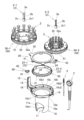
- FIG. 1 is an exploded perspective view of a Lillian knitting machine according to an embodiment of the present invention; 1 is a perspective view showing a state in which a lillian knitting member of a lillian knitting machine according to an embodiment of the present invention has been removed.
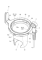
- FIG. 1 is a cross-sectional view of the Lillian knitting machine according to the embodiment of the present invention, in which the threading tool and the needle tool are omitted.
- FIG. 6 is a cross-sectional view of the Lillian knitting machine according to the embodiment of the present invention taken along the line VI-VI of FIG. 1, in which the threading tool and the needle tool are omitted.
- FIG. 2 is a bottom view of the Lillian knitting machine according to the embodiment of the present invention, in which the knitting machine body, the thread hooking device, and the needle device are omitted.
- 1 is a perspective view of a large knitting member and a small knitting member of a Lillian knitting machine according to an embodiment of the present invention, as viewed from below.
- FIG. FIG. 11 is a perspective view showing a state in which the Lillian knitting member of the Lillian knitting machine according to a modified example of the present invention has been removed.
- the lillian knitting machine 1 shown in Figs. 1 and 2 comprises a substantially cylindrical knitting machine body 10 and an annular lillian knitting member 50 rotatably mounted on the upper end of the knitting machine body 10.
- the lillian knitting member 50 is capable of performing lillian knitting by hanging yarn such as wool on pin members 2 arranged in an annular shape on the upper surface, and using a rod-shaped yarn hanging device 3 and a needle-shaped device 4.
- the lower side in Figs. 1 and 2 will be referred to as "down" and the upper side as "up.”
- the lillian knitting using the lillian knitting machine 1 can be done using a known knitting method.
- the end yarn is inserted from the upper center of the lillian knitting member 50 through the lillian outlet 11 (see Figure 3) at the bottom end of the knitting machine main body 10, and while holding down the end yarn, the yarn is wound around each pin member 2, and the original yarn side is hung on the yarn guide 12.
- the lillian knitting member 50 is then rotated once, and the lower side of the yarn that is attached above and below the pin member 2 is lifted by the tip of the yarn hook 3 and moved to the inner diameter side.
- the lillian knitting member 50 is rotated once again, and the yarns (lower yarns) hanging on all the pin members 2 are moved to the inner diameter side again.
- a lillian knitted lillian can be created.
- the lillian knitting member 50 can be attached to the knitting machine body 10 by replacing the large knitting member 50-1 shown in FIG. 1 with the small knitting member 50-2 shown in FIG. 2.
- the large knitting member 50-1 is provided with a pin member 2-1 for the large knitting member 50-1 as the pin member 2
- the small knitting member 50-2 is provided with a pin member 2-2 for the small knitting member 50-2.
- the diameter of the arrangement of the multiple pin members 2-1 is larger than the diameter of the arrangement of the multiple pin members 2-2. Therefore, the large knitting member 50-1 can knit a lillian knit with a larger diameter than the small knitting member 50-2.
- the knitting machine body 10 is formed in a generally cylindrical shape overall and is provided with a lower, generally cylindrical gripping portion 10a and a generally annular flange-shaped rotary joint receiving portion 10b that is provided above the gripping portion 10a and has a larger diameter than the gripping portion 10a.
- a generally circular lillian discharge port 11 is provided in the bottom plate 10a1 at the lower end of the gripping portion 10a.
- a side hole 11a is provided on the side of the gripping portion 10a, which is connected to the lillian discharge port 11 and passes through it.
- the lillian discharge port 11 and the side hole 11a are generally the same size.
- the side hole 11a allows the lillian knitting in the middle of production to be discharged from the lillian discharge outlet 11 to be passed through the side hole 11a, so even if the lillian knitting machine 1 is in the middle of production, the underside of the bottom plate 10a1 can be placed on a desk or the like and the machine can be temporarily placed in an upright position.
- a roughly annular circular wall portion 10c is provided on the outer edge of the rotary joint receiving portion 10b.
- a plurality of receiving ribs 10b1 are provided on the rotary joint receiving portion 10b.
- the receiving ribs 10b1 are provided in an L-shape across the upper surface 10b2 of the rotary joint receiving portion 10b and the inner surface 10c2 of the circular wall portion 10c.
- connection between the rotary joint receiving portion 10b and the circular wall portion 10c has four locking holes 10d that open along the circumferential direction and are spaced at equal intervals in the circumferential direction.
- the base end of the thread guide 12 is provided with a fixing portion 13 that is boss-shaped and has a through hole that penetrates in the vertical direction. The thread guide 12 can guide the thread by passing it between the two plate-like members.
- a fixed portion 14 that protrudes radially outward is provided on the side edge of the rotary joint receiving portion 10b that faces the thread guide 12 (fixed portion 13).
- the fixed portion 14 has a through hole that penetrates in the vertical direction. As shown in Figure 5, the fixed portions 13 and 14 have a countersunk shape on the lower side.
- a substantially annular rotary joint 20 is rotatably mounted on the rotary joint receiving portion 10b.
- a plurality of operating recesses 21 are provided on the outer circumferential surface of the rotary joint 20 at predetermined angular intervals in the circumferential direction.
- a substantially annular wall portion 24 is provided on the inner diameter side of the operating recesses 21.
- Two interlocking protrusions 22 that protrude inwardly and are provided opposite each other are provided on the inner circumferential surface of the annular wall portion 24 of the rotary joint 20.
- two rotation restricting protrusions 23 that protrude inwardly and are provided opposite the interlocking protrusions 22 at rotational positions that differ by 90 degrees are provided on the inner circumferential surface of the annular wall portion 24 of the rotary joint 20.
- the rotation restricting protrusion 23 includes a main restricting protrusion 23-1 that protrudes upward, and an auxiliary restricting protrusion 23-2 that protrudes inwardly to the same extent as the locked protrusion 22.
- a main restricting protrusion 23-1 that protrudes upward
- an auxiliary restricting protrusion 23-2 that protrudes inwardly to the same extent as the locked protrusion 22.
- the main restricting protrusion 23-1 protrudes from the upper surface of the annular wall portion 24, and the auxiliary restricting protrusion 23-2 and the locked protrusion 22 are provided continuously at approximately the same height as the upper surface of the annular wall portion 24.
- the lower surfaces of the locked protrusion 22 and the rotation restricting protrusion 23 are located above the lower surface of the annular wall portion 24.
- a groove 25 is formed between the operating recess 21 and the annular wall 24 of the rotary joint 20.
- the lower surface of the groove 25 abuts and slides against the receiving rib 10b1 of the rotary joint receiving portion 10b.
- the outer peripheral surface of the lower end side of the annular wall 24 (the outer peripheral surface of the lower end protrusion 26) slides against the inner diameter end of the receiving rib 10b1. This restricts radial movement of the rotary joint 20.
- annular resilient operating member 40 is provided around the fixed part 13 on the thread guide 12 side, which is the outer edge of the rotary joint receiving part 10b.
- the resilient operating member 40 is provided with an operating protrusion 41 that protrudes radially inward.
- a bifurcated locking part 42 is provided on the opposite side of the operating protrusion 41.
- the locking part 42 is locked to a locking rib 16 provided on the radially inner side at the base end of the thread guide 12 (see also Figure 7).
- the operating protrusion 41 is provided on a thin frame and is therefore resilient in the radial direction.
- the operating recesses 21 of the rotary joint 20 are provided corresponding to the multiple pin members 2.
- 12 pin members 2 are provided, and 12 operating recesses 21 are similarly provided corresponding to each pin member 2.
- the operating protrusions 41 of the operating resilient member 40 engage with the operating recesses 21.
- the operating protrusions 41 ride over the operating recesses 21 and engage with the operating recesses 21 on the opposite side to the direction of rotation. In this way, a clicking sensation can be obtained each time the Lillian knitting member 50 (rotary joint 20) rotates a predetermined angle.
- the fixing ring 30 is fixed to the knitting machine body 10 with a predetermined distance from the rotary joint receiving portion 10b.
- this predetermined distance is approximately the same as the height (thickness in the vertical direction) of the annular portion in which the operating recess 21 of the rotary joint 20 is provided, and more specifically, it is set to be slightly larger than the height of the annular portion in which the operating recess 21 of the rotary joint 20 is provided (i.e., to the extent that the rotary joint 20 can rotate).
- the fixing ring 30 is provided with four locking portions 31 that extend downward. The locking portions 31 are inserted into the locking holes 10d of the knitting machine body 10. As shown in FIGS.
- the outer edge of the fixing ring 30 abuts against the upper surface of the circular wall portion 10c of the knitting machine body 10.
- the knitting machine body 10 and the fixing ring 30 are fixed by screwing a screw member (not shown) from the underside of the fixing portions 13 and 14 and screwing into the corresponding female threaded portions of the fixing ring 30.
- the rotary joint 20 is rotatably mounted between the rotary joint receiving portion 10b and the fixed ring 30, and the vertical movement is restricted by fixing the fixed ring 30 to the knitting machine body 10.
- the resilient member holding portion 32 that protrudes radially from the fixed ring 30 is positioned above the operating resilient member 40, and the vertical movement of the operating resilient member 40 is restricted.
- a holding portion 33 that protrudes radially is provided on the edge of the fixing ring 30 that faces the spring member holding portion 32, and can hold the thread hook 3 and needle-shaped device 4.
- the Lillian knitting member 50 (large knitting member 50-1, small knitting member 50-2) is annular, and the inner diameter portion is provided with an annular wall portion 51 that extends downward in a substantially cylindrical shape.
- the Lillian knitting member 50 is detachably attached to the rotary joint 20 by fitting the annular wall portion 51 to the inner peripheral surface of the rotary joint 20. More specifically, the Lillian knitting member 50 is provided with two opposing locking portions 51a, each of which is provided with a locking protrusion 51a1 that protrudes radially outward from the tip by cutting out the annular wall portion 51. As shown in Figure 6, the locking protrusion 51a1 of the locking portion 51a locks with the locked protrusion 22 on the lower side. This restricts the Lillian knitting member 50 from moving up and down relative to the rotary joint 20.
- the annular wall portion 51 is also provided with two rotation restriction recesses 51b that are formed in a concave shape in the annular wall portion 51 and are provided opposite the rotation restriction protrusions 23 so that they can engage with the rotation restriction protrusions 23.
- the rotation restriction recesses 51b include a main rotation restriction recess 51b-1 that is provided in a concave shape in the up-down direction so that the annular wall portion 51 is divided in the circumferential direction, and an auxiliary rotation restriction recess 51b-2 that is provided in a concave shape in the inner diameter direction from the outer circumferential surface of the annular wall portion 51 and is open downward.
- the main rotation regulating recess 51b-1 is formed so as to be able to engage with the main regulating protrusion 23-1 of the rotary joint 20 by concave-convex engagement.
- the auxiliary rotation regulating recess 51b-2 is formed so as to be able to engage with the auxiliary regulating protrusion 23-2 of the rotary joint 20 by concave-convex engagement.
- the locking portion 51a formed by cutting out the annular wall portion 51 springs back and bends inward, releasing the locking state between the locking protrusion 51a1 and the locked protrusion 22, allowing the member to be removed.
- the rotation restricting recess 51b is aligned so that it engages with the rotation restricting protrusion 23, and the member is pushed in, thereby locking the locking protrusion 51a1 and the locked protrusion 22, and the Lillian knitting member 50 can be attached to the rotary joint 20.
- the large knitting member 50-1 has a plurality of pin member insertion portions 52 arranged in a ring shape on the radially outer side of the annular wall portion 51, into which a plurality of pin members 2 are inserted.
- the small knitting member 50-2 has a plurality of pin member insertion portions 52 arranged in a ring shape on the radially inner side of the annular wall portion 51.
- 12 pin member insertion portions 52 are provided in both the large knitting member 50-1 and the small knitting member 50-2.
- the pin member 2-1 for the large braided member 50-1 is formed with a larger diameter than the pin member 2-2 for the small braided member 50-2.
- the pin member 2 has a bulge 2a at the upper end, and the base end 2c is formed with a larger diameter than the shaft 2b.
- the bulge 2a of the pin member 2-1 for the large braided member 50-1 is formed in a four-leaf clover shape, and the bulge 2a of the pin member 2-2 for the small braided member 50-2 is formed in a star shape.
- the shaft 2b is formed in a cross shape in cross section.
- the base end 2c is provided with a key-shaped protrusion 2c1.
- the pin member insertion portion 52 of the Lillian braided member 50 is formed in a bottomed cylindrical shape, and a groove portion 52a corresponding to the protrusion 2c1 is formed to prevent the pin member 2 from rotating.
- the outer peripheral surface of the lillian knitting member 50 is circular and knurled. As shown in the enclosed diagram seen from the P direction in FIG. 1, the outer peripheral surface of the lillian knitting member 50 is provided with one marker portion 53 that protrudes in the shape of a four-leaf clover. The outer peripheral surface of the circular wall portion 10c of the knitting machine main body 10 is also provided with a marker portion 10c1 that protrudes in the shape of a clover and has the same shape as the marker portion 53 of the lillian knitting member 50.
- the small knitting member 50-2 has numbers 1 to 12 on its upper surface corresponding to the multiple pin members 2.
- the marker portion 53 is provided corresponding to the number "1" on the upper surface.
- the number of pin members 2 can be set to any number (up to 12 in this embodiment) simply by inserting the pin members 2 into the Lillian knitting members 50, so the mesh of the woven Lillian can be easily adjusted. And because the large knitting member 50-1 and the small knitting member 50-2 can be easily replaced, the Lillian knitting machine 1 can easily create multiple types of Lillians.
- the main rotation regulating recess 51b-1 engages with the main regulating protrusion 23-1
- the auxiliary rotation regulating recess 51b-2 engages with the auxiliary regulating protrusion 23-2. This allows the marker portion 53 to be positioned properly.
- the Lillian knitting member 50 is rotated 180 degrees to position the auxiliary rotation regulating recess 51b-2 so that it corresponds to the main regulating protrusion 23-1, and then the Lillian knitting member 50 is forcibly pushed in to bend the annular wall portion 51, the auxiliary rotation regulating recess 51b-2 may engage with the main regulating protrusion 23-1.
- a protrusion 23p is provided on the main regulating protrusion 23-1 of the rotary joint 20, which is a long protrusion extending in the vertical direction.
Landscapes
- Engineering & Computer Science (AREA)
- Textile Engineering (AREA)
- Knitting Machines (AREA)
Abstract
Le problème décrit par la présente invention est de fournir un dispositif de tricot français permettant la création facile d'une pluralité de types d'articles réalisés en tricot français. La solution selon l'invention porte sur un dispositif de tricot français 1 qui comprend : un corps de dispositif de tricot 10 ayant une portion de réception de charnière rotative 10b ; une bague fixe 30 fixée au corps de dispositif de tricot 10 ; une charnière rotative 20 disposée de manière rotative entre la portion de réception de charnière rotative 10b et la bague fixe 30 ; et un élément de tricot français 50 disposé de manière amovible sur la charnière rotative 20 et ayant une pluralité d'éléments de broche 2 disposés de manière amovible sur une surface supérieure. La surface périphérique interne de la charnière rotative 20 est pourvue de deux portions surélevées 22 à verrouiller, et deux portions surélevées de restriction de rotation 23 disposées l'une en face de l'autre à des positions de rotation différentes des portions surélevées 22 à verrouiller sur 90 degrés. L'élément de tricot français 50 est pourvu d'une portion de verrouillage 51a qui se verrouille sur les portions surélevées 22 à verrouiller, et de deux portions évidées de restriction de rotation 51b pouvant venir en prise avec les portions surélevées de restriction de rotation 23.
Applications Claiming Priority (4)
| Application Number | Priority Date | Filing Date | Title |
|---|---|---|---|
| JP2023093025 | 2023-06-06 | ||
| JP2023-093025 | 2023-06-06 | ||
| JP2023141115A JP2024175632A (ja) | 2023-06-06 | 2023-08-31 | リリアン編み機 |
| JP2023-141115 | 2023-08-31 |
Publications (1)
| Publication Number | Publication Date |
|---|---|
| WO2024252927A1 true WO2024252927A1 (fr) | 2024-12-12 |
Family
ID=93795473
Family Applications (1)
| Application Number | Title | Priority Date | Filing Date |
|---|---|---|---|
| PCT/JP2024/018801 Ceased WO2024252927A1 (fr) | 2023-06-06 | 2024-05-22 | Dispositif de tricot français |
Country Status (1)
| Country | Link |
|---|---|
| WO (1) | WO2024252927A1 (fr) |
Citations (3)
| Publication number | Priority date | Publication date | Assignee | Title |
|---|---|---|---|---|
| JP3064154U (ja) * | 1999-05-21 | 1999-12-24 | 株式会社バンダイ | 手編み装置 |
| JP2003171854A (ja) * | 2001-12-06 | 2003-06-20 | Clover Mfg Co Ltd | 編み具 |
| JP2017089078A (ja) * | 2015-11-10 | 2017-05-25 | 株式会社アガツマ | 手編み具 |
-
2024
- 2024-05-22 WO PCT/JP2024/018801 patent/WO2024252927A1/fr not_active Ceased
Patent Citations (3)
| Publication number | Priority date | Publication date | Assignee | Title |
|---|---|---|---|---|
| JP3064154U (ja) * | 1999-05-21 | 1999-12-24 | 株式会社バンダイ | 手編み装置 |
| JP2003171854A (ja) * | 2001-12-06 | 2003-06-20 | Clover Mfg Co Ltd | 編み具 |
| JP2017089078A (ja) * | 2015-11-10 | 2017-05-25 | 株式会社アガツマ | 手編み具 |
Similar Documents
| Publication | Publication Date | Title |
|---|---|---|
| US8074384B2 (en) | Auxiliary tool for handcrafting | |
| JP4578983B2 (ja) | スラッシュキルト用のカッターナイフ | |
| WO2024252927A1 (fr) | Dispositif de tricot français | |
| JP7349003B1 (ja) | コマ玩具 | |
| JP2024175632A (ja) | リリアン編み機 | |
| KR101294360B1 (ko) | 반짇고리 | |
| JP2003171854A (ja) | 編み具 | |
| CN206835481U (zh) | 一种拼弧机构以及显示屏 | |
| EP1873293A1 (fr) | Machine à coudre, bobine et boîte à canettes correspondante et utilisation | |
| US6745712B1 (en) | Fully rotatable shuttle | |
| US2924120A (en) | Cam-disk support device for sewing machines | |
| CN106676749B (zh) | 手工编织器 | |
| JP5950044B2 (ja) | 取り替え可能なボタン | |
| WO2006004243A1 (fr) | Dispositif a navette rotative avec corps de boite a canette partiellement ouvert pour machine a coudre | |
| JP5095314B2 (ja) | ミシン | |
| JPH0220227Y2 (fr) | ||
| US12180631B2 (en) | Indexable, locking hopping foot | |
| JP7630168B2 (ja) | 保持用部材及びこれを用いたスナップファスナー | |
| CN102162179B (zh) | 用于环接受器的梭壳移除和附连机构 | |
| JPH0251635B2 (fr) | ||
| JP2005261847A (ja) | ミシンのかまおよび外かま | |
| JP3099946U (ja) | ミシンの下糸供給装置 | |
| JP6071106B2 (ja) | スイッチ装置、時計、およびスイッチのロック解除方法 | |
| US2228627A (en) | Yarn carrier for hosiery knitting machines | |
| JP7363422B2 (ja) | 押え金の取付構造 |
Legal Events
| Date | Code | Title | Description |
|---|---|---|---|
| 121 | Ep: the epo has been informed by wipo that ep was designated in this application |
Ref document number: 24819160 Country of ref document: EP Kind code of ref document: A1 |
|
| NENP | Non-entry into the national phase |
Ref country code: DE |