WO2024252927A1 - リリアン編み機 - Google Patents
リリアン編み機 Download PDFInfo
- Publication number
- WO2024252927A1 WO2024252927A1 PCT/JP2024/018801 JP2024018801W WO2024252927A1 WO 2024252927 A1 WO2024252927 A1 WO 2024252927A1 JP 2024018801 W JP2024018801 W JP 2024018801W WO 2024252927 A1 WO2024252927 A1 WO 2024252927A1
- Authority
- WO
- WIPO (PCT)
- Prior art keywords
- lillian
- rotary joint
- knitting
- knitting machine
- annular wall
- Prior art date
- Legal status (The legal status is an assumption and is not a legal conclusion. Google has not performed a legal analysis and makes no representation as to the accuracy of the status listed.)
- Ceased
Links
Images


Classifications
-
- D—TEXTILES; PAPER
- D04—BRAIDING; LACE-MAKING; KNITTING; TRIMMINGS; NON-WOVEN FABRICS
- D04B—KNITTING
- D04B3/00—Hand tools or implements
Definitions
- the present invention relates to a Lillian knitting machine.
- Patent Document 1 describes a Lillian knitting machine that has a rotatable head at the top end of the knitting machine body and has a threading projection.
- the diameter and fineness of the finished lillian can be adjusted by changing the diameter and number of the thread-hanging protrusions arranged in a circular pattern.
- the above-mentioned conventional lillian knitting machine discloses a head with a different number of thread-hanging protrusions.
- the present invention aims to provide a lillian knitting machine that can easily create multiple types of lillians.
- the Lillian knitting machine of the present invention comprises a knitting machine main body having a cylindrical gripping portion provided with a Lillian discharge port, a rotary joint receiving portion formed in a flange shape at the upper end of the gripping portion, and a yarn guide erected from the side edge of the rotary joint receiving portion, a fixed ring fixed to the knitting machine main body with a predetermined distance from the rotary joint receiving portion, an annular rotary joint rotatably provided between the rotary joint receiving portion and the fixed ring, and a rotary joint rotatably provided between the rotary joint receiving portion and the fixed ring, the rotary joint rotatably provided in a ring shape, the inner diameter portion of which is formed with a ring-shaped wall portion extending downward in a roughly cylindrical shape, the ring-shaped wall portion being fitted to the inner peripheral surface of the rotary joint so as to be freely attached to and detached from the rotary joint, and a plurality of pins on the upper surface.
- the rotating joint has an inner peripheral surface provided with two interlocking protrusions that protrude inward from the inner peripheral surface and are provided opposite the interlocking protrusions at a rotational position that differs by 90 degrees
- the Lillian knitting member has two interlocking parts formed by cutting out the annular wall part, with interlocking protrusions at the tips that protrude outward from the diameter, and are provided opposite the interlocking protrusions so as to interlock with the interlocking protrusions at the lower side, and two rotation restricting recesses formed in the annular wall part in a concave shape and provided opposite the rotation restricting protrusions so as to be able to engage with them.
- FIG. 1 is a perspective view of a Lillian knitting machine according to an embodiment of the present invention, showing a state in which a large knitting member is attached.
- 1 is a perspective view of a Lillian knitting machine according to an embodiment of the present invention, showing a state in which a small knitting member is attached.
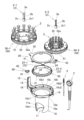
- FIG. 1 is an exploded perspective view of a Lillian knitting machine according to an embodiment of the present invention; 1 is a perspective view showing a state in which a lillian knitting member of a lillian knitting machine according to an embodiment of the present invention has been removed.
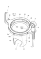
- FIG. 1 is a cross-sectional view of the Lillian knitting machine according to the embodiment of the present invention, in which the threading tool and the needle tool are omitted.
- FIG. 6 is a cross-sectional view of the Lillian knitting machine according to the embodiment of the present invention taken along the line VI-VI of FIG. 1, in which the threading tool and the needle tool are omitted.
- FIG. 2 is a bottom view of the Lillian knitting machine according to the embodiment of the present invention, in which the knitting machine body, the thread hooking device, and the needle device are omitted.
- 1 is a perspective view of a large knitting member and a small knitting member of a Lillian knitting machine according to an embodiment of the present invention, as viewed from below.
- FIG. FIG. 11 is a perspective view showing a state in which the Lillian knitting member of the Lillian knitting machine according to a modified example of the present invention has been removed.
- the lillian knitting machine 1 shown in Figs. 1 and 2 comprises a substantially cylindrical knitting machine body 10 and an annular lillian knitting member 50 rotatably mounted on the upper end of the knitting machine body 10.
- the lillian knitting member 50 is capable of performing lillian knitting by hanging yarn such as wool on pin members 2 arranged in an annular shape on the upper surface, and using a rod-shaped yarn hanging device 3 and a needle-shaped device 4.
- the lower side in Figs. 1 and 2 will be referred to as "down" and the upper side as "up.”
- the lillian knitting using the lillian knitting machine 1 can be done using a known knitting method.
- the end yarn is inserted from the upper center of the lillian knitting member 50 through the lillian outlet 11 (see Figure 3) at the bottom end of the knitting machine main body 10, and while holding down the end yarn, the yarn is wound around each pin member 2, and the original yarn side is hung on the yarn guide 12.
- the lillian knitting member 50 is then rotated once, and the lower side of the yarn that is attached above and below the pin member 2 is lifted by the tip of the yarn hook 3 and moved to the inner diameter side.
- the lillian knitting member 50 is rotated once again, and the yarns (lower yarns) hanging on all the pin members 2 are moved to the inner diameter side again.
- a lillian knitted lillian can be created.
- the lillian knitting member 50 can be attached to the knitting machine body 10 by replacing the large knitting member 50-1 shown in FIG. 1 with the small knitting member 50-2 shown in FIG. 2.
- the large knitting member 50-1 is provided with a pin member 2-1 for the large knitting member 50-1 as the pin member 2
- the small knitting member 50-2 is provided with a pin member 2-2 for the small knitting member 50-2.
- the diameter of the arrangement of the multiple pin members 2-1 is larger than the diameter of the arrangement of the multiple pin members 2-2. Therefore, the large knitting member 50-1 can knit a lillian knit with a larger diameter than the small knitting member 50-2.
- the knitting machine body 10 is formed in a generally cylindrical shape overall and is provided with a lower, generally cylindrical gripping portion 10a and a generally annular flange-shaped rotary joint receiving portion 10b that is provided above the gripping portion 10a and has a larger diameter than the gripping portion 10a.
- a generally circular lillian discharge port 11 is provided in the bottom plate 10a1 at the lower end of the gripping portion 10a.
- a side hole 11a is provided on the side of the gripping portion 10a, which is connected to the lillian discharge port 11 and passes through it.
- the lillian discharge port 11 and the side hole 11a are generally the same size.
- the side hole 11a allows the lillian knitting in the middle of production to be discharged from the lillian discharge outlet 11 to be passed through the side hole 11a, so even if the lillian knitting machine 1 is in the middle of production, the underside of the bottom plate 10a1 can be placed on a desk or the like and the machine can be temporarily placed in an upright position.
- a roughly annular circular wall portion 10c is provided on the outer edge of the rotary joint receiving portion 10b.
- a plurality of receiving ribs 10b1 are provided on the rotary joint receiving portion 10b.
- the receiving ribs 10b1 are provided in an L-shape across the upper surface 10b2 of the rotary joint receiving portion 10b and the inner surface 10c2 of the circular wall portion 10c.
- connection between the rotary joint receiving portion 10b and the circular wall portion 10c has four locking holes 10d that open along the circumferential direction and are spaced at equal intervals in the circumferential direction.
- the base end of the thread guide 12 is provided with a fixing portion 13 that is boss-shaped and has a through hole that penetrates in the vertical direction. The thread guide 12 can guide the thread by passing it between the two plate-like members.
- a fixed portion 14 that protrudes radially outward is provided on the side edge of the rotary joint receiving portion 10b that faces the thread guide 12 (fixed portion 13).
- the fixed portion 14 has a through hole that penetrates in the vertical direction. As shown in Figure 5, the fixed portions 13 and 14 have a countersunk shape on the lower side.
- a substantially annular rotary joint 20 is rotatably mounted on the rotary joint receiving portion 10b.
- a plurality of operating recesses 21 are provided on the outer circumferential surface of the rotary joint 20 at predetermined angular intervals in the circumferential direction.
- a substantially annular wall portion 24 is provided on the inner diameter side of the operating recesses 21.
- Two interlocking protrusions 22 that protrude inwardly and are provided opposite each other are provided on the inner circumferential surface of the annular wall portion 24 of the rotary joint 20.
- two rotation restricting protrusions 23 that protrude inwardly and are provided opposite the interlocking protrusions 22 at rotational positions that differ by 90 degrees are provided on the inner circumferential surface of the annular wall portion 24 of the rotary joint 20.
- the rotation restricting protrusion 23 includes a main restricting protrusion 23-1 that protrudes upward, and an auxiliary restricting protrusion 23-2 that protrudes inwardly to the same extent as the locked protrusion 22.
- a main restricting protrusion 23-1 that protrudes upward
- an auxiliary restricting protrusion 23-2 that protrudes inwardly to the same extent as the locked protrusion 22.
- the main restricting protrusion 23-1 protrudes from the upper surface of the annular wall portion 24, and the auxiliary restricting protrusion 23-2 and the locked protrusion 22 are provided continuously at approximately the same height as the upper surface of the annular wall portion 24.
- the lower surfaces of the locked protrusion 22 and the rotation restricting protrusion 23 are located above the lower surface of the annular wall portion 24.
- a groove 25 is formed between the operating recess 21 and the annular wall 24 of the rotary joint 20.
- the lower surface of the groove 25 abuts and slides against the receiving rib 10b1 of the rotary joint receiving portion 10b.
- the outer peripheral surface of the lower end side of the annular wall 24 (the outer peripheral surface of the lower end protrusion 26) slides against the inner diameter end of the receiving rib 10b1. This restricts radial movement of the rotary joint 20.
- annular resilient operating member 40 is provided around the fixed part 13 on the thread guide 12 side, which is the outer edge of the rotary joint receiving part 10b.
- the resilient operating member 40 is provided with an operating protrusion 41 that protrudes radially inward.
- a bifurcated locking part 42 is provided on the opposite side of the operating protrusion 41.
- the locking part 42 is locked to a locking rib 16 provided on the radially inner side at the base end of the thread guide 12 (see also Figure 7).
- the operating protrusion 41 is provided on a thin frame and is therefore resilient in the radial direction.
- the operating recesses 21 of the rotary joint 20 are provided corresponding to the multiple pin members 2.
- 12 pin members 2 are provided, and 12 operating recesses 21 are similarly provided corresponding to each pin member 2.
- the operating protrusions 41 of the operating resilient member 40 engage with the operating recesses 21.
- the operating protrusions 41 ride over the operating recesses 21 and engage with the operating recesses 21 on the opposite side to the direction of rotation. In this way, a clicking sensation can be obtained each time the Lillian knitting member 50 (rotary joint 20) rotates a predetermined angle.
- the fixing ring 30 is fixed to the knitting machine body 10 with a predetermined distance from the rotary joint receiving portion 10b.
- this predetermined distance is approximately the same as the height (thickness in the vertical direction) of the annular portion in which the operating recess 21 of the rotary joint 20 is provided, and more specifically, it is set to be slightly larger than the height of the annular portion in which the operating recess 21 of the rotary joint 20 is provided (i.e., to the extent that the rotary joint 20 can rotate).
- the fixing ring 30 is provided with four locking portions 31 that extend downward. The locking portions 31 are inserted into the locking holes 10d of the knitting machine body 10. As shown in FIGS.
- the outer edge of the fixing ring 30 abuts against the upper surface of the circular wall portion 10c of the knitting machine body 10.
- the knitting machine body 10 and the fixing ring 30 are fixed by screwing a screw member (not shown) from the underside of the fixing portions 13 and 14 and screwing into the corresponding female threaded portions of the fixing ring 30.
- the rotary joint 20 is rotatably mounted between the rotary joint receiving portion 10b and the fixed ring 30, and the vertical movement is restricted by fixing the fixed ring 30 to the knitting machine body 10.
- the resilient member holding portion 32 that protrudes radially from the fixed ring 30 is positioned above the operating resilient member 40, and the vertical movement of the operating resilient member 40 is restricted.
- a holding portion 33 that protrudes radially is provided on the edge of the fixing ring 30 that faces the spring member holding portion 32, and can hold the thread hook 3 and needle-shaped device 4.
- the Lillian knitting member 50 (large knitting member 50-1, small knitting member 50-2) is annular, and the inner diameter portion is provided with an annular wall portion 51 that extends downward in a substantially cylindrical shape.
- the Lillian knitting member 50 is detachably attached to the rotary joint 20 by fitting the annular wall portion 51 to the inner peripheral surface of the rotary joint 20. More specifically, the Lillian knitting member 50 is provided with two opposing locking portions 51a, each of which is provided with a locking protrusion 51a1 that protrudes radially outward from the tip by cutting out the annular wall portion 51. As shown in Figure 6, the locking protrusion 51a1 of the locking portion 51a locks with the locked protrusion 22 on the lower side. This restricts the Lillian knitting member 50 from moving up and down relative to the rotary joint 20.
- the annular wall portion 51 is also provided with two rotation restriction recesses 51b that are formed in a concave shape in the annular wall portion 51 and are provided opposite the rotation restriction protrusions 23 so that they can engage with the rotation restriction protrusions 23.
- the rotation restriction recesses 51b include a main rotation restriction recess 51b-1 that is provided in a concave shape in the up-down direction so that the annular wall portion 51 is divided in the circumferential direction, and an auxiliary rotation restriction recess 51b-2 that is provided in a concave shape in the inner diameter direction from the outer circumferential surface of the annular wall portion 51 and is open downward.
- the main rotation regulating recess 51b-1 is formed so as to be able to engage with the main regulating protrusion 23-1 of the rotary joint 20 by concave-convex engagement.
- the auxiliary rotation regulating recess 51b-2 is formed so as to be able to engage with the auxiliary regulating protrusion 23-2 of the rotary joint 20 by concave-convex engagement.
- the locking portion 51a formed by cutting out the annular wall portion 51 springs back and bends inward, releasing the locking state between the locking protrusion 51a1 and the locked protrusion 22, allowing the member to be removed.
- the rotation restricting recess 51b is aligned so that it engages with the rotation restricting protrusion 23, and the member is pushed in, thereby locking the locking protrusion 51a1 and the locked protrusion 22, and the Lillian knitting member 50 can be attached to the rotary joint 20.
- the large knitting member 50-1 has a plurality of pin member insertion portions 52 arranged in a ring shape on the radially outer side of the annular wall portion 51, into which a plurality of pin members 2 are inserted.
- the small knitting member 50-2 has a plurality of pin member insertion portions 52 arranged in a ring shape on the radially inner side of the annular wall portion 51.
- 12 pin member insertion portions 52 are provided in both the large knitting member 50-1 and the small knitting member 50-2.
- the pin member 2-1 for the large braided member 50-1 is formed with a larger diameter than the pin member 2-2 for the small braided member 50-2.
- the pin member 2 has a bulge 2a at the upper end, and the base end 2c is formed with a larger diameter than the shaft 2b.
- the bulge 2a of the pin member 2-1 for the large braided member 50-1 is formed in a four-leaf clover shape, and the bulge 2a of the pin member 2-2 for the small braided member 50-2 is formed in a star shape.
- the shaft 2b is formed in a cross shape in cross section.
- the base end 2c is provided with a key-shaped protrusion 2c1.
- the pin member insertion portion 52 of the Lillian braided member 50 is formed in a bottomed cylindrical shape, and a groove portion 52a corresponding to the protrusion 2c1 is formed to prevent the pin member 2 from rotating.
- the outer peripheral surface of the lillian knitting member 50 is circular and knurled. As shown in the enclosed diagram seen from the P direction in FIG. 1, the outer peripheral surface of the lillian knitting member 50 is provided with one marker portion 53 that protrudes in the shape of a four-leaf clover. The outer peripheral surface of the circular wall portion 10c of the knitting machine main body 10 is also provided with a marker portion 10c1 that protrudes in the shape of a clover and has the same shape as the marker portion 53 of the lillian knitting member 50.
- the small knitting member 50-2 has numbers 1 to 12 on its upper surface corresponding to the multiple pin members 2.
- the marker portion 53 is provided corresponding to the number "1" on the upper surface.
- the number of pin members 2 can be set to any number (up to 12 in this embodiment) simply by inserting the pin members 2 into the Lillian knitting members 50, so the mesh of the woven Lillian can be easily adjusted. And because the large knitting member 50-1 and the small knitting member 50-2 can be easily replaced, the Lillian knitting machine 1 can easily create multiple types of Lillians.
- the main rotation regulating recess 51b-1 engages with the main regulating protrusion 23-1
- the auxiliary rotation regulating recess 51b-2 engages with the auxiliary regulating protrusion 23-2. This allows the marker portion 53 to be positioned properly.
- the Lillian knitting member 50 is rotated 180 degrees to position the auxiliary rotation regulating recess 51b-2 so that it corresponds to the main regulating protrusion 23-1, and then the Lillian knitting member 50 is forcibly pushed in to bend the annular wall portion 51, the auxiliary rotation regulating recess 51b-2 may engage with the main regulating protrusion 23-1.
- a protrusion 23p is provided on the main regulating protrusion 23-1 of the rotary joint 20, which is a long protrusion extending in the vertical direction.
Landscapes
- Engineering & Computer Science (AREA)
- Textile Engineering (AREA)
- Knitting Machines (AREA)
Abstract
【課題】複数種類のリリアンを容易に作成することができるリリアン編み機を提供する。 【解決手段】リリアン編み機1は、回転ジョイント受部10bを有する編み機本体10と、編み機本体10に固定される固定リング30と、回転ジョイント受部10bと固定リング30との間に回転可能に設けられる回転ジョイント20と、回転ジョイント20に着脱自在に設けられ、上面には複数のピン部材2が着脱自在に設けられるリリアン編部材50と、を有し、回転ジョイント20の内周面には、2個の被係止凸部22と、被係止凸部22と90度異なる回転位置に対向して設けられる2個の回転規制凸部23と、が設けられ、リリアン編部材50は、被係止凸部22と係止する係止部51aと、回転規制凸部23と係合可能な2個の回転規制凹部51bと、が設けられる。
Description
本発明は、リリアン編み機に関する。
従来から、リリアンを容易に編み込むことができるリリアン編み機が提供されている。例えば、特許文献1には、糸掛け用突起を備えて編み機本体の上端に回転可能なヘッドが設けられたリリアン編み機が記載されている。
リリアン編み機により作成できるリリアンは、円環状に配置される糸掛け用突起の配置直径やその数を変更することで、編み上がるリリアンの直径や網目の細かさを調整することができる。上記従来のリリアン編み機では、糸掛け用突起の本数を異ならせたヘッドが開示されている。
リリアン編み機で編み上がるリリアンの直径や網目の細かさを変更して、より多くの種類のリリアンを作成したい要望がある。しかしながら、糸掛け用突起の本数を異ならせた複数種類のヘッドを用意しておくのは煩雑であり、例えば子供が使用する場合には使い方が分かり難くなってしまうことがあった。
本発明は、複数種類のリリアンを容易に作成することができるリリアン編み機を提供することを目的とする。
本発明に係るリリアン編み機は、リリアン排出口が設けられ円筒状に形成される把持部と、前記把持部の上端にフランジ状に形成される回転ジョイント受部と、前記回転ジョイント受部の側縁から立設する糸ガイドと、を有する編み機本体と、前記回転ジョイント受部と所定間隔を有して前記編み機本体に固定される固定リングと、前記回転ジョイント受部と前記固定リングとの間に回転可能に設けられる環状の回転ジョイントと、環状に設けられ、内径部は略筒状に下方に伸びる環状壁部が形成されて前記環状壁部が前記回転ジョイントの内周面に嵌合することで前記回転ジョイントに着脱自在に設けられ、上面には複数のピン部材が着脱自在に設けられるリリアン編部材と、を有し、前記回転ジョイントの内周面には、前記内周面から内径方向に突出し対向して設けられる2個の被係止凸部と、前記内周面から内径方向に突出し前記被係止凸部と90度異なる回転位置に対向して設けられる2個の回転規制凸部と、が設けられ、前記リリアン編部材は、前記環状壁部が切り欠かれて形成され先端に径外方向に突出する係止突起が形成され前記被係止凸部と下側で係止するよう対向して設けられる2個の係止部と、前記環状壁部に凹状に形成されて前記回転規制凸部と係合可能に対向して設けられる2個の回転規制凹部と、が設けられる、ことを特徴とする。
本発明によれば、複数種類のリリアンを容易に作成することができる。
本発明の実施形態を図に基づいて説明する。図1及び図2に示すリリアン編み機1は、略円筒状の編み機本体10と、編み機本体10の上端に回転可能に設けられる円環状のリリアン編部材50を備える。リリアン編部材50は、上面に円環状に配置されるピン部材2に、毛糸等の糸を掛け、棒状の糸掛け具3や針状具4を用いてリリアン編みを行うことができるものである。なお、以下の説明においては、図1、図2における下側を下、上側を上とする。
リリアン編み機1によるリリアン編みは、公知の編み方で編み込むことができる。簡単に説明すると、端糸をリリアン編部材50の中央上方から、編み機本体10下端のリリアン排出口11(図3参照)に挿通させて、端糸を押さえながら各ピン部材2に糸を巻回して、元糸側を糸ガイド12に掛ける。そして、リリアン編部材50を1回転させて、ピン部材2に上下に係る糸の下側を糸掛け具3の先端で持ち上げて内径側に移動させる。すべてのピン部材2に掛かる糸(下側の糸)を内径側に移動させたら、リリアン編部材50を再び1回転させて、再びすべてのピン部材2に掛かる糸(下側の糸)を内径側に移動させる。この作業を繰り返すことで、リリアン編みされたリリアンを作成することができる。
リリアン編部材50は、図1に示す大編部材50-1と、図2に示す小編部材50-2とを編み機本体10に対して交換して装着することができる。大編部材50-1には、ピン部材2として、大編部材50-1用のピン部材2-1が設けられ、小編部材50-2には、小編部材50-2用のピン部材2-2が設けられる。複数のピン部材2-1の配置の直径は、複数のピン部材2-2の配置の直径よりも大きい。従って、大編部材50-1では、小編部材50-2よりも大きい直径のリリアン編みをすることができる。
図3に示すように、編み機本体10は、全体が略円筒状に形成され、下側の略円筒状の把持部10aと、把持部10aの上側に設けられて把持部10aよりも径大に形成されるフランジ状であって略円環状の回転ジョイント受部10bが設けられる。把持部10aの下端の底板10a1には、略円形に開口するリリアン排出口11が設けられる。把持部10aの側面部には、リリアン排出口11と連通して貫通する側孔部11aが設けられる。リリアン排出口11と側孔部11aは、略同じ大きさとされている。
側孔部11aは、リリアン排出口11から排出される製作途中のリリアン編みをリリアン排出口11から側孔部11aに通すことで、側方に編み込みしたリリアン編みを排出することができるので、製作途中のであっても、底板10a1の下面を机上等に載置してリリアン編み機1を立てた状態で一時置いておくことができる。
回転ジョイント受部10bの外縁には、略円環状の円壁部10cが設けられている。回転ジョイント受部10bには、複数の受リブ10b1が設けられている。受リブ10b1は、回転ジョイント受部10bの上面10b2と、円壁部10cの内面10c2と、に亘ってL字状に設けられている。
回転ジョイント受部10bと円壁部10cとの接続部分には、円周方向に沿って開口する係止孔部10dが円周方向等間隔に4か所設けられている。また、糸ガイド12の基端部には、ボス状に設けられて上下方向に貫通する貫通孔を備える固定部13が設けられている。糸ガイド12は、2枚の板状部材の間に糸を通して糸をガイドすることができる。
糸ガイド12(固定部13)に対向する回転ジョイント受部10bの側縁には、径外方向に突出する固定部14が設けられている。固定部14は、上下方向に貫通する貫通孔を備える。図5に示すように、固定部13,14は、下側が座繰り状とされている。
図3に戻り、回転ジョイント受部10bには、略円環状の回転ジョイント20が回転可能に設けられる。回転ジョイント20の外周面には、複数の操作用凹部21が周方向所定角度間隔で設けられている。操作用凹部21より内径側には、略円環状の環状壁部24が設けられている。回転ジョイント20の環状壁部24の内周面には、内径方向に突出し対向して設けられる2個の被係止凸部22が設けられる。また、回転ジョイント20の環状壁部24の内周面には、内径方向に突出し、被係止凸部22と90度異なる回転位置に対向して設けられる2個の回転規制凸部23が設けられている。
回転規制凸部23は、上方に突出する主規制凸部23-1と、被係止凸部22と同程度に内径方向に突出する補助規制凸部23-2とを含む。被係止凸部22及び回転規制凸部23の各上面は、主規制凸部23-1のみ環状壁部24の上面から突出し、補助規制凸部23-2及び被係止凸部22は、環状壁部24の上面と略同じ高さで連続して設けられている。被係止凸部22及び回転規制凸部23の下面は、環状壁部24の下面よりも上側に位置している。
図5に示すように、回転ジョイント20の操作用凹部21と環状壁部24との間には、溝部25が形成される。そして、溝部25の下側の下面は、回転ジョイント受部10bの受リブ10b1に当接し、摺接する。環状壁部24の下端側の外周面(下端突出部26の外周面)は、受リブ10b1の内径端と摺接する。これにより、回転ジョイント20は、径方向の移動が規制されている。
図3に戻り、回転ジョイント受部10bの外縁である糸ガイド12側の固定部13周りには、環状の操作用弾発部材40が設けられる。操作用弾発部材40は、径方向内側に向けて突出する操作用凸部41が設けられている。操作用凸部41の反対側には、二股状の係止部42が設けられている。係止部42は、糸ガイド12の基端部における径方向内側に設けられる係止リブ16に係止される(図7も参照)。操作用凸部41は、薄肉のフレーム上に設けられているので、径方向に弾発されている。
ここで、回転ジョイント20の操作用凹部21は、複数のピン部材2に対応して設けられている。本実施形態においては、ピン部材2は、12個設けられており、操作用凹部21は、各ピン部材2に対応して、同じように12個設けられている。そして、図7に示すように、操作用弾発部材40の操作用凸部41は、操作用凹部21に係合する。回転ジョイント20が回転すると、操作用凸部41は操作用凹部21を乗り越えて、回転方向と逆側の操作用凹部21と係合する。このようにして、リリアン編部材50(回転ジョイント20)が所定角度回転する毎にクリック感を得ることができる。
図3に戻り、固定リング30は、回転ジョイント受部10bと所定間隔を有して編み機本体10に固定される。この所定間隔は、本実施形態では、回転ジョイント20の操作用凹部21が設けられる環状部分の高さ(上下方向の厚み)と略同じであって、より具体的には、回転ジョイント20の操作用凹部21が設けられる環状部分の高さよりも若干大きく(すなわち、回転ジョイント20が回転可能な程度に)設定されている。固定リング30は、下方に伸びる4個の係止部31が設けられている。係止部31は、編み機本体10の係止孔部10dに挿入される。図5,6に示すように、固定リング30は、外側の縁部が編み機本体10の円壁部10cの上面と当接する。編み機本体10と固定リング30は、固定部13,14の下側からねじ部材(不図示)がねじ込まれ、固定リング30の対応する雌ねじ部と螺合されることで固定されている。
回転ジョイント20は、回転ジョイント受部10bと固定リング30との間に回転可能に設けられて、編み機本体10に固定リング30が固定されることにより、上下方向の移動が規制される。同様に、固定リング30から径方向に突出する弾発部材押さえ部32は操作用弾発部材40の上方に位置して、操作用弾発部材40の上下方向の移動が規制される。
なお、固定リング30における弾発部材押さえ部32の対向する縁部には、径方向に突出する保持部33が設けられ、糸掛け具3や針状具4を保持することができる。
図3及び図8も参照して、リリアン編部材50(大編部材50-1、小編部材50-2)は、環状に設けられ、内径部には略円筒状に下方に伸びる環状壁部51が設けられている。リリアン編部材50は、環状壁部51が回転ジョイント20の内周面に嵌合することで回転ジョイント20に着脱可能に設けられている。より具体的には、リリアン編部材50は、環状壁部51が切り欠かれて先端に径外方向に突出する係止突起51a1を備える係止部51aが対向して2個設けられている。図6に示すように、係止部51aの係止突起51a1は、被係止凸部22と下側で係止する。これにより、リリアン編部材50は、回転ジョイント20に対して上下方向の移動が規制される。
また、環状壁部51には、環状壁部51に凹状に形成されて回転規制凸部23と係合可能に対向して設けられる2個の回転規制凹部51bが設けられている。回転規制凹部51bは、環状壁部51が周方向に分割されるよう上下方向に凹状に設けられる主回転規制凹部51b-1と、環状壁部51の外周面から内径方向に凹状に設けられ下方が開放された補助回転規制凹部51b-2が設けられる。
図5及び図6に示すように、主回転規制凹部51b-1は、回転ジョイント20の主規制凸部23-1と凹凸係合により係合可能に形成される。また、補助回転規制凹部51b-2は、回転ジョイント20の補助規制凸部23-2と凹凸係合により係合可能に形成される。回転規制凹部51bと回転規制凸部23の係合により、リリアン編部材50は、回転ジョイント20に対して回転方向に相対的に固定される。これにより、リリアン編部材50は、回転ジョイント20と共に回転することができる。
このようにして、リリアン編部材50は、回転ジョイント20に係合している状態から上方に引き抜くと、環状壁部51を切り欠いて形成される係止部51aが弾発して内径側に撓むことで、係止突起51a1と被係止凸部22の係止状態が解除され、取り外すことができる。反対に、装着する際には、回転規制凹部51bと回転規制凸部23が係合するように位置合わせして押し込むことで、係止突起51a1と被係止凸部22を係止させる、リリアン編部材50を回転ジョイント20に装着することができる。
リリアン編部材50のうち、大編部材50-1は、環状壁部51の径方向外側に複数のピン部材2が挿入される複数のピン部材挿入部52が環状に設けられる。一方、小編部材50-2は、環状壁部51の径方向内側に複数のピン部材挿入部52が環状に設けられる。本実施形態においては、ピン部材挿入部52は、大編部材50-1、小編部材50-2共に、12個設けられている。
ここで、ピン部材2は、大編部材50-1用のピン部材2-1の方が、小編部材50-2のピン部材2-2よりも大径に形成される。ピン部材2は、上端に膨出部2aが設けられ、基端部2cは、軸部2bよりも大径とされている。大編部材50-1用のピン部材2-1の膨出部2aは、四葉のクローバー状に形成され、小編部材50-2用のピン部材2-2の膨出部2aは、星形に形成される。軸部2bは横断面視十字状に形成される。基端部2cには、キー状の突条2c1が設けられている。リリアン編部材50のピン部材挿入部52は、有底円筒状に形成されて、突条2c1に対応した溝部52aが形成され、ピン部材2の周り止めがされている。
リリアン編部材50の外周面は、円壁状とされ、ローレットが施されている。リリアン編部材50の外周面には、図1のP方向から見た囲み図に示すように、四葉のクローバー状に突出する目印部53が1つ設けられている。編み機本体10の円壁部10cの外周面にも1つのクローバー状に突出する、リリアン編部材50の目印部53と同形状の目印部10c1が設けられている。小編部材50-2には、上面に、複数のピン部材2に対応して、1~12の数字が設けられる。そして、目印部53は、上面の数字の「1」に対応して設けられている。目印部53,10c1を合わせて糸を掛けて、リリアン編部材50を回転させることで、リリアン編部材50がどの程度回転したか分かりやすくされている。
リリアン編み機1によれば、リリアン編部材50にピン部材2を差し込むだけで、ピン部材2を任意の本数(本実施形態においては12本まで)とすることができるので、容易に編み込むリリアンの網目を調整することができる。そして、大編部材50-1と小編部材50-2を容易に交換できるので、リリアン編み機1は、複数種類のリリアンを容易に作成することができる。
前述の通り、リリアン編部材50は、主回転規制凹部51b-1と主規制凸部23-1が係合し、補助回転規制凹部51b-2と補助規制凸部23-2が係合する。これにより、目印部53を適正に配置することができる。しかしながら、リリアン編部材50を180度回転させて補助回転規制凹部51b-2が主規制凸部23-1に対応するよう配置し、無理にリリアン編部材50を押し込み、環状壁部51を撓ませることで、補助回転規制凹部51b-2と主規制凸部23-1が係合してしまうことがある。
そこで、回転ジョイント20の変形例に係る図9に示すように、回転ジョイント20の主規制凸部23-1に、上下方向に長い凸条として設けられる突起部23pを設けた。これにより、補助回転規制凹部51b-2が主規制凸部23-1に対応するよう配置され、無理にリリアン編部材50が押し込まれたとしても、突起部23pが環状壁部51に当接し、不適正な位置でリリアン編部材50が回転ジョイント20に装着されることが低減される。
以上、本発明の実施形態を説明したが、本発明は本実施形態によって限定されることはなく、種々の変更を加えて実施することができる。
1 リリアン編み機 2 ピン部材
2a 膨出部 2b 軸部
2c 基端部 2c1 突条
3 糸掛け具 4 針状具
10 機本体 10a 把持部
10a1 底板 10b 回転ジョイント受部
10b1 受リブ 10b2 上面
10c 円壁部 10c1 目印部
10c2 内面 10d 係止孔部
11 リリアン排出口 11a 側孔部
12 糸ガイド 13 固定部
14 固定部 16 係止リブ
20 回転ジョイント 21 操作用凹部
22 被係止凸部 23 回転規制凸部
23-1 主規制凸部 23-2 補助規制凸部
23p 突起部
24 環状壁部 25 溝部
26 下端突出部 30 固定リング
31 係止部 32 弾発部材押さえ部
33 保持部 40 操作用弾発部材
41 操作用凸部 42 係止部
50 リリアン編部材 50-1 大編部材
50-2 小編部材 51 環状壁部
51a 係止部 51a1 係止突起
51b 回転規制凹部 51b-1 主回転規制凹部
51b-2 補助回転規制凹部 52 ピン部材挿入部
52a 溝部 53 目印部
Claims (7)
- リリアン排出口が設けられ円筒状に形成される把持部と、前記把持部の上端にフランジ状に形成される回転ジョイント受部と、前記回転ジョイント受部の側縁から立設する糸ガイドと、を有する編み機本体と、
前記回転ジョイント受部と所定間隔を有して前記編み機本体に固定される固定リングと、
前記回転ジョイント受部と前記固定リングとの間に回転可能に設けられる環状の回転ジョイントと、
環状に設けられ、内径部は略筒状に下方に伸びる環状壁部が形成されて前記環状壁部が前記回転ジョイントの内周面に嵌合することで前記回転ジョイントに着脱自在に設けられ、上面には複数のピン部材が着脱自在に設けられるリリアン編部材と、
を有し、
前記回転ジョイントの前記内周面には、前記内周面から内径方向に突出し対向して設けられる2個の被係止凸部と、前記内周面から内径方向に突出し前記被係止凸部と90度異なる回転位置に対向して設けられる2個の回転規制凸部と、が設けられ、
前記リリアン編部材は、前記環状壁部が切り欠かれて形成され先端に径外方向に突出する係止突起が形成され前記被係止凸部と下側で係止するよう対向して設けられる2個の係止部と、前記環状壁部に凹状に形成されて前記回転規制凸部と係合可能に対向して設けられる2個の回転規制凹部と、が設けられる、
ことを特徴とするリリアン編み機。 - 前記回転規制凸部は、上方に突出する主規制凸部と、前記被係止凸部と同程度に内径方向に突出する補助規制凸部と、を有し、
前記回転規制凹部は、前記環状壁部が分割されるように上下方向に凹状に設けられ前記主規制凸部と係合可能に形成される主回転規制凹部と、前記環状壁部の外周面から内径方向に凹状に設けられ下方が開放され前記補助規制凸部と係合可能に形成される補助回転規制凹部と、
を有することを特徴とする請求項1に記載のリリアン編み機。 - 前記回転ジョイント受部は、円周方向に複数設けられるL字状の受リブが設けられていることを特徴とする請求項1に記載のリリアン編み機。
- 前記回転ジョイントの外周面には、複数の操作用凹部が各前記ピン部材に対応して周方向所定角度間隔で設けられ、
前記回転ジョイント受部の外縁には、前記操作用凹部と係合可能な操作用凸部が径方向に弾発されて設けられる操作用弾発部材と、
を有することを特徴とする請求項1に記載のリリアン編み機。 - 前記操作用弾発部材は、環状に形成されることを特徴とする請求項4に記載のリリアン編み機。
- 前記リリアン編部材は、前記環状壁部の径方向外側に前記複数のピン部材が挿入される複数のピン部材挿入部を備えることを特徴とする請求項1に記載のリリアン編み機。
- 前記リリアン編部材は、前記環状壁部の径方向内側に前記複数のピン部材が挿入される複数のピン部材挿入部を備えることを特徴とする請求項1に記載のリリアン編み機。
Applications Claiming Priority (4)
| Application Number | Priority Date | Filing Date | Title |
|---|---|---|---|
| JP2023-093025 | 2023-06-06 | ||
| JP2023093025 | 2023-06-06 | ||
| JP2023-141115 | 2023-08-31 | ||
| JP2023141115A JP2024175632A (ja) | 2023-06-06 | 2023-08-31 | リリアン編み機 |
Publications (1)
| Publication Number | Publication Date |
|---|---|
| WO2024252927A1 true WO2024252927A1 (ja) | 2024-12-12 |
Family
ID=93795473
Family Applications (1)
| Application Number | Title | Priority Date | Filing Date |
|---|---|---|---|
| PCT/JP2024/018801 Ceased WO2024252927A1 (ja) | 2023-06-06 | 2024-05-22 | リリアン編み機 |
Country Status (1)
| Country | Link |
|---|---|
| WO (1) | WO2024252927A1 (ja) |
Citations (3)
| Publication number | Priority date | Publication date | Assignee | Title |
|---|---|---|---|---|
| JP3064154U (ja) * | 1999-05-21 | 1999-12-24 | 株式会社バンダイ | 手編み装置 |
| JP2003171854A (ja) * | 2001-12-06 | 2003-06-20 | Clover Mfg Co Ltd | 編み具 |
| JP2017089078A (ja) * | 2015-11-10 | 2017-05-25 | 株式会社アガツマ | 手編み具 |
-
2024
- 2024-05-22 WO PCT/JP2024/018801 patent/WO2024252927A1/ja not_active Ceased
Patent Citations (3)
| Publication number | Priority date | Publication date | Assignee | Title |
|---|---|---|---|---|
| JP3064154U (ja) * | 1999-05-21 | 1999-12-24 | 株式会社バンダイ | 手編み装置 |
| JP2003171854A (ja) * | 2001-12-06 | 2003-06-20 | Clover Mfg Co Ltd | 編み具 |
| JP2017089078A (ja) * | 2015-11-10 | 2017-05-25 | 株式会社アガツマ | 手編み具 |
Similar Documents
| Publication | Publication Date | Title |
|---|---|---|
| US8074384B2 (en) | Auxiliary tool for handcrafting | |
| JP4578983B2 (ja) | スラッシュキルト用のカッターナイフ | |
| WO2024252927A1 (ja) | リリアン編み機 | |
| JP2024175632A (ja) | リリアン編み機 | |
| JP2003171854A (ja) | 編み具 | |
| KR101294360B1 (ko) | 반짇고리 | |
| CN106993386A (zh) | 一种拼弧机构以及显示屏 | |
| CN206835481U (zh) | 一种拼弧机构以及显示屏 | |
| EP1873293A1 (en) | Sewing machine, bobbin and bobbin case therefor and use | |
| US6745712B1 (en) | Fully rotatable shuttle | |
| US2924120A (en) | Cam-disk support device for sewing machines | |
| CN106676749B (zh) | 手工编织器 | |
| JP5950044B2 (ja) | 取り替え可能なボタン | |
| WO2006004243A1 (en) | A rotary shuttle device with a part opened bobbin case body for sewing machine | |
| JPH0220227Y2 (ja) | ||
| US7913634B2 (en) | Sewing machine | |
| JP3737722B2 (ja) | 針用糸通し器 | |
| US12180631B2 (en) | Indexable, locking hopping foot | |
| JP3962750B2 (ja) | ハンドル刺繍ミシン | |
| JP7630168B2 (ja) | 保持用部材及びこれを用いたスナップファスナー | |
| CN102162179B (zh) | 用于环接受器的梭壳移除和附连机构 | |
| JPH0251635B2 (ja) | ||
| KR102085263B1 (ko) | 금형 날짜 표시구 | |
| JP2005261847A (ja) | ミシンのかまおよび外かま | |
| JP3099946U (ja) | ミシンの下糸供給装置 |
Legal Events
| Date | Code | Title | Description |
|---|---|---|---|
| 121 | Ep: the epo has been informed by wipo that ep was designated in this application |
Ref document number: 24819160 Country of ref document: EP Kind code of ref document: A1 |
|
| NENP | Non-entry into the national phase |
Ref country code: DE |