WO2024252969A1 - Dispositif de commande de moteur à combustion interne et procédé de commande pour moteur à combustion interne - Google Patents
Dispositif de commande de moteur à combustion interne et procédé de commande pour moteur à combustion interne Download PDFInfo
- Publication number
- WO2024252969A1 WO2024252969A1 PCT/JP2024/019364 JP2024019364W WO2024252969A1 WO 2024252969 A1 WO2024252969 A1 WO 2024252969A1 JP 2024019364 W JP2024019364 W JP 2024019364W WO 2024252969 A1 WO2024252969 A1 WO 2024252969A1
- Authority
- WO
- WIPO (PCT)
- Prior art keywords
- temperature
- piston
- internal combustion
- combustion engine
- knock
- Prior art date
- Legal status (The legal status is an assumption and is not a legal conclusion. Google has not performed a legal analysis and makes no representation as to the accuracy of the status listed.)
- Ceased
Links
Images










Classifications
-
- F—MECHANICAL ENGINEERING; LIGHTING; HEATING; WEAPONS; BLASTING
- F02—COMBUSTION ENGINES; HOT-GAS OR COMBUSTION-PRODUCT ENGINE PLANTS
- F02D—CONTROLLING COMBUSTION ENGINES
- F02D35/00—Controlling engines, dependent on conditions exterior or interior to engines, not otherwise provided for
- F02D35/02—Controlling engines, dependent on conditions exterior or interior to engines, not otherwise provided for on interior conditions
- F02D35/027—Controlling engines, dependent on conditions exterior or interior to engines, not otherwise provided for on interior conditions using knock sensors
-
- F—MECHANICAL ENGINEERING; LIGHTING; HEATING; WEAPONS; BLASTING
- F02—COMBUSTION ENGINES; HOT-GAS OR COMBUSTION-PRODUCT ENGINE PLANTS
- F02D—CONTROLLING COMBUSTION ENGINES
- F02D35/00—Controlling engines, dependent on conditions exterior or interior to engines, not otherwise provided for
- F02D35/02—Controlling engines, dependent on conditions exterior or interior to engines, not otherwise provided for on interior conditions
- F02D35/025—Controlling engines, dependent on conditions exterior or interior to engines, not otherwise provided for on interior conditions by determining temperatures inside the cylinder, e.g. combustion temperatures
- F02D35/026—Controlling engines, dependent on conditions exterior or interior to engines, not otherwise provided for on interior conditions by determining temperatures inside the cylinder, e.g. combustion temperatures using an estimation
-
- F—MECHANICAL ENGINEERING; LIGHTING; HEATING; WEAPONS; BLASTING
- F02—COMBUSTION ENGINES; HOT-GAS OR COMBUSTION-PRODUCT ENGINE PLANTS
- F02D—CONTROLLING COMBUSTION ENGINES
- F02D41/00—Electrical control of supply of combustible mixture or its constituents
- F02D41/0025—Controlling engines characterised by use of non-liquid fuels, pluralities of fuels, or non-fuel substances added to the combustible mixtures
-
- F—MECHANICAL ENGINEERING; LIGHTING; HEATING; WEAPONS; BLASTING
- F02—COMBUSTION ENGINES; HOT-GAS OR COMBUSTION-PRODUCT ENGINE PLANTS
- F02D—CONTROLLING COMBUSTION ENGINES
- F02D2200/00—Input parameters for engine control
- F02D2200/02—Input parameters for engine control the parameters being related to the engine
- F02D2200/021—Engine temperature
-
- F—MECHANICAL ENGINEERING; LIGHTING; HEATING; WEAPONS; BLASTING
- F02—COMBUSTION ENGINES; HOT-GAS OR COMBUSTION-PRODUCT ENGINE PLANTS
- F02D—CONTROLLING COMBUSTION ENGINES
- F02D2200/00—Input parameters for engine control
- F02D2200/02—Input parameters for engine control the parameters being related to the engine
- F02D2200/023—Temperature of lubricating oil or working fluid
-
- F—MECHANICAL ENGINEERING; LIGHTING; HEATING; WEAPONS; BLASTING
- F02—COMBUSTION ENGINES; HOT-GAS OR COMBUSTION-PRODUCT ENGINE PLANTS
- F02D—CONTROLLING COMBUSTION ENGINES
- F02D2200/00—Input parameters for engine control
- F02D2200/02—Input parameters for engine control the parameters being related to the engine
- F02D2200/04—Engine intake system parameters
- F02D2200/0414—Air temperature
-
- F—MECHANICAL ENGINEERING; LIGHTING; HEATING; WEAPONS; BLASTING
- F02—COMBUSTION ENGINES; HOT-GAS OR COMBUSTION-PRODUCT ENGINE PLANTS
- F02D—CONTROLLING COMBUSTION ENGINES
- F02D2200/00—Input parameters for engine control
- F02D2200/02—Input parameters for engine control the parameters being related to the engine
- F02D2200/06—Fuel or fuel supply system parameters
- F02D2200/0611—Fuel type, fuel composition or fuel quality
- F02D2200/0612—Fuel type, fuel composition or fuel quality determined by estimation
Definitions
- the present invention relates to an internal combustion engine control device and a method for controlling an internal combustion engine.
- an internal combustion engine installed in a vehicle operates according to the amount of operation of various actuators that are adapted to specific environmental conditions such as temperature, humidity, and air pressure.
- various actuators that are adapted to specific environmental conditions such as temperature, humidity, and air pressure.
- the vehicle may be driven under conditions that are different from the environmental conditions and operating conditions of the internal combustion engine assumed at the time of adaptation.
- These environmental conditions are detected using various sensors, and the amount of operation is corrected according to the detected conditions.
- the piston temperature of an internal combustion engine is a condition that affects the performance of the engine.
- the piston temperature is a physical quantity related to the amount of operation of an actuator that affects fuel economy and exhaust performance. For example, when the piston temperature is high, the gas near the piston is heated, making abnormal combustion (knocking) more likely to occur. On the other hand, when the piston temperature is low, the fuel adhering to the piston is more likely to remain liquid, which can lead to the generation of unburned hydrocarbons and soot, which can worsen exhaust performance. Therefore, in order to operate the various actuators installed in the internal combustion engine, it is necessary to improve the accuracy of estimating the piston temperature.
- Patent Document 1 describes an internal combustion engine control device that includes an engine state estimation unit, a wall surface temperature estimation unit, and an operation amount calculation unit.
- the engine state estimation unit calculates the amount of energy transmitted from the gas to the wall surface based on parameters related to the operating conditions, parameters related to the chemical conditions of combustion, and parameters related to the operating situation.
- the wall surface temperature estimation unit estimates the wall surface temperature based on the amount of energy transmitted from the gas to the wall surface.
- the operation amount calculation unit then calculates the operation amount of the actuator provided in the internal combustion engine based on the wall surface temperature estimated by the wall surface temperature estimation unit.
- the piston temperature is estimated by integrating the amount of energy transmitted from the gas in the internal combustion engine to the piston over time. Also, during the time integration, an error included in the amount of energy transmitted from the gas in the internal combustion engine to the piston accumulates. Therefore, the technique described in Patent Document 1 has a problem in that the accuracy of estimating the piston temperature decreases over time.
- the objective of this invention is to provide an internal combustion engine control device and an internal combustion engine control method that take into consideration the above problems and can prevent a decrease in the accuracy of estimating the piston temperature.
- the internal combustion engine control device includes a piston temperature estimation unit, a temperature correction determination unit, a temperature correction unit, and a target quantity calculation unit.
- the piston temperature estimation unit estimates the piston temperature of the internal combustion engine based on a sensor output from a sensor provided in the internal combustion engine, an actuator operation amount, and an internal combustion engine state quantity.
- the temperature correction determination unit determines whether it is a correction timing to correct the piston estimated temperature estimated by the piston temperature estimation unit based on the sensor output, the actuator operation amount, and the internal combustion engine state quantity.
- the temperature correction unit corrects the piston estimated temperature estimated by the piston temperature estimation unit to a predetermined temperature at the correction timing determined by the temperature correction determination unit.
- the target quantity calculation unit calculates a control target quantity for the actuator of the internal combustion engine based on the piston estimated temperature estimated by the piston temperature estimation unit or the piston temperature corrected to the predetermined temperature by the temperature correction unit.
- the control method for the internal combustion engine includes the following processes (1) to (4).
- (1) A process in which a piston temperature estimation unit estimates a piston temperature of an internal combustion engine based on sensor outputs from sensors provided in the internal combustion engine, actuator operation amounts, and internal combustion engine state amounts.
- (2) A process in which a temperature correction determination unit determines whether or not it is time to correct the estimated piston temperature estimated by the piston temperature estimator, based on the sensor output, the actuator operation amount, and the internal combustion engine state amount.
- (3) A process in which the temperature correction unit corrects the estimated piston temperature estimated by the piston temperature estimating unit at the correction timing determined by the temperature correction determination unit to a predetermined temperature.
- (4) A process in which a target amount calculation unit calculates a control target amount for an actuator of the internal combustion engine based on the piston estimated temperature estimated by the piston temperature estimation unit or the piston temperature corrected to a predetermined temperature by the temperature correction unit.
- the internal combustion engine control device and the internal combustion engine control method configured as above can prevent the accuracy of estimating the piston temperature from decreasing.
- 1 is a schematic configuration diagram showing an internal combustion engine controlled by an internal combustion engine control device according to an embodiment
- 1 is a block diagram showing a configuration of an internal combustion engine control device according to an embodiment
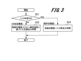
- 4 is a flowchart showing a target ignition timing determination operation in the internal combustion engine control device according to the embodiment.
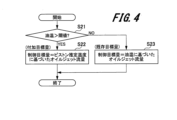
- 4 is a flowchart showing an operation of determining a target oil jet flow rate in the internal combustion engine control device according to the embodiment.
- 2 is a block diagram showing a configuration of a piston temperature/target amount calculation unit in the internal combustion engine control device according to the embodiment
- FIG. 2 is a block diagram showing a configuration of a piston temperature estimation unit in the internal combustion engine control device according to the embodiment;
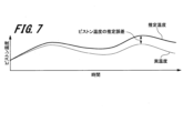
- FIG. 11 is an explanatory diagram showing time histories of an estimated piston temperature and an actual piston temperature when a positive error occurs in the amount of energy transmitted to the piston.
- FIG. 4 is an explanatory diagram showing the relationship between piston temperature and knock intensity. 4 is a flowchart showing an operation of determining a correction timing for an estimated piston temperature in the internal combustion engine control device according to the embodiment;
- FIG. 4 is an explanatory diagram showing the relationship between an oil jet flow rate and a knock intensity.
- FIG. 4 is an explanatory diagram showing the relationship between the oil jet flow rate and the ignition timing.
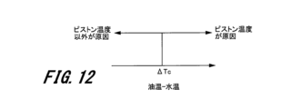
- FIG. 4 is an explanatory diagram showing the relationship between the temperature difference between the oil temperature and the water temperature and the cause of knocking.
- 4 is a flowchart showing an operation of determining a temperature correction command and a temperature correction value in the internal combustion engine control device according to the embodiment.
- 4 is a flowchart showing an operation of calculating an estimated piston temperature in the internal combustion engine control device according to the embodiment.
- 4 is an explanatory diagram showing an example of a time history of knock determination, temperature correction determination, estimated piston temperature, and piston temperature estimation error due to the correction operation of the estimated piston temperature in the internal combustion engine control device according to the embodiment.
- 11 is an explanatory diagram showing an example of changes in piston temperature during knock with respect to changes in the octane number of the fuel, the alcohol concentration in the fuel, the latent heat of vaporization of the fuel, the rotation speed of the internal combustion engine, the humidity of the intake air, and the EGR rate (the mass ratio of recirculated gas to the intake air).
- 1 is an explanatory diagram showing an example of changes in piston temperature during knock with respect to changes in intake air amount, intake air pressure, intake air temperature, air-fuel ratio, compression ratio, and amount of deposits in the combustion chamber.
- FIG. FIG. 4 is an explanatory diagram showing the relationship between the estimated piston temperature and the knock risk degree.
- FIG. 1 is an explanatory diagram showing an example of a method for determining an oil jet flow rate based on a knock risk degree, which is implemented by a target amount calculation unit in an internal combustion engine control device according to an embodiment.
- FIG. 11 is an explanatory diagram showing another example of a method for determining an oil jet flow rate based on a knock risk degree, which is implemented in a target amount calculation unit in an internal combustion engine control device according to an embodiment.
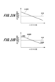
- FIG. 21A and 21B are explanatory diagrams showing an example of a method for determining the ignition advance angular velocity based on the knock risk degree in the internal combustion engine control device according to the embodiment.
- 4 is an explanatory diagram showing an example of time history of knock determination, target ignition timing, piston temperature, and knock risk degree.
- Fig. 1 is a schematic diagram showing the configuration of an internal combustion engine.
- the internal combustion engine 100 shown in FIG. 1 is a spark-ignition type four-stroke gasoline internal combustion engine that repeats four strokes: an intake stroke, a compression stroke, a combustion (expansion) stroke, and an exhaust stroke. Furthermore, the internal combustion engine 100 is a multi-cylinder engine having, for example, four cylinders. Note that the number of cylinders that the internal combustion engine 100 has is not limited to four, and the internal combustion engine 100 may have six or eight or more cylinders. Alternatively, the number of cylinders that the internal combustion engine 100 has may be three or less. Furthermore, the number of cycles of the internal combustion engine 100 is not limited to four cycles.
- the internal combustion engine 100 includes a cylinder head 24, a cylinder block 23, a piston 25, an intake valve 26, and an exhaust valve 27.
- a combustion chamber is formed by the cylinder head 24, the cylinder block 23, the piston 25, the intake valve 26, and the exhaust valve 27.
- An ignition plug and an ignition coil 22 are installed in the cylinder head 24.
- the internal combustion engine 100 also includes an electronically controlled throttle valve 31, an intake port 32, an exhaust port 33, a catalytic converter 34, and a fuel injection device 35.
- the internal combustion engine 100 also includes an air flow sensor 36, an air-fuel ratio sensor 37, a knock sensor 38, an oil temperature sensor 39, an oil pan 40, and a water temperature sensor 41.
- the internal combustion engine 100 is controlled by an ECU (Engine Control Unit) 2.
- Air for combustion is taken into the combustion chamber through an electronically controlled throttle valve 31 and an intake port 32. Then, the post-combustion gas (exhaust gas) discharged from the combustion chamber is discharged into the atmosphere through an exhaust port 33 and a catalytic converter 34. In addition, fuel is supplied into the intake port 32 by a fuel injection device 35.
- the amount of air taken into the combustion chamber is measured by the ECU 2 reading the output of an airflow sensor 36 located upstream of the electronically controlled throttle valve 31.
- a temperature sensor and a humidity sensor are also installed inside the airflow sensor 36.
- the ECU 2 reads the output of the airflow sensor 36 to detect the temperature and humidity of the intake air.
- the air-fuel ratio of the gas (exhaust gas) discharged from the combustion chamber is detected by the ECU 2 reading the output of an air-fuel ratio sensor 37 provided upstream of the catalytic converter 34.
- a knock sensor 38 is provided in the cylinder block 23. The ECU 2 detects the knocking condition in the combustion chamber by reading the output of the knock sensor 38.
- a water jacket 42 is provided inside the cylinder block 23, and the cylinder block 23 is cooled by cooling water flowing through the water jacket 42 by a cooling water pump (not shown). The heat of the cooling water is released into the atmosphere by a radiator (not shown).
- a water temperature sensor 41 is provided in the water jacket 42. The ECU 2 reads the output of the water temperature sensor 41 to detect the temperature of the cooling water (water temperature).
- An oil pan 40 that stores oil is provided under the cylinder block 23.
- An oil temperature sensor 39 is provided in the oil pan 40.
- the ECU 2 reads the output of the oil temperature sensor 39 to detect the oil temperature.
- an oil jet 53 is attached to the cylinder block 23.
- the oil jet 53 has the function of cooling the piston 25 by injecting oil toward the back side of the piston 25.
- the flow rate of oil sprayed by the oil jet 53 (oil jet flow rate) varies depending on the oil discharge pressure of an oil pump (not shown) connected to the oil jet 53.
- the flow rate of oil sprayed by the oil jet 53 varies depending on the opening of a valve mechanism (not shown) built into the oil jet 53.
- the discharge pressure of the oil pump or the opening of the valve mechanism built into the oil jet 53 is changed by the operation signal value sent from the ECU 2.
- the cylinder block 23 is provided with an oil supply passage (main gallery) 56 that supplies oil to the oil supply parts, including the oil jet 53.
- the oil stored in the oil pan 40 provided at the bottom of the cylinder block 23 is pressurized by an oil pump (not shown).
- the oil pressurized by the oil pump is then supplied via the oil supply passage 56 to the oil jet 53 as well as to lubrication parts, hydraulically operated equipment, etc.
- the structure of the oil jet 53 can be, for example, a die-cast type, a brazed two-piece type, or a brazed one-piece type.
- the oil jet 53 is fastened to the cylinder block 23 by a fixing bolt that has a built-in check ball.
- the oil jet 53 is fixed to the cylinder block side by a general fixing bolt that does not have a built-in check ball.
- the check ball supplies oil to the oil jet 53 when the oil pressure in the oil supply passage 56 exceeds the set load of the spring due to the spring.
- the oil jet 53 is configured to spontaneously eject oil when the oil pressure of the oil supplied to the oil supply passage 56 of the internal combustion engine 100 exceeds a predetermined value.
- the valve is a solenoid type, and the opening degree of the valve is adjusted to stop the oil jet or adjust the oil jet flow rate during injection.
- the opening and closing timing of the intake valve 26 and exhaust valve 27 is adjusted by a variable valve timing mechanism (not shown).
- the ECU 2 calculates the required torque based on the output signal of the accelerator opening sensor 62 . That is, the accelerator opening sensor 62 is used as a required torque detection sensor that detects the torque required for the internal combustion engine 100.
- the ECU 2 also calculates the rotation speed of the internal combustion engine 100 based on the output signal of the crank angle sensor 10.
- the ECU 2 then optimally calculates main operating quantities of the internal combustion engine 100, such as the air flow rate, fuel injection amount, ignition timing, fuel pressure, oil pressure, valve timing, etc., based on the operating conditions of the internal combustion engine 100 obtained from the outputs of various sensors.
- the fuel injection amount calculated by the ECU 2 is converted into a valve opening pulse signal and output to the fuel injection device 35.
- the ignition timing calculated by the ECU 2 is output to the ignition coil 22 as an ignition signal.
- the throttle opening calculated by the ECU 2 is output to the electronically controlled throttle valve 31 as a throttle drive signal.
- the internal combustion engine 100 may also be provided with an EGR (Exhaust Gas Recirculation) pipe (not shown) that connects the intake port (intake pipe) 32 and the exhaust port (exhaust pipe) 33.
- This EGR pipe may return a portion of the exhaust gas passing through the exhaust port 33 to the intake port 32.
- the ECU 2 adjusts the flow rate (EGR amount) of exhaust gas returned to the intake port 32 by manipulating the opening of a flow control valve provided in the EGR pipe based on the operating state of the internal combustion engine 100 obtained from the output of various sensors.
- the internal combustion engine 100 may also be provided with a variable compression ratio mechanism (not shown).
- the variable compression ratio mechanism is a mechanism that changes the compression ratio by adjusting the stroke amount of the piston 25.
- the ECU 2 adjusts the compression ratio of the internal combustion engine 100 by operating the variable compression ratio mechanism (not shown) based on the operating state of the internal combustion engine 100 obtained from the output of various sensors.
- Fuel for the internal combustion engine 100 may be liquid fuel such as gasoline, alcohol (ethanol, methanol), or synthetic fuel (eFuel), or gas fuel such as methane, propane, hydrogen, or ammonia, or a mixture of these.
- liquid fuel such as gasoline, alcohol (ethanol, methanol), or synthetic fuel (eFuel)
- gas fuel such as methane, propane, hydrogen, or ammonia, or a mixture of these.
- FIG. 2 is a block diagram showing the configuration of the ECU 2.
- the ECU 2 has an input circuit 3, an input/output port 4, a RAM (Random Access Memory) 5, a ROM (Read Only Memory) 6, and a CPU (Central Processing Unit) 7.
- the ECU 2 also has an oil jet control unit 8, an ignition control unit 9, and a piston temperature/target amount calculation unit 11.
- the input circuit 3 receives sensor output values from various sensors, such as the water temperature from a water temperature sensor 41, the intake air amount from an air flow sensor 36, and the knock intensity from a knock sensor 38.
- the input circuit 3 performs signal processing such as noise removal on the input signal and sends the signal to the input/output port 4.
- the value input to the input port of the input/output port 4 is stored in the RAM 5.
- ROM 6 stores a control program describing the contents of the various calculation processes executed by CPU 7, as well as maps and data tables used for each process.
- RAM 5 has a storage area for storing values input to the input port of input/output port 4 and values representing the amount of operation of each actuator calculated according to the control program. In addition, the values representing the amount of operation of each actuator stored in RAM 5 are sent to the output port of input/output port 4.
- the piston temperature/target quantity calculation unit 11 receives the sensor output values and operation amounts of each actuator and the state quantities of the internal combustion engine from the input/output port 4, and estimates the piston temperature. The piston temperature/target quantity calculation unit 11 then calculates the control target quantities of each actuator based on the estimated piston temperature, and outputs them to the oil jet control unit 8 and the ignition control unit 9.
- the oil jet control unit 8 calculates the existing target oil jet flow rate based on the sensor output values received from the input/output port 4, the operation amounts of each actuator, and the state quantities of the internal combustion engine 100.
- the oil jet control unit 8 also receives the additional target oil jet flow rate from the piston temperature/target amount calculation unit 11.
- the oil jet control unit 8 selects either the existing target oil jet flow rate or the additional target oil jet flow rate as the control target amount for the oil jet, and determines the operation amount for the oil jet 53.
- the ignition control unit 9 determines the existing target ignition timing based on the sensor output values received from the input/output port 4, the operation amounts of each actuator, and the state quantities of the internal combustion engine 100.
- the ignition control unit 9 also receives the additional target ignition timing from the piston temperature/target quantity calculation unit 11.
- the ignition control unit 9 selects either the existing target ignition timing or the additional target ignition timing as the control target quantity for the ignition timing, and determines the operation amount of the ignition coil 22.
- the oil jet control unit 8 and the ignition control unit 9 receive the actuator control target amount (hereinafter referred to as the additional target amount) determined by the piston temperature/target amount calculation unit 11.
- the oil jet control unit 8 and the ignition control unit 9 also obtain the actuator control target amount (hereinafter referred to as the existing target amount) determined based on the sensor output value, the operation amount of each actuator, and the internal combustion engine state amount received from the input/output port 4 without going through the piston temperature/target amount calculation unit 11.
- the oil jet control unit 8 and the ignition control unit 9 select the actuator control target amount optimal for the current internal combustion engine control from the two target amounts, the additional target amount and the existing target amount.
- the oil jet control unit 8 and the ignition control unit 9 also obtain the actuator operation amount for achieving the selected control target amount and output it to the actuator.
- the oil jet control unit 8 and the ignition control unit 9 select the additional target amount and the existing target amount because the optimal target amount may change depending on the internal combustion engine state, etc.
- the additional target amount is determined based on the estimated piston temperature, so there is a possibility of response delays and errors. Therefore, when a knock occurs, it is desirable to control ignition using the ignition timing at the time of knock (existing target amount) determined based on the sensor output value received from the input/output port 4, the operation amount of each actuator, and the internal combustion engine state amount without going through the piston temperature/target amount calculation unit 11, as the target ignition timing.
- FIG. 3 is a flowchart showing the operation of determining the target ignition timing.
- the ignition control unit 9 determines whether the knock judgment is ON or not (step S11). In the process of step S11, if it is determined that the knock judgment is OFF, that is, that knock has not occurred (NO determination in step S11), the ignition control unit 9 selects the target ignition timing (additional target amount) calculated by the piston temperature/target amount calculation unit 11 as the control target amount (step S12).
- step S11 if it is determined that the knock judgment is ON, that is, that a knock has occurred (YES judgment in step S11), the ignition control unit 9 selects the knock ignition timing determined based on the sensor output values received from the input/output port 4, the operation amounts of each actuator, and the internal combustion engine state quantities as the control target quantity (step S13). Specifically, the ignition control unit 9 selects the retarded ignition timing for transitioning the internal combustion engine 100 from a knock state to a non-knock state as the control target quantity (step S13).
- FIG. 4 is a flowchart showing the operation of determining the target oil jet flow rate.
- the oil jet control unit 8 determines whether the oil temperature (or water temperature) is higher than a predetermined threshold (e.g., 20°C) (step S21). In the process of step S21, if the oil temperature is higher than the threshold (YES judgment in step S21), the oil jet control unit 8 selects the target oil jet flow rate (additional target amount) calculated by the piston temperature/target amount calculation unit 11 as the control target amount (step S22).
- a predetermined threshold e.g. 20°C
- step S21 if the oil temperature is equal to or lower than the threshold value (NO judgment in step S21), the oil jet control unit 8 selects the oil jet flow rate (existing target amount) determined based on the oil temperature received from the input/output port 4 as the control target amount (step S23).
- the oil jet control unit 8 and the ignition control unit 9 are used as an example of a control unit that determines the actuator operation amount, but the present invention is not limited to these.
- the control unit that determines the actuator operation amount may be other actuator control units such as a fuel injection control unit (which outputs the operation amount of the fuel injection valve and the fuel pump), a valve timing control unit (which outputs the operation amount of the valve timing mechanism), a variable compression ratio control unit (which outputs the operation amount of the variable compression ratio mechanism), an air volume control unit (which outputs the operation amount of the electronically controlled throttle valve), or a hydraulic control unit (which outputs the operation amount of the oil pump).
- a fuel injection control unit which outputs the operation amount of the fuel injection valve and the fuel pump
- a valve timing control unit which outputs the operation amount of the valve timing mechanism
- a variable compression ratio control unit which outputs the operation amount of the variable compression ratio mechanism
- an air volume control unit which outputs the operation amount of the electronically controlled throttle valve
- a hydraulic control unit which outputs the operation
- FIG. 5 is a block diagram showing the configuration of a piston temperature/target amount calculation unit 11 which is a part of the internal configuration of the ECU 2.
- the piston temperature/target quantity calculation unit 11 includes a piston temperature estimation unit 12, a temperature correction unit 14, a temperature correction determination unit 15, and a target quantity calculation unit 16.
- the piston temperature estimation unit 12 receives the sensor output value, the operation amount of each actuator, and the internal combustion engine state quantity from the input/output port 4.
- the piston temperature estimation unit 12 estimates the piston temperature based on the sensor output value, the operation amount of each actuator, and the internal combustion engine state quantity.
- the piston temperature estimation unit 12 also outputs the estimated piston temperature to the target quantity calculation unit 16 and the temperature correction determination unit 15.
- the temperature correction determination unit 15 receives the sensor output value, the operation amount of each actuator, and the internal combustion engine state quantity from the input/output port 4. The temperature correction determination unit 15 also receives the piston estimated temperature from the piston temperature estimation unit 12. The temperature correction determination unit 15 then determines the timing to correct the piston temperature based on the sensor output value, the operation amount of each actuator, the internal combustion engine state quantity, and the piston estimated temperature. The temperature correction determination unit 15 also outputs the determined temperature correction timing to the temperature correction unit 14.
- the temperature correction unit 14 outputs a correction command and a temperature correction value to the piston temperature estimation unit 12 based on the timing of temperature correction determined by the temperature correction determination unit 15.
- the temperature correction unit 14 also outputs the knock-time piston temperature Tk, which will be described later, to the target amount calculation unit 16.
- the target amount calculation unit 16 then calculates the control target amount for each actuator based on the estimated piston temperature.
- FIG. 6 is a block diagram showing the configuration of the piston temperature estimation unit 12 which is a part of the internal configuration of the piston temperature/target amount calculation unit 11.
- the piston temperature estimation unit 12 includes an energy transmission amount estimation unit 17 and a temperature calculation unit 18.
- the energy transmission amount estimation unit 17 receives the sensor output value, the operation amount of each actuator, and the internal combustion engine state quantity from the input/output port 4.
- the energy transmission amount estimation unit 17 determines the amount of energy transmission to the piston 25 based on the sensor output value, the operation amount of each actuator, and the internal combustion engine state quantity.
- the energy transmission amount estimation unit 17 also outputs the determined amount of energy transmission to the temperature calculation unit 18.
- the temperature calculation unit 18 obtains the piston temperature from the amount of energy transmitted to the piston 25.
- the temperature calculation unit 18 calculates the estimated piston temperature by the following Equation 1 using the amount of energy transmitted to the piston 25 input from the energy transmission amount estimation unit 17. [Formula 1]
- Equation 1 is expressed in the form of a time integral of the amount of energy transmitted to the piston 25, Q(t). Therefore, if the amount of energy transmitted to the piston 25, Q(t), contains an error, there is a risk that the error will accumulate over time.
- FIG. 7 is an explanatory diagram showing time histories of the estimated piston temperature and the actual piston temperature when a positive error occurs in the amount of energy transmitted to the piston. If a positive error occurs in the amount of energy transmitted to the piston 25, Q(t), the estimated piston temperature will be higher than the actual temperature, as shown in Fig. 7.
- a case in which a positive error occurs in the amount of energy transmitted to the piston Q(t) is a case in which the amount of energy transmitted to the piston 25, Q, is overestimated.
- the difference between the estimated piston temperature and the actual temperature increases over time.
- FIG. 8 is a graph showing an example of the relationship between the piston temperature and the knock intensity.
- an increase in the temperature of the piston 25 is the cause of the occurrence of knock, it is known that there is a strong linear correlation between the piston temperature and the knock intensity, as shown in Fig. 8.
- an increase in the temperature of the piston 25 is the cause of the occurrence of knock, it refers to the case where the self-ignition of gas on the piston surface that is heated by heat transfer from the piston is the cause of the occurrence of knock.
- the knock intensity is calculated based on the output of the knock sensor 38, and when the knock intensity exceeds a predetermined knock judgment threshold, it is determined that a knock state has occurred (hereinafter, knock judgment ON). Furthermore, as shown in FIG. 8, since there is a correlation between the piston temperature and the knock intensity, it is considered that the piston temperature when knock judgment ON (i.e., the knock intensity is the knock judgment threshold) is approximately constant.
- the piston temperature when the knock intensity exceeds the knock judgment threshold is referred to as the knock-time piston temperature (predetermined temperature) Tk.
- the piston temperature/target amount calculation unit 11 corrects the estimated piston temperature to the knock piston temperature Tk when a predetermined condition is met. This prevents the accuracy of the piston temperature estimation from decreasing over time.
- FIG. 9 is a flowchart showing the operation of determining the correction timing of the estimated piston temperature.
- the temperature correction determination unit 15 reads the knock state flag calculated by the ECU 2 and determines the current knock occurrence state (step S31). In the process of step S31, if the temperature correction determination unit 15 determines that the knock determination is ON (knock state), it proceeds to the process of step S32, and if it determines that the knock determination is OFF (not a knock state), it proceeds to the process of step S35. In the process of step S35, the temperature correction determination unit 15 sets the temperature correction determination flag to OFF (not the timing for correcting the estimated piston temperature). Then, the temperature correction determination unit 15 sends a message that the temperature correction determination flag is OFF to the temperature correction unit 14, and returns to the process of step S31.
- a predetermined threshold value Tc e.g. 10°C
- step S33 the temperature correction determination unit 15 determines whether or not the knock is caused by the piston temperature. If it is determined in the process of step S33 that the knock is caused by the piston temperature (YES determination in step S33), the process proceeds to step S34. On the other hand, if it is determined in the process of step S33 that the knock is not caused by the piston temperature (NO determination in step S33), the process proceeds to step S35.
- the temperature correction determination unit 15 sets the temperature correction determination flag to ON (this is the timing for correcting the estimated piston temperature). Then, the temperature correction determination unit 15 sends a signal that the temperature correction determination flag is ON to the temperature correction unit 14, and the process returns to the process of step S31.
- the temperature correction determination flag is ON and is sent from the temperature correction determination unit 15 to the temperature correction unit 14. In all other cases, the temperature correction determination flag is OFF and is sent from the temperature correction determination unit 15 to the temperature correction unit 14.
- step S32 the process of determining whether an error of equal to or greater than threshold value Tc occurs in the current estimated piston temperature, which is shown in step S32, may be omitted. That is, regardless of the magnitude of the error in the current estimated piston temperature, when a knock caused by the piston temperature occurs, a temperature correction determination signal "ON" (temperature correction determination flag is "ON") is sent from temperature correction determination unit 15 to temperature correction unit 14. Then, when knock caused by the piston temperature is not occurring, a temperature correction determination OFF (the temperature correction determination flag is OFF) may be sent from temperature correction determination unit 15 to temperature correction unit 14.
- the calculation load on ECU 2 can be reduced.
- Fig. 10 is an explanatory diagram showing the relationship between the oil jet flow rate and the knock intensity.
- Fig. 10 also shows an example of the change in knock intensity when the oil jet flow rate is changed while keeping the ignition timing constant. 10
- knock is caused by the piston temperature
- increasing the oil jet flow rate to improve piston cooling reduces the knock intensity significantly.
- knock is caused by a factor other than the piston temperature (for example, when knock is caused by an increase in the temperature of the cylinder head or cylinder liner)
- increasing the oil jet flow rate to improve piston cooling only changes the knock intensity slightly.
- Fig. 11 is an explanatory diagram showing the relationship between the oil jet flow rate and the ignition timing.
- Fig. 11 also shows the change in ignition timing (change in ignition timing of trace knock) when the oil jet flow rate is changed while keeping the knock intensity constant.
- ignition timing change in ignition timing of trace knock
- the knock is caused by the piston temperature from the magnitude of the change in ignition timing relative to the change in oil jet flow rate. More specifically, if the magnitude of the change in ignition timing relative to the change in oil jet flow rate is equal to or greater than a predetermined threshold (for example, a 0.1° change in ignition timing relative to a 10% change in oil jet flow rate), it is determined that the knock is caused by the piston temperature. And, if the magnitude of the change in ignition timing relative to the change in oil jet flow rate is smaller than a predetermined threshold, it is possible to determine that the knock is caused by a factor other than the piston temperature.
- a predetermined threshold for example, a 0.1° change in ignition timing relative to a 10% change in oil jet flow rate
- FIG. 12 is a graph showing the relationship between the temperature difference between the oil temperature and the water temperature and the cause of knock.
- the piston temperature is highly correlated with the oil temperature
- the cylinder head temperature and cylinder liner temperature which are causes of knock other than the piston temperature
- the water temperature is highly correlated with the water temperature. Therefore, if the temperature difference between the oil temperature and the water temperature (oil temperature - water temperature) is greater than a preset threshold value ⁇ Tc (e.g., 30°C), it is determined that the knock is caused by the piston temperature.
- ⁇ Tc e.g. 30°C
- FIG. 13 is a flowchart showing the operation of determining a temperature correction command and a temperature correction value.
- step S44 the temperature correction unit 14 sends a temperature correction command OFF (do not correct the estimated piston temperature) to the piston temperature estimation unit 12, and the process returns to step S41.
- step S42 the temperature correction unit 14 sets the temperature correction value of the estimated piston temperature to the piston temperature during knock Tk. Then, the temperature correction unit 14 sends a temperature correction command ON (to correct the estimated piston temperature) and a temperature correction value (piston temperature during knock Tk) to the piston temperature estimation unit 12 (step S43), and the process returns to the process of step S41.
- FIG. 14 is a flowchart showing the operation of calculating the estimated piston temperature.
- the piston temperature estimation unit 12 receives a temperature correction command from the temperature correction unit 14. Then, the piston temperature estimation unit 12 judges whether the temperature correction command is ON or not (step S51). In the process of step S51, if the piston temperature estimation unit 12 judges that the temperature correction command is ON (to correct the estimated piston temperature) (YES judgment in step S51), it proceeds to the process for correcting the estimated piston temperature, that is, the process of step S52.
- step S51 if the piston temperature estimation unit 12 determines that the temperature correction command is OFF (the piston estimated temperature is not corrected) (NO determination in step S51), it calculates the piston estimated temperature based on the amount of energy transmitted. In other words, it proceeds to the process of step S53.
- the piston temperature estimation unit 12 replaces the current estimated piston temperature with the temperature correction value received from the temperature correction unit 14 (step S52). Then, the process proceeds to step S55, which will be described later.
- the piston temperature estimation unit 12 calculates the amount of energy transmission to the piston 25 based on the actuator operation amount, the sensor output, and the internal combustion engine state amount (step S53).
- the piston temperature estimation unit 12 calculates the estimated piston temperature by integrating the amount of energy transmission to the piston 25 using the above-mentioned formula 1 (step S54). Then, the process proceeds to step S55.
- step S555 the piston temperature estimation unit 12 sends the calculated or replaced estimated piston temperature to the target amount calculation unit 16, and returns to the processing of step S51.
- FIG. 15 is an explanatory diagram showing an example of a time history of knock determination, temperature correction determination, estimated piston temperature, and piston temperature estimation error due to the correction operation of the estimated piston temperature.
- the estimated piston temperature is corrected to the knock piston temperature Tk. This temperature correction suppresses the accumulation of errors in the piston temperature estimation. As a result, it is possible to prevent the accuracy of the estimated piston temperature from decreasing over time.
- FIG. 16 is an explanatory diagram showing an example of the change in the piston temperature Tk during knock with respect to changes in the octane number of the fuel, the alcohol concentration in the fuel, the latent heat of vaporization of the fuel, the rotational speed of the internal combustion engine, the humidity of the intake air, and the EGR rate (the mass ratio of recirculated gas to the intake air).
- the temperature correction unit 14 sets the temperature correction value to be higher as the octane number of the fuel, the alcohol concentration in the fuel, the latent heat of vaporization of the fuel, the rotation speed of the internal combustion engine, the humidity of the intake air, and the EGR rate are greater.
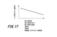
- FIG. 17 is an explanatory diagram showing an example of changes in knock-time piston temperature Tk with respect to changes in intake air amount, intake air pressure, intake air temperature, air-fuel ratio, compression ratio, and amount of deposits in the combustion chamber.
- the disturbances are not limited to the examples shown in Figures 16 and 17 above, but comprehensively include factors that affect the likelihood of knock occurring. For a factor that makes it more difficult for knock to occur the greater the degree of the disturbance, temperature correction unit 14 sets a higher temperature correction value the greater the factor. Also, for a factor that makes it more likely for knock to occur the greater the degree of the disturbance, temperature correction unit 14 sets a lower temperature correction value the greater the factor. By changing the temperature correction value in accordance with the degree of disturbance in this way, the accuracy of the corrected piston estimated temperature is further improved.
- the temperature correction unit 14 or the piston temperature and target amount calculation unit 11 acquires disturbance information from a sensor that detects disturbances. Then, the temperature correction unit 14 or the piston temperature and target amount calculation unit 11 calculates a temperature correction value (piston temperature Tk during knocking) based on the acquired disturbance information using a pre-set map, data table, or formula.
- FIG. 18 is a graph showing the relationship between the estimated piston temperature and the knock risk degree.
- the ECU 2 uses the estimated piston temperature as a means for measuring the risk of knocking.
- the knock risk degree is an amount proportional to the estimated piston temperature.
- the knock risk degree is defined as 1 when the estimated piston temperature is the piston temperature Tk at the time of knocking, and as the estimated piston temperature is 0°C, the knock risk degree is defined as 0.
- the knock risk degree defined in this way is an index indicating that the risk of knocking increases as the degree approaches 1 from 0.
- the target amount calculation unit 16 calculates the knock risk degree from the piston temperature Tk at the time of knocking. The target amount calculation unit 16 then determines the control target value of the oil jet flow rate based on the knock risk degree.
- FIG. 19 is an explanatory diagram showing an example of a method for determining the oil jet flow rate based on the knock risk degree, which is implemented by the target amount calculation unit 16.
- a predetermined first threshold C1 e.g., 0.9
- the target amount calculation unit 16 increases the target oil jet flow rate from G0 to G1.
- a predetermined second threshold C2 e.g., 0.8
- the target amount calculation unit 16 decreases the target oil jet flow rate from G1 to G0.
- the first threshold C1 which is the threshold for an increase
- the second threshold C2 which is the threshold for a decrease
- FIG. 20 is an explanatory diagram showing another example of the method for determining the oil jet flow rate based on the knock risk degree, which is implemented by the target amount calculation unit 16.
- a predetermined threshold C1 e.g., 0.9
- the target amount calculation unit 16 increases the target oil jet flow rate as the knock risk degree increases until the target oil jet flow rate reaches the upper limit value Gmax.
- the oil jet flow rate may be determined directly based on the estimated piston temperature instead of the knock risk degree.
- the target amount calculation unit 16 may increase the target oil jet flow rate from G0 to G1 when the estimated piston temperature exceeds a predetermined first threshold (e.g., 150°C).
- the target amount calculation unit 16 may also decrease the target oil jet flow rate from G1 to G0 when the estimated piston temperature falls below a predetermined second threshold (e.g., 140°C).
- the target amount calculation unit 16 may increase the target oil jet flow rate as the estimated piston temperature increases until the target oil jet flow rate reaches an upper limit value Gmax.
- the knock risk degree is an index normalized by the piston temperature Tk during knock. Therefore, even if the piston temperature Tk during knock changes due to a disturbance, the effect is automatically reflected in the knock risk degree. Therefore, by determining the target oil jet amount using the knock risk degree, it becomes unnecessary to change the threshold values (C1, C2) for determining the change point of the oil jet flow rate even if the piston temperature Tk during knock changes. This has the advantage of simplifying the control software.
- the oil jet flow rate is increased in advance before knocking occurs, promoting cooling of the piston 25. This makes it possible to prevent knocking from occurring, or to reduce the intensity of the knock if it does occur. As a result, it is possible to improve the output of the internal combustion engine 100 and reduce exhaust losses.
- the oil jet flow rate is determined based on the estimated piston temperature or the knock risk level calculated from the estimated piston temperature, the oil jet flow rate will be small when the risk of knocking is low. This makes it possible to reduce friction loss associated with the load on the hydraulic pump and to reduce cooling loss by suppressing cooling of the piston 25.
- the ignition timing is set to be more retarded than the normal ignition timing (Minimum Advance for Best Torque, MBT), a so-called ignition retard control is implemented. Then, after the knock subsides and the knock judgment is turned OFF, ignition timing recovery control is implemented to advance the retarded ignition timing toward MBT.
- MBT Minimum Advance for Best Torque
- the ignition advance angular speed (ignition advance angle per unit time d ⁇ ig/dt) in the ignition timing recovery control is changed according to the magnitude of the knock risk degree, based on the estimated piston temperature.
- 21A and 21B are explanatory diagrams showing an example of a method for determining the ignition advance angular velocity based on the knock risk degree.
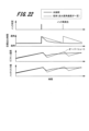
- FIG. 22 is an explanatory diagram showing an example of a time history of knock determination, target ignition timing, piston temperature, and knock risk degree.
- the ignition advance angular velocity when the knock risk is low is set faster than the ignition advance angular velocity when the knock risk is high.
- the knock risk degree is calculated using the estimated piston temperature as shown in FIG. 18.
- an upper or lower limit may be set for the ignition advance rate.
- an upper limit for the ignition advance rate it is possible to reduce the risk of the advance rate becoming too fast and causing knock to reoccur when the knock risk level is low.
- a lower limit for the ignition advance rate it is possible to reduce the risk of the ignition advance rate becoming too slow and causing the ignition timing to be retarded beyond the MBT for a long period of time when the knock risk level is high.
- the ignition advance speed may be determined directly based on the estimated piston temperature instead of the knock risk degree. In other words, the ignition advance speed when the estimated piston temperature is low may be faster than the ignition advance speed when the estimated piston temperature is high.
- the above-mentioned components, functions, processing units, etc. may be realized in part or in whole in hardware, for example by designing an integrated circuit. Further, the above-mentioned components, functions, etc. may be realized in software by a processor interpreting and executing a program that realizes each function. Information on the programs, tables, files, etc. that realize each function can be stored in a recording device such as memory, a hard disk, or an SSD (Solid State Drive), or on a recording medium such as an IC card, an SD card, or a DVD.
- a recording device such as memory, a hard disk, or an SSD (Solid State Drive)
- a recording medium such as an IC card, an SD card, or a DVD.
- 2...ECU internal combustion engine control unit
- 3...input circuit 4...input/output port, 5...RAM, 6...ROM, 7...CPU, 8...oil jet control unit, 9...ignition control unit, 10...crank angle sensor, 11...piston temperature/target amount calculation unit, 12...piston temperature estimation unit, 14...temperature correction unit, 15...temperature correction judgment unit, 16...target amount calculation unit, 17...energy transmission amount estimation unit, 18...temperature calculation unit, 22...ignition coil, 23...cylinder block, 24...serial 25...piston, 26...intake valve, 27...exhaust valve, 31...electronically controlled throttle valve, 32...intake port, 33...exhaust port, 34...catalytic converter, 35...fuel injector, 36...airflow sensor, 37...air-fuel ratio sensor, 38...knock sensor, 39...oil temperature sensor, 40...oil pan, 41...water temperature sensor, 42...water jacket, 53...oil jet, 56...oil supply passage, 62...acceler
Landscapes
- Engineering & Computer Science (AREA)
- Chemical & Material Sciences (AREA)
- Combustion & Propulsion (AREA)
- Mechanical Engineering (AREA)
- General Engineering & Computer Science (AREA)
- Combined Controls Of Internal Combustion Engines (AREA)
Abstract
Priority Applications (2)
| Application Number | Priority Date | Filing Date | Title |
|---|---|---|---|
| DE112024000426.1T DE112024000426T5 (de) | 2023-06-08 | 2024-05-27 | Verbrennungsmotor-Steuervorrichtung und Steuerverfahren für einen Verbrennungsmotor |
| CN202480011795.8A CN120677301A (zh) | 2023-06-08 | 2024-05-27 | 内燃机控制装置及内燃机的控制方法 |
Applications Claiming Priority (2)
| Application Number | Priority Date | Filing Date | Title |
|---|---|---|---|
| JP2023-094946 | 2023-06-08 | ||
| JP2023094946A JP2024176426A (ja) | 2023-06-08 | 2023-06-08 | 内燃機関制御装置及び内燃機関の制御方法 |
Publications (1)
| Publication Number | Publication Date |
|---|---|
| WO2024252969A1 true WO2024252969A1 (fr) | 2024-12-12 |
Family
ID=93795874
Family Applications (1)
| Application Number | Title | Priority Date | Filing Date |
|---|---|---|---|
| PCT/JP2024/019364 Ceased WO2024252969A1 (fr) | 2023-06-08 | 2024-05-27 | Dispositif de commande de moteur à combustion interne et procédé de commande pour moteur à combustion interne |
Country Status (4)
| Country | Link |
|---|---|
| JP (1) | JP2024176426A (fr) |
| CN (1) | CN120677301A (fr) |
| DE (1) | DE112024000426T5 (fr) |
| WO (1) | WO2024252969A1 (fr) |
Citations (3)
| Publication number | Priority date | Publication date | Assignee | Title |
|---|---|---|---|---|
| JP2002147236A (ja) * | 2000-11-16 | 2002-05-22 | Daihatsu Motor Co Ltd | 筒内噴射式内燃機関のピストン頂面温度制御方法 |
| JP2013064374A (ja) * | 2011-09-20 | 2013-04-11 | Nissan Motor Co Ltd | 内燃機関の冷却制御装置 |
| JP2022032184A (ja) * | 2020-08-11 | 2022-02-25 | 日立Astemo株式会社 | 内燃機関制御装置 |
-
2023
- 2023-06-08 JP JP2023094946A patent/JP2024176426A/ja active Pending
-
2024
- 2024-05-27 DE DE112024000426.1T patent/DE112024000426T5/de active Pending
- 2024-05-27 CN CN202480011795.8A patent/CN120677301A/zh active Pending
- 2024-05-27 WO PCT/JP2024/019364 patent/WO2024252969A1/fr not_active Ceased
Patent Citations (3)
| Publication number | Priority date | Publication date | Assignee | Title |
|---|---|---|---|---|
| JP2002147236A (ja) * | 2000-11-16 | 2002-05-22 | Daihatsu Motor Co Ltd | 筒内噴射式内燃機関のピストン頂面温度制御方法 |
| JP2013064374A (ja) * | 2011-09-20 | 2013-04-11 | Nissan Motor Co Ltd | 内燃機関の冷却制御装置 |
| JP2022032184A (ja) * | 2020-08-11 | 2022-02-25 | 日立Astemo株式会社 | 内燃機関制御装置 |
Also Published As
| Publication number | Publication date |
|---|---|
| CN120677301A (zh) | 2025-09-19 |
| DE112024000426T5 (de) | 2025-10-23 |
| JP2024176426A (ja) | 2024-12-19 |
Similar Documents
| Publication | Publication Date | Title |
|---|---|---|
| JP5939263B2 (ja) | 内燃機関の制御装置 | |
| JP5163698B2 (ja) | 内燃機関の点火時期制御装置 | |
| JP4161529B2 (ja) | ディーゼルエンジンの燃料噴射制御装置 | |
| US9382856B2 (en) | System for fuel injection control in an internal combustion engine | |
| CN104583572A (zh) | 内燃机的控制装置 | |
| US9284897B2 (en) | Intake control system for internal combustion engine | |
| US12123366B2 (en) | Internal combustion engine control device | |
| WO2019163459A1 (fr) | Dispositif et procédé de commande de moteur à combustion interne | |
| WO2018179801A1 (fr) | Dispositif de commande pour moteur à combustion interne | |
| JP2011241727A (ja) | 内燃機関の異常検出装置および内燃機関の制御装置 | |
| WO2024252969A1 (fr) | Dispositif de commande de moteur à combustion interne et procédé de commande pour moteur à combustion interne | |
| JP2011140902A (ja) | 内燃機関の制御装置 | |
| JP4830986B2 (ja) | 内燃機関の制御装置 | |
| JP2011157852A (ja) | 内燃機関の制御装置 | |
| JP5925641B2 (ja) | 内燃機関の吸気制御装置 | |
| JP2005273572A (ja) | 内燃機関の燃焼制御装置 | |
| JP6225969B2 (ja) | 過給機付き内燃機関の制御装置及び制御方法 | |
| JP6011461B2 (ja) | 燃焼状態診断装置 | |
| JP2011149313A (ja) | 内燃機関の制御装置 | |
| JP4170773B2 (ja) | 筒内噴射型エンジンの燃料噴射時期制御装置 | |
| JP5076951B2 (ja) | 内燃機関の排気還流装置 | |
| US12410760B2 (en) | Control system for an internal combustion engine, internal combustion engine system, and method for controlling internal combustion engine | |
| JP7261863B2 (ja) | 制御装置、制御方法、及びプログラム | |
| CN113756968B (zh) | 发动机的控制方法和装置 | |
| JP2011247108A (ja) | 内燃機関ノッキング制御装置 |
Legal Events
| Date | Code | Title | Description |
|---|---|---|---|
| 121 | Ep: the epo has been informed by wipo that ep was designated in this application |
Ref document number: 24819201 Country of ref document: EP Kind code of ref document: A1 |
|
| WWE | Wipo information: entry into national phase |
Ref document number: 202480011795.8 Country of ref document: CN |
|
| WWE | Wipo information: entry into national phase |
Ref document number: 112024000426 Country of ref document: DE |
|
| WWP | Wipo information: published in national office |
Ref document number: 202480011795.8 Country of ref document: CN |
|
| WWP | Wipo information: published in national office |
Ref document number: 112024000426 Country of ref document: DE |