WO2024252987A1 - Substrate processing device, method for replacing processing tool, and replacement tool - Google Patents
Substrate processing device, method for replacing processing tool, and replacement tool Download PDFInfo
- Publication number
- WO2024252987A1 WO2024252987A1 PCT/JP2024/019560 JP2024019560W WO2024252987A1 WO 2024252987 A1 WO2024252987 A1 WO 2024252987A1 JP 2024019560 W JP2024019560 W JP 2024019560W WO 2024252987 A1 WO2024252987 A1 WO 2024252987A1
- Authority
- WO
- WIPO (PCT)
- Prior art keywords
- tool
- holding
- replacement
- replacement tool
- processing tool
- Prior art date
- Legal status (The legal status is an assumption and is not a legal conclusion. Google has not performed a legal analysis and makes no representation as to the accuracy of the status listed.)
- Ceased
Links
Images


Classifications
-
- H—ELECTRICITY
- H10—SEMICONDUCTOR DEVICES; ELECTRIC SOLID-STATE DEVICES NOT OTHERWISE PROVIDED FOR
- H10P—GENERIC PROCESSES OR APPARATUS FOR THE MANUFACTURE OR TREATMENT OF DEVICES COVERED BY CLASS H10
- H10P72/00—Handling or holding of wafers, substrates or devices during manufacture or treatment thereof
- H10P72/04—Apparatus for manufacture or treatment
- H10P72/0402—Apparatus for fluid treatment
- H10P72/0406—Apparatus for fluid treatment for cleaning followed by drying, rinsing, stripping, blasting or the like
- H10P72/0411—Apparatus for fluid treatment for cleaning followed by drying, rinsing, stripping, blasting or the like for wet cleaning or washing
- H10P72/0414—Apparatus for fluid treatment for cleaning followed by drying, rinsing, stripping, blasting or the like for wet cleaning or washing using mainly spraying means, e.g. nozzles
-
- B—PERFORMING OPERATIONS; TRANSPORTING
- B05—SPRAYING OR ATOMISING IN GENERAL; APPLYING FLUENT MATERIALS TO SURFACES, IN GENERAL
- B05C—APPARATUS FOR APPLYING FLUENT MATERIALS TO SURFACES, IN GENERAL
- B05C11/00—Component parts, details or accessories not specifically provided for in groups B05C1/00 - B05C9/00
- B05C11/02—Apparatus for spreading or distributing liquids or other fluent materials already applied to a surface ; Controlling means therefor; Control of the thickness of a coating by spreading or distributing liquids or other fluent materials already applied to the coated surface
- B05C11/08—Spreading liquid or other fluent material by manipulating the work, e.g. tilting
-
- B—PERFORMING OPERATIONS; TRANSPORTING
- B05—SPRAYING OR ATOMISING IN GENERAL; APPLYING FLUENT MATERIALS TO SURFACES, IN GENERAL
- B05C—APPARATUS FOR APPLYING FLUENT MATERIALS TO SURFACES, IN GENERAL
- B05C5/00—Apparatus in which liquid or other fluent material is projected, poured or allowed to flow on to the surface of the work
- B05C5/02—Apparatus in which liquid or other fluent material is projected, poured or allowed to flow on to the surface of the work the liquid or other fluent material being discharged through an outlet orifice by pressure, e.g. from an outlet device in contact or almost in contact, with the work
- B05C5/027—Coating heads with several outlets, e.g. aligned transversally to the moving direction of a web to be coated
-
- F—MECHANICAL ENGINEERING; LIGHTING; HEATING; WEAPONS; BLASTING
- F16—ENGINEERING ELEMENTS AND UNITS; GENERAL MEASURES FOR PRODUCING AND MAINTAINING EFFECTIVE FUNCTIONING OF MACHINES OR INSTALLATIONS; THERMAL INSULATION IN GENERAL
- F16L—PIPES; JOINTS OR FITTINGS FOR PIPES; SUPPORTS FOR PIPES, CABLES OR PROTECTIVE TUBING; MEANS FOR THERMAL INSULATION IN GENERAL
- F16L37/00—Couplings of the quick-acting type
- F16L37/24—Couplings of the quick-acting type in which the connection is made by inserting one member axially into the other and rotating it to a limited extent, e.g. with bayonet-action
-
- H—ELECTRICITY
- H10—SEMICONDUCTOR DEVICES; ELECTRIC SOLID-STATE DEVICES NOT OTHERWISE PROVIDED FOR
- H10P—GENERIC PROCESSES OR APPARATUS FOR THE MANUFACTURE OR TREATMENT OF DEVICES COVERED BY CLASS H10
- H10P52/00—Grinding, lapping or polishing of wafers, substrates or parts of devices
-
- H—ELECTRICITY
- H10—SEMICONDUCTOR DEVICES; ELECTRIC SOLID-STATE DEVICES NOT OTHERWISE PROVIDED FOR
- H10P—GENERIC PROCESSES OR APPARATUS FOR THE MANUFACTURE OR TREATMENT OF DEVICES COVERED BY CLASS H10
- H10P72/00—Handling or holding of wafers, substrates or devices during manufacture or treatment thereof
- H10P72/04—Apparatus for manufacture or treatment
- H10P72/0402—Apparatus for fluid treatment
- H10P72/0406—Apparatus for fluid treatment for cleaning followed by drying, rinsing, stripping, blasting or the like
- H10P72/0411—Apparatus for fluid treatment for cleaning followed by drying, rinsing, stripping, blasting or the like for wet cleaning or washing
- H10P72/0412—Apparatus for fluid treatment for cleaning followed by drying, rinsing, stripping, blasting or the like for wet cleaning or washing using mainly scrubbing means, e.g. brushes
-
- H—ELECTRICITY
- H10—SEMICONDUCTOR DEVICES; ELECTRIC SOLID-STATE DEVICES NOT OTHERWISE PROVIDED FOR
- H10P—GENERIC PROCESSES OR APPARATUS FOR THE MANUFACTURE OR TREATMENT OF DEVICES COVERED BY CLASS H10
- H10P72/00—Handling or holding of wafers, substrates or devices during manufacture or treatment thereof
- H10P72/06—Apparatus for monitoring, sorting, marking, testing or measuring
- H10P72/0604—Process monitoring, e.g. flow or thickness monitoring
-
- H—ELECTRICITY
- H10—SEMICONDUCTOR DEVICES; ELECTRIC SOLID-STATE DEVICES NOT OTHERWISE PROVIDED FOR
- H10P—GENERIC PROCESSES OR APPARATUS FOR THE MANUFACTURE OR TREATMENT OF DEVICES COVERED BY CLASS H10
- H10P72/00—Handling or holding of wafers, substrates or devices during manufacture or treatment thereof
- H10P72/30—Handling or holding of wafers, substrates or devices during manufacture or treatment thereof for conveying, e.g. between different workstations
- H10P72/33—Handling or holding of wafers, substrates or devices during manufacture or treatment thereof for conveying, e.g. between different workstations into and out of processing chamber
- H10P72/3302—Mechanical parts of transfer devices
-
- H—ELECTRICITY
- H10—SEMICONDUCTOR DEVICES; ELECTRIC SOLID-STATE DEVICES NOT OTHERWISE PROVIDED FOR
- H10P—GENERIC PROCESSES OR APPARATUS FOR THE MANUFACTURE OR TREATMENT OF DEVICES COVERED BY CLASS H10
- H10P72/00—Handling or holding of wafers, substrates or devices during manufacture or treatment thereof
- H10P72/70—Handling or holding of wafers, substrates or devices during manufacture or treatment thereof for supporting or gripping
- H10P72/76—Handling or holding of wafers, substrates or devices during manufacture or treatment thereof for supporting or gripping using mechanical means, e.g. clamps or pinches
- H10P72/7604—Handling or holding of wafers, substrates or devices during manufacture or treatment thereof for supporting or gripping using mechanical means, e.g. clamps or pinches the wafers being placed on a susceptor, stage or support
- H10P72/7614—Handling or holding of wafers, substrates or devices during manufacture or treatment thereof for supporting or gripping using mechanical means, e.g. clamps or pinches the wafers being placed on a susceptor, stage or support characterised by a plurality of individual support members, e.g. support posts or protrusions
-
- H—ELECTRICITY
- H10—SEMICONDUCTOR DEVICES; ELECTRIC SOLID-STATE DEVICES NOT OTHERWISE PROVIDED FOR
- H10P—GENERIC PROCESSES OR APPARATUS FOR THE MANUFACTURE OR TREATMENT OF DEVICES COVERED BY CLASS H10
- H10P72/00—Handling or holding of wafers, substrates or devices during manufacture or treatment thereof
- H10P72/70—Handling or holding of wafers, substrates or devices during manufacture or treatment thereof for supporting or gripping
- H10P72/78—Handling or holding of wafers, substrates or devices during manufacture or treatment thereof for supporting or gripping using vacuum or suction, e.g. Bernoulli chucks
Definitions
- the present disclosure relates to a substrate processing apparatus, a method for replacing a processing tool used in substrate processing, and a replacement tool for replacing a processing tool used in substrate processing.
- Patent Document 1 discloses a substrate processing apparatus including a holder configured to rotatably hold a substrate, and a supply unit configured to supply a processing liquid through a nozzle to a surface of the substrate held by the holder. It shows.
- This disclosure describes a substrate processing apparatus that allows efficient replacement of processing tools with a simple configuration, a method for replacing processing tools, and a replacement tool.
- An example of a substrate processing apparatus includes a holding section configured to hold a substrate, a rotating section configured to rotate the holding section, a processing tool configured to process the surface of the substrate held in the holding section, an exchange tool configured to be detachably attached to the holding section, a holding and transporting section configured to hold and transport the processing tool, and a control section.
- the exchange tool includes a main body configured to be engageable with an engagement section of the processing tool, and a flange section protruding from the circumferential surface of the main body section for attachment and detachment between the exchange tool and the holding section.
- the processing tool includes another fastening section configured to be fastened to a fastening section provided on the holding and transporting section.
- the control section is configured to execute a first process of attaching and detaching the processing tool to and from the holding and transporting section by controlling the rotating section to rotate the holding section when the replacement tool is attached to the holding section via the flange section and the engagement section of the processing tool is engaged with the main body section of the replacement tool.
- attaching and detaching means at least one of attaching and removing.
- the substrate processing apparatus disclosed herein allows for efficient replacement of processing tools with a simple configuration.
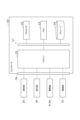
- FIG. 1 is a top view that illustrates a schematic diagram of an example of a substrate processing system.
- FIG. 2 is a side view that illustrates a schematic diagram of an example of a substrate processing system.
- FIG. 3 is a side view that illustrates an example of a thin film processing apparatus.
- FIG. 4 is a top view that illustrates an example of a holding portion.
- FIG. 5 is a cross-sectional view that illustrates an example of a processing tool unit.
- FIG. 6 is a perspective view that illustrates an example of a processing tool.
- FIG. 7 is a perspective view that illustrates an example of a holder and a replacement tool.
- FIG. 8 is a cross-sectional view that illustrates an example of a holder and a replacement tool.
- FIG. 1 is a top view that illustrates a schematic diagram of an example of a substrate processing system.
- FIG. 2 is a side view that illustrates a schematic diagram of an example of a substrate processing system.
- FIG. 9 is a perspective view, partially cut away, showing an example of a holder.
- FIG. 10 is a block diagram showing an example of a main part of a substrate processing system.
- FIG. 11 is a schematic diagram illustrating an example of a hardware configuration of the controller.
- FIG. 12 is a diagram for explaining a procedure for removing the processing tool from the processing tool unit by using the replacement tool.
- FIG. 13 is a diagram for explaining a procedure for removing the processing tool from the processing tool unit by using the replacement tool.
- FIG. 14 is a diagram for explaining a procedure for removing the processing tool from the processing tool unit by using the replacement tool.
- FIG. 15 is a diagram for explaining a procedure for attaching a processing tool to a processing tool unit using an exchange tool.
- FIG. 16 is a diagram for explaining a procedure for attaching the processing tool to the processing tool unit using the replacement tool.
- FIG. 17 is a cross-sectional view that illustrates a schematic diagram of another example of the processing tool.
- FIG. 18( a ) is a cross-sectional view that shows a schematic diagram of another example of the processing tool, and
- FIG. 18( b ) is a cross-sectional view that shows a schematic diagram of another example of the processing tool.
- FIG. 19 is a perspective view that illustrates a schematic diagram of another example of the replacement tool.
- FIG. 20 is a perspective view that illustrates another example of the holding portion.
- 21(a) is a side view showing, in a schematic manner, the state in which the gripping piece of the holding portion of FIG.
- FIG. 20 is releasing the replacement tool of FIG. 19, and FIG. 21(b) is a side view showing, in a schematic manner, the state in which the gripping piece of the holding portion of FIG. 20 is gripping the replacement tool of FIG. 19.
- FIG. 22 is a perspective view that illustrates a schematic diagram of another example of the replacement tool.
- 23 is a top view showing the main body of the replacement tool of FIG. 22.
- FIG. FIG. 24 is a diagram for explaining a state in which a processing tool is attached to the replacement tool of FIG. 23.
- FIG. 25 is a top view that illustrates a schematic diagram of another example of the replacement tool.
- FIG. 26 is a schematic cross-sectional view of the holder and the replacement tool of FIG.
- the substrate processing system 1 may be configured to perform, for example, a photolithography process on the substrate W.
- the photolithography process may include, for example, a process of forming a photosensitive thin film (e.g., a resist film, etc.) on the surface of the substrate W, a process of developing the photosensitive thin film after exposure, etc.
- the substrate W may be disk-shaped or may be a plate-shaped other than circular, such as a polygon.
- the substrate W may have a cutout portion cut out of a portion.
- the cutout portion may be, for example, a notch (a U-shaped, V-shaped, or other groove) or a linear portion extending in a straight line (so-called orientation flat).
- the substrate W may be, for example, a semiconductor substrate (silicon wafer), a glass substrate, a mask substrate, an FPD (Flat Panel Display) substrate, or any other type of substrate.
- the diameter of the substrate W may be, for example, about 200 mm to 450 mm.
- the substrate processing system 1 includes a loading/unloading station 2, at least one processing station 3, an interface station 4, and a controller Ctr (controller).
- the loading/unloading station 2, the at least one processing station 3, and the interface station 4 may be arranged in a line in this order, for example, along the Y direction.
- the at least one processing station 3 may include two or more processing stations 3 arranged between the loading/unloading station 2 and the interface station 4.
- the loading/unloading station 2 includes multiple mounting tables 2a and substrate transport devices 2b, 2c.
- the multiple mounting tables 2a may be lined up, for example, along the X direction (the width direction of the substrate processing system 1).
- Each of the multiple mounting tables 2a is configured to be able to mount one carrier 5 thereon.
- the carrier 5 is configured to accommodate at least one substrate W in a sealed state.
- the substrate transport devices 2b and 2c are each configured to be movable in, for example, the X direction (horizontal direction), the Y direction (horizontal direction), the Z direction (vertical direction), and around the vertical axis ( ⁇ direction).
- the substrate transport devices 2b and 2c may each include a drive mechanism for movement in each of the directions.
- the substrate transport devices 2b and 2c are configured to transfer the substrate W between the carrier 5 and the processing station 3.
- the transfer of the substrate W to the processing station 3 by the substrate transport devices 2b and 2c may include the transfer of the substrate W to the block G3.
- the block G3 may be arranged in the loading/unloading station 2 so as to be located near the substrate transport space 3b (described later) in the processing station 3.
- the block G3 may include multiple transfer devices (not shown) arranged in the vertical direction. Each transfer device may be configured to be accessible to the substrate transport devices 2b and 2c and the substrate transport device 3c (described later) of the processing station 3. Block G3 may be located in processing station 3 instead of in loading/unloading station 2.
- the processing station 3 is configured to perform various photolithography processes on the substrate W.
- the processing station 3 may include a plurality of modules 3a stacked vertically.
- each module 3a may include, for example, blocks G1 and G2 and a substrate transport space 3b extending along the Y direction.
- Blocks G1 and G2 may be lined up in the X direction so as to face each other with the substrate transport space 3b between them.
- Block G1 includes at least one thin film processing apparatus U1.
- Thin film processing apparatus U1 may be an apparatus that performs film processing by supplying a processing liquid to a substrate W, or an apparatus that performs film processing by supplying a predetermined gas to a substrate W.
- Thin film processing apparatus U1 may include, for example, a thin film forming apparatus, a developing processing apparatus, etc.
- Thin film forming apparatus may include, for example, a photosensitive thin film forming apparatus, an anti-reflective film forming apparatus, etc.
- Thin film processing may include forming a thin film and performing a developing process.
- multiple thin film processing apparatuses U1 are arranged in a line along the Y direction, but the number, arrangement, and type of thin film processing apparatuses U1 may be selected arbitrarily.
- the block G2 includes a plurality of heat treatment devices U2, a hydrophobization treatment device (not shown), and a peripheral exposure device U3.
- the plurality of heat treatment devices U2 are configured to perform heat treatment (e.g., heating, cooling) of the substrate W.
- the plurality of heat treatment devices U2 may be arranged vertically and horizontally in the block G2.
- the hydrophobization treatment device is configured to hydrophobize the surface of the substrate W in order to increase the adhesion between the substrate W and the treatment liquid that becomes the photosensitive thin film.
- the peripheral exposure device U3 is configured to expose a portion of the photosensitive thin film formed on the surface of the substrate W that is located at the peripheral portion.
- the hydrophobization treatment device and the peripheral exposure device U3 may be arranged vertically and horizontally in the block G2.
- the number and arrangement of the heat treatment devices U2, the hydrophobization treatment device, and the peripheral exposure device U3 may be selected arbitrarily.
- the peripheral exposure device U3 may be arranged in the interface station 4 instead of the treatment station 3 (block G2) or in addition to the treatment station 3 (block G2).
- a substrate transport device 3c is disposed within the substrate transport space 3b.
- the substrate transport device 3c is configured to be movable, for example, in each of the Y direction (horizontal direction), Z direction (up and down direction), and around the vertical axis ( ⁇ direction).
- the substrate transport device 3c may include a drive mechanism for movement in each of these directions.
- the substrate transport device 3c is configured to move within the substrate transport space 3b and to transfer substrates W between blocks G1 to G5.
- block G4 is disposed in the substrate transport space 3b at the boundary between the two processing stations 3.
- Block G4 may include multiple transfer devices (not shown) arranged vertically. Each transfer device may be configured to be accessible by the substrate transport device 3c of one of the two processing stations 3 and the substrate transport device 3c of the other of the two processing stations 3.
- block G5 may be disposed in interface station 4 so as to be located near substrate transport space 3b in processing station 3.
- Block G5 may include multiple transfer devices (not shown) arranged vertically. Each transfer device may be configured to be accessible by substrate transport device 3c and substrate transport devices 4a and 4b (described later) of interface station 4.
- the interface station 4 connects the processing station 3 to an exposure device (not shown) so as to transfer the substrate W between them.
- the exposure device may be adjacent to the interface station 4, for example, located on the opposite side of the interface station 4 from the processing station 3.
- the interface station 4 includes substrate transport devices 4a and 4b.
- the substrate transport devices 4a and 4b are each configured to be movable in, for example, the X direction (horizontal direction), the Y direction (horizontal direction), the Z direction (up and down direction), and around the vertical axis ( ⁇ direction).
- the substrate transport devices 4a and 4b may each include a drive mechanism for movement in each of the directions.
- the substrate transport devices 4a and 4b are configured to transfer substrates W between the processing station 3, the interface station 4, and the exposure device.
- the transfer of substrates W to and from the processing station 3 by the substrate transport devices 4a and 4b may include the transfer of substrates W to and from the block G5.
- the block G5 may be disposed in the interface station 4 so as to be located near the substrate transfer space 3b in the processing station 3.
- the block G5 may include a plurality of transfer devices (not shown) arranged in the vertical direction. Each transfer device may be configured to be accessible by the substrate transport devices 4a and 4b and the substrate transport device 3c of the processing station 3.
- Block G5 may be located in processing station 3 instead of in interface station 4.
- the controller Ctr is configured to partially or entirely control the substrate processing system 1.
- the thin film processing apparatus U1 includes a chamber 10, a holding unit 20, a suction unit 30, a rotation unit 40, a supply unit 50, a cup member 60, an imaging unit 70, and a cleaning cup 80.
- the chamber 10 is a housing configured so that the substrate W can be loaded and unloaded into and from the chamber.
- An unloading/unloading opening (not shown) is formed in the side wall of the chamber 10. The substrate W is transported into the chamber 10 and unloaded from the chamber 10 to the outside through the unloading/unloading opening by the substrate transport device 3c.
- the holding unit 20 is configured to operate based on a control signal from the controller Ctr and to hold the substrate W.
- the holding unit 20 includes a circular upper surface 21 that extends substantially horizontally, a suction hole 22, and a number of protrusions 23-27.
- the suction hole 22 is provided in the upper surface 21 so as to substantially coincide with the central axis Ax1, which is the center of rotation of the holding unit 20. Therefore, the suction hole 22 includes an opening formed in the upper surface 21 that is open toward the top.
- the multiple protrusions 23-27 are provided on the upper surface 21 so as to protrude upward from the upper surface 21.
- the multiple protrusions 23-27 are configured to support at their tips the substrate W placed on the holder 20.
- Each of the multiple protrusions 23 has an arc shape (e.g., a circular arc shape).
- the multiple protrusions 23 are arranged near the suction hole 22 so as to surround the suction hole 22 and present an annular shape as a whole. Therefore, the ends of adjacent protrusions 23 are spaced apart.
- Each of the multiple protrusions 24 has an arc shape (e.g., a circular arc shape).
- the multiple protrusions 24 are arranged outside the protrusions 23 so as to surround the protrusions 23 and present an annular shape as a whole. Therefore, the ends of adjacent protrusions 24 are spaced apart.
- Each of the multiple protrusions 25 has an arc shape (e.g., a circular arc shape).
- the multiple protrusions 25 are arranged outside the protrusions 24 so as to surround the protrusions 24 and to form a ring shape as a whole. Therefore, the ends of adjacent protrusions 25 are spaced apart.
- Each of the multiple protrusions 26 has an arc shape (e.g., a circular arc shape).
- the multiple protrusions 26 are arranged outside the protrusions 25 so as to surround the protrusions 25 and to form a ring shape as a whole. Therefore, the ends of adjacent protrusions 26 are spaced apart.
- the ridge 27 (first ridge) has an annular (e.g., circular) shape.
- the ridge 27 is arranged outside the ridge 26 so as to surround the ridge 26.
- the ridge 27 may be arranged along the vicinity of the outer periphery of the upper surface 21. Therefore, in the radial direction of the central axis Ax1, the multiple ridges 23 to 26 are arranged on the upper surface 21 inside the ridge 27.
- the suction unit 30 is connected to the suction hole 22.
- the suction unit 30 operates based on a control signal from the controller Ctr, and is configured to suck in the atmosphere near the suction hole 22 through the suction hole 22. Therefore, when the suction unit 30 operates while the substrate W is supported by the multiple protrusions 23-27, the atmosphere in the space between the substrate W and the upper surface 21 of the holder 20 is sucked in through the suction hole 22, and the space becomes negative pressure. As a result, the substrate W is attracted to the holder 20 with its posture approximately horizontal. In other words, the holder 20 and the suction unit 30 constitute a so-called vacuum chuck.
- the rotating unit 40 includes a driving unit 41 and a shaft 42.
- the driving unit 41 is configured to operate based on an operation signal from the controller Ctr and rotate the shaft 42.
- the driving unit 41 may be a power source such as an electric motor.
- the shaft 42 connects the driving unit 41 and the holding unit 20 and extends along the vertical direction. Therefore, the substrate W held by the holding unit 20 rotates around the vertical central axis Ax1 in a substantially horizontal position.
- the holding unit 20 and the rotating unit 40 constitute a so-called spin chuck.
- the supply unit 50 is configured to supply different types of processing liquids from a nozzle 100 (processing tool) to the front surface Wa of the substrate W held in the holding unit 20.
- the supply unit 50 includes a liquid source 51, a pipe 52, a holding base 53 (holding and transporting unit), a drive unit 54 (holding and transporting unit), and at least one nozzle N.
- the liquid source 51 may be configured as a supply source of a processing liquid.
- the processing liquid may be, for example, an acid-based processing liquid or an alkaline processing liquid.
- the pipe 52 connects the liquid source 51 to at least one nozzle 100.
- the pipe 52 is provided with a valve (not shown). The valve is configured to open and close based on an operation signal from the controller Ctr.
- the holding base 53 is configured to hold at least one nozzle 100.
- the holding base 53 includes at least one recess 53a, as illustrated in FIG. 5.
- the holding base 53 may include a number of recesses 53a corresponding to the number of nozzles 100.
- the recess 53a includes a bottom surface 53b and a main portion 53c.
- the bottom surface 53b is provided with a flow path 53e that is connected to the piping 52.
- the main portion 53c accommodates the base end portion 101 (described later) of the nozzle 100.
- the inner circumferential surface of the main portion 53c may be, for example, a substantially cylindrical surface.
- a female thread 53f (fastening portion) is provided on the inner circumferential surface of the main portion 53c.
- the drive unit 54 is connected to the holding base 53.
- the drive unit 54 operates based on an operation signal from the controller Ctr, and is configured to move the holding base 53 horizontally or up and down. Therefore, at least one nozzle N is configured to move horizontally or up and down above the holding unit 20.
- the holding base 53 and the drive unit 54 constitute a holding and transport unit for holding and transporting at least one nozzle 100.
- At least one nozzle 100 is configured to supply processing liquid from the liquid source 51 to the surface Wa of the substrate W when the nozzle 100 is positioned above the substrate W held by the holder 20. To this end, a flow path 100a is provided inside the nozzle 100, extending along the extension direction of the nozzle 100. At least one nozzle 100 may include two or more nozzles 100.
- the nozzle 100 includes a base end 101, a tip end 102, and an irregularly shaped portion 103 (engagement portion).
- the base end 101 has an outer shape that corresponds to the inner peripheral surface of the main portion 53c.
- a male thread 101a (another fastening portion) is provided on the outer peripheral surface of the base end 101.
- the nozzle 100 is attached to the holding base 53 by fastening the male thread 101a to the female thread 53f.
- the nozzle 100 is removed from the holding base 53 by loosening the male thread 101a from the female thread 53f.
- the nozzle 100 includes a male thread 101a that is configured to be fastened to the female thread 53f provided on the main portion 53c of the holding base 53.
- the tip portion 102 has a tapered shape that reduces in diameter toward the tip.
- the irregularly shaped portion 103 is located between the base end portion 101 and the tip portion 102.
- the outer peripheral surface of the irregularly shaped portion 103 has a non-circular irregular shape (a shape other than a perfect circle).
- the overall outer diameter of the irregularly shaped portion 103 may be larger than the inner diameter of the main portion 53c.
- the outer peripheral surface of the irregularly shaped portion 103 may have a generally hexagonal shape as a whole.
- the outer peripheral surface of the irregularly shaped portion 103 may have a shape in which the center of each side of the approximately hexagon is recessed inward in an arc shape.
- the outer diameter of the irregularly shaped portion 103 may be larger than the outer shape of the base end 101 (male thread 101a). Therefore, the upper end of the irregularly shaped portion 103 includes a shoulder 103a that protrudes radially outward from the base end 101.
- the upper surface of the shoulder 103a abuts against the lower surface of the holding base 53, and the end face of the base end 101 abuts against the bottom surface of the recess 53a. This prevents leakage of the processing liquid from the gap between the recess 53a and the nozzle 100.
- the base end 101 may be configured to be elastically deformable.
- the cup member 60 is provided so as to surround the periphery of the holding unit 20.
- the cup member 60 is configured to collect the processing liquid that splashes around from the outer periphery of the substrate W as the substrate W is held and rotated by the holding unit 20 and the rotating unit 40.
- a drainage port 61 and an exhaust port 62 are provided at the bottom of the cup member 60.
- the drain port 61 is configured to discharge the processing liquid collected by the cup member 60 to the outside of the thin film processing apparatus U1.
- the exhaust port 62 is configured to discharge the downward flow formed around the substrate W by the blower (not shown) to the outside of the thin film processing apparatus U1. The downward flow is accompanied by gas generated around the substrate W as the substrate W is processed with the processing liquid.
- the imaging unit 70 is disposed above the holding unit 20.
- the imaging unit 70 is configured to operate based on a control signal from the controller Ctr and capture an image of the center of rotation of the holding unit 20 and its surroundings.
- the imaging unit 70 is configured to transmit the captured image to the controller Ctr.
- the imaging unit 70 may be, for example, a CCD camera, a CMOS camera, etc.
- the installation location of the imaging unit 70 is not particularly limited as long as it can capture an image of the center of rotation of the holding unit 20 and its surroundings.
- the cleaning cup 80 is configured to clean the tip 102 of the nozzle 100 with cleaning liquid after the processing liquid has been supplied to the surface Wa of the substrate W.
- the cleaning cup 80 is positioned outside the cup member 60 and away from the cup member 60.
- the cleaning cup 80 has a bottomed cylindrical shape that opens upward so that the cleaning liquid can be stored.
- the cleaning liquid stored in the cleaning cup 80 may be, for example, a solvent.
- the replacement tool 200 includes a main body portion 210, a flange portion 220, and an annular elastic member 230 (e.g., an O-ring).
- annular elastic member 230 e.g., an O-ring
- the main body 210 has a cylindrical shape as a whole and extends in one predetermined direction.
- the main body 210 includes a base 211 (transmission part), an outer tube 212 (transmission part), a slide part 213, a biasing part 214, and at least one protrusion 215 (transmission part).
- the base portion 211 has a bottomed cylindrical shape and is configured to accommodate the tip portion 102 of the nozzle 100 when the nozzle 100 is attached to the replacement tool 200.
- the base portion 211 includes an upper portion 211a and a lower portion 211b, as illustrated in Figures 8 and 9.
- the outer peripheral surface of the upper portion 211a has an irregular shape that is non-circular (a shape other than a perfect circle).
- the outer peripheral surface of the upper portion 211a may have, for example, a generally hexagonal shape overall.
- the peripheral wall of the upper portion 211a may be provided with a number of accommodating portions 211c (transmission portions) corresponding to the number of at least one protrusion portion 215.
- the accommodating portions 211c may be through holes that penetrate the peripheral wall of the upper portion 211a, or may be grooves that are recessed inward from the outer peripheral surface of the upper portion 211a.
- the accommodating portions 211c may extend in the extension direction of the main body portion 210.
- a cylindrical portion 211d is provided near the inner peripheral edge of the upper end of the upper portion 211a.
- the cylindrical portion 211d extends upward along the extension direction of the exchange tool 200.
- the lower part 211b extends downward from the lower end of the upper part 211a.
- the lower part 211b is inserted into the suction hole 22 of the holding part 20.
- the central axis Ax1 of the holding part 20 and the central axis Ax2 of the replacement tool 200 approximately coincide with each other. Therefore, when the holding part 20 and the replacement tool 200 rotate, the holding part 20 and the replacement tool 200 rotate around approximately the common central axis Ax1, Ax2.
- the lower portion 211b may be integral with the upper portion 211a.
- a cutout 211e may be partially provided on the outer peripheral surface of the lower portion 211b. Therefore, as illustrated in FIG. 8, when the replacement tool 200 is held by the holder 20, a space V1 is formed between the outer peripheral surface of the cutout 211e and the inner peripheral surface of the suction hole 22.
- the cutout 211e may be, for example, a groove (a U-shaped, V-shaped, etc. groove) extending in the extension direction of the main body 210.
- the cutout 211e may be, for example, a flat portion (a so-called D-cut) extending in the extension direction of the main body 210.
- the outer tube portion 212 is disposed outside the base portion 211 and is configured to be slidable relative to the base portion 211.
- the outer tube portion 212 includes a lower portion 212a and an upper portion 212b.
- the inner circumferential surface of the lower portion 212a has a shape corresponding to the outer circumferential surface of the upper portion 211a of the base portion 211. That is, the inner circumferential surface of the lower portion 212a has an irregular shape that is non-circular (a shape other than a perfect circle).
- the inner circumferential surface of the lower portion 212a may have, for example, an approximately hexagonal shape overall.
- the inner shape of the lower portion 212a may be configured to be slightly larger than the outer shape of the upper portion 211a. Therefore, when the upper portion 211a is inserted into the lower portion 212a, the lower portion 212a and the upper portion 211a fit together.
- the outer tube portion 212 rotates together with the base portion 211 without spinning freely. That is, the inner circumferential surface of the lower portion 212a and the outer circumferential surface of the upper portion 211a form a transmission portion that transmits rotational force between the base portion 211 and the outer tube portion 212.
- the peripheral wall of the lower portion 212a may have at least one through hole 212c in a number corresponding to the number of protrusions 215.
- a female screw may be formed on the inner peripheral surface of the through hole 212c.
- the inner circumferential surface of the upper portion 212b (the inner circumferential surface of the opening OP of the main body portion 210) has a shape corresponding to the outer circumferential surface of the irregularly shaped portion 103 of the nozzle 100. That is, the inner circumferential surface of the upper portion 212b has an irregular shape that is non-circular (a shape other than a perfect circle).
- the inner circumferential surface of the upper portion 212b may, for example, have an approximately hexagonal shape overall.
- the inner shape of the upper portion 212b may be configured to be larger than the inner shape of the lower portion 212a.
- the outer tube portion 212 (replacement tool 200) and the nozzle 100 fit together (engage), and the tip portion 102 and irregularly shaped portion 103 of the nozzle 100 are accommodated within the main body portion 210. Therefore, when the replacement tool 200 rotates around the central axis Ax2 of the replacement tool 200, the nozzle 100 rotates together with the replacement tool 200 through the irregularly shaped portion 103 without idling. That is, the inner peripheral surface of the upper portion 212b and the outer peripheral surface of the irregularly shaped portion 103 constitute a transmission portion that transmits rotational force between the nozzle 100 and the replacement tool 200.
- the upper end portion of the upper portion 212b may have a shape that expands in diameter as it goes upward so that the irregularly shaped portion 103 can be smoothly inserted into the upper portion 212b.
- the upper portion 212b may be integrally formed with the lower portion 212a.
- the slide portion 213 is disposed inside the lower portion 212a.
- the slide portion 213 is configured to be slidable in the extension direction of the replacement tool 200 between the base portion 211 and the outer tube portion 212.
- the slide portion 213 includes a cylindrical portion 213a and a flange portion 213b.
- the cylindrical portion 213a extends along the extension direction of the replacement tool 200.
- the cylindrical portion 213a is configured to accommodate the tip portion 102 of the nozzle 100 when the nozzle 100 is attached to the replacement tool 200.
- the flange portion 213b extends (projects) from near the upper end of the cylindrical portion 213a radially outward of the central axis Ax2.
- the flange portion 213b may be a plate-like body having an annular shape.
- the outer shape of the flange portion 213b is configured to be smaller than the inner shape of the lower portion 212a but larger than the inner shape of the upper portion 212b. Therefore, the upper portion 212b functions as a stopper that restricts the upward movement of the flange portion 213b. Therefore, the flange portion 213b is prevented from slipping out to the outside through the opening OP of the upper portion 212b (replacement tool 200).
- the flange portion 213b may be configured integrally with the cylindrical portion 213a.
- the biasing portion 214 is configured to apply a biasing force to the outer tube portion 212 in the extension direction of the replacement tool 200 and in a direction that separates the base portion 211 and the outer tube portion 212.
- the biasing portion 214 may be, for example, a compression coil spring.
- the biasing portion 214 is disposed inside the lower portion 212a.
- the upper end of the biasing portion 214 is located between the outer peripheral surface of the cylindrical portion 213a and the inner peripheral surface of the lower portion 212a, and is in contact with the lower surface of the flange portion 213b.
- the lower end of the biasing portion 214 is located between the outer peripheral surface of the cylindrical portion 211d and the inner peripheral surface of the lower portion 212a, and is in contact with the upper surface of the upper portion 211a. Therefore, in the example of Figures 8 and 9, the biasing portion 214 is configured to apply a biasing force to the outer cylinder portion 212 via the slide portion 213.
- At least one protrusion 215 is configured to be attachable to a corresponding through hole 212c.
- the protrusion 215 may be, for example, a male thread, and may be configured to be fastened to the female thread of the corresponding through hole 212c.
- the at least one protrusion 215 may include two or more protrusions 215.
- the tip of the protrusion 215 protrudes from the inner peripheral surface of the outer tube portion 212 toward the base portion 211.
- the tip of the protrusion 215 is accommodated in the accommodating portion 211c of the base portion 211. Therefore, when the outer tube portion 212 is urged upward by the urging portion 214, the tip of the protrusion 215 comes into contact with the upper end of the accommodating portion 211c, preventing further upward movement of the outer tube portion 212.
- the protrusion 215 and the accommodating portion 211c function as a stopper that restricts the upward movement of the outer tube portion 212.
- the tip of the protrusion 215 comes into contact with the side wall of the accommodating portion 211c. Therefore, the outer cylinder portion 212 does not spin freely, but rotates together with the base portion 211. In other words, the tip of the protrusion portion 215 and the side wall of the storage portion 211c form a transmission portion that transmits rotational force between the base portion 211 and the outer cylinder portion 212.
- the flange portion 220 extends (projects) radially outward from near the upper end of the lower portion 211b about the central axis Ax2.
- the flange portion 213b may be a plate-like body having an annular shape.
- the flange portion 220 may be integrally formed with the base portion 211.
- the flange portion 220 may include a protrusion 221 (second protrusion) that protrudes downward (toward the lower portion 211b from the flange portion 220).
- the protrusion 221 has an annular (e.g., annular) shape.
- the protrusion 221 is disposed on the outside of the lower portion 211b so as to surround the lower portion 211b.
- the protrusion 221 may be disposed along the vicinity of the outer periphery of the lower surface of the flange portion 220.
- the outer shape of the flange portion 220 may be configured to be smaller than the outer shape of the substrate W. That is, when the exchange tool 200 is held by the holding part 20, the protrusion 221 may be located inside the protrusion 27. In the example of FIG. 7, the outer shape of the flange portion 220 is configured to be smaller than a virtual ring shape (virtual circle) formed by the multiple protrusions 23. In this case, when the exchange tool 200 is held by the holding part 20, the lower end of the protrusion 221 contacts the inner area of the multiple protrusions 23 on the upper surface 21 of the holding part 20.
- a virtual ring shape virtual circle
- the outer shape of the flange portion 220 may be such that when the exchange tool 200 is held by the holding part 20, the protrusion 221 is located between adjacent protrusions of the protrusions 23 to 27 in the radial direction of the central axis Ax2.
- the flange part 220 When the replacement tool 200 is held by the holding part 20, the flange part 220 is slightly separated from the upper surface 21 of the holding part 20 due to the presence of the protrusion 221. That is, as illustrated in FIG. 8, when the replacement tool 200 is held by the holding part 20, a space V2 is formed that is surrounded by the lower surface of the flange part 220, the protrusion 221, and the upper surface 21 of the holding part 20. Space V2 is connected to space V1. Therefore, when the suction part 30 operates, the atmosphere in space V2 is sucked in through the suction hole 22 and space V1, and space V2 becomes negative pressure. As a result, the flange part 220 is adsorbed to the holding part 20.
- the elastic member 230 is attached to the outer circumferential surface (end surface) of the flange portion 220.
- the suction portion 30 operates and the flange portion 220 is attracted to the holding portion 20 while the replacement tool 200 is held by the holding portion 20, the elastic member 230 is pressed downward. This prevents gas from leaking from the gap between the lower end of the protrusion 221 and the upper surface 21 of the holding portion 20.
- the controller Ctr is configured to control the substrate processing system 1 partially or entirely. As illustrated in FIG. 10, the controller Ctr has a reading unit M1, a storage unit M2, a processing unit M3, an instruction unit M4, and a communication unit M5 as functional modules. These functional modules are merely a division of the functions of the controller Ctr into a plurality of modules for convenience, and do not necessarily mean that the hardware constituting the controller Ctr is divided into such modules. Each functional module is not limited to being realized by the execution of a program, and may be realized by a dedicated electric circuit (e.g., a logic circuit) or an integrated circuit (ASIC: Application Specific Integrated Circuit) that integrates the same.
- ASIC Application Specific Integrated Circuit
- the reading unit M1 is configured to read a program from a computer-readable recording medium RM.
- the recording medium RM records a program for operating each part of the substrate processing system 1.
- the recording medium RM may be, for example, a semiconductor memory, an optical recording disk, a magnetic recording disk, or a magneto-optical recording disk.
- each part of the substrate processing system 1 may include the holding unit 20, the suction unit 30, the driving units 41, 54, and the imaging unit 70.
- the memory unit M2 is configured to store various data.
- the memory unit M2 may store, for example, a program read from the recording medium RM by the reading unit M1, setting data input by an operator via an external input device (not shown), etc.
- the memory unit M2 may store, for example, data on processing conditions (processing recipes) for processing the substrate W.
- the memory unit M2 may store, for example, data on images captured by the imaging unit 70.
- Processing unit M3 is configured to process various data. Processing unit M3 may generate control signals for operating each unit of substrate processing system 1, for example, based on the various data stored in memory unit M2.
- the processing unit M3 may, for example, control the rotating unit 40 to rotate the holding unit 20 when the replacement tool 200 is attached to the holding unit 20 via the flange portion 220 and the irregular portion 103 of the nozzle 100 is engaged with the upper portion 212b of the replacement tool 200 (first processing). This causes the male thread 101a of the nozzle 100 to be tightened or loosened relative to the female thread 53f of the holding base 53, so that the nozzle 100 is attached to or detached from the holding base 53.
- Processing unit M3 may, for example, operate suction unit 30 to adsorb flange portion 220 to holding unit 20 before the above-mentioned first process (second process).
- processing unit M3 may, for example, operate suction unit 30 with lower portion 211b of main body portion 210 inserted into suction hole 22 to generate negative pressure in space V2, thereby adsorbing flange portion 220 to holding unit 20.
- Processing unit M3 may, for example, before the above-mentioned first process, control driving unit 54 so that pressure is applied to slide portion 213 via nozzle 100 by holding base 53 until biasing portion 214 contracts a predetermined amount (third process).
- the third process may be performed in a state in which irregular portion 103 of nozzle 100 is inserted into outer tube portion 212 (upper portion 212b) of exchange tool 200 attached to holding unit 20, and irregular portion 103 of nozzle 100 is supported by slide portion 213.
- the processing unit M3 may determine the state of the replacement tool 200 and/or the nozzle 100, for example, based on the data of the captured image captured by the imaging unit 70.
- the determination of the state may include, for example, the presence or absence of the replacement tool 200 in the holding unit 20, the presence or absence of the nozzle 100 in the replacement tool 200, the appropriateness of the installation state of the replacement tool 200 relative to the holding unit 20, the appropriateness of the installation state of the nozzle 100 relative to the replacement tool 200, etc.
- the determination of the appropriateness of the installation state may include, for example, the determination of whether the replacement tool 200 is tilted relative to the holding unit 20, whether the flange portion 220 and the elastic member 230 of the replacement tool 200 are abutting against the upper surface 21 of the holding unit 20, whether the nozzle 100 is tilted relative to the replacement tool 200, whether the irregular portion 103 of the nozzle 100 is inserted into the opening OP of the main body portion 210, etc.
- the processing unit M3 may determine the presence or absence of the object by, for example, comparing the reference image with the captured image (so-called pattern matching), or may determine the presence or absence of the object in the current captured image by using the results obtained by machine learning of the past captured images.
- the processing unit M3 may issue an alarm from an alarm unit (not shown).
- the processing unit M3 may issue an alarm from an alarm unit (not shown).
- the alarm issued by the alarm unit may be, for example, a display (not shown) displaying an alarm (e.g., characters, figures, etc.), or a speaker (not shown) issuing an alarm sound or an alarm guide.
- the processing unit M3 may attach and detach the nozzle 100 to one of the multiple recesses 53a designated by the worker. In this case, the processing unit M3 may adjust the position of the holding base 53 by the drive unit 54 so that the recess 53a designated by the worker is located directly above the replacement tool 200 held by the holding unit 20.
- the instruction unit M4 is configured to transmit the control signal generated in the processing unit M3 to each part of the substrate processing system 1.
- the hardware of the controller Ctr may be configured, for example, by one or more control computers.
- the controller Ctr may include a circuit C1 as a hardware configuration, as exemplified in FIG. 11.
- the circuit C1 may be configured by electric circuit elements.
- the circuit C1 may include, for example, a processor C2, a memory C3, a storage C4, a driver C5, and an input/output port C6.
- the processor C2 may be configured to execute a program in cooperation with at least one of the memory C3 and the storage C4, and to implement each of the functional modules described above by performing input and output of signals via the input and output port C6.
- the memory C3 and the storage C4 may function as the memory unit M2.
- the driver C5 may be a circuit configured to drive each of the parts of the substrate processing system 1.
- the input and output port C6 may be configured to mediate the input and output of signals between the driver C5 and each of the parts of the substrate processing system 1.
- the substrate processing system 1 may include one controller Ctr, or may include a controller group (controller) composed of multiple controllers Ctr.
- each of the above-mentioned functional modules may be realized by one controller Ctr, or may be realized by a combination of two or more controllers Ctr.
- the controller Ctr is composed of multiple computers (circuits C1)
- each of the above-mentioned functional modules may be realized by one computer (circuit C1), or may be realized by a combination of two or more computers (circuits C1).
- the controller Ctr may have multiple processors C2.
- each of the above-mentioned functional modules may be realized by one processor C2, or may be realized by a combination of two or more processors C2.
- the irregularly shaped portion 103 of the nozzle 100 may not enter the opening OP. That is, as illustrated in FIG. 12(b), the irregularly shaped portion 103 may push the outer tube portion 212 and the slide portion 213 downward against the biasing force of the biasing portion 214.
- the replacement tool 200 rotates until the outer shape of the irregularly shaped portion 103 and the inner shape of the opening OP approximately match when viewed from above, the outer tube portion 212 and the slide portion 213 are pushed upward by the biasing force of the biasing portion 214.
- the irregularly shaped portion 103 is inserted into the main body portion 210 (upper portion 212b), as illustrated in FIG. 13(a).
- the controller Ctr instructs the drive part 54 to stop the descent of the holding base 53.
- the male screw 101a of the base end part 101 is loosened from the female screw 53f of the recess 53a, as illustrated in FIG. 13(b).
- the irregularly shaped part 103 pushes the outer tube part 212 and the slide part 213 downward against the biasing force of the biasing part 214.
- the controller Ctr issues an instruction to the drive unit 54 to raise the holding base 53, as illustrated in FIG. 14.
- the controller Ctr also issues an instruction to the rotation unit 40 to stop the rotation of the holding unit 20. This completes the process of removing the nozzle 100 from the holding base 53.
- the controller Ctr may execute a process of attaching a new nozzle 100 to the recess 53a of the holding base 53 that has become a vacant space after the nozzle 100 has been removed. Alternatively, the controller Ctr may execute a process of removing the nozzle 100 from another recess 53a. Alternatively, the controller Ctr may end the process.
- the controller Ctr instructs the suction unit 30 to adsorb the flange portion 220 to the holding unit 20. Also, a new nozzle 100 is attached to the replacement tool 200 so that the irregular portion 103 is inserted into the main body 210 (upper portion 212b). Furthermore, the controller Ctr instructs the rotation unit 40 to rotate the holding unit 20 counterclockwise when viewed from above.
- the rotation speed of the holding unit 20 may be, for example, about 30 rpm. As a result, the replacement tool 20 rotates together with the holding unit 20. Note that the timing for rotating the holding unit 20 may be before the holding base 53 descends.
- the controller Ctr instructs the drive unit 54 to position the recess 53a, which is an empty space, directly above the exchange tool 200 that holds the nozzle 100.
- the controller Ctr also instructs the drive unit 54 to lower the holding base 53, and insert the base end 101 of the nozzle 100 into the recess 53a of the holding base 53.
- the speed at which the holding base 53 descends may be, for example, about 1 mm/sec.
- the holding base 53 descends, so when the male thread 101a of the base end 101 of the nozzle 100 reaches the female thread 53f of the main part 53c of the holding base 53, the male thread 101a may not enter the female thread 53f.
- the controller Ctr continues the descent of the holding base 53.
- the irregular part 103 pushes the slide part 213 downward a predetermined amount against the biasing force of the biasing part 214. In other words, pressure is applied to the slide part 213 via the nozzle 100 until the biasing part 214 contracts a predetermined amount.
- the restoring force of the biasing part 214 causes the male thread 101a of the base end 101 of the slide part 213 and the female thread 53f of the main part 53c to press against each other.
- the replacement tool 200 and the nozzle 100 continue to rotate, so the tip of the thread of the male screw 101a is naturally guided to the entrance of the thread groove of the female screw 53f.
- the male screw 101a of the base end 101 is tightened against the female screw 53f of the recess 53a.
- the controller Ctr judges whether or not a predetermined torque has been reached in the rotating unit 40 that is rotating the holding unit 20. If the controller Ctr judges that the predetermined torque has not been reached, it continues to rotate the holding unit 20. On the other hand, if the controller Ctr judges that the predetermined torque has been reached, it stops the rotation of the holding unit 20 and the descent of the holding base 53 by issuing an instruction from the controller Ctr to the rotating unit 40 and the driving unit 54. This completes the tightening of the male thread 101a to the female thread 53f, as exemplified in FIG. 16(a).
- the controller Ctr issues an instruction to the drive unit 54 to raise the holding base 53, as shown in FIG. 16(b). This completes the process of attaching the nozzle 100 to the holding base 53.
- the suction hole 22 of the holding part 20 and its surroundings may be imaged by the imaging part 70.
- the controller Ctr may determine the state of the replacement tool 200 and/or the nozzle 100 based on the captured image. If the result of the determination indicates that the replacement tool 200 is not present, that the nozzle 100 is not present in the replacement tool 200, or that the replacement tool 200 and/or the nozzle 100 is not properly installed, the controller Ctr may cause the notification part to issue an alarm since the situation is not suitable for attaching the nozzle 100. On the other hand, if the result of the determination indicates that the replacement tool 200 is not present or that the nozzle 100 is not present in the replacement tool 200, the controller Ctr may proceed with the process of attaching the nozzle 100 to the holding base 53.
- the suction unit 30 can be operated with the lower portion 211b of the main body portion 210 inserted into the suction hole 22 to generate negative pressure in the space V2, thereby adsorbing the flange portion 220 to the holding portion 20.
- the suction unit 30 can be operated with the lower portion 211b of the main body portion 210 inserted into the suction hole 22 to generate negative pressure in the space V2, thereby adsorbing the flange portion 220 to the holding portion 20.
- the main body 210 (lower part 211b) may include a notch 211e extending in the extension direction of the replacement tool 200.
- the suction part 30 when the suction part 30 is operated with the lower part 211b inserted into the suction hole 22, the presence of the notch 211e forms a relatively large flow path (space V1) between the suction hole 22 and the lower part of the main body 210. Therefore, suction by the suction part 30 is performed through the space V1, making it easier for the flange part 220 to be adhered to the holding part 20. This makes it possible to more firmly attach the flange part 220 of the replacement tool 200 to the holding part 20.
- the flange portion 220 includes a protrusion 221 that protrudes downward, and when the replacement tool 200 is attached to the holding part 20, the protrusion 221 can be located inside the protrusion 27 of the holding part 20.
- the protrusion 221 is located inside the protrusion 27 and does not interfere with the protrusion 27.
- the protrusion 27 functions to support the substrate W, it is also possible to perform the function of adsorbing the flange portion 220 to the holding part 20. Furthermore, in this case, since the protrusion 221 is located inside the protrusion 27, the size of the flange portion 220 can be made smaller than the size of the substrate W. This makes it possible to make the replacement tool 200 more compact.
- the outer peripheral surface of the irregularly shaped portion 103 of the nozzle 100 may have a non-circular irregular shape.
- the main body 210 (upper portion 212b) of the replacement tool 200 may have a cylindrical shape capable of accommodating the irregularly shaped portion 103 of the nozzle 100.
- the inner peripheral surface of the opening OP of the main body 210 of the replacement tool 200 may have a shape corresponding to the outer peripheral surface of the irregularly shaped portion 103 of the nozzle 100.
- the rotation of the replacement tool 200 is transmitted to the nozzle 100 simply by inserting the irregularly shaped portion 103 of the nozzle 100 into the opening OP of the main body 210 of the replacement tool 200. Therefore, there is no need to use other members to prevent free rotation between the replacement tool 200 and the nozzle 100. Therefore, it is possible to make the replacement tool 200 and the nozzle 100 have a simple configuration.
- the biasing portion 214 can be configured to apply a biasing force to the outer tube portion 212 in the extension direction of the replacement tool 200 and in the direction separating the base portion 211 and the outer tube portion 212.
- the outer tube portion 212 is pushed by the nozzle 100 (irregularly shaped portion 103), and the outer tube portion 212 and the nozzle 100 descend against the biasing force of the biasing portion 214.
- the outer tube portion 212 returns to its original position due to the biasing force of the biasing portion 214, and the irregularly shaped portion 103 engages with the opening OP. In this way, the nozzle 100 can continue to descend until the irregularly shaped portion 103 enters the opening OP. This makes it possible to replace the nozzle 100 more efficiently.
- the outer peripheral surface of the base portion 211 may have a non-circular irregular shape.
- the inner peripheral surface of the outer cylinder portion 212 may have a shape corresponding to the outer peripheral surface of the base portion 211 (upper portion 211a).
- the inner peripheral surface of the upper portion 212b and the outer peripheral surface of the irregularly shaped portion 103 may constitute a transmission portion that transmits a rotational force between the nozzle 100 and the replacement tool 200. In this case, it is not necessary to use another member for preventing free rotation between the outer cylinder portion 212 and the base portion 211. Therefore, the replacement tool 200 can have a simple configuration.
- the main body 210 may include a protrusion 215 that protrudes from the outer tube 212 toward the base 211.
- the base 211 may include a housing 211c that houses the protrusion 215.
- the simple configuration of the protrusion 215 and the housing 211c makes it possible to prevent free rotation between the outer tube 212 and the base 211, and to prevent the outer tube 212, which is biased by the biasing portion 214, from slipping out of the base 211.
- the accommodating portion 211c can extend along the extension direction of the replacement tool 200.
- the movement of the outer tube portion 212 relative to the base portion 211 in the extension direction of the replacement tool 200 is limited according to the length of the accommodating portion 211c. Therefore, it is possible to adjust the stroke length of the outer tube portion 212 according to the length of the accommodating portion 211c.
- the state of the replacement tool 200 and/or the nozzle 100 can be automatically determined based on the image captured by the imaging unit 70. In this case, visual confirmation by the worker is not required when replacing the nozzle 100. This makes it possible to replace the nozzle 100 more efficiently.
- the male thread 101a was provided directly on the outer circumferential surface of the nozzle 100 (base end 101).
- the nozzle 100A (processing tool) may not be provided with a thread, and the nozzle 100A may be attached to the holding base 53 via a nut 120 (processing tool, another fastening part, engagement part).
- the holding base 53 includes a connection portion 55 that protrudes downward. Inside the connection portion 55, a flow path 53e that is connected to the piping 52 is provided.
- the connection portion 55 includes a base end portion 55a, a tip end portion 55b, and an intermediate portion 55c.
- the base end portion 55a may be integrally connected to the holding base 53.
- the tip end portion 55b has a shape corresponding to the base end portion 101 of the nozzle 100A, and is configured to be able to be accommodated in a recess 101b provided in the base end portion 101.
- the intermediate portion 55c is located between the base end portion 55a and the tip end portion 55b and connects them.
- a male thread 55d (fastening portion) is provided on the outer circumferential surface of the intermediate portion 55c.
- Nozzle 100A includes a base end 101 and a tip end 102.
- the outer shape of base end 101 is configured to be larger than the outer shape of tip end 102.
- the nut 120 includes a cylindrical portion 121 (engagement portion) and a flange portion 122.
- the inner shape of the cylindrical portion 121 is configured to be approximately the same as or larger than the outer shape of the base end portion 101, and is configured to be approximately the same as the outer shape of the intermediate portion 55c.
- a female thread 120a is provided on the inner peripheral surface of the cylindrical portion 121.
- the nut 120 is attached to the holding base 53 (connection portion 55) by tightening the female thread 120a against the male thread 55d. On the other hand, the nut 120 is removed from the holding base 53 (connection portion 55) by loosening the female thread 120a from the male thread 55d.
- the outer peripheral surface of the cylindrical portion 121 has a shape that corresponds to the inner peripheral surface of the upper portion 212b (the inner peripheral surface of the opening OP of the main body portion 210).
- the outer peripheral surface of the cylindrical portion 121 has an irregular shape that is non-circular (a shape other than a perfect circle). Therefore, when replacing the nozzle 100A with the replacement tool 200, the cylindrical portion 121 is inserted into the upper portion 212b, and the outer cylindrical portion 212 (replacement tool 200) and the nut 120 are fitted together (engaged).
- the flange portion 122 extends from near the lower end of the cylindrical portion 121 toward the inside in the radial direction of the nut 120.
- the flange portion 122 may be a plate-like body having an annular shape. That is, a through hole 122a may be provided in the center of the flange portion 122.
- the inner shape of the through hole 122a is configured to be larger than the outer shape of the tip portion 102 and smaller than the outer shape of the base end portion 101. Therefore, the tip portion 102 can pass through the through hole 122a, but the base end portion 101 cannot pass through the through hole 122a.
- the flange portion 122 is configured to hold the base end portion 101 between the tip portion 55b and the flange portion 122 when the nut 120 is attached to the intermediate portion 55c. Therefore, when the nut 120 is attached to the intermediate portion 55c, the nozzle 100A is prevented from slipping out of the nut 120.
- the flange portion 122 may be configured integrally with the cylindrical portion 121.
- the holding base 53 includes a recess 56 (fastening portion) that is recessed toward the inside.
- a female thread is provided on the inner peripheral surface of the recess 56.
- the brush 100B may be configured, for example, to scrub the surface Wa of the substrate W.
- the brush 100B may include a base portion 131, a brush portion 132 provided on the lower surface of the base portion 131, and a connection portion 133 provided on the upper surface of the base portion 131.
- the outer peripheral surface of the base portion 131 has a shape that corresponds to the inner peripheral surface of the upper portion 212b (the inner peripheral surface of the opening OP of the main body portion 210).
- the outer peripheral surface of the base portion 131 has an irregular shape that is non-circular (a shape other than a perfect circle). Therefore, when replacing the brush 100B with the replacement tool 200, the base portion 131 is inserted into the upper portion 212b, and the outer tube portion 212 (replacement tool 200) and the base portion 131 are fitted together (engaged).
- a male screw is provided on the outer peripheral surface of the connection part 133.
- the male screw of the connection part 133 is tightened against the female screw of the recess 56, thereby attaching the brush 100B to the holding base 53.
- the male screw of the connection part 133 is loosened from the female screw of the recess 56, thereby removing the brush 100B from the holding base 53.
- FIG. 18(a) also provides the same effect as the above example.
- the nozzle 100 may be attached to the holding base 53 by a screw 140 instead of the male thread 101a at the base end 101 of the nozzle 100.
- the holding base 53 includes a plurality of recesses 57 (fastening portions) recessed toward the inside.
- a female thread is provided on the inner peripheral surface of the recesses 57.
- the nozzle 100 may be provided with a flange portion 105 (another flange portion).
- the flange portion 105 extends (projects) from the outer peripheral surface of the nozzle 100 toward the radially outward direction of the nozzle 100.
- the flange portion 105 may be a plate-like body having an annular shape.
- the flange portion 105 may be configured integrally with the nozzle 100.
- the flange portion 105 is provided with a plurality of through holes 105a.
- the number of the plurality of through holes 105a may be the same as the number of the plurality of recesses 57.
- the positions of the plurality of through holes 105a correspond to the positions of the plurality of recesses 57, respectively.
- a female thread may be provided on the inner peripheral surface of the plurality of through holes 105a.
- the screw 140 includes a body 141 (another fastening portion) and a head 142 (engagement portion).
- a male thread is provided on the outer peripheral surface of the body 141.
- the outer shape of the body 141 may be substantially the same as the inner shape of the recess 57 and the inner shape of the through hole 105a.
- the head 142 is integrally connected to the base end of the body 141.
- the outer shape of the head 142 is configured to be larger than the outer shape of the body 141.
- the outer peripheral surface of the head 142 has an irregular shape that is non-circular (a shape other than a perfect circle). Therefore, when replacing the brush 100B with the replacement tool 200, the head 142 is inserted into the upper portion 212b, and the outer tube portion 212 (replacement tool 200) and the head 142 are fitted (engaged).
- the nozzle 100 is attached to the holding base 53 by tightening the male thread of the main body 141 against the female thread of the recess 57 and the through hole 105a.
- the brush 100B is removed from the holding base 53 by loosening the male thread of the main body 141 from the female thread of the recess 57 and the through hole 105a.
- the position of the holding base 53 may be adjusted by the drive unit 54 so that the recess 57 is located directly above the replacement tool 200.
- FIG. 18(b) also provides the same effect as the above example.
- the replacement tool 200 was attached to the holding part 20 by adsorbing the flange portion 220 to the holding part 20 using the suction part 30.
- the replacement tool 200 may be attached to the holding part 20A by physically gripping the outer periphery of the flange portion 220 using the holding part 20A illustrated in Figures 20 and 21.
- the holding part 20A may be used to hold a replacement tool 200 with an enlarged flange portion 220, as illustrated in Figure 19.
- the holding portion 20A includes a rotating plate 28 and a plurality of support portions 29.
- the rotating plate 28 is generally disk-shaped and is connected to the rotating portion 40.
- the support portions 29 are provided on the outer periphery of the rotating plate 28 so as to be arranged at generally equal intervals along the outer periphery of the rotating plate 28.
- the support portion 29 includes a gripping portion 29a and support bars 29b arranged on both sides of the gripping portion 29a.
- the gripping portion 29a includes a gripping piece 29c, a lever member 29d, and a biasing portion 29e.
- the gripping piece 29c is configured to physically grip the substrate W or the flange portion 220 by contacting the outer periphery of the substrate W or the outer periphery of the flange portion 220.
- the lower end of the gripping piece 29c is connected to one end of the lever member 29d.
- the lever member 29d is connected to the gripping piece 29c so as to form a predetermined angle (e.g., approximately 120°) with respect to the gripping piece 29c.
- the gripping piece 29c and the lever member 29d are attached to the rotating plate 28 via a rotating shaft 29f. Therefore, the gripping piece 29c is configured to be rotatable between a first position (see FIG. 21(a)) away from the outer periphery of the substrate W or the outer periphery of the flange portion 220, and a second position (see FIG. 21(b)) in contact with the outer periphery of the substrate W or the outer periphery of the flange portion 220.
- the gripping piece 29c rotates around the rotation axis 29f and moves to the second position (see FIG. 21(b)).
- the biasing force of the biasing portion 29e acts on the gripping piece 29c via the lever member 29d. Therefore, the gripping piece 29c presses against the outer periphery of the substrate W or the outer periphery of the flange portion 220. As a result, the gripping piece 29c grips the substrate W or the flange portion 220.
- the arm AR may be configured to move up and down by a drive unit (not shown).
- the support bar 29b includes an inclined surface S.
- the inclined surface S is provided on the inner peripheral edge side of the support bar 29b.
- the inclined surface S is inclined downward as it moves radially inward. Therefore, when the outer peripheral edge of the substrate W or the outer peripheral edge of the flange portion 220 contacts the inclined surface S, the substrate W or the flange portion 220 is guided while sliding along the inclined surface S and is positioned relative to the holding portion 20A.
- At least two replacement tool protrusions 240 may be provided on the upper portion 212b (opening OP of the main body portion 210) of the replacement tool 200.
- the replacement tool protrusions 240 may protrude radially inward from the opening OP.
- the replacement tool protrusions 240 may protrude so as to extend toward the central axis Ax2.
- the replacement tool protrusions 240 may be protrusions extending in the extension direction of the main body portion 210 (central axis Ax2).
- two replacement tool protrusions 240 (241, 242) are provided in the opening OP.
- the replacement tool protrusion 241 (first replacement tool protrusion) and the replacement tool protrusion 242 (second replacement tool protrusion) may be positioned so as to face each other with the center of the opening OP (central axis Ax2) between them.
- “facing” means that, when the position of one replacement tool protrusion 241 on the inner surface of the opening OP is taken as the base point (0°), the other replacement tool protrusion 242 is positioned within a range of 90° to 270° on the inner surface of the opening OP.
- the replacement tool protrusions 241, 242 may be separated in the radial direction of the opening OP in a range of 90° to 270°, may be separated in a range of 120° to 240°, may be separated in a range of 150° to 210°, or may be positioned so as to face each other at 180°.
- the replacement tool protrusions 240 when three or more replacement tool protrusions 240 are provided in the opening OP, at least two of the three or more replacement tool protrusions 240 may be positioned to face each other across the center of the opening OP (the central axis Ax2).
- the three or more replacement tool protrusions 240 may be arranged at approximately equal intervals in the radial direction of the opening OP, or may be arranged at different intervals.
- the irregularly shaped portion 103 of the nozzle 100 may include a plurality of processing tool protrusions 106 that protrude radially outward from the nozzle 100 (irregularly shaped portion 103).
- the irregularly shaped portion 103 includes six processing tool protrusions 106, but may include two or more processing tool protrusions 106.
- a processing tool recess 107 is formed between each of two processing tool protrusions 106 that are adjacent to each other in the circumferential direction of the irregularly shaped portion 103 among the multiple processing tool protrusions 106.
- the outer peripheral surface of the replacement tool protrusion 240 may have a shape corresponding to the outer peripheral surface of the processing tool recess 107. As illustrated in FIG. 23, when viewed from the extension direction of the main body 210 (center axis Ax2), the outer peripheral surface of the replacement tool protrusion 240 may be a convex surface having an arc shape, and the outer peripheral surface of the processing tool recess 107 may be a concave surface having an arc shape corresponding to the convex surface.
- the shapes of the outer peripheral surfaces of the replacement tool protrusion 240 and the processing tool recess 107 are not particularly limited as long as the replacement tool protrusion 240 and the processing tool recess 107 can abut when the replacement tool 200 rotates in a state in which the irregular part 103 of the nozzle 100 is accommodated in the opening OP.
- the replacement tool protrusion 240 and the processing tool protrusion 106 are each configured to be able to engage with the other when the irregular part 103 of the nozzle 100 is accommodated in the opening OP. Therefore, the irregularly shaped portion 103 may be polygonal (e.g., triangular, rectangular, hexagonal, octagonal, etc.) as a whole.
- the replacement tool protrusion 240 and the processing tool protrusion 106 may each be plate-shaped, semi-cylindrical, or polygonal prism-shaped (e.g., triangular, rectangular, hexagonal, octagonal, etc.).
- the processing tool protrusion 106 may ride up against the replacement tool protrusion 240, or a misalignment may occur between the center of the replacement tool 200 (central axis Ax2) and the center of the nozzle 100 (see FIG. 24(a)).
- the number of replacement tool protrusions 240 is the same as or less than the number of processing tool protrusions 106. Therefore, the replacement tool protrusion 240 is smoothly inserted into the processing tool recess 107 by rotating the replacement tool 200 (see FIGS.
- the replacement tool protrusions 241, 242 are positioned so as to face each other with the center of the opening OP (central axis Ax2) between them. Therefore, even if there is a positional misalignment between the center of the replacement tool 200 and the center of the nozzle 100, after the irregular portion 103 of the nozzle 100 is inserted into the opening OP, the replacement tool protrusion 240 remains in the processing tool recess 107 (see FIG. 24(d)). Therefore, when the replacement tool 200 rotates, the replacement tool protrusion 240 and the processing tool protrusion 106 are more reliably engaged. As a result of the above, it is possible to more reliably insert the irregular portion 103 of the nozzle 100 into the opening OP, and it is possible to more reliably transmit the rotation of the replacement tool 200 to the nozzle 100.
- the opening OP can have a substantially circular shape. Therefore, within the opening OP, the processing tool protrusion 106 does not engage with anything other than the replacement tool protrusion 240, so that the rotation of the replacement tool 200 can be transmitted to the nozzle 100 more reliably.
- the outer peripheral surface of the replacement tool protrusion 240 may have a shape that corresponds to the outer peripheral surface of the processing tool recess 107. Therefore, after the irregularly shaped portion 103 of the nozzle 100 is inserted into the opening OP, the replacement tool protrusion 240 and the processing tool protrusion 106 are more likely to engage closely. This makes it possible to more reliably transmit the rotation of the replacement tool 200 to the nozzle 100.
- the two replacement tool protrusions 241, 242 may be positioned so as to be 180° apart, or the two processing tool protrusions 106 may be positioned so as to be 180° apart.
- the width of the processing tool protrusion 106 is approximately the same as the width of the replacement tool protrusions 241, 242, and the processing tool protrusions 106 are spaced apart by approximately 170° in the circumferential direction of the irregularly shaped portion 103.
- the width of the processing tool protrusion 106 is approximately the same as the distance between the replacement tool protrusions 241, 242 in the circumferential direction of the irregularly shaped portion 103, and is approximately the same as the width of the processing tool recess 107.
- the replacement tool protrusion 240 can immediately abut against the processing tool protrusion 106.
- the flange portion 220 of the replacement tool 200 may be expanded in the radial direction of the central axis Ax2.
- the flange portion 220 may have a substantially circular shape when viewed from the extension direction of the central axis Ax2, and may have an area larger than the area of the upper surface 21 of the holding part 20.
- the flange portion 220 may be configured to cover the entire upper surface 21 of the holding part 20.
- the flange portion 220 may include a number of protrusions 222-227 that protrude downward from the lower surface S1 of the flange portion 220.
- the protrusions 222-227 may be annular (e.g., circular) and may be arranged concentrically around the central axis Ax2.
- the protrusion 222 may be higher than the other protrusions 223-227. Therefore, when the replacement tool 200 is attached to the holding portion 20 via the flange portion 220, the tip of the protrusion 222 contacts the upper surface 21 of the holding portion 20, while the other protrusions 223-227 do not have to contact the upper surface 21 of the holding portion 20 and the protrusions 23-26.
- the suction unit 30 operates with the replacement tool 200 attached to the holder 20 via the flange portion 220, the atmosphere in the space surrounded by the lower surface S1 of the flange portion 220, the upper surface 21 of the holder 20, and the protrusions 222 is sucked through the suction holes 22, and the space becomes negative pressure.
- the protrusions 222 closer to the central axis Ax2 of the multiple protrusions 222 to 227 contact the upper surface 21 of the holder 20, when the space becomes negative pressure and the flange portion 220 is sucked to the holder 20, the flange portion 220 is prevented from sagging downward. Therefore, the flange portion 220 is less likely to come into contact with the protrusions 23 to 26, so that it is possible to prevent contamination of the protrusions 23 to 26 with which the substrate W comes into contact when the holder 20 holds the substrate W.
- An example of a substrate processing apparatus includes a holding section configured to hold a substrate, a rotating section configured to rotate the holding section, a processing tool configured to process the surface of the substrate held by the holding section, an exchange tool configured to be detachably attached to the holding section, a holding and transporting section configured to hold and transport the processing tool, and a control section.
- the exchange tool includes a main body configured to be engageable with an engagement section of the processing tool, and a flange section protruding from the circumferential surface of the main body section for attachment and detachment between the exchange tool and the holding section.
- the processing tool includes another fastening section configured to be fastened to a fastening section provided on the holding and transporting section.
- the control section is configured to execute a first process of attaching and detaching the processing tool to and from the holding and transporting section by controlling the rotating section to rotate the holding section when the exchange tool is attached to the holding section via the flange section and the engagement section of the processing tool is engaged with the main body section of the exchange tool.
- the rotational force of the holding section by the rotating section acts on the exchange tool attached to the holding section via the flange section, thereby rotating the exchange tool.
- the processing tool is attached to and detached from the holding and transporting section by this rotation of the exchange tool.
- the holding unit and the rotating unit for holding and rotating the substrate are also used for holding and rotating the exchange tool, so that it is possible to efficiently exchange the processing tool with a very simple configuration in which the exchange tool is added to the equipment for substrate processing (the holding unit, the rotating unit, and the holding and transporting unit).
- the replacement tool may be detachably attached to a portion that approximately coincides with the rotation center of the holding part. In this case, since the rotation center of the replacement tool and the rotation center of the holding part approximately coincide, the rotation of the replacement tool via the holding part is more likely to act on the processing tool. This makes it possible to replace the processing tool more efficiently.
- Example 3 The apparatus of Example 1 or Example 2 may further include a suction unit configured to adsorb the substrate to the holding unit, the holding unit including a suction hole that opens upward and is connected to the suction unit, and the control unit may be configured to further execute a second process of operating the suction unit to adsorb the flange portion to the holding unit before the first process. In this case, it is possible to more firmly attach the flange portion of the replacement tool to the holding unit.
- the second process may include, before the first process, operating the suction unit with the lower part of the main body part inserted into the suction hole to generate negative pressure between the flange part and the upper surface of the holding part, thereby adsorbing the flange part to the holding part.
- the suction unit by inserting the lower part of the main body part into the suction hole, it is possible to accurately position the replacement tool relative to the holding part.
- the main body may include a notch in which the outer peripheral surface of the lower part is partially cut out so as to extend in the extension direction of the replacement tool.
- the suction part when the suction part is operated with the lower part of the main body inserted into the suction hole, the presence of the notch forms a relatively large flow path between the suction hole and the lower part of the main body. Therefore, the suction part performs suction through this flow path, making it easier for the flange part to adhere to the holding part. This makes it possible to more firmly attach the flange part of the replacement tool to the holding part.
- the holding part includes a first protrusion provided on the upper surface of the holding part to support the substrate and having an annular shape
- the first protrusion has an annular shape
- the flange part includes a second protrusion protruding toward the lower side of the main body part and having an annular shape
- the second protrusion may be located inside the first protrusion.
- Example 7 In any of the devices of Examples 1 to 6, the outer peripheral surface of the engagement portion of the processing tool may have a non-circular irregular shape, the main body of the replacement tool may have a cylindrical shape capable of accommodating the engagement portion of the processing tool, and the inner peripheral surface of the opening of the main body of the replacement tool may have a shape corresponding to the outer peripheral surface of the engagement portion of the processing tool.
- the rotation of the replacement tool is transmitted to the processing tool simply by inserting the engagement portion of the processing tool into the opening of the main body of the replacement tool. Therefore, there is no need to use other members to prevent free rotation between the replacement tool and the processing tool. Therefore, it is possible to simplify the configuration of the replacement tool and the processing tool.
- the main body of the exchange tool includes a cylindrical base, a cylindrical outer tube disposed outside the base, a transmission section configured to transmit a rotational force from the holding section between the base and the outer tube, and a biasing section, the outer tube being configured to be slidable relative to the base in the extension direction of the exchange tool, and the biasing section being configured to apply a biasing force to the outer tube in the extension direction of the exchange tool and in a direction separating the base and the outer tube.
- the main body of the replacement tool further includes a slide portion configured to be slidable inside the outer tube portion in the extension direction of the replacement tool between the base portion and the outer tube portion, and the biasing portion is configured to apply a biasing force to the outer tube portion via the slide portion, and the control unit may further execute a third process of controlling the holding and conveying unit so that, before the first process, the engagement portion of the processing tool is inserted into the outer tube portion of the replacement tool attached to the holding unit via the flange portion, and the processing tool is supported by the slide portion, and the biasing portion applies pressure to the slide portion via the processing tool by the holding and conveying unit until the biasing portion contracts by a predetermined amount.
- the holding and conveying unit when the holding and conveying unit is lowered toward the processing tool while rotating the replacement tool when attaching the processing tool to the holding and conveying unit, when another fastening portion of the processing tool reaches the fastening portion of the holding and conveying unit, these screw grooves may not mesh with each other. In other words, the processing tool may rotate freely relative to the holding and conveying unit without tightening the fastening portion and the other fastening portion.
- the holding and conveying part applies pressure to the slide part via the processing tool, causing the biasing part to shrink by a predetermined amount, and the restoring force of the biasing part acts on the processing tool via the slide part.
- the main body may include a protrusion that protrudes from the outer tube toward the base, and the base may include a housing that houses the protrusion.
- the simple configuration of the protrusion and housing makes it possible to prevent free rotation between the outer tube and the base, and to prevent the outer tube, which is biased by the biasing portion, from slipping out of the base.
- the processing tool may include a nozzle for supplying the processing liquid to the surface of the substrate.
- the processing tool may include a plurality of nozzles for supplying a processing liquid to a surface of the substrate, and the control unit may execute the first processing with respect to a designated one of the plurality of nozzles.
- Example 15 In any of the apparatuses of Examples 1 to 12, the processing tool may include a brush for scrubbing the surface of the substrate.
- Example 16 the processing tool may include another flange portion that protrudes from the peripheral surface of the processing tool, and the other fastening portion may be configured to be fastened to the fastening portion of the holding and conveying portion via the other flange portion.
- the holding part may be configured to be able to physically grip the peripheral portion of the substrate, and the replacement tool may be attached to the holding part by gripping the peripheral portion of the flange part by the holding part. In this case, it is possible to more firmly attach the flange part of the replacement tool to the holding part.
- Example 18 Any of the devices of Examples 1 to 17 may further include an imaging unit configured to image the holding unit, and the control unit may be configured to execute a fourth process of determining the state of the replacement tool and/or the processing tool based on the image captured by the imaging unit.
- the presence or absence of a replacement tool in the holding unit and the presence or absence of a processing tool in the replacement tool are automatically determined based on the captured image, eliminating the need for an operator to visually check when replacing the processing tool. This makes it possible to replace the processing tool more efficiently.
- Example 19 In any of the devices of Examples 1 to 18, the engaging portion of the processing tool is provided with a plurality of processing tool protrusions protruding radially outward from the engaging portion, the main body of the replacement tool is tubular to accommodate the engaging portion of the processing tool, and the opening of the main body of the replacement tool is provided with a first replacement tool protrusion and a second replacement tool protrusion that protrude radially inward from the opening and are configured to be able to engage with any of the plurality of processing tool protrusions when the engaging portion of the processing tool is accommodated in the opening, and the first replacement tool protrusion and the second replacement tool protrusion may be positioned to face each other with the center of the opening between them.
- the processing tool protrusion may ride up against the replacement tool protrusion, or a positional deviation may occur between the center of the replacement tool and the center of the processing tool.
- the number of replacement tool protrusions is the same as or less than the number of processing tool protrusions. Therefore, by rotating the replacement tool, the first and second replacement tool protrusions are smoothly inserted into the processing tool recesses formed between two processing tool protrusions adjacent to each other in the circumferential direction of the engagement part among the multiple processing tool protrusions.
- the first replacement tool protrusion and the second replacement tool protrusion are positioned so as to face each other with the center of the opening between them. Therefore, even if there is a positional deviation between the center of the replacement tool and the center of the processing tool, after the engagement part of the processing tool is inserted into the opening of the main body part of the replacement tool, the first and second replacement tool protrusions each remain in the processing tool recesses. Therefore, when the replacement tool rotates, the engagement between the replacement tool protrusion and the processing tool protrusion is more reliably performed. As a result, it is possible to more reliably insert the engagement part of the processing tool into the opening of the main body part of the replacement tool, and it is possible to more reliably transmit the rotation of the replacement tool to the processing tool.
- Example 19a In the device of Example 19, the opening may be substantially circular. In this case, the processing tool protrusion does not engage with anything other than the replacement tool protrusion within the opening of the main body of the replacement tool, so that the rotation of the replacement tool can be transmitted to the processing tool more reliably.
- the outer peripheral surfaces of the first and second replacement tool protrusions may have a shape corresponding to the outer peripheral surface of a processing tool recess formed between two adjacent processing tool protrusions among the multiple processing tool protrusions in the circumferential direction of the engagement portion.
- the replacement tool protrusion and the processing tool protrusion are more likely to engage closely. This makes it possible to more reliably transmit the rotation of the replacement tool to the processing tool.
- Example 19c In any of the devices of Examples 19, 19a, and 19b, the first and second replacement tool protrusions may be protrusions extending in the extension direction of the main body. In this case, when the engagement portion of the processing tool is inserted into the opening of the main body of the replacement tool, the processing tool moves smoothly along the replacement tool protrusion. This makes it possible to more reliably insert the engagement portion of the processing tool into the opening of the main body of the replacement tool.
- the flange portion of the replacement tool may have an area larger than the area of the surface of the holding part, and may be configured to cover the entire surface of the holding part when the replacement tool is attached to the holding part via the flange portion.
- any falling material e.g., liquid droplets, etc.
- the falling material falls onto the flange portion. Therefore, the presence of the flange portion prevents the falling material from adhering to the surface of the holding part. Therefore, when the substrate is held by the holding part after the processing tool is replaced, it is possible to prevent contamination of the substrate due to the falling material present on the surface of the holding part transferring to the substrate.
- Example 21 One example of a method for replacing a processing tool includes a first step of attaching a replacement tool to a holding part configured to hold a substrate, the replacement tool including a main body and a flange part extending from the periphery of the main body for attachment and detachment between the holding part, a second step of engaging an engagement part of a processing tool configured to process the surface of the substrate held in the holding part with the main body, the processing tool being configured to be transportable while held by the holding and transporting part, and a third step of attaching and detaching the processing tool to and from the holding and transporting part by rotating the holding part.
- the same effect as the device of Example 1 can be obtained.
- An example of an exchange tool is an exchange tool for exchanging a processing tool configured to process the surface of a substrate held by a holding part.
- the example of the exchange tool includes a main body portion configured to be able to engage with the engagement portion of the processing tool, and a flange portion that protrudes from the periphery of the main body portion for attachment and detachment to and from the holding part. In this case, the same effect as the device of Example 1 can be obtained.
- Example 23 In the exchange tool of Example 22, the main body is cylindrical and can accommodate the engaging portion of the processing tool, and the opening of the main body is provided with a first exchange tool protrusion and a second exchange tool protrusion that protrude radially inward of the opening, and the first exchange tool protrusion and the second exchange tool protrusion are positioned to face each other with the center of the opening between them, and may be configured to be able to engage with any of the multiple processing tool protrusions that are provided on the engaging portion of the processing tool and protrude radially outward of the engaging portion when the engaging portion of the processing tool is accommodated in the opening. In this case, the same effect as the device of Example 19 can be obtained.
- Example 24 In the exchange device of Example 23, the opening may be substantially circular. In this case, the same effect as the device of Example 19a can be obtained.
- Example 25 In the replacement tool of Example 23 or Example 24, the outer peripheral surfaces of the first and second replacement tool protrusions may have a shape corresponding to the outer peripheral surface of a processing tool recess formed between two adjacent processing tool protrusions among the multiple processing tool protrusions in the circumferential direction of the engagement part. In this case, the same effect as the device of Example 19b can be obtained.
- Example 27 In any of the replacement tools of Examples 22 to 26, the flange portion may have an area larger than the surface area of the holding portion, and may be configured to cover the entire surface of the holding portion when the replacement tool is attached to the holding portion via the flange portion. In this case, the same effect as the device of Example 20 can be obtained.
- 1...substrate processing system (substrate processing apparatus), 20, 20A...holding section, 22...suction hole, 27...protrusion (first protrusion), 30...suction section, 40...rotation section, 50...supply section, 53...holding base (holding and transport section), 53f...female screw (fastening section), 54...driving section (holding and transport section), 56...recess (fastening section), 57...recess (fastening section), 55...connection section, 55d...male screw (fastening section), 70...imaging section, 100, 100A...nozzle (processing tool), 100B...brush (processing tool), 101a...male screw (another fastening section), 103...irregularly shaped section (engagement section), 105...flange section (another flange section), 106...processing tool protrusion, 107...processing tool recess, 120...nut (processing tool, another Fastening part, engagement part), 121...Cylindrical part (engagement part), 140
Landscapes
- Engineering & Computer Science (AREA)
- General Engineering & Computer Science (AREA)
- Mechanical Engineering (AREA)
- Cleaning Or Drying Semiconductors (AREA)
- Exposure Of Semiconductors, Excluding Electron Or Ion Beam Exposure (AREA)
- Container, Conveyance, Adherence, Positioning, Of Wafer (AREA)
Abstract
Description
本開示は、基板処理装置、基板処理に用いられる処理具の交換方法、及び、基板処理に用いられる処理具を交換するための交換具に関する。 The present disclosure relates to a substrate processing apparatus, a method for replacing a processing tool used in substrate processing, and a replacement tool for replacing a processing tool used in substrate processing.
特許文献1は、基板処理装置を開示している。当該基板処理装置は、基板を回転可能に保持するように構成された保持部と、保持部に保持されている基板の表面に、ノズルを通じて処理液を供給するように構成された供給部とを備える。
示している。
It shows.
本開示は、簡易な構成で効率的に処理具を交換することが可能な基板処理装置、処理具の交換方法及び交換具を説明する。 This disclosure describes a substrate processing apparatus that allows efficient replacement of processing tools with a simple configuration, a method for replacing processing tools, and a replacement tool.
基板処理装置の一例は、基板を保持するように構成された保持部と、保持部を回転させるように構成された回転部と、保持部に保持されている基板の表面を処理するように構成された処理具と、保持部に対して着脱可能に取り付けられるように構成された交換具と、処理具を保持して搬送するように構成された保持搬送部と、制御部とを備える。交換具は、処理具の係合部と係合可能に構成された本体部と、保持部との間での着脱のために本体部の周面から張り出したフランジ部とを含む。処理具は、保持搬送部に設けられている締結部に対して締め付け可能に構成された別の締結部を含む。制御部は、フランジ部を介して交換具が保持部に取り付けられており、且つ、処理具の係合部が交換具の本体部に係合された状態で、保持部を回転させるように回転部を制御することにより、処理具を保持搬送部に対して着脱させる第1の処理を実行するように構成されている。なお、本書において、「着脱」とは、取り付けることと、取り外すこととの少なくとも一方を意味するものとする。 An example of a substrate processing apparatus includes a holding section configured to hold a substrate, a rotating section configured to rotate the holding section, a processing tool configured to process the surface of the substrate held in the holding section, an exchange tool configured to be detachably attached to the holding section, a holding and transporting section configured to hold and transport the processing tool, and a control section. The exchange tool includes a main body configured to be engageable with an engagement section of the processing tool, and a flange section protruding from the circumferential surface of the main body section for attachment and detachment between the exchange tool and the holding section. The processing tool includes another fastening section configured to be fastened to a fastening section provided on the holding and transporting section. The control section is configured to execute a first process of attaching and detaching the processing tool to and from the holding and transporting section by controlling the rotating section to rotate the holding section when the replacement tool is attached to the holding section via the flange section and the engagement section of the processing tool is engaged with the main body section of the replacement tool. In this specification, "attaching and detaching" means at least one of attaching and removing.
本開示に係る基板処理装置によれば、簡易な構成で効率的に処理具を交換することが可能となる。 The substrate processing apparatus disclosed herein allows for efficient replacement of processing tools with a simple configuration.
以下の説明において、同一要素又は同一機能を有する要素には同一符号を用いることとし、重複する説明は省略する。なお、本明細書において、図の上、下、右、左というときは、図中の符号の向きを基準とすることとする。一部の図面には、X軸、Y軸及びZ軸で規定される直交座標系が示されている。本明細書において、X軸及びY軸が水平方向に対応し、Z軸が上下方向に対応する。 In the following description, the same elements or elements with the same functions will be given the same reference numerals, and duplicated descriptions will be omitted. In this specification, when referring to the top, bottom, right, and left of a figure, the reference numerals in the figure refer to the orientation of the numerals. Some drawings show an orthogonal coordinate system defined by the X-axis, Y-axis, and Z-axis. In this specification, the X-axis and Y-axis correspond to the horizontal direction, and the Z-axis corresponds to the up-down direction.
[基板処理システム]
まず、図1及び図2を参照して、基板Wを処理するように構成された基板処理システム1(基板処理装置)について説明する。基板処理システム1は、例えば、基板Wに対してフォトリソグラフィ処理を実行するように構成されていてもよい。フォトリソグラフィ処理は、例えば、基板Wの表面に感光性薄膜(例えば、レジスト膜など)を形成する処理、露光後の感光性薄膜を現像する処理などを含んでいてもよい。
[Substrate Processing System]
1 and 2, a substrate processing system 1 (substrate processing apparatus) configured to process a substrate W will be described. The
基板Wは、円板状を呈してもよいし、多角形など円形以外の板状を呈していてもよい。基板Wは、一部が切り欠かれた切欠部を有していてもよい。切欠部は、例えば、ノッチ(U字形、V字形等の溝)であってもよいし、直線状に延びる直線部(いわゆる、オリエンテーション・フラット)であってもよい。基板Wは、例えば、半導体基板(シリコンウエハ)、ガラス基板、マスク基板、FPD(Flat Panel Display)基板その他の各種基板であってもよい。基板Wの直径は、例えば200mm~450mm程度であってもよい。 The substrate W may be disk-shaped or may be a plate-shaped other than circular, such as a polygon. The substrate W may have a cutout portion cut out of a portion. The cutout portion may be, for example, a notch (a U-shaped, V-shaped, or other groove) or a linear portion extending in a straight line (so-called orientation flat). The substrate W may be, for example, a semiconductor substrate (silicon wafer), a glass substrate, a mask substrate, an FPD (Flat Panel Display) substrate, or any other type of substrate. The diameter of the substrate W may be, for example, about 200 mm to 450 mm.
基板処理システム1は、搬入出ステーション2と、少なくとも一つの処理ステーション3と、インターフェイスステーション4と、コントローラCtr(制御部)とを備える。搬入出ステーション2、少なくとも一つの処理ステーション3及びインターフェイスステーション4は、例えば、Y方向に沿ってこの順に一列に並んでいてもよい。図1及び図2に例示されるように、少なくとも一つの処理ステーション3は、搬入出ステーション2とインターフェイスステーション4との間において配置される2つ以上の処理ステーション3を含んでいてもよい。
The
搬入出ステーション2は、複数の載置台2aと、基板搬送装置2b,2cとを含む。複数の載置台2aは、例えば、X方向(基板処理システム1の幅方向)に沿って並んでいてもよい。複数の載置台2aはそれぞれ、一つのキャリア5を載置可能に構成されている。キャリア5は、少なくとも一つの基板Wを密封状態で収容するように構成されている。
The loading/
基板搬送装置2b,2cはそれぞれ、例えば、X方向(水平方向)、Y方向(水平方向)、Z方向(上下方向)及び鉛直軸周り(θ方向)の各方向において移動可能に構成されている。基板搬送装置2b,2cはそれぞれ、当該各方向における移動のための駆動機構を含んでいてもよい。基板搬送装置2b,2cは、キャリア5と処理ステーション3との間で基板Wを授受するように構成されている。基板搬送装置2b,2cによる処理ステーション3に対する基板Wの授受は、ブロックG3に対する基板Wの授受を含んでいてもよい。ブロックG3は、処理ステーション3内の基板搬送空間3b(後述する)の近傍に位置するように、搬入出ステーション2内に配置されていてもよい。ブロックG3は、上下方向に並ぶ複数の受け渡し装置(図示せず)を含んでいてもよい。各受け渡し装置は、基板搬送装置2b,2cと、処理ステーション3の基板搬送装置3c(後述する)とが、それぞれアクセス可能に構成されていてもよい。ブロックG3は、搬入出ステーション2内に代えて、処理ステーション3内に配置されていてもよい。
The
処理ステーション3は、基板Wに対して各種のフォトリソグラフィ処理を行うように構成されている。処理ステーション3は、図2に例示されるように、上下方向に積層された複数のモジュール3aを含んでいてもよい。図1及び図2に例示されるように、各モジュール3aは、例えば、ブロックG1,G2と、Y方向に沿って延びる基板搬送空間3bとを含んでいてもよい。ブロックG1とブロックG2とは、基板搬送空間3bを間において対面するように、X方向に並んでいてもよい。
The
ブロックG1は、少なくとも一つの薄膜処理装置U1を含む。薄膜処理装置U1は、処理液を基板Wに供給して膜処理を行う装置であってもよいし、所定のガスを基板Wに供給して膜処理を行う装置であってもよい。薄膜処理装置U1は、例えば、薄膜形成装置、現像処理装置などを含んでいてもよい。薄膜形成装置は、例えば、感光性薄膜形成装置、反射防止膜形成装置などを含んでいてもよい。薄膜処理には、薄膜を形成することと、現像処理を行うこととが含まれうる。図1の例では、複数の薄膜処理装置U1がY方向に沿って並ぶように配置されているが、薄膜処理装置U1の数、配置及び種類は、任意に選択しうる。 Block G1 includes at least one thin film processing apparatus U1. Thin film processing apparatus U1 may be an apparatus that performs film processing by supplying a processing liquid to a substrate W, or an apparatus that performs film processing by supplying a predetermined gas to a substrate W. Thin film processing apparatus U1 may include, for example, a thin film forming apparatus, a developing processing apparatus, etc. Thin film forming apparatus may include, for example, a photosensitive thin film forming apparatus, an anti-reflective film forming apparatus, etc. Thin film processing may include forming a thin film and performing a developing process. In the example of FIG. 1, multiple thin film processing apparatuses U1 are arranged in a line along the Y direction, but the number, arrangement, and type of thin film processing apparatuses U1 may be selected arbitrarily.
ブロックG2は、複数の熱処理装置U2と、疎水化処理装置(図示せず)と、周辺露光装置U3とを含む。複数の熱処理装置U2は、基板Wの熱処理(例えば、加熱、冷却)を行うように構成されている。複数の熱処理装置U2は、ブロックG2内において、上下方向及び水平方向に並べて配置されていてもよい。疎水化処理装置は、感光性薄膜となる処理液と基板Wとの定着性を高めるために、基板Wの表面を疎水化するように構成されている。周辺露光装置U3は、基板Wの表面に形成された感光性薄膜のうち周縁部に位置する部分を露光するように構成されている。疎水化処理装置及び周辺露光装置U3は、ブロックG2内において、上下方向及び水平方向に並べて配置されていてもよい。熱処理装置U2、疎水化処理装置及び周辺露光装置U3の数及び配置は、任意に選択しうる。周辺露光装置U3は、処理ステーション3(ブロックG2)に代えて、又は、処理ステーション3(ブロックG2)に加えて、インターフェイスステーション4に配置されていてもよい。
The block G2 includes a plurality of heat treatment devices U2, a hydrophobization treatment device (not shown), and a peripheral exposure device U3. The plurality of heat treatment devices U2 are configured to perform heat treatment (e.g., heating, cooling) of the substrate W. The plurality of heat treatment devices U2 may be arranged vertically and horizontally in the block G2. The hydrophobization treatment device is configured to hydrophobize the surface of the substrate W in order to increase the adhesion between the substrate W and the treatment liquid that becomes the photosensitive thin film. The peripheral exposure device U3 is configured to expose a portion of the photosensitive thin film formed on the surface of the substrate W that is located at the peripheral portion. The hydrophobization treatment device and the peripheral exposure device U3 may be arranged vertically and horizontally in the block G2. The number and arrangement of the heat treatment devices U2, the hydrophobization treatment device, and the peripheral exposure device U3 may be selected arbitrarily. The peripheral exposure device U3 may be arranged in the
基板搬送空間3b内には、基板搬送装置3cが配置されている。基板搬送装置3cは、例えば、Y方向(水平方向)、Z方向(上下方向)及び鉛直軸周り(θ方向)の各方向において移動可能に構成されている。基板搬送装置3cは、当該各方向における移動のための駆動機構を含んでいてもよい。基板搬送装置3cは、基板搬送空間3b内を移動し、ブロックG1~G5の間で、基板Wを授受するように構成されている。
A
ブロックG4は、図1の例において、2つの処理ステーション3の境界部分の基板搬送空間3bに配置されている。ブロックG4は、上下方向に並ぶ複数の受け渡し装置(図示せず)を含んでいてもよい。各受け渡し装置は、2つの処理ステーション3の一方の基板搬送装置3cと、2つの処理ステーション3の他方の基板搬送装置3cとが、それぞれアクセス可能に構成されていてもよい。
In the example of FIG. 1, block G4 is disposed in the
ブロックG5は、図1の例において、処理ステーション3内の基板搬送空間3bの近傍に位置するように、インターフェイスステーション4内に配置されていてもよい。ブロックG5は、上下方向に並ぶ複数の受け渡し装置(図示せず)を含んでいてもよい。各受け渡し装置は、基板搬送装置3cと、インターフェイスステーション4の基板搬送装置4a,4b(後述する)とが、それぞれアクセス可能に構成されていてもよい。
In the example of FIG. 1, block G5 may be disposed in
インターフェイスステーション4は、処理ステーション3と露光装置(図示せず)との間で基板Wの受け渡しを行うように、これらを接続している。露光装置は、例えば、インターフェイスステーション4のうち処理ステーション3とは反対側に位置するように、インターフェイスステーション4と隣接していてもよい。
The
インターフェイスステーション4は、基板搬送装置4a,4bを含む。基板搬送装置4a,4bはそれぞれ、例えば、X方向(水平方向)、Y方向(水平方向)、Z方向(上下方向)及び鉛直軸周り(θ方向)の各方向において移動可能に構成されている。基板搬送装置4a,4bはそれぞれ、当該各方向における移動のための駆動機構を含んでいてもよい。基板搬送装置4a,4bは、処理ステーション3と、インターフェイスステーション4と、露光装置との間で基板Wを授受するように構成されている。基板搬送装置4a,4bによる処理ステーション3に対する基板Wの授受は、ブロックG5に対する基板Wの授受を含んでいてもよい。ブロックG5は、処理ステーション3内の基板搬送空間3bの近傍に位置するように、インターフェイスステーション4内に配置されていてもよい。ブロックG5は、上下方向に並ぶ複数の受け渡し装置(図示せず)を含んでいてもよい。各受け渡し装置は、基板搬送装置4a,4bと、処理ステーション3の基板搬送装置3cとが、それぞれアクセス可能に構成されていてもよい。ブロックG5は、インターフェイスステーション4内に代えて、処理ステーション3内に配置されていてもよい。
The
コントローラCtrは、基板処理システム1を部分的又は全体的に制御するように構成されている。
The controller Ctr is configured to partially or entirely control the
[薄膜処理装置の詳細]
続いて、図3~図6を参照して、薄膜処理装置U1について詳しく説明する。薄膜処理装置U1は、薄膜処理装置U1は、チャンバ10と、保持部20と、吸引部30と、回転部40と、供給部50と、カップ部材60と、撮像部70と、洗浄カップ80とを含む。
[Details of thin film processing apparatus]
Next, the thin film processing apparatus U1 will be described in detail with reference to Figures 3 to 6. The thin film processing apparatus U1 includes a
チャンバ10は、その内部に基板Wを搬入出することが可能に構成された筐体である。チャンバ10の側壁には、図示しない搬入搬出口が形成されている。基板Wは、基板搬送装置3cにより、当該搬入搬出口を通じて、チャンバ10の内部に搬送され、また、チャンバ10から外部に搬出される。
The
保持部20は、コントローラCtrからの制御信号に基づいて動作し、基板Wを保持するように構成されている。保持部20は、図4に例示されるように、略水平に延びる円形状の上面21と、吸引孔22と、複数の突条23~27とを含む。吸引孔22は、保持部20の回転中心となる中心軸Ax1と略一致するように、上面21に設けられている。そのため、吸引孔22は、上面21に形成され且つ上方に向けて開放された開口を含んでいる。
The holding
複数の突条23~27は、上面21から上方に向けて突出するように、上面21に設けられている。複数の突条23~27は、保持部20に載置される基板Wを先端で支持するように構成されている。
The multiple protrusions 23-27 are provided on the
複数の突条23はそれぞれ、弧状(例えば、円弧状)を呈している。複数の突条23は、吸引孔22を取り囲み且つ全体として環状を呈するように、吸引孔22の近傍に配置されている。そのため、隣り合う突条23の端部同士は、離隔している。複数の突条24はそれぞれ、弧状(例えば、円弧状)を呈している。複数の突条24は、突条23を取り囲み且つ全体として環状を呈するように、突条23の外側に配置されている。そのため、隣り合う突条24の端部同士は、離隔している。
Each of the
複数の突条25はそれぞれ、弧状(例えば、円弧状)を呈している。複数の突条25は、突条24を取り囲み且つ全体として環状を呈するように、突条24の外側に配置されている。そのため、隣り合う突条25の端部同士は、離隔している。複数の突条26はそれぞれ、弧状(例えば、円弧状)を呈している。複数の突条26は、突条25を取り囲み且つ全体として環状を呈するように、突条25の外側に配置されている。そのため、隣り合う突条26の端部同士は、離隔している。
Each of the
突条27(第1の突条)は、環状(例えば、円環状)を呈している。突条27は、突条26を取り囲むように、突条26の外側に配置されている。突条27は、上面21の外周縁近傍に沿って配置されていてもよい。そのため、中心軸Ax1の径方向において、複数の突条23~26は、突条27の内側において上面21に配列されている。
The ridge 27 (first ridge) has an annular (e.g., circular) shape. The
吸引部30は、吸引孔22に接続されている。吸引部30は、コントローラCtrからの制御信号に基づいて動作し、吸引孔22を通じて吸引孔22の近傍の雰囲気を吸引するように構成されている。そのため、基板Wが複数の突条23~27に支持されている状態において吸引部30が動作すると、吸引孔22を通じて基板Wと保持部20の上面21との間の空間の雰囲気が吸引され、当該空間が負圧となる。これにより、基板Wの姿勢が略水平の状態で、基板Wが保持部20に対して吸着される。換言すれば、保持部20及び吸引部30は、いわゆる真空チャックを構成している。
The
回転部40は、図3に例示されるように、駆動部41と、シャフト42とを含む。駆動部41は、コントローラCtrからの動作信号に基づいて動作し、シャフト42を回転させるように構成されている。駆動部41は、例えば電動モータ等の動力源であってもよい。シャフト42は、駆動部41と保持部20とを接続しており、鉛直方向に沿って延びている。そのため、保持部20に保持されている基板Wは、略水平の姿勢の状態で、垂直な中心軸Ax1周りに回転する。換言すれば、保持部20及び回転部40は、いわゆるスピンチャックを構成している。
As illustrated in FIG. 3, the rotating
供給部50は、保持部20に保持されている基板Wの表面Waに対して、種類の異なる複数の処理液をノズル100(処理具)から供給するように構成されている。供給部50は、液源51と、配管52と、保持ベース53(保持搬送部)と、駆動部54(保持搬送部)と、少なくとも一つのノズルNとを含む。
The
液源51は、処理液の供給源として構成されていてもよい。処理液は、例えば、酸系処理液であってもよいし、アルカリ系処理液であってもよい。配管52は、液源51と、少なくとも一つのノズル100とを接続している。配管52には、バルブ(図示せず)が設けられている。バルブは、コントローラCtrからの動作信号に基づいて開閉するように構成されている。
The
保持ベース53は、少なくとも一つのノズル100を保持するように構成されている。保持ベース53は、図5に例示されるように、少なくとも一つの凹部53aを含む。保持ベース53は、ノズル100の数に対応した数の凹部53aを含んでいてもよい。
The holding
凹部53aは、底面53bと、主部53cとを含む。底面53bには、配管52と接続される流路53eが設けられている。主部53cには、ノズル100の基端部101(後述する)が収容される。主部53cの内周面は、例えば、略円柱面であってもよい。主部53cの内周面には、雌ネジ53f(締結部)が設けられている。
The
駆動部54は、保持ベース53に接続されている。駆動部54は、コントローラCtrからの動作信号に基づいて動作し、保持ベース53を水平移動又は上下動させるように構成されている。そのため、少なくとも一つのノズルNは、保持部20の上方において水平移動又は上下動するように構成されている。すなわち、保持ベース53及び駆動部54は、少なくとも一つのノズル100を保持して搬送するための保持搬送部を構成している。
The
少なくとも一つのノズル100は、保持部20に保持されている基板Wの上方に位置している場合に、液源51からの処理液を基板Wの表面Waに対して供給するように構成されている。そのため、ノズル100の内部には、ノズル100の延在方向に沿って延びる流路100aが設けられている。少なくとも一つのノズル100は、2つ以上のノズル100を含んでいてもよい。
At least one
ノズル100は、図5及び図6に例示されるように、基端部101と、先端部102と、異形部103(係合部)とを含む。
As illustrated in Figures 5 and 6, the
基端部101は、主部53cの内周面と対応する外形を呈している。基端部101の外周面には、雄ネジ101a(別の締結部)が設けられている。雄ネジ101aが雌ネジ53fに対して締め付けられることで、ノズル100が保持ベース53に対して取り付けられる。一方、雄ネジ101aが雌ネジ53fから緩められることで、ノズル100が保持ベース53から取り外される。すなわち、ノズル100は、保持ベース53の主部53cに設けられている雌ネジ53fに対して締め付け可能に構成された雄ネジ101aを含んでいる。
The
先端部102は、先端に向かうにつれて縮径する先細り形状を呈している。異形部103は、基端部101と先端部102との間に位置している。異形部103の外周面は、非円形状(正円以外の形状)の異形状を呈している。異形部103の全体的な外径は、主部53cの内径よりも大きくてもよい。図5及び図6に例示されるように、異形部103の外周面は、全体として略六角形状を呈していてもよい。図5及び図6に例示されるように、異形部103の外周面は、略六角形の各辺の中央部が内側に向けて円弧状に窪んだ形状を呈していてもよい。
The
異形部103の外径は、基端部101(雄ネジ101a)の外形よりも大きくてもよい。そのため、異形部103の上端部は、基端部101よりも径方向外方に張り出した肩部103aを含む。ノズル100が凹部53aに取り付けられた状態において、肩部103aの上面が保持ベース53の下面と当接すると共に、基端部101の端面が凹部53aの底面と当接する。これにより、凹部53aとノズル100との間の隙間からの処理液の漏れが防がれる。なお、基端部101が弾性変形可能に構成されていてもよい。この場合、雄ネジ101aを雌ネジ53fに対して締め付けて、ノズル100を凹部53aに取り付ける際、まず、基端部101の端面が凹部53aの底面と当接する。その後、肩部103aの上面が保持ベース53の下面と当接するまで、基端部101が圧縮しながら、雄ネジ101aが雌ネジ53fにさらに締め付けられる。
The outer diameter of the irregularly shaped
カップ部材60は、図3に例示されるように、保持部20の周囲を取り囲むように設けられている。カップ部材60は、保持部20及び回転部40によって基板Wが保持及び回転されることで、基板Wの外周縁から周囲に飛散する処理液を捕集するように構成されている。カップ部材60の底部には、排液口61と、排気口62とが設けられている。
As shown in FIG. 3, the
排液口61は、カップ部材60によって捕集された処理液を薄膜処理装置U1の外部に排出するように構成されている。排気口62は、送風部(図示せず)によって基板Wの周囲に形成された下降流を薄膜処理装置U1の外部に排出するように構成されている。当該下降流には、基板Wが処理液によって処理されることに伴って基板Wの周囲に発生するガスが随伴される。
The
撮像部70は、保持部20の上方に配置されている。撮像部70は、コントローラCtrからの制御信号に基づいて動作し、保持部20の回転中心及びその周囲を撮像するように構成されている。撮像部70は、撮像画像をコントローラCtrに送信するように構成されている。撮像部70は、例えば、CCDカメラ、COMSカメラなどであってもよい。撮像部70の設置箇所は、保持部20の回転中心及びその周囲を撮像することができれば、特に制限されない。
The
洗浄カップ80は、処理液を基板Wの表面Waに供給した後のノズル100の先端部102を、洗浄液によって洗浄するように構成されている。洗浄カップ80は、カップ部材60の外側において、カップ部材60とは離れて位置している。洗浄カップ80は、洗浄液を貯留できるよう、上方に向けて開口された有底筒状を呈している。洗浄カップ80内に貯留される洗浄液は、例えば、溶剤であってもよい。
The cleaning
[交換具の構成]
ところで、保持部20に基板Wが保持されてない場合、保持部20に交換具200を取り付けることで、交換具200によってノズル100が保持ベース53に対して着脱される。すなわち、交換具200は、保持部20に対して着脱可能に取り付けられるように構成されている。そこで、図7~図9を参照して、交換具200について詳しく説明する。
[Configuration of replacement tool]
Incidentally, when the substrate W is not held by the holding
交換具200は、図7~図9に例示されるように、本体部210と、フランジ部220と、環状の弾性部材230(例えば、Oリング)とを含む。
As illustrated in Figures 7 to 9, the
本体部210は、全体として筒状を呈しており、所定の一方向に沿って延びている。本体部210は、ベース部211(伝達部)と、外筒部212(伝達部)と、スライド部213と、付勢部214と、少なくとも一つの突起部215(伝達部)とを含む。
The
ベース部211は、有底筒状を呈しており、交換具200にノズル100が取り付けられた状態において、ノズル100の先端部102を収容するように構成されている。ベース部211は、図8及び図9に例示されるように、上部211aと、下部211bとを含む。
The
上部211aの外周面は、非円形状(正円以外の形状)の異形状を呈している。上部211aの外周面は、例えば、全体として略六角形状を呈していてもよい。上部211aの周壁には、少なくとも一つの突起部215の数に対応する数の収容部211c(伝達部)が設けられていてもよい。収容部211cは、上部211aの周壁を貫通する貫通孔であってもよいし、上部211aの外周面から内側に窪む凹溝であってよい。収容部211cは、本体部210の延在方向において延びていてもよい。上部211aの上端の内周縁近傍には、筒状部211dが設けられている。筒状部211dは、交換具200の延在方向に沿って上方に向けて延びている。ベース部211に外筒部212が取り付けられた状態において、筒状部211dの外周面は、外筒部212の内周面と離隔している。
The outer peripheral surface of the
下部211bは、上部211aの下端から下方に向けて延びている。下部211bは、交換具200を保持部20に取り付ける際に、保持部20の吸引孔22に挿入される。この場合、保持部20の中心軸Ax1と、交換具200の中心軸Ax2とが略一致する。そのため、保持部20及び交換具200が回転する場合、保持部20と交換具200とが略共通の中心軸Ax1,Ax2周りで回転する。
The
下部211bは、上部211aと一体的に構成されていてもよい。下部211bの外周面には、切欠部211eが部分的に設けられていてもよい。そのため、図8に例示されるように、交換具200が保持部20に保持された状態において、切欠部211eの外周面と吸引孔22の内周面との間に空間V1が形成される。切欠部211eは、例えば、本体部210の延在方向において延びる凹溝(U字形、V字形等の溝)であってもよい。切欠部211eは、例えば、本体部210の延在方向において延びる平面部(いわゆる、Dカット)であってもよい。
The
外筒部212は、ベース部211の外側に配置されており、ベース部211に対してスライド可能に構成されている。外筒部212は、下部212aと、上部212bとを含む。
The
下部212aの内周面は、ベース部211の上部211aの外周面と対応する形状を呈している。すなわち、下部212aの内周面は、非円形状(正円以外の形状)の異形状を呈している。下部212aの内周面は、例えば、全体として略六角形状を呈していてもよい。下部212aの内形は、上部211aの外形よりも僅かに大きくなるように構成されていてもよい。そのため、下部212aに上部211aが挿入されると、下部212aと上部211aとが嵌まり合う。したがって、交換具200の中心軸Ax2周りにおいてベース部211が回転すると、外筒部212は、空回りせずに、ベース部211と共に回転する。すなわち、下部212aの内周面及び上部211aの外周面は、ベース部211と外筒部212との間で回転力を伝達する伝達部を構成している。下部212aの周壁には、少なくとも一つの突起部215の数に対応する数の貫通孔212cが設けられていてもよい。貫通孔212cの内周面には、雌ネジが形成されていてもよい。
The inner circumferential surface of the
上部212bの内周面(本体部210の開口OPの内周面)は、ノズル100の異形部103の外周面と対応する形状を呈している。すなわち、上部212bの内周面は、非円形状(正円以外の形状)の異形状を呈している。上部212bの内周面は、例えば、全体として略六角形状を呈していてもよい。上部212bの内形は、下部212aの内形よりも大きくなるように構成されていてもよい。そのため、上部212bにノズル100の異形部103が挿入されると、外筒部212(交換具200)とノズル100とが嵌まり合って(係合して)、本体部210内にノズル100の先端部102及び異形部103が収容される。したがって、交換具200の中心軸Ax2周りにおいて交換具200が回転すると、ノズル100は、異形部103を介して、空回りせずに、交換具200と共に回転する。すなわち、上部212bの内周面及び異形部103の外周面は、ノズル100と交換具200との間で回転力を伝達する伝達部を構成している。上部212bの上端部(開口OPの入口近傍)は、異形部103が円滑に上部212b内に挿入されるよう、上方に向かうにつれて拡径された形状を呈していてもよい。上部212bは、下部212aと一体的に構成されていてもよい。
The inner circumferential surface of the
スライド部213は、下部212aの内部に配置されている。スライド部213は、ベース部211と外筒部212との間において、交換具200の延在方向にスライド可能に構成されている。スライド部213は、筒状部213aと、フランジ部213bとを含む。筒状部213aは、交換具200の延在方向に沿って延びている。筒状部213aは、交換具200にノズル100が取り付けられた状態において、ノズル100の先端部102を収容するように構成されている。スライド部213が外筒部212の内部に配置された状態において、筒状部213aの外周面は、外筒部212の内周面と離隔している。
The
フランジ部213bは、筒状部213aの上端近傍から中心軸Ax2の径方向外方に向けて延びている(張り出している)。フランジ部213bは、環状を呈する板状体であってもよい。フランジ部213bの外形は、下部212aの内形よりも小さいが、上部212bの内形よりも大きくなるように構成されている。そのため、上部212bは、フランジ部213bの上方への移動を規制するストッパとして機能する。したがって、フランジ部213bは、上部212b(交換具200)の開口OPから外側に抜け出ることが防止されている。フランジ部213bは、筒状部213aと一体的に構成されていてもよい。
The
付勢部214は、交換具200の延在方向で且つベース部211と外筒部212とを離隔させる方向に、外筒部212に対して付勢力を付与するように構成されている。付勢部214は、例えば、圧縮コイルばねであってもよい。
The biasing
付勢部214は、下部212aの内部に配置されている。付勢部214の上端部は、筒状部213aの外周面と下部212aの内周面との間に位置しており、フランジ部213bの下面と接している。付勢部214の下端部は、筒状部211dの外周面と下部212aの内周面との間に位置しており、上部211aの上面と接している。そのため、図8及び図9の例では、付勢部214は、スライド部213を介して、外筒部212に対して付勢力を付与するように構成されている。
The biasing
少なくとも一つの突起部215は、対応する貫通孔212cに対して取り付け可能に構成されている。突起部215は、例えば雄ネジであってもよく、対応する貫通孔212cの雌ネジに対して締め付け可能に構成されていてもよい。少なくとも一つの突起部215は、2つ以上の突起部215を含んでいてもよい。
At least one
突起部215の先端部は、貫通孔212cに取り付けられた状態において、外筒部212の内周面からベース部211に向けて突出する。突起部215の先端部は、ベース部211に外筒部212が取り付けられた状態において、ベース部211の収容部211c内に収容される。そのため、付勢部214によって外筒部212が上方に向けて付勢される場合、突起部215の先端部が収容部211cの上端部と接触して、外筒部212のそれ以上の上方への移動が妨げられる。すなわち、突起部215及び収容部211cは、外筒部212の上方への移動を規制するストッパとして機能する。また、交換具200の中心軸Ax2周りにおいてベース部211が回転すると、突起部215の先端部が収容部211cの側壁に接触する。そのため、外筒部212は、空回りせずに、ベース部211と共に回転する。すなわち、突起部215の先端部及び収容部211cの側壁は、ベース部211と外筒部212との間で回転力を伝達する伝達部を構成している。
When the
フランジ部220は、下部211bの上端近傍から中心軸Ax2の径方向外方に向けて延びている(張り出している)。フランジ部213bは、環状を呈する板状体であってもよい。フランジ部220は、ベース部211と一体的に構成されていてもよい。
The
フランジ部220は、下方(フランジ部220よりも下部211b側)に向けて突出する突条221(第2の突条)を含んでいてもよい。突条221は、環状(例えば、円環状)を呈している。突条221は、下部211bを取り囲むように、下部211bの外側に配置されている。突条221は、フランジ部220の下面の外周縁近傍に沿って配置されていてもよい。
The
フランジ部220の外形は、基板Wの外形よりも小さくなるように構成されていてもよい。すなわち、交換具200が保持部20に保持された状態において、突条221が突条27の内側に位置していてもよい。図7の例では、フランジ部220の外形は、複数の突条23で構成される仮想的な環形状(仮想円)よりも小さくなるように構成されている。この場合、交換具200が保持部20に保持された状態において、突条221の下端は、保持部20の上面21のうち複数の突条23の内側の領域と接触する。フランジ部220の外形は、交換具200が保持部20に保持された状態において、突条23~27のうち中心軸Ax2の径方向において隣り合う突条同士の間に突条221が位置するような大きさであってもよい。
The outer shape of the
交換具200が保持部20に保持された状態において、フランジ部220は、突条221の存在により、保持部20の上面21とわずかに離隔している。すなわち、図8に例示されるように、交換具200が保持部20に保持された状態において、フランジ部220の下面と、突条221と、保持部20の上面21とで囲まれる空間V2が形成される。空間V2は、空間V1と連通する。そのため、吸引部30が動作すると、吸引孔22及び空間V1を通じて、空間V2の雰囲気が吸引され、空間V2が負圧となる。これにより、フランジ部220が保持部20に対して吸着される。
When the
弾性部材230は、図7~図9に例示されるように、フランジ部220の外周面(端面)に装着されている。交換具200が保持部20に保持された状態において、吸引部30が動作し、フランジ部220が保持部20に対して吸着されると、弾性部材230が下方に向けて押圧される。これにより、突条221の下端と保持部20の上面21との間の隙間からの気体の漏れが防がれる。
As illustrated in Figures 7 to 9, the
[コントローラの詳細]
コントローラCtrは、基板処理システム1を部分的又は全体的に制御するように構成されている。コントローラCtrは、図10に例示されるように、機能モジュールとして、読取部M1と、記憶部M2と、処理部M3と、指示部M4と、通信部M5とを有する。これらの機能モジュールは、コントローラCtrの機能を便宜上複数のモジュールに区切ったものに過ぎず、コントローラCtrを構成するハードウェアがこのようなモジュールに分かれていることを必ずしも意味するものではない。各機能モジュールは、プログラムの実行により実現されるものに限られず、専用の電気回路(例えば論理回路)、又は、これを集積した集積回路(ASIC:Application Specific Integrated Circuit)により実現されるものであってもよい。
[Controller details]
The controller Ctr is configured to control the
読取部M1は、コンピュータ読み取り可能な記録媒体RMからプログラムを読み取るように構成されている。記録媒体RMは、基板処理システム1の各部を動作させるためのプログラムを記録している。記録媒体RMは、例えば、半導体メモリ、光記録ディスク、磁気記録ディスク、光磁気記録ディスクであってもよい。なお、以下では、基板処理システム1の各部は、保持部20、吸引部30、駆動部41,54及び撮像部70の各部を含みうる。
The reading unit M1 is configured to read a program from a computer-readable recording medium RM. The recording medium RM records a program for operating each part of the
記憶部M2は、種々のデータを記憶するように構成されている。記憶部M2は、例えば、読取部M1において記録媒体RMから読み出したプログラム、外部入力装置(図示せず)を介してオペレータから入力された設定データなどを記憶してもよい。記憶部M2は、例えば、基板Wの処理のための処理条件(処理レシピ)のデータを記憶してもよい。記憶部M2は、例えば、撮像部70の撮像画像のデータを記憶してもよい。
The memory unit M2 is configured to store various data. The memory unit M2 may store, for example, a program read from the recording medium RM by the reading unit M1, setting data input by an operator via an external input device (not shown), etc. The memory unit M2 may store, for example, data on processing conditions (processing recipes) for processing the substrate W. The memory unit M2 may store, for example, data on images captured by the
処理部M3は、各種データを処理するように構成されている。処理部M3は、例えば、記憶部M2に記憶されている各種データに基づいて、基板処理システム1の各部を動作させるための制御信号を生成してもよい。
Processing unit M3 is configured to process various data. Processing unit M3 may generate control signals for operating each unit of
処理部M3は、例えば、フランジ部220を介して交換具200が保持部20に取り付けられており、且つ、ノズル100の異形部103が交換具200の上部212bに係合された状態で、保持部20を回転させるように回転部40を制御してもよい(第1の処理)。これにより、保持ベース53の雌ネジ53fに対してノズル100の雄ネジ101aが締め付けられるか又は緩められるので、ノズル100が保持ベース53に対して着脱される。
The processing unit M3 may, for example, control the rotating
処理部M3は、例えば、上記の第1の処理の前に、吸引部30を動作させて、フランジ部220を保持部20に対して吸着させてもよい(第2の処理)。この場合、処理部M3は、例えば、本体部210の下部211bが吸引孔22に挿入された状態で吸引部30を動作させて、空間V2内に負圧を生じさせることで、フランジ部220を保持部20に対して吸着させてもよい。
Processing unit M3 may, for example, operate
処理部M3は、例えば、上記の第1の処理の前に、付勢部214が所定量縮むまで、保持ベース53によってノズル100を介してスライド部213に圧力を付与するように、駆動部54を制御してもよい(第3の処理)。当該第3の処理は、保持部20に取り付けられた交換具200の外筒部212(上部212b)にノズル100の異形部103が挿入され、且つ、スライド部213にノズル100の異形部103が支持された状態で、実行されてもよい。
Processing unit M3 may, for example, before the above-mentioned first process,
処理部M3は、例えば、撮像部70によって撮像された撮像画像のデータに基づいて、交換具200及び/又はノズル100の状態を判断してもよい。当該状態の判断は、例えば、保持部20における交換具200の存否、交換具200におけるノズル100の存否、保持部20に対する交換具200の設置状態の適否、交換具200に対するノズル100の設置状態の適否などの判断を含んでいてもよい。当該設置状態の適否の判断は、例えば、交換具200が保持部20に対して傾いているか否か、交換具200のフランジ部220及び弾性部材230が保持部20の上面21に対して当接しているか否か、ノズル100が交換具200に対して傾いているか否か、ノズル100の異形部103が本体部210の開口OPに挿入されているか否かなどの判断を含んでいてもよい。処理部M3は、例えば、基準画像と撮像画像との比較(いわゆる、パターンマッチング)によって当該存否を判断してもよいし、過去の撮像画像の機械学習によって得られた結果を用いて、現在の撮像画像での当該存否を判断してもよい。処理部M3は、ノズル100を保持ベース53から取り外す際に、保持部20に交換具200が保持されていなかったり、交換具200に既に別のノズル100が存在している場合には、図示しない報知部から警報を報知するようにしてもよい。同様に、処理部M3は、ノズル100を保持ベース53に取り付ける際に、保持部20に交換具200が保持されていなかったり、交換具200に取り付け対象のノズル100が存在していない場合には、図示しない報知部から警報を報知するようにしてもよい。当該報知部による警報の報知は、例えば、ディスプレイ(図示せず)に警報(例えば、文字、図形など)を表示することであってもよいし、スピーカ(図示せず)から警報音や警報案内を発することであってもよい。
The processing unit M3 may determine the state of the
処理部M3は、例えば、保持ベース53が複数の凹部53aを含む場合(保持ベース53が複数のノズル100を保持しうる場合)に、複数の凹部53aのうち作業者によって指定された一つの凹部53aに対して、ノズル100を着脱させてもよい。この場合、処理部M3は、例えば、作業者によって指定された凹部53aが、保持部20に保持されている交換具200の直上に位置するように、保持ベース53の位置が駆動部54によって調節されてもよい。
For example, when the holding
指示部M4は、処理部M3において生成された制御信号を、基板処理システム1の各部に送信するように構成されている。
The instruction unit M4 is configured to transmit the control signal generated in the processing unit M3 to each part of the
コントローラCtrのハードウェアは、例えば一つ又は複数の制御用のコンピュータにより構成されていてもよい。コントローラCtrは、図11に例示されるように、ハードウェア上の構成として回路C1を含んでいてもよい。回路C1は、電気回路要素(circuitry)で構成されていてもよい。回路C1は、例えば、プロセッサC2と、メモリC3と、ストレージC4と、ドライバC5と、入出力ポートC6とを含んでいてもよい。 The hardware of the controller Ctr may be configured, for example, by one or more control computers. The controller Ctr may include a circuit C1 as a hardware configuration, as exemplified in FIG. 11. The circuit C1 may be configured by electric circuit elements. The circuit C1 may include, for example, a processor C2, a memory C3, a storage C4, a driver C5, and an input/output port C6.
プロセッサC2は、メモリC3及びストレージC4の少なくとも一方と協働してプログラムを実行し、入出力ポートC6を介した信号の入出力を実行することで、上述した各機能モジュールを実現するように構成されていてもよい。メモリC3及びストレージC4は、記憶部M2として機能してもよい。ドライバC5は、基板処理システム1の各部をそれぞれ駆動するように構成された回路であってもよい。入出力ポートC6は、ドライバC5と基板処理システム1の各部との間で、信号の入出力を仲介するように構成されていてもよい。
The processor C2 may be configured to execute a program in cooperation with at least one of the memory C3 and the storage C4, and to implement each of the functional modules described above by performing input and output of signals via the input and output port C6. The memory C3 and the storage C4 may function as the memory unit M2. The driver C5 may be a circuit configured to drive each of the parts of the
基板処理システム1は、一つのコントローラCtrを備えていてもよいし、複数のコントローラCtrで構成されるコントローラ群(制御部)を備えていてもよい。基板処理システム1がコントローラ群を備えている場合には、上記の機能モジュールがそれぞれ、一つのコントローラCtrによって実現されていてもよいし、2個以上のコントローラCtrの組み合わせによって実現されていてもよい。コントローラCtrが複数のコンピュータ(回路C1)で構成されている場合には、上記の機能モジュールがそれぞれ、一つのコンピュータ(回路C1)によって実現されていてもよいし、2つ以上のコンピュータ(回路C1)の組み合わせによって実現されていてもよい。コントローラCtrは、複数のプロセッサC2を有していてもよい。この場合、上記の機能モジュールがそれぞれ、一つのプロセッサC2によって実現されていてもよいし、2つ以上のプロセッサC2の組み合わせによって実現されていてもよい。
The
[交換具によるノズルの交換方法]
続いて、図12~図14を参照して、交換具200を用いて保持ベース53からノズル100を取り外す方法について説明する。なお、保持ベース53からノズル100を取り外す前に、コントローラCtrによる吸引部30への指示により、フランジ部220を保持部20に対して吸着させておく。また、コントローラCtrによる回転部40への指示により、交換具200を上方から見たとき時計回りに保持部20を回転させる。保持部20の回転速度は、例えば、30rpm程度であってもよい。これにより、保持部20と共に、交換具200も回転する。なお、保持部20を回転させるタイミングは、保持ベース53の降下前であってもよい。
[Method of replacing nozzles using a replacement tool]
Next, a method of removing the
まず、図12(a)に例示されるように、コントローラCtrによる駆動部54への指示により、交換対象のノズル100が取り付けられている凹部53aを、交換具200の直上に位置させる。また、コントローラCtrによる駆動部54への指示により、保持ベース53を降下させ、ノズル100の先端部102を交換具200の本体部210内に挿入する。保持ベース53の降下速度は、例えば、1mm/sec程度であってもよい。
First, as illustrated in FIG. 12(a), the controller Ctr instructs the
交換具200が回転しつつ、保持ベース53と共にノズル100が降下するので、ノズル100の異形部103が本体部210(上部212b)の開口OPに到達したときに、異形部103が開口OPに進入しないことがある。すなわち、図12(b)に例示されるように、付勢部214の付勢力に抗して、異形部103が外筒部212及びスライド部213を下方に押し込むことがある。この場合、異形部103の外形と開口OPの内形とが上方から見て略一致するまで交換具200が回転すると、付勢部214の付勢力により外筒部212及びスライド部213が上方に押し上げられる。これにより、図13(a)に例示されるように、異形部103が本体部210(上部212b)内に挿入される。
Since the
異形部103が本体部210(上部212b)内に挿入された時点で、コントローラCtrによる駆動部54への指示により、保持ベース53の降下を停止させる。このとき、交換具200の回転が継続しているので、図13(b)に例示されるように、凹部53aの雌ネジ53fから基端部101の雄ネジ101aが緩められる。この際、異形部103の下端がスライド部213に支持されつつ、付勢部214の付勢力に抗して、異形部103が外筒部212及びスライド部213を下方に押し込む。
When the irregularly
凹部53aの雌ネジ53fから基端部101の雄ネジ101aが完全に離脱すると、図14に例示されるように、コントローラCtrによる駆動部54への指示により、保持ベース53を上昇させる。また、コントローラCtrによる回転部40への指示により、保持部20の回転を停止させる。以上により、保持ベース53からノズル100を取り外す処理が完了する。
When the
なお、保持ベース53からノズル100を取り外す処理の前に、撮像部70によって保持部20の吸引孔22及びその周囲を撮像してもよい。コントローラCtrは、その撮像画像に基づいて、交換具200及び/又はノズル100の状態を判断してもよい。当該判断の結果、交換具200の不存在、交換具200における別のノズル100の存在、交換具200及び/又はノズル100の不適切な設置状態などが検出された場合には、ノズル100の取り外しに適さない状況であるので、コントローラCtrは、報知部から警報を報知させてもよい。一方、当該判断の結果、交換具200の不存在や、交換具200における別のノズル100の存在が検出されなかった場合には、コントローラCtrは、保持ベース53からノズル100を取り外す処理を進行してもよい。
Before the process of removing the
また、保持ベース53からノズル100を取り外す処理の後に、撮像部70によって保持部20の吸引孔22及びその周囲を撮像してもよい。コントローラCtrは、その撮像画像に基づいて、交換具200にノズル100が存在しているかどうかを判断してもよい。当該判断の結果、交換具200におけるノズル100の存在が検出されなかった場合には、保持ベース53からのノズル100の取り外しが失敗しているため、コントローラCtrは、報知部から警報を報知させてもよい。一方、当該判断の結果、交換具200におけるノズル100の存在が検出された場合には、コントローラCtrは、ノズル100が取り外された空所となった保持ベース53の凹部53aに対して、新たなノズル100を取り付ける処理を実行してもよい。あるいは、コントローラCtrは、別の凹部53aからノズル100を取り外す処理を実行してもよい。あるいは、コントローラCtrは、処理を終了してもよい。
Furthermore, after the process of removing the
続いて、図15及び図16を参照して、交換具200を用いて保持ベース53にノズル100を取り付ける方法について説明する。なお、保持ベース53にノズル100を取り付ける前に、コントローラCtrによる吸引部30への指示により、フランジ部220を保持部20に対して吸着させておく。また、異形部103が本体部210(上部212b)内に挿入された状態となるように、新品のノズル100を交換具200に取り付けておく。さらに、コントローラCtrによる回転部40への指示により、交換具200を上方から見たとき反時計回りに保持部20を回転させる。保持部20の回転速度は、例えば、30rpm程度であってもよい。これにより、保持部20と共に、交換具200も回転する。なお、保持部20を回転させるタイミングは、保持ベース53の降下前であってもよい。
15 and 16, a method of attaching the
まず、図15(a)に例示されるように、コントローラCtrによる駆動部54への指示により、空所となっている凹部53aを、ノズル100を保持している交換具200の直上に位置させる。また、コントローラCtrによる駆動部54への指示により、保持ベース53を降下させ、ノズル100の基端部101を保持ベース53の凹部53a内に挿入する。保持ベース53の降下速度は、例えば、1mm/sec程度であってもよい。
First, as illustrated in FIG. 15(a), the controller Ctr instructs the
交換具200及びノズル100が回転しつつ、保持ベース53が降下するので、ノズル100の基端部101の雄ネジ101aが保持ベース53の主部53cの雌ネジ53fに到達したときに、雄ネジ101aが雌ネジ53fに進入しないことがある。このとき、コントローラCtrは、保持ベース53の降下を継続させる。この場合、図15(b)に例示されるように、付勢部214の付勢力に抗して、異形部103がスライド部213を下方に所定量押し込む。すなわち、付勢部214が所定量縮むまで、ノズル100を介してスライド部213に圧力が付与される。これにより、付勢部214の復元力によって、スライド部213が基端部101の雄ネジ101aと、主部53cの雌ネジ53fとが互いに押し付け合う。この間、交換具200及びノズル100の回転が継続しているので、雄ネジ101aのネジ山の先端が、雌ネジ53fのネジ溝の入口に自然に導かれる。これにより、凹部53aの雌ネジ53fに対して基端部101の雄ネジ101aが締め付けられていく。
As the
その後、コントローラCtrは、保持部20を回転させている回転部40において所定のトルクに達したか否かを判断する。コントローラCtrは、当該所定のトルクに達していないと判断した場合、保持部20の回転を継続させる。一方、コントローラCtrは、当該所定のトルクに達したと判断した場合、コントローラCtrによる回転部40及び駆動部54への指示により、保持部20の回転及び保持ベース53の降下を停止させる。これにより、図16(a)に例示されるように、雌ネジ53fに対する雄ネジ101aの締め付けが完了する。
Then, the controller Ctr judges whether or not a predetermined torque has been reached in the rotating
雌ネジ53fに対する雄ネジ101aの締め付けが完了すると、図16(b)に例示されるように、コントローラCtrによる駆動部54への指示により、保持ベース53を上昇させる。以上により、保持ベース53にノズル100を取り付ける処理が完了する。
When the
なお、保持ベース53にノズル100を取り付ける処理の前に、撮像部70によって保持部20の吸引孔22及びその周囲を撮像してもよい。コントローラCtrは、その撮像画像に基づいて、交換具200及び/又はノズル100の状態を判断してもよい。当該判断の結果、交換具200の不存在、交換具200におけるノズル100の不存在、交換具200及び/又はノズル100の不適切な設置状態などが検出された場合には、ノズル100の取り付けに適さない状況であるので、コントローラCtrは、報知部から警報を報知させてもよい。一方、当該判断の結果、交換具200の不存在や、交換具200におけるノズル100の不存在が検出されなかった場合には、コントローラCtrは、保持ベース53にノズル100を取り付ける処理を進行してもよい。
Before the process of attaching the
また、保持ベース53にノズル100を取り付ける処理の後に、撮像部70によって保持部20の吸引孔22及びその周囲を撮像してもよい。コントローラCtrは、その撮像画像に基づいて、交換具200にノズル100が残存しているかどうかを判断してもよい。当該判断の結果、交換具200におけるノズル100の残存が検出された場合には、保持ベース53へのノズル100の取り付けが失敗しているため、コントローラCtrは、報知部から警報を報知させてもよい。一方、当該判断の結果、交換具200におけるノズル100の残存が検出されなかった場合には、コントローラCtrは、他の空所の凹部53aに対して新たなノズル100を取り付ける処理を実行してもよい。あるいは、コントローラCtrは、別の凹部53aに取り付けられているノズル100を取り外す処理を実行してもよい。あるいは、コントローラCtrは、処理を終了してもよい。
Furthermore, after the process of attaching the
[作用]
ところで、ノズル100からの基板Wへの処理液の供給が繰り返されると、メンテナンスのために新しいノズル100に交換する必要がある。このノズル100の交換作業は、通常、作業者が人手で行っていた。しかしながら、近年の薄膜処理装置U1はコンパクト化が進んでおり、作業者が薄膜処理装置U1の内部に手を入れることが難しい場合がある。また、薄膜処理装置U1において、駆動部54のメンテナンスを考慮して、薄膜処理装置U1の入口側に駆動部54が配置され、ノズル100を保持する保持ベース53が薄膜処理装置U1の奥側に配置されることがある。この場合、作業者が薄膜処理装置U1の内部に手を入れることがいっそう困難となる。
[Action]
However, when the supply of the processing liquid from the
しかしながら、以上の例によれば、保持部20に取り付けられている交換具200に対して、回転部40による保持部20の回転力がフランジ部220を介して作用することで、交換具200が回転する。そして、この交換具200の回転により、ノズル100が保持ベース53に対して着脱される。すなわち、以上の例によれば、基板Wを保持及び回転させるための保持部20及び回転部40が、交換具200の保持及び回転にも用いられる。そのため、基板処理のための設備(保持部20、回転部40、保持ベース53及び駆動部54)に交換具200を追加するという極めて簡易な構成で、人手によらず、効率的にノズル100を交換することが可能となる。
However, according to the above example, the rotational force of the rotating
以上の例によれば、交換具200は、保持部20の回転中心と略一致する部分に対して着脱可能に取り付けられうる。この場合、交換具200の回転中心と保持部の回転中心とが略一致するので、保持部20を介した交換具200の回転がノズル100に作用しやすくなる。そのため、より効率的にノズル100を交換することが可能となる。
According to the above example, the
以上の例によれば、吸引部30が吸引孔22を通じて、空間V2内の雰囲気を吸引することにより、フランジ部220を保持部20に対して吸着させうる。この場合、交換具200のフランジ部220を保持部20に対してより強固に取り付けることが可能となる。
In the above example, the
以上の例によれば、本体部210の下部211bが吸引孔22に挿入された状態で吸引部30を動作させて、空間V2に負圧を生じさせることで、フランジ部220を保持部20に対して吸着させうる。この場合、本体部210の下部211bが吸引孔22に挿入されることで、交換具200の保持部20に対する位置決めを精度よく行うことが可能となる。
According to the above example, the
以上の例によれば、本体部210(下部211b)が、交換具200の延在方向において延びる切欠部211eを含みうる。この場合、下部211bが吸引孔22に挿入された状態で吸引部30が動作されると、切欠部211eの存在により、吸引孔22と本体部210との下部との間に比較的大きな流路(空間V1)が形成される。そのため、空間V1を通じて吸引部30による吸引が行われるので、フランジ部220が保持部20に対してより吸着しやすくなる。したがって、交換具200のフランジ部220を保持部20に対してより強固に取り付けることが可能となる。
In the above example, the main body 210 (
以上の例によれば、フランジ部220が、下方に向けて突出する突条221を含み、交換具200が保持部20に取り付けられた状態において、突条221は、保持部20の突条27の内側に位置しうる。この場合、交換具200が保持部20に載置されると、突条221と、保持部20の上面21と、フランジ部220とで囲まれる空間V2が生ずる。そのため、吸引孔22を通じて空間V2内を減圧することで、交換具200のフランジ部220を保持部20に対してより強固に取り付けることが可能となる。また、この場合、突条221が、突条27の内側に位置し、突条27と干渉しない。そのため、突条27による基板Wを支持する機能を発揮しつつ、保持部20に対してフランジ部220を吸着させる機能も発揮することが可能となる。さらに、この場合、突条221が、突条27の内側に位置しているので、フランジ部220の大きさを基板Wの大きさより小さくすることができる。そのため、交換具200のコンパクト化を図ることが可能となる。
According to the above example, the
以上の例によれば、ノズル100の異形部103の外周面は、非円形の異形状を呈しうる。交換具200の本体部210(上部212b)は、ノズル100の異形部103を収容可能な筒状を呈しうる。交換具200の本体部210の開口OPの内周面は、ノズル100の異形部103の外周面に対応する形状を呈しうる。この場合、交換具200の本体部210の開口OPにノズル100の異形部103が挿入されるだけで、交換具200の回転がノズル100に伝達される。そのため、交換具200とノズル100との間での空回りを防止するための他の部材を用いる必要がなくなる。したがって、交換具200及びノズル100を簡易な構成とすることが可能となる。
In the above example, the outer peripheral surface of the irregularly shaped
以上の例によれば、付勢部214が、交換具200の延在方向で且つベース部211と外筒部212とを離隔させる方向に、外筒部212に対して付勢力を付与するように構成されうる。この場合、ノズル100の異形部103が本体部210の開口OPに進入せずに、ノズル100の下降が継続する場合であっても、外筒部212がノズル100(異形部103)に押されて、ノズル100と共に外筒部212が付勢部214の付勢に抗して下降する。そして、交換具200の回転中に異形部103が開口OPに進入すると、付勢部214の付勢力により外筒部212が元の位置に戻り、異形部103が開口OPに係合する。このように、異形部103が開口OPに進入するまで、ノズル100の下降を継続することができる。そのため、より効率的にノズル100を交換することが可能となる。
According to the above example, the biasing
以上の例によれば、本体部210(上部212b)に異形部103が挿入され、且つ、スライド部213に異形部103が支持された状態で、付勢部214が所定量縮むまで、保持ベース53によってノズル100を介してスライド部213に圧力が付与されうる。この場合、保持ベース53によってノズル100を介してスライド部213に圧力が付与されることにより、付勢部214が所定量縮むので、付勢部214の復元力がスライド部213を介してノズル100に作用する。これにより、保持ベース53とノズル100とが互いに押し付け合う。そのため、基端部101の雄ネジ101aの先端が主部53cの雌ネジ53fのネジ溝の入口に到達したときに、当該先端が当該入口に自然に入り込む。したがって、雄ネジ101aと雌ネジ53fとの締結を極めて円滑に行うことが可能となる。
In the above example, when the
以上の例によれば、ベース部211(上部211a)の外周面は、非円形の異形状を呈しうる。外筒部212(下部212a)の内周面は、ベース部211(上部211a)の外周面に対応する形状を呈しうる。上部212bの内周面及び異形部103の外周面は、ノズル100と交換具200との間で回転力を伝達する伝達部を構成しうる。
この場合、外筒部212とベース部211との間での空回りを防止するための他の部材を用いる必要がなくなる。そのため、交換具200を簡易な構成とすることが可能となる。
According to the above example, the outer peripheral surface of the base portion 211 (
In this case, it is not necessary to use another member for preventing free rotation between the
以上の例によれば、本体部210は、外筒部212からベース部211に向けて突出する突起部215を含みうる。ベース部211は、突起部215を収容する収容部211cを含みうる。この場合、突起部215及び収容部211cという簡易な構成により、外筒部212とベース部211との間での空回りと、付勢部214によって付勢される外筒部212がベース部211から抜け出てしまうこととを防止することが可能となる。
In the above example, the
以上の例によれば、収容部211cが、交換具200の延在方向に沿って延びうる。この場合、交換具200の延在方向におけるベース部211に対する外筒部212の移動が、収容部211cの長さに応じて制限される。そのため、収容部211cの長さによって外筒部212のストローク長を調節することが可能となる。
According to the above example, the
以上の例によれば、撮像部70による撮像画像に基づいて、交換具200及び/又はノズル100の状態が自動的に判断されうる。この場合、ノズル100の交換に際して、作業者による目視の確認が不要となる。そのため、より効率的にノズル100を交換することが可能となる。
According to the above example, the state of the
[変形例]
本明細書における開示はすべての点で例示であって制限的なものではないと考えられるべきである。特許請求の範囲及びその要旨を逸脱しない範囲において、以上の例に対して種々の省略、置換、変更などが行われてもよい。
[Modification]
The disclosure in this specification should be considered to be illustrative and not restrictive in all respects. Various omissions, substitutions, modifications, etc. may be made to the above examples without departing from the scope of the claims and the gist thereof.
(1)上記の例では、ノズル100(基端部101)の外周面に雄ネジ101aが直接設けられていた。しかしながら、図17に例示されるように、ノズル100A(処理具)にはネジが設けられておらず、ナット120(処理具、別の締結部、係合部)を介してノズル100Aが保持ベース53に取り付けられてもよい。
(1) In the above example, the
図17の例では、保持ベース53は、下方に向けて突出する接続部55を含む。接続部55の内部には、配管52と接続される流路53eが設けられている。接続部55は、基端部55aと、先端部55bと、中間部55cとを含む。基端部55aは、保持ベース53と一体的に接続されていてもよい。先端部55bは、ノズル100Aの基端部101と対応する形状を有しており、基端部101に設けられている凹部101b内に収容可能に構成されている。中間部55cは、基端部55aと先端部55bとの間に位置してこれらを接続している。中間部55cの外周面には、雄ネジ55d(締結部)が設けられている。
In the example of FIG. 17, the holding
ノズル100Aは、基端部101と、先端部102とを含む。基端部101の外形は、先端部102の外形よりも大きくなるように構成されている。
ナット120は、筒状部121(係合部)と、フランジ部122とを含む。筒状部121の内形は、基端部101の外形と同程度かそれよりも大きくなるように構成されていると共に、中間部55cの外形と同程度となるように構成されている。筒状部121の内周面には、雌ネジ120aが設けられている。雌ネジ120aが雄ネジ55dに対して締め付けられることで、ナット120が保持ベース53(接続部55)に対して取り付けられる。一方、雌ネジ120aが雄ネジ55dから緩められることで、ナット120が保持ベース53(接続部55)から取り外される。
The
筒状部121の外周面は、上部212bの内周面(本体部210の開口OPの内周面)と対応する形状を呈している。すなわち、筒状部121の外周面は、非円形状(正円以外の形状)の異形状を呈している。そのため、交換具200によるノズル100Aの交換時には、上部212bに筒状部121が挿入され、外筒部212(交換具200)とナット120とが嵌まり合った(係合した)状態となる。
The outer peripheral surface of the
フランジ部122は、筒状部121の下端近傍からナット120の径方向内方に向けて延びている。フランジ部122は、環状を呈する板状体であってもよい。すなわち、フランジ部122の中央部には、貫通孔122aが設けられていてもよい。貫通孔122aの内形は、先端部102の外形よりも大きく、且つ、基端部101の外形よりも小さくなるように構成されている。そのため、先端部102は貫通孔122aを通過可能であるが、基端部101は貫通孔122aを通過できない。そのため、フランジ部122は、ナット120が中間部55cに取り付けられた状態において、先端部55bとの間で基端部101を挟持するように構成されている。したがって、ナット120が中間部55cに取り付けられた状態において、ノズル100Aがナット120から抜け出ることが防止されている。フランジ部122は、筒状部121と一体的に構成されていてもよい。
The
図17に示される例においても、上記の例と同様の作用効果が得られる。 The example shown in Figure 17 also provides the same effect as the above example.
(2)上記の例では、交換具200によってノズル100の交換が行われたが、図18(a)に例示されるように、交換具200によってブラシ100B(処理具)の交換が行われてもよい。図18(a)の例では、保持ベース53は、内側に向けて窪んだ凹部56(締結部)を含む。凹部56の内周面には、雌ネジが設けられている。
(2) In the above example, the
ブラシ100Bは、例えば、基板Wの表面Waをスクラブ洗浄するように構成されていてもよい。ブラシ100Bは、ベース部131と、ベース部131の下面に設けられたブラシ部132と、ベース部131の上面に設けられた接続部133とを含んでいてもよい。
The
ベース部131の外周面は、上部212bの内周面(本体部210の開口OPの内周面)と対応する形状を呈している。すなわち、ベース部131の外周面は、非円形状(正円以外の形状)の異形状を呈している。そのため、交換具200によるブラシ100Bの交換時には、上部212bにベース部131が挿入され、外筒部212(交換具200)とベース部131とが嵌まり合った(係合した)状態となる。
The outer peripheral surface of the
接続部133の外周面には、雄ネジが設けられている。接続部133の雄ネジが凹部56の雌ネジに対して締め付けられることで、ブラシ100Bが保持ベース53に対して取り付けられる。一方、接続部133の雄ネジが凹部56の雌ネジから緩められることで、ブラシ100Bが保持ベース53から取り外される。
A male screw is provided on the outer peripheral surface of the
図18(a)に示される例においても、上記の例と同様の作用効果が得られる。 The example shown in FIG. 18(a) also provides the same effect as the above example.
(3)図18(b)に例示されるように、ノズル100の基端部101の雄ネジ101aに代えて、ネジ140によって、ノズル100が保持ベース53に取り付けられてもよい。図18(b)の例では、保持ベース53は、内側に向けて窪んだ複数の凹部57(締結部)を含む。凹部57の内周面には、雌ネジが設けられている。
(3) As shown in FIG. 18(b), the
ノズル100には、フランジ部105(別のフランジ部)が設けられていてもよい。フランジ部105は、ノズル100の外周面からノズル100の径方向外方に向けて延びている(張り出している)。フランジ部105は、環状を呈する板状体であってもよい。フランジ部105は、ノズル100と一体的に構成されていてもよい。フランジ部105には、複数の貫通孔105aが設けられている。複数の貫通孔105aの数は、複数の凹部57の数と同数であってもよい。複数の貫通孔105aの位置はそれぞれ、複数の凹部57の位置と対応している。複数の貫通孔105aの内周面には、雌ネジが設けられていてもよい。
The
ネジ140は、本体部141(別の締結部)と、頭部142(係合部)とを含む。本体部141の外周面には、雄ネジが設けられている。本体部141の外形は、凹部57の内形及び貫通孔105aの内形と略同一であってもよい。頭部142は、本体部141の基端と一体的に接続されている。頭部142の外形は、本体部141の外形よりも大きくなるように構成されている。頭部142の外周面は、非円形状(正円以外の形状)の異形状を呈している。そのため、交換具200によるブラシ100Bの交換時には、上部212bに頭部142が挿入され、外筒部212(交換具200)と頭部142とが嵌まり合った(係合した)状態となる。
The
本体部141の雄ネジが凹部57及び貫通孔105aの雌ネジに対して締め付けられることで、ノズル100が保持ベース53に対して取り付けられる。一方、本体部141の雄ネジが凹部57及び貫通孔105aの雌ネジから緩められることで、ブラシ100Bが保持ベース53から取り外される。すなわち、ノズル100の交換に際して、凹部57が交換具200の直上に位置するように、保持ベース53の位置が駆動部54によって調節されてもよい。
The
図18(b)に示される例においても、上記の例と同様の作用効果が得られる。 The example shown in FIG. 18(b) also provides the same effect as the above example.
(4)図19に例示されるように、フランジ部220の外形が基板Wの外形と同程度の大きさとなるように構成されていてもよい。この場合、フランジ部220の下面が突条23~27によって支持された状態で、フランジ部220が保持部20に対して吸着される。なお、図19に例示される交換具200は、弾性部材230を含んでいなくてもよい。
(4) As shown in FIG. 19, the
(5)上記の例では、吸引部30によってフランジ部220を保持部20に吸着させることで、交換具200を保持部20に取り付けていた。しかしながら、図20及び図21に例示される保持部20Aを用いて、フランジ部220の外周縁を物理的に把持することで、交換具200を保持部20Aに取り付けてもよい。なお、保持部20Aは、図19に例示される、フランジ部220が拡大された交換具200の保持に、適用されてもよい。
(5) In the above example, the
図20に例示されるように、保持部20Aは、回転プレート28と、複数の支持部29とを含む。回転プレート28は、略円板状を呈しており、回転部40に接続されている。複数の支持部29は、回転プレート28の外周縁に沿って略等間隔で並ぶように、回転プレート28の外周縁に設けられている。
As illustrated in FIG. 20, the holding
支持部29は、把持部29aと、把持部29aの両側に配置された支持バー29bとを含む。把持部29aは、図21に例示されるように、把持片29cと、レバー部材29dと、付勢部29eとを含む。把持片29cは、基板Wの外周縁又はフランジ部220の外周縁と接触することで、基板W又はフランジ部220を物理的に把持するように構成されている。把持片29cの下端部は、レバー部材29dの一端部に接続されている。レバー部材29dは、把持片29cに対して所定の角度(例えば120°程度)をなすように、把持片29cに接続されている。把持片29c及びレバー部材29dは、回転軸29fを介して回転プレート28に取り付けられている。そのため、把持片29cは、基板Wの外周縁又はフランジ部220の外周縁から遠ざかる第1の位置(図21(a)参照)と、基板Wの外周縁又はフランジ部220の外周縁に接触する第2の位置(図21(b)参照)との間で、回動可能に構成されている。
The
付勢部29eは、回転プレート28の下面とレバー部材29dとを接続するように設けられており、レバー部材29dに付勢力を付与するように構成されている。付勢部29eは、例えば、圧縮コイルばねであってもよい。そのため、アームARに設けられたロッドARaがアームARと共に上昇した場合には、ロッドARaによってレバー部材29dも上昇し、付勢部29eが圧縮される。そのため、把持片29cは、回転軸29f周りに回転して、第1の位置に移動する(図21(a)参照)。一方、アームARに設けられたロッドARaがアームARと共に下降した場合には、付勢部29eの復元力によりレバー部材29dが下方に押される。そのため、把持片29cは、回転軸29f周りに回転して、第2の位置に移動する(図21(b)参照)。この際、把持片29cには、レバー部材29dを介して付勢部29eの付勢力が作用している。そのため、把持片29cは、基板Wの外周縁又はフランジ部220の外周縁を押圧する。これにより、把持片29cが基板W又はフランジ部220を把持する。なお、アームARは、図示しない駆動部によって上下動するように構成されていてもよい。
The biasing
支持バー29bは、図20に例示されるように、傾斜面Sを含む。傾斜面Sは、支持バー29bの内周縁側に設けられている。傾斜面Sは、径方向内方に向かうにつれて下方に向けて傾斜している。そのため、基板Wの外周縁又はフランジ部220の外周縁が傾斜面Sに接すると、基板W又はフランジ部220が、傾斜面Sに沿って滑りながら案内され、保持部20Aに対して位置決めされる。
As illustrated in FIG. 20, the
(6)図22及び図23に例示されるように、交換具200の上部212b(本体部210の開口OP)には、少なくとも2つの交換具突部240が設けられていてもよい。交換具突部240は、開口OPの径方向内方に向けて突出していてもよい。すなわち、交換具突部240は、中心軸Ax2に向けて延びるように突出していてもよい。交換具突部240は、本体部210(中心軸Ax2)の延在方向において延びる突条であってもよい。
(6) As illustrated in Figures 22 and 23, at least two
図22及び図23の例では、開口OPに2つの交換具突部240(241,242)が設けられている。交換具突部241(第1の交換具突部)と交換具突部242(第2の交換具突部)とは、開口OPの中心部(中心軸Ax2)を間において向かい合うように位置していてもよい。ここで、「向かい合う」とは、開口OPの内周面のうち一方の交換具突部241の位置を基点(0°)とした場合、開口OPの内周面のうち90°~270°の範囲内に他の交換具突部242が位置していることをいう。すなわち、交換具突部241,242は、開口OPの径方向において90°~270°の範囲で離隔していてもよいし、120°~240°の範囲で離隔していてもよいし、150°~210°の範囲で離隔していてもよいし、180°相対するように位置していてもよい。開口OPに3つ以上の交換具突部240が設けられている場合も同様に、3つ以上の交換具突部240のうち少なくとも2つが開口OPの中心部(中心軸Ax2)を間において向かい合うように位置していてもよい。3つ以上の交換具突部240は、開口OPの径方向において略等間隔に配置されていてもよいし、異なる間隔で配置されていてもよい。
In the examples of Figures 22 and 23, two replacement tool protrusions 240 (241, 242) are provided in the opening OP. The replacement tool protrusion 241 (first replacement tool protrusion) and the replacement tool protrusion 242 (second replacement tool protrusion) may be positioned so as to face each other with the center of the opening OP (central axis Ax2) between them. Here, "facing" means that, when the position of one
図23において一点鎖線で例示されるように、ノズル100の異形部103は、ノズル100(異形部103)の径方向外方に向けて突出する複数の処理具突部106を含んでいてもよい。異形部103は、図23の例では6つの処理具突部106を含んでいるが、2つ以上の処理具突部106を含んでいてもよい。複数の処理具突部106のうち異形部103の周方向において隣り合う2つの処理具突部106の間には、処理具凹部107がそれぞれ形成されている。
As illustrated by the dashed line in FIG. 23, the irregularly shaped
交換具突部240の外周面は、処理具凹部107の外周面に対応する形状であってもよい。図23に例示されるように、本体部210(中心軸Ax2)の延在方向から見たときに、交換具突部240の外周面は、円弧状を呈する突曲面であってもよく、処理具凹部107の外周面は、当該突曲面に対応した円弧状を呈する凹曲面であってもよい。ただし、交換具突部240及び処理具凹部107の外周面の形状は、ノズル100の異形部103が開口OP内に収容された状態において、交換具200が回転したときに、交換具突部240と処理具凹部107とが当接できれば、特に限定されない。すなわち、交換具突部240及び処理具突部106はそれぞれ、ノズル100の異形部103が開口OP内に収容された状態において、相手方と係合可能に構成されていればよい。そのため、異形部103は、全体として、多角形状(例えば、三角形状、四角形状、六角形状、八角形状など)であってもよい。交換具突部240及び処理具突部106はそれぞれ、板状であってもよいし、半円柱状であってもよいし、多角柱状(例えば、三角柱状、四角柱状、六角柱状、八角柱状など)であってもよい。
The outer peripheral surface of the
ところで、ノズル100の異形部103(処理具突部106)が交換具200の本体部210の開口OP内に挿入される際に、交換具突部240に対して処理具突部106が乗り上げたり、交換具200の中心(中心軸Ax2)とノズル100の中心との間で位置ずれが生じたりすることがあり得る(図24(a)参照)。しかしながら、図22及び図23に例示される交換具200の場合、交換具突部240の数が、処理具突部106の数と同じかそれ以下となる。そのため、交換具200の回転により、処理具凹部107内に交換具突部240がスムーズに挿入される(図24(b)~図24(d)参照)。また、図22及び図23に例示される交換具200の場合、交換具突部241,242が、開口OPの中心部(中心軸Ax2)を間において向かい合うように位置している。そのため、交換具200の中心とノズル100の中心との間での位置ずれがあっても、ノズル100の異形部103が開口OP内に挿入された後に、交換具突部240が処理具凹部107内に留まる(図24(d)参照)。したがって、交換具200の回転時に、交換具突部240と処理具突部106との係合がより確実に行われる。以上の結果、ノズル100の異形部103をより確実に開口OP内に挿入することが可能となると共に、交換具200の回転をより確実にノズル100に伝達することが可能となる。
However, when the irregular portion 103 (processing tool protrusion 106) of the
図22及び図23に例示される交換具200の場合、開口OPが略円形状を呈しうる。そのため、開口OP内において、処理具突部106が交換具突部240以外と係合しないので、交換具200の回転をいっそう確実にノズル100に伝達することが可能となる。
In the case of the
図22及び図23に例示される交換具200の場合、交換具突部240の外周面は、処理具凹部107の外周面に対応する形状を呈してうる。そのため、ノズル100の異形部103が開口OP内に挿入された後に、交換具突部240と処理具突部106とがより密接に係合しやすくなる。そのため、交換具200の回転をいっそう確実にノズル100に伝達することが可能となる。
In the case of the
図22及び図23に例示される交換具200の場合、交換具突部240は、本体部210(中心軸Ax2)の延在方向において延びる突条でありうる。そのため、ノズル100の異形部103が開口OP内に挿入される際に、ノズル100が、交換具突部240に沿ってスムーズに移動する。そのため、ノズル100の異形部103をいっそう確実に開口OP内に挿入することが可能となる。
In the case of the
(7)交換具突部240及び処理具突部106がそれぞれ2つずつ存在する場合、図25に例示されるように、2つの交換具突部241,242が180°相対するように位置していてもよく、2つの処理具突部106が180°相対するように位置していてもよい。図25(a)の例では、処理具突部106の幅は交換具突部241,242の幅と同程度であり、処理具突部106同士は異形部103の周方向において略170°程度離隔している。すなわち、2つの処理具突部106は開口OPのうち一部を占めているため、交換具200が回転したとき、交換具突部240が処理具突部106に当接するまで所定時間を要する場合がある。一方、図25(b)の例では、処理具突部106の幅は、異形部103の周方向において交換具突部241,242同士が離隔する大きさと同程度であり、処理具凹部107の幅と同程度である。すなわち、2つの処理具突部106は開口OPのほぼ全部を占めているため、交換具200が回転したとき、交換具突部240が処理具突部106に直ちに当接しうる。
(7) When there are two
(8)図22及び図26に例示されるように、交換具200のフランジ部220が中心軸Ax2の径方向において拡大されていてもよい。具体的には、フランジ部220は、中心軸Ax2の延在方向から見て略円形状を呈していてもよく、保持部20の上面21の面積よりも大きな面積を有していてもよい。フランジ部220を介して交換具200が保持部20に取り付けられた状態において、フランジ部220は、保持部20の上面21全体を覆うように構成されていてもよい。
(8) As illustrated in Figs. 22 and 26, the
この場合、ノズル100の交換に際して、ノズル100が保持部20の上方を移動するときにノズル100からの落下物(例えば、処理液(薬液、レジスト液など)の液滴など)が発生しても、当該落下物は、フランジ部220に落下する。そのため、フランジ部220の存在により、保持部20の上面21に対する落下物の付着が防止される。したがって、ノズル100の交換後に基板Wが保持部20に保持される際に、保持部20の上面21に存在する落下物が基板Wに移行することによる基板Wの汚染を防ぐことが可能となる。
In this case, even if any falling material (e.g., droplets of processing liquid (chemical liquid, resist liquid, etc.)) occurs from the
図22及び図26の例において、フランジ部220は、フランジ部220の下面S1から下方に向けて突出する複数の突条222~227を含んでいてもよい。突条222~227は、環状(例えば、円環状)を呈していてもよく、中心軸Ax2周りに同心円状に配置されていてもよい。突条222は、他の突条223~227よりも高くてもよい。そのため、フランジ部220を介して交換具200が保持部20に取り付けられた状態において、突条222の先端が保持部20の上面21に接触する一方で、他の突条223~227は、保持部20の上面21及び突条23~26に接触していなくてもよい。この場合、フランジ部220を介して交換具200が保持部20に取り付けられた状態において吸引部30が動作すると、吸引孔22を通じて、フランジ部220の下面S1と、保持部20の上面21と、突条222とで囲まれた空間の雰囲気が吸引され、当該空間が負圧となる。このように、複数の突条222~227のうち中心軸Ax2寄りの突条222が保持部20の上面21と接触するようにすることで、当該空間が負圧となってフランジ部220が保持部20に対して吸着されたときに、フランジ部220の下方への垂れ下がりが抑制される。そのため、フランジ部220が突条23~26に接触し難くなるので、保持部20が基板Wを保持する際に基板Wが接触する突条23~26の汚染を抑制することが可能となる。
22 and 26, the
[他の例]
例1.基板処理装置の一例は、基板を保持するように構成された保持部と、保持部を回転させるように構成された回転部と、保持部に保持されている基板の表面を処理するように構成された処理具と、保持部に対して着脱可能に取り付けられるように構成された交換具と、処理具を保持して搬送するように構成された保持搬送部と、制御部とを備える。交換具は、処理具の係合部と係合可能に構成された本体部と、保持部との間での着脱のために本体部の周面から張り出したフランジ部とを含む。処理具は、保持搬送部に設けられている締結部に対して締め付け可能に構成された別の締結部を含んでいる。制御部は、フランジ部を介して交換具が保持部に取り付けられており、且つ、処理具の係合部が交換具の本体部に係合された状態で、保持部を回転させるように回転部を制御することにより、処理具を保持搬送部に対して着脱させる第1の処理を実行するように構成されている。この場合、保持部に取り付けられている交換具に対して、回転部による保持部の回転力がフランジ部を介して作用することで、交換具が回転する。そして、この交換具の回転により、処理具が保持搬送部に対して着脱される。すなわち、例1の装置によれば、基板を保持及び回転させるための保持部及び回転部が、交換具の保持及び回転にも用いられる。そのため、基板処理のための設備(保持部、回転部及び保持搬送部)に交換具を追加するという極めて簡易な構成で、効率的に処理具を交換することが可能となる。
[Other examples]
Example 1. An example of a substrate processing apparatus includes a holding section configured to hold a substrate, a rotating section configured to rotate the holding section, a processing tool configured to process the surface of the substrate held by the holding section, an exchange tool configured to be detachably attached to the holding section, a holding and transporting section configured to hold and transport the processing tool, and a control section. The exchange tool includes a main body configured to be engageable with an engagement section of the processing tool, and a flange section protruding from the circumferential surface of the main body section for attachment and detachment between the exchange tool and the holding section. The processing tool includes another fastening section configured to be fastened to a fastening section provided on the holding and transporting section. The control section is configured to execute a first process of attaching and detaching the processing tool to and from the holding and transporting section by controlling the rotating section to rotate the holding section when the exchange tool is attached to the holding section via the flange section and the engagement section of the processing tool is engaged with the main body section of the exchange tool. In this case, the rotational force of the holding section by the rotating section acts on the exchange tool attached to the holding section via the flange section, thereby rotating the exchange tool. Then, the processing tool is attached to and detached from the holding and transporting section by this rotation of the exchange tool. That is, according to the apparatus of Example 1, the holding unit and the rotating unit for holding and rotating the substrate are also used for holding and rotating the exchange tool, so that it is possible to efficiently exchange the processing tool with a very simple configuration in which the exchange tool is added to the equipment for substrate processing (the holding unit, the rotating unit, and the holding and transporting unit).
例2.例1の装置において、交換具は、保持部の回転中心と略一致する部分に対して着脱可能に取り付けられていてもよい。この場合、交換具の回転中心と保持部の回転中心とが略一致するので、保持部を介した交換具の回転が処理具に作用しやすくなる。そのため、より効率的に処理具を交換することが可能となる。 Example 2. In the device of Example 1, the replacement tool may be detachably attached to a portion that approximately coincides with the rotation center of the holding part. In this case, since the rotation center of the replacement tool and the rotation center of the holding part approximately coincide, the rotation of the replacement tool via the holding part is more likely to act on the processing tool. This makes it possible to replace the processing tool more efficiently.
例3.例1又は例2の装置は、基板を保持部に対して吸着させるように構成された吸引部をさらに備え、保持部は、上方に向けて開放され且つ吸引部に接続された吸引孔を含み、制御部は、第1の処理の前に、吸引部を動作させて、フランジ部を保持部に対して吸着させる第2の処理をさらに実行するように構成されていてもよい。この場合、交換具のフランジ部を保持部に対してより強固に取り付けることが可能となる。 Example 3. The apparatus of Example 1 or Example 2 may further include a suction unit configured to adsorb the substrate to the holding unit, the holding unit including a suction hole that opens upward and is connected to the suction unit, and the control unit may be configured to further execute a second process of operating the suction unit to adsorb the flange portion to the holding unit before the first process. In this case, it is possible to more firmly attach the flange portion of the replacement tool to the holding unit.
例4.例3の装置において、第2の処理は、第1の処理の前に、本体部の下部が吸引孔に挿入された状態で吸引部を動作させて、フランジ部と保持部の上面との間に負圧を生じさせることでフランジ部を保持部に対して吸着させることを含んでいてもよい。この場合、本体部の下部が吸引孔に挿入されることで、交換具の保持部に対する位置決めを精度よく行うことが可能となる。 Example 4. In the device of Example 3, the second process may include, before the first process, operating the suction unit with the lower part of the main body part inserted into the suction hole to generate negative pressure between the flange part and the upper surface of the holding part, thereby adsorbing the flange part to the holding part. In this case, by inserting the lower part of the main body part into the suction hole, it is possible to accurately position the replacement tool relative to the holding part.
例5.例4の装置において、本体部は、その下部の外周面が交換具の延在方向において延びるように部分的に切り欠かれた切欠部を含んでいてもよい。この場合、本体部の下部が吸引孔に挿入された状態で吸引部が動作されると、切欠部の存在により、吸引孔と本体部との下部との間に比較的大きな流路が形成される。そのため、当該流路を通じて吸引部による吸引が行われるので、フランジ部が保持部に対してより吸着しやすくなる。したがって、交換具のフランジ部を保持部に対してより強固に取り付けることが可能となる。 Example 5. In the device of Example 4, the main body may include a notch in which the outer peripheral surface of the lower part is partially cut out so as to extend in the extension direction of the replacement tool. In this case, when the suction part is operated with the lower part of the main body inserted into the suction hole, the presence of the notch forms a relatively large flow path between the suction hole and the lower part of the main body. Therefore, the suction part performs suction through this flow path, making it easier for the flange part to adhere to the holding part. This makes it possible to more firmly attach the flange part of the replacement tool to the holding part.
例6.例3~例5のいずれかの装置において、保持部は、基板を支持するために保持部の上面に設けられ且つ環状を呈する第1の突条を含み、第1の突条は、環状を呈しており、フランジ部は、本体部の下部側に向けて突出し且つ環状を呈する第2の突条を含み、交換具が保持部に取り付けられた状態において、第2の突条は、第1の突条の内側に位置していてもよい。この場合、交換具が保持部に載置されると、第2の突条と、保持部の上面と、フランジ部とで囲まれる空間が生ずる。そのため、吸引孔を通じて当該空間内を減圧することで、交換具のフランジ部を保持部に対してより強固に取り付けることが可能となる。また、例5の場合、第2の突条が、第1の突条の内側に位置し、第1の突条と干渉しない。そのため、第1の突条による基板を支持する機能を発揮しつつ、保持部に対してフランジ部を吸着させる機能も発揮することが可能となる。さらに、例5の場合、第2の突条が、第1の突条の内側に位置しているので、フランジ部の大きさを基板の大きさより小さくすることができる。そのため、交換具のコンパクト化を図ることが可能となる。 Example 6. In any of the devices of Examples 3 to 5, the holding part includes a first protrusion provided on the upper surface of the holding part to support the substrate and having an annular shape, the first protrusion has an annular shape, the flange part includes a second protrusion protruding toward the lower side of the main body part and having an annular shape, and when the replacement tool is attached to the holding part, the second protrusion may be located inside the first protrusion. In this case, when the replacement tool is placed on the holding part, a space is created surrounded by the second protrusion, the upper surface of the holding part, and the flange part. Therefore, by reducing the pressure in the space through the suction hole, it is possible to attach the flange part of the replacement tool more firmly to the holding part. Also, in the case of Example 5, the second protrusion is located inside the first protrusion and does not interfere with the first protrusion. Therefore, it is possible to perform the function of supporting the substrate by the first protrusion while also performing the function of adsorbing the flange part to the holding part. Furthermore, in the case of Example 5, the second ridge is located inside the first ridge, so the size of the flange can be made smaller than the size of the base plate. This makes it possible to make the replacement tool more compact.
例7.例1~例6のいずれかの装置において、処理具の係合部の外周面は、非円形の異形状を呈しており、交換具の本体部は、処理具の係合部を収容可能な筒状を呈しており、交換具の本体部の開口の内周面は、処理具の係合部の外周面に対応する形状を呈していてもよい。この場合、交換具の本体部の開口に処理具の係合部が挿入されるだけで、交換具の回転が処理具に伝達される。そのため、交換具と処理具との間での空回りを防止するための他の部材を用いる必要がなくなる。したがって、交換具及び処理具を簡易な構成とすることが可能となる。 Example 7. In any of the devices of Examples 1 to 6, the outer peripheral surface of the engagement portion of the processing tool may have a non-circular irregular shape, the main body of the replacement tool may have a cylindrical shape capable of accommodating the engagement portion of the processing tool, and the inner peripheral surface of the opening of the main body of the replacement tool may have a shape corresponding to the outer peripheral surface of the engagement portion of the processing tool. In this case, the rotation of the replacement tool is transmitted to the processing tool simply by inserting the engagement portion of the processing tool into the opening of the main body of the replacement tool. Therefore, there is no need to use other members to prevent free rotation between the replacement tool and the processing tool. Therefore, it is possible to simplify the configuration of the replacement tool and the processing tool.
例8.例1~例7のいずれかの装置において、交換具の本体部は、筒状を呈するベース部と、筒状を呈し且つベース部の外側に配置された外筒部と、ベース部と外筒部との間で保持部からの回転力を伝達するように構成された伝達部と、付勢部とを含み、外筒部は、交換具の延在方向において、ベース部に対してスライド可能に構成されており、付勢部は、交換具の延在方向で且つベース部と外筒部とを離隔させる方向に、外筒部に対して付勢力を付与するように構成されていてもよい。ところで、処理具の保持搬送部からの取り外しに際して、交換具を回転させつつ、処理具を交換具に向けて下降させる場合、処理具の係合部が交換具に到達したときに本体部の開口の縁で当該係合部が阻まれ、当該係合部が当該出口に進入しないことがありうる。しかしながら、例7によれば、当該係合部が当該開口に進入せずに、処理具の下降が継続する場合であっても、外筒部が処理具に押されて、処理具と共に外筒部が付勢部の付勢に抗して下降する。そして、交換具の回転中に当該係合部が当該開口に進入すると、付勢部の付勢力により外筒部が元の位置に戻り、当該係合部が当該開口に係合する。このように、例7によれば、当該係合部が当該開口に進入するまで、処理具の下降を継続することができる。そのため、より効率的に処理具を交換することが可能となる。 Example 8. In any of the devices of Examples 1 to 7, the main body of the exchange tool includes a cylindrical base, a cylindrical outer tube disposed outside the base, a transmission section configured to transmit a rotational force from the holding section between the base and the outer tube, and a biasing section, the outer tube being configured to be slidable relative to the base in the extension direction of the exchange tool, and the biasing section being configured to apply a biasing force to the outer tube in the extension direction of the exchange tool and in a direction separating the base and the outer tube. However, when the exchange tool is lowered toward the exchange tool while rotating it when removing the processing tool from the holding and transporting section, it is possible that when the engaging section of the processing tool reaches the exchange tool, the engaging section is blocked by the edge of the opening of the main body and the engaging section does not enter the outlet. However, according to Example 7, even if the engaging portion does not enter the opening and the processing tool continues to descend, the outer tube portion is pushed by the processing tool, and the outer tube portion descends together with the processing tool against the biasing force of the biasing portion. Then, when the engaging portion enters the opening while the replacement tool is rotating, the biasing force of the biasing portion returns the outer tube portion to its original position, and the engaging portion engages with the opening. Thus, according to Example 7, the processing tool can continue to descend until the engaging portion enters the opening. This makes it possible to replace the processing tool more efficiently.
例9.例8の装置において、交換具の本体部は、ベース部と外筒部との間において外筒部の内側で交換具の延在方向にスライド可能に構成されたスライド部をさらに含み、付勢部は、スライド部を介して、外筒部に対して付勢力を付与するように構成されており、制御部は、第1の処理の前に、フランジ部を介して保持部に取り付けられた交換具の外筒部に、処理具の係合部が挿入され、且つ、スライド部に処理具が支持された状態で、付勢部が所定量縮むまで、保持搬送部によって処理具を介してスライド部に圧力を付与するように、保持搬送部を制御する第3の処理をさらに実行してもよい。ところで、処理具の保持搬送部への取り付けに際して、交換具を回転させつつ、処理具に向けて保持搬送部を下降させる場合、処理具の別の締結部が保持搬送部の締結部に到達したときに、これらのネジ溝同士が噛み合わないことがありうる。すなわち、締結部と別の締結部との締め付けが行われないまま、処理具が保持搬送部に対して空回りしてしまうことがありうる。しかしながら、例12によれば、保持搬送部によって処理具を介してスライド部に圧力が付与されることにより、付勢部が所定量縮むので、付勢部の復元力がスライド部を介して処理具に作用する。これにより、保持搬送部と処理具とが互いに押し付け合うので、締結部及び別の締結部の一方のネジ山の先端が他方のネジ溝の入口に到達したときに、当該先端が当該入口に自然に入り込む。そのため、締結部と別の締結部との締結を極めて円滑に行うことが可能となる。 Example 9. In the device of Example 8, the main body of the replacement tool further includes a slide portion configured to be slidable inside the outer tube portion in the extension direction of the replacement tool between the base portion and the outer tube portion, and the biasing portion is configured to apply a biasing force to the outer tube portion via the slide portion, and the control unit may further execute a third process of controlling the holding and conveying unit so that, before the first process, the engagement portion of the processing tool is inserted into the outer tube portion of the replacement tool attached to the holding unit via the flange portion, and the processing tool is supported by the slide portion, and the biasing portion applies pressure to the slide portion via the processing tool by the holding and conveying unit until the biasing portion contracts by a predetermined amount. However, when the holding and conveying unit is lowered toward the processing tool while rotating the replacement tool when attaching the processing tool to the holding and conveying unit, when another fastening portion of the processing tool reaches the fastening portion of the holding and conveying unit, these screw grooves may not mesh with each other. In other words, the processing tool may rotate freely relative to the holding and conveying unit without tightening the fastening portion and the other fastening portion. However, according to Example 12, the holding and conveying part applies pressure to the slide part via the processing tool, causing the biasing part to shrink by a predetermined amount, and the restoring force of the biasing part acts on the processing tool via the slide part. As a result, the holding and conveying part and the processing tool are pressed against each other, so that when the tip of one of the threads of the fastening part and the other fastening part reaches the entrance of the thread groove of the other, the tip naturally enters the entrance. This makes it possible to fasten the fastening part and the other fastening part extremely smoothly.
例10.例8又は例9の装置において、ベース部の外周面は、非円形の異形状を呈しており、外筒部の内周面は、ベース部の外周面に対応する形状を呈しており、伝達部は、ベース部の外周面及び外筒部の内周面によって構成されていてもよい。この場合、外筒部とベース部との間での空回りを防止するための他の部材を用いる必要がなくなる。そのため、交換具を簡易な構成とすることが可能となる。 Example 10. In the device of Example 8 or Example 9, the outer peripheral surface of the base part may have a non-circular irregular shape, the inner peripheral surface of the outer cylinder part may have a shape corresponding to the outer peripheral surface of the base part, and the transmission part may be constituted by the outer peripheral surface of the base part and the inner peripheral surface of the outer cylinder part. In this case, there is no need to use other members to prevent free rotation between the outer cylinder part and the base part. This makes it possible to simplify the configuration of the replacement tool.
例11.例8~例10のいずれかの装置において、本体部は、外筒部からベース部に向けて突出する突起部を含み、ベース部は、突起部を収容する収容部を含んでいてもよい。この場合、突起部及び収容部という簡易な構成により、外筒部とベース部との間での空回りと、付勢部によって付勢される外筒部がベース部から抜け出てしまうこととを防止することが可能となる。 Example 11. In any of the devices of Examples 8 to 10, the main body may include a protrusion that protrudes from the outer tube toward the base, and the base may include a housing that houses the protrusion. In this case, the simple configuration of the protrusion and housing makes it possible to prevent free rotation between the outer tube and the base, and to prevent the outer tube, which is biased by the biasing portion, from slipping out of the base.
例12.例11の装置において、収容部は、交換具の延在方向に沿って延びていてもよい。この場合、交換具の延在方向におけるベース部に対する外筒部の移動が、収容部の長さに応じて制限される。そのため、収容部の長さによって外筒部のストローク長を調節することが可能となる。 Example 12. In the device of Example 11, the housing portion may extend along the extension direction of the exchange tool. In this case, the movement of the outer tube portion relative to the base portion in the extension direction of the exchange tool is limited according to the length of the housing portion. Therefore, it is possible to adjust the stroke length of the outer tube portion according to the length of the housing portion.
例13.例1~例12のいずれかの装置において、処理具は、基板の表面に対して処理液を供給するためのノズルを含んでいてもよい。 Example 13. In any of the apparatuses of Examples 1 to 12, the processing tool may include a nozzle for supplying the processing liquid to the surface of the substrate.
例14.例1~例12のいずれかの装置において、処理具は、基板の表面に対して処理液を供給するための複数のノズルを含み、制御部は、複数のノズルのうち指定された一つのノズルに対して、第1の処理を実行してもよい。 Example 14. In the apparatus of any one of Examples 1 to 12, the processing tool may include a plurality of nozzles for supplying a processing liquid to a surface of the substrate, and the control unit may execute the first processing with respect to a designated one of the plurality of nozzles.
例15.例1~例12のいずれかの装置において、処理具は、基板の表面をスクラブ洗浄するためのブラシを含んでいてもよい。 Example 15. In any of the apparatuses of Examples 1 to 12, the processing tool may include a brush for scrubbing the surface of the substrate.
例16.例1~例12のいずれかの装置において、処理具は、処理具の周面から張り出した別のフランジ部を含み、別の締結部は、別のフランジ部を介して保持搬送部の締結部に締め付け可能に構成されていてもよい。 Example 16. In any of the devices of Examples 1 to 12, the processing tool may include another flange portion that protrudes from the peripheral surface of the processing tool, and the other fastening portion may be configured to be fastened to the fastening portion of the holding and conveying portion via the other flange portion.
例17.例1又は例2の装置において、保持部は、基板の周縁部を物理的に把持可能に構成されており、交換具は、フランジ部の周縁部が保持部によって把持されることで、保持部に取り付けられてもよい。この場合、交換具のフランジ部を保持部に対してより強固に取り付けることが可能となる。 Example 17. In the device of Example 1 or Example 2, the holding part may be configured to be able to physically grip the peripheral portion of the substrate, and the replacement tool may be attached to the holding part by gripping the peripheral portion of the flange part by the holding part. In this case, it is possible to more firmly attach the flange part of the replacement tool to the holding part.
例18.例1~例17のいずれかの装置は、保持部を撮像するように構成された撮像部をさらに備え、制御部は、撮像部による撮像画像に基づいて、交換具及び/又は処理具の状態を判断する第4の処理を実行するように構成されていてもよい。この場合、撮像画像に基づいて、保持部における交換具の存否や、交換具における処理具の存否が自動的に判断されるので、処理具の交換に際して、作業者による目視の確認が不要となる。そのため、より効率的に処理具を交換することが可能となる。 Example 18. Any of the devices of Examples 1 to 17 may further include an imaging unit configured to image the holding unit, and the control unit may be configured to execute a fourth process of determining the state of the replacement tool and/or the processing tool based on the image captured by the imaging unit. In this case, the presence or absence of a replacement tool in the holding unit and the presence or absence of a processing tool in the replacement tool are automatically determined based on the captured image, eliminating the need for an operator to visually check when replacing the processing tool. This makes it possible to replace the processing tool more efficiently.
例19.例1~例18のいずれかの装置において、処理具の係合部には、係合部の径方向外方に向けて突出する複数の処理具突部が設けられており、交換具の本体部は、処理具の係合部を収容可能な筒状を呈しており、交換具の本体部の開口には、開口の径方向内方に向けて突出し、且つ、処理具の係合部が開口内に収容された状態において複数の処理具突部のいずれかと係合可能に構成された、第1の交換具突部及び第2の交換具突部が設けられており、第1の交換具突部と第2の交換具突部とは、開口の中心部を間において向かい合うように位置していてもよい。ところで、処理具の係合部が交換具の本体部の開口内に挿入される際に、交換具突部に対して処理具突部が乗り上げたり、交換具の中心と処理具の中心との間で位置ずれが生じたりすることがあり得る。しかしながら、例19の場合、交換具突部の数が、処理具突部の数と同じかそれ以下となる。そのため、交換具の回転により、複数の処理具突部のうち係合部の周方向において隣り合う2つの処理具突部の間に形成される処理具凹部内に、第1及び第2の交換具突部がそれぞれスムーズに挿入される。また、例19の場合、第1の交換具突部と第2の交換具突部とが、開口の中心部を間において向かい合うように位置している。そのため、交換具の中心と処理具の中心との間での位置ずれがあっても、処理具の係合部が交換具の本体部の開口内に挿入された後に、第1及び第2の交換具突部がそれぞれ処理具凹部内に留まる。したがって、交換具の回転時に、交換具突部と処理具突部との係合がより確実に行われる。以上の結果、処理具の係合部をより確実に交換具の本体部の開口内に挿入することが可能となると共に、交換具の回転をより確実に処理具に伝達することが可能となる。 Example 19. In any of the devices of Examples 1 to 18, the engaging portion of the processing tool is provided with a plurality of processing tool protrusions protruding radially outward from the engaging portion, the main body of the replacement tool is tubular to accommodate the engaging portion of the processing tool, and the opening of the main body of the replacement tool is provided with a first replacement tool protrusion and a second replacement tool protrusion that protrude radially inward from the opening and are configured to be able to engage with any of the plurality of processing tool protrusions when the engaging portion of the processing tool is accommodated in the opening, and the first replacement tool protrusion and the second replacement tool protrusion may be positioned to face each other with the center of the opening between them. However, when the engaging portion of the processing tool is inserted into the opening of the main body of the replacement tool, the processing tool protrusion may ride up against the replacement tool protrusion, or a positional deviation may occur between the center of the replacement tool and the center of the processing tool. However, in the case of Example 19, the number of replacement tool protrusions is the same as or less than the number of processing tool protrusions. Therefore, by rotating the replacement tool, the first and second replacement tool protrusions are smoothly inserted into the processing tool recesses formed between two processing tool protrusions adjacent to each other in the circumferential direction of the engagement part among the multiple processing tool protrusions. In addition, in the case of Example 19, the first replacement tool protrusion and the second replacement tool protrusion are positioned so as to face each other with the center of the opening between them. Therefore, even if there is a positional deviation between the center of the replacement tool and the center of the processing tool, after the engagement part of the processing tool is inserted into the opening of the main body part of the replacement tool, the first and second replacement tool protrusions each remain in the processing tool recesses. Therefore, when the replacement tool rotates, the engagement between the replacement tool protrusion and the processing tool protrusion is more reliably performed. As a result, it is possible to more reliably insert the engagement part of the processing tool into the opening of the main body part of the replacement tool, and it is possible to more reliably transmit the rotation of the replacement tool to the processing tool.
例19a.例19の装置において、開口は略円形状を呈していてもよい。この場合、交換具の本体部の開口内において、処理具突部が交換具突部以外と係合しないので、交換具の回転をいっそう確実に処理具に伝達することが可能となる。 Example 19a. In the device of Example 19, the opening may be substantially circular. In this case, the processing tool protrusion does not engage with anything other than the replacement tool protrusion within the opening of the main body of the replacement tool, so that the rotation of the replacement tool can be transmitted to the processing tool more reliably.
例19b.例19又は例19aの装置において、第1及び第2の交換具突部の外周面は、複数の処理具突部のうち係合部の周方向において隣り合う2つの処理具突部の間に形成される処理具凹部の外周面に対応する形状を呈していてもよい。この場合、処理具の係合部が交換具の本体部の開口内に挿入された後に、交換具突部と処理具突部とがより密接に係合しやすくなる。そのため、交換具の回転をいっそう確実に処理具に伝達することが可能となる。 Example 19b. In the device of Example 19 or Example 19a, the outer peripheral surfaces of the first and second replacement tool protrusions may have a shape corresponding to the outer peripheral surface of a processing tool recess formed between two adjacent processing tool protrusions among the multiple processing tool protrusions in the circumferential direction of the engagement portion. In this case, after the engagement portion of the processing tool is inserted into the opening of the main body of the replacement tool, the replacement tool protrusion and the processing tool protrusion are more likely to engage closely. This makes it possible to more reliably transmit the rotation of the replacement tool to the processing tool.
例19c.例19、例19a及び例19bのいずれかの装置において、第1及び第2の交換具突部は、本体部の延在方向において延びる突条であってもよい。この場合、処理具の係合部が交換具の本体部の開口内に挿入される際に、処理具が、交換具突部に沿ってスムーズに移動する。そのため、処理具の係合部をいっそう確実に交換具の本体部の開口内に挿入することが可能となる。 Example 19c. In any of the devices of Examples 19, 19a, and 19b, the first and second replacement tool protrusions may be protrusions extending in the extension direction of the main body. In this case, when the engagement portion of the processing tool is inserted into the opening of the main body of the replacement tool, the processing tool moves smoothly along the replacement tool protrusion. This makes it possible to more reliably insert the engagement portion of the processing tool into the opening of the main body of the replacement tool.
例20.例1~例19及び例19a~例19cのいずれかの装置において、交換具のフランジ部は、保持部の表面の面積よりも大きな面積を有しており、フランジ部を介して交換具が保持部に取り付けられた状態において、保持部の表面全体を覆うように構成されていてもよい。この場合、処理具の交換に際して、処理具が保持部の上方を移動するときに処理具からの落下物(例えば、液滴など)が発生しても、当該落下物は、フランジ部に落下する。そのため、フランジ部の存在により、保持部の表面に対する落下物の付着が防止される。したがって、処理具の交換後に基板が保持部に保持される際に、保持部の表面に存在する落下物が基板に移行することによる基板の汚染を防ぐことが可能となる。 Example 20. In any of the devices of Examples 1 to 19 and Examples 19a to 19c, the flange portion of the replacement tool may have an area larger than the area of the surface of the holding part, and may be configured to cover the entire surface of the holding part when the replacement tool is attached to the holding part via the flange portion. In this case, even if any falling material (e.g., liquid droplets, etc.) occurs from the processing tool as the processing tool moves above the holding part during replacement of the processing tool, the falling material falls onto the flange portion. Therefore, the presence of the flange portion prevents the falling material from adhering to the surface of the holding part. Therefore, when the substrate is held by the holding part after the processing tool is replaced, it is possible to prevent contamination of the substrate due to the falling material present on the surface of the holding part transferring to the substrate.
例21.処理具の交換方法の一例は、基板を保持するように構成された保持部に交換具を取り付ける第1のステップであって、交換具は、本体部と、保持部との間での着脱のために本体部の周面から張り出したフランジ部とを含む、第1のステップと、保持部に保持されている基板の表面を処理するように構成された処理具の係合部を本体部に係合させる第2のステップであって、処理具は、保持搬送部によって保持された状態で搬送可能に構成されている、第2のステップと、保持部を回転させることにより、処理具を保持搬送部に対して着脱させる第3のステップとを含む。この場合、例1の装置と同様の作用効果が得られる。 Example 21. One example of a method for replacing a processing tool includes a first step of attaching a replacement tool to a holding part configured to hold a substrate, the replacement tool including a main body and a flange part extending from the periphery of the main body for attachment and detachment between the holding part, a second step of engaging an engagement part of a processing tool configured to process the surface of the substrate held in the holding part with the main body, the processing tool being configured to be transportable while held by the holding and transporting part, and a third step of attaching and detaching the processing tool to and from the holding and transporting part by rotating the holding part. In this case, the same effect as the device of Example 1 can be obtained.
例22.交換具の一例は、保持部に保持されている基板の表面を処理するように構成された処理具を交換するための交換具である。交換具の一例は、処理具の係合部と係合可能に構成された本体部と、保持部との間での着脱のために本体部の周面から張り出したフランジ部とを含む。この場合、例1の装置と同様の作用効果が得られる。 Example 22. An example of an exchange tool is an exchange tool for exchanging a processing tool configured to process the surface of a substrate held by a holding part. The example of the exchange tool includes a main body portion configured to be able to engage with the engagement portion of the processing tool, and a flange portion that protrudes from the periphery of the main body portion for attachment and detachment to and from the holding part. In this case, the same effect as the device of Example 1 can be obtained.
例23.例22の交換具において、本体部は、処理具の係合部を収容可能な筒状を呈しており、本体部の開口には、開口の径方向内方に向けて突出する第1の交換具突部及び第2の交換具突部が設けられており、第1の交換具突部と第2の交換具突部とは、開口の中心部を間において向かい合うように位置しており、処理具の係合部が開口内に収容された状態において、処理具の係合部に設けられ且つ係合部の径方向外方に向けて突出する複数の処理具突部のいずれかと係合可能に構成されていてもよい。この場合、例19の装置と同様の作用効果が得られる。 Example 23. In the exchange tool of Example 22, the main body is cylindrical and can accommodate the engaging portion of the processing tool, and the opening of the main body is provided with a first exchange tool protrusion and a second exchange tool protrusion that protrude radially inward of the opening, and the first exchange tool protrusion and the second exchange tool protrusion are positioned to face each other with the center of the opening between them, and may be configured to be able to engage with any of the multiple processing tool protrusions that are provided on the engaging portion of the processing tool and protrude radially outward of the engaging portion when the engaging portion of the processing tool is accommodated in the opening. In this case, the same effect as the device of Example 19 can be obtained.
例24.例23の交換具において、開口は略円形状を呈していてもよい。この場合、例19aの装置と同様の作用効果が得られる。 Example 24. In the exchange device of Example 23, the opening may be substantially circular. In this case, the same effect as the device of Example 19a can be obtained.
例25.例23又は例24の交換具において、第1及び第2の交換具突部の外周面は、複数の処理具突部のうち係合部の周方向において隣り合う2つの処理具突部の間に形成される処理具凹部の外周面に対応する形状を呈していてもよい。この場合、例19bの装置と同様の作用効果が得られる。 Example 25. In the replacement tool of Example 23 or Example 24, the outer peripheral surfaces of the first and second replacement tool protrusions may have a shape corresponding to the outer peripheral surface of a processing tool recess formed between two adjacent processing tool protrusions among the multiple processing tool protrusions in the circumferential direction of the engagement part. In this case, the same effect as the device of Example 19b can be obtained.
例26.例23~例25のいずれかの交換具において、第1及び第2の交換具突部は、本体部の延在方向において延びる突条であってもよい。この場合、例19cの装置と同様の作用効果が得られる。 Example 26. In any of the replacement tools of Examples 23 to 25, the first and second replacement tool protrusions may be protrusions extending in the extension direction of the main body. In this case, the same effect as the device of Example 19c can be obtained.
例27.例22~例26のいずれかの交換具において、フランジ部は、保持部の表面の面積よりも大きな面積を有しており、フランジ部を介して交換具が保持部に取り付けられた状態において、保持部の表面全体を覆うように構成されていてもよい。この場合、例20の装置と同様の作用効果が得られる。 Example 27. In any of the replacement tools of Examples 22 to 26, the flange portion may have an area larger than the surface area of the holding portion, and may be configured to cover the entire surface of the holding portion when the replacement tool is attached to the holding portion via the flange portion. In this case, the same effect as the device of Example 20 can be obtained.
1…基板処理システム(基板処理装置)、20,20A…保持部、22…吸引孔、27…突条(第1の突条)、30…吸引部、40…回転部、50…供給部、53…保持ベース(保持搬送部)、53f…雌ネジ(締結部)、54…駆動部(保持搬送部)、56…凹部(締結部)、57…凹部(締結部)、55…接続部、55d…雄ネジ(締結部)、70…撮像部、100,100A…ノズル(処理具)、100B…ブラシ(処理具)、101a…雄ネジ(別の締結部)、103…異形部(係合部)、105…フランジ部(別のフランジ部)、106…処理具突部、107…処理具凹部、120…ナット(処理具、別の締結部、係合部)、121…筒状部(係合部)、140…ネジ、141…本体部(別の締結部)、142…頭部(係合部)、200…交換具、210…本体部、211…ベース部(伝達部)、211b…下部、211c…収容部(伝達部)、211e…切欠部、212…外筒部(伝達部)、213…スライド部、214…付勢部、215…突起部(伝達部)、220…フランジ部、221…突条(第2の突条)、240…交換具突部、241…交換具突部(第1の交換具突部)、242…交換具突部(第2の交換具突部)、Ctr…コントローラ(制御部)、OP…開口、U1…薄膜処理装置、W…基板、Wa…表面。 1...substrate processing system (substrate processing apparatus), 20, 20A...holding section, 22...suction hole, 27...protrusion (first protrusion), 30...suction section, 40...rotation section, 50...supply section, 53...holding base (holding and transport section), 53f...female screw (fastening section), 54...driving section (holding and transport section), 56...recess (fastening section), 57...recess (fastening section), 55...connection section, 55d...male screw (fastening section), 70...imaging section, 100, 100A...nozzle (processing tool), 100B...brush (processing tool), 101a...male screw (another fastening section), 103...irregularly shaped section (engagement section), 105...flange section (another flange section), 106...processing tool protrusion, 107...processing tool recess, 120...nut (processing tool, another Fastening part, engagement part), 121...Cylindrical part (engagement part), 140...Screw, 141...Main body part (another fastening part), 142...Head part (engagement part), 200...Replacement tool, 210...Main body part, 211...Base part (transmission part), 211b...Lower part, 211c...Accommodation part (transmission part), 211e...Notch part, 212...Outer cylinder part (transmission part), 213...Slide part, 214...Electrifying part, 215...Protrusion part (transmission part), 220...Flange part, 221...Protrusion (second protrusion), 240...Replacement tool protrusion, 241...Replacement tool protrusion (first replacement tool protrusion), 242...Replacement tool protrusion (second replacement tool protrusion), Ctr...Controller (control part), OP...Opening, U1...Thin film processing device, W...Substrate, Wa...Surface.
Claims (27)
前記保持部を回転させるように構成された回転部と、
前記保持部に保持されている前記基板の表面を処理するように構成された処理具と、
前記保持部に対して着脱可能に取り付けられるように構成された交換具と、
前記処理具を保持して搬送するように構成された保持搬送部と、
制御部とを備え、
前記処理具は、前記保持搬送部に設けられている締結部に対して締め付け可能に構成された別の締結部を含んでおり、
前記交換具は、
前記処理具の係合部と係合可能に構成された本体部と、
前記保持部との間での着脱のために前記本体部の周面から張り出したフランジ部とを含み、
前記制御部は、前記フランジ部を介して前記交換具が前記保持部に取り付けられており、且つ、前記処理具の前記係合部が前記交換具の前記本体部に係合された状態で、前記保持部を回転させるように前記回転部を制御することにより、前記処理具を前記保持搬送部に対して着脱させる第1の処理を実行するように構成されている、基板処理装置。 a holder configured to hold a substrate;
A rotating portion configured to rotate the holding portion;
A processing tool configured to process a surface of the substrate held by the holding part;
An exchange tool configured to be detachably attached to the holding portion;
A holding and conveying unit configured to hold and convey the processing tool;
A control unit.
The processing tool includes another fastening portion configured to be fastened to a fastening portion provided on the holding and conveying portion,
The replacement tool is
A main body portion configured to be engageable with an engagement portion of the processing tool;
a flange portion extending from a peripheral surface of the main body portion for attachment and detachment between the main body portion and the holding portion,
The control unit is configured to perform a first process of attaching and detaching the processing tool to and from the holding and transport part by controlling the rotating part to rotate the holding part while the replacement tool is attached to the holding part via the flange part and the engaging part of the processing tool is engaged with the main body part of the replacement tool.
前記保持部は、上方に向けて開放され且つ前記吸引部に接続された吸引孔を含み、
前記制御部は、前記第1の処理の前に、前記吸引部を動作させて、前記フランジ部を前記保持部に対して吸着させる第2の処理をさらに実行するように構成されている、請求項1に記載の装置。 a suction unit configured to suction the substrate to the holder,
the holding portion includes a suction hole that is open upward and connected to the suction portion,
The apparatus according to claim 1 , wherein the control unit is further configured to perform a second process, before the first process, of operating the suction unit to adsorb the flange portion to the holding portion.
前記第1の突条は、環状を呈しており、
前記フランジ部は、前記本体部の下部側に向けて突出し且つ環状を呈する第2の突条を含み、
前記交換具が前記保持部に取り付けられた状態において、前記第2の突条は、前記第1の突条の内側に位置している、請求項3に記載の装置。 the holding portion includes a first protrusion having an annular shape and provided on an upper surface of the holding portion for supporting the substrate;
The first protrusion has an annular shape,
the flange portion includes a second protrusion protruding toward a lower side of the main body portion and having an annular shape,
The device according to claim 3 , wherein the second ridge is located inside the first ridge when the replacement tool is attached to the holder.
前記交換具の前記本体部は、前記処理具の前記係合部を収容可能な筒状を呈しており、
前記交換具の前記本体部の開口の内周面は、前記処理具の前記係合部の外周面に対応する形状を呈している、請求項1に記載の装置。 The outer circumferential surface of the engagement portion of the processing tool has a non-circular irregular shape,
The main body portion of the replacement tool has a cylindrical shape capable of accommodating the engagement portion of the processing tool,
The device according to claim 1 , wherein an inner circumferential surface of the opening of the body portion of the replacement tool has a shape corresponding to an outer circumferential surface of the engagement portion of the processing tool.
筒状を呈するベース部と、
筒状を呈し且つ前記ベース部の外側に配置された外筒部と、
前記ベース部と前記外筒部との間で前記保持部からの回転力を伝達するように構成された伝達部と、
付勢部とを含み、
前記外筒部は、前記交換具の延在方向において、前記ベース部に対してスライド可能に構成されており、
前記付勢部は、前記交換具の延在方向で且つ前記ベース部と前記外筒部とを離隔させる方向に、前記外筒部に対して付勢力を付与するように構成されている、請求項1~7のいずれか一項に記載の装置。 The main body of the replacement tool is
A cylindrical base portion;
An outer cylinder portion having a cylindrical shape and disposed outside the base portion;
a transmission unit configured to transmit a rotational force from the holding unit between the base unit and the outer cylinder unit;
and a biasing portion.
The outer cylinder portion is configured to be slidable relative to the base portion in an extension direction of the replacement tool,
The device according to any one of claims 1 to 7, wherein the biasing portion is configured to apply a biasing force to the outer tube portion in the extension direction of the replacement tool and in a direction separating the base portion and the outer tube portion.
前記付勢部は、前記スライド部を介して、前記外筒部に対して付勢力を付与するように構成されており、
前記制御部は、前記第1の処理の前に、前記フランジ部を介して前記保持部に取り付けられた前記交換具の前記外筒部に、前記処理具の前記係合部が挿入され、且つ、前記スライド部に前記処理具が支持された状態で、前記付勢部が所定量縮むまで、前記保持搬送部によって前記処理具を介して前記スライド部に圧力を付与するように、前記保持搬送部を制御する第3の処理をさらに実行するように構成されている、請求項8に記載の装置。 The main body of the replacement tool further includes a slide portion configured to be slidable in an extension direction of the replacement tool inside the outer cylinder portion between the base portion and the outer cylinder portion,
The biasing portion is configured to apply a biasing force to the outer cylinder portion via the slide portion,
The apparatus of claim 8, wherein the control unit is further configured to perform a third process of controlling the holding and conveying unit so that, before the first process, the engaging portion of the processing tool is inserted into the outer tube portion of the replacement tool attached to the holding portion via the flange portion, and the processing tool is supported by the slide portion, and the holding and conveying unit applies pressure to the slide portion via the processing tool until the biasing portion contracts by a predetermined amount.
前記外筒部の内周面は、前記ベース部の外周面に対応する形状を呈しており、
前記伝達部は、前記ベース部の前記外周面及び前記外筒部の前記内周面によって構成されている、請求項8に記載の装置。 The outer peripheral surface of the base portion has a non-circular irregular shape,
The inner circumferential surface of the outer cylinder portion has a shape corresponding to the outer circumferential surface of the base portion,
The device according to claim 8 , wherein the transmission portion is formed by the outer circumferential surface of the base portion and the inner circumferential surface of the outer cylinder portion.
前記ベース部は、前記突起部を収容する収容部を含む、請求項8に記載の装置。 the main body portion includes a protrusion portion protruding from the outer cylinder portion toward the base portion,
The device of claim 8 , wherein the base portion includes a receiving portion that receives the protrusion.
前記制御部は、前記複数のノズルのうち指定された一つのノズルに対して、前記第1の処理を実行する、請求項1に記載の装置。 the processing tool includes a plurality of nozzles for supplying a processing liquid to a surface of the substrate;
The apparatus according to claim 1 , wherein the control unit executes the first process on a designated nozzle among the plurality of nozzles.
前記別の締結部は、前記別のフランジ部を介して前記保持搬送部の前記締結部に締め付け可能に構成されている、請求項1に記載の装置。 The processing tool includes another flange portion extending from a peripheral surface of the processing tool,
The device according to claim 1 , wherein the other fastening portion is configured to be fastenable to the fastening portion of the holding and conveying portion via the other flange portion.
前記交換具は、前記フランジ部の周縁部が前記保持部によって把持されることで、前記保持部に取り付けられる、請求項1に記載の装置。 the holding portion is configured to be able to physically grip a peripheral portion of the substrate,
The device of claim 1 , wherein the replacement tool is attached to the holding portion by gripping a peripheral edge of the flange portion by the holding portion.
前記制御部は、前記撮像部による撮像画像に基づいて、前記交換具及び/又は前記処理具の状態を判断する第4の処理を実行するように構成されている、請求項1に記載の装置。 An imaging unit configured to image the holding unit,
The apparatus according to claim 1 , wherein the control unit is configured to execute a fourth process of determining a state of the replacement tool and/or the processing tool based on an image captured by the imaging unit.
前記交換具の前記本体部は、前記処理具の前記係合部を収容可能な筒状を呈しており、
前記交換具の前記本体部の開口には、前記開口の径方向内方に向けて突出し、且つ、前記処理具の前記係合部が前記開口内に収容された状態において前記複数の処理具突部のいずれかと係合可能に構成された、第1の交換具突部及び第2の交換具突部が設けられており、
前記第1の交換具突部と前記第2の交換具突部とは、前記開口の中心部を間において向かい合うように位置している、請求項1に記載の装置。 The engaging portion of the processing tool is provided with a plurality of processing tool protrusions protruding radially outwardly from the engaging portion,
The main body portion of the replacement tool has a cylindrical shape capable of accommodating the engagement portion of the processing tool,
A first replacement tool protrusion and a second replacement tool protrusion are provided at the opening of the main body of the replacement tool, protruding radially inward from the opening and configured to be engageable with any one of the plurality of processing tool protrusions when the engaging portion of the processing tool is accommodated in the opening,
The device according to claim 1 , wherein the first and second replacement projections are positioned opposite each other with a center of the opening therebetween.
前記保持部に保持されている前記基板の表面を処理するように構成された処理具の係合部を前記本体部に係合させる第2のステップであって、前記処理具は、保持搬送部によって保持された状態で搬送可能に構成されている、第2のステップと、
前記保持部を回転させることにより、前記処理具を前記保持搬送部に対して着脱させる第3のステップとを含む、処理具の交換方法。 a first step of attaching an exchange tool to a holder configured to hold a substrate, the exchange tool including a main body and a flange portion extending from a peripheral surface of the main body for attachment and detachment between the exchange tool and the holder;
a second step of engaging an engaging portion of a processing tool configured to process a surface of the substrate held by the holding portion with the main body portion, the processing tool being configured to be transportable while being held by a holding and transporting portion;
and a third step of attaching and detaching the processing tool to and from the holding and transporting part by rotating the holding part.
前記処理具の係合部と係合可能に構成された本体部と、
前記保持部との間での着脱のために前記本体部の周面から張り出したフランジ部とを含む、交換具。 An exchange tool for exchanging a processing tool configured to process a surface of a substrate held by a holder,
A main body portion configured to be engageable with an engagement portion of the processing tool;
and a flange portion extending from a peripheral surface of the main body portion for attachment and detachment between the main body portion and the holding portion.
前記本体部の開口には、前記開口の径方向内方に向けて突出する第1の交換具突部及び第2の交換具突部が設けられており、
前記第1の交換具突部と前記第2の交換具突部とは、
前記開口の中心部を間において向かい合うように位置しており、
前記処理具の前記係合部が前記開口内に収容された状態において、前記処理具の前記係合部に設けられ且つ前記係合部の径方向外方に向けて突出する複数の処理具突部のいずれかと係合可能に構成されている、請求項22に記載の交換具。 The main body portion has a cylindrical shape capable of accommodating the engagement portion of the processing tool,
The opening of the main body portion is provided with a first replacement tool protrusion and a second replacement tool protrusion protruding radially inward from the opening,
The first replacement tool protrusion and the second replacement tool protrusion are
The openings are positioned so as to face each other with the center of the opening therebetween,
The replacement tool as described in claim 22, which is configured to be able to engage with any one of a plurality of processing tool protrusions provided on the engaging portion of the processing tool and protruding radially outward from the engaging portion when the engaging portion of the processing tool is accommodated in the opening.
Priority Applications (3)
| Application Number | Priority Date | Filing Date | Title |
|---|---|---|---|
| CN202480036126.6A CN121219821A (en) | 2023-06-07 | 2024-05-28 | Substrate processing apparatus, processing equipment replacement method and replacement equipment |
| JP2025526064A JPWO2024252987A1 (en) | 2023-06-07 | 2024-05-28 | |
| KR1020257043066A KR20260020959A (en) | 2023-06-07 | 2024-05-28 | Substrate processing device, method for exchanging processing tool, and exchange tool |
Applications Claiming Priority (4)
| Application Number | Priority Date | Filing Date | Title |
|---|---|---|---|
| JP2023-093928 | 2023-06-07 | ||
| JP2023093928 | 2023-06-07 | ||
| JP2024-075317 | 2024-05-07 | ||
| JP2024075317 | 2024-05-07 |
Publications (1)
| Publication Number | Publication Date |
|---|---|
| WO2024252987A1 true WO2024252987A1 (en) | 2024-12-12 |
Family
ID=93795974
Family Applications (1)
| Application Number | Title | Priority Date | Filing Date |
|---|---|---|---|
| PCT/JP2024/019560 Ceased WO2024252987A1 (en) | 2023-06-07 | 2024-05-28 | Substrate processing device, method for replacing processing tool, and replacement tool |
Country Status (5)
| Country | Link |
|---|---|
| JP (1) | JPWO2024252987A1 (en) |
| KR (1) | KR20260020959A (en) |
| CN (1) | CN121219821A (en) |
| TW (1) | TW202505596A (en) |
| WO (1) | WO2024252987A1 (en) |
Citations (3)
| Publication number | Priority date | Publication date | Assignee | Title |
|---|---|---|---|---|
| JPH10223584A (en) * | 1997-02-07 | 1998-08-21 | Dainippon Screen Mfg Co Ltd | Substrate cleaning device |
| JPH10256206A (en) * | 1997-03-11 | 1998-09-25 | Dainippon Screen Mfg Co Ltd | Cleaning tool, substrate cleaning method and substrate cleaning device |
| JP2022143186A (en) * | 2021-03-17 | 2022-10-03 | 株式会社Screenホールディングス | Substrate treatment apparatus and treatment tool replacement method |
Family Cites Families (1)
| Publication number | Priority date | Publication date | Assignee | Title |
|---|---|---|---|---|
| JP7478639B2 (en) | 2020-10-02 | 2024-05-07 | 東京エレクトロン株式会社 | Nozzle position adjustment method and liquid treatment device |
-
2024
- 2024-05-28 KR KR1020257043066A patent/KR20260020959A/en active Pending
- 2024-05-28 JP JP2025526064A patent/JPWO2024252987A1/ja active Pending
- 2024-05-28 WO PCT/JP2024/019560 patent/WO2024252987A1/en not_active Ceased
- 2024-05-28 CN CN202480036126.6A patent/CN121219821A/en active Pending
- 2024-06-06 TW TW113120940A patent/TW202505596A/en unknown
Patent Citations (3)
| Publication number | Priority date | Publication date | Assignee | Title |
|---|---|---|---|---|
| JPH10223584A (en) * | 1997-02-07 | 1998-08-21 | Dainippon Screen Mfg Co Ltd | Substrate cleaning device |
| JPH10256206A (en) * | 1997-03-11 | 1998-09-25 | Dainippon Screen Mfg Co Ltd | Cleaning tool, substrate cleaning method and substrate cleaning device |
| JP2022143186A (en) * | 2021-03-17 | 2022-10-03 | 株式会社Screenホールディングス | Substrate treatment apparatus and treatment tool replacement method |
Also Published As
| Publication number | Publication date |
|---|---|
| KR20260020959A (en) | 2026-02-12 |
| CN121219821A (en) | 2025-12-26 |
| JPWO2024252987A1 (en) | 2024-12-12 |
| TW202505596A (en) | 2025-02-01 |
Similar Documents
| Publication | Publication Date | Title |
|---|---|---|
| TWI787481B (en) | cutting device | |
| US9623450B2 (en) | Substrate cleaning apparatus for cleaning a lower surface of a substrate | |
| CN110383452B (en) | Load port operation in electronic device manufacturing apparatus, systems, and methods | |
| US7121414B2 (en) | Semiconductor cassette reducer | |
| CN101436564B (en) | Substrate processing apparatus, substrate washing apparatus and substrate processing apparatus | |
| KR101239020B1 (en) | Liquid processing apparatus, method of detaching cup body and storage medium | |
| US20130214497A1 (en) | Substrate rotation holding apparatus and substrate processing apparatus | |
| WO1999046065A1 (en) | Micro-environment reactor for processing a microelectronic workpiece | |
| CN101064237A (en) | Substrate processing apparatus | |
| KR20040081342A (en) | Apparatus for exchanging objects subject to manufacture and conveyer system comprising the same | |
| US20160225644A1 (en) | Substrate processing apparatus and substrate processing method | |
| TWI779466B (en) | Substrate processing apparatus | |
| WO2024252987A1 (en) | Substrate processing device, method for replacing processing tool, and replacement tool | |
| JP7635463B2 (en) | Wet cleaning spray process chamber for substrates | |
| US11524319B2 (en) | Apparatus and method for cleaning wafer handling equipment | |
| WO2021220753A1 (en) | Exchanging device and exchanging method | |
| JP2012204759A (en) | Substrate holding device, substrate cleaning device, and substrate processing device | |
| JP2026500712A (en) | Integrated cleaning and drying module for cleaning substrates | |
| JP2017188500A (en) | Inspection method, inspection apparatus, and inspection system | |
| WO2021220752A1 (en) | Machining device, and method for attaching machine tool to machining device | |
| KR102226270B1 (en) | A substrate supproting module | |
| JP7740828B2 (en) | Exchange device, processing device, and exchange method | |
| US12420315B2 (en) | Gas delivery pallet assembly, cleaning unit and chemical mechanical polishing system having the same | |
| JPWO2024252987A5 (en) | ||
| WO2025166091A1 (en) | Robotic chamber cleaning and maintenance |
Legal Events
| Date | Code | Title | Description |
|---|---|---|---|
| 121 | Ep: the epo has been informed by wipo that ep was designated in this application |
Ref document number: 24819218 Country of ref document: EP Kind code of ref document: A1 |
|
| ENP | Entry into the national phase |
Ref document number: 2025526064 Country of ref document: JP Kind code of ref document: A |
|
| NENP | Non-entry into the national phase |
Ref country code: DE |
|
| WWE | Wipo information: entry into national phase |
Ref document number: 11202507932T Country of ref document: SG |
|
| WWP | Wipo information: published in national office |
Ref document number: 11202507932T Country of ref document: SG |