WO2024252991A1 - Linear encoder and linear conveyance system - Google Patents
Linear encoder and linear conveyance system Download PDFInfo
- Publication number
- WO2024252991A1 WO2024252991A1 PCT/JP2024/019598 JP2024019598W WO2024252991A1 WO 2024252991 A1 WO2024252991 A1 WO 2024252991A1 JP 2024019598 W JP2024019598 W JP 2024019598W WO 2024252991 A1 WO2024252991 A1 WO 2024252991A1
- Authority
- WO
- WIPO (PCT)
- Prior art keywords
- positioning plate
- linear
- support member
- position detection
- linear encoder
- Prior art date
- Legal status (The legal status is an assumption and is not a legal conclusion. Google has not performed a legal analysis and makes no representation as to the accuracy of the status listed.)
- Ceased
Links
Images



Classifications
-
- G—PHYSICS
- G01—MEASURING; TESTING
- G01B—MEASURING LENGTH, THICKNESS OR SIMILAR LINEAR DIMENSIONS; MEASURING ANGLES; MEASURING AREAS; MEASURING IRREGULARITIES OF SURFACES OR CONTOURS
- G01B7/00—Measuring arrangements characterised by the use of electric or magnetic techniques
- G01B7/003—Measuring arrangements characterised by the use of electric or magnetic techniques for measuring position, not involving coordinate determination
-
- G—PHYSICS
- G01—MEASURING; TESTING
- G01B—MEASURING LENGTH, THICKNESS OR SIMILAR LINEAR DIMENSIONS; MEASURING ANGLES; MEASURING AREAS; MEASURING IRREGULARITIES OF SURFACES OR CONTOURS
- G01B7/00—Measuring arrangements characterised by the use of electric or magnetic techniques
-
- G—PHYSICS
- G01—MEASURING; TESTING
- G01D—MEASURING NOT SPECIALLY ADAPTED FOR A SPECIFIC VARIABLE; ARRANGEMENTS FOR MEASURING TWO OR MORE VARIABLES NOT COVERED IN A SINGLE OTHER SUBCLASS; TARIFF METERING APPARATUS; MEASURING OR TESTING NOT OTHERWISE PROVIDED FOR
- G01D5/00—Mechanical means for transferring the output of a sensing member; Means for converting the output of a sensing member to another variable where the form or nature of the sensing member does not constrain the means for converting; Transducers not specially adapted for a specific variable
- G01D5/12—Mechanical means for transferring the output of a sensing member; Means for converting the output of a sensing member to another variable where the form or nature of the sensing member does not constrain the means for converting; Transducers not specially adapted for a specific variable using electric or magnetic means
- G01D5/244—Mechanical means for transferring the output of a sensing member; Means for converting the output of a sensing member to another variable where the form or nature of the sensing member does not constrain the means for converting; Transducers not specially adapted for a specific variable using electric or magnetic means influencing characteristics of pulses or pulse trains; generating pulses or pulse trains
-
- G—PHYSICS
- G01—MEASURING; TESTING
- G01D—MEASURING NOT SPECIALLY ADAPTED FOR A SPECIFIC VARIABLE; ARRANGEMENTS FOR MEASURING TWO OR MORE VARIABLES NOT COVERED IN A SINGLE OTHER SUBCLASS; TARIFF METERING APPARATUS; MEASURING OR TESTING NOT OTHERWISE PROVIDED FOR
- G01D5/00—Mechanical means for transferring the output of a sensing member; Means for converting the output of a sensing member to another variable where the form or nature of the sensing member does not constrain the means for converting; Transducers not specially adapted for a specific variable
- G01D5/12—Mechanical means for transferring the output of a sensing member; Means for converting the output of a sensing member to another variable where the form or nature of the sensing member does not constrain the means for converting; Transducers not specially adapted for a specific variable using electric or magnetic means
- G01D5/244—Mechanical means for transferring the output of a sensing member; Means for converting the output of a sensing member to another variable where the form or nature of the sensing member does not constrain the means for converting; Transducers not specially adapted for a specific variable using electric or magnetic means influencing characteristics of pulses or pulse trains; generating pulses or pulse trains
- G01D5/245—Mechanical means for transferring the output of a sensing member; Means for converting the output of a sensing member to another variable where the form or nature of the sensing member does not constrain the means for converting; Transducers not specially adapted for a specific variable using electric or magnetic means influencing characteristics of pulses or pulse trains; generating pulses or pulse trains using a variable number of pulses in a train
-
- G—PHYSICS
- G01—MEASURING; TESTING
- G01D—MEASURING NOT SPECIALLY ADAPTED FOR A SPECIFIC VARIABLE; ARRANGEMENTS FOR MEASURING TWO OR MORE VARIABLES NOT COVERED IN A SINGLE OTHER SUBCLASS; TARIFF METERING APPARATUS; MEASURING OR TESTING NOT OTHERWISE PROVIDED FOR
- G01D5/00—Mechanical means for transferring the output of a sensing member; Means for converting the output of a sensing member to another variable where the form or nature of the sensing member does not constrain the means for converting; Transducers not specially adapted for a specific variable
- G01D5/26—Mechanical means for transferring the output of a sensing member; Means for converting the output of a sensing member to another variable where the form or nature of the sensing member does not constrain the means for converting; Transducers not specially adapted for a specific variable characterised by optical transfer means, i.e. using infrared, visible, or ultraviolet light
- G01D5/32—Mechanical means for transferring the output of a sensing member; Means for converting the output of a sensing member to another variable where the form or nature of the sensing member does not constrain the means for converting; Transducers not specially adapted for a specific variable characterised by optical transfer means, i.e. using infrared, visible, or ultraviolet light with attenuation or whole or partial obturation of beams of light
- G01D5/34—Mechanical means for transferring the output of a sensing member; Means for converting the output of a sensing member to another variable where the form or nature of the sensing member does not constrain the means for converting; Transducers not specially adapted for a specific variable characterised by optical transfer means, i.e. using infrared, visible, or ultraviolet light with attenuation or whole or partial obturation of beams of light the beams of light being detected by photocells
- G01D5/347—Mechanical means for transferring the output of a sensing member; Means for converting the output of a sensing member to another variable where the form or nature of the sensing member does not constrain the means for converting; Transducers not specially adapted for a specific variable characterised by optical transfer means, i.e. using infrared, visible, or ultraviolet light with attenuation or whole or partial obturation of beams of light the beams of light being detected by photocells using displacement encoding scales
- G01D5/34746—Linear encoders
Definitions
- the present invention relates to a linear encoder and a linear conveying system.
- Patent Document 1 discloses an electronic scale using an inductive position transducer element.
- This electronic scale includes a first member, an elongated beam member having a measurement axis along which the first member can move, at least one magnetic field generator that generates a fluctuating magnetic flux in a magnetic flux field in response to a drive signal, at least one magnetic flux modulator that can be arranged in the magnetic flux field and can change the fluctuating magnetic flux in a modulation field nearby, and at least one magnetic flux sensor that is arranged in the magnetic flux field, detects the fluctuating magnetic flux in the magnetic flux field, and generates an output signal indicative of a relative position between it and the at least one magnetic flux modulator based on the detected magnetic flux, and each of the magnetic field generators and each of the magnetic flux sensors forms a continuous spatially modulated inductive coupling.
- the present invention was made in consideration of the above circumstances, and aims to provide a linear encoder and linear transport system that can accurately manage the gap dimension between the position detection sensor and the linear scale.
- the first aspect of the present invention comprises a sensor board, a plurality of position detection sensors provided on one surface of the sensor board, a positioning plate having a plurality of window portions provided in a portion facing the plurality of position detection sensors, and a fixing portion for fixing the sensor board to the positioning plate, and the plurality of position detection sensors are disposed within the plurality of window portions with the one surface of the sensor board abutting against the positioning plate.
- the second aspect of the present invention is the linear encoder of the first aspect, in which the fixed portion is provided on both sides of each of the multiple position detection sensors.
- the third aspect of the present invention is a linear encoder according to the first or second aspect, in which the fixing portion comprises a support member provided on the positioning plate, a collar member movable along the support member, and a fastening member fastening the collar member to the support member, the sensor board has a through hole penetrating from the one surface to the other surface into which the support member is inserted, and the collar member abuts against the other surface of the sensor board while being fastened to the support member.
- the fourth aspect of the present invention is the linear encoder of the third aspect, in which the support member is fixed to the positioning plate by crimping.
- the fifth aspect of the present invention is a linear transport system comprising a moving body having a linear scale, a track body that guides the moving body, and a transport unit that is arranged along the track body and has a linear encoder that can face the linear scale, wherein a plurality of the transport units can be connected so that a plurality of the track bodies are continuous, and the linear encoder is the linear encoder of the first aspect or the second aspect.
- the gap dimension between the position detection sensor and the linear scale can be managed with high precision.
- FIG. 1 is an overall view of a linear transport system according to an embodiment
- FIG. 2 is a perspective view of a moving body and a transport unit according to an embodiment.
- FIG. 2 is a diagram showing a movable body and a transport unit according to an embodiment as viewed from the X-axis direction.
- FIG. 2 is a diagram showing a transport unit according to an embodiment as viewed from the Y-axis direction.
- FIG. 2 is a rear perspective view of a linear encoder according to an embodiment;
- FIG. 1 is an overall view of a linear transport system 1 according to an embodiment.
- the linear transport system 1 includes a moving body 2 and a transport unit 3.
- the transport unit 3 includes a track body 30 that guides the moving body 2, and a linear encoder 60 disposed along the track body 30.
- the multiple transport units 3 can be connected so that the multiple track bodies 30 are continuous.
- three transport units 3 are connected.
- a connecting rail 31 is provided between the track body 30 of one transport unit 3 and the track body 30 of the adjacent transport unit 3.
- the moving body 2 can move along the adjacent track bodies 30 that are connected together by the connecting rail 31.
- the X-axis direction is the length direction of the track body 30 (the direction of movement of the moving body 2).
- the Y-axis direction is the width direction of the track body 30, which is perpendicular to the X-axis direction.
- the Z-axis direction is the height direction of the track body 30, which is perpendicular to the X-axis and Y-axis directions.
- Fig. 2 is a perspective view of the movable body 2 and the transport unit 3 according to an embodiment.
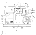
- Fig. 3 is a view of the movable body 2 and the transport unit 3 according to an embodiment as viewed from the X-axis direction.
- the moving body 2 includes a table 10 , a slider block 11 , a magnet 12 , and a linear scale 13 .
- the table 10 has a top plate portion that extends along the XY plane, and a pair of side walls that hang down from both ends of the top plate portion in the Y-axis direction.
- An object to be transported (not shown) can be fixed to the upper surface side of the top plate portion of the table 10.
- a slider block 11 is attached to the underside of the top plate of the table 10.
- the slider block 11 is engaged with the track body 30 so as to be movable in the X-axis direction.
- Recesses are formed on both side surfaces of the track body 30 in the Y-axis direction, and the slider block 11 has protrusions that engage with the recesses.
- a rolling element transfer path for endlessly transferring rolling elements may be formed between the recess of the track body 30 and the protrusion of the slider block 11.
- the rolling element transfer path may be provided, for example, in two rows, one on each side of the track body 30 in the Y-axis direction, or in four rows, two on each side of the track body 30 in the Y-axis direction.
- a magnet 12 is attached to the underside of the top plate of the table 10.
- the magnet 12 is disposed on the -Y side of the slider block 11.
- the magnetic poles of the magnet 12 face downward.
- the downward magnetic poles of the magnet 12 are arranged so that the N poles and S poles are alternately arranged in the X-axis direction.
- a linear scale 13 is attached to the inner wall surface of the side wall on the +Y side of the table 10.
- the linear scale 13 is formed in the shape of a thin rod extending in the X-axis direction.
- the linear scale 13 faces the detection unit 64a of the linear encoder 60 in the Y-axis direction.
- the linear scale 13 and the linear encoder 60 may be either optical or magnetic.
- the transport unit 3 comprises a base member 20, a track body 30, a coil unit 40, a drive board 50, a linear encoder 60, and a cover 70.
- the base member 20 comprises a bottom plate portion 21, a first column portion 22, and a second column portion 23.
- the bottom plate portion 21 is formed in a plate shape extending along the X-Y plane.
- the first column portion 22 stands upward (towards the +Z side) from the centre of the bottom plate portion 21 in the Y-axis direction.
- the track body 30 described above is attached to the top of the first column portion 22.
- the first column portion 22 extends in the X-axis direction together with the track body 30.
- a first mounting portion 22a (step) is formed on the surface of the first column portion 22 facing the -Y side.
- the second pillar portion 23 is disposed on the -Y side of the first pillar portion 22, and stands upward (to the +Z side) from the bottom plate portion 21.
- the second pillar portion 23 also extends in the X-axis direction together with the first pillar portion 22 (first mounting portion 22a).
- the height of the top of the second pillar portion 23 is the same as the height of the first mounting portion 22a.
- a support member 41 is installed between the second pillar portion 23 and the first mounting portion 22a.
- the support member 41 is formed in an L-shape when viewed from the X-axis direction.
- the support member 41 supports the coil unit 40.
- the coil unit 40 faces the magnet 12 in the Z-axis direction.
- the coil unit 40 has U-phase, V-phase, and W-phase coil groups aligned along the X-axis direction. For example, multiple coil units 40 (four in this embodiment) are arranged side by side in the X-axis direction.
- the drive board 50 is disposed below the coil unit 40 (-Z side) and is fixed onto the bottom plate portion 21.
- the drive board 50 is connected to the coil unit 40 via a cable (not shown), and controls the movement of the moving body 2 in the X-axis direction by passing a current through the coil unit 40.
- the drive board 50 is disposed so as to penetrate the first column portion 22 in the Y-axis direction.
- the cover 70 covers the portion of the drive board 50 that protrudes from the first column portion 22 to the +Y side.
- the cover 70 is provided with various connectors that connect the drive board 50 to an external device (not shown).
- reference numerals 71 and 72 in FIG. 2 are communication connectors.
- Reference numeral 73 is a power connector.
- Reference numeral 74 is a USB connector.
- a second mounting portion 22b (step) is formed on the surface of the first column portion 22 facing the +Y side.
- a linear encoder 60 is attached to the second mounting portion 22b. As shown in FIG. 3, the linear encoder 60 is formed in an L-shape when viewed from the X-axis direction.
- the linear encoder 60 includes a mounting base 61, a positioning plate 62, a sensor cover 63, and a position detection sensor 64.
- the mounting base 61 is formed in a plate shape extending along the X-Y plane, and is fixed to the second mounting portion 22b.
- a positioning plate 62 is attached to the +Y side end of the mounting base 61 by a screw member 61a.
- the positioning plate 62 stands upright above (on the +Z side) the +Y side end of the mounting base 61.
- the positioning plate 62 extends along the X-Z plane.
- the positioning plate 62 extends along the movement direction (X-axis direction) of the movable body 2 and faces the linear scale 13 in the Y-axis direction.
- a protective film 62a is attached to the surface of the positioning plate 62 facing the linear scale 13.
- the surface of the positioning plate 62 not facing the linear scale 13 is covered by a sensor cover 63.
- a sensor board 65 which will be described later, is arranged inside the sensor cover 63.
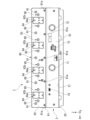
- FIG. 4 is a view of the transport unit 3 according to one embodiment as viewed from the Y-axis direction.
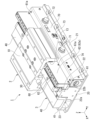
- FIG. 5 is a rear perspective view of the linear encoder 60 according to one embodiment.
- FIG. 6 is a rear perspective view of the mounting base 61 and positioning plate 62 according to one embodiment.
- FIG. 7 is a cross-sectional view taken along the line VII-VII shown in FIG. 4. Note that in these figures, the protective film 62a of the positioning plate 62 is not shown in order to improve visibility.
- the linear encoder 60 has a sensor board 65.
- a position detection sensor 64 is provided on one surface 65A of the sensor board 65 facing the +Y side (linear scale 13 side).
- multiple position detection sensors 64 are provided on the sensor board 65 at intervals in the X-axis direction.
- the positioning plate 62 has a number of windows 62b in the portion facing the position detection sensors 64.
- the positioning plate 62 has a number of windows 62b (four in this embodiment) spaced apart in the X-axis direction.
- the window portions 62b in this embodiment are rectangular openings formed in the positioning plate 62, the shape is not limited to a rectangular shape as long as it corresponds to the position detection sensors 64.
- the sensor board 65 is fixed to the positioning plate 62 by fixing parts 80, which will be described later.
- the fixing parts 80 are provided on both sides in the X-axis direction of each of the multiple position detection sensors 64.
- the elements of the position detection sensor 64 (including the detection part 64a) are arranged in the window part 62b with one surface 65A of the sensor board 65 abutting against the positioning plate 62.
- the mounting base 61 is formed with a first fixing hole 61b, a second fixing hole 61c, and an elongated hole 61d.
- a screw member (not shown) is disposed in the first fixing hole 61b to attach the mounting base 61 to the second mounting portion 22b (see FIG. 2 and FIG. 3).
- a plurality of first fixing holes 61b are formed at intervals in the X-axis direction along the edge of the mounting base 61 on the -Y side.
- the second fixing hole 61c is formed on the mounting base 61 on the +Y side of the first fixing hole 61b.
- a screw member 92 that fixes the sensor cover 63 in the Z-axis direction from below is placed in the second fixing hole 61c.
- the sensor cover 63 is also fixed in the Y-axis direction to multiple fixed cylinders 91 fixed to the positioning plate 62 by a screw member (not shown).
- the long hole 61d is formed along the edge of the mounting base 61 on the +Y side.
- a connection wire (not shown) that can be connected to a connector 65a provided on the other surface 65B of the sensor board 65 is arranged in the long hole 61d.
- the connection wire electrically connects the sensor board 65 and the drive board 50.
- the other surface 65B of the sensor board 65 is the surface facing the -Y side, and is the surface opposite to the one surface 65A facing the +Y side (linear scale 13 side).
- a positioning protrusion 61e that positions the sensor board 65 in the X-axis direction is formed on the +X side of the long hole 61d of the mounting base 61.
- the positioning protrusion 61e stands upright from the +Y side edge of the mounting base 61 toward the upward (+Z side).
- a positioning recess 65b that engages with the positioning protrusion 61e is formed on the lower edge of the sensor board 65.
- the positioning recess 65b is recessed toward the upward (+Z side).
- the fixing part 80 includes a support member 81 provided on the positioning plate 62, a collar member 82 that is movable in the Y-axis direction along the support member 81, and a fastening member 83 that fastens and fixes the collar member 82 to the support member 81.
- the support member 81 is positioned differently from the fixed tube 91 (see FIG. 6) described above, but has the same configuration.
- the support member 81 is formed in a cylindrical shape extending from the positioning plate 62 to the -Y side.
- a female thread is formed on the inner peripheral surface of the support member 81.
- the support member 81 is made of metal, and is fixed to the positioning plate 62 by caulking, as shown in FIG. 7.
- a deformed portion 81a with a larger diameter than the outer peripheral surface of the support member 81 is formed on the end of the support member 81 on the +Y side.
- the deformed portion 81a Before being crimped to the positioning plate 62, the deformed portion 81a has an expansion portion that is larger than the fixing hole 62c formed in the positioning plate 62. This deformed portion 81a is positioned in the fixing hole 62c, and the expansion portion is pressed into the fixing hole 62c using a press or the like. This causes the expansion portion to deform, and the support member 81 can be fixed to the positioning plate 62.
- the collar member 82 is made of resin and is formed into a cylindrical shape that can slide in the Y-axis direction along the outer circumferential surface of the support member 81.
- a ring-shaped flange portion 82a with a larger diameter than the outer circumferential surface of the collar member 82 is formed on the end of the collar member 82 on the +Y side.
- the flange portion 82a abuts against the other surface 65B of the sensor board 65 and fixes (clamps) the sensor board 65 between it and the positioning plate 62.
- the fastening member 83 comprises a screw member 83a and a washer member 83b.
- the screw member 83a is screwed into the support member 81 from the -Y side.
- the washer member 83b is interposed between the opening edge on the -Y side of the collar member 82 and the head of the screw member 83a. Note that if the outer diameter of the head of the screw member 83a is larger than the inner diameter of the collar member 82, it is not necessarily necessary to provide the washer member 83b.
- the sensor board 65 has a through hole 65c that penetrates from one surface 65A to the other surface 65B and into which the support member 81 is inserted.
- the outer diameter of the flange 82a of the collar member 82 is larger than the inner diameter of the through hole 65c.
- the only error factor in the dimension of the gap G1 between the position detection sensor 64 and the linear scale 13 is the height H1 of the element of the position detection sensor 64.
- the thickness of the sensor substrate 65 and the like are no longer an error factor in the dimension of the gap G1. This makes it possible to precisely manage the dimension of the gap G1 between the position detection sensor 64 and the linear scale 13.
- the linear encoder 60 of this embodiment includes a sensor board 65, a plurality of position detection sensors 64 provided on one surface 65A of the sensor board 65, a positioning plate 62 having a plurality of window portions 62b provided in a portion facing the plurality of position detection sensors 64, and a fixing portion 80 for fixing the sensor board 65 to the positioning plate 62, and the plurality of position detection sensors 64 are arranged in the plurality of window portions 62b with the one surface 65A of the sensor board 65 abutting the positioning plate 62.
- the dimension of the gap G1 between the position detection sensors 64 and the linear scale 13 can be controlled with high precision.
- the fixing portion 80 is provided on both sides of each of the multiple position detection sensors 64.
- one surface 65A of the sensor substrate 65 is in contact with the positioning plate 62 at least on both sides of the position detection sensor 64. This allows the dimension of the gap G1 between the position detection sensor 64 and the linear scale 13 to be managed with greater precision.
- the fixing portion 80 includes a support member 81 provided on the positioning plate 62, a collar member 82 movable along the support member 81, and a fastening member 83 that fastens the collar member 82 to the support member 81.
- the sensor board 65 has a through hole 65c that penetrates from one surface 65A to the other surface 65B and into which the support member 81 is inserted.
- the collar member 82 abuts against the other surface 65B of the sensor board 65 while being fastened to the support member 81.
- the one surface 65A of the sensor board 65 can be tightly attached to the positioning plate 62 without the fixing portion 80 protruding toward the linear scale 13 side (+Y side). This makes it possible to reduce the gap G1.
- the support member 81 is fixed to the positioning plate 62 by crimping.
- distortion of the positioning plate 62 is less likely to occur compared to when the support member 81 is welded to the positioning plate 62.
- This allows the dimension of the gap G1 between the position detection sensor 64 and the linear scale 13 to be controlled with greater precision.
- the positioning plate 62 and support member 81 may be formed by, for example, machining, although this requires more processing costs than crimping.
- the linear transport system 1 of this embodiment also includes a moving body 2 equipped with a linear scale 13, a track body 30 that guides the moving body 2, and a transport unit 3 equipped with a linear encoder 60 that is arranged along the track body 30 and can face the linear scale 13, and multiple transport units 3 can be connected so that multiple track bodies 30 are continuous.
- a moving body 2 equipped with a linear scale 13, a track body 30 that guides the moving body 2
- a transport unit 3 equipped with a linear encoder 60 that is arranged along the track body 30 and can face the linear scale 13, and multiple transport units 3 can be connected so that multiple track bodies 30 are continuous.
- the gap dimension between the position detection sensor and the linear scale can be managed with high precision.
Landscapes
- Physics & Mathematics (AREA)
- General Physics & Mathematics (AREA)
- Transmission And Conversion Of Sensor Element Output (AREA)
- Measurement Of Length, Angles, Or The Like Using Electric Or Magnetic Means (AREA)
Abstract
Description
本発明は、リニアエンコーダ及びリニア搬送システムに関するものである。本願は、2023年6月9日に日本に出願された特願2023-095687号に基づき優先権を主張し、その内容をここに援用する。 The present invention relates to a linear encoder and a linear conveying system. This application claims priority to Japanese Patent Application No. 2023-095687, filed on June 9, 2023, the contents of which are incorporated herein by reference.
下記特許文献1には、誘導型位置トランスデューサ素子を用いた電子スケールが開示されている。この電子スケールは、第一部材と、前記第一部材が移動可能な測定軸を有する細長いビーム部材と、駆動信号に応答し、磁束域内で変動磁束を発生する少なくとも1つの磁場発生器と、前記磁束域内に配置でき、その近傍の変調域内で前記変動磁束を変更可能な少なくとも1つの磁束変調器と、前記磁束域内に配置され、前記磁束域内の変動磁束を検出し、その検出された磁束に基づいて、それと前記少なくとも1つの磁束変調器との間の相対位置を示す出力信号を生成する少なくとも1つの磁束センサと、を含み、前記各磁場発生器および前記各磁束センサは、連続的な空間的に変調された誘導結合を形成する。
上記のようなリニアエンコーダにおいて、高精度の測定を行うためには、位置検出センサとリニアスケールとのギャップ寸法を精度良く管理する必要がある。 In order to perform highly accurate measurements with a linear encoder like the one described above, it is necessary to precisely control the gap dimensions between the position detection sensor and the linear scale.
本発明は、上記事情に鑑みてなされたものであり、位置検出センサとリニアスケールとのギャップ寸法を精度良く管理できるリニアエンコーダ及びリニア搬送システムの提供を目的とする。 The present invention was made in consideration of the above circumstances, and aims to provide a linear encoder and linear transport system that can accurately manage the gap dimension between the position detection sensor and the linear scale.
本発明の第1態様は、センサ基板と、前記センサ基板の一方の面に設けられた複数の位置検出センサと、前記複数の位置検出センサに対向する部分に、複数の窓部が設けられた位置決めプレートと、前記位置決めプレートに前記センサ基板を固定する固定部と、を備え、前記複数の位置検出センサは、前記センサ基板の前記一方の面が前記位置決めプレートに当接した状態で、前記複数の窓部内に配置されている。 The first aspect of the present invention comprises a sensor board, a plurality of position detection sensors provided on one surface of the sensor board, a positioning plate having a plurality of window portions provided in a portion facing the plurality of position detection sensors, and a fixing portion for fixing the sensor board to the positioning plate, and the plurality of position detection sensors are disposed within the plurality of window portions with the one surface of the sensor board abutting against the positioning plate.
本発明の第2態様は、前記固定部は、前記複数の位置検出センサの各々の両側に設けられている、前記第1態様のリニアエンコーダである。 The second aspect of the present invention is the linear encoder of the first aspect, in which the fixed portion is provided on both sides of each of the multiple position detection sensors.
本発明の第3態様は、前記固定部は、前記位置決めプレートに設けられた支柱部材と、前記支柱部材に沿って移動可能なカラー部材と、前記カラー部材を前記支柱部材に締結固定する締結部材と、を備え、前記センサ基板には、前記一方の面から他方の面に貫通し、前記支柱部材が挿入される貫通孔が形成され、前記カラー部材は、前記支柱部材に締結固定された状態で、前記センサ基板の前記他方の面に当接している、前記第1態様または前記第2態様のリニアエンコーダである。 The third aspect of the present invention is a linear encoder according to the first or second aspect, in which the fixing portion comprises a support member provided on the positioning plate, a collar member movable along the support member, and a fastening member fastening the collar member to the support member, the sensor board has a through hole penetrating from the one surface to the other surface into which the support member is inserted, and the collar member abuts against the other surface of the sensor board while being fastened to the support member.
本発明の第4態様は、前記支柱部材は、前記位置決めプレートに対してカシメにより固定されている、前記第3態様のリニアエンコーダである。 The fourth aspect of the present invention is the linear encoder of the third aspect, in which the support member is fixed to the positioning plate by crimping.
本発明の第5態様は、リニアスケールを備える移動体と、前記移動体を案内する軌道体、及び、前記軌道体に沿って配置され、前記リニアスケールに対向可能なリニアエンコーダを備える搬送ユニットと、を備え、複数の前記搬送ユニットは、複数の前記軌道体が連続するように連結可能であり、前記リニアエンコーダは、前記第1態様または前記第2態様のリニアエンコーダである、リニア搬送システムである。 The fifth aspect of the present invention is a linear transport system comprising a moving body having a linear scale, a track body that guides the moving body, and a transport unit that is arranged along the track body and has a linear encoder that can face the linear scale, wherein a plurality of the transport units can be connected so that a plurality of the track bodies are continuous, and the linear encoder is the linear encoder of the first aspect or the second aspect.
本発明の一態様によれば、位置検出センサとリニアスケールとのギャップ寸法を精度良く管理できる。 According to one aspect of the present invention, the gap dimension between the position detection sensor and the linear scale can be managed with high precision.
以下、本発明の一実施形態について図面を参照して説明する。 Below, one embodiment of the present invention will be described with reference to the drawings.
図1は、一実施形態に係るリニア搬送システム1の全体図である。
リニア搬送システム1は、図1に示すように、移動体2と、搬送ユニット3と、を備えている。搬送ユニット3は、移動体2を案内する軌道体30と、軌道体30に沿って配置されたリニアエンコーダ60と、を備えている。
FIG. 1 is an overall view of a
1, the
複数の搬送ユニット3は、複数の軌道体30が連続するように連結可能とされている。図1の例では、3台の搬送ユニット3が連結されている。搬送ユニット3の軌道体30と、それと隣り合う搬送ユニット3の軌道体30との間には、連結レール31が配設されている。移動体2は、連結レール31によって1本に連結された隣り合う軌道体30に沿って移動可能とされている。
The
なお、以下の説明において、XYZ直交座標系を設定し、このXYZ直交座標系を参照しつつ各部材の位置関係について説明することがある。X軸方向は、軌道体30が延びる長さ方向(移動体2の移動方向)である。Y軸方向は、X軸方向と直交する軌道体30の幅方向である。Z軸方向は、X軸方向及びY軸方向と直交する軌道体30の高さ方向である。
In the following description, an XYZ Cartesian coordinate system is set, and the positional relationships of each component may be described with reference to this XYZ Cartesian coordinate system. The X-axis direction is the length direction of the track body 30 (the direction of movement of the moving body 2). The Y-axis direction is the width direction of the
図2は、一実施形態に係る移動体2及び搬送ユニット3の斜視図である。図3は、一実施形態に係る移動体2及び搬送ユニット3をX軸方向から視た図である。
図3に示すように、移動体2は、テーブル10と、スライダブロック11と、マグネット12と、リニアスケール13と、を備えている。
Fig. 2 is a perspective view of the
As shown in FIG. 3, the
テーブル10は、X-Y平面に沿って延びる天板部と、天板部のうちY軸方向の両端部から下方に垂設される一対の側壁部と、を備えている。テーブル10の天板部の上面側には、図示しない搬送対象物が固定可能とされている。 The table 10 has a top plate portion that extends along the XY plane, and a pair of side walls that hang down from both ends of the top plate portion in the Y-axis direction. An object to be transported (not shown) can be fixed to the upper surface side of the top plate portion of the table 10.
テーブル10の天板部の下面側には、スライダブロック11が取り付けられている。スライダブロック11は、軌道体30に対して、X軸方向に移動可能に係合している。軌道体30のうちY軸方向の両側の側面には、凹部が形成され、スライダブロック11は、当該凹部に係合する凸部を備えている。
A
なお、軌道体30の凹部とスライダブロック11の凸部との間には、図示しない転動体を無端転送させる転動体転送路が形成されてもよい。当該転動体転送路は、例えば、Y軸方向における軌道体30の両側に1列ずつ計2列で設けられてもよく、またY軸方向における軌道体30の両側に2列ずつ計4列で設けられてもよい。
A rolling element transfer path for endlessly transferring rolling elements (not shown) may be formed between the recess of the
また、テーブル10の天板部の下面側には、マグネット12が取り付けられている。マグネット12は、スライダブロック11の-Y側に配置されている。マグネット12の磁極は、下方を向いている。マグネット12の下向きの磁極は、N極、S極がX軸方向において交互に並ぶように配設されている。
Furthermore, a
テーブル10の+Y側の側壁部の内壁面には、リニアスケール13が取り付けられている。リニアスケール13は、X軸方向に延びる薄板の棒状に形成されている。リニアスケール13は、リニアエンコーダ60の検出部64aとY軸方向において対向している。なお、リニアスケール13及びリニアエンコーダ60は、光学式であっても磁気式であってもよい。
A
搬送ユニット3は、ベース部材20と、軌道体30と、コイルユニット40と、駆動基板50と、リニアエンコーダ60と、カバー70と、を備えている。ベース部材20は、底板部21と、第1柱部22と、第2柱部23と、を備えている。底板部21は、X-Y平面に沿って延びる板状に形成されている。
The
第1柱部22は、底板部21のうちY軸方向の中央部から上方(+Z側)に向かって立設している。第1柱部22の頂部には、上述した軌道体30が取り付けられている。第1柱部22は、図2に示すように、軌道体30と共にX軸方向に延在している。第1柱部22の-Y側を向く面には、第1取付部22a(段差)が形成されている。
The
第2柱部23は、第1柱部22の-Y側に配置され、底板部21から上方(+Z側)に向かって立設している。第2柱部23も、第1柱部22(第1取付部22a)と共にX軸方向に延在している。第2柱部23の頂部の高さは、第1取付部22aの高さと同じとされている。第2柱部23と第1取付部22aとの間には、支持部材41が架設されている。
The
支持部材41は、図3に示すように、X軸方向から視てL字状に形成されている。支持部材41は、コイルユニット40を支持している。コイルユニット40は、Z軸方向においてマグネット12と対向している。コイルユニット40は、U相、V相、W相のコイル群をX軸方向に沿って備えている。このコイルユニット40は、例えば、X軸方向に複数台(本実施形態では4台)並んで設けられている。
As shown in FIG. 3, the
駆動基板50は、図3に示すように、コイルユニット40の下方(-Z側)に配置され、底板部21上に固定されている。駆動基板50は、図示しないケーブルを介してコイルユニット40と接続され、コイルユニット40に電流を流して、移動体2のX軸方向の移動を制御する。駆動基板50は、第1柱部22をY軸方向に貫通して配置されている。
As shown in FIG. 3, the
カバー70は、駆動基板50の第1柱部22より+Y側に突出した部分を覆っている。カバー70には、駆動基板50と、図示しない外部装置とを接続する各種コネクタが設けられている。例えば、図2に示す符号71、72は、通信コネクタである。また、符号73は、電源コネクタである。また、符号74は、USBコネクタである。
The
第1柱部22の+Y側を向く面には、第2取付部22b(段差)が形成されている。第2取付部22bには、リニアエンコーダ60が取り付けられている。リニアエンコーダ60は、図3に示すように、X軸方向から視てL字状に形成されている。リニアエンコーダ60は、取付ベース61と、位置決めプレート62と、センサカバー63と、位置検出センサ64と、を備えている。
A second mounting
取付ベース61は、X-Y平面に沿って延びる板状に形成され、第2取付部22bに固定されている。取付ベース61の+Y側の端部には、位置決めプレート62がネジ部材61aによって取り付けられている。位置決めプレート62は、取付ベース61の+Y側の端部から上方(+Z側)に立設している。位置決めプレート62は、X-Z平面に沿って延びている。
The mounting
位置決めプレート62は、図2に示すように、移動体2の移動方向(X軸方向)に沿って延び、リニアスケール13とY軸方向で対向している。位置決めプレート62のリニアスケール13との対向面には、保護フィルム62aが貼り付けられている。位置決めプレート62のリニアスケール13との非対向面側は、図3に示すように、センサカバー63によって覆われている。センサカバー63の内側には、後述するセンサ基板65が配置されている。
As shown in FIG. 2, the
図4は、一実施形態に係る搬送ユニット3をY軸方向から視た図である。図5は、一実施形態に係るリニアエンコーダ60の背面側斜視図である。図6は、一実施形態に係る取付ベース61及び位置決めプレート62の背面側斜視図である。図7は、図4に示す矢視VII-VII断面図である。なお、これらの図では、視認性の向上のため、位置決めプレート62の保護フィルム62aは、図示していない。
FIG. 4 is a view of the
図5及び図7に示すように、リニアエンコーダ60は、センサ基板65を備えている。センサ基板65の+Y側(リニアスケール13側)を向く一方の面65Aには、位置検出センサ64が設けられている。位置検出センサ64は、センサ基板65に対し、図4に示すように、X軸方向に間隔をあけて複数(本実施形態では4つ)設けられている。
As shown in Figs. 5 and 7, the
位置決めプレート62は、図4及び図6に示すように、複数の位置検出センサ64に対向する部分に、複数の窓部62bを備えている。つまり、位置決めプレート62には、X軸方向に間隔をあけて複数(本実施形態では4つ)の窓部62bが設けられている。なお、本実施形態の窓部62bは、位置決めプレート62に形成された長方形状の開口であるが、位置検出センサ64に対応する形状であれば長方形状に限定されない。
As shown in Figures 4 and 6, the
センサ基板65は、後述する固定部80によって、位置決めプレート62に固定されている。固定部80は、図4に示すように、複数の位置検出センサ64の各々のX軸方向の両側に設けられている。位置検出センサ64の素子(検出部64aを含む)は、図7に示すように、センサ基板65の一方の面65Aが位置決めプレート62に当接した状態で、窓部62b内に配置されている。
The
図5に示すように、取付ベース61には、第1固定孔61bと、第2固定孔61cと、長孔61dと、が形成されている。第1固定孔61bには、取付ベース61を第2取付部22b(図2及び図3参照)に取り付ける図示しないネジ部材が配置される。第1固定孔61bは、取付ベース61のうち-Y側の端縁に沿って、X軸方向に間隔をあけて複数形成されている。
As shown in FIG. 5, the mounting
第2固定孔61cは、取付ベース61のうち第1固定孔61bより+Y側に形成されている。第2固定孔61cには、センサカバー63を下方からZ軸方向に固定するネジ部材92が配置される。なお、センサカバー63は、位置決めプレート62に固定された複数の固定筒91に対し、図示しないネジ部材によってY軸方向においても固定されている。
The
図5に示すように、長孔61dは、取付ベース61のうち+Y側の端縁に沿って形成されている。長孔61dには、センサ基板65の他方の面65Bに設けられたコネクタ65aと接続可能な図示しない接続配線が配置される。当該接続配線は、センサ基板65と駆動基板50とを電気的に接続する。なお、センサ基板65のうち他方の面65Bとは、-Y側を向く面であって、+Y側(リニアスケール13側)を向く一方の面65Aと逆向きの面である。
As shown in FIG. 5, the
取付ベース61のうち長孔61dの+X側には、センサ基板65をX軸方向に位置決めする位置決め凸部61eが形成されている。位置決め凸部61eは、取付ベース61のうち+Y側の端縁から上方(+Z側)に向かって立設している。センサ基板65の下端縁には、位置決め凸部61eと係合する位置決め凹部65bが形成されている。位置決め凹部65bは、上方(+Z側)に向かって窪んでいる。
A
図7に示すように、固定部80は、位置決めプレート62に設けられた支柱部材81と、支柱部材81に沿ってY軸方向に移動可能なカラー部材82と、カラー部材82を支柱部材81に締結固定する締結部材83と、を備えている。なお、支柱部材81は、上述した固定筒91(図6参照)と位置が異なるが、同じ構成である。
As shown in FIG. 7, the fixing
支柱部材81は、位置決めプレート62から-Y側に延びる円筒状に形成されている。支柱部材81の内周面には、雌ネジが形成されている。支柱部材81は、金属製であって、図7に示すように、位置決めプレート62に対してカシメにより固定されている。支柱部材81の+Y側の端部には、支柱部材81の外周面より拡径した変形部81aが形成されている。
The
変形部81aは、位置決めプレート62に対してカシメられる前は、位置決めプレート62に形成された固定孔62cよりも大きい拡張部を備えている。この変形部81aを固定孔62cに位置決めし、拡張部を固定孔62c内にプレス機等で押し入れる。これにより、拡張部が変形し、支柱部材81を位置決めプレート62に固定できる。
Before being crimped to the
カラー部材82は、樹脂製であって、支柱部材81の外周面に沿ってY軸方向に摺動可能な円筒状に形成されている。カラー部材82のうち+Y側の端部には、カラー部材82の外周面より拡径した円環状の鍔部82aが形成されている。鍔部82aは、センサ基板65のうち他方の面65Bに当接し、位置決めプレート62との間でセンサ基板65を固定(挟持)する。
The
締結部材83は、ネジ部材83aと、座金部材83bと、を備えている。ネジ部材83aは、-Y側から支柱部材81に螺合している。座金部材83bは、カラー部材82の-Y側の開口端縁とネジ部材83aの頭部との間に介在している。なお、ネジ部材83aの頭部の外径が、カラー部材82の内径より大きい場合、必ずしも座金部材83bは設けなくてもよい。
The
センサ基板65には、一方の面65Aから他方の面65Bに貫通し、支柱部材81が挿入される貫通孔65cが形成されている。カラー部材82の鍔部82aの外径は、貫通孔65cの内径よりも大きい。締結部材83(ネジ部材83a)を締め付けると、カラー部材82がセンサ基板65の他方の面65Bに当接し、センサ基板65の一方の面65Aが位置決めプレート62に当接した状態で固定される。
The
この構成によれば、図7に示すように、位置検出センサ64とリニアスケール13とのギャップG1の寸法の誤差要因が、位置検出センサ64の素子の高さH1のみとなる。すなわち、センサ基板65の厚み等がギャップG1の寸法の誤差要因にならなくなる。これにより、位置検出センサ64とリニアスケール13とのギャップG1の寸法を精度よく管理することができる。
With this configuration, as shown in FIG. 7, the only error factor in the dimension of the gap G1 between the
上述したように、本実施形態のリニアエンコーダ60は、センサ基板65と、センサ基板65の一方の面65Aに設けられた複数の位置検出センサ64と、複数の位置検出センサ64に対向する部分に、複数の窓部62bが設けられた位置決めプレート62と、位置決めプレート62にセンサ基板65を固定する固定部80と、を備え、複数の位置検出センサ64は、センサ基板65の一方の面65Aが位置決めプレート62に当接した状態で、複数の窓部62b内に配置されている。この構成によれば、位置検出センサ64とリニアスケール13とのギャップG1の寸法を精度良く管理できる。
As described above, the
また、本実施形態では、固定部80は、複数の位置検出センサ64の各々の両側に設けられている。この構成によれば、少なくとも位置検出センサ64の両側で、センサ基板65の一方の面65Aが位置決めプレート62に当接した状態となる。これにより、位置検出センサ64とリニアスケール13とのギャップG1の寸法をより精度良く管理できる。
In addition, in this embodiment, the fixing
また、本実施形態では、固定部80は、位置決めプレート62に設けられた支柱部材81と、支柱部材81に沿って移動可能なカラー部材82と、カラー部材82を支柱部材81に締結固定する締結部材83と、を備え、センサ基板65には、一方の面65Aから他方の面65Bに貫通し、支柱部材81が挿入される貫通孔65cが形成され、カラー部材82は、支柱部材81に締結固定された状態で、センサ基板65の他方の面65Bに当接している。この構成によれば、固定部80をリニアスケール13側(+Y側)に突出させないで、センサ基板65の一方の面65Aを位置決めプレート62に密着させることができる。これにより、ギャップG1を小さくできる。
In this embodiment, the fixing
また、本実施形態では、支柱部材81は、位置決めプレート62に対してカシメにより固定されている。この構成によれば、支柱部材81を位置決めプレート62に溶接等する場合と比べて、位置決めプレート62に歪みが生じ難くなる。これにより、位置検出センサ64とリニアスケール13とのギャップG1の寸法をより精度良く管理できる。なお、カシメよりも加工コストがかかるが、位置決めプレート62及び支柱部材81を、例えば削り出しにより形成してもよい。
In addition, in this embodiment, the
また、本実施形態のリニア搬送システム1は、リニアスケール13を備える移動体2と、移動体2を案内する軌道体30、及び、軌道体30に沿って配置され、リニアスケール13に対向可能なリニアエンコーダ60を備える搬送ユニット3と、を備え、複数の搬送ユニット3は、複数の軌道体30が連続するように連結可能である。この構成によれば、一台一台の搬送ユニット3において位置検出センサ64とリニアスケール13とのギャップG1の寸法を精度良く管理できる。これにより、搬送ユニット3を複数台連結しても、リニア搬送システム1全体としての移動体2の位置検出精度を高めることができる。
The
以上、図面を参照しながら本発明の好適な実施形態について説明したが、本発明は上記実施形態に限定されるものではない。上述した実施形態において示した各構成部材の諸形状や組み合わせ等は一例であって、本発明の主旨から逸脱しない範囲において設計要求等に基づき種々変更可能である。 The above describes a preferred embodiment of the present invention with reference to the drawings, but the present invention is not limited to the above embodiment. The shapes and combinations of the components shown in the above embodiment are merely examples, and various modifications can be made based on design requirements, etc., without departing from the spirit of the present invention.
本発明の一態様によれば、位置検出センサとリニアスケールとのギャップ寸法を精度良く管理できる。 According to one aspect of the present invention, the gap dimension between the position detection sensor and the linear scale can be managed with high precision.
1 リニア搬送システム
2 移動体
3 搬送ユニット
13 リニアスケール
30 軌道体
60 リニアエンコーダ
62 位置決めプレート
62b 窓部
64 位置検出センサ
64a 検出部
65 センサ基板
65A 一方の面
65B 他方の面
80 固定部
81 支柱部材
82 カラー部材
83 締結部材
H1 素子高さ
G1 ギャップ
REFERENCE SIGNS
Claims (5)
前記センサ基板の一方の面に設けられた複数の位置検出センサと、
前記複数の位置検出センサに対向する部分に、複数の窓部が設けられた位置決めプレートと、
前記位置決めプレートに前記センサ基板を固定する固定部と、
を備え、
前記複数の位置検出センサは、前記センサ基板の前記一方の面が前記位置決めプレートに当接した状態で、前記複数の窓部内に配置されている、
リニアエンコーダ。 A sensor substrate;
A plurality of position detection sensors provided on one surface of the sensor substrate;
a positioning plate having a plurality of windows in a portion facing the plurality of position detection sensors;
a fixing portion that fixes the sensor substrate to the positioning plate;
Equipped with
the plurality of position detection sensors are disposed in the plurality of windows with the one surface of the sensor substrate in contact with the positioning plate;
Linear encoder.
請求項1に記載のリニアエンコーダ。 The fixing portion is provided on both sides of each of the plurality of position detection sensors.
2. The linear encoder according to claim 1.
前記位置決めプレートに設けられた支柱部材と、
前記支柱部材に沿って移動可能なカラー部材と、
前記カラー部材を前記支柱部材に締結固定する締結部材と、
を備え、
前記センサ基板には、前記一方の面から他方の面に貫通し、前記支柱部材が挿入される貫通孔が形成され、
前記カラー部材は、前記支柱部材に締結固定された状態で、前記センサ基板の前記他方の面に当接している、
請求項1または2に記載のリニアエンコーダ。 The fixing portion is
A support member provided on the positioning plate;
a collar member movable along the support member;
a fastening member for fastening the collar member to the support member;
Equipped with
a through hole is formed in the sensor substrate, the through hole penetrating from the one surface to the other surface and into which the support member is inserted;
the collar member is fastened to the support member and abuts against the other surface of the sensor board;
3. The linear encoder according to claim 1 or 2.
請求項3に記載のリニアエンコーダ。 The support member is fixed to the positioning plate by caulking.
4. The linear encoder according to claim 3.
前記移動体を案内する軌道体、及び、前記軌道体に沿って配置され、前記リニアスケールに対向可能なリニアエンコーダを備える搬送ユニットと、
を備え、
複数の前記搬送ユニットは、複数の前記軌道体が連続するように連結可能であり、
前記リニアエンコーダは、請求項1または2に記載のリニアエンコーダである、
リニア搬送システム。 A moving body having a linear scale;
a conveying unit including a track body that guides the moving body, and a linear encoder that is arranged along the track body and can face the linear scale;
Equipped with
The plurality of transport units are connectable to each other so that the plurality of track bodies are continuous,
The linear encoder is the linear encoder according to claim 1 or 2.
Linear transport system.
Priority Applications (2)
| Application Number | Priority Date | Filing Date | Title |
|---|---|---|---|
| CN202480037622.3A CN121311740A (en) | 2023-06-09 | 2024-05-28 | Linear encoders and linear transport systems |
| KR1020257040651A KR20260018844A (en) | 2023-06-09 | 2024-05-28 | Linear encoders and linear conveying systems |
Applications Claiming Priority (2)
| Application Number | Priority Date | Filing Date | Title |
|---|---|---|---|
| JP2023-095687 | 2023-06-09 | ||
| JP2023095687A JP2024176851A (en) | 2023-06-09 | 2023-06-09 | Linear Encoder and Linear Conveyor System |
Publications (1)
| Publication Number | Publication Date |
|---|---|
| WO2024252991A1 true WO2024252991A1 (en) | 2024-12-12 |
Family
ID=93795922
Family Applications (1)
| Application Number | Title | Priority Date | Filing Date |
|---|---|---|---|
| PCT/JP2024/019598 Ceased WO2024252991A1 (en) | 2023-06-09 | 2024-05-28 | Linear encoder and linear conveyance system |
Country Status (5)
| Country | Link |
|---|---|
| JP (1) | JP2024176851A (en) |
| KR (1) | KR20260018844A (en) |
| CN (1) | CN121311740A (en) |
| TW (1) | TW202503459A (en) |
| WO (1) | WO2024252991A1 (en) |
Citations (3)
| Publication number | Priority date | Publication date | Assignee | Title |
|---|---|---|---|---|
| JP2013250244A (en) * | 2012-06-04 | 2013-12-12 | Nidec Sankyo Corp | Magnetic sensor device |
| JP2015050831A (en) * | 2013-08-30 | 2015-03-16 | ヤマハ発動機株式会社 | Linear conveyor |
| JP2019138716A (en) * | 2018-02-08 | 2019-08-22 | 日本電産サンキョー株式会社 | Magnetic sensor device and position detector |
Family Cites Families (1)
| Publication number | Priority date | Publication date | Assignee | Title |
|---|---|---|---|---|
| US6002250A (en) | 1996-05-13 | 1999-12-14 | Mitutoyo Corporation | Electronic linear scale using a self-contained, low-power inductive position transducer |
-
2023
- 2023-06-09 JP JP2023095687A patent/JP2024176851A/en active Pending
-
2024
- 2024-05-28 CN CN202480037622.3A patent/CN121311740A/en active Pending
- 2024-05-28 KR KR1020257040651A patent/KR20260018844A/en active Pending
- 2024-05-28 WO PCT/JP2024/019598 patent/WO2024252991A1/en not_active Ceased
- 2024-06-05 TW TW113120726A patent/TW202503459A/en unknown
Patent Citations (3)
| Publication number | Priority date | Publication date | Assignee | Title |
|---|---|---|---|---|
| JP2013250244A (en) * | 2012-06-04 | 2013-12-12 | Nidec Sankyo Corp | Magnetic sensor device |
| JP2015050831A (en) * | 2013-08-30 | 2015-03-16 | ヤマハ発動機株式会社 | Linear conveyor |
| JP2019138716A (en) * | 2018-02-08 | 2019-08-22 | 日本電産サンキョー株式会社 | Magnetic sensor device and position detector |
Also Published As
| Publication number | Publication date |
|---|---|
| JP2024176851A (en) | 2024-12-19 |
| TW202503459A (en) | 2025-01-16 |
| CN121311740A (en) | 2026-01-09 |
| KR20260018844A (en) | 2026-02-09 |
Similar Documents
| Publication | Publication Date | Title |
|---|---|---|
| US7633188B2 (en) | Sliding device with onboard moving-magnet linear motor | |
| US6195261B1 (en) | Device for positioning integrated circuit components that require specific spatial orientation | |
| JP7154879B2 (en) | Portal structure positioning device | |
| EP2866337B1 (en) | Slider for linear conveyer and linear conveyer | |
| US6911747B2 (en) | X-Y stage system with onboard linear motor | |
| KR890005596A (en) | Positioning feedback method and apparatus on the restricted area of the movable member | |
| US12287247B2 (en) | Measurement system for installation between torque and/or force-transmitting machine parts | |
| US6441515B1 (en) | Linear motor | |
| WO2024252991A1 (en) | Linear encoder and linear conveyance system | |
| JP2015049109A (en) | Linear conveyor | |
| EP1445584B1 (en) | Scale device | |
| JP4154089B2 (en) | Scale unit connection member | |
| CN100440565C (en) | Magnetoresistive element | |
| CN101349534B (en) | Length measuring device | |
| JP2006194815A (en) | Eddy current flaw detection multi-coil probe and its manufacuring method | |
| US5924214A (en) | Length measuring apparatus for measuring the relative position of two objects | |
| JP3218328B2 (en) | Bending type three-dimensional structure circuit device | |
| JP2015050831A (en) | Linear conveyor | |
| US12384634B2 (en) | Conveyance device | |
| US12479084B2 (en) | Multi-axis operation apparatus in opposite arrangement | |
| US20200041309A1 (en) | Sensor system and method for determining a position of a measuring element along a motion path | |
| CN108779992A (en) | Encoder apparatus and motion guide device with encoder apparatus | |
| US11201533B2 (en) | Planar positioning device | |
| US20250364478A1 (en) | Die bonding apparatus and die positioning method using the die bonding apparatus | |
| US20240167845A1 (en) | Method for adjusting an inertial sensor component by means of a calibration device, calibration device, base device and inertial sensor component |
Legal Events
| Date | Code | Title | Description |
|---|---|---|---|
| 121 | Ep: the epo has been informed by wipo that ep was designated in this application |
Ref document number: 24819222 Country of ref document: EP Kind code of ref document: A1 |