WO2024252991A1 - Codeur linéaire et système de transport linéaire - Google Patents
Codeur linéaire et système de transport linéaire Download PDFInfo
- Publication number
- WO2024252991A1 WO2024252991A1 PCT/JP2024/019598 JP2024019598W WO2024252991A1 WO 2024252991 A1 WO2024252991 A1 WO 2024252991A1 JP 2024019598 W JP2024019598 W JP 2024019598W WO 2024252991 A1 WO2024252991 A1 WO 2024252991A1
- Authority
- WO
- WIPO (PCT)
- Prior art keywords
- positioning plate
- linear
- support member
- position detection
- linear encoder
- Prior art date
- Legal status (The legal status is an assumption and is not a legal conclusion. Google has not performed a legal analysis and makes no representation as to the accuracy of the status listed.)
- Ceased
Links
Images



Classifications
-
- G—PHYSICS
- G01—MEASURING; TESTING
- G01B—MEASURING LENGTH, THICKNESS OR SIMILAR LINEAR DIMENSIONS; MEASURING ANGLES; MEASURING AREAS; MEASURING IRREGULARITIES OF SURFACES OR CONTOURS
- G01B7/00—Measuring arrangements characterised by the use of electric or magnetic techniques
- G01B7/003—Measuring arrangements characterised by the use of electric or magnetic techniques for measuring position, not involving coordinate determination
-
- G—PHYSICS
- G01—MEASURING; TESTING
- G01B—MEASURING LENGTH, THICKNESS OR SIMILAR LINEAR DIMENSIONS; MEASURING ANGLES; MEASURING AREAS; MEASURING IRREGULARITIES OF SURFACES OR CONTOURS
- G01B7/00—Measuring arrangements characterised by the use of electric or magnetic techniques
-
- G—PHYSICS
- G01—MEASURING; TESTING
- G01D—MEASURING NOT SPECIALLY ADAPTED FOR A SPECIFIC VARIABLE; ARRANGEMENTS FOR MEASURING TWO OR MORE VARIABLES NOT COVERED IN A SINGLE OTHER SUBCLASS; TARIFF METERING APPARATUS; MEASURING OR TESTING NOT OTHERWISE PROVIDED FOR
- G01D5/00—Mechanical means for transferring the output of a sensing member; Means for converting the output of a sensing member to another variable where the form or nature of the sensing member does not constrain the means for converting; Transducers not specially adapted for a specific variable
- G01D5/12—Mechanical means for transferring the output of a sensing member; Means for converting the output of a sensing member to another variable where the form or nature of the sensing member does not constrain the means for converting; Transducers not specially adapted for a specific variable using electric or magnetic means
- G01D5/244—Mechanical means for transferring the output of a sensing member; Means for converting the output of a sensing member to another variable where the form or nature of the sensing member does not constrain the means for converting; Transducers not specially adapted for a specific variable using electric or magnetic means influencing characteristics of pulses or pulse trains; generating pulses or pulse trains
-
- G—PHYSICS
- G01—MEASURING; TESTING
- G01D—MEASURING NOT SPECIALLY ADAPTED FOR A SPECIFIC VARIABLE; ARRANGEMENTS FOR MEASURING TWO OR MORE VARIABLES NOT COVERED IN A SINGLE OTHER SUBCLASS; TARIFF METERING APPARATUS; MEASURING OR TESTING NOT OTHERWISE PROVIDED FOR
- G01D5/00—Mechanical means for transferring the output of a sensing member; Means for converting the output of a sensing member to another variable where the form or nature of the sensing member does not constrain the means for converting; Transducers not specially adapted for a specific variable
- G01D5/12—Mechanical means for transferring the output of a sensing member; Means for converting the output of a sensing member to another variable where the form or nature of the sensing member does not constrain the means for converting; Transducers not specially adapted for a specific variable using electric or magnetic means
- G01D5/244—Mechanical means for transferring the output of a sensing member; Means for converting the output of a sensing member to another variable where the form or nature of the sensing member does not constrain the means for converting; Transducers not specially adapted for a specific variable using electric or magnetic means influencing characteristics of pulses or pulse trains; generating pulses or pulse trains
- G01D5/245—Mechanical means for transferring the output of a sensing member; Means for converting the output of a sensing member to another variable where the form or nature of the sensing member does not constrain the means for converting; Transducers not specially adapted for a specific variable using electric or magnetic means influencing characteristics of pulses or pulse trains; generating pulses or pulse trains using a variable number of pulses in a train
-
- G—PHYSICS
- G01—MEASURING; TESTING
- G01D—MEASURING NOT SPECIALLY ADAPTED FOR A SPECIFIC VARIABLE; ARRANGEMENTS FOR MEASURING TWO OR MORE VARIABLES NOT COVERED IN A SINGLE OTHER SUBCLASS; TARIFF METERING APPARATUS; MEASURING OR TESTING NOT OTHERWISE PROVIDED FOR
- G01D5/00—Mechanical means for transferring the output of a sensing member; Means for converting the output of a sensing member to another variable where the form or nature of the sensing member does not constrain the means for converting; Transducers not specially adapted for a specific variable
- G01D5/26—Mechanical means for transferring the output of a sensing member; Means for converting the output of a sensing member to another variable where the form or nature of the sensing member does not constrain the means for converting; Transducers not specially adapted for a specific variable characterised by optical transfer means, i.e. using infrared, visible, or ultraviolet light
- G01D5/32—Mechanical means for transferring the output of a sensing member; Means for converting the output of a sensing member to another variable where the form or nature of the sensing member does not constrain the means for converting; Transducers not specially adapted for a specific variable characterised by optical transfer means, i.e. using infrared, visible, or ultraviolet light with attenuation or whole or partial obturation of beams of light
- G01D5/34—Mechanical means for transferring the output of a sensing member; Means for converting the output of a sensing member to another variable where the form or nature of the sensing member does not constrain the means for converting; Transducers not specially adapted for a specific variable characterised by optical transfer means, i.e. using infrared, visible, or ultraviolet light with attenuation or whole or partial obturation of beams of light the beams of light being detected by photocells
- G01D5/347—Mechanical means for transferring the output of a sensing member; Means for converting the output of a sensing member to another variable where the form or nature of the sensing member does not constrain the means for converting; Transducers not specially adapted for a specific variable characterised by optical transfer means, i.e. using infrared, visible, or ultraviolet light with attenuation or whole or partial obturation of beams of light the beams of light being detected by photocells using displacement encoding scales
- G01D5/34746—Linear encoders
-
- G—PHYSICS
- G01—MEASURING; TESTING
- G01D—MEASURING NOT SPECIALLY ADAPTED FOR A SPECIFIC VARIABLE; ARRANGEMENTS FOR MEASURING TWO OR MORE VARIABLES NOT COVERED IN A SINGLE OTHER SUBCLASS; TARIFF METERING APPARATUS; MEASURING OR TESTING NOT OTHERWISE PROVIDED FOR
- G01D5/00—Mechanical means for transferring the output of a sensing member; Means for converting the output of a sensing member to another variable where the form or nature of the sensing member does not constrain the means for converting; Transducers not specially adapted for a specific variable
- G01D5/26—Mechanical means for transferring the output of a sensing member; Means for converting the output of a sensing member to another variable where the form or nature of the sensing member does not constrain the means for converting; Transducers not specially adapted for a specific variable characterised by optical transfer means, i.e. using infrared, visible, or ultraviolet light
- G01D5/32—Mechanical means for transferring the output of a sensing member; Means for converting the output of a sensing member to another variable where the form or nature of the sensing member does not constrain the means for converting; Transducers not specially adapted for a specific variable characterised by optical transfer means, i.e. using infrared, visible, or ultraviolet light with attenuation or whole or partial obturation of beams of light
- G01D5/34—Mechanical means for transferring the output of a sensing member; Means for converting the output of a sensing member to another variable where the form or nature of the sensing member does not constrain the means for converting; Transducers not specially adapted for a specific variable characterised by optical transfer means, i.e. using infrared, visible, or ultraviolet light with attenuation or whole or partial obturation of beams of light the beams of light being detected by photocells
- G01D5/347—Mechanical means for transferring the output of a sensing member; Means for converting the output of a sensing member to another variable where the form or nature of the sensing member does not constrain the means for converting; Transducers not specially adapted for a specific variable characterised by optical transfer means, i.e. using infrared, visible, or ultraviolet light with attenuation or whole or partial obturation of beams of light the beams of light being detected by photocells using displacement encoding scales
- G01D5/34746—Linear encoders
- G01D5/34753—Carriages; Driving or coupling means
Definitions
- the present invention relates to a linear encoder and a linear conveying system.
- Patent Document 1 discloses an electronic scale using an inductive position transducer element.
- This electronic scale includes a first member, an elongated beam member having a measurement axis along which the first member can move, at least one magnetic field generator that generates a fluctuating magnetic flux in a magnetic flux field in response to a drive signal, at least one magnetic flux modulator that can be arranged in the magnetic flux field and can change the fluctuating magnetic flux in a modulation field nearby, and at least one magnetic flux sensor that is arranged in the magnetic flux field, detects the fluctuating magnetic flux in the magnetic flux field, and generates an output signal indicative of a relative position between it and the at least one magnetic flux modulator based on the detected magnetic flux, and each of the magnetic field generators and each of the magnetic flux sensors forms a continuous spatially modulated inductive coupling.
- the present invention was made in consideration of the above circumstances, and aims to provide a linear encoder and linear transport system that can accurately manage the gap dimension between the position detection sensor and the linear scale.
- the first aspect of the present invention comprises a sensor board, a plurality of position detection sensors provided on one surface of the sensor board, a positioning plate having a plurality of window portions provided in a portion facing the plurality of position detection sensors, and a fixing portion for fixing the sensor board to the positioning plate, and the plurality of position detection sensors are disposed within the plurality of window portions with the one surface of the sensor board abutting against the positioning plate.
- the second aspect of the present invention is the linear encoder of the first aspect, in which the fixed portion is provided on both sides of each of the multiple position detection sensors.
- the third aspect of the present invention is a linear encoder according to the first or second aspect, in which the fixing portion comprises a support member provided on the positioning plate, a collar member movable along the support member, and a fastening member fastening the collar member to the support member, the sensor board has a through hole penetrating from the one surface to the other surface into which the support member is inserted, and the collar member abuts against the other surface of the sensor board while being fastened to the support member.
- the fourth aspect of the present invention is the linear encoder of the third aspect, in which the support member is fixed to the positioning plate by crimping.
- the fifth aspect of the present invention is a linear transport system comprising a moving body having a linear scale, a track body that guides the moving body, and a transport unit that is arranged along the track body and has a linear encoder that can face the linear scale, wherein a plurality of the transport units can be connected so that a plurality of the track bodies are continuous, and the linear encoder is the linear encoder of the first aspect or the second aspect.
- the gap dimension between the position detection sensor and the linear scale can be managed with high precision.
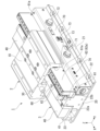
- FIG. 1 is an overall view of a linear transport system according to an embodiment
- FIG. 2 is a perspective view of a moving body and a transport unit according to an embodiment.
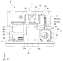
- FIG. 2 is a diagram showing a movable body and a transport unit according to an embodiment as viewed from the X-axis direction.
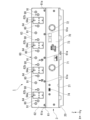
- FIG. 2 is a diagram showing a transport unit according to an embodiment as viewed from the Y-axis direction.
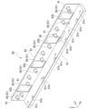
- FIG. 2 is a rear perspective view of a linear encoder according to an embodiment;
- FIG. 1 is an overall view of a linear transport system 1 according to an embodiment.
- the linear transport system 1 includes a moving body 2 and a transport unit 3.
- the transport unit 3 includes a track body 30 that guides the moving body 2, and a linear encoder 60 disposed along the track body 30.
- the multiple transport units 3 can be connected so that the multiple track bodies 30 are continuous.
- three transport units 3 are connected.
- a connecting rail 31 is provided between the track body 30 of one transport unit 3 and the track body 30 of the adjacent transport unit 3.
- the moving body 2 can move along the adjacent track bodies 30 that are connected together by the connecting rail 31.
- the X-axis direction is the length direction of the track body 30 (the direction of movement of the moving body 2).
- the Y-axis direction is the width direction of the track body 30, which is perpendicular to the X-axis direction.
- the Z-axis direction is the height direction of the track body 30, which is perpendicular to the X-axis and Y-axis directions.
- Fig. 2 is a perspective view of the movable body 2 and the transport unit 3 according to an embodiment.
- Fig. 3 is a view of the movable body 2 and the transport unit 3 according to an embodiment as viewed from the X-axis direction.
- the moving body 2 includes a table 10 , a slider block 11 , a magnet 12 , and a linear scale 13 .
- the table 10 has a top plate portion that extends along the XY plane, and a pair of side walls that hang down from both ends of the top plate portion in the Y-axis direction.
- An object to be transported (not shown) can be fixed to the upper surface side of the top plate portion of the table 10.
- a slider block 11 is attached to the underside of the top plate of the table 10.
- the slider block 11 is engaged with the track body 30 so as to be movable in the X-axis direction.
- Recesses are formed on both side surfaces of the track body 30 in the Y-axis direction, and the slider block 11 has protrusions that engage with the recesses.
- a rolling element transfer path for endlessly transferring rolling elements may be formed between the recess of the track body 30 and the protrusion of the slider block 11.
- the rolling element transfer path may be provided, for example, in two rows, one on each side of the track body 30 in the Y-axis direction, or in four rows, two on each side of the track body 30 in the Y-axis direction.
- a magnet 12 is attached to the underside of the top plate of the table 10.
- the magnet 12 is disposed on the -Y side of the slider block 11.
- the magnetic poles of the magnet 12 face downward.
- the downward magnetic poles of the magnet 12 are arranged so that the N poles and S poles are alternately arranged in the X-axis direction.
- a linear scale 13 is attached to the inner wall surface of the side wall on the +Y side of the table 10.
- the linear scale 13 is formed in the shape of a thin rod extending in the X-axis direction.
- the linear scale 13 faces the detection unit 64a of the linear encoder 60 in the Y-axis direction.
- the linear scale 13 and the linear encoder 60 may be either optical or magnetic.
- the transport unit 3 comprises a base member 20, a track body 30, a coil unit 40, a drive board 50, a linear encoder 60, and a cover 70.
- the base member 20 comprises a bottom plate portion 21, a first column portion 22, and a second column portion 23.
- the bottom plate portion 21 is formed in a plate shape extending along the X-Y plane.
- the first column portion 22 stands upward (towards the +Z side) from the centre of the bottom plate portion 21 in the Y-axis direction.
- the track body 30 described above is attached to the top of the first column portion 22.
- the first column portion 22 extends in the X-axis direction together with the track body 30.
- a first mounting portion 22a (step) is formed on the surface of the first column portion 22 facing the -Y side.
- the second pillar portion 23 is disposed on the -Y side of the first pillar portion 22, and stands upward (to the +Z side) from the bottom plate portion 21.
- the second pillar portion 23 also extends in the X-axis direction together with the first pillar portion 22 (first mounting portion 22a).
- the height of the top of the second pillar portion 23 is the same as the height of the first mounting portion 22a.
- a support member 41 is installed between the second pillar portion 23 and the first mounting portion 22a.
- the support member 41 is formed in an L-shape when viewed from the X-axis direction.
- the support member 41 supports the coil unit 40.
- the coil unit 40 faces the magnet 12 in the Z-axis direction.
- the coil unit 40 has U-phase, V-phase, and W-phase coil groups aligned along the X-axis direction. For example, multiple coil units 40 (four in this embodiment) are arranged side by side in the X-axis direction.
- the drive board 50 is disposed below the coil unit 40 (-Z side) and is fixed onto the bottom plate portion 21.
- the drive board 50 is connected to the coil unit 40 via a cable (not shown), and controls the movement of the moving body 2 in the X-axis direction by passing a current through the coil unit 40.
- the drive board 50 is disposed so as to penetrate the first column portion 22 in the Y-axis direction.
- the cover 70 covers the portion of the drive board 50 that protrudes from the first column portion 22 to the +Y side.
- the cover 70 is provided with various connectors that connect the drive board 50 to an external device (not shown).
- reference numerals 71 and 72 in FIG. 2 are communication connectors.
- Reference numeral 73 is a power connector.
- Reference numeral 74 is a USB connector.
- a second mounting portion 22b (step) is formed on the surface of the first column portion 22 facing the +Y side.
- a linear encoder 60 is attached to the second mounting portion 22b. As shown in FIG. 3, the linear encoder 60 is formed in an L-shape when viewed from the X-axis direction.
- the linear encoder 60 includes a mounting base 61, a positioning plate 62, a sensor cover 63, and a position detection sensor 64.
- the mounting base 61 is formed in a plate shape extending along the X-Y plane, and is fixed to the second mounting portion 22b.
- a positioning plate 62 is attached to the +Y side end of the mounting base 61 by a screw member 61a.
- the positioning plate 62 stands upright above (on the +Z side) the +Y side end of the mounting base 61.
- the positioning plate 62 extends along the X-Z plane.
- the positioning plate 62 extends along the movement direction (X-axis direction) of the movable body 2 and faces the linear scale 13 in the Y-axis direction.
- a protective film 62a is attached to the surface of the positioning plate 62 facing the linear scale 13.
- the surface of the positioning plate 62 not facing the linear scale 13 is covered by a sensor cover 63.
- a sensor board 65 which will be described later, is arranged inside the sensor cover 63.
- FIG. 4 is a view of the transport unit 3 according to one embodiment as viewed from the Y-axis direction.
- FIG. 5 is a rear perspective view of the linear encoder 60 according to one embodiment.
- FIG. 6 is a rear perspective view of the mounting base 61 and positioning plate 62 according to one embodiment.
- FIG. 7 is a cross-sectional view taken along the line VII-VII shown in FIG. 4. Note that in these figures, the protective film 62a of the positioning plate 62 is not shown in order to improve visibility.
- the linear encoder 60 has a sensor board 65.
- a position detection sensor 64 is provided on one surface 65A of the sensor board 65 facing the +Y side (linear scale 13 side).
- multiple position detection sensors 64 are provided on the sensor board 65 at intervals in the X-axis direction.
- the positioning plate 62 has a number of windows 62b in the portion facing the position detection sensors 64.
- the positioning plate 62 has a number of windows 62b (four in this embodiment) spaced apart in the X-axis direction.
- the window portions 62b in this embodiment are rectangular openings formed in the positioning plate 62, the shape is not limited to a rectangular shape as long as it corresponds to the position detection sensors 64.
- the sensor board 65 is fixed to the positioning plate 62 by fixing parts 80, which will be described later.
- the fixing parts 80 are provided on both sides in the X-axis direction of each of the multiple position detection sensors 64.
- the elements of the position detection sensor 64 (including the detection part 64a) are arranged in the window part 62b with one surface 65A of the sensor board 65 abutting against the positioning plate 62.
- the mounting base 61 is formed with a first fixing hole 61b, a second fixing hole 61c, and an elongated hole 61d.
- a screw member (not shown) is disposed in the first fixing hole 61b to attach the mounting base 61 to the second mounting portion 22b (see FIG. 2 and FIG. 3).
- a plurality of first fixing holes 61b are formed at intervals in the X-axis direction along the edge of the mounting base 61 on the -Y side.
- the second fixing hole 61c is formed on the mounting base 61 on the +Y side of the first fixing hole 61b.
- a screw member 92 that fixes the sensor cover 63 in the Z-axis direction from below is placed in the second fixing hole 61c.
- the sensor cover 63 is also fixed in the Y-axis direction to multiple fixed cylinders 91 fixed to the positioning plate 62 by a screw member (not shown).
- the long hole 61d is formed along the edge of the mounting base 61 on the +Y side.
- a connection wire (not shown) that can be connected to a connector 65a provided on the other surface 65B of the sensor board 65 is arranged in the long hole 61d.
- the connection wire electrically connects the sensor board 65 and the drive board 50.
- the other surface 65B of the sensor board 65 is the surface facing the -Y side, and is the surface opposite to the one surface 65A facing the +Y side (linear scale 13 side).
- a positioning protrusion 61e that positions the sensor board 65 in the X-axis direction is formed on the +X side of the long hole 61d of the mounting base 61.
- the positioning protrusion 61e stands upright from the +Y side edge of the mounting base 61 toward the upward (+Z side).
- a positioning recess 65b that engages with the positioning protrusion 61e is formed on the lower edge of the sensor board 65.
- the positioning recess 65b is recessed toward the upward (+Z side).
- the fixing part 80 includes a support member 81 provided on the positioning plate 62, a collar member 82 that is movable in the Y-axis direction along the support member 81, and a fastening member 83 that fastens and fixes the collar member 82 to the support member 81.
- the support member 81 is positioned differently from the fixed tube 91 (see FIG. 6) described above, but has the same configuration.
- the support member 81 is formed in a cylindrical shape extending from the positioning plate 62 to the -Y side.
- a female thread is formed on the inner peripheral surface of the support member 81.
- the support member 81 is made of metal, and is fixed to the positioning plate 62 by caulking, as shown in FIG. 7.
- a deformed portion 81a with a larger diameter than the outer peripheral surface of the support member 81 is formed on the end of the support member 81 on the +Y side.
- the deformed portion 81a Before being crimped to the positioning plate 62, the deformed portion 81a has an expansion portion that is larger than the fixing hole 62c formed in the positioning plate 62. This deformed portion 81a is positioned in the fixing hole 62c, and the expansion portion is pressed into the fixing hole 62c using a press or the like. This causes the expansion portion to deform, and the support member 81 can be fixed to the positioning plate 62.
- the collar member 82 is made of resin and is formed into a cylindrical shape that can slide in the Y-axis direction along the outer circumferential surface of the support member 81.
- a ring-shaped flange portion 82a with a larger diameter than the outer circumferential surface of the collar member 82 is formed on the end of the collar member 82 on the +Y side.
- the flange portion 82a abuts against the other surface 65B of the sensor board 65 and fixes (clamps) the sensor board 65 between it and the positioning plate 62.
- the fastening member 83 comprises a screw member 83a and a washer member 83b.
- the screw member 83a is screwed into the support member 81 from the -Y side.
- the washer member 83b is interposed between the opening edge on the -Y side of the collar member 82 and the head of the screw member 83a. Note that if the outer diameter of the head of the screw member 83a is larger than the inner diameter of the collar member 82, it is not necessarily necessary to provide the washer member 83b.
- the sensor board 65 has a through hole 65c that penetrates from one surface 65A to the other surface 65B and into which the support member 81 is inserted.
- the outer diameter of the flange 82a of the collar member 82 is larger than the inner diameter of the through hole 65c.
- the only error factor in the dimension of the gap G1 between the position detection sensor 64 and the linear scale 13 is the height H1 of the element of the position detection sensor 64.
- the thickness of the sensor substrate 65 and the like are no longer an error factor in the dimension of the gap G1. This makes it possible to precisely manage the dimension of the gap G1 between the position detection sensor 64 and the linear scale 13.
- the linear encoder 60 of this embodiment includes a sensor board 65, a plurality of position detection sensors 64 provided on one surface 65A of the sensor board 65, a positioning plate 62 having a plurality of window portions 62b provided in a portion facing the plurality of position detection sensors 64, and a fixing portion 80 for fixing the sensor board 65 to the positioning plate 62, and the plurality of position detection sensors 64 are arranged in the plurality of window portions 62b with the one surface 65A of the sensor board 65 abutting the positioning plate 62.
- the dimension of the gap G1 between the position detection sensors 64 and the linear scale 13 can be controlled with high precision.
- the fixing portion 80 is provided on both sides of each of the multiple position detection sensors 64.
- one surface 65A of the sensor substrate 65 is in contact with the positioning plate 62 at least on both sides of the position detection sensor 64. This allows the dimension of the gap G1 between the position detection sensor 64 and the linear scale 13 to be managed with greater precision.
- the fixing portion 80 includes a support member 81 provided on the positioning plate 62, a collar member 82 movable along the support member 81, and a fastening member 83 that fastens the collar member 82 to the support member 81.
- the sensor board 65 has a through hole 65c that penetrates from one surface 65A to the other surface 65B and into which the support member 81 is inserted.
- the collar member 82 abuts against the other surface 65B of the sensor board 65 while being fastened to the support member 81.
- the one surface 65A of the sensor board 65 can be tightly attached to the positioning plate 62 without the fixing portion 80 protruding toward the linear scale 13 side (+Y side). This makes it possible to reduce the gap G1.
- the support member 81 is fixed to the positioning plate 62 by crimping.
- distortion of the positioning plate 62 is less likely to occur compared to when the support member 81 is welded to the positioning plate 62.
- This allows the dimension of the gap G1 between the position detection sensor 64 and the linear scale 13 to be controlled with greater precision.
- the positioning plate 62 and support member 81 may be formed by, for example, machining, although this requires more processing costs than crimping.
- the linear transport system 1 of this embodiment also includes a moving body 2 equipped with a linear scale 13, a track body 30 that guides the moving body 2, and a transport unit 3 equipped with a linear encoder 60 that is arranged along the track body 30 and can face the linear scale 13, and multiple transport units 3 can be connected so that multiple track bodies 30 are continuous.
- a moving body 2 equipped with a linear scale 13, a track body 30 that guides the moving body 2
- a transport unit 3 equipped with a linear encoder 60 that is arranged along the track body 30 and can face the linear scale 13, and multiple transport units 3 can be connected so that multiple track bodies 30 are continuous.
- the gap dimension between the position detection sensor and the linear scale can be managed with high precision.
Landscapes
- Physics & Mathematics (AREA)
- General Physics & Mathematics (AREA)
- Transmission And Conversion Of Sensor Element Output (AREA)
- Measurement Of Length, Angles, Or The Like Using Electric Or Magnetic Means (AREA)
Abstract
La présente invention concerne un codeur linéaire (60) comprenant : un substrat de capteur (65) ; des capteurs de détection de position (64) disposés sur une surface (65A) du substrat de capteur (65) ; une plaque de positionnement (62) avec des fenêtres (62b) disposées sur des parties faisant face aux capteurs de détection de position (64) ; et des unités de fixation (80) qui fixent le substrat de capteur (65) à la plaque de positionnement (62). Les capteurs de détection de position (64) sont agencés dans les fenêtres (62b) dans un état où la surface (65A) du substrat de capteur (65) est en contact avec la plaque de positionnement (62).
Priority Applications (3)
| Application Number | Priority Date | Filing Date | Title |
|---|---|---|---|
| KR1020257040651A KR20260018844A (ko) | 2023-06-09 | 2024-05-28 | 리니어 인코더 및 리니어 반송 시스템 |
| CN202480037622.3A CN121311740A (zh) | 2023-06-09 | 2024-05-28 | 线性编码器以及线性搬运系统 |
| DE112024002474.2T DE112024002474T5 (de) | 2023-06-09 | 2024-05-28 | Linearenkoder und lineares Transportsystem |
Applications Claiming Priority (2)
| Application Number | Priority Date | Filing Date | Title |
|---|---|---|---|
| JP2023-095687 | 2023-06-09 | ||
| JP2023095687A JP2024176851A (ja) | 2023-06-09 | 2023-06-09 | リニアエンコーダ及びリニア搬送システム |
Publications (1)
| Publication Number | Publication Date |
|---|---|
| WO2024252991A1 true WO2024252991A1 (fr) | 2024-12-12 |
Family
ID=93795922
Family Applications (1)
| Application Number | Title | Priority Date | Filing Date |
|---|---|---|---|
| PCT/JP2024/019598 Ceased WO2024252991A1 (fr) | 2023-06-09 | 2024-05-28 | Codeur linéaire et système de transport linéaire |
Country Status (6)
| Country | Link |
|---|---|
| JP (1) | JP2024176851A (fr) |
| KR (1) | KR20260018844A (fr) |
| CN (1) | CN121311740A (fr) |
| DE (1) | DE112024002474T5 (fr) |
| TW (1) | TW202503459A (fr) |
| WO (1) | WO2024252991A1 (fr) |
Citations (3)
| Publication number | Priority date | Publication date | Assignee | Title |
|---|---|---|---|---|
| JP2013250244A (ja) * | 2012-06-04 | 2013-12-12 | Nidec Sankyo Corp | 磁気センサ装置 |
| JP2015050831A (ja) * | 2013-08-30 | 2015-03-16 | ヤマハ発動機株式会社 | リニアコンベア |
| JP2019138716A (ja) * | 2018-02-08 | 2019-08-22 | 日本電産サンキョー株式会社 | 磁気センサ装置および位置検出装置 |
Family Cites Families (2)
| Publication number | Priority date | Publication date | Assignee | Title |
|---|---|---|---|---|
| US6002250A (en) | 1996-05-13 | 1999-12-14 | Mitutoyo Corporation | Electronic linear scale using a self-contained, low-power inductive position transducer |
| JP7651125B2 (ja) | 2021-12-24 | 2025-03-26 | 株式会社大一商会 | 遊技機 |
-
2023
- 2023-06-09 JP JP2023095687A patent/JP2024176851A/ja active Pending
-
2024
- 2024-05-28 KR KR1020257040651A patent/KR20260018844A/ko active Pending
- 2024-05-28 WO PCT/JP2024/019598 patent/WO2024252991A1/fr not_active Ceased
- 2024-05-28 DE DE112024002474.2T patent/DE112024002474T5/de active Pending
- 2024-05-28 CN CN202480037622.3A patent/CN121311740A/zh active Pending
- 2024-06-05 TW TW113120726A patent/TW202503459A/zh unknown
Patent Citations (3)
| Publication number | Priority date | Publication date | Assignee | Title |
|---|---|---|---|---|
| JP2013250244A (ja) * | 2012-06-04 | 2013-12-12 | Nidec Sankyo Corp | 磁気センサ装置 |
| JP2015050831A (ja) * | 2013-08-30 | 2015-03-16 | ヤマハ発動機株式会社 | リニアコンベア |
| JP2019138716A (ja) * | 2018-02-08 | 2019-08-22 | 日本電産サンキョー株式会社 | 磁気センサ装置および位置検出装置 |
Also Published As
| Publication number | Publication date |
|---|---|
| KR20260018844A (ko) | 2026-02-09 |
| CN121311740A (zh) | 2026-01-09 |
| JP2024176851A (ja) | 2024-12-19 |
| TW202503459A (zh) | 2025-01-16 |
| DE112024002474T5 (de) | 2026-05-13 |
Similar Documents
| Publication | Publication Date | Title |
|---|---|---|
| US6195261B1 (en) | Device for positioning integrated circuit components that require specific spatial orientation | |
| JP7154879B2 (ja) | 門形構造の位置決め装置 | |
| EP2866337B1 (fr) | Curseur pour un transporteur linéaire et un transporteur linéaire | |
| KR890005596A (ko) | 가동부재의 제한된 영역상의 위치 조정 피드백 방법 및 장치 | |
| WO2018055709A1 (fr) | Dispositif de transporteur linéaire | |
| CN113295190A (zh) | 能够容易调节的行程传感器 | |
| US6441515B1 (en) | Linear motor | |
| JP6129689B2 (ja) | リニアコンベア | |
| US12384634B2 (en) | Conveyance device | |
| JP2024176851A (ja) | リニアエンコーダ及びリニア搬送システム | |
| EP1445584B1 (fr) | Dispositif d'echelle | |
| JP4154089B2 (ja) | スケールユニットの連結部材 | |
| CN100440565C (zh) | 磁阻元件 | |
| JP6117056B2 (ja) | リニアコンベア | |
| CN101349534B (zh) | 长度测量装置 | |
| US11201533B2 (en) | Planar positioning device | |
| US5924214A (en) | Length measuring apparatus for measuring the relative position of two objects | |
| JP3218328B2 (ja) | 折曲型3次元構造回路装置 | |
| US12479084B2 (en) | Multi-axis operation apparatus in opposite arrangement | |
| US20200041309A1 (en) | Sensor system and method for determining a position of a measuring element along a motion path | |
| US7489054B2 (en) | Planar direct drive unit comprising a position measuring system | |
| KR20210006838A (ko) | 위치 측정 장치 | |
| US20250364478A1 (en) | Die bonding apparatus and die positioning method using the die bonding apparatus | |
| CN110081915B (zh) | 磁式线性编码器 | |
| JPS6133885A (ja) | 支持装置 |
Legal Events
| Date | Code | Title | Description |
|---|---|---|---|
| 121 | Ep: the epo has been informed by wipo that ep was designated in this application |
Ref document number: 24819222 Country of ref document: EP Kind code of ref document: A1 |
|
| WWE | Wipo information: entry into national phase |
Ref document number: 112024002474 Country of ref document: DE |
|
| WWP | Wipo information: published in national office |
Ref document number: 112024002474 Country of ref document: DE |
|
| 122 | Ep: pct application non-entry in european phase |
Ref document number: 24819222 Country of ref document: EP Kind code of ref document: A1 |