WO2024252999A1 - 微粒子測定装置および微粒子測定方法 - Google Patents
微粒子測定装置および微粒子測定方法 Download PDFInfo
- Publication number
- WO2024252999A1 WO2024252999A1 PCT/JP2024/019658 JP2024019658W WO2024252999A1 WO 2024252999 A1 WO2024252999 A1 WO 2024252999A1 JP 2024019658 W JP2024019658 W JP 2024019658W WO 2024252999 A1 WO2024252999 A1 WO 2024252999A1
- Authority
- WO
- WIPO (PCT)
- Prior art keywords
- liquid chamber
- clogging
- measuring device
- pore
- particle
- Prior art date
- Legal status (The legal status is an assumption and is not a legal conclusion. Google has not performed a legal analysis and makes no representation as to the accuracy of the status listed.)
- Pending
Links
Images


Classifications
-
- G—PHYSICS
- G01—MEASURING; TESTING
- G01N—INVESTIGATING OR ANALYSING MATERIALS BY DETERMINING THEIR CHEMICAL OR PHYSICAL PROPERTIES
- G01N15/00—Investigating characteristics of particles; Investigating permeability, pore-volume or surface-area of porous materials
- G01N15/10—Investigating individual particles
- G01N15/1031—Investigating individual particles by measuring electrical or magnetic effects
- G01N15/12—Investigating individual particles by measuring electrical or magnetic effects by observing changes in resistance or impedance across apertures when traversed by individual particles, e.g. by using the Coulter principle
- G01N15/13—Details pertaining to apertures
Definitions
- a method for measuring particle size distribution is known as the electrical sensing zone method (Coulter principle).
- an electrolyte containing particles is passed through a fine hole called a nanopore.
- the electrolyte in the pore decreases by an amount equivalent to the volume of the particle, increasing the electrical resistance of the pore. Therefore, the volume of the particle (i.e., the particle size) can be measured by measuring the electrical resistance of the pore.
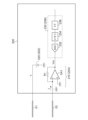
- FIG. 1 is a block diagram of a particle measuring device 1R using the electrical sensing zone method.
- the particle measuring device 1R includes a pore device 100R, a measuring instrument 200R, and a processing device 300.
- the inside of the pore device 100R is filled with an electrolyte solution 2 containing particles 4 to be detected.
- the inside of the pore device 100R is separated into two spaces by a pore chip 102, and electrodes 106 and 108 are provided in the two spaces.
- electrodes 106 and 108 are provided in the two spaces.
- Is Vb/Rp...(1)
- the transimpedance amplifier 210 converts the minute current Is into a voltage signal Vs.
- Vs -r ⁇ Is...(2)
- equation (3) is obtained.
- Vs -Vb ⁇ r/Rp...(3)
- the digitizer 230 converts the voltage signal Vs into digital data Ds. In this manner, the measuring device 200R can obtain a voltage signal Vs that is inversely proportional to the resistance value Rp of the pore 104.
- the processing device 300 processes the digital data Ds and analyzes the number and particle size distribution of the particles 4 contained in the electrolyte 2.
- the resistance value Rp of the pore 104 increases. Therefore, the current Is decreases in a pulsed manner each time a particle passes through. The amplitude of each pulse current correlates with the particle size.
- the particles to be detected or other contained substances may block the pores (pore clogging).
- pore clogging occurs, measurement becomes impossible.
- a method of reversing the direction of electrophoresis has been proposed. In the configuration of FIG. 1, when clogging is detected, the voltage source 220 reverses the polarity of the bias voltage applied to the electrodes 106 and 108. This pushes the substance that has clogged the pore back to the opposite side, clearing the clogging.
- an electrophoretic force is generated by a current of several mA to several hundred mA, but specifically, when measuring current using pores with diameters on the order of ⁇ m to nm, only tens of nA to tens of ⁇ A can be passed.
- polarity reversal changes the chemical state around the electrode.
- the voltage-current curve of the electrode-solution measured by cyclic voltammetry generally has hysteresis, and the same current state may not be obtained even if the same voltage is applied.
- the present disclosure has been made in this context, and one exemplary purpose of one aspect thereof is to provide a particle measuring device that can solve the clogging problem.
- the particle measuring device used in conjunction with a pore device.
- the pore device has a first liquid chamber and a second liquid chamber separated by a partition having fine pores.
- the particle measuring device includes a measuring instrument that measures a current signal flowing between a first electrode provided in the first liquid chamber and a second electrode provided in the second liquid chamber, and a pressure control device that generates a pressure difference between the first liquid chamber and the second liquid chamber when clogging of the pore device is detected during measurement.
- the pore device has a first liquid chamber and a second liquid chamber separated by a partition having a fine pore.
- the method for measuring particulate matter includes the steps of measuring a current signal flowing between a first electrode provided in the first liquid chamber and a second electrode provided in the second liquid chamber, detecting clogging of the pore device during measurement, and generating a pressure difference between the first liquid chamber and the second liquid chamber when clogging is detected.
- Certain aspects of the present disclosure can solve the clogging problem.
- FIG. 1 is a block diagram of a particle measuring device using an electrical sensing zone method.
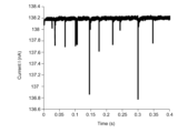
- FIG. 2 is a waveform diagram of an exemplary minute current Is measured by a measuring device.
- FIG. 1 is a diagram showing a particle measuring device according to an embodiment. 4 is a diagram for explaining the operation of the particle measuring device of FIG. 3.
- FIG. 13 is a diagram showing the relationship between pressure and the number of passing particles.
- FIG. 2 is a block diagram of a measuring device according to an embodiment.
- FIG. 1 is a diagram illustrating an example of the configuration of a pressure control device according to an embodiment.
- FIG. 1 is a diagram illustrating an example of the configuration of a pressure control device according to an embodiment.
- the particle measuring device is used together with a pore device.
- the pore device has a first liquid chamber and a second liquid chamber separated by a partition having fine pores.
- the particle measuring device includes a measuring instrument that measures a current signal flowing between a first electrode provided in the first liquid chamber and a second electrode provided in the second liquid chamber, and a pressure control device that generates a pressure difference between the first liquid chamber and the second liquid chamber when clogging of the pore device is detected during measurement.
- clogging does not only refer to a state in which the pore is completely blocked, but can also include a state in which the pore is partially blocked, or a state in which signs of clogging are detected.
- the particle measuring device may include a controller capable of detecting clogging based on a current signal measured by the measuring device.
- the current signal may include a DC component (base current) and an AC component (pulse current) superimposed thereon.
- base current DC component
- AC component pulse current
- the controller may activate the pressure control device upon detecting a clog.
- the current signal obtained while the pressure control device is in operation may not be used for particle measurement.
- the controller may record pressure information (pressure value or state of pressure control device) in a file.
- pressure information pressure value or state of pressure control device
- the section in which clogging was removed can be determined based on the pressure information recorded in this file, making it possible to not use the current signal obtained in this section for particle measurement.
- the controller may stop the pressure control device when it detects that the clogging has been removed based on the current signal. This shortens the period during which measurement is stopped, thereby shortening the measurement time.
- the controller may detect clogging based on the AC component of the current signal. When clogging begins to occur, the frequency of pulses increases. Thus, the controller may detect clogging based on the frequency of pulses.
- the controller may detect clogging based on the DC component of the current signal.
- the DC component of the current signal base current
- the controller may detect clogging based on the decrease in the DC component.
- the measuring device may be capable of reversing the polarity of the voltage applied to the first electrode and the second electrode.
- the pressure control device may generate a pressure difference in a direction corresponding to the polarity of the voltage up to that point.
- the pressure control device may generate a pressure difference by increasing or decreasing the pressure on the first liquid chamber side relative to the atmosphere while the second liquid chamber is open to the atmosphere.
- the measuring instrument may include a transimpedance amplifier that converts the current signal into a voltage signal, and a digitizer that converts the output of the transimpedance amplifier into a digital signal.
- a state in which component A is connected to component B includes not only cases in which component A and component B are directly physically connected, but also cases in which component A and component B are indirectly connected via other components that do not substantially affect their electrical connection state or impair the function or effect achieved by their combination.
- a state in which component C is provided between components A and B includes cases in which components A and C, or components B and C, are directly connected, as well as cases in which they are indirectly connected via other components that do not substantially affect their electrical connection state or impair the function or effect achieved by their combination.
- each component shown in the drawings may be enlarged or reduced as appropriate to facilitate understanding.
- the dimensions of multiple components do not necessarily represent their relative sizes, and even if a component A is shown thicker than another component B in the drawings, component A may actually be thinner than component B.
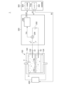
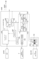
- FIG. 3 is a diagram showing a particle measuring device 1 according to an embodiment.
- the particle measuring device 1 includes a pore device 100, a measuring instrument 200, a processing device 300, and a pressure control device 400.
- the pore device 100 comprises a pore chip 110 and a chip case 120.
- a pore (fine hole) 112 is formed in the pore chip 110.
- the pore chip 110 is housed inside the chip case 120 and divides the internal space of the chip case 120 into a first liquid chamber 122 and a second liquid chamber 124.
- the first liquid chamber 122 and the second liquid chamber 124 are in communication with each other via the pore 112.
- a first electrode E1 is provided in the first liquid chamber 122, and a second electrode E2 is provided in the second liquid chamber 124.
- the internal space of the chip case 120 is filled with electrolyte 2 containing particles 4 to be measured.
- the measuring device 200 applies a voltage V between the first electrode E1 and the second electrode E2, and measures the ion current I flowing between the first electrode E1 and the second electrode E2.
- the measuring device 200 includes a voltage source 202, a current detection circuit 204, and a waveform capture module 206.
- the voltage source 202 generates a potential difference V between the first electrode E1 and the second electrode E2. This potential difference V causes the particles 4 contained in the electrolyte 2 to move by electrophoresis.
- the current detection circuit 204 generates a current detection signal Vcs that indicates the ion current I flowing from the first electrode E1 to the second electrode E2.
- the waveform capture module 206 captures the waveform of the current detection signal Vcs.
- the waveform data WAVE generated by the waveform capture module 206 is transmitted to the processing device 300.
- the processing device 300 has the functions of a controller 302 that controls the entire particle measuring device 1, and a data processing unit 304 that processes the waveform data WAVE and estimates the particle size of the particles 4.
- the processing device 300 may be a combination of hardware such as a general-purpose laptop computer, desktop computer, workstation, or tablet terminal, and a dedicated software program. Alternatively, the processing device 300 may be hardware dedicated to the particle measuring device 1.
- the controller 302 can set the measurement conditions of the measuring device 200 based on the control signal S1.
- the controller 302 generates a control signal S2 that instructs control of the operation and stop of the pressure control device 400 described below.
- the controller 302 can also control the state of the data processing unit 304 based on the control signal S3.
- the data processing unit 304 performs processing such as estimating particle diameter based on the waveform data WAVE.
- the processing device 300 is configured to be able to detect clogging of the pores 112 of the pore device 100.
- the pressure control device 400 is stopped during normal measurement by the measuring device 200. When clogging of the pore device 100 is detected during measurement, the pressure control device 400 generates a pressure difference between the first liquid chamber 122 and the second liquid chamber 124. It is preferable that the pressure is generated in the opposite direction to the movement of the particles due to electrophoresis during measurement.
- the movement direction of the particles in the electrolyte 2 is determined by the direction of the electric field and the charge of the molecules (positive or negative charge). In many cases, the particles to be measured are negatively charged in the solution and therefore move from the negative electrode to the positive electrode.
- the controller 302 has a clogging detection function. Specifically, the controller 302 detects clogging based on the waveform data WAVE of the current signal I from the measuring device 200.
- FIG. 4 is a waveform diagram of the current signal I.
- the current signal I shown in the middle contains a DC component (base current) that flows due to electrophoresis regardless of the presence of particles, and an AC component (pulse current) that is caused by particles passing through the pores 112.
- the upper part of FIG. 4 shows the pulse current corresponding to one particle, and the lower part of FIG. 4 shows the base current.
- FIG. 4 shows a normal state ⁇ 1 in which no clogging has occurred, a state in which clogging is progressing, in other words a state in which a premonition of clogging has occurred (premonition state) ⁇ 2a, and a state in which complete clogging has occurred (completely clogged state) ⁇ 2b.
- the premonition state ⁇ 2a and the completely clogged state ⁇ 2b are collectively referred to as the clogged state ⁇ 2.
- the controller 302 may detect the clogged state ⁇ 2 based on the AC component (pulse current) of the current signal I. As shown in FIG. 4, in the normal state ⁇ 1, a pulse current is observed every time a particle passes through. In contrast, in the precursor state ⁇ 2a, the occurrence of the pulse current is more frequent than in the normal state ⁇ 1. In the completely clogged state ⁇ 2b, the occurrence frequency of the pulse current approaches zero. Therefore, the controller 302 can detect the precursor state ⁇ 2a or the completely clogged state ⁇ 2b based on the occurrence frequency of the pulse current.
- the controller 302 may detect the clogged state ⁇ 2 based on the DC component (base current) of the current signal I. As shown in FIG. 4, in the normal state ⁇ 1, a relatively large base current is observed. In contrast, in the precursor state ⁇ 2a, the base current decreases over time. In the completely clogged state ⁇ 2b, the base current remains very small. Therefore, the controller 302 can detect the precursor state ⁇ 2a or the completely clogged state ⁇ 2b based on the base current.
- the controller 302 may detect the clogging state ⁇ 2 by utilizing characteristic changes in both the pulse current and the base current, thereby further improving the detection accuracy.
- the current measurement by the measuring device 200 continues even while the pressure control device 400 is in operation.
- the controller 302 is configured to monitor the current signal I while the pressure control device 400 is in operation, and detect that the clogged state ⁇ 2 has been resolved, that is, that the state has returned to the normal state ⁇ 1, based on the current signal I.
- the return to the normal state ⁇ 1 can also be detected based on at least one of the base current and pulse current of the current signal I.
- the controller 302 generates a control signal S2 that controls the state of the pressure control device 400 and a control signal S3 that controls the state of the data processing unit 304 depending on whether clogging is present or not.
- the controller 302 detects a clogging state, it activates the pressure control device 400. While the pressure control device 400 is operating, the accuracy of the current signal measured by the measuring device 200 decreases, so the data processing unit 304 stops processing related to particle measurement.
- the controller 302 When the controller 302 detects that the clogging condition has been resolved, it stops the pressure control device 400. It also restarts the processing related to particle measurement by the data processing unit 304.
- FIG. 5 is a diagram explaining the operation of the pore device 100 particle measuring device 1 in FIG. 3.
- the controller 302 detects the precursor state ⁇ 2a.
- the particle measuring device 1 Before time t0 , the particle measuring device 1 operates normally. At time t0 , clogging begins, and pulses with short time intervals begin to be generated in the current signal I. At time t1 , the controller 302 switches the pressure control device 400 to an operating state. When the pressure control device 400 operates, the particles clogging the pores 112 are pushed back toward their original liquid chambers by the pressure of the liquid. This eliminates clogging. While the pressure control device 400 is operating, the particle measuring process by the data processing unit 304 is suspended.
- the controller 302 determines that the clogging has been eliminated at time t2 , it stops the pressure control device 400. Then, at time t3 , it restarts the particle measurement process by the data processing unit 304.
- the above is the operation of the particle measuring device 1.
- electrophoresis is used to move the particles 4 during measurement, while pressure is used to remove clogging, making it possible to remove clogging with a strong force.
- electrolysis of the electrodes and chemical conditions around the electrodes due to polarity reversal are suppressed, enabling accurate measurements.
- FIG. 6 is a block diagram of a measuring device 200A according to one embodiment.
- the measuring device 200A includes a transimpedance amplifier 210, a voltage source 220, and a digitizer 230.
- the voltage source 220 corresponds to the voltage source 202 described above.
- the transimpedance amplifier 210 corresponds to the current detection circuit 204 described above.
- the digitizer 230 corresponds to the waveform capture module 206 described above.
- the transimpedance amplifier 210 includes an operational amplifier OA1 and a resistor R1.
- the inverting input terminal of the operational amplifier OA1 is connected to the first electrode E1, and the non-inverting input terminal is grounded.
- the resistor R1 is connected between the inverting input terminal and the output terminal of the operational amplifier OA1.
- the voltage source 220 applies a voltage V to the first electrode E1. Due to the virtual grounding of the operational amplifier OA1, the potential of the inverting input terminal, i.e., the first electrode E1, becomes ground (0 V). Therefore, the voltage V is applied between the first electrode E1 and the second electrode E2.
- the digitizer 230 includes an A/D converter 232, a memory 234, and an interface circuit 236.
- the A/D converter 232 converts the current detection signal Vcs into a digital signal at a predetermined sampling period.
- the memory 234 stores waveform data.
- the interface circuit 236 transmits the waveform data stored in the memory 234 to the processing device 300.
- FIG. 7 is a diagram showing a pressure control device 400A according to one embodiment.
- the pressure control device 400A includes a pressure source 410A and a control valve 420A.
- the pressure source 410A includes an air pressure pump 412.
- the control valve 420A includes valves V1 and V2. Because sudden pressure changes can damage the pore tip 110, it is preferable to provide a buffer air vent. The state of the control valve 420A is controlled according to a control signal S2 generated by the controller 302.
- valve V1 When the pressure control device 400A is stopped, the valve V1 is in a closed state and the valve V2 can be in a conducting state. Note that the air pressure pump 412 may be stopped while the pressure control device 400A is stopped.
- valve V1 When valve V1 is in a conducting state and valve V2 is in a blocking state, the pressure control device 400A is in an operating state. This allows a pressure difference to be generated between the first liquid chamber 122 and the second liquid chamber 124. Because the first liquid chamber 122 is open to atmospheric pressure, when a positive pressure air pressure pump 412 is used, pressure can be generated from the second liquid chamber 124 toward the first liquid chamber 122. Conversely, when a negative pressure air pressure pump 412 is used, pressure can be generated from the first liquid chamber 122 toward the second liquid chamber 124.
- the measuring device 200 can reverse the polarity of the voltage V applied to the first electrode E1 and the second electrode E2, i.e., the direction of electrophoresis.
- the pressure control device 400 switches the direction of pressure depending on the polarity of the voltage V generated by the measuring device 200, i.e., the direction of electrophoresis. Specifically, it generates a pressure difference so as to push back the particles in the opposite direction to the movement of the particles due to electrophoresis.
- FIG. 8 is a diagram showing a pressure control device 400B according to one embodiment.
- the pressure control device 400B mainly includes clog removal pumps 412A and 412B, valves V1 to V5, an internal power supply 402, a main pump 442, a buffer tank 444, and pressure sensors 446 and 448.
- the internal power supply 402 receives a DC power supply voltage from an external power supply, an AC adapter, and generates an internal power supply voltage that is stabilized at a predetermined voltage level by stepping up or stepping down the voltage.
- the buffer tank 444 is connected to the main pump 442 and accumulates pressure.
- Pressure sensors 446, 448 detect the pressure inside the buffer tank 444 or on the output side.
- the clog removal pump 412A draws in or expels air through port A.
- the clog removal pump 412B draws in or expels air through port B.
- Controller 430 receives control signals from an external DSP (Digital Signal Processor) 4.
- DSP 4 can be part of processing device 300.
- controller 430 controls the states of valves V1 to V5, clog removal pumps 412A and 412B, and main pump 442, and switches the operating mode of pressure control device 400B.
- controller 430 controls main pump 442 based on the outputs of pressure sensors 446 and 448 so that the pressure in buffer tank 444 is constant.
- the first and second modes are modes related to removing clogging as described above.
- Valves V1, V3, and V4 are closed (off), V5 is open (on), and V2 is redundant (DC: Don't care).
- the main pump 442 and the clog removal pump 412B are stopped, and the clog removal pump 412A is in operation.
- pressure is controlled via port A to remove clogs from the pore device 100.
- Valves V1, V2, and V5 are closed (off), V3 is open (on), and V4 is DC.
- the main pump 442 and the unclog pump 412A are stopped, and the unclog pump 412B is operating.
- pressure is controlled via port B to unclog the pore device 100.
- Valve V1 is closed (off), V3 and V5 are open (on), and V2 and V4 are redundant (DC: Don't care) and can be either open or closed.
- the main pump 442 and the clog removal pumps 412A and 412B are stopped.
- the third mode can be selected in the standby state when replacing the pore device 100.
- Valve V1 is closed (off), and valves V2 to V5 are redundant (DC: Don't care).
- the main pump 442 is in an operating state, and the clogging removal pumps 412A and 412B are in a stopped state.
- pressure can be accumulated in the buffer tank 444.
- Valves V1, V2, and V5 are open (ON), and V3 and V4 are closed (OFF).
- the main pump 442 and the clog removal pumps 412A and 412B are stopped.
- the fifth mode can be selected after pressure is accumulated in the buffer tank 444 in the fourth mode, and pressure can be applied to the pore device 100 via port A using the pressure in the buffer tank 444. Note that the main pump 442 may be operated in the fifth mode.
- Valves V1, V3, and V4 are open (ON), and V2 and V5 are closed (OFF).
- the main pump 442 and the clog removal pumps 412A and 412B are stopped.
- the sixth mode can be selected after pressure is accumulated in the buffer tank 444 in the fourth mode, and pressure can be applied to the pore device 100 via port B using the pressure in the buffer tank 444.
- the present specification describes a particle measuring device
- the application of the present invention is not limited to this, and the present invention can be widely used in measuring devices that measure minute currents and are used in conjunction with pore devices, including DNA sequencers.
- the particles are driven by electrophoresis, but the application of this disclosure is not limited to this, and the present disclosure can also be applied to a driving method that uses a concentration gradient to diffuse into a liquid, or a driving method that uses a pressure difference.
- the pressure control device 400B in FIG. 8 can be used for a drive method that utilizes a pressure difference.
- the pump can be stopped while the liquid is being driven, making it possible to perform highly accurate particle measurement without being affected by pump pulsation.
- This disclosure relates to measurements using pore devices.
- 1...particle measuring device 2...electrolyte, 4...particles, 100...pore device, 110...pore tip, 112...pore, 120...tip case, 122...first liquid chamber, 124...second liquid chamber, E1...first electrode, E2...second electrode, 200...measuring instrument, 202...voltage source, 204...current detection circuit, 206...waveform capture module, 210...transimpedance amplifier, 220...voltage source, 230...digitizer, 232...A/D Converter, 234... memory, 236... interface circuit, 300... processing device, 302... controller, 304... data processing unit, V1, V2, V3, V4, V5 valves, 400... pressure control device, 410... pressure source, 412... air pressure pump, 412A, 412B... clogging removal pump, 420... control valve, 430... controller, 442... main pump, 444... buffer tank, 446, 448... pressure sensor
Landscapes
- Chemical & Material Sciences (AREA)
- Dispersion Chemistry (AREA)
- Physics & Mathematics (AREA)
- Health & Medical Sciences (AREA)
- Life Sciences & Earth Sciences (AREA)
- Analytical Chemistry (AREA)
- Biochemistry (AREA)
- General Health & Medical Sciences (AREA)
- General Physics & Mathematics (AREA)
- Immunology (AREA)
- Pathology (AREA)
- Investigating Or Analyzing Materials By The Use Of Electric Means (AREA)
Abstract
Description
Is=Vb/Rp …(1)
Vs=-r×Is …(2)
式(1)を式(2)に代入すると、式(3)が得られる。
Vs=-Vb×r/Rp …(3)
デジタイザ230は、電圧信号VsをデジタルデータDsに変換する。このように測定器200Rにより、細孔104の抵抗値Rpに反比例する電圧信号Vsを得ることができる。処理装置300は、デジタルデータDsを処理し、電解液2に含まれる粒子4の個数や粒径分布などを解析する。
本開示のいくつかの例示的な実施形態の概要を説明する。この概要は、後述する詳細な説明の前置きとして、実施形態の基本的な理解を目的として、1つまたは複数の実施形態のいくつかの概念を簡略化して説明するものであり、発明あるいは開示の広さを限定するものではない。この概要は、考えられるすべての実施形態の包括的な概要ではなく、すべての実施形態の重要な要素を特定することも、一部またはすべての態様の範囲を線引きすることも意図していない。便宜上、「一実施形態」は、本明細書に開示するひとつの実施形態(実施例や変形例)または複数の実施形態(実施例や変形例)を指すものとして用いる場合がある。
以下、好適な実施の形態について図面を参照しながら説明する。各図面に示される同一または同等の構成要素、部材、処理には、同一の符号を付するものとし、適宜重複した説明は省略する。また、実施の形態は、発明を限定するものではなく例示であって、実施の形態に記述されるすべての特徴やその組み合わせは、必ずしも発明の本質的なものであるとは限らない。
Vcs=-I×R1
となり、イオン電流Iに比例した電圧となる。したがって、イオン電流Iは、
I=Vcs/R1
として求めることができる。
バルブV1,V3,V4が閉状態(オフ)、V5が開状態(オン)、V2は冗長(DC:Don't care)である。メインポンプ442、目詰まり除去ポンプ412Bが停止状態とされ、目詰まり除去ポンプ412Aが動作状態とされる。第1モードでは、ポートAを介して圧力を制御し、ポアデバイス100の目詰まり解消を行うことができる。
バルブV1,V2,V5が閉状態(オフ)、V3が開状態(オン)、V4はDCである。メインポンプ442、目詰まり除去ポンプ412Aが停止状態とされ、目詰まり除去ポンプ412Bが動作状態とされる。第2モードでは、ポートBを介して圧力を制御し、ポアデバイス100の目詰まり解消を行うことができる。
バルブV1が閉状態(オフ)、V3,V5が開状態(オン)、V2,V4は開、閉を問わない冗長(DC:Don't care)である。メインポンプ442、目詰まり除去ポンプ412A,412Bが停止状態とされる。ポアデバイス100の交換を行う際の待機状態において第3モードを選択することができる。
バルブV1が閉状態(オフ)、V2~V5は冗長(DC:Don't care)である。メインポンプ442が動作状態とされ、目詰まり除去ポンプ412A,412Bが停止状態とされる。第4モードでは、バッファタンク444に蓄圧することができる。
バルブV1,V2,V5が開状態(オン)、V3,V4は閉状態(オフ)である。メインポンプ442および目詰まり除去ポンプ412A,412Bが停止状態とされる。第5モードは、第4モードにおいてバッファタンク444に蓄圧した後に選択することができ、バッファタンク444の圧力を利用して、ポートA経由でポアデバイス100に圧力を印加することができる。なお、第5モードにおいてメインポンプ442は動作させておいてもよい。
バルブV1,V3,V4が開状態(オン)、V2,V5は閉状態(オフ)である。メインポンプ442および目詰まり除去ポンプ412A,412Bが停止状態とされる。第6モードは、第4モードにおいてバッファタンク444に蓄圧した後に選択することができ、バッファタンク444の圧力を利用して、ポートB経由でポアデバイス100に圧力を印加することができる。
Claims (10)
- ポアデバイスとともに使用される微粒子測定装置であって、
前記ポアデバイスは、細孔を有する隔壁により隔てられた第1液室および第2液室を有し、
前記微粒子測定装置は、
前記第1液室に設けられた第1電極と前記第2液室に設けられた第2電極の間に流れる電流信号を測定する測定器と、
測定中にポアデバイスの目詰まりが検出されると、前記第1液室と前記第2液室に圧力差を発生させる圧力制御装置と、
を備えることを特徴とする微粒子測定装置。 - 前記測定器が測定する前記電流信号にもとづいて前記目詰まりを検出可能なコントローラをさらに備えることを特徴とする請求項1に記載の微粒子測定装置。
- 前記コントローラは、前記目詰まりを検出すると、前記圧力制御装置を動作状態とするとともに、前記圧力制御装置の動作中に得られた電流信号は、微粒子測定のためには使用されないことを特徴とする請求項2に記載の微粒子測定装置。
- 前記コントローラは、前記電流信号にもとづいて前記目詰まりの解消を検出すると、前記圧力制御装置を停止することを特徴とする請求項3に記載の微粒子測定装置。
- 前記コントローラは、前記電流信号の交流成分にもとづいて、前記目詰まりを検出することを特徴とする請求項2から4のいずれかに記載の微粒子測定装置。
- 前記コントローラは、前記電流信号の直流成分にもとづいて、前記目詰まりを検出することを特徴とする請求項2から4のいずれかに記載の微粒子測定装置。
- 前記測定器は、前記第1電極と前記第2電極に印加する前記電圧の極性を反転可能であり、
前記圧力制御装置は、前記目詰まりが検出されると、前記電圧の極性に応じた方向の圧力差を発生させることを特徴とする請求項1から4のいずれかに記載の微粒子測定装置。 - 前記圧力制御装置は、前記第2液室を大気に開放した状態で、前記第1液室側の圧力を大気に対して加圧または減圧することにより、前記圧力差を発生することを特徴とする請求項7に記載の微粒子測定装置。
- 前記測定器は、
前記電流信号を電圧信号に変換するトランスインピーダンスアンプと、
前記トランスインピーダンスアンプの出力をデジタル信号に変換するデジタイザと、
を備えることを特徴とする請求項1から4のいずれかに記載の微粒子測定装置。 - ポアデバイスを利用した微粒子測定方法であって、
前記ポアデバイスは、細孔を有する隔壁により隔てられた第1液室および第2液室を有し、
前記微粒子測定方法は、
前記第1液室に設けられた第1電極と前記第2液室に設けられた第2電極の間に流れる電流信号を測定するステップと、
測定中にポアデバイスの目詰まりを検出するステップと、
前記目詰まりが検出されると、前記第1液室と前記第2液室に圧力差を発生させるステップと、
を備えることを特徴とする微粒子測定方法。
Priority Applications (1)
| Application Number | Priority Date | Filing Date | Title |
|---|---|---|---|
| CN202480037550.2A CN121311756A (zh) | 2023-06-09 | 2024-05-29 | 微粒测定装置及微粒测定方法 |
Applications Claiming Priority (2)
| Application Number | Priority Date | Filing Date | Title |
|---|---|---|---|
| JP2023095732A JP2024176883A (ja) | 2023-06-09 | 2023-06-09 | 微粒子測定装置および微粒子測定方法 |
| JP2023-095732 | 2023-06-09 |
Related Child Applications (1)
| Application Number | Title | Priority Date | Filing Date |
|---|---|---|---|
| US19/413,186 Continuation US20260092857A1 (en) | 2023-06-09 | 2025-12-09 | Microparticle measuring apparatus |
Publications (1)
| Publication Number | Publication Date |
|---|---|
| WO2024252999A1 true WO2024252999A1 (ja) | 2024-12-12 |
Family
ID=93795904
Family Applications (1)
| Application Number | Title | Priority Date | Filing Date |
|---|---|---|---|
| PCT/JP2024/019658 Pending WO2024252999A1 (ja) | 2023-06-09 | 2024-05-29 | 微粒子測定装置および微粒子測定方法 |
Country Status (3)
| Country | Link |
|---|---|
| JP (1) | JP2024176883A (ja) |
| CN (1) | CN121311756A (ja) |
| WO (1) | WO2024252999A1 (ja) |
Citations (13)
| Publication number | Priority date | Publication date | Assignee | Title |
|---|---|---|---|---|
| JPS50110278U (ja) * | 1974-02-18 | 1975-09-09 | ||
| JPS5915849A (ja) * | 1982-04-28 | 1984-01-26 | ホルガ−・キ−ゼベツタ− | 赤血球の変形能力測定装置 |
| JPH05249024A (ja) * | 1992-03-04 | 1993-09-28 | Toa Medical Electronics Co Ltd | 粒子検出装置 |
| JP2005291840A (ja) * | 2004-03-31 | 2005-10-20 | Sysmex Corp | 分析装置 |
| JP2009014702A (ja) | 2007-06-06 | 2009-01-22 | Hitachi Ltd | 微粒子検出装置及び微粒子検出方法 |
| JP2014521962A (ja) * | 2011-08-02 | 2014-08-28 | アイゾン・サイエンス・リミテッド | 粒子の特性評価 |
| JP2014219313A (ja) * | 2013-05-09 | 2014-11-20 | パナソニック株式会社 | 試料導入方法 |
| JP2015037409A (ja) * | 2010-09-29 | 2015-02-26 | 株式会社日立ハイテクノロジーズ | 生体ポリマーの光学的解析装置及び方法 |
| WO2015121394A1 (en) * | 2014-02-14 | 2015-08-20 | Ecole Polytechnique Federale De Lausanne (Epfl) | Molecular sensing device |
| JP2017120257A (ja) | 2015-12-25 | 2017-07-06 | 国立大学法人大阪大学 | 分類分析方法、分類分析装置および分類分析用記憶媒体 |
| JP2020038121A (ja) * | 2018-09-04 | 2020-03-12 | 株式会社アドバンテスト | 微粒子測定システム、情報処理装置、ソフトウェアプログラム、計測装置、微粒子の測定方法 |
| JP2021156712A (ja) * | 2020-03-26 | 2021-10-07 | 株式会社アドバンテスト | 微粒子測定システム、計測装置 |
| JP2023002249A (ja) * | 2021-06-22 | 2023-01-10 | 株式会社日立製作所 | 粒子計測装置および粒子計測方法 |
-
2023
- 2023-06-09 JP JP2023095732A patent/JP2024176883A/ja active Pending
-
2024
- 2024-05-29 WO PCT/JP2024/019658 patent/WO2024252999A1/ja active Pending
- 2024-05-29 CN CN202480037550.2A patent/CN121311756A/zh active Pending
Patent Citations (13)
| Publication number | Priority date | Publication date | Assignee | Title |
|---|---|---|---|---|
| JPS50110278U (ja) * | 1974-02-18 | 1975-09-09 | ||
| JPS5915849A (ja) * | 1982-04-28 | 1984-01-26 | ホルガ−・キ−ゼベツタ− | 赤血球の変形能力測定装置 |
| JPH05249024A (ja) * | 1992-03-04 | 1993-09-28 | Toa Medical Electronics Co Ltd | 粒子検出装置 |
| JP2005291840A (ja) * | 2004-03-31 | 2005-10-20 | Sysmex Corp | 分析装置 |
| JP2009014702A (ja) | 2007-06-06 | 2009-01-22 | Hitachi Ltd | 微粒子検出装置及び微粒子検出方法 |
| JP2015037409A (ja) * | 2010-09-29 | 2015-02-26 | 株式会社日立ハイテクノロジーズ | 生体ポリマーの光学的解析装置及び方法 |
| JP2014521962A (ja) * | 2011-08-02 | 2014-08-28 | アイゾン・サイエンス・リミテッド | 粒子の特性評価 |
| JP2014219313A (ja) * | 2013-05-09 | 2014-11-20 | パナソニック株式会社 | 試料導入方法 |
| WO2015121394A1 (en) * | 2014-02-14 | 2015-08-20 | Ecole Polytechnique Federale De Lausanne (Epfl) | Molecular sensing device |
| JP2017120257A (ja) | 2015-12-25 | 2017-07-06 | 国立大学法人大阪大学 | 分類分析方法、分類分析装置および分類分析用記憶媒体 |
| JP2020038121A (ja) * | 2018-09-04 | 2020-03-12 | 株式会社アドバンテスト | 微粒子測定システム、情報処理装置、ソフトウェアプログラム、計測装置、微粒子の測定方法 |
| JP2021156712A (ja) * | 2020-03-26 | 2021-10-07 | 株式会社アドバンテスト | 微粒子測定システム、計測装置 |
| JP2023002249A (ja) * | 2021-06-22 | 2023-01-10 | 株式会社日立製作所 | 粒子計測装置および粒子計測方法 |
Also Published As
| Publication number | Publication date |
|---|---|
| CN121311756A (zh) | 2026-01-09 |
| JP2024176883A (ja) | 2024-12-19 |
Similar Documents
| Publication | Publication Date | Title |
|---|---|---|
| US7297241B2 (en) | Method and a device for monitoring a medical microsample in the flow measuring cell of an analyzer | |
| CN112654862B (zh) | 电解质浓度测量装置 | |
| EP2668645B1 (en) | System for communicating information from an array of sensors | |
| RU2465812C2 (ru) | Система детектирования аномального выходного сигнала для биосенсора | |
| US10962523B2 (en) | Apparatus and methods for measuring an electrical current | |
| US6236873B1 (en) | Electrochemical sensor | |
| JP6592402B2 (ja) | 生体分子計測装置 | |
| CN108369206B (zh) | 一种电流电化学气体传感器以及操作其检测环境中的分析物的方法 | |
| US20220155278A1 (en) | Small particle measurement system | |
| CN112639455B (zh) | 电解质测定装置 | |
| CN111090002A (zh) | 纳米孔基因测序微电流检测装置及电流稳定的补偿方法 | |
| CN1254415A (zh) | 电化学检测电路 | |
| CN114556083A (zh) | 微粒测定系统、计测装置 | |
| JP5106306B2 (ja) | 電気化学的測定装置を診断する方法 | |
| WO2024252999A1 (ja) | 微粒子測定装置および微粒子測定方法 | |
| WO2024253000A1 (ja) | 微粒子測定装置 | |
| US20260092857A1 (en) | Microparticle measuring apparatus | |
| US20260092858A1 (en) | Microparticle measuring apparatus | |
| CN100454017C (zh) | 用于监控参考半电池的方法和设备 | |
| CN118901005A (zh) | 分析装置及状态检测方法 | |
| US20260049923A1 (en) | Microparticle measuring apparatus | |
| WO2024202876A1 (ja) | 微粒子測定装置および微粒子測定方法 | |
| JP2008510156A (ja) | 電気化学的センサ | |
| JP3145772B2 (ja) | 電解質溶液の測定方法 | |
| CN1271407C (zh) | 快速消除双电层充电电流误差的脉冲极谱和电化学谱方法 |
Legal Events
| Date | Code | Title | Description |
|---|---|---|---|
| 121 | Ep: the epo has been informed by wipo that ep was designated in this application |
Ref document number: 24819230 Country of ref document: EP Kind code of ref document: A1 |
|
| WWE | Wipo information: entry into national phase |
Ref document number: 2024819230 Country of ref document: EP |
|
| NENP | Non-entry into the national phase |
Ref country code: DE |
|
| ENP | Entry into the national phase |
Ref document number: 2024819230 Country of ref document: EP Effective date: 20260109 |
|
| ENP | Entry into the national phase |
Ref document number: 2024819230 Country of ref document: EP Effective date: 20260109 |
|
| ENP | Entry into the national phase |
Ref document number: 2024819230 Country of ref document: EP Effective date: 20260109 |
|
| ENP | Entry into the national phase |
Ref document number: 2024819230 Country of ref document: EP Effective date: 20260109 |
|
| ENP | Entry into the national phase |
Ref document number: 2024819230 Country of ref document: EP Effective date: 20260109 |