WO2024253000A1 - 微粒子測定装置 - Google Patents
微粒子測定装置 Download PDFInfo
- Publication number
- WO2024253000A1 WO2024253000A1 PCT/JP2024/019659 JP2024019659W WO2024253000A1 WO 2024253000 A1 WO2024253000 A1 WO 2024253000A1 JP 2024019659 W JP2024019659 W JP 2024019659W WO 2024253000 A1 WO2024253000 A1 WO 2024253000A1
- Authority
- WO
- WIPO (PCT)
- Prior art keywords
- clogging
- controller
- pressure control
- control device
- measuring device
- Prior art date
- Legal status (The legal status is an assumption and is not a legal conclusion. Google has not performed a legal analysis and makes no representation as to the accuracy of the status listed.)
- Pending
Links
Images


Classifications
-
- G—PHYSICS
- G01—MEASURING; TESTING
- G01N—INVESTIGATING OR ANALYSING MATERIALS BY DETERMINING THEIR CHEMICAL OR PHYSICAL PROPERTIES
- G01N15/00—Investigating characteristics of particles; Investigating permeability, pore-volume or surface-area of porous materials
- G01N15/10—Investigating individual particles
- G01N15/1031—Investigating individual particles by measuring electrical or magnetic effects
- G01N15/12—Investigating individual particles by measuring electrical or magnetic effects by observing changes in resistance or impedance across apertures when traversed by individual particles, e.g. by using the Coulter principle
- G01N15/13—Details pertaining to apertures
Definitions
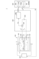
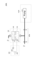
- FIG. 1 is a block diagram of a particle measuring device 1R using the electrical sensing zone method.
- the particle measuring device 1R includes a pore device 100R, a measuring instrument 200R, and a processing device 300.
- the inside of the pore device 100R is filled with an electrolyte solution 2 containing particles 4 to be detected.
- the inside of the pore device 100R is separated into two spaces by a pore chip 102, and electrodes 106 and 108 are provided in the two spaces.
- electrodes 106 and 108 are provided in the two spaces.
- the measuring device 200R generates a potential difference between the electrode pair 106, 108, and acquires information that correlates with the resistance value Rp between the electrode pair.
- the measuring device 200R includes a transimpedance amplifier 210, a voltage source 220, and a digitizer 230.
- the voltage source 220 generates a potential difference Vb between the electrode pair 106, 108. This potential difference Vb is the driving source for electrophoresis, and also serves as a bias signal for measuring the resistance value Rp.
- Is Vb/Rp...(1)
- the transimpedance amplifier 210 converts the minute current Is into a voltage signal Vs.
- Vs -r ⁇ Is...(2)
- equation (3) is obtained.
- Vs -Vb ⁇ r/Rp...(3)
- the digitizer 230 converts the voltage signal Vs into digital data Ds. In this manner, the measuring device 200R can obtain a voltage signal Vs that is inversely proportional to the resistance value Rp of the pore 104.
- the processing device 300 processes the digital data Ds and analyzes the number and particle size distribution of the particles 4 contained in the electrolyte 2.
- polarity reversal changes the chemical state around the electrode.
- the electrode-solution voltage-current curve measured by cyclic voltammetry generally has hysteresis, and the same current state may not be obtained even if the same voltage is applied.
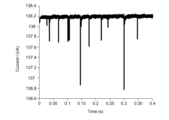
- the controller 302 may detect the clogged state ⁇ 2 based on the AC component (pulse current) of the current signal I. As shown in FIG. 4, in the normal state ⁇ 1, a pulse current is observed every time a particle passes through. In contrast, in the precursor state ⁇ 2a, the occurrence of the pulse current is more frequent than in the normal state ⁇ 1. In the completely clogged state ⁇ 2b, the occurrence frequency of the pulse current approaches zero. Therefore, the controller 302 can detect the precursor state ⁇ 2a or the completely clogged state ⁇ 2b based on the occurrence frequency of the pulse current.
- the controller 302 may detect the clogging state ⁇ 2 by utilizing characteristic changes in both the pulse current and the base current, thereby further improving the detection accuracy.
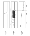
- FIG. 5 is a diagram explaining the operation of the pore device 100 particle measuring device 1 in FIG. 3.
- the controller 302 detects the precursor state ⁇ 2a.
- the particle measuring device 1 Before time t0 , the particle measuring device 1 operates normally. At time t0 , clogging begins, and pulses with short time intervals begin to be generated in the current signal I. At time t1 , the controller 302 switches the pressure control device 400 to an operating state. When the pressure control device 400 operates, the particles clogging the pores 112 are pushed back toward their original liquid chambers by the pressure of the liquid. This eliminates clogging. While the pressure control device 400 is operating, the particle measuring process by the data processing unit 304 is suspended.
- the controller 302 determines that the clogging has been eliminated at time t2 , it stops the pressure control device 400. Then, at time t3 , it restarts the particle measurement process by the data processing unit 304.
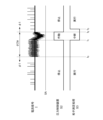
- the controller 302 acquires the instantaneous value Iac of the AC component of the current signal and the instantaneous value Idc of the DC component. It then calculates the moving average value Iac_rms of the AC component Iac over the most recent specified interval, and the moving average value Idc_rms of the DC component Idc over the specified interval.
- the controller 302 evaluates two relationships.
- a and B are parameters having predetermined values, A ⁇ 1 and B ⁇ 1.
- the controller 302 may record the pressure information (pressure value or state of the pressure control device) in a file in association with the waveform data WAVE. During analysis after measurement, the section in which the clogging was removed can be determined based on the pressure information recorded in this file. The current signal obtained in this section may then be treated as invalid data.
- pressure information pressure value or state of the pressure control device
- FIG. 7 is a block diagram of a measuring device 200A according to one embodiment.
- the measuring device 200A includes a transimpedance amplifier 210, a voltage source 220, and a digitizer 230.
- the voltage source 220 corresponds to the voltage source 202 described above.
- the transimpedance amplifier 210 corresponds to the current detection circuit 204 described above.
- the digitizer 230 corresponds to the waveform capture module 206 described above.
- the transimpedance amplifier 210 includes an operational amplifier OA1 and a resistor R1.
- the inverting input terminal of the operational amplifier OA1 is connected to the first electrode E1, and the non-inverting input terminal is grounded.
- the resistor R1 is connected between the inverting input terminal and the output terminal of the operational amplifier OA1.
- the voltage source 220 applies a voltage V to the first electrode E1. Due to the virtual grounding of the operational amplifier OA1, the potential of the inverting input terminal, i.e., the first electrode E1, becomes ground (0 V). Therefore, the voltage V is applied between the first electrode E1 and the second electrode E2.
- the digitizer 230 includes an A/D converter 232, a memory 234, and an interface circuit 236.
- the A/D converter 232 converts the current detection signal Vcs into a digital signal at a predetermined sampling period.
- the memory 234 stores waveform data.
- the interface circuit 236 transmits the waveform data stored in the memory 234 to the processing device 300.
- FIG. 8 is a diagram showing a pressure control device 400A according to one embodiment.
- the pressure control device 400A includes a pressure source 410A and a control valve 420A.
- the pressure source 410A includes an air pressure pump 412.
- the control valve 420A includes valves V1 and V2. Because sudden pressure changes can damage the pore tip 110, it is preferable to provide a buffer air vent. The state of the control valve 420A is controlled according to a control signal S2 generated by the controller 302.
- valve V1 When the pressure control device 400A is stopped, the valve V1 is in a closed state and the valve V2 can be in a conducting state. Note that the air pressure pump 412 may be stopped while the pressure control device 400A is stopped.
- the measuring device 200 can reverse the polarity of the voltage V applied to the first electrode E1 and the second electrode E2, i.e., the direction of electrophoresis.
- the pressure control device 400 switches the direction of pressure depending on the polarity of the voltage V generated by the measuring device 200, i.e., the direction of electrophoresis. Specifically, it generates a pressure difference so as to push back the particles in the opposite direction to the movement of the particles due to electrophoresis.
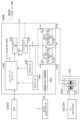
- FIG. 9 is a diagram showing a pressure control device 400B according to one embodiment.
- the pressure control device 400B mainly includes clog removal pumps 412A and 412B, valves V1 to V5, an internal power supply 402, a main pump 442, a buffer tank 444, and pressure sensors 446 and 448.
- the internal power supply 402 receives a DC power supply voltage from an external power supply, an AC adapter, and generates an internal power supply voltage that is stabilized at a predetermined voltage level by stepping up or stepping down the voltage.
- the clog removal pump 412A draws in or expels air through port A.
- the clog removal pump 412B draws in or expels air through port B.
- Controller 430 receives control signals from an external DSP (Digital Signal Processor) 4.
- DSP 4 can be part of processing device 300.
- controller 430 controls the states of valves V1 to V5, clog removal pumps 412A and 412B, and main pump 442, and switches the operating mode of pressure control device 400B.
- controller 430 controls main pump 442 based on the outputs of pressure sensors 446 and 448 so that the pressure in buffer tank 444 is constant.
- the first and second modes are modes related to removing clogging as described above.
- Valves V1, V3, and V4 are closed (off), V5 is open (on), and V2 is redundant (DC: Don't care).
- the air pressure pump 412 and the clog removal pump 412B are stopped, and the clog removal pump 412A is in operation.
- pressure is controlled via port A to remove clogging of the pore device 100.
- Valves V1, V2, and V5 are closed (off), V3 is open (on), and V4 is DC.
- the main pump 442 and the unclog pump 412A are stopped, and the unclog pump 412B is operating.
- pressure is controlled via port B to unclog the pore device 100.
- Valve V1 is closed (off), V3 and V5 are open (on), and V2 and V4 are redundant (DC: Don't care) and can be either open or closed.
- the main pump 442 and the clog removal pumps 412A and 412B are stopped.
- the third mode can be selected in the standby state when replacing the pore device 100.
- Valve V1 is closed (off), and valves V2 to V5 are redundant (DC: Don't care).
- the main pump 442 is in an operating state, and the clogging removal pumps 412A and 412B are in a stopped state.
- pressure can be accumulated in the buffer tank 444.
- the particles are driven by electrophoresis, but the application of this disclosure is not limited to this, and the present disclosure can also be applied to a driving method that uses a concentration gradient to diffuse into a liquid, or a driving method that uses a pressure difference.
- 1...particle measuring device 2...electrolyte, 4...particles, 100...pore device, 110...pore tip, 112...pore, 120...chip case, 122...first liquid chamber, 124...second liquid chamber, E1...first electrode, E2...second electrode, 200...measuring instrument, 202...voltage source, 204...current detection circuit, 206...waveform capture module, 210...transimpedance amplifier, 220...voltage source, 230...digitizer, 232...A/D converter inverter, 234...memory, 236...interface circuit, 300...processing device, 302...controller, 304...data processing unit, V1, V2, V3, V4, V5...valves, 400...pressure control device, 410...pressure source, 412...pneumatic pump, 412A, 412B...clogging removal pump, 420...control valve, 430...controller, 442...main pump, 444...buffer tank, 446, 448...pressure sensor.
Landscapes
- Chemical & Material Sciences (AREA)
- Dispersion Chemistry (AREA)
- Physics & Mathematics (AREA)
- Health & Medical Sciences (AREA)
- Life Sciences & Earth Sciences (AREA)
- Analytical Chemistry (AREA)
- Biochemistry (AREA)
- General Health & Medical Sciences (AREA)
- General Physics & Mathematics (AREA)
- Immunology (AREA)
- Pathology (AREA)
- Investigating Or Analyzing Materials By The Use Of Electric Means (AREA)
Abstract
Description
Is=Vb/Rp …(1)
Vs=-r×Is …(2)
式(1)を式(2)に代入すると、式(3)が得られる。
Vs=-Vb×r/Rp …(3)
デジタイザ230は、電圧信号VsをデジタルデータDsに変換する。このように測定器200Rにより、細孔104の抵抗値Rpに反比例する電圧信号Vsを得ることができる。処理装置300は、デジタルデータDsを処理し、電解液2に含まれる粒子4の個数や粒径分布などを解析する。
本開示のいくつかの例示的な実施形態の概要を説明する。この概要は、後述する詳細な説明の前置きとして、実施形態の基本的な理解を目的として、1つまたは複数の実施形態のいくつかの概念を簡略化して説明するものであり、発明あるいは開示の広さを限定するものではない。この概要は、考えられるすべての実施形態の包括的な概要ではなく、すべての実施形態の重要な要素を特定することも、一部またはすべての態様の範囲を線引きすることも意図していない。便宜上、「一実施形態」は、本明細書に開示するひとつの実施形態(実施例や変形例)または複数の実施形態(実施例や変形例)を指すものとして用いる場合がある。
|Iac_rms-Iac|>Iac_rms×A …(1)
である関係式(1)を評価し、当該関係式(1)が成り立つとき、圧力制御装置を動作状態としてもよい。
|Idc_rms-Idc|>Idc_rms×B …(2)
である関係式(2)を評価し、当該関係式(1)または(2)が成り立つとき、圧力制御装置を動作状態としてもよい。
以下、好適な実施の形態について図面を参照しながら説明する。各図面に示される同一または同等の構成要素、部材、処理には、同一の符号を付するものとし、適宜重複した説明は省略する。また、実施の形態は、発明を限定するものではなく例示であって、実施の形態に記述されるすべての特徴やその組み合わせは、必ずしも発明の本質的なものであるとは限らない。
|Iac_rms-Iac|>Iac_rms×A …(1)
|Idc_rms-Idc|>Idc_rms×B …(2)
A,BはA<1,B<1である所定値を有するパラメータである。
Vcs=-I×R1
となり、イオン電流Iに比例した電圧となる。したがって、イオン電流Iは、
I=Vcs/R1
として求めることができる。
バルブV1,V3,V4が閉状態(オフ)、V5が開状態(オン)、V2は冗長(DC:Don't care)である。空気圧ポンプ412、目詰まり除去ポンプ412Bが停止状態とされ、目詰まり除去ポンプ412Aが動作状態とされる。第1モードでは、ポートAを介して圧力を制御し、ポアデバイス100の目詰まり解消を行うことができる。
バルブV1,V2,V5が閉状態(オフ)、V3が開状態(オン)、V4はDCである。メインポンプ442、目詰まり除去ポンプ412Aが停止状態とされ、目詰まり除去ポンプ412Bが動作状態とされる。第2モードでは、ポートBを介して圧力を制御し、ポアデバイス100の目詰まり解消を行うことができる。
バルブV1が閉状態(オフ)、V3,V5が開状態(オン)、V2,V4は開、閉を問わない冗長(DC:Don't care)である。メインポンプ442、目詰まり除去ポンプ412A,412Bが停止状態とされる。ポアデバイス100の交換を行う際の待機状態において第3モードを選択することができる。
バルブV1が閉状態(オフ)、V2~V5は冗長(DC:Don't care)である。メインポンプ442が動作状態とされ、目詰まり除去ポンプ412A,412Bが停止状態とされる。第4モードでは、バッファタンク444に蓄圧することができる。
バルブV1,V2,V5が開状態(オン)、V3,V4は閉状態(オフ)である。メインポンプ442および目詰まり除去ポンプ412A,412Bが停止状態とされる。第5モードは、第4モードにおいてバッファタンク444に蓄圧した後に選択することができ、バッファタンク444の圧力を利用して、ポートA経由でポアデバイス100に圧力を印加することができる。なお、第5モードにおいて空気圧ポンプ412は動作させておいてもよい。
バルブV1,V3,V4が開状態(オン)、V2,V5は閉状態(オフ)である。メインポンプ442および目詰まり除去ポンプ412A,412Bが停止状態とされる。第6モードは、第4モードにおいてバッファタンク444に蓄圧した後に選択することができ、バッファタンク444の圧力を利用して、ポートB経由でポアデバイス100に圧力を印加することができる。
Claims (7)
- ポアデバイスとともに使用される微粒子測定装置であって、
前記ポアデバイスは、細孔を有する隔壁により隔てられた第1液室および第2液室を有し、
前記微粒子測定装置は、
前記第1液室に設けられた第1電極と前記第2液室に設けられた第2電極の間に流れる電流信号を測定する測定器と、
動作状態において、前記第1液室と前記第2液室に圧力差を発生させる圧力制御装置と、
前記電流信号にもとづいて、前記ポアデバイスの目詰まりを検出可能であり、前記目詰まりを検出すると前記圧力制御装置を前記動作状態とするコントローラと、
を備えることを特徴とする微粒子測定装置。 - 前記コントローラは、
前記電流信号の交流成分の瞬時値Iacと、前記電流信号の直流成分の瞬時値Idcと、を取得し、
前記交流成分の所定区間にわたる移動平均値Iac_rmsと、前記直流成分の前記所定区間にわたる移動平均値Idc_rmsと、を計算し、Aを1より小さいパラメータとして、
|Iac_rms-Iac|>Iac_rms×A …(1)
である関係式(1)を評価し、関係式(1)が成り立つとき、前記圧力制御装置を前記動作状態とすることを特徴とする請求項1に記載の微粒子測定装置。 - 前記コントローラは、Bを1より小さいパラメータとして、
|Idc_rms-Idc|>Idc_rms×B …(2)
である関係式(2)を評価し、関係式(1)または(2)が成り立つとき、前記圧力制御装置を前記動作状態とすることを特徴とする請求項2に記載の微粒子測定装置。 - 前記コントローラは、前記圧力制御装置を継続して前記動作状態とした回数をカウントし、前記回数が所定のしきい値を超えると、所定のエラー処理を実行することを特徴とする請求項2または3に記載の微粒子測定装置。
- 前記コントローラは、前記圧力制御装置を前記動作状態としている間、フラグをアサートすることを特徴とする請求項1から3のいずれかに記載の微粒子測定装置。
- 前記コントローラは、圧力情報を前記電流信号の波形データと対応付けてファイルに保存することを特徴とする請求項1から3のいずれかに記載の微粒子測定装置。
- 前記測定器は、
前記電流信号を電圧信号に変換するトランスインピーダンスアンプと、
前記トランスインピーダンスアンプの出力をデジタル信号に変換するデジタイザと、
を備えることを特徴とする請求項1から3のいずれかに記載の微粒子測定装置。
Priority Applications (1)
| Application Number | Priority Date | Filing Date | Title |
|---|---|---|---|
| CN202480037593.0A CN121336100A (zh) | 2023-06-09 | 2024-05-29 | 微粒测定装置 |
Applications Claiming Priority (2)
| Application Number | Priority Date | Filing Date | Title |
|---|---|---|---|
| JP2023-095733 | 2023-06-09 | ||
| JP2023095733A JP2024176884A (ja) | 2023-06-09 | 2023-06-09 | 微粒子測定装置 |
Related Child Applications (1)
| Application Number | Title | Priority Date | Filing Date |
|---|---|---|---|
| US19/413,207 Continuation US20260092858A1 (en) | 2023-06-09 | 2025-12-09 | Microparticle measuring apparatus |
Publications (1)
| Publication Number | Publication Date |
|---|---|
| WO2024253000A1 true WO2024253000A1 (ja) | 2024-12-12 |
Family
ID=93795963
Family Applications (1)
| Application Number | Title | Priority Date | Filing Date |
|---|---|---|---|
| PCT/JP2024/019659 Pending WO2024253000A1 (ja) | 2023-06-09 | 2024-05-29 | 微粒子測定装置 |
Country Status (3)
| Country | Link |
|---|---|
| JP (1) | JP2024176884A (ja) |
| CN (1) | CN121336100A (ja) |
| WO (1) | WO2024253000A1 (ja) |
Citations (13)
| Publication number | Priority date | Publication date | Assignee | Title |
|---|---|---|---|---|
| JPS50110278U (ja) * | 1974-02-18 | 1975-09-09 | ||
| JPS5915849A (ja) * | 1982-04-28 | 1984-01-26 | ホルガ−・キ−ゼベツタ− | 赤血球の変形能力測定装置 |
| JPH05249024A (ja) * | 1992-03-04 | 1993-09-28 | Toa Medical Electronics Co Ltd | 粒子検出装置 |
| JP2005291840A (ja) * | 2004-03-31 | 2005-10-20 | Sysmex Corp | 分析装置 |
| JP2009014702A (ja) | 2007-06-06 | 2009-01-22 | Hitachi Ltd | 微粒子検出装置及び微粒子検出方法 |
| JP2014521962A (ja) * | 2011-08-02 | 2014-08-28 | アイゾン・サイエンス・リミテッド | 粒子の特性評価 |
| JP2014219313A (ja) * | 2013-05-09 | 2014-11-20 | パナソニック株式会社 | 試料導入方法 |
| JP2015037409A (ja) * | 2010-09-29 | 2015-02-26 | 株式会社日立ハイテクノロジーズ | 生体ポリマーの光学的解析装置及び方法 |
| WO2015121394A1 (en) * | 2014-02-14 | 2015-08-20 | Ecole Polytechnique Federale De Lausanne (Epfl) | Molecular sensing device |
| JP2017120257A (ja) | 2015-12-25 | 2017-07-06 | 国立大学法人大阪大学 | 分類分析方法、分類分析装置および分類分析用記憶媒体 |
| JP2020038121A (ja) * | 2018-09-04 | 2020-03-12 | 株式会社アドバンテスト | 微粒子測定システム、情報処理装置、ソフトウェアプログラム、計測装置、微粒子の測定方法 |
| JP2021156712A (ja) * | 2020-03-26 | 2021-10-07 | 株式会社アドバンテスト | 微粒子測定システム、計測装置 |
| JP2023002249A (ja) * | 2021-06-22 | 2023-01-10 | 株式会社日立製作所 | 粒子計測装置および粒子計測方法 |
-
2023
- 2023-06-09 JP JP2023095733A patent/JP2024176884A/ja active Pending
-
2024
- 2024-05-29 WO PCT/JP2024/019659 patent/WO2024253000A1/ja active Pending
- 2024-05-29 CN CN202480037593.0A patent/CN121336100A/zh active Pending
Patent Citations (13)
| Publication number | Priority date | Publication date | Assignee | Title |
|---|---|---|---|---|
| JPS50110278U (ja) * | 1974-02-18 | 1975-09-09 | ||
| JPS5915849A (ja) * | 1982-04-28 | 1984-01-26 | ホルガ−・キ−ゼベツタ− | 赤血球の変形能力測定装置 |
| JPH05249024A (ja) * | 1992-03-04 | 1993-09-28 | Toa Medical Electronics Co Ltd | 粒子検出装置 |
| JP2005291840A (ja) * | 2004-03-31 | 2005-10-20 | Sysmex Corp | 分析装置 |
| JP2009014702A (ja) | 2007-06-06 | 2009-01-22 | Hitachi Ltd | 微粒子検出装置及び微粒子検出方法 |
| JP2015037409A (ja) * | 2010-09-29 | 2015-02-26 | 株式会社日立ハイテクノロジーズ | 生体ポリマーの光学的解析装置及び方法 |
| JP2014521962A (ja) * | 2011-08-02 | 2014-08-28 | アイゾン・サイエンス・リミテッド | 粒子の特性評価 |
| JP2014219313A (ja) * | 2013-05-09 | 2014-11-20 | パナソニック株式会社 | 試料導入方法 |
| WO2015121394A1 (en) * | 2014-02-14 | 2015-08-20 | Ecole Polytechnique Federale De Lausanne (Epfl) | Molecular sensing device |
| JP2017120257A (ja) | 2015-12-25 | 2017-07-06 | 国立大学法人大阪大学 | 分類分析方法、分類分析装置および分類分析用記憶媒体 |
| JP2020038121A (ja) * | 2018-09-04 | 2020-03-12 | 株式会社アドバンテスト | 微粒子測定システム、情報処理装置、ソフトウェアプログラム、計測装置、微粒子の測定方法 |
| JP2021156712A (ja) * | 2020-03-26 | 2021-10-07 | 株式会社アドバンテスト | 微粒子測定システム、計測装置 |
| JP2023002249A (ja) * | 2021-06-22 | 2023-01-10 | 株式会社日立製作所 | 粒子計測装置および粒子計測方法 |
Also Published As
| Publication number | Publication date |
|---|---|
| JP2024176884A (ja) | 2024-12-19 |
| CN121336100A (zh) | 2026-01-13 |
Similar Documents
| Publication | Publication Date | Title |
|---|---|---|
| US7297241B2 (en) | Method and a device for monitoring a medical microsample in the flow measuring cell of an analyzer | |
| RU2465812C2 (ru) | Система детектирования аномального выходного сигнала для биосенсора | |
| CN104296953B (zh) | 一种微孔堵孔检测方法和系统、血液细胞分析仪 | |
| CN104697917B (zh) | 基于多特征结合的电阻抗测量系统异常检测方法和系统 | |
| CN114441414B (zh) | 一种堵孔判断方法和样本分析仪 | |
| CN112730202B (zh) | 血球分析仪的阻抗法检测系统和识别阻抗通道堵孔的方法 | |
| AU2013257756A1 (en) | Method for controlling the size of solid-state nanopores | |
| CN101629925A (zh) | 用于测量纯或超纯液体的电导率的方法和设备 | |
| CN112639455B (zh) | 电解质测定装置 | |
| US20220155278A1 (en) | Small particle measurement system | |
| CN101246113B (zh) | 一种对血红蛋白测试结果的监测方法 | |
| JP5106306B2 (ja) | 電気化学的測定装置を診断する方法 | |
| WO2024253000A1 (ja) | 微粒子測定装置 | |
| JP2001305041A (ja) | 粒子信号処理装置およびそれを用いた粒子測定装置 | |
| WO2024252999A1 (ja) | 微粒子測定装置および微粒子測定方法 | |
| US20080314130A1 (en) | Detection and Subsequent Removal of an Aperture Blockage | |
| US20260092858A1 (en) | Microparticle measuring apparatus | |
| CN109298033B (zh) | 一种电化学气体传感器及其诊断方法 | |
| US20260092857A1 (en) | Microparticle measuring apparatus | |
| CN113218845B (zh) | 一种样本分析仪及其计数异常的检测方法 | |
| CN100454017C (zh) | 用于监控参考半电池的方法和设备 | |
| CN118901005A (zh) | 分析装置及状态检测方法 | |
| US20260049923A1 (en) | Microparticle measuring apparatus | |
| CN115556586A (zh) | 电池模组电量估计装置 | |
| WO2024202876A1 (ja) | 微粒子測定装置および微粒子測定方法 |
Legal Events
| Date | Code | Title | Description |
|---|---|---|---|
| 121 | Ep: the epo has been informed by wipo that ep was designated in this application |
Ref document number: 24819231 Country of ref document: EP Kind code of ref document: A1 |
|
| WWE | Wipo information: entry into national phase |
Ref document number: CN2024800375930 Country of ref document: CN |
|
| WWE | Wipo information: entry into national phase |
Ref document number: 2024819231 Country of ref document: EP |
|
| NENP | Non-entry into the national phase |
Ref country code: DE |
|
| ENP | Entry into the national phase |
Ref document number: 2024819231 Country of ref document: EP Effective date: 20260109 |
|
| ENP | Entry into the national phase |
Ref document number: 2024819231 Country of ref document: EP Effective date: 20260109 |
|
| ENP | Entry into the national phase |
Ref document number: 2024819231 Country of ref document: EP Effective date: 20260109 |
|
| ENP | Entry into the national phase |
Ref document number: 2024819231 Country of ref document: EP Effective date: 20260109 |
|
| ENP | Entry into the national phase |
Ref document number: 2024819231 Country of ref document: EP Effective date: 20260109 |