WO2024253002A1 - Automatic parking system - Google Patents
Automatic parking system Download PDFInfo
- Publication number
- WO2024253002A1 WO2024253002A1 PCT/JP2024/019716 JP2024019716W WO2024253002A1 WO 2024253002 A1 WO2024253002 A1 WO 2024253002A1 JP 2024019716 W JP2024019716 W JP 2024019716W WO 2024253002 A1 WO2024253002 A1 WO 2024253002A1
- Authority
- WO
- WIPO (PCT)
- Prior art keywords
- point
- parking
- vehicle
- route
- setting unit
- Prior art date
- Legal status (The legal status is an assumption and is not a legal conclusion. Google has not performed a legal analysis and makes no representation as to the accuracy of the status listed.)
- Ceased
Links
Images



Classifications
-
- B—PERFORMING OPERATIONS; TRANSPORTING
- B60—VEHICLES IN GENERAL
- B60W—CONJOINT CONTROL OF VEHICLE SUB-UNITS OF DIFFERENT TYPE OR DIFFERENT FUNCTION; CONTROL SYSTEMS SPECIALLY ADAPTED FOR HYBRID VEHICLES; ROAD VEHICLE DRIVE CONTROL SYSTEMS FOR PURPOSES NOT RELATED TO THE CONTROL OF A PARTICULAR SUB-UNIT
- B60W30/00—Purposes of road vehicle drive control systems not related to the control of a particular sub-unit, e.g. of systems using conjoint control of vehicle sub-units
- B60W30/06—Automatic manoeuvring for parking
-
- B—PERFORMING OPERATIONS; TRANSPORTING
- B60—VEHICLES IN GENERAL
- B60W—CONJOINT CONTROL OF VEHICLE SUB-UNITS OF DIFFERENT TYPE OR DIFFERENT FUNCTION; CONTROL SYSTEMS SPECIALLY ADAPTED FOR HYBRID VEHICLES; ROAD VEHICLE DRIVE CONTROL SYSTEMS FOR PURPOSES NOT RELATED TO THE CONTROL OF A PARTICULAR SUB-UNIT
- B60W50/00—Details of control systems for road vehicle drive control not related to the control of a particular sub-unit, e.g. process diagnostic or vehicle driver interfaces
-
- B—PERFORMING OPERATIONS; TRANSPORTING
- B60—VEHICLES IN GENERAL
- B60W—CONJOINT CONTROL OF VEHICLE SUB-UNITS OF DIFFERENT TYPE OR DIFFERENT FUNCTION; CONTROL SYSTEMS SPECIALLY ADAPTED FOR HYBRID VEHICLES; ROAD VEHICLE DRIVE CONTROL SYSTEMS FOR PURPOSES NOT RELATED TO THE CONTROL OF A PARTICULAR SUB-UNIT
- B60W50/00—Details of control systems for road vehicle drive control not related to the control of a particular sub-unit, e.g. process diagnostic or vehicle driver interfaces
- B60W2050/0062—Adapting control system settings
- B60W2050/0075—Automatic parameter input, automatic initialising or calibrating means
- B60W2050/0083—Setting, resetting, calibration
-
- B—PERFORMING OPERATIONS; TRANSPORTING
- B60—VEHICLES IN GENERAL
- B60W—CONJOINT CONTROL OF VEHICLE SUB-UNITS OF DIFFERENT TYPE OR DIFFERENT FUNCTION; CONTROL SYSTEMS SPECIALLY ADAPTED FOR HYBRID VEHICLES; ROAD VEHICLE DRIVE CONTROL SYSTEMS FOR PURPOSES NOT RELATED TO THE CONTROL OF A PARTICULAR SUB-UNIT
- B60W2540/00—Input parameters relating to occupants
- B60W2540/18—Steering angle
-
- B—PERFORMING OPERATIONS; TRANSPORTING
- B60—VEHICLES IN GENERAL
- B60W—CONJOINT CONTROL OF VEHICLE SUB-UNITS OF DIFFERENT TYPE OR DIFFERENT FUNCTION; CONTROL SYSTEMS SPECIALLY ADAPTED FOR HYBRID VEHICLES; ROAD VEHICLE DRIVE CONTROL SYSTEMS FOR PURPOSES NOT RELATED TO THE CONTROL OF A PARTICULAR SUB-UNIT
- B60W2556/00—Input parameters relating to data
- B60W2556/45—External transmission of data to or from the vehicle
- B60W2556/50—External transmission of data to or from the vehicle of positioning data, e.g. GPS [Global Positioning System] data
-
- B—PERFORMING OPERATIONS; TRANSPORTING
- B60—VEHICLES IN GENERAL
- B60W—CONJOINT CONTROL OF VEHICLE SUB-UNITS OF DIFFERENT TYPE OR DIFFERENT FUNCTION; CONTROL SYSTEMS SPECIALLY ADAPTED FOR HYBRID VEHICLES; ROAD VEHICLE DRIVE CONTROL SYSTEMS FOR PURPOSES NOT RELATED TO THE CONTROL OF A PARTICULAR SUB-UNIT
- B60W60/00—Drive control systems specially adapted for autonomous road vehicles
- B60W60/001—Planning or execution of driving tasks
- B60W60/0011—Planning or execution of driving tasks involving control alternatives for a single driving scenario, e.g. planning several paths to avoid obstacles
Definitions
- This disclosure relates to an automated parking system.
- an automatic parking system that stores the driving path of a vehicle when the driver parks the vehicle in a parking space as a reference path, sets a parking path along the stored reference path, and automatically drives the vehicle.
- a junction point with the reference path is determined so that the travel angle of the vehicle relative to the reference path is smaller than a predetermined angle, and the vehicle is driven.
- the vehicle may join the reference route with a large steering angle even though the travel angle of the vehicle relative to the reference route is smaller than a predetermined angle, which may cause the vehicle's driving condition to become unstable.
- the difference between the reference route and the vehicle may become large, and it may not be possible to determine a joining point where the travel angle of the vehicle relative to the reference route is smaller than a predetermined angle.
- an automatic parking system that automatically drives a vehicle and parks the vehicle.
- This automatic parking system includes a vehicle state detection unit that detects vehicle states including at least the position and steering angle of the vehicle, a reference route storage unit that stores a reference route consisting of a plurality of waypoints that are points that indicate the vehicle state when the vehicle is driven to a target point by a driver, a parking route setting unit that sets a parking route from an automatic parking start point to the target point, and a vehicle control unit that controls the vehicle to drive along the parking route, and the parking route setting unit sets the parking route using a neutral point, which is a point where the steering angle is neutral among the plurality of waypoints, as a tentative end point.
- the parking path setting unit sets the parking path with the neutral point as the temporary end point, so that the vehicle can join the reference path with the steering angle neutral, and compared to a configuration in which the joining point with the reference path is determined only by the vehicle's travel angle relative to the reference path, it is possible to prevent the vehicle's driving state from becoming unstable. Also, compared to a configuration in which the parking path is set with a waypoint where the steering angle is in either direction as the temporary end point, it is possible to easily take a course to the left or right on the parking path after reaching the temporary end point, and it is possible to prevent the direction of travel being restricted on the parking path after reaching the temporary end point.
- an automatic parking system that automatically drives a vehicle and parks the vehicle.
- the automatic parking system includes a vehicle state detection unit that detects vehicle states including at least the position and steering angle of the vehicle, a reference path storage unit that stores a reference path consisting of a plurality of waypoints that are points that indicate the vehicle state when the vehicle is driven to a target point by a driver, a parking path setting unit that sets a parking path from an automatic parking start point to the target point, and a vehicle control unit that controls the vehicle to drive along the parking path.
- the parking path setting unit When the difference between the parking path, which is set with a first waypoint that is one of the plurality of waypoints as a temporary end point, and the reference path is equal to or greater than a predetermined threshold distance, the parking path setting unit re-sets the parking path using a second waypoint that is a waypoint different from the first waypoint and located closer to the vehicle than the first waypoint as a temporary end point.
- the parking route is re-set with a second via point, which is a via point different from the first via point and is located closer to the vehicle than the first via point, as the tentative end point. This makes it easier to set a parking route that merges more quickly from the automatic parking start point to the reference route and has a smaller difference from the reference route.
- FIG. 1 is a block diagram showing a schematic configuration of an automatic parking system according to an embodiment of the present invention.
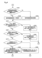
- FIG. 2 is a flowchart showing the procedure of the parking route setting process according to the present embodiment.
- FIG. 3 is a flowchart showing the procedure of the parking route setting process according to the present embodiment.
- FIG. 4 is a flowchart showing the procedure of the parking route setting process according to the present embodiment.
- FIG. 5 is a flowchart showing the procedure of the reference point selection process according to the present embodiment.
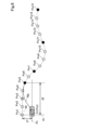
- FIG. 6 is an explanatory diagram showing an example of a reference path and a parking path.
- the vehicle condition detection unit 100 detects the vehicle condition of the vehicle M.
- the vehicle condition includes at least the position of the vehicle M and the steering angle at that position.
- the automatic parking system 10 of this embodiment is equipped with an image sensor 110 and a steering angle sensor 120 as the vehicle condition detection unit 100.
- the image sensor 110 is mounted on the vehicle M so as to capture images of the front, rear, left and right of the vehicle M, for example.
- the image sensor 110 captures images of objects and markers (hereinafter also referred to as "reference objects") present around the vehicle M, and acquires the captured images.
- the steering angle sensor 120 detects the steering angle of the steering wheels while the vehicle M is traveling.
- the automatic parking system 10 may also include, as the vehicle condition detection unit 100, various sensors such as millimeter wave radar, ultrasonic sensors, and LiDAR (Light Detection and Ranging) that detect targets around the vehicle M, a GNSS receiver that receives navigation signals from artificial satellites that make up the GNSS (Global Navigation Satellite System) to detect the current position (longitude and latitude) of the vehicle M, and a vehicle speed sensor that detects the speed of the vehicle M.
- various sensors such as millimeter wave radar, ultrasonic sensors, and LiDAR (Light Detection and Ranging) that detect targets around the vehicle M
- GNSS receiver that receives navigation signals from artificial satellites that make up the GNSS (Global Navigation Satellite System) to detect the current position (longitude and latitude) of the vehicle M
- GNSS Global Navigation Satellite System
- the reference route storage unit 200 of this embodiment is configured as an ECU including a CPU 210 and a memory 220.
- the reference route storage unit 200 stores a reference route.
- the "reference route” refers to the route traveled when the vehicle M travels a section from an arbitrary starting point to a target point (hereinafter also referred to as a "learning section") driven by the driver.
- the reference route is made up of a plurality of waypoints which are points indicating the above-mentioned vehicle state in the learning section.
- the starting point of the reference route is set to the position of the vehicle M at the time when the driver operates a button to instruct the start of a learning mode in which the reference route is stored.
- the target point is set to the position of the vehicle M at the time when the driver operates a button to instruct the end of the learning mode. If an upper limit route length that can be stored as a reference route is previously determined, the target point is set to the position of the vehicle M at the time when the route length from the starting point reaches the upper limit route length.
- the reference route storage unit 200 stores a plurality of waypoints indicating the vehicle state acquired by the vehicle state detection unit 100 as waypoint data Pw in the memory 220 each time a predetermined distance is traveled. More specifically, the reference route storage unit 200 calculates the position of the vehicle M based on the reference target by analyzing the captured image at each point acquired from the image sensor 110 each time a predetermined distance is traveled, and stores the calculated position of the vehicle M as waypoint data Pw in the memory 220. In addition, the reference route storage unit 200 acquires the steering angle at each point from the steering angle sensor 120 each time a predetermined distance is traveled, and stores the acquired steering angle in the memory 220 as waypoint data Pw.
- the data indicating the waypoint that is the start point of the learning section among the waypoint data Pw includes at least the position of the start point based on the reference target and the steering angle at the start point.
- data indicating other way points following the starting point includes at least the position of each way point relative to the starting point and the steering angle at each way point.
- the parking route setting unit 300 of this embodiment is configured as an ECU equipped with a CPU 310 and a memory 320.
- the parking route setting unit 300 sets a parking route from the automatic parking start point to the target point of the above-mentioned learning section.
- the automatic parking start point may be any point that does not coincide with the start point of the above-mentioned reference route.
- the parking route setting unit 300 also stores parking route candidates that are set as parking route candidates. In FIG. 1, four parking route candidates RT1 to RT4 are stored in the memory 320, but the number of parking route candidates stored in the memory 220 is not limited to four. The specific steps of the parking route setting method will be described later.
- the vehicle control unit 400 of this embodiment is configured as an ECU equipped with a CPU 410 and a memory 420.
- the vehicle control unit 400 controls the vehicle operation device 500 so that the vehicle M travels according to the operation of the accelerator pedal, brake pedal, or steering wheel by the driver, or according to a parking route set by the parking route setting unit 300.
- the vehicle operation device 500 includes a drive device 510, a brake device 520, and a steering device 530.
- the drive device 510 outputs a drive force for driving the vehicle M.
- the drive device 51 is, for example, an internal combustion engine, a motor, etc.
- the drive device 510 is electrically connected to the vehicle control unit 400, and the drive force is controlled by a control signal transmitted from the vehicle control unit 400.
- the brake device 520 outputs a braking force for braking the vehicle M.
- the brake device 520 is electrically connected to the vehicle control unit 400, and the braking force is controlled by a control signal transmitted from the vehicle control unit 400.
- the steering device 530 outputs a steering force for steering the vehicle M.
- the steering device 530 is, for example, a power steering device, etc.
- the steering device 530 is electrically connected to the vehicle control unit 400, and the steering force is controlled by a control signal transmitted from the vehicle control unit 400.
- A-2. Parking route setting process The automatic parking system 10 of this embodiment executes the parking route setting process shown in Figures 2 to 4 to set a parking route.
- the parking route is set to merge with the reference route from the current position of the vehicle M and reach the learned target point.
- the parking route setting process is started when the driver instructs the start of the parking route setting process by operating a button, for example.
- the automatic parking system 10 controls the vehicle operation device 500 to drive the vehicle M along the set parking route.
- step S110 shown in FIG. 2 the parking route setting unit 300 acquires the waypoint data Pw from the reference route memory unit 200.
- step S120 the parking route planning unit 300 acquires captured images of the surroundings of the vehicle M from the vehicle state detection unit 100.
- the parking route setting unit 300 uses the acquired way point data Pw and the captured image to identify the position of the start point of the reference route. More specifically, the parking route setting unit 300 identifies a reference target in the acquired captured image, and identifies the position of the start point by comparing it with the position of the start point indicated by the way point data Pw, which is based on the reference target. Note that the identification of the reference target in the captured image can be achieved by performing well-known image processing such as pattern matching.
- step S140 the parking route setting unit 300 executes a reference point selection process to select a reference point from the multiple via points indicated by the acquired via point data Pw.
- the "reference point” refers to a via point among the multiple via points that is to be preferentially used to attempt to merge from the current position to the reference route.
- FIG. 6 a reference route Wr consisting of via points Pw1 to Pw15 is shown.
- the via points Pw5 to Pw15 are shown by black circles, and the other via points are shown by white circles.
- the via point Pw3 shown with hatching will be described later.
- step S142 shown in FIG. 5 the parking path setting unit 300 selects a via point with a neutral steering angle (hereinafter also referred to as a "neutral point") from among the multiple via points as a reference point. Note that in the straight line portion of the reference path, the reference points are selected at predetermined intervals. In the example shown in FIG. 6, via points Pw7 and Pw11 are selected as reference points for neutral points.
- step S144 the parking path setting unit 300 determines whether the distance between the vehicle M and the reference path is equal to or greater than a predetermined threshold. As shown in FIG. 6, in this embodiment, the parking path setting unit 300 calculates, as the distance between the vehicle M and the reference path, the distance d1 along the rear wheel axis Ar from the vehicle reference point Cr, which is the intersection of the central axis Ac of the vehicle M in the width direction and the rear wheel axis Ar of the vehicle M, to the reference path.
- step S146 the parking route setting unit 300 selects a way point that is equal to or greater than a predetermined allowable distance from the vehicle M as a reference point.
- the "allowable distance” is a distance between the vehicle M and the way point that allows the vehicle M to merge with the reference route without abrupt steering, and is specified and set in advance by performing simulations or the like.
- FIG. 6 shows an example in which the distance d1 is determined to be equal to or greater than the threshold.
- the parking route setting unit 300 selects a way point that is equal to or greater than the allowable distance from the vehicle reference point Cr along the central axis Ac as a reference point.
- FIG. 6 shows an example in which via point Pw5 is selected as the reference point because the distance d2 along the central axis Ac from the vehicle reference point Cr is equal to or greater than the allowable distance.
- via point Pw3 which is located on a straight path and shown hatched, has a neutral steering angle, but is not selected as the reference point because the distance along the central axis Ac from the vehicle reference point Cr is less than the allowable distance.
- Via point Pw3 corresponds to the "nearest neutral point" in this disclosure.
- step S144 determines that the distance between the vehicle M and the reference route is less than the threshold (step S144: No). If it is determined that the distance between the vehicle M and the reference route is less than the threshold (step S144: No), the parking route setting unit 300 does not execute step S146 and proceeds to step S148.
- step S148 the parking route setting unit 300 selects, from among the multiple via points, the via point located at the end of the reference route as the reference point.
- via point Pw15 located at the end of the reference route Wr is selected as the reference point. This completes the reference point selection process.
- step S150 shown in FIG. 2 the parking route setting unit 300 sets the automatic parking start point of the vehicle M as the starting point and the first reference point as the tentative end point.
- the automatic parking start point Pst which is the vehicle reference point Cr at the start of the parking route generation process, is set as the starting point
- the intermediate point Pw5 is set as the tentative end point.
- step S160 the parking route setting unit 300 sets a one-circle route from the set start point to the tentative end point.
- a one-circle route means a route in which a start point and a tentative end point are connected by a single arc.
- the one-circle route is formed as an arc that is tangent to the reference route with the tentative end point as a tangent point.
- the end point of the set one-circle route does not necessarily have to coincide with the tentative end point, and the one-circle route may be a route up to the vicinity of the tentative end point. Since a one-circle route does not require a change in steering angle midway along the route, it is possible to prevent the running state of the vehicle M from becoming unstable, compared to a two-circle route described below.
- step S170 shown in FIG. 3 the parking path setting unit 300 determines whether the radius of curvature of the set one-circle path is less than a predetermined threshold value. If it is determined that the radius of curvature is less than the threshold value (step S170: Yes), in step S180, the parking path setting unit 300 sets a two-circle path from the set start point to the tentative end point.
- the two-circle path means a path in which the start point and the tentative end point are connected by two arcs.
- the arc that connects to the tentative end point is formed as an arc that is tangent to the reference path with the tentative end point as the tangent point.
- FIG. 6 shows a parking path Wp that is set as a two-circle path connecting the automatic parking start point Pst, which is the starting point, and the via point Pw5, which is the tentative end point.
- the parking path Wp is an S-shaped path formed by two mutually circumscribing circular arcs.
- step S190 shown in FIG. 3 the parking route setting unit 300 selects, as a parking route candidate, the route between the set one-circle route and the set two-circle route, whose end point is closer to the set tentative end point.
- step S192 the parking route setting unit 300 selects the circular route as a candidate parking route.
- step S200 the parking route setting unit 300 determines whether the distance between the tentative end point and the end point of the parking route candidate is less than a predetermined threshold. If it is determined that the distance between the tentative end point and the end point of the parking route candidate is less than the threshold (step S200: Yes), in step S210, the parking route setting unit 300 adopts the parking route candidate selected in the above-mentioned step S190 as the parking route.
- step S220 the parking route setting unit 300 determines whether route setting has been completed up to the last reference point on the adopted parking route.
- step S220 If it is determined that route setting has been completed up to the last reference point (step S220: Yes), the parking route setting unit 300 ends the parking route setting process.
- step S222 the parking route setting unit 300 sets the end point of the adopted parking route as the new start point and the next reference point as the new tentative end point.
- the next reference point is the waypoint Pw7.
- the parking route setting unit 300 then executes the above-mentioned step S160 again.
- step S230 shown in FIG. 4 the parking route setting unit 300 determines whether the difference between the parking route candidate and the reference route is less than the threshold.
- the reference route can be said to be a route that reflects the driver's intention for parking the vehicle M, such as avoiding obstacles such as flower beds. If automatic parking is performed by adopting a parking route that is significantly different from such a route, there is a risk of a problem such as contacting an obstacle contrary to the driver's intention. In order to avoid such a problem, the parking route setting unit 300 performs the determination in step S230.
- the parking route setting unit 300 calculates the distance between the reference route based on each point along a direction perpendicular to the parking route candidate at multiple points located at predetermined intervals on the parking route candidate, and determines the average value of such distances as the difference between the parking route candidate and the reference route.
- step S240 the parking route setting unit 300 temporarily stores the parking route candidate in the memory 320.
- step S242 the parking route setting unit 300 rejects the parking route candidate and does not temporarily store it in the memory 320.
- step S250 the parking route setting unit 300 determines whether the route has already been set as a temporary end point for the via point immediately preceding the via point that is set as the temporary end point.
- the "previous via point” refers to another via point adjacent to the via point that is set as the temporary end point and is located closer to the vehicle M.
- the via point Pw4 corresponds to the "previous via point" of the via point Pw5.
- step S252 the parking route setting unit 300 does not change the starting point and sets the previous via point as a new tentative end point.
- the parking route setting unit 300 then executes the above-mentioned step S160 again. In this way, even if the parking route setting unit 300 sets the reference point as the tentative end point and attempts to set a route, if the distance between the tentative end point and the end point of the parking route candidate is equal to or greater than the threshold value (step S200: No), the parking route setting unit 300 attempts to set a route by going back one via point at a time. In the example shown in FIG.
- the parking route setting unit 300 attempts to set a route using the via point Pw5, which is the reference point, as a tentative end point, and then attempts to set the via points Pw4, Pw3, Pw2, and Pw1 in that order as tentative end points until a parking route candidate is set in which the distance between the tentative end point and the end point of the parking route candidate is less than the threshold (step S200: Yes).
- step S200 Yes
- the parking route setting unit 300 attempts to set a route using the via point Pw5, which is the reference point, as a tentative end point, and then attempts to set the via points Pw4, Pw3, Pw2, and Pw1 in that order as tentative end points until a parking route candidate is set in which the distance between the tentative end point and the end point of the parking route candidate is less than the threshold.
- step S260 the parking route setting unit 300 determines whether the route has already been set with the last reference point as the tentative end point. In other words, in this step, the parking route setting unit 300 determines whether the route has already been set for all via points.
- step S262 the parking route setting unit 300 does not change the starting point and sets the next reference point as a new tentative end point. After that, the parking route setting unit 300 executes the above-mentioned step S160 again. In the example shown in FIG. 6, the parking route setting unit 300 attempts to set a route with via point Pw1 as the tentative end point, and then attempts to set a route with via point Pw7, which is the reference point next to via point Pw5, as the new tentative end point.
- the parking route setting unit 300 attempts to set the route by setting the intermediate points Pw6, Pw11, Pw10, Pw9, Pw8, Pw15, Pw14, Pw13, and Pw12 as the tentative end point in this order until a parking route candidate is set in which the distance between the tentative end point and the end point of the parking route candidate is less than the threshold (step S200: Yes).
- step S260 if it is determined that the route has already been set with the last reference point as the temporary end point (step S260: Yes), in other words, if it is determined that route setting has been attempted for all intermediate points, in step S270, the parking route setting unit 300 determines whether there are any parking route candidates temporarily stored in the memory 320.
- step S280 the parking route setting unit 300 adopts the parking route candidate with the shortest distance between the end point of the parking route candidate and the tentative end point as the parking route. After that, the parking route setting unit 300 executes the above-mentioned step S220 again.
- step S282 the parking route setting unit 300 determines that there are no available parking routes and ends the parking route setting process.
- the parking path setting unit 300 sets a parking path with the neutral point as a temporary end point, so that the vehicle can merge with the reference path with a neutral steering angle, and this can prevent the vehicle M's driving state from becoming unstable, compared to a configuration in which the merging point with the reference path is determined only by the travel angle of the vehicle M relative to the reference path. Also, compared to a configuration in which a parking path is set with a waypoint where the steering angle is inclined to either the left or right as a temporary end point, the vehicle can easily take a course to the left or right on the parking path after reaching the temporary end point. This can prevent the travel direction from being restricted on the parking path after reaching the temporary end point.
- the parking route is re-set with a second via point, which is a via point different from the first via point and is located closer to the vehicle M than the first via point, as the tentative end point. This makes it easier to set a parking route that merges more quickly from the automatic parking start point to the reference route and has a smaller difference from the reference route.
- the parking route is not set with the nearest neutral point as the tentative end point, but instead, a via point among multiple via points whose distance from vehicle M is equal to or greater than the allowable distance is set as the tentative end point, thereby preventing abrupt steering when joining the reference route from the automatic parking start point Pst.
- step S250 when the parking route setting unit 300 has not yet generated a route with the previous via point as a tentative end point in step S250 of the parking route setting process (step S250: No), the parking route setting unit 300 sets the previous via point as a new tentative end point (step S252), but the present disclosure is not limited thereto. In such a case, the parking route setting unit 300 may set a via point two or more before as a new tentative end point.
- the automatic parking system 10 of this form also achieves the same effect as the above embodiment.
- since a via point closer to the vehicle M than the previous via point is set as a tentative end point, it is easier to set a parking route that merges more quickly from the automatic parking start point to the reference route.
- step S250 if the parking route setting unit 300 has already generated a route with the previous via point as a tentative end point in step S250 of the parking route setting process (step S250: Yes), the parking route setting unit 300 does not attempt to generate a route by setting the previous via point as a new tentative end point, but the present disclosure is not limited to this. Even in such a case, the parking route setting unit 300 may attempt to generate a route by setting the previous via point as a new tentative end point.
- step S3 if the parking route setting unit 300 has not yet generated a route with the last reference point as the tentative end point in step S260 of the parking route setting process (step S260: No), the parking route setting unit 300 sets the next reference point as a new tentative end point (step S262), but the present disclosure is not limited to this. In such a case, the parking route setting unit 300 may set a waypoint that is not a reference point as the tentative end point.
- the parking path setting unit 300 selects the neutral point as the reference point in step S142 of the reference point selection process, but the present disclosure is not limited to this.
- the parking path setting unit 300 does not have to select the neutral point as the reference point.
- a second via point which is a via point different from the first via point and is located closer to the vehicle M than the first via point, as a temporary end point, it is possible to easily set a parking path that merges more quickly from the automatic parking start point to the reference path and has a small difference from the reference path.
- step S144: No when the distance between vehicle M and the reference route is less than the threshold value in step S144 of the reference point selection process (step S144: No), the parking route setting unit 300 does not select a way point that is more than the allowable distance away from vehicle M as a reference point, but the present disclosure is not limited to this. Even when the distance between vehicle M and the reference route is more than the threshold value (step S144: No), the parking route setting unit 300 may select a way point that is more than the allowable distance away from vehicle M as a reference point. This type of automatic parking system 10 can also suppress abrupt steering when joining the reference route from the automatic parking start point Pst.
- step S200 when the distance between the tentative end point and the parking route candidate is equal to or greater than the threshold value in step S200 of the parking route setting process (step S200: No), the parking route setting unit 300 executes the processes from step S230 to step S282, but the present disclosure is not limited thereto. In such a case, the parking route setting unit 300 does not need to execute the processes from step S230 to step S282.
- the parking route is set with the neutral point as the tentative end point, so that the vehicle M can merge with the reference route with the steering angle neutral, and the vehicle M's running state can be prevented from becoming unstable.
- the vehicle M can be prevented from being restricted in the traveling direction in the parking route after reaching the tentative end point.
- the automated parking system 10 and the method described herein may be realized by a dedicated computer provided by configuring a processor and a memory programmed to execute one or more functions embodied in a computer program.
- the automated parking system 10 and the method described herein may be realized by a dedicated computer provided by configuring a processor with one or more dedicated hardware logic circuits.
- the automated parking system 10 and the method described herein may be realized by one or more dedicated computers configured by a combination of a processor and a memory programmed to execute one or more functions and a processor configured with one or more hardware logic circuits.
- the computer program may also be stored in a computer-readable non-transient tangible recording medium as instructions executed by the computer.
- the present disclosure is not limited to the above-mentioned embodiment, and can be realized in various configurations without departing from the spirit of the present disclosure.
- the technical features in each embodiment corresponding to the technical features in the form described in the Summary of the Invention column can be appropriately replaced or combined in order to solve some or all of the above-mentioned problems or to achieve some or all of the above-mentioned effects.
- the technical feature is not described as essential in this specification, it can be appropriately deleted.
- An automatic parking system (10) for automatically driving a vehicle (M) and parking the vehicle A vehicle state detection unit (100) that detects a vehicle state including at least a position and a steering angle of the vehicle;
- a reference route storage unit (200) that stores a reference route (Wr) consisting of a plurality of waypoints (Pw1 to Pw15) that are points that indicate the vehicle state when the vehicle travels to a target point by being driven by a driver;
- a vehicle control unit (400) that controls the vehicle to travel along the parking path; Equipped with The parking path setting unit sets the parking path by setting a neutral point, which is a point where the steering angle is neutral, among the plurality of via points as a temporary end point.
- An automatic parking system that automatically drives a vehicle and parks the vehicle, a vehicle state detection unit that detects a vehicle state including at least a position and a steering angle of the vehicle; a reference route storage unit that stores a reference route including a plurality of waypoints that indicate a vehicle state when the vehicle is driven by a driver to a target point; A parking route setting unit that sets a parking route from an automatic parking start point to the target point; A vehicle control unit that controls the vehicle to travel along the parking path; Equipped with When a difference between the parking route, which is set with a first via point that is one of the plurality of via points as a tentative end point, and the reference route is equal to or greater than a predetermined threshold distance, the parking route setting unit sets the parking route again with a second via point that is a via point different from the first via point and located closer to the vehicle than the first via point as a tentative end point.
- Automatic parking system (Form 3) The automatic parking system according to aspect 2, The parking path setting unit sets the parking path so that the reference path and the parking path merge at a neutral point, which is a point where the steering angle is neutral among the plurality of via points, as a temporary end point, as the first via point.
- Automatic parking system (Form 4) The automatic parking system according to claim 2 or 3, When the parking route setting unit has already attempted to set the parking route with the second via point as a tentative end point, the parking route setting unit does not set the parking route with the second via point as a target, and sets the parking route again with another via point for which the setting of the parking route has not yet been attempted as a tentative end point. Automatic parking system.
Landscapes
- Engineering & Computer Science (AREA)
- Automation & Control Theory (AREA)
- Transportation (AREA)
- Mechanical Engineering (AREA)
- Human Computer Interaction (AREA)
- Steering Control In Accordance With Driving Conditions (AREA)
- Navigation (AREA)
Abstract
Description
本出願は、2023年6月6日に出願された日本出願番号2023-92858号に基づくもので、ここにその記載内容を援用する。 This application is based on Japanese Application No. 2023-92858, filed on June 6, 2023, the contents of which are incorporated herein by reference.
本開示は、自動駐車システムに関する。 This disclosure relates to an automated parking system.
従来、運転者の運転により駐車スペースに車両を駐車させる際の車両の走行経路を基準経路として記憶し、記憶された基準経路に沿うように駐車経路を設定し自動的に車両を走行させる自動駐車システムが知られている。このような自動駐車システムを実現する特許文献1に記載の運転者支援方法では、基準経路に対する車両の進行角度が予め定められた角度よりも小さくなるように基準経路への合流地点を決定し、車両を走行させる。
Conventionally, there is known an automatic parking system that stores the driving path of a vehicle when the driver parks the vehicle in a parking space as a reference path, sets a parking path along the stored reference path, and automatically drives the vehicle. In the driver assistance method described in
しかしながら、基準経路に対する車両の進行角度のみによって基準経路への合流地点を決定すると、基準経路に対する車両の進行角度が予め定められた角度よりも小さいものの、操舵角度が大きい状態で基準経路へ合流して、車両の走行状態が不安定になる場合が生じ得る。また、駐車支援を開始する際の車両の位置によっては基準経路と車両との差異が大きくなり、基準経路に対する車両の進行角度が予め定められた角度よりも小さくなるような合流地点を決定できないおそれがある。 However, if the joining point to the reference route is determined based only on the travel angle of the vehicle relative to the reference route, the vehicle may join the reference route with a large steering angle even though the travel angle of the vehicle relative to the reference route is smaller than a predetermined angle, which may cause the vehicle's driving condition to become unstable. In addition, depending on the position of the vehicle when parking assistance begins, the difference between the reference route and the vehicle may become large, and it may not be possible to determine a joining point where the travel angle of the vehicle relative to the reference route is smaller than a predetermined angle.
本開示は、以下の形態として実現することが可能である。 This disclosure can be realized in the following forms:
本開示の一形態によれば、車両を自動走行させて前記車両を駐車させる自動駐車システムが提供される。この自動駐車システムは、前記車両の位置および操舵角度を少なくとも含む車両状態を検出する車両状態検出部と、運転者の運転により前記車両が目標地点まで走行した際の前記車両状態を示す点である複数の経由点からなる基準経路を記憶する基準経路記憶部と、自動駐車開始地点から前記目標地点までの駐車経路を設定する駐車経路設定部と、前記駐車経路に沿って走行するように前記車両を制御する車両制御部と、を備え、前記駐車経路設定部は、前記複数の経由点のうち、前記操舵角度が中立である地点である中立地点を仮の終点として前記駐車経路を設定する。 According to one embodiment of the present disclosure, an automatic parking system is provided that automatically drives a vehicle and parks the vehicle. This automatic parking system includes a vehicle state detection unit that detects vehicle states including at least the position and steering angle of the vehicle, a reference route storage unit that stores a reference route consisting of a plurality of waypoints that are points that indicate the vehicle state when the vehicle is driven to a target point by a driver, a parking route setting unit that sets a parking route from an automatic parking start point to the target point, and a vehicle control unit that controls the vehicle to drive along the parking route, and the parking route setting unit sets the parking route using a neutral point, which is a point where the steering angle is neutral among the plurality of waypoints, as a tentative end point.
この形態の自動駐車システムによれば、駐車経路設定部は、中立地点を仮の終点として駐車経路を設定するので操舵角度が中立の状態で基準経路へ合流でき、基準経路に対する車両の進行角度のみによって基準経路への合流地点を決定する構成と比べて、車両の走行状態が不安定になることを抑制できる。また、操舵角度が左右いずれかに振れている経由点を仮の終点として駐車経路を設定する構成と比べて、仮の終点に到達した後の駐車経路において左右いずれにも進路を容易に取ることができ、仮の終点に到達した後の駐車経路において進行方向が制限されることを抑制できる。 In this form of automatic parking system, the parking path setting unit sets the parking path with the neutral point as the temporary end point, so that the vehicle can join the reference path with the steering angle neutral, and compared to a configuration in which the joining point with the reference path is determined only by the vehicle's travel angle relative to the reference path, it is possible to prevent the vehicle's driving state from becoming unstable. Also, compared to a configuration in which the parking path is set with a waypoint where the steering angle is in either direction as the temporary end point, it is possible to easily take a course to the left or right on the parking path after reaching the temporary end point, and it is possible to prevent the direction of travel being restricted on the parking path after reaching the temporary end point.
本開示の他の形態によれば、車両を自動走行させて前記車両を駐車させる自動駐車システムが提供される。この自動駐車システムは、前記車両の位置および操舵角度を少なくとも含む車両状態を検出する車両状態検出部と、運転者の運転により前記車両が目標地点まで走行した際の前記車両状態を示す点である複数の経由点からなる基準経路を記憶する基準経路記憶部と、自動駐車開始地点から前記目標地点までの駐車経路を設定する駐車経路設定部と、前記駐車経路に沿って走行するように前記車両を制御する車両制御部と、を備え、前記駐車経路設定部は、前記複数の経由点のうちの1つである第1の経由点を仮の終点として設定された前記駐車経路と、前記基準経路と、の差異が予め定められた閾値距離以上である場合に、前記複数の経由点のうち、前記第1の経由点とは異なる経由点であって、前記第1の経由点よりも前記車両に近い位置に位置する経由点である第2の経由点を仮の終点として、前記駐車経路を再度設定する。 According to another aspect of the present disclosure, an automatic parking system is provided that automatically drives a vehicle and parks the vehicle. The automatic parking system includes a vehicle state detection unit that detects vehicle states including at least the position and steering angle of the vehicle, a reference path storage unit that stores a reference path consisting of a plurality of waypoints that are points that indicate the vehicle state when the vehicle is driven to a target point by a driver, a parking path setting unit that sets a parking path from an automatic parking start point to the target point, and a vehicle control unit that controls the vehicle to drive along the parking path. When the difference between the parking path, which is set with a first waypoint that is one of the plurality of waypoints as a temporary end point, and the reference path is equal to or greater than a predetermined threshold distance, the parking path setting unit re-sets the parking path using a second waypoint that is a waypoint different from the first waypoint and located closer to the vehicle than the first waypoint as a temporary end point.
この形態の自動駐車システムによれば、第1の経由点を仮の終点として設定された駐車経路と、基準経路と、の差異が予め定められた閾値距離以上である場合に、複数の経由点のうち、第1の経由点とは異なる経由点であって、第1の経由点よりも車両に近い位置に位置する経由点である第2の経由点を仮の終点として駐車経路を再度設定するので、自動駐車開始地点から基準経路へより早く合流し、基準経路との差異が小さい駐車経路を設定しやすくできる。 In this form of automatic parking system, if the difference between the parking route set with the first via point as the tentative end point and the reference route is equal to or greater than a predetermined threshold distance, the parking route is re-set with a second via point, which is a via point different from the first via point and is located closer to the vehicle than the first via point, as the tentative end point. This makes it easier to set a parking route that merges more quickly from the automatic parking start point to the reference route and has a smaller difference from the reference route.
本開示についての上記目的およびその他の目的、特徴や利点は、添付の図面を参照しながら下記の詳細な記述により、より明確になる。その図面は、
A.実施形態:
A-1.システム構成:
本実施形態の自動駐車システム10は、車両Mに搭載され、車両Mの走行状態や車両Mの周囲の環境に応じて車両Mを自動走行させ、車両Mの駐車を支援する。図1に示すように、自動駐車システム10は、車両状態検出部100と、基準経路記憶部200と、駐車経路設定部300と、車両制御部400とを備える。
A. Embodiments:
A-1. System configuration:
The
車両状態検出部100は、車両Mの車両状態を検出する。車両状態は、車両Mの位置および当該位置における操舵角度を少なくとも含む。本実施形態の自動駐車システム10は、車両状態検出部100として、画像センサ110と、操舵角度センサ120とを備える。画像センサ110は、例えば、車両Mの前後左右をそれぞれ撮像するように車両Mに搭載されている。画像センサ110は、車両Mの周囲に存在する物体やマーカ(以下、「基準物標」とも呼ぶ)を撮像し、撮像画像を取得する。操舵角度センサ120は、車両Mの走行中における操舵輪の操舵角度を検出する。なお、自動駐車システム10は、これらの構成に加えて、車両状態検出部100として、ミリ波レーダ、超音波センサ、LiDAR(Light Detection And Ranging)等の車両Mの周囲に存在する物標を検出する各種センサ、GNSS(Global Navigation Satellite System)を構成する人工衛星から受信する航法信号を受信して車両Mの現在位置(経度・緯度)を検出するGNSS受信機、車両Mの車速を検出する車速センサ等を備えてもよい。
The vehicle
本実施形態の基準経路記憶部200は、CPU210とメモリ220とを備えるECUとして構成されている。基準経路記憶部200は、基準経路を記憶する。「基準経路」は、運転者の運転により任意の始点から目標地点までの区間(以下、「学習区間」とも呼ぶ)を車両Mが走行した際の走行経路を意味する。基準経路は、学習区間における上記車両状態を示す点である複数の経由点からなる。基準経路の始点には、例えば、運転者によるボタン操作により基準経路を記憶する学習モードの開始が指示された時点における車両Mの位置が設定される。また、目標地点には、運転者によるボタン操作により学習モードの終了が指示された時点における車両Mの位置が設定される。なお、基準経路として記憶可能な上限経路長が予め定められている場合、目標地点には、始点からの経路長が上限経路長に達した時点における車両Mの位置が設定される。
The reference
本実施形態では、基準経路記憶部200は、予め定められた距離走行するごとに車両状態検出部100により取得された車両状態を示す複数の経由点を経由点データPwとしてメモリ220に記憶する。より具体的には、基準経路記憶部200は、予め定められた距離走行するごとに画像センサ110から取得した各地点における撮像画像を解析することにより、基準物標を基準とする車両Mの位置を算出し、算出された車両Mの位置を経由点データPwとしてメモリ220に記憶する。また、基準経路記憶部200は、予め定められた距離走行するごとに操舵角度センサ120から各地点における操舵角度を取得し、取得された操舵角度を経由点データPwとしてメモリ220に記憶する。本実施形態では、経由点データPwのうち、学習区間の始点となる経由点(以下、単に「始点」とも呼ぶ)を示すデータは、基準物標を基準とする始点の位置と、始点における操舵角度とを少なくとも含む。また、経由点データPwのうち、始点に続く他の経由点を示すデータは、始点を基準とする各経由点の位置と、各経由点における操舵角度とを少なくとも含む。
In this embodiment, the reference
本実施形態の駐車経路設定部300は、CPU310とメモリ320とを備えるECUとして構成されている。駐車経路設定部300は、自動駐車開始地点から上述の学習区間の目標地点までの駐車経路を設定する。なお、自動駐車開始地点は、上述の基準経路の始点と一致しない任意の地点であってよい。また、駐車経路設定部300は、駐車経路の候補として設定された駐車経路候補を記憶する。図1においては、駐車経路候補RT1~RT4の4つの駐車経路候補がメモリ320に記憶されているが、メモリ220に記憶される駐車経路候補の数は4つに限定されない。駐車経路の設定方法の具体的な手順については後述する。
The parking
本実施形態の車両制御部400は、CPU410とメモリ420とを備えるECUとして構成されている。車両制御部400は、運転者によるアクセルペダルやブレーキペダル、操舵輪の操作、または、駐車経路設定部300により設定される駐車経路に従って車両Mを走行させるように、車両動作装置500を制御する。
The
車両動作装置500は、駆動装置510と、ブレーキ装置520と、操舵装置530とを備える。駆動装置510は、車両Mを走行させるための駆動力を出力する。駆動装置51は、例えば内燃機関、モータなどである。駆動装置510は、車両制御部400と電気的に接続しており、車両制御部400から送信される制御信号により、駆動力が制御される。ブレーキ装置520は、車両Mを制動するための制動力を出力する。ブレーキ装置520は、車両制御部400と電気的に接続しており、車両制御部400から送信される制御信号により、制動力が制御される。操舵装置530は、車両Mを操舵するための操舵力を出力する。操舵装置530は、例えばパワーステアリング装置などである。操舵装置530は、車両制御部400と電気的に接続しており、車両制御部400から送信される制御信号により、操舵力が制御される。
The
A-2.駐車経路設定処理:
本実施形態の自動駐車システム10は、図2~図4に示す駐車経路設定処理を実行し駐車経路を設定する。駐車経路は、車両Mの現在位置から基準経路に合流し、学習済みの目標地点に至るように設定される。駐車経路設定処理は、例えば運転者によるボタン操作により、駐車経路設定処理の開始が指示されることにより開始される。自動駐車システム10は、駐車経路設定処理により車両Mの現在位置から学習済みの目標地点までの駐車経路が設定されると、設定された駐車経路に沿って車両Mを走行させるように車両動作装置500を制御する。
A-2. Parking route setting process:
The
図2に示すステップS110において、駐車経路設定部300は、基準経路記憶部200から経由点データPwを取得する。
In step S110 shown in FIG. 2, the parking
ステップS120において、駐車経路設定部300は、車両状態検出部100から車両Mの周囲の撮像画像を取得する。
In step S120, the parking
ステップS130において、駐車経路設定部300は、取得された経由点データPwと撮像画像とを利用して、基準経路の始点の位置を特定する。より具体的には、駐車経路設定部300は、取得された撮像画像において基準物標を特定し、経由点データPwが示す始点の位置であって、当該基準物標を基準とする始点の位置と照合することにより、始点の位置を特定する。なお、撮像画像における基準物標の特定は、例えば、パターンマッチング等の周知の画像処理を行うことにより実現可能である。
In step S130, the parking
ステップS140において、駐車経路設定部300は、基準点選出処理を実行し、取得された経由点データPwが示す複数の経由点から基準点を選出する。「基準点」は、複数の経由点のうち、優先的に現在位置から基準経路への合流を試みる経由点を意味する。図5に示す基準点選出処理の手順を説明するにあたり、図6に示す例を適宜参照する。図6では、経由点Pw1~Pw15からなる基準経路Wrが示されている。図6では、経由点Pw1~Pw15のうち、基準点選出処理により基準点として選出される経由点Pw5、Pw7、Pw11、Pw15は黒丸により示され、他の経由点は白丸により示されている。なお、白丸により示された経由点のうち、ハッチングを付して示す経由点Pw3については後述する。
In step S140, the parking
図5に示すステップS142において、駐車経路設定部300は、複数の経由点のうち、操舵角度が中立である経由点(以下、「中立地点」とも呼ぶ)を基準点として選出する。なお、基準経路のうちの直線部分においては、基準点は、予め定められた間隔を空けて選出される。図6に示す例では、経由点Pw7、Pw11が、中立地点としての基準点として選出される。
In step S142 shown in FIG. 5, the parking
本実施形態と異なり、操舵角度が左右いずれかに振れている経由点を基準点として設定し、現在位置から基準経路の合流を試みる構成では、例えば、操舵角度が右方向の限界角度である経由点を基準点として設定して合流した場合、合流後にさらに右方向へ向かう進路を取ることができず、駐車経路における進行方向が制限されるおそれがある。本実施形態のように中立地点において合流を試みる構成では、合流後に左右いずれにも進路を容易に取ることができるため、上述のように合流後の進行方向が制限されることを抑制できる。 Unlike this embodiment, in a configuration in which a waypoint where the steering angle is to the left or right is set as a reference point and merging onto the reference route is attempted from the current position, for example, if a waypoint where the steering angle is the limit angle to the right is set as a reference point and merging is performed, it is not possible to take a course further to the right after merging, and there is a risk that the direction of travel on the parking route will be restricted. In a configuration in which merging is attempted at a neutral point as in this embodiment, it is possible to easily take a course to the left or right after merging, which prevents the direction of travel after merging from being restricted as described above.
ステップS144において、駐車経路設定部300は、車両Mと基準経路との距離が予め定められた閾値以上であるか否かを判定する。図6に示すように、本実施形態では、駐車経路設定部300は、車両Mと基準経路との距離として、車両Mの幅方向の中心軸Acと車両Mの後輪軸Arとの交点である車両基準点Crから基準経路までの後輪軸Arに沿う距離d1を算出する。
In step S144, the parking
図5に示すように、車両Mと基準経路との距離が閾値以上であると判定された場合(ステップS144:Yes)、ステップS146において、駐車経路設定部300は、車両Mから予め定められた許容距離以上離れた経由点を基準点として選出する。「許容距離」は、車両Mが急激な操舵をすることなく基準経路へ合流することができるような車両Mと経由点との距離として、予めシミュレーション等を行うことにより特定され設定されている。車両Mから許容距離以上離れた経由点を基準点として選出することにより、車両Mから近い経由点での合流を試みて操舵角度が急角度になり車両Mの走行状態が不安定になることを抑制できる。図6では、距離d1が閾値以上であると判定された場合の例が示されている。図6に示すように、本実施形態では、駐車経路設定部300は、車両基準点Crを基準として中心軸Ac方向に沿う距離が許容距離以上離れた経由点を基準点として選出する。図6では、車両基準点Crを基準として中心軸Ac方向に沿う距離d2が許容距離以上であるとして、経由点Pw5が基準点として選出された場合の例が示されている。なお、直線経路上に位置しハッチングを付して示す経由点Pw3は、操舵角度が中立であるが、車両基準点Crを基準として中心軸Acに沿った距離が許容距離未満であるため、基準点として選出されない。経由点Pw3は、本開示における「最近傍中立地点」に相当する。
5, if it is determined that the distance between the vehicle M and the reference route is equal to or greater than the threshold (step S144: Yes), in step S146, the parking
図5に示すように、車両Mと基準経路との距離が閾値未満であると判定された場合(ステップS144:No)、駐車経路設定部300は、ステップS146を実行せずステップS148へ移行する。
As shown in FIG. 5, if it is determined that the distance between the vehicle M and the reference route is less than the threshold (step S144: No), the parking
ステップS148において、駐車経路設定部300は、複数の経由点のうち、基準経路の最後に位置する経由点を基準点として選出する。図6に示す例では、基準経路Wrの最後に位置する経由点Pw15が基準点として選出される。以上で基準点選出処理は終了する。
In step S148, the parking
図2に示すステップS150において、駐車経路設定部300は、車両Mの自動駐車開始地点を始点、最初の基準点を仮の終点として設定する。図6に示す例では、駐車経路生成処理開始時点における車両基準点Crである自動駐車開始地点Pstが始点として設定され、経由点Pw5が仮の終点として設定される。
In step S150 shown in FIG. 2, the parking
ステップS160において、駐車経路設定部300は、設定された始点から仮の終点までの一円経路を設定する。一円経路は、1つの円弧により始点と仮の終点とが接続される経路を意味する。本実施形態では、一円経路は、仮の終点を接点として基準経路に接する円弧として形成される。なお、設定される一円経路の終点は、必ずしも仮の終点に一致していなくてもよく、一円経路は、仮の終点の付近までの経路であってよい。一円経路は、経路の途中で操舵角度を変化させる必要がないため、後述する二円経路と比べて、車両Mの走行状態が不安定になることを抑制できる。
In step S160, the parking
図3に示すステップS170において、駐車経路設定部300は、設定された一円経路の曲率半径が予め定められた閾値未満であるか否かを判定する。曲率半径が閾値未満であると判定された場合(ステップS170:Yes)、ステップS180において、駐車経路設定部300は、設定された始点から仮の終点までの二円経路を設定する。二円経路は、2つの円弧により始点と仮の終点とが接続される経路を意味する。本実施形態では、二円経路を形成する2つの円弧のうち、仮の終点に接続する円弧は、仮の終点を接点として基準経路に接する円弧として形成される。曲率半径が小さい一円経路では操舵角度が急角度となり車両の走行状態が不安定になるおそれがあり好ましくないからである。なお、設定される二円経路の終点は、必ずしも仮の終点に一致していなくてもよく、二円経路は、仮の終点の付近までの経路であってよい。図6では、始点である自動駐車開始地点Pstと、仮の終点である経由点Pw5とを繋ぐ二円経路として設定された駐車経路Wpが示されている。駐車経路Wpは、互いに外接する2つの円弧により形成されたS字形状の経路である。
In step S170 shown in FIG. 3, the parking
図3に示すステップS190において、駐車経路設定部300は、設定された一円経路と二円経路とのうち、各経路の終点と、設定された仮の終点との距離が近い方の経路を駐車経路候補として選択する。
In step S190 shown in FIG. 3, the parking
設定された一円経路の曲率半径が閾値以上であると判定された場合(ステップS170:No)、ステップS192において、駐車経路設定部300は、一円経路を駐車経路候補として選択する。
If it is determined that the radius of curvature of the set circular route is equal to or greater than the threshold (step S170: No), in step S192, the parking
ステップS200において、駐車経路設定部300は、仮の終点と駐車経路候補の終点との距離が予め定められた閾値未満であるか否かを判定する。仮の終点と駐車経路候補の終点との距離が閾値未満であると判定された場合(ステップS200:Yes)、ステップS210において、駐車経路設定部300は、上述のステップS190において選択された駐車経路候補を駐車経路として採用する。
In step S200, the parking
ステップS220において、駐車経路設定部300は、採用された駐車経路において最後の基準点まで経路設定が完了しているか否かを判定する。
In step S220, the parking
最後の基準点まで経路設定が完了していると判定された場合(ステップS220:Yes)、駐車経路設定部300は、駐車経路設定処理を終了する。
If it is determined that route setting has been completed up to the last reference point (step S220: Yes), the parking
最後の基準点まで経路設定が完了していないと判定された場合(ステップS220:No)、ステップS222において、駐車経路設定部300は、採用された駐車経路の終点を新たな始点、次の基準点を新たな仮の終点として設定する。図6に示す例では、次の基準点は経由点Pw7である。図2に示すように、その後、駐車経路設定部300は、上述のステップS160を再び実行する。
If it is determined that the route setting has not been completed up to the last reference point (step S220: No), in step S222, the parking
図3に示すように、仮の終点と駐車経路候補の終点との距離が閾値以上であると判定された場合(ステップS200:No)、図4に示すステップS230において、駐車経路設定部300は、駐車経路候補と基準経路との差異が閾値未満であるか否かを判定する。基準経路は、例えば花壇等の障害物を避けるといった、車両Mを駐車するための運転者の意図が反映された経路であるといえる。かかる経路に対する差異が大きい駐車経路を採用して自動駐車を行った場合、運転者の意図に沿わず障害物に接触するといった問題が生じるおそれがある。かかる問題を回避するために、駐車経路設定部300は、ステップS230の判定を行う。駐車経路設定部300は、例えば、駐車経路候補上の互いに予め定められた間隔を空けて位置する複数の点において駐車経路候補と直交する方向に沿った各点を基準とする基準経路との距離を算出し、かかる距離の平均値を駐車経路候補と基準経路との差異として判定を行う。
As shown in FIG. 3, if it is determined that the distance between the tentative end point and the end point of the parking route candidate is equal to or greater than the threshold (step S200: No), in step S230 shown in FIG. 4, the parking
駐車経路候補と基準経路との差異が閾値未満であると判定された場合(ステップS230:Yes)、ステップS240において、駐車経路設定部300は、駐車経路候補をメモリ320に一時保存する。他方、駐車経路候補と基準経路との差異が閾値以上であると判定された場合(ステップS230:No)、ステップS242において、駐車経路設定部300は、駐車経路候補を棄却し、メモリ320には一時保存しない。
If it is determined that the difference between the parking route candidate and the reference route is less than the threshold (step S230: Yes), in step S240, the parking
ステップS250において、駐車経路設定部300は、仮の終点として設定されている経由点のひとつ前の経由点を仮の終点として経路設定済みであるか否かを判定する。「ひとつ前の経由点」は、仮の終点として設定されている経由点に隣接する他の経由点であって、より車両Mに近い位置に位置する経由点を意味する。図6に示す例では、経由点Pw4が、経由点Pw5の「ひとつ前の経由点」に相当する。かかる判定を行うことにより、後述する処理において一度経路設定を試みた経由点について再び経路設定を試みることを回避でき、駐車経路設定処理における処理負荷が増大することを抑制できる。
In step S250, the parking
図4に示すように、ひとつ前の経由点を仮の終点として経路設定済みでないと判定された場合(ステップS250:No)、ステップS252において、駐車経路設定部300は、始点は変更せず、ひとつ前の経由点を新たな仮の終点として設定する。その後、駐車経路設定部300は、上述のステップS160を再び実行する。このように、駐車経路設定部300は、仮の終点として基準点を設定して経路設定を試みても、仮の終点と駐車経路候補の終点との距離が閾値以上となる場合(ステップS200:No)、1つずつ経由点をさかのぼって経路設定を試みる。図6に示す例では、駐車経路設定部300は、基準点である経由点Pw5を仮の終点として経路設定を試みたのち、仮の終点と駐車経路候補の終点との距離が閾値未満(ステップS200:Yes)となる駐車経路候補が設定されるまで、経由点Pw4、Pw3、Pw2、Pw1の順に仮の終点に設定し経路設定を試みる。このように1つずつ経由点をさかのぼって経路設定を試みることにより、自動駐車開始地点から基準経路へより早く合流し、基準経路との差異が小さい駐車経路を設定しやすくできる。
As shown in FIG. 4, if it is determined that the route has not been set with the previous via point as the tentative end point (step S250: No), in step S252, the parking
図4に示すように、ひとつ前の経由点を仮の終点として経路設定済みであると判定された場合(ステップS250:Yes)、ステップS260において、駐車経路設定部300は、最後の基準点を仮の終点をして経路設定済みであるか否かを判定する。言い換えれば、本ステップにおいて、駐車経路設定部300は、すべての経由点について経路設定済みであるか否かを判定する。
As shown in FIG. 4, if it is determined that the route has already been set with the previous via point as the tentative end point (step S250: Yes), in step S260, the parking
最後の基準点を仮の終点をして経路設定済みでないと判定された場合(ステップS260:No)、ステップS262において、駐車経路設定部300は、始点は変更せず、次の基準点を新たな仮の終点として設定する。その後、駐車経路設定部300は、上述のステップS160を再び実行する。図6に示す例では、駐車経路設定部300は、経由点Pw1を仮の終点として経路設定を試みたのち、基準点である経由点Pw5の次の基準点である経由点Pw7を新たな仮の終点として経路設定を試みる。その後、駐車経路設定部300は、仮の終点と駐車経路候補の終点との距離が閾値未満(ステップS200:Yes)となる駐車経路候補が設定されるまで、経由点Pw6、Pw11、Pw10、Pw9、Pw8、Pw15、Pw14、Pw13、Pw12の順に仮の終点に設定し経路設定を試みる。
If it is determined that the route has not been set with the last reference point as the tentative end point (step S260: No), in step S262, the parking
図4に示すように、最後の基準点を仮の終点をして経路設定済みであると判定された場合(ステップS260:Yes)、言い換えれば、すべての経由点について経路設定を試みたことがあると判定された場合、ステップS270において、駐車経路設定部300は、メモリ320に一時保存された駐車経路候補があるか否かを判定する。
As shown in FIG. 4, if it is determined that the route has already been set with the last reference point as the temporary end point (step S260: Yes), in other words, if it is determined that route setting has been attempted for all intermediate points, in step S270, the parking
一時保存された駐車経路候補があると判定された場合(ステップS270:Yes)、ステップS280において、駐車経路設定部300は、駐車経路候補の終点と仮の終点との距離が最小の駐車経路候補を駐車経路として採用する。その後、駐車経路設定部300は、上述のステップS220を再び実行する。
If it is determined that there is a temporarily stored parking route candidate (step S270: Yes), in step S280, the parking
一時保存された駐車経路候補がないと判定された場合(ステップS270:No)、ステップS282において、駐車経路設定部300は、採用可能な駐車経路が存在しないとして、駐車経路設定処理を終了する。
If it is determined that there are no temporarily stored parking route candidates (step S270: No), in step S282, the parking
以上説明した実施形態の自動駐車システム10によれば、駐車経路設定部300は、中立地点を仮の終点として駐車経路を設定するので操舵角度が中立の状態で基準経路へ合流でき、基準経路に対する車両Mの進行角度のみによって基準経路への合流地点を決定する構成と比べて、車両Mの走行状態が不安定になることを抑制できる。また、操舵角度が左右いずれかに振れている経由点を仮の終点として駐車経路を設定する構成と比べて、仮の終点に到達した後の駐車経路において左右いずれにも進路を容易に取ることができる。このため、仮の終点に到達した後の駐車経路において進行方向が制限されることを抑制できる。
According to the embodiment of the
また、第1の経由点を仮の終点として設定された駐車経路と、基準経路と、の差異が予め定められた閾値距離以上である場合に、複数の経由点のうち、第1の経由点とは異なる経由点であって、第1の経由点よりも車両Mに近い位置に位置する経由点である第2の経由点を仮の終点として駐車経路を再度設定するので、自動駐車開始地点から基準経路へより早く合流し、基準経路との差異が小さい駐車経路を設定しやすくできる。 In addition, if the difference between the parking route set with the first via point as the tentative end point and the reference route is equal to or greater than a predetermined threshold distance, the parking route is re-set with a second via point, which is a via point different from the first via point and is located closer to the vehicle M than the first via point, as the tentative end point. This makes it easier to set a parking route that merges more quickly from the automatic parking start point to the reference route and has a smaller difference from the reference route.
また、第2の経由点を仮の終点として駐車経路の設定を既に試みたことがある場合、第2の経由点を対象とする駐車経路の設定を行わず、駐車経路の設定を未だ試みていない他の経由点を仮の終点として駐車経路を再度設定するので、一度経路設定を試みた経由点について再び経路設定を試みることを回避でき、駐車経路設定処理における処理負荷が増大することを抑制できる。 In addition, if an attempt has already been made to set a parking route with the second via point as a tentative end point, a parking route is not set for the second via point, and a parking route is set again with another via point for which a parking route has not yet been attempted as a tentative end point. This makes it possible to avoid attempting to set a route again for a via point for which route setting has already been attempted, and suppresses an increase in the processing load in the parking route setting process.
また、最近傍中立地点と車両Mとの距離が許容距離未満である場合、最近傍中立地点を仮の終点とする駐車経路の設定を行わず、複数の経由点のうち、車両Mとの距離が許容距離以上である経由点を仮の終点として駐車経路を設定するので、自動駐車開始地点Pstから基準経路へ合流する際の操舵が急激になることを抑制できる。 In addition, if the distance between the nearest neutral point and vehicle M is less than the allowable distance, the parking route is not set with the nearest neutral point as the tentative end point, but instead, a via point among multiple via points whose distance from vehicle M is equal to or greater than the allowable distance is set as the tentative end point, thereby preventing abrupt steering when joining the reference route from the automatic parking start point Pst.
B.他の実施形態:
(B1)上記実施形態において、駐車経路設定部300は、駐車経路設定処理のステップS250においてひとつ前の経由点を仮の終点として経路生成済みでない場合(ステップS250:No)、ひとつ前の経由点を新たな仮の終点として設定するが(ステップS252)、本開示はこれに限定されない。駐車経路設定部300は、かかる場合に、2つ以上前の経由点を新たな仮の終点として設定してもよい。かかる形態の自動駐車システム10によっても、上記実施形態と同様の効果を奏する。加えて、ひとつ前の経由点よりも車両Mに近い経由点を仮の終点に設定するので、自動駐車開始地点から基準経路へより早く合流する駐車経路をより設定しやすくできる。
B. Other embodiments:
(B1) In the above embodiment, when the parking
(B2)上記実施形態において、駐車経路設定部300は、駐車経路設定処理のステップS250においてひとつ前の経由点を仮の終点として経路生成済みである場合(ステップS250:Yes)、ひとつ前の経由点を新たな仮の終点として設定して経路生成を試みないが、本開示はこれに限定されない。駐車経路設定部300は、かかる場合においても、ひとつ前の経由点を新たな仮の終点として設定して経路生成を試みてもよい。
(B2) In the above embodiment, if the parking
(B3)上記実施形態において、駐車経路設定部300は、駐車経路設定処理のステップS260において最後の基準点を仮の終点として経路生成済みでない場合(ステップS260:No)、次の基準点を新たな仮の終点として設定するが(ステップS262)、本開示はこれに限定されない。駐車経路設定部300は、かかる場合に、基準点ではない経由点を仮の終点として設定してもよい。
(B3) In the above embodiment, if the parking
(B4)上記実施形態において、駐車経路設定部300は、基準点選出処理のステップS142において中立地点を基準点として選出するが、本開示はこれに限定されない。駐車経路設定部300は、中立地点を基準点として選出しなくてもよい。かかる形態の自動駐車システム10によっても、複数の経由点のうち、第1の経由点とは異なる経由点であって、第1の経由点よりも車両Mに近い位置に位置する経由点である第2の経由点を仮の終点として駐車経路を再度設定することで、自動駐車開始地点から基準経路へより早く合流し、基準経路との差異が小さい駐車経路を設定しやすくできる。
(B4) In the above embodiment, the parking
(B5)上記実施形態において、駐車経路設定部300は、基準点選出処理のステップS144において車両Mと基準経路との距離が閾値未満である場合(ステップS144:No)、車両Mから許容距離以上離れた経由点を基準点として選出しないが、本開示はこれに限定されない。駐車経路設定部300は、車両Mと基準経路との距離が閾値以上である場合(ステップS144:No)であっても、車両Mから許容距離以上離れた経由点を基準点として選出してもよい。かかる形態の自動駐車システム10によっても、自動駐車開始地点Pstから基準経路へ合流する際の操舵が急激になることを抑制できる。
(B5) In the above embodiment, when the distance between vehicle M and the reference route is less than the threshold value in step S144 of the reference point selection process (step S144: No), the parking
(B6)上記実施形態において、駐車経路設定部300は、駐車経路設定処理のステップS200において仮の終点と駐車経路候補との距離が閾値以上である場合(ステップS200:No)、ステップS230からステップS282の処理を実行するが、本開示はこれに限定されない。駐車経路設定部300は、かかる場合に、ステップS230からステップS282の処理を実行しなくてもよい。かかる形態の自動駐車システム10によっても、中立地点を仮の終点として駐車経路を設定するので操舵角度が中立の状態で基準経路へ合流でき、車両Mの走行状態が不安定になることを抑制できる。また、仮の終点に到達した後の駐車経路において進行方向が制限されることを抑制できる。
(B6) In the above embodiment, when the distance between the tentative end point and the parking route candidate is equal to or greater than the threshold value in step S200 of the parking route setting process (step S200: No), the parking
本開示に記載の自動駐車システム10およびその手法は、コンピュータプログラムにより具体化された一つ乃至は複数の機能を実行するようにプログラムされたプロセッサおよびメモリを構成することによって提供された専用コンピュータにより、実現されてもよい。あるいは、本開示に記載の自動駐車システム10およびその手法は、一つ以上の専用ハードウエア論理回路によってプロセッサを構成することによって提供された専用コンピュータにより、実現されてもよい。もしくは、本開示に記載の自動駐車システム10およびその手法は、一つ乃至は複数の機能を実行するようにプログラムされたプロセッサおよびメモリと一つ以上のハードウエア論理回路によって構成されたプロセッサとの組み合わせにより構成された一つ以上の専用コンピュータにより、実現されてもよい。また、コンピュータプログラムは、コンピュータにより実行されるインストラクションとして、コンピュータ読み取り可能な非遷移有形記録媒体に記憶されていてもよい。
The
本開示は、上述の実施形態に限られるものではなく、その趣旨を逸脱しない範囲において種々の構成で実現することができる。例えば、発明の概要の欄に記載した形態中の技術的特徴に対応する各実施形態中の技術的特徴は、上述の課題の一部または全部を解決するために、あるいは、上述の効果の一部または全部を達成するために、適宜、差し替えや、組み合わせを行うことが可能である。また、その技術的特徴が本明細書中に必須なものとして説明されていなければ、適宜、削除することが可能である。
(形態1)
車両(M)を自動走行させて前記車両を駐車させる自動駐車システム(10)であって、
前記車両の位置および操舵角度を少なくとも含む車両状態を検出する車両状態検出部(100)と、
運転者の運転により前記車両が目標地点まで走行した際の前記車両状態を示す点である複数の経由点(Pw1~Pw15)からなる基準経路(Wr)を記憶する基準経路記憶部(200)と、
自動駐車開始地点(Pst)から前記目標地点までの駐車経路(Wp)を設定する駐車経路設定部(300)と、
前記駐車経路に沿って走行するように前記車両を制御する車両制御部(400)と、
を備え、
前記駐車経路設定部は、前記複数の経由点のうち、前記操舵角度が中立である地点である中立地点を仮の終点として前記駐車経路を設定する、
自動駐車システム。
(形態2)
車両を自動走行させて前記車両を駐車させる自動駐車システムであって、
前記車両の位置および操舵角度を少なくとも含む車両状態を検出する車両状態検出部と、
運転者の運転により前記車両が目標地点まで走行した際の前記車両状態を示す点である複数の経由点からなる基準経路を記憶する基準経路記憶部と、
自動駐車開始地点から前記目標地点までの駐車経路を設定する駐車経路設定部と、
前記駐車経路に沿って走行するように前記車両を制御する車両制御部と、
を備え、
前記駐車経路設定部は、前記複数の経由点のうちの1つである第1の経由点を仮の終点として設定された前記駐車経路と、前記基準経路と、の差異が予め定められた閾値距離以上である場合に、前記複数の経由点のうち、前記第1の経由点とは異なる経由点であって、前記第1の経由点よりも前記車両に近い位置に位置する経由点である第2の経由点を仮の終点として、前記駐車経路を再度設定する、
自動駐車システム。
(形態3)
形態2に記載の自動駐車システムであって、
前記駐車経路設定部は、前記第1の経由点として、前記複数の経由点のうち、前記操舵角度が中立である地点である中立地点を仮の終点として、該中立地点において前記基準経路と前記駐車経路とが合流するように前記駐車経路を設定する、
自動駐車システム。
(形態4)
形態2または形態3に記載の自動駐車システムであって、
前記駐車経路設定部は、前記第2の経由点を仮の終点として前記駐車経路の設定を既に試みたことがある場合、前記第2の経由点を対象とする前記駐車経路の設定を行わず、前記駐車経路の設定を未だ試みていない他の経由点を仮の終点として前記駐車経路を再度設定する、
自動駐車システム。
(形態5)
形態1または形態3に記載の自動駐車システムであって、
前記駐車経路設定部は、前記車両に最も近い前記中立地点である最近傍中立地点と、前記車両と、の距離が、予め定められた許容距離未満である場合、前記最近傍中立地点を仮の終点とする前記駐車経路の設定を行わず、前記複数の経由点のうち、前記車両との距離が前記許容距離以上である経由点を仮の終点として前記駐車経路を設定する、
自動駐車システム。
The present disclosure is not limited to the above-mentioned embodiment, and can be realized in various configurations without departing from the spirit of the present disclosure. For example, the technical features in each embodiment corresponding to the technical features in the form described in the Summary of the Invention column can be appropriately replaced or combined in order to solve some or all of the above-mentioned problems or to achieve some or all of the above-mentioned effects. Furthermore, if the technical feature is not described as essential in this specification, it can be appropriately deleted.
(Form 1)
An automatic parking system (10) for automatically driving a vehicle (M) and parking the vehicle,
A vehicle state detection unit (100) that detects a vehicle state including at least a position and a steering angle of the vehicle;
A reference route storage unit (200) that stores a reference route (Wr) consisting of a plurality of waypoints (Pw1 to Pw15) that are points that indicate the vehicle state when the vehicle travels to a target point by being driven by a driver;
A parking route setting unit (300) that sets a parking route (Wp) from an automatic parking start point (Pst) to the target point;
A vehicle control unit (400) that controls the vehicle to travel along the parking path;
Equipped with
The parking path setting unit sets the parking path by setting a neutral point, which is a point where the steering angle is neutral, among the plurality of via points as a temporary end point.
Automatic parking system.
(Form 2)
An automatic parking system that automatically drives a vehicle and parks the vehicle,
a vehicle state detection unit that detects a vehicle state including at least a position and a steering angle of the vehicle;
a reference route storage unit that stores a reference route including a plurality of waypoints that indicate a vehicle state when the vehicle is driven by a driver to a target point;
A parking route setting unit that sets a parking route from an automatic parking start point to the target point;
A vehicle control unit that controls the vehicle to travel along the parking path;
Equipped with
When a difference between the parking route, which is set with a first via point that is one of the plurality of via points as a tentative end point, and the reference route is equal to or greater than a predetermined threshold distance, the parking route setting unit sets the parking route again with a second via point that is a via point different from the first via point and located closer to the vehicle than the first via point as a tentative end point.
Automatic parking system.
(Form 3)
The automatic parking system according to
The parking path setting unit sets the parking path so that the reference path and the parking path merge at a neutral point, which is a point where the steering angle is neutral among the plurality of via points, as a temporary end point, as the first via point.
Automatic parking system.
(Form 4)
The automatic parking system according to
When the parking route setting unit has already attempted to set the parking route with the second via point as a tentative end point, the parking route setting unit does not set the parking route with the second via point as a target, and sets the parking route again with another via point for which the setting of the parking route has not yet been attempted as a tentative end point.
Automatic parking system.
(Form 5)
The automatic parking system according to
When a distance between the nearest neutral point, which is the neutral point closest to the vehicle, and the vehicle is less than a predetermined allowable distance, the parking path setting unit does not set the parking path with the nearest neutral point as a temporary end point, and sets the parking path with a via point among the multiple via points, the via point having a distance to the vehicle that is equal to or greater than the allowable distance as a temporary end point.
Automatic parking system.
Claims (5)
前記車両の位置および操舵角度を少なくとも含む車両状態を検出する車両状態検出部(100)と、
運転者の運転により前記車両が目標地点まで走行した際の前記車両状態を示す点である複数の経由点(Pw1~Pw15)からなる基準経路(Wr)を記憶する基準経路記憶部(200)と、
自動駐車開始地点(Pst)から前記目標地点までの駐車経路(Wp)を設定する駐車経路設定部(300)と、
前記駐車経路に沿って走行するように前記車両を制御する車両制御部(400)と、
を備え、
前記駐車経路設定部は、前記複数の経由点のうち、前記操舵角度が中立である地点である中立地点を仮の終点として前記駐車経路を設定する、
自動駐車システム。 An automatic parking system (10) for automatically driving a vehicle (M) and parking the vehicle,
A vehicle state detection unit (100) that detects a vehicle state including at least a position and a steering angle of the vehicle;
A reference route storage unit (200) that stores a reference route (Wr) consisting of a plurality of waypoints (Pw1 to Pw15) that are points that indicate the vehicle state when the vehicle travels to a target point by being driven by a driver;
A parking route setting unit (300) that sets a parking route (Wp) from an automatic parking start point (Pst) to the target point;
A vehicle control unit (400) that controls the vehicle to travel along the parking path;
Equipped with
The parking path setting unit sets the parking path by setting a neutral point, which is a point where the steering angle is neutral, among the plurality of via points as a temporary end point.
Automatic parking system.
前記車両の位置および操舵角度を少なくとも含む車両状態を検出する車両状態検出部と、
運転者の運転により前記車両が目標地点まで走行した際の前記車両状態を示す点である複数の経由点からなる基準経路を記憶する基準経路記憶部と、
自動駐車開始地点から前記目標地点までの駐車経路を設定する駐車経路設定部と、
前記駐車経路に沿って走行するように前記車両を制御する車両制御部と、
を備え、
前記駐車経路設定部は、前記複数の経由点のうちの1つである第1の経由点を仮の終点として設定された前記駐車経路と、前記基準経路と、の差異が予め定められた閾値距離以上である場合に、前記複数の経由点のうち、前記第1の経由点とは異なる経由点であって、前記第1の経由点よりも前記車両に近い位置に位置する経由点である第2の経由点を仮の終点として、前記駐車経路を再度設定する、
自動駐車システム。 An automatic parking system that automatically drives a vehicle and parks the vehicle,
a vehicle state detection unit that detects a vehicle state including at least a position and a steering angle of the vehicle;
a reference route storage unit that stores a reference route including a plurality of waypoints that indicate a vehicle state when the vehicle is driven by a driver to a target point;
A parking route setting unit that sets a parking route from an automatic parking start point to the target point;
A vehicle control unit that controls the vehicle to travel along the parking path;
Equipped with
When a difference between the parking route, which is set with a first via point that is one of the plurality of via points as a tentative end point, and the reference route is equal to or greater than a predetermined threshold distance, the parking route setting unit sets the parking route again with a second via point that is a via point different from the first via point and located closer to the vehicle than the first via point as a tentative end point.
Automatic parking system.
前記駐車経路設定部は、前記第1の経由点として、前記複数の経由点のうち、前記操舵角度が中立である地点である中立地点を仮の終点として、該中立地点において前記基準経路と前記駐車経路とが合流するように前記駐車経路を設定する、
自動駐車システム。 3. The automatic parking system according to claim 2,
The parking path setting unit sets the parking path so that the reference path and the parking path merge at a neutral point, which is a point where the steering angle is neutral among the plurality of via points, as a temporary end point, as the first via point.
Automatic parking system.
前記駐車経路設定部は、前記第2の経由点を仮の終点として前記駐車経路の設定を既に試みたことがある場合、前記第2の経由点を対象とする前記駐車経路の設定を行わず、前記駐車経路の設定を未だ試みていない他の経由点を仮の終点として前記駐車経路を再度設定する、
自動駐車システム。 The automatic parking system according to claim 2 or 3,
When the parking route setting unit has already attempted to set the parking route with the second via point as a tentative end point, the parking route setting unit does not set the parking route with the second via point as a target, and sets the parking route again with another via point for which the setting of the parking route has not yet been attempted as a tentative end point.
Automatic parking system.
前記駐車経路設定部は、前記車両に最も近い前記中立地点である最近傍中立地点と、前記車両と、の距離が、予め定められた許容距離未満である場合、前記最近傍中立地点を仮の終点とする前記駐車経路の設定を行わず、前記複数の経由点のうち、前記車両との距離が前記許容距離以上である経由点を仮の終点として前記駐車経路を設定する、
自動駐車システム。 The automatic parking system according to claim 1 or 3,
When a distance between the nearest neutral point, which is the neutral point closest to the vehicle, and the vehicle is less than a predetermined allowable distance, the parking path setting unit does not set the parking path with the nearest neutral point as a temporary end point, and sets the parking path with a via point among the multiple via points, the via point having a distance to the vehicle that is equal to or greater than the allowable distance as a temporary end point.
Automatic parking system.
Priority Applications (3)
| Application Number | Priority Date | Filing Date | Title |
|---|---|---|---|
| JP2025526071A JPWO2024253002A1 (en) | 2023-06-06 | 2024-05-29 | |
| CN202480037852.XA CN121285492A (en) | 2023-06-06 | 2024-05-29 | Automatic parking system |
| US19/409,330 US20260116378A1 (en) | 2023-06-06 | 2025-12-04 | Automatic parking system |
Applications Claiming Priority (2)
| Application Number | Priority Date | Filing Date | Title |
|---|---|---|---|
| JP2023092858 | 2023-06-06 | ||
| JP2023-092858 | 2023-06-06 |
Related Child Applications (1)
| Application Number | Title | Priority Date | Filing Date |
|---|---|---|---|
| US19/409,330 Continuation US20260116378A1 (en) | 2023-06-06 | 2025-12-04 | Automatic parking system |
Publications (1)
| Publication Number | Publication Date |
|---|---|
| WO2024253002A1 true WO2024253002A1 (en) | 2024-12-12 |
Family
ID=93795955
Family Applications (1)
| Application Number | Title | Priority Date | Filing Date |
|---|---|---|---|
| PCT/JP2024/019716 Ceased WO2024253002A1 (en) | 2023-06-06 | 2024-05-29 | Automatic parking system |
Country Status (4)
| Country | Link |
|---|---|
| US (1) | US20260116378A1 (en) |
| JP (1) | JPWO2024253002A1 (en) |
| CN (1) | CN121285492A (en) |
| WO (1) | WO2024253002A1 (en) |
Citations (4)
| Publication number | Priority date | Publication date | Assignee | Title |
|---|---|---|---|---|
| JP2013530867A (en) * | 2010-06-09 | 2013-08-01 | ヴァレオ・シャルター・ウント・ゼンゾーレン・ゲーエムベーハー | Car driver support method, driver support device, and car when parking in a parking space |
| JP2016060232A (en) * | 2014-09-12 | 2016-04-25 | アイシン精機株式会社 | Delivery support device |
| JP2017206181A (en) * | 2016-05-20 | 2017-11-24 | アイシン・エィ・ダブリュ株式会社 | Automatic driving support device and computer program |
| JP2021126925A (en) * | 2020-02-12 | 2021-09-02 | 株式会社Subaru | Controls, control methods and programs |
-
2024
- 2024-05-29 CN CN202480037852.XA patent/CN121285492A/en active Pending
- 2024-05-29 JP JP2025526071A patent/JPWO2024253002A1/ja active Pending
- 2024-05-29 WO PCT/JP2024/019716 patent/WO2024253002A1/en not_active Ceased
-
2025
- 2025-12-04 US US19/409,330 patent/US20260116378A1/en active Pending
Patent Citations (4)
| Publication number | Priority date | Publication date | Assignee | Title |
|---|---|---|---|---|
| JP2013530867A (en) * | 2010-06-09 | 2013-08-01 | ヴァレオ・シャルター・ウント・ゼンゾーレン・ゲーエムベーハー | Car driver support method, driver support device, and car when parking in a parking space |
| JP2016060232A (en) * | 2014-09-12 | 2016-04-25 | アイシン精機株式会社 | Delivery support device |
| JP2017206181A (en) * | 2016-05-20 | 2017-11-24 | アイシン・エィ・ダブリュ株式会社 | Automatic driving support device and computer program |
| JP2021126925A (en) * | 2020-02-12 | 2021-09-02 | 株式会社Subaru | Controls, control methods and programs |
Also Published As
| Publication number | Publication date |
|---|---|
| JPWO2024253002A1 (en) | 2024-12-12 |
| US20260116378A1 (en) | 2026-04-30 |
| CN121285492A (en) | 2026-01-06 |
Similar Documents
| Publication | Publication Date | Title |
|---|---|---|
| JP6947849B2 (en) | Vehicle control device | |
| JP2018077565A (en) | Vehicle control device | |
| JP6650904B2 (en) | Vehicle control device | |
| JP6507862B2 (en) | Peripheral monitoring device and driving support device | |
| JP6176264B2 (en) | Automated driving vehicle system | |
| CN112236344B (en) | Driving assistance control device, driving assistance system and driving assistance control method for vehicle | |
| US11285954B2 (en) | Vehicle, and control apparatus and control method thereof | |
| JP6825081B2 (en) | Vehicle control device and vehicle control method | |
| CN110155040A (en) | Parking aid | |
| US12384413B2 (en) | Vehicle determining a driving route based on pass priority and a method for operating the vehicle | |
| US11780474B2 (en) | Vehicle travel control method and vehicle travel control device | |
| JP7052745B2 (en) | Vehicle control system | |
| CN113753028A (en) | Driving assistance device, driving assistance method, and computer-readable recording medium | |
| US11884276B2 (en) | Travel assistance method and travel assistance device | |
| JP2019014381A (en) | Parking support method and parking control device | |
| JP6901043B2 (en) | Vehicle control method and vehicle control device | |
| JP2023091170A (en) | Driving state judgment method, automatic driving system | |
| JP2010132029A (en) | Parking assistant device | |
| RU2735752C1 (en) | Method of determining turn to the right/left and device for determining turn to the right/left for vehicle with driving assistance | |
| US11875542B2 (en) | Parking assist system | |
| JP2004219316A (en) | Vehicle travel route estimation device | |
| JP2020015345A (en) | Vehicle control device | |
| US20230303162A1 (en) | Vehicle control device | |
| JP7677051B2 (en) | Vehicle control device and vehicle control method | |
| US20260116378A1 (en) | Automatic parking system |
Legal Events
| Date | Code | Title | Description |
|---|---|---|---|
| 121 | Ep: the epo has been informed by wipo that ep was designated in this application |
Ref document number: 24819233 Country of ref document: EP Kind code of ref document: A1 |
|
| ENP | Entry into the national phase |
Ref document number: 2025526071 Country of ref document: JP Kind code of ref document: A |
|
| WWE | Wipo information: entry into national phase |
Ref document number: 2025526071 Country of ref document: JP |
|
| NENP | Non-entry into the national phase |
Ref country code: DE |
|
| 122 | Ep: pct application non-entry in european phase |
Ref document number: 24819233 Country of ref document: EP Kind code of ref document: A1 |