WO2024253002A1 - 自動駐車システム - Google Patents
自動駐車システム Download PDFInfo
- Publication number
- WO2024253002A1 WO2024253002A1 PCT/JP2024/019716 JP2024019716W WO2024253002A1 WO 2024253002 A1 WO2024253002 A1 WO 2024253002A1 JP 2024019716 W JP2024019716 W JP 2024019716W WO 2024253002 A1 WO2024253002 A1 WO 2024253002A1
- Authority
- WO
- WIPO (PCT)
- Prior art keywords
- point
- parking
- vehicle
- route
- setting unit
- Prior art date
- Legal status (The legal status is an assumption and is not a legal conclusion. Google has not performed a legal analysis and makes no representation as to the accuracy of the status listed.)
- Ceased
Links
Images



Classifications
-
- B—PERFORMING OPERATIONS; TRANSPORTING
- B60—VEHICLES IN GENERAL
- B60W—CONJOINT CONTROL OF VEHICLE SUB-UNITS OF DIFFERENT TYPE OR DIFFERENT FUNCTION; CONTROL SYSTEMS SPECIALLY ADAPTED FOR HYBRID VEHICLES; ROAD VEHICLE DRIVE CONTROL SYSTEMS FOR PURPOSES NOT RELATED TO THE CONTROL OF A PARTICULAR SUB-UNIT
- B60W30/00—Purposes of road vehicle drive control systems not related to the control of a particular sub-unit, e.g. of systems using conjoint control of vehicle sub-units
- B60W30/06—Automatic manoeuvring for parking
-
- B—PERFORMING OPERATIONS; TRANSPORTING
- B60—VEHICLES IN GENERAL
- B60W—CONJOINT CONTROL OF VEHICLE SUB-UNITS OF DIFFERENT TYPE OR DIFFERENT FUNCTION; CONTROL SYSTEMS SPECIALLY ADAPTED FOR HYBRID VEHICLES; ROAD VEHICLE DRIVE CONTROL SYSTEMS FOR PURPOSES NOT RELATED TO THE CONTROL OF A PARTICULAR SUB-UNIT
- B60W50/00—Details of control systems for road vehicle drive control not related to the control of a particular sub-unit, e.g. process diagnostic or vehicle driver interfaces
-
- B—PERFORMING OPERATIONS; TRANSPORTING
- B60—VEHICLES IN GENERAL
- B60W—CONJOINT CONTROL OF VEHICLE SUB-UNITS OF DIFFERENT TYPE OR DIFFERENT FUNCTION; CONTROL SYSTEMS SPECIALLY ADAPTED FOR HYBRID VEHICLES; ROAD VEHICLE DRIVE CONTROL SYSTEMS FOR PURPOSES NOT RELATED TO THE CONTROL OF A PARTICULAR SUB-UNIT
- B60W50/00—Details of control systems for road vehicle drive control not related to the control of a particular sub-unit, e.g. process diagnostic or vehicle driver interfaces
- B60W2050/0062—Adapting control system settings
- B60W2050/0075—Automatic parameter input, automatic initialising or calibrating means
- B60W2050/0083—Setting, resetting, calibration
-
- B—PERFORMING OPERATIONS; TRANSPORTING
- B60—VEHICLES IN GENERAL
- B60W—CONJOINT CONTROL OF VEHICLE SUB-UNITS OF DIFFERENT TYPE OR DIFFERENT FUNCTION; CONTROL SYSTEMS SPECIALLY ADAPTED FOR HYBRID VEHICLES; ROAD VEHICLE DRIVE CONTROL SYSTEMS FOR PURPOSES NOT RELATED TO THE CONTROL OF A PARTICULAR SUB-UNIT
- B60W2540/00—Input parameters relating to occupants
- B60W2540/18—Steering angle
-
- B—PERFORMING OPERATIONS; TRANSPORTING
- B60—VEHICLES IN GENERAL
- B60W—CONJOINT CONTROL OF VEHICLE SUB-UNITS OF DIFFERENT TYPE OR DIFFERENT FUNCTION; CONTROL SYSTEMS SPECIALLY ADAPTED FOR HYBRID VEHICLES; ROAD VEHICLE DRIVE CONTROL SYSTEMS FOR PURPOSES NOT RELATED TO THE CONTROL OF A PARTICULAR SUB-UNIT
- B60W2556/00—Input parameters relating to data
- B60W2556/45—External transmission of data to or from the vehicle
- B60W2556/50—External transmission of data to or from the vehicle of positioning data, e.g. GPS [Global Positioning System] data
-
- B—PERFORMING OPERATIONS; TRANSPORTING
- B60—VEHICLES IN GENERAL
- B60W—CONJOINT CONTROL OF VEHICLE SUB-UNITS OF DIFFERENT TYPE OR DIFFERENT FUNCTION; CONTROL SYSTEMS SPECIALLY ADAPTED FOR HYBRID VEHICLES; ROAD VEHICLE DRIVE CONTROL SYSTEMS FOR PURPOSES NOT RELATED TO THE CONTROL OF A PARTICULAR SUB-UNIT
- B60W60/00—Drive control systems specially adapted for autonomous road vehicles
- B60W60/001—Planning or execution of driving tasks
- B60W60/0011—Planning or execution of driving tasks involving control alternatives for a single driving scenario, e.g. planning several paths to avoid obstacles
Definitions
- This disclosure relates to an automated parking system.
- an automatic parking system that stores the driving path of a vehicle when the driver parks the vehicle in a parking space as a reference path, sets a parking path along the stored reference path, and automatically drives the vehicle.
- a junction point with the reference path is determined so that the travel angle of the vehicle relative to the reference path is smaller than a predetermined angle, and the vehicle is driven.
- the vehicle may join the reference route with a large steering angle even though the travel angle of the vehicle relative to the reference route is smaller than a predetermined angle, which may cause the vehicle's driving condition to become unstable.
- the difference between the reference route and the vehicle may become large, and it may not be possible to determine a joining point where the travel angle of the vehicle relative to the reference route is smaller than a predetermined angle.
- an automatic parking system that automatically drives a vehicle and parks the vehicle.
- This automatic parking system includes a vehicle state detection unit that detects vehicle states including at least the position and steering angle of the vehicle, a reference route storage unit that stores a reference route consisting of a plurality of waypoints that are points that indicate the vehicle state when the vehicle is driven to a target point by a driver, a parking route setting unit that sets a parking route from an automatic parking start point to the target point, and a vehicle control unit that controls the vehicle to drive along the parking route, and the parking route setting unit sets the parking route using a neutral point, which is a point where the steering angle is neutral among the plurality of waypoints, as a tentative end point.
- the parking path setting unit sets the parking path with the neutral point as the temporary end point, so that the vehicle can join the reference path with the steering angle neutral, and compared to a configuration in which the joining point with the reference path is determined only by the vehicle's travel angle relative to the reference path, it is possible to prevent the vehicle's driving state from becoming unstable. Also, compared to a configuration in which the parking path is set with a waypoint where the steering angle is in either direction as the temporary end point, it is possible to easily take a course to the left or right on the parking path after reaching the temporary end point, and it is possible to prevent the direction of travel being restricted on the parking path after reaching the temporary end point.
- an automatic parking system that automatically drives a vehicle and parks the vehicle.
- the automatic parking system includes a vehicle state detection unit that detects vehicle states including at least the position and steering angle of the vehicle, a reference path storage unit that stores a reference path consisting of a plurality of waypoints that are points that indicate the vehicle state when the vehicle is driven to a target point by a driver, a parking path setting unit that sets a parking path from an automatic parking start point to the target point, and a vehicle control unit that controls the vehicle to drive along the parking path.
- the parking path setting unit When the difference between the parking path, which is set with a first waypoint that is one of the plurality of waypoints as a temporary end point, and the reference path is equal to or greater than a predetermined threshold distance, the parking path setting unit re-sets the parking path using a second waypoint that is a waypoint different from the first waypoint and located closer to the vehicle than the first waypoint as a temporary end point.
- the parking route is re-set with a second via point, which is a via point different from the first via point and is located closer to the vehicle than the first via point, as the tentative end point. This makes it easier to set a parking route that merges more quickly from the automatic parking start point to the reference route and has a smaller difference from the reference route.
- FIG. 1 is a block diagram showing a schematic configuration of an automatic parking system according to an embodiment of the present invention.
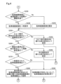
- FIG. 2 is a flowchart showing the procedure of the parking route setting process according to the present embodiment.
- FIG. 3 is a flowchart showing the procedure of the parking route setting process according to the present embodiment.
- FIG. 4 is a flowchart showing the procedure of the parking route setting process according to the present embodiment.
- FIG. 5 is a flowchart showing the procedure of the reference point selection process according to the present embodiment.
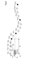
- FIG. 6 is an explanatory diagram showing an example of a reference path and a parking path.
- the vehicle condition detection unit 100 detects the vehicle condition of the vehicle M.
- the vehicle condition includes at least the position of the vehicle M and the steering angle at that position.
- the automatic parking system 10 of this embodiment is equipped with an image sensor 110 and a steering angle sensor 120 as the vehicle condition detection unit 100.
- the image sensor 110 is mounted on the vehicle M so as to capture images of the front, rear, left and right of the vehicle M, for example.
- the image sensor 110 captures images of objects and markers (hereinafter also referred to as "reference objects") present around the vehicle M, and acquires the captured images.
- the steering angle sensor 120 detects the steering angle of the steering wheels while the vehicle M is traveling.
- the automatic parking system 10 may also include, as the vehicle condition detection unit 100, various sensors such as millimeter wave radar, ultrasonic sensors, and LiDAR (Light Detection and Ranging) that detect targets around the vehicle M, a GNSS receiver that receives navigation signals from artificial satellites that make up the GNSS (Global Navigation Satellite System) to detect the current position (longitude and latitude) of the vehicle M, and a vehicle speed sensor that detects the speed of the vehicle M.
- various sensors such as millimeter wave radar, ultrasonic sensors, and LiDAR (Light Detection and Ranging) that detect targets around the vehicle M
- GNSS receiver that receives navigation signals from artificial satellites that make up the GNSS (Global Navigation Satellite System) to detect the current position (longitude and latitude) of the vehicle M
- GNSS Global Navigation Satellite System
- the reference route storage unit 200 of this embodiment is configured as an ECU including a CPU 210 and a memory 220.
- the reference route storage unit 200 stores a reference route.
- the "reference route” refers to the route traveled when the vehicle M travels a section from an arbitrary starting point to a target point (hereinafter also referred to as a "learning section") driven by the driver.
- the reference route is made up of a plurality of waypoints which are points indicating the above-mentioned vehicle state in the learning section.
- the starting point of the reference route is set to the position of the vehicle M at the time when the driver operates a button to instruct the start of a learning mode in which the reference route is stored.
- the target point is set to the position of the vehicle M at the time when the driver operates a button to instruct the end of the learning mode. If an upper limit route length that can be stored as a reference route is previously determined, the target point is set to the position of the vehicle M at the time when the route length from the starting point reaches the upper limit route length.
- the reference route storage unit 200 stores a plurality of waypoints indicating the vehicle state acquired by the vehicle state detection unit 100 as waypoint data Pw in the memory 220 each time a predetermined distance is traveled. More specifically, the reference route storage unit 200 calculates the position of the vehicle M based on the reference target by analyzing the captured image at each point acquired from the image sensor 110 each time a predetermined distance is traveled, and stores the calculated position of the vehicle M as waypoint data Pw in the memory 220. In addition, the reference route storage unit 200 acquires the steering angle at each point from the steering angle sensor 120 each time a predetermined distance is traveled, and stores the acquired steering angle in the memory 220 as waypoint data Pw.
- the data indicating the waypoint that is the start point of the learning section among the waypoint data Pw includes at least the position of the start point based on the reference target and the steering angle at the start point.
- data indicating other way points following the starting point includes at least the position of each way point relative to the starting point and the steering angle at each way point.
- the parking route setting unit 300 of this embodiment is configured as an ECU equipped with a CPU 310 and a memory 320.
- the parking route setting unit 300 sets a parking route from the automatic parking start point to the target point of the above-mentioned learning section.
- the automatic parking start point may be any point that does not coincide with the start point of the above-mentioned reference route.
- the parking route setting unit 300 also stores parking route candidates that are set as parking route candidates. In FIG. 1, four parking route candidates RT1 to RT4 are stored in the memory 320, but the number of parking route candidates stored in the memory 220 is not limited to four. The specific steps of the parking route setting method will be described later.
- the vehicle control unit 400 of this embodiment is configured as an ECU equipped with a CPU 410 and a memory 420.
- the vehicle control unit 400 controls the vehicle operation device 500 so that the vehicle M travels according to the operation of the accelerator pedal, brake pedal, or steering wheel by the driver, or according to a parking route set by the parking route setting unit 300.
- the vehicle operation device 500 includes a drive device 510, a brake device 520, and a steering device 530.
- the drive device 510 outputs a drive force for driving the vehicle M.
- the drive device 51 is, for example, an internal combustion engine, a motor, etc.
- the drive device 510 is electrically connected to the vehicle control unit 400, and the drive force is controlled by a control signal transmitted from the vehicle control unit 400.
- the brake device 520 outputs a braking force for braking the vehicle M.
- the brake device 520 is electrically connected to the vehicle control unit 400, and the braking force is controlled by a control signal transmitted from the vehicle control unit 400.
- the steering device 530 outputs a steering force for steering the vehicle M.
- the steering device 530 is, for example, a power steering device, etc.
- the steering device 530 is electrically connected to the vehicle control unit 400, and the steering force is controlled by a control signal transmitted from the vehicle control unit 400.
- A-2. Parking route setting process The automatic parking system 10 of this embodiment executes the parking route setting process shown in Figures 2 to 4 to set a parking route.
- the parking route is set to merge with the reference route from the current position of the vehicle M and reach the learned target point.
- the parking route setting process is started when the driver instructs the start of the parking route setting process by operating a button, for example.
- the automatic parking system 10 controls the vehicle operation device 500 to drive the vehicle M along the set parking route.
- step S110 shown in FIG. 2 the parking route setting unit 300 acquires the waypoint data Pw from the reference route memory unit 200.
- step S120 the parking route planning unit 300 acquires captured images of the surroundings of the vehicle M from the vehicle state detection unit 100.
- the parking route setting unit 300 uses the acquired way point data Pw and the captured image to identify the position of the start point of the reference route. More specifically, the parking route setting unit 300 identifies a reference target in the acquired captured image, and identifies the position of the start point by comparing it with the position of the start point indicated by the way point data Pw, which is based on the reference target. Note that the identification of the reference target in the captured image can be achieved by performing well-known image processing such as pattern matching.
- step S140 the parking route setting unit 300 executes a reference point selection process to select a reference point from the multiple via points indicated by the acquired via point data Pw.
- the "reference point” refers to a via point among the multiple via points that is to be preferentially used to attempt to merge from the current position to the reference route.
- FIG. 6 a reference route Wr consisting of via points Pw1 to Pw15 is shown.
- the via points Pw5 to Pw15 are shown by black circles, and the other via points are shown by white circles.
- the via point Pw3 shown with hatching will be described later.
- step S142 shown in FIG. 5 the parking path setting unit 300 selects a via point with a neutral steering angle (hereinafter also referred to as a "neutral point") from among the multiple via points as a reference point. Note that in the straight line portion of the reference path, the reference points are selected at predetermined intervals. In the example shown in FIG. 6, via points Pw7 and Pw11 are selected as reference points for neutral points.
- step S144 the parking path setting unit 300 determines whether the distance between the vehicle M and the reference path is equal to or greater than a predetermined threshold. As shown in FIG. 6, in this embodiment, the parking path setting unit 300 calculates, as the distance between the vehicle M and the reference path, the distance d1 along the rear wheel axis Ar from the vehicle reference point Cr, which is the intersection of the central axis Ac of the vehicle M in the width direction and the rear wheel axis Ar of the vehicle M, to the reference path.
- step S146 the parking route setting unit 300 selects a way point that is equal to or greater than a predetermined allowable distance from the vehicle M as a reference point.
- the "allowable distance” is a distance between the vehicle M and the way point that allows the vehicle M to merge with the reference route without abrupt steering, and is specified and set in advance by performing simulations or the like.
- FIG. 6 shows an example in which the distance d1 is determined to be equal to or greater than the threshold.
- the parking route setting unit 300 selects a way point that is equal to or greater than the allowable distance from the vehicle reference point Cr along the central axis Ac as a reference point.
- FIG. 6 shows an example in which via point Pw5 is selected as the reference point because the distance d2 along the central axis Ac from the vehicle reference point Cr is equal to or greater than the allowable distance.
- via point Pw3 which is located on a straight path and shown hatched, has a neutral steering angle, but is not selected as the reference point because the distance along the central axis Ac from the vehicle reference point Cr is less than the allowable distance.
- Via point Pw3 corresponds to the "nearest neutral point" in this disclosure.
- step S144 determines that the distance between the vehicle M and the reference route is less than the threshold (step S144: No). If it is determined that the distance between the vehicle M and the reference route is less than the threshold (step S144: No), the parking route setting unit 300 does not execute step S146 and proceeds to step S148.
- step S148 the parking route setting unit 300 selects, from among the multiple via points, the via point located at the end of the reference route as the reference point.
- via point Pw15 located at the end of the reference route Wr is selected as the reference point. This completes the reference point selection process.
- step S150 shown in FIG. 2 the parking route setting unit 300 sets the automatic parking start point of the vehicle M as the starting point and the first reference point as the tentative end point.
- the automatic parking start point Pst which is the vehicle reference point Cr at the start of the parking route generation process, is set as the starting point
- the intermediate point Pw5 is set as the tentative end point.
- step S160 the parking route setting unit 300 sets a one-circle route from the set start point to the tentative end point.
- a one-circle route means a route in which a start point and a tentative end point are connected by a single arc.
- the one-circle route is formed as an arc that is tangent to the reference route with the tentative end point as a tangent point.
- the end point of the set one-circle route does not necessarily have to coincide with the tentative end point, and the one-circle route may be a route up to the vicinity of the tentative end point. Since a one-circle route does not require a change in steering angle midway along the route, it is possible to prevent the running state of the vehicle M from becoming unstable, compared to a two-circle route described below.
- step S170 shown in FIG. 3 the parking path setting unit 300 determines whether the radius of curvature of the set one-circle path is less than a predetermined threshold value. If it is determined that the radius of curvature is less than the threshold value (step S170: Yes), in step S180, the parking path setting unit 300 sets a two-circle path from the set start point to the tentative end point.
- the two-circle path means a path in which the start point and the tentative end point are connected by two arcs.
- the arc that connects to the tentative end point is formed as an arc that is tangent to the reference path with the tentative end point as the tangent point.
- FIG. 6 shows a parking path Wp that is set as a two-circle path connecting the automatic parking start point Pst, which is the starting point, and the via point Pw5, which is the tentative end point.
- the parking path Wp is an S-shaped path formed by two mutually circumscribing circular arcs.
- step S190 shown in FIG. 3 the parking route setting unit 300 selects, as a parking route candidate, the route between the set one-circle route and the set two-circle route, whose end point is closer to the set tentative end point.
- step S192 the parking route setting unit 300 selects the circular route as a candidate parking route.
- step S200 the parking route setting unit 300 determines whether the distance between the tentative end point and the end point of the parking route candidate is less than a predetermined threshold. If it is determined that the distance between the tentative end point and the end point of the parking route candidate is less than the threshold (step S200: Yes), in step S210, the parking route setting unit 300 adopts the parking route candidate selected in the above-mentioned step S190 as the parking route.
- step S220 the parking route setting unit 300 determines whether route setting has been completed up to the last reference point on the adopted parking route.
- step S220 If it is determined that route setting has been completed up to the last reference point (step S220: Yes), the parking route setting unit 300 ends the parking route setting process.
- step S222 the parking route setting unit 300 sets the end point of the adopted parking route as the new start point and the next reference point as the new tentative end point.
- the next reference point is the waypoint Pw7.
- the parking route setting unit 300 then executes the above-mentioned step S160 again.
- step S230 shown in FIG. 4 the parking route setting unit 300 determines whether the difference between the parking route candidate and the reference route is less than the threshold.
- the reference route can be said to be a route that reflects the driver's intention for parking the vehicle M, such as avoiding obstacles such as flower beds. If automatic parking is performed by adopting a parking route that is significantly different from such a route, there is a risk of a problem such as contacting an obstacle contrary to the driver's intention. In order to avoid such a problem, the parking route setting unit 300 performs the determination in step S230.
- the parking route setting unit 300 calculates the distance between the reference route based on each point along a direction perpendicular to the parking route candidate at multiple points located at predetermined intervals on the parking route candidate, and determines the average value of such distances as the difference between the parking route candidate and the reference route.
- step S240 the parking route setting unit 300 temporarily stores the parking route candidate in the memory 320.
- step S242 the parking route setting unit 300 rejects the parking route candidate and does not temporarily store it in the memory 320.
- step S250 the parking route setting unit 300 determines whether the route has already been set as a temporary end point for the via point immediately preceding the via point that is set as the temporary end point.
- the "previous via point” refers to another via point adjacent to the via point that is set as the temporary end point and is located closer to the vehicle M.
- the via point Pw4 corresponds to the "previous via point" of the via point Pw5.
- step S252 the parking route setting unit 300 does not change the starting point and sets the previous via point as a new tentative end point.
- the parking route setting unit 300 then executes the above-mentioned step S160 again. In this way, even if the parking route setting unit 300 sets the reference point as the tentative end point and attempts to set a route, if the distance between the tentative end point and the end point of the parking route candidate is equal to or greater than the threshold value (step S200: No), the parking route setting unit 300 attempts to set a route by going back one via point at a time. In the example shown in FIG.
- the parking route setting unit 300 attempts to set a route using the via point Pw5, which is the reference point, as a tentative end point, and then attempts to set the via points Pw4, Pw3, Pw2, and Pw1 in that order as tentative end points until a parking route candidate is set in which the distance between the tentative end point and the end point of the parking route candidate is less than the threshold (step S200: Yes).
- step S200 Yes
- the parking route setting unit 300 attempts to set a route using the via point Pw5, which is the reference point, as a tentative end point, and then attempts to set the via points Pw4, Pw3, Pw2, and Pw1 in that order as tentative end points until a parking route candidate is set in which the distance between the tentative end point and the end point of the parking route candidate is less than the threshold.
- step S260 the parking route setting unit 300 determines whether the route has already been set with the last reference point as the tentative end point. In other words, in this step, the parking route setting unit 300 determines whether the route has already been set for all via points.
- step S262 the parking route setting unit 300 does not change the starting point and sets the next reference point as a new tentative end point. After that, the parking route setting unit 300 executes the above-mentioned step S160 again. In the example shown in FIG. 6, the parking route setting unit 300 attempts to set a route with via point Pw1 as the tentative end point, and then attempts to set a route with via point Pw7, which is the reference point next to via point Pw5, as the new tentative end point.
- the parking route setting unit 300 attempts to set the route by setting the intermediate points Pw6, Pw11, Pw10, Pw9, Pw8, Pw15, Pw14, Pw13, and Pw12 as the tentative end point in this order until a parking route candidate is set in which the distance between the tentative end point and the end point of the parking route candidate is less than the threshold (step S200: Yes).
- step S260 if it is determined that the route has already been set with the last reference point as the temporary end point (step S260: Yes), in other words, if it is determined that route setting has been attempted for all intermediate points, in step S270, the parking route setting unit 300 determines whether there are any parking route candidates temporarily stored in the memory 320.
- step S280 the parking route setting unit 300 adopts the parking route candidate with the shortest distance between the end point of the parking route candidate and the tentative end point as the parking route. After that, the parking route setting unit 300 executes the above-mentioned step S220 again.
- step S282 the parking route setting unit 300 determines that there are no available parking routes and ends the parking route setting process.
- the parking path setting unit 300 sets a parking path with the neutral point as a temporary end point, so that the vehicle can merge with the reference path with a neutral steering angle, and this can prevent the vehicle M's driving state from becoming unstable, compared to a configuration in which the merging point with the reference path is determined only by the travel angle of the vehicle M relative to the reference path. Also, compared to a configuration in which a parking path is set with a waypoint where the steering angle is inclined to either the left or right as a temporary end point, the vehicle can easily take a course to the left or right on the parking path after reaching the temporary end point. This can prevent the travel direction from being restricted on the parking path after reaching the temporary end point.
- the parking route is re-set with a second via point, which is a via point different from the first via point and is located closer to the vehicle M than the first via point, as the tentative end point. This makes it easier to set a parking route that merges more quickly from the automatic parking start point to the reference route and has a smaller difference from the reference route.
- the parking route is not set with the nearest neutral point as the tentative end point, but instead, a via point among multiple via points whose distance from vehicle M is equal to or greater than the allowable distance is set as the tentative end point, thereby preventing abrupt steering when joining the reference route from the automatic parking start point Pst.
- step S250 when the parking route setting unit 300 has not yet generated a route with the previous via point as a tentative end point in step S250 of the parking route setting process (step S250: No), the parking route setting unit 300 sets the previous via point as a new tentative end point (step S252), but the present disclosure is not limited thereto. In such a case, the parking route setting unit 300 may set a via point two or more before as a new tentative end point.
- the automatic parking system 10 of this form also achieves the same effect as the above embodiment.
- since a via point closer to the vehicle M than the previous via point is set as a tentative end point, it is easier to set a parking route that merges more quickly from the automatic parking start point to the reference route.
- step S250 if the parking route setting unit 300 has already generated a route with the previous via point as a tentative end point in step S250 of the parking route setting process (step S250: Yes), the parking route setting unit 300 does not attempt to generate a route by setting the previous via point as a new tentative end point, but the present disclosure is not limited to this. Even in such a case, the parking route setting unit 300 may attempt to generate a route by setting the previous via point as a new tentative end point.
- step S3 if the parking route setting unit 300 has not yet generated a route with the last reference point as the tentative end point in step S260 of the parking route setting process (step S260: No), the parking route setting unit 300 sets the next reference point as a new tentative end point (step S262), but the present disclosure is not limited to this. In such a case, the parking route setting unit 300 may set a waypoint that is not a reference point as the tentative end point.
- the parking path setting unit 300 selects the neutral point as the reference point in step S142 of the reference point selection process, but the present disclosure is not limited to this.
- the parking path setting unit 300 does not have to select the neutral point as the reference point.
- a second via point which is a via point different from the first via point and is located closer to the vehicle M than the first via point, as a temporary end point, it is possible to easily set a parking path that merges more quickly from the automatic parking start point to the reference path and has a small difference from the reference path.
- step S144: No when the distance between vehicle M and the reference route is less than the threshold value in step S144 of the reference point selection process (step S144: No), the parking route setting unit 300 does not select a way point that is more than the allowable distance away from vehicle M as a reference point, but the present disclosure is not limited to this. Even when the distance between vehicle M and the reference route is more than the threshold value (step S144: No), the parking route setting unit 300 may select a way point that is more than the allowable distance away from vehicle M as a reference point. This type of automatic parking system 10 can also suppress abrupt steering when joining the reference route from the automatic parking start point Pst.
- step S200 when the distance between the tentative end point and the parking route candidate is equal to or greater than the threshold value in step S200 of the parking route setting process (step S200: No), the parking route setting unit 300 executes the processes from step S230 to step S282, but the present disclosure is not limited thereto. In such a case, the parking route setting unit 300 does not need to execute the processes from step S230 to step S282.
- the parking route is set with the neutral point as the tentative end point, so that the vehicle M can merge with the reference route with the steering angle neutral, and the vehicle M's running state can be prevented from becoming unstable.
- the vehicle M can be prevented from being restricted in the traveling direction in the parking route after reaching the tentative end point.
- the automated parking system 10 and the method described herein may be realized by a dedicated computer provided by configuring a processor and a memory programmed to execute one or more functions embodied in a computer program.
- the automated parking system 10 and the method described herein may be realized by a dedicated computer provided by configuring a processor with one or more dedicated hardware logic circuits.
- the automated parking system 10 and the method described herein may be realized by one or more dedicated computers configured by a combination of a processor and a memory programmed to execute one or more functions and a processor configured with one or more hardware logic circuits.
- the computer program may also be stored in a computer-readable non-transient tangible recording medium as instructions executed by the computer.
- the present disclosure is not limited to the above-mentioned embodiment, and can be realized in various configurations without departing from the spirit of the present disclosure.
- the technical features in each embodiment corresponding to the technical features in the form described in the Summary of the Invention column can be appropriately replaced or combined in order to solve some or all of the above-mentioned problems or to achieve some or all of the above-mentioned effects.
- the technical feature is not described as essential in this specification, it can be appropriately deleted.
- An automatic parking system (10) for automatically driving a vehicle (M) and parking the vehicle A vehicle state detection unit (100) that detects a vehicle state including at least a position and a steering angle of the vehicle;
- a reference route storage unit (200) that stores a reference route (Wr) consisting of a plurality of waypoints (Pw1 to Pw15) that are points that indicate the vehicle state when the vehicle travels to a target point by being driven by a driver;
- a vehicle control unit (400) that controls the vehicle to travel along the parking path; Equipped with The parking path setting unit sets the parking path by setting a neutral point, which is a point where the steering angle is neutral, among the plurality of via points as a temporary end point.
- An automatic parking system that automatically drives a vehicle and parks the vehicle, a vehicle state detection unit that detects a vehicle state including at least a position and a steering angle of the vehicle; a reference route storage unit that stores a reference route including a plurality of waypoints that indicate a vehicle state when the vehicle is driven by a driver to a target point; A parking route setting unit that sets a parking route from an automatic parking start point to the target point; A vehicle control unit that controls the vehicle to travel along the parking path; Equipped with When a difference between the parking route, which is set with a first via point that is one of the plurality of via points as a tentative end point, and the reference route is equal to or greater than a predetermined threshold distance, the parking route setting unit sets the parking route again with a second via point that is a via point different from the first via point and located closer to the vehicle than the first via point as a tentative end point.
- Automatic parking system (Form 3) The automatic parking system according to aspect 2, The parking path setting unit sets the parking path so that the reference path and the parking path merge at a neutral point, which is a point where the steering angle is neutral among the plurality of via points, as a temporary end point, as the first via point.
- Automatic parking system (Form 4) The automatic parking system according to claim 2 or 3, When the parking route setting unit has already attempted to set the parking route with the second via point as a tentative end point, the parking route setting unit does not set the parking route with the second via point as a target, and sets the parking route again with another via point for which the setting of the parking route has not yet been attempted as a tentative end point. Automatic parking system.
Landscapes
- Engineering & Computer Science (AREA)
- Automation & Control Theory (AREA)
- Transportation (AREA)
- Mechanical Engineering (AREA)
- Human Computer Interaction (AREA)
- Steering Control In Accordance With Driving Conditions (AREA)
- Navigation (AREA)
Abstract
Description
A-1.システム構成:
本実施形態の自動駐車システム10は、車両Mに搭載され、車両Mの走行状態や車両Mの周囲の環境に応じて車両Mを自動走行させ、車両Mの駐車を支援する。図1に示すように、自動駐車システム10は、車両状態検出部100と、基準経路記憶部200と、駐車経路設定部300と、車両制御部400とを備える。
本実施形態の自動駐車システム10は、図2~図4に示す駐車経路設定処理を実行し駐車経路を設定する。駐車経路は、車両Mの現在位置から基準経路に合流し、学習済みの目標地点に至るように設定される。駐車経路設定処理は、例えば運転者によるボタン操作により、駐車経路設定処理の開始が指示されることにより開始される。自動駐車システム10は、駐車経路設定処理により車両Mの現在位置から学習済みの目標地点までの駐車経路が設定されると、設定された駐車経路に沿って車両Mを走行させるように車両動作装置500を制御する。
(B1)上記実施形態において、駐車経路設定部300は、駐車経路設定処理のステップS250においてひとつ前の経由点を仮の終点として経路生成済みでない場合(ステップS250:No)、ひとつ前の経由点を新たな仮の終点として設定するが(ステップS252)、本開示はこれに限定されない。駐車経路設定部300は、かかる場合に、2つ以上前の経由点を新たな仮の終点として設定してもよい。かかる形態の自動駐車システム10によっても、上記実施形態と同様の効果を奏する。加えて、ひとつ前の経由点よりも車両Mに近い経由点を仮の終点に設定するので、自動駐車開始地点から基準経路へより早く合流する駐車経路をより設定しやすくできる。
(形態1)
車両(M)を自動走行させて前記車両を駐車させる自動駐車システム(10)であって、
前記車両の位置および操舵角度を少なくとも含む車両状態を検出する車両状態検出部(100)と、
運転者の運転により前記車両が目標地点まで走行した際の前記車両状態を示す点である複数の経由点(Pw1~Pw15)からなる基準経路(Wr)を記憶する基準経路記憶部(200)と、
自動駐車開始地点(Pst)から前記目標地点までの駐車経路(Wp)を設定する駐車経路設定部(300)と、
前記駐車経路に沿って走行するように前記車両を制御する車両制御部(400)と、
を備え、
前記駐車経路設定部は、前記複数の経由点のうち、前記操舵角度が中立である地点である中立地点を仮の終点として前記駐車経路を設定する、
自動駐車システム。
(形態2)
車両を自動走行させて前記車両を駐車させる自動駐車システムであって、
前記車両の位置および操舵角度を少なくとも含む車両状態を検出する車両状態検出部と、
運転者の運転により前記車両が目標地点まで走行した際の前記車両状態を示す点である複数の経由点からなる基準経路を記憶する基準経路記憶部と、
自動駐車開始地点から前記目標地点までの駐車経路を設定する駐車経路設定部と、
前記駐車経路に沿って走行するように前記車両を制御する車両制御部と、
を備え、
前記駐車経路設定部は、前記複数の経由点のうちの1つである第1の経由点を仮の終点として設定された前記駐車経路と、前記基準経路と、の差異が予め定められた閾値距離以上である場合に、前記複数の経由点のうち、前記第1の経由点とは異なる経由点であって、前記第1の経由点よりも前記車両に近い位置に位置する経由点である第2の経由点を仮の終点として、前記駐車経路を再度設定する、
自動駐車システム。
(形態3)
形態2に記載の自動駐車システムであって、
前記駐車経路設定部は、前記第1の経由点として、前記複数の経由点のうち、前記操舵角度が中立である地点である中立地点を仮の終点として、該中立地点において前記基準経路と前記駐車経路とが合流するように前記駐車経路を設定する、
自動駐車システム。
(形態4)
形態2または形態3に記載の自動駐車システムであって、
前記駐車経路設定部は、前記第2の経由点を仮の終点として前記駐車経路の設定を既に試みたことがある場合、前記第2の経由点を対象とする前記駐車経路の設定を行わず、前記駐車経路の設定を未だ試みていない他の経由点を仮の終点として前記駐車経路を再度設定する、
自動駐車システム。
(形態5)
形態1または形態3に記載の自動駐車システムであって、
前記駐車経路設定部は、前記車両に最も近い前記中立地点である最近傍中立地点と、前記車両と、の距離が、予め定められた許容距離未満である場合、前記最近傍中立地点を仮の終点とする前記駐車経路の設定を行わず、前記複数の経由点のうち、前記車両との距離が前記許容距離以上である経由点を仮の終点として前記駐車経路を設定する、
自動駐車システム。
Claims (5)
- 車両(M)を自動走行させて前記車両を駐車させる自動駐車システム(10)であって、
前記車両の位置および操舵角度を少なくとも含む車両状態を検出する車両状態検出部(100)と、
運転者の運転により前記車両が目標地点まで走行した際の前記車両状態を示す点である複数の経由点(Pw1~Pw15)からなる基準経路(Wr)を記憶する基準経路記憶部(200)と、
自動駐車開始地点(Pst)から前記目標地点までの駐車経路(Wp)を設定する駐車経路設定部(300)と、
前記駐車経路に沿って走行するように前記車両を制御する車両制御部(400)と、
を備え、
前記駐車経路設定部は、前記複数の経由点のうち、前記操舵角度が中立である地点である中立地点を仮の終点として前記駐車経路を設定する、
自動駐車システム。 - 車両を自動走行させて前記車両を駐車させる自動駐車システムであって、
前記車両の位置および操舵角度を少なくとも含む車両状態を検出する車両状態検出部と、
運転者の運転により前記車両が目標地点まで走行した際の前記車両状態を示す点である複数の経由点からなる基準経路を記憶する基準経路記憶部と、
自動駐車開始地点から前記目標地点までの駐車経路を設定する駐車経路設定部と、
前記駐車経路に沿って走行するように前記車両を制御する車両制御部と、
を備え、
前記駐車経路設定部は、前記複数の経由点のうちの1つである第1の経由点を仮の終点として設定された前記駐車経路と、前記基準経路と、の差異が予め定められた閾値距離以上である場合に、前記複数の経由点のうち、前記第1の経由点とは異なる経由点であって、前記第1の経由点よりも前記車両に近い位置に位置する経由点である第2の経由点を仮の終点として、前記駐車経路を再度設定する、
自動駐車システム。 - 請求項2に記載の自動駐車システムであって、
前記駐車経路設定部は、前記第1の経由点として、前記複数の経由点のうち、前記操舵角度が中立である地点である中立地点を仮の終点として、該中立地点において前記基準経路と前記駐車経路とが合流するように前記駐車経路を設定する、
自動駐車システム。 - 請求項2または請求項3に記載の自動駐車システムであって、
前記駐車経路設定部は、前記第2の経由点を仮の終点として前記駐車経路の設定を既に試みたことがある場合、前記第2の経由点を対象とする前記駐車経路の設定を行わず、前記駐車経路の設定を未だ試みていない他の経由点を仮の終点として前記駐車経路を再度設定する、
自動駐車システム。 - 請求項1または請求項3に記載の自動駐車システムであって、
前記駐車経路設定部は、前記車両に最も近い前記中立地点である最近傍中立地点と、前記車両と、の距離が、予め定められた許容距離未満である場合、前記最近傍中立地点を仮の終点とする前記駐車経路の設定を行わず、前記複数の経由点のうち、前記車両との距離が前記許容距離以上である経由点を仮の終点として前記駐車経路を設定する、
自動駐車システム。
Priority Applications (3)
| Application Number | Priority Date | Filing Date | Title |
|---|---|---|---|
| JP2025526071A JPWO2024253002A1 (ja) | 2023-06-06 | 2024-05-29 | |
| CN202480037852.XA CN121285492A (zh) | 2023-06-06 | 2024-05-29 | 自动停车系统 |
| US19/409,330 US20260116378A1 (en) | 2023-06-06 | 2025-12-04 | Automatic parking system |
Applications Claiming Priority (2)
| Application Number | Priority Date | Filing Date | Title |
|---|---|---|---|
| JP2023092858 | 2023-06-06 | ||
| JP2023-092858 | 2023-06-06 |
Related Child Applications (1)
| Application Number | Title | Priority Date | Filing Date |
|---|---|---|---|
| US19/409,330 Continuation US20260116378A1 (en) | 2023-06-06 | 2025-12-04 | Automatic parking system |
Publications (1)
| Publication Number | Publication Date |
|---|---|
| WO2024253002A1 true WO2024253002A1 (ja) | 2024-12-12 |
Family
ID=93795955
Family Applications (1)
| Application Number | Title | Priority Date | Filing Date |
|---|---|---|---|
| PCT/JP2024/019716 Ceased WO2024253002A1 (ja) | 2023-06-06 | 2024-05-29 | 自動駐車システム |
Country Status (4)
| Country | Link |
|---|---|
| US (1) | US20260116378A1 (ja) |
| JP (1) | JPWO2024253002A1 (ja) |
| CN (1) | CN121285492A (ja) |
| WO (1) | WO2024253002A1 (ja) |
Citations (4)
| Publication number | Priority date | Publication date | Assignee | Title |
|---|---|---|---|---|
| JP2013530867A (ja) * | 2010-06-09 | 2013-08-01 | ヴァレオ・シャルター・ウント・ゼンゾーレン・ゲーエムベーハー | 駐車スペースへの駐車時における自動車運転者支援方法、運転者支援装置、および自動車 |
| JP2016060232A (ja) * | 2014-09-12 | 2016-04-25 | アイシン精機株式会社 | 出庫支援装置 |
| JP2017206181A (ja) * | 2016-05-20 | 2017-11-24 | アイシン・エィ・ダブリュ株式会社 | 自動運転支援装置及びコンピュータプログラム |
| JP2021126925A (ja) * | 2020-02-12 | 2021-09-02 | 株式会社Subaru | 制御装置、制御方法およびプログラム |
-
2024
- 2024-05-29 CN CN202480037852.XA patent/CN121285492A/zh active Pending
- 2024-05-29 JP JP2025526071A patent/JPWO2024253002A1/ja active Pending
- 2024-05-29 WO PCT/JP2024/019716 patent/WO2024253002A1/ja not_active Ceased
-
2025
- 2025-12-04 US US19/409,330 patent/US20260116378A1/en active Pending
Patent Citations (4)
| Publication number | Priority date | Publication date | Assignee | Title |
|---|---|---|---|---|
| JP2013530867A (ja) * | 2010-06-09 | 2013-08-01 | ヴァレオ・シャルター・ウント・ゼンゾーレン・ゲーエムベーハー | 駐車スペースへの駐車時における自動車運転者支援方法、運転者支援装置、および自動車 |
| JP2016060232A (ja) * | 2014-09-12 | 2016-04-25 | アイシン精機株式会社 | 出庫支援装置 |
| JP2017206181A (ja) * | 2016-05-20 | 2017-11-24 | アイシン・エィ・ダブリュ株式会社 | 自動運転支援装置及びコンピュータプログラム |
| JP2021126925A (ja) * | 2020-02-12 | 2021-09-02 | 株式会社Subaru | 制御装置、制御方法およびプログラム |
Also Published As
| Publication number | Publication date |
|---|---|
| JPWO2024253002A1 (ja) | 2024-12-12 |
| US20260116378A1 (en) | 2026-04-30 |
| CN121285492A (zh) | 2026-01-06 |
Similar Documents
| Publication | Publication Date | Title |
|---|---|---|
| JP6947849B2 (ja) | 車両制御装置 | |
| JP2018077565A (ja) | 車両制御装置 | |
| JP6650904B2 (ja) | 車両制御装置 | |
| JP6507862B2 (ja) | 周辺監視装置及び運転支援装置 | |
| JP6176264B2 (ja) | 自動運転車両システム | |
| CN112236344B (zh) | 车辆的驾驶辅助控制装置、驾驶辅助系统以及驾驶辅助控制方法 | |
| US11285954B2 (en) | Vehicle, and control apparatus and control method thereof | |
| JP6825081B2 (ja) | 車両制御装置及び車両制御方法 | |
| CN110155040A (zh) | 停车辅助装置 | |
| US12384413B2 (en) | Vehicle determining a driving route based on pass priority and a method for operating the vehicle | |
| US11780474B2 (en) | Vehicle travel control method and vehicle travel control device | |
| JP7052745B2 (ja) | 車両制御システム | |
| CN113753028A (zh) | 驾驶辅助装置、驾驶辅助方法及电脑可读取记录介质 | |
| US11884276B2 (en) | Travel assistance method and travel assistance device | |
| JP2019014381A (ja) | 駐車支援方法及び駐車制御装置 | |
| JP6901043B2 (ja) | 車両制御方法及び車両制御装置 | |
| JP2023091170A (ja) | 運転状態判断方法、自動運転システム | |
| JP2010132029A (ja) | 駐車支援装置 | |
| RU2735752C1 (ru) | Способ определения поворота направо/налево и устройство определения поворота направо/налево для транспортного средства с содействием вождению | |
| US11875542B2 (en) | Parking assist system | |
| JP2004219316A (ja) | 車両進行路推定装置 | |
| JP2020015345A (ja) | 車両制御装置 | |
| US20230303162A1 (en) | Vehicle control device | |
| JP7677051B2 (ja) | 車両用制御装置及び車両用制御方法 | |
| US20260116378A1 (en) | Automatic parking system |
Legal Events
| Date | Code | Title | Description |
|---|---|---|---|
| 121 | Ep: the epo has been informed by wipo that ep was designated in this application |
Ref document number: 24819233 Country of ref document: EP Kind code of ref document: A1 |
|
| ENP | Entry into the national phase |
Ref document number: 2025526071 Country of ref document: JP Kind code of ref document: A |
|
| WWE | Wipo information: entry into national phase |
Ref document number: 2025526071 Country of ref document: JP |
|
| NENP | Non-entry into the national phase |
Ref country code: DE |
|
| 122 | Ep: pct application non-entry in european phase |
Ref document number: 24819233 Country of ref document: EP Kind code of ref document: A1 |