WO2024253014A1 - Battery module - Google Patents
Battery module Download PDFInfo
- Publication number
- WO2024253014A1 WO2024253014A1 PCT/JP2024/019842 JP2024019842W WO2024253014A1 WO 2024253014 A1 WO2024253014 A1 WO 2024253014A1 JP 2024019842 W JP2024019842 W JP 2024019842W WO 2024253014 A1 WO2024253014 A1 WO 2024253014A1
- Authority
- WO
- WIPO (PCT)
- Prior art keywords
- holes
- battery
- battery cells
- battery cell
- upper plate
- Prior art date
- Legal status (The legal status is an assumption and is not a legal conclusion. Google has not performed a legal analysis and makes no representation as to the accuracy of the status listed.)
- Ceased
Links
Images
Classifications
-
- Y—GENERAL TAGGING OF NEW TECHNOLOGICAL DEVELOPMENTS; GENERAL TAGGING OF CROSS-SECTIONAL TECHNOLOGIES SPANNING OVER SEVERAL SECTIONS OF THE IPC; TECHNICAL SUBJECTS COVERED BY FORMER USPC CROSS-REFERENCE ART COLLECTIONS [XRACs] AND DIGESTS
- Y02—TECHNOLOGIES OR APPLICATIONS FOR MITIGATION OR ADAPTATION AGAINST CLIMATE CHANGE
- Y02E—REDUCTION OF GREENHOUSE GAS [GHG] EMISSIONS, RELATED TO ENERGY GENERATION, TRANSMISSION OR DISTRIBUTION
- Y02E60/00—Enabling technologies; Technologies with a potential or indirect contribution to GHG emissions mitigation
- Y02E60/10—Energy storage using batteries
Definitions
- the present invention relates to a battery module.
- a battery module comprises multiple battery cells stacked in a specific direction and a housing that houses the multiple battery cells.
- Patent Document 1 describes a battery module.
- the battery module includes a plurality of battery cells stacked in a specific direction, a pair of pressure plates, and a pair of side wall plates.
- the pair of pressure plates are arranged on both sides of the plurality of battery cells in the specific direction.
- the pair of side wall plates are arranged on both sides of the plurality of battery cells in a direction perpendicular to the specific direction.
- Patent Document 2 describes a battery module.
- the battery module includes a plurality of battery cells, a module upper plate, and a module lower plate.
- the module upper plate and the module lower plate are provided with a plurality of holes.
- Patent Document 3 describes a battery module.
- the battery module includes a battery pack and a battery pack case.
- a through hole is provided in the upper plate of the battery pack case.
- One example of the objective of aspect 1 of the present invention is to suppress the effect of gas discharged from the housing on the tabs of the battery cells.
- Other objectives of aspect 1 of the present invention will become apparent from the description of this specification.
- Gas may be generated from the battery cell when abnormal heat generation occurs in the battery cell.
- the gas generated from the battery cell may be discharged from the housing through a hole provided in the housing.
- the housing has a hole, it becomes difficult to improve the airtightness of the housing when the battery cell is operating normally.
- the housing does not have a hole, it may become difficult to discharge the gas from the housing when abnormal heat generation occurs in the battery cell.
- One example of the objective of aspect 2 of the present invention is to simultaneously improve the airtightness of the housing when the battery cell is operating normally and to allow gas to escape from the housing when abnormal heat generation occurs in the battery cell.
- Other objectives of aspect 2 of the present invention will become apparent from the description in this specification.
- Aspect 1 of the present invention is as follows:
- the "first direction”, “second direction” and “third direction” in the following aspect 1 correspond to the Y direction, the X direction and the Z direction, respectively, in the following embodiments.
- 1.1 A plurality of battery cells stacked in a predetermined first direction, each having a tab located on a side in a second direction perpendicular to the first direction; a housing for housing the plurality of battery cells, the housing having a plate covering a side portion of the plurality of battery cells in a third direction perpendicular to both the first direction and the second direction; Equipped with the plate defines a plurality of holes for venting gases exhausted from the battery cells;
- a battery module wherein a ratio of the holes in a central portion of the plate in the second direction to a portion overlapping the tab in the third direction is greater than a ratio of the holes in the portion of the plate overlapping the tab in the third direction.
- a battery module as described in 1.1 wherein a ratio of the holes in a central portion of the plate in the first direction to a portion overlapping in the third direction with at least one battery cell on one end side of the plate in the first direction is greater than a ratio of the holes in the portion overlapping in the third direction with the at least one battery cell on one end side of the plate in the first direction.
- 1.3 further comprising a covering member at least a portion of which covers at least one of the plurality of holes; The battery module according to 1.1 or 1.2, wherein the covering member opens the at least one of the plurality of holes when abnormal heat generation occurs in the battery cell.
- At least some of the holes are arranged at a predetermined pitch in the first direction,
- 1.5 The battery module described in any one of 1.1 to 1.4, wherein the dimension of the hole in the first direction is equal to or smaller than the dimension of the battery cell in the first direction.
- Aspect 2 of the present invention is as follows.
- 2.1 A plurality of battery cells; a housing that defines a hole for discharging gas discharged from the battery cells and that houses the plurality of battery cells; a covering member at least partially covering the hole; Equipped with The covering member opens the hole when abnormal heat generation occurs in the battery cell.
- 2.2 The battery module according to 2.1, wherein the melting point of the covering member is equal to or lower than the temperature around the covering member when the abnormal heat generation occurs.
- the covering member has electrical insulation properties.
- the impact of gas discharged from the housing on the battery cell tabs can be suppressed.
- aspect 2 of the present invention it is possible to improve the airtightness of the housing when the battery cell is operating normally, while also allowing gas to escape from the housing when the battery cell generates abnormal heat.
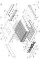
- FIG. 2 is an exploded top perspective view of the battery module according to the embodiment.
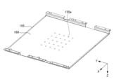
- FIG. 4 is a bottom perspective view of an upper plate according to the embodiment.
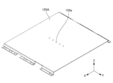
- FIG. 11 is a top perspective view of an upper plate according to a modified example.
- FIG. 1 is an exploded perspective view of the upper part of a battery module 100 according to an embodiment.
- FIG. 2 is a perspective view of the lower part of an upper plate 155 according to an embodiment.
- the X direction indicates the front-rear direction of the battery module 100.
- the Y direction is perpendicular to the X direction.
- the Y direction indicates the left-right direction of the battery module 100.
- the Z direction is perpendicular to both the X and Y directions.
- the Z direction indicates the up-down direction of the battery module 100.
- the arrows pointing to the X direction, the Y direction and the Z direction indicate the front, left and up directions of the battery module 100, respectively.
- the tip side of the arrow indicating the X direction will be referred to as the +X side
- the opposite side of the tip of the arrow indicating the X direction will be referred to as the -X side
- the tip side of the arrow indicating the Y direction will be referred to as the +Y side
- the opposite side of the tip of the arrow indicating the Y direction will be referred to as the -Y side
- the tip side of the arrow indicating the Z direction will be referred to as the +Z side
- the opposite side of the tip of the arrow indicating the Z direction will be referred to as the -Z side.
- the relationship between the X, Y, and Z directions and the front-rear, left-right, and up-down directions of the battery module 100 is not limited to the above example.
- the battery module 100 will be described with reference to Figure 1.
- the battery module 100 has a plurality of battery cells 110, a plurality of compression pads 120, a front voltage detection device 130, a rear voltage detection device 140, and a housing 150.
- the battery cells 110 are stacked in the Y direction.
- the compression pads 120 and the battery cells 110 are stacked alternately in the Y direction.
- Each compression pad 120 is disposed between adjacent battery cells 110 in the Y direction and on both sides of the battery cells 110 in the Y direction.
- the battery cells 110 and the compression pads 120 stacked alternately in the Y direction are referred to as a stack of battery cells 110.
- the dimension of each battery cell 110 in the X direction is the dimension in the longitudinal direction of each battery cell 110.
- the dimension of each battery cell 110 in the Z direction is the dimension in the lateral direction of each battery cell 110.
- the dimension of each battery cell 110 in the Y direction is the dimension in the thickness direction of each battery cell 110.
- the shape of each battery cell 110 is not limited to this example.
- Each battery cell 110 includes a battery element (not shown), an exterior material 112, a positive electrode tab 114, and a negative electrode tab 116.
- the battery element includes a plurality of positive electrodes and a plurality of negative electrodes (not shown) stacked alternately in the Y direction, and a separator (not shown) located between adjacent positive electrodes and negative electrodes in the Y direction.
- the exterior material 112 seals the battery element and an electrolyte (not shown).
- the positive electrode tab 114 is electrically connected to the positive electrode of the battery element.
- the positive electrode tab 114 is pulled out from one of both sides of the exterior material 112 in the X direction.
- the negative electrode tab 116 is electrically connected to the negative electrode of the battery element.
- the negative electrode tab 116 is pulled out from the other side of both sides of the exterior material 112 in the X direction.
- the structure of each battery cell 110 is not limited to this example.
- Each battery cell 110 may be an all-solid-state battery.
- an all-solid-state battery a solid electrolyte layer is provided in the portion corresponding to the separator.
- An all-solid-state battery does not contain an electrolyte.
- each battery cell 110 will be described as a battery cell containing an electrolyte.
- the battery cells 110 are electrically connected in a combination of series and parallel. Specifically, a cell group including at least two battery cells 110 adjacent to each other in the Y direction and connected in parallel is stacked in the Y direction and connected in series. At the front side of the stack of battery cells 110, a tab group 118 including the positive electrode tab 114 drawn from the battery cells 110 of one cell group connected in parallel and the negative electrode tab 116 drawn from the battery cells 110 of the other cell group connected in parallel are electrically connected to each other.
- the positive electrode tab 114 and the negative electrode tab 116 in the tab group 118 are joined to each other by, for example, laser welding.
- the tab group 118 is also located in the rear of the stack of battery cells 110.
- a plurality of cell groups are connected in series from the cell group located at one end side of the stack of battery cells 110 in the Y direction to the cell group located at the other end side of the stack of battery cells 110 in the Y direction.
- the tab group 118 located on the front side of the stack of battery cells 110 will be referred to as the front tab group 118
- the tab group 118 located on the rear side of the stack of battery cells 110 will be referred to as the rear tab group 118.
- the electrical connection of the multiple battery cells 110 is not limited to the above example.
- a stack of battery cells 110 may be formed by connecting single battery cells 110 in series.
- the front voltage detection device 130 detects the voltages of the multiple front tab groups 118.
- the front voltage detection device 130 includes a front protector 131, multiple front voltage detection terminals 132, multiple front voltage detection lines 133, a front connector 134, and a front bus bar 135.
- the front protector 131 covers the front of the stack of battery cells 110.
- the front protector 131 is, for example, an insulator such as resin.
- the front protector 131 defines a plurality of front openings 131a. Each of the plurality of front tab groups 118 is exposed forward through each of the plurality of front openings 131a.
- Each of the multiple front voltage detection terminals 132 is located in front of each of the multiple front tab groups 118.
- Each front voltage detection terminal 132 is, for example, a conductor such as metal.
- the rear surface of each front voltage detection terminal 132 and the front surface of each front tab group 118 are joined to each other by a joining method such as laser welding. Therefore, each front voltage detection terminal 132 and each front tab group 118 are electrically connected to each other. Therefore, the front voltage detection device 130 can detect the voltage of each front tab group 118 by each front voltage detection terminal 132.
- the multiple front voltage detection terminals 132 are held together by the front protector 131. Therefore, by placing the front protector 131 at an appropriate position relative to the stack of battery cells 110, each of the multiple front voltage detection terminals 132 can be placed at an appropriate position relative to each of the multiple front tab groups 118.
- each front voltage detection line 133 and each front voltage detection terminal 132 are electrically connected to each other.
- the other end of each front voltage detection line 133 and the front connector 134 are electrically connected to each other.
- the front voltage detection terminals 132 and the front connector 134 are electrically connected to each other via the front voltage detection lines 133.
- Each front voltage detection line 133 is routed between one end of each front voltage detection line 133 and the other end of each front voltage detection line 133 via the front protector 131.
- the front bus bar 135 is disposed at the right end of the front protector 131.
- the front bus bar 135 is electrically connected to the positive electrode tab 114 pulled forward from the battery cell 110 of the cell group located at the right end of the stack of battery cells 110.
- the front bus bar 135 functions as an external terminal for electrically connecting the battery module 100 to an external device such as another battery module.
- the rear voltage detection device 140 detects the voltages of the multiple rear tab groups 118.
- the rear voltage detection device 140 includes a rear protector 141, multiple rear voltage detection terminals 142, multiple rear voltage detection lines 143, a rear connector 144, and a rear bus bar 145.
- the rear protector 141 covers the rear of the stack of battery cells 110.
- the rear protector 141 is, for example, an insulator such as resin.
- the rear protector 141 defines a plurality of rear openings 141a. Each of the multiple rear tab groups 118 is exposed rearward through each of the multiple rear openings 141a.
- Each of the rear voltage detection terminals 142 is located behind each of the rear tab groups 118.
- Each rear voltage detection terminal 142 is, for example, a conductor such as metal.
- the front surface of each rear voltage detection terminal 142 and the rear surface of each rear tab group 118 are joined to each other by a joining method such as laser welding. Therefore, each rear voltage detection terminal 142 and each rear tab group 118 are electrically connected to each other. Therefore, the rear voltage detection device 140 can detect the voltage of each rear tab group 118 by each rear voltage detection terminal 142.
- the rear voltage detection terminals 142 are held together by the rear protector 141. Therefore, by placing the rear protector 141 at an appropriate position relative to the stack of battery cells 110, each of the rear voltage detection terminals 142 can be positioned at an appropriate position relative to each of the rear tab groups 118.
- each rear voltage detection line 143 and each rear voltage detection terminal 142 are electrically connected to each other.
- the other end of each rear voltage detection line 143 and the rear connector 144 are electrically connected to each other.
- the multiple rear voltage detection terminals 142 and the rear connector 144 are electrically connected to each other via the multiple rear voltage detection lines 143.
- Each rear voltage detection line 143 is routed between one end of each rear voltage detection line 143 and the other end of each rear voltage detection line 143 via the rear protector 141.
- the rear bus bar 145 is disposed at the left end of the rear protector 141.
- the rear bus bar 145 is electrically connected to the negative electrode tab 116 pulled out rearward from the battery cell 110 of the cell group located at the left end of the stack of battery cells 110.
- the rear bus bar 145 functions as an external terminal for electrically connecting the battery module 100 to an external device such as another battery module.
- the positive electrode tab 114 at the end of the multiple cell groups connected in series is pulled forward from the battery cell 110 of the cell group located at the right end side of the stack of battery cells 110
- the negative electrode tab 116 at the end of the multiple cell groups connected in series is pulled backward from the battery cell 110 of the cell group located at the left end side of the stack of battery cells 110.
- the front bus bar 135 is disposed on the right front side of the stack of battery cells 110
- the rear bus bar 145 is disposed on the left rear side of the stack of battery cells 110.
- the arrangement of the positive electrode tab 114 and the negative electrode tab 116 at the end of the multiple cell groups connected in series may differ depending on the number of battery cells 110 included in the stack of battery cells 110.
- the positive electrode tab 114 at the end of a group of cells connected in series may be pulled forward from the battery cell 110 of the cell group located at the right end of the stack of battery cells 110
- the negative electrode tab 116 at the end of a group of cells connected in series may be pulled forward from the battery cell 110 of the cell group located at the left end of the stack of battery cells 110.
- the bus bar electrically connected to the positive electrode tab 114 at the end of the group of cells connected in series is disposed on the right front side of the stack of battery cells 110
- the bus bar electrically connected to the negative electrode tab 116 at the end of the group of cells connected in series is disposed on the left front side of the stack of battery cells 110.
- the housing 150 houses a stack of battery cells 110.
- the housing 150 includes a front plate 151, a rear plate 152, a left plate 153, a right plate 154, an upper plate 155, and a lower plate 156.
- Each plate is, for example, a metal plate such as an aluminum plate.
- the front plate 151 covers the +X side of the stack of battery cells 110 and the +X side of the front voltage detection device 130.
- the rear plate 152 covers the -X side of the stack of battery cells 110 and the -X side of the rear voltage detection device 140.
- the left plate 153 covers the +Y side of the stack of battery cells 110.
- the right plate 154 covers the -Y side of the stack of battery cells 110.
- the upper plate 155 covers the +Z side of the stack of battery cells 110.
- the lower plate 156 covers the -Z side of the stack of battery cells 110.
- a thermally conductive adhesive 170 is disposed between the upper surface of the lower plate 156 and the lower surface of the stack of battery cells 110. Therefore, heat generated from the stack of battery cells 110 can be released toward the bottom of the battery module 100 through the thermally conductive adhesive 170.
- Abnormal heat generation in the battery cell 110 occurs, for example, when the electrodes of the battery cell 110, such as the positive and negative electrodes, are short-circuited due to factors such as vibration of the battery module 100 or impact on the battery module 100. Abnormal heat generation in the battery cell 110 is likely to occur in the central parts of the X and Y directions of the stack of the battery cells 110. This is because the central parts of the X and Y directions of the stack of the battery cells 110 are more susceptible to heat than the peripheral parts of the central parts of the X and Y directions of the stack of the battery cells 110. Therefore, gas generated from the battery cell 110 when abnormal heat generation occurs in the battery cell 110 is likely to occur in the central parts of the X and Y directions of the stack of the battery cells 110.
- the upper plate 155 defines a plurality of holes 155a.
- the plurality of holes 155a are provided to exhaust gas generated from the battery cells 110 when abnormal heat generation occurs in the battery cells 110.
- the plurality of holes 155a are located above the stack of battery cells 110. Therefore, gas generated from the battery cells 110 can be more easily exhausted through the holes 155a compared to a case in which the holes 155a are located below, in front, behind, left, or right of the stack of battery cells 110.
- the housing 150 is sealed from the space outside the housing 150 except for the multiple holes 155a. Therefore, the airtightness of the housing 150 can be improved compared to a case where gas generated from the battery cell 110 can be discharged from the housing 150 through a part other than the multiple holes 155a.
- the holes 155a are arranged in multiple rows and multiple columns in the X and Y directions, respectively, in the central portion of the upper plate 155 in the X and Y directions, as viewed from the Z direction. Therefore, compared to the case where the holes 155a are uniformly arranged over the entire upper plate 155 as viewed from the Z direction, it is easier to selectively discharge high-temperature gas generated from the battery cell 110 from the central portion of the upper plate 155 in the X and Y directions.
- 25 holes 155a are arranged in five rows and five columns in the X and Y directions, respectively, as viewed from the Z direction.
- the pitch in the Y direction of the five holes 155a in each row is equal to the pitch in the X direction of the five holes 155a in each column.
- No holes 155a are provided in the portion surrounding the central portion of the upper plate 155 in the X and Y directions as viewed from the Z direction.
- the number and arrangement of the multiple holes 155a are not limited to the example shown in Figures 1 and 2.
- FIG. 1 illustrates a first virtual line L1, a second virtual line L2, a third virtual line L3, and a fourth virtual line L4.
- the first virtual line L1 passes through the holes 155a located in the frontmost row of the multiple holes 155a.
- the second virtual line L2 passes through the holes 155a located in the rearmost row of the multiple holes 155a.
- the third virtual line L3 passes through the holes 155a located in the leftmost column of the multiple holes 155a.
- the fourth virtual line L4 passes through the holes 155a located in the rightmost column of the multiple holes 155a.
- the distance in the X direction between the first virtual line L1 and the front end of the upper plate 155 is, for example, 20% to 45% of the dimension in the X direction of the upper plate 155.
- the distance in the X direction between the second virtual line L2 and the rear end of the upper plate 155 is, for example, 20% to 45% of the dimension in the X direction of the upper plate 155.
- the distance in the Y direction between the third virtual line L3 and the left end of the upper plate 155 is, for example, 20% to 45% of the dimension in the Y direction of the upper plate 155.
- the distance in the Y direction between the fourth virtual line L4 and the right end of the upper plate 155 is, for example, 20% to 45% of the dimension in the Y direction of the upper plate 155.
- the portion of the upper plate 155 between the first virtual line L1 and the front end overlaps with the front tab group 118 in the Z direction near the front end of the upper plate 155. Therefore, no holes 155a are provided in the portion of the upper plate 155 that overlaps with the front tab group 118 in the Z direction. Therefore, the ratio of holes 155a in the central portion in the X direction to the portion of the upper plate 155 that overlaps with the front tab group 118 in the Z direction is greater than the ratio of holes 155a in the portion of the upper plate 155 that overlaps with the front tab group 118 in the Z direction.
- the portion of the upper plate 155 between the second virtual line L2 and the rear end overlaps with the rear tab groups 118 in the Z direction near the rear end of the upper plate 155. Therefore, no holes 155a are provided in the portion of the upper plate 155 that overlaps with the rear tab groups 118 in the Z direction. Therefore, the ratio of holes 155a in the central portion in the X direction to the portion of the upper plate 155 that overlaps with the rear tab groups 118 in the Z direction is greater than the ratio of holes 155a in the portion of the upper plate 155 that overlaps with the rear tab groups 118 in the Z direction.
- the portion of the upper plate 155 between the third virtual line L3 and the left end overlaps in the Z direction with at least one battery cell 110 on the left end side in the Y direction near the left end of the upper plate 155. Therefore, no hole 155a is provided in the portion overlapping in the Z direction with at least one battery cell 110 on the left end side of the upper plate 155. Therefore, the ratio of holes 155a in the central portion in the Y direction to the portion overlapping in the Z direction with at least one battery cell 110 on the left end side of the upper plate 155 is greater than the ratio of holes 155a in the portion overlapping in the Z direction with at least one battery cell 110 on the left end side of the upper plate 155.
- the portion of the upper plate 155 between the fourth virtual line L4 and the right end overlaps in the Z direction with at least one battery cell 110 on the right end side in the Y direction near the right end of the upper plate 155. Therefore, no hole 155a is provided in the portion overlapping in the Z direction with at least one battery cell 110 on the right end side of the upper plate 155. Therefore, the ratio of holes 155a in the central portion in the Y direction to the portion overlapping in the Z direction with at least one battery cell 110 on the right end side of the upper plate 155 is greater than the ratio of holes 155a in the portion overlapping in the Z direction with at least one battery cell 110 on the right end side of the upper plate 155.
- the upper plate 155 may have holes other than the holes 155a arranged in the central portion in the X direction and the Y direction in the portion between the first virtual line L1 and the front end.
- the ratio of the holes 155a in the central portion in the X direction to the portion overlapping the front tab groups 118 of the upper plate 155 in the Z direction is greater than the ratio of the other holes in the portion overlapping the front tab groups 118 of the upper plate 155 in the Z direction, depending on the size or arrangement of the other holes.
- the portion between the second imaginary line L2 and the rear end of the upper plate 155, the portion between the third imaginary line L3 and the left end of the upper plate 155, and the portion between the fourth imaginary line L4 and the right end of the upper plate 155 may also have holes other than the multiple holes 155a arranged in the central portion of the upper plate 155 in the X direction and Y direction, similar to the portion between the first imaginary line L1 and the front end of the upper plate 155.
- the holes 155a in each row among the multiple holes 155a may be arranged in the Y direction at a pitch N times the pitch of the multiple battery cells 110 in the Y direction (N is an integer equal to or greater than 1).
- N is an integer equal to or greater than 1.
- the holes 155a in each row and the different battery cells 110 may overlap each other in the Z direction.
- the holes 155a in each row and the different battery cells 110 overlap each other in the Z direction, the holes 155a are located directly above the different battery cells 110 in the Z direction.
- the center positions in the Y direction of each of the different battery cells 110 and the center positions in the Y direction of the holes 155a located directly above each of the different battery cells 110 are aligned in the Y direction. Therefore, compared to when the hole 155a is located at a position shifted in the Y direction from the position directly above the battery cell 110 in the Z direction, it is possible to make it more difficult for gas generated from the battery cell 110 to pass near other battery cells 110.
- each hole 155a when viewed from the Z direction, has a circular shape.
- the shape of each hole 155a is not limited to the example shown in Figures 1 and 2.
- the shapes of at least some of the holes 155a may be different from each other.
- the Y-direction dimension of each hole 155a may be equal to or smaller than the Y-direction dimension of each battery cell 110.
- each hole 155a is less likely to overlap with multiple battery cells 110 in the Z direction, and gas generated from a battery cell 110 is less likely to pass near other battery cells 110, compared to when the Y-direction dimension of each hole 155a is larger than the Y-direction dimension of each battery cell 110.
- the holes 155a have the same dimensions as viewed in the Z direction. However, the dimensions of at least some of the holes 155a may differ from each other. For example, the dimensions of the holes 155a may decrease as they move away from the center of the upper plate 155 in the X and Y directions as viewed in the Z direction. For example, the holes 155a may be provided with dimensions that decrease as they move forward from the center of the upper plate 155 in the X and Y directions. In this example, the ratio of holes 155a in the central part in the X direction to the part overlapping the front tab groups 118 of the upper plate 155 in the Z direction can be made higher than the ratio of holes 155a in the part overlapping the front tab groups 118 of the upper plate 155 in the Z direction. Similarly, the holes 155a may be provided with dimensions that decrease as they move rearward, leftward, or rightward from the center of the upper plate 155 in the X and Y directions.
- the battery module 100 further includes a covering member 160.
- the covering member 160 is provided over almost the entire lower surface of the upper plate 155.
- the covering member 160 covers a plurality of holes 155a. Thus, the lower end of each hole 155a is blocked by the covering member 160.
- the covering member 160 is an insulating sheet such as a resin sheet. Thus, the covering member 160 has electrical insulation properties. Therefore, the covering member 160 can electrically insulate the upper surface of the stack of battery cells 110 from the lower surface of the upper plate 155.
- the melting point of the covering member 160 is higher than the temperature around the covering member 160 when the battery cell 110 is operating normally, and is lower than the temperature around the covering member 160 when the battery cell 110 is abnormally heated. Therefore, when the battery cell 110 is operating normally, the covering member 160 does not melt and closes the lower end of each hole 155a. Therefore, compared to when the covering member 160 is not provided, the airtightness of the housing 150 when the battery cell 110 is operating normally can be improved. In contrast, when the battery cell 110 is abnormally heated, the covering member 160 melts due to the heat generated from the battery cell 110, opening the lower end of each hole 155a. Therefore, when the battery cell 110 is abnormally heated, gas generated from the battery cell 110 can be discharged through each hole 155a. This makes it possible to improve the airtightness of the housing 150 when the battery cell 110 is operating normally, while also allowing gas to escape from the housing 150 when the battery cell 110 generates abnormal heat.
- each hole 155a of the covering member 160 is not limited to the above example.
- the covering member 160 may not break due to the pressure in the internal space of the container 150 when the battery cell 110 is operating normally, but may break due to the pressure of the gas generated from the battery cell 110 when the battery cell 110 is abnormally heated. Even in this example, the airtightness of the container 150 when the battery cell 110 is operating normally can be improved compared to when the covering member 160 is not provided.
- the covering member 160 is broken by the gas generated from the battery cell 110, and the lower end of each hole 155a is opened. Therefore, when the battery cell 110 is abnormally heated, the gas generated from the battery cell 110 can be discharged through each hole 155a.
- FIG. 3 is an upper perspective view of the modified upper plate 155A.
- the modified upper plate 155A is similar to the upper plate 155 according to the embodiment, except for the following points.
- the upper plate 155A according to the modified example defines a plurality of holes 155a arranged in a row in the Y direction in the central portion of the upper plate 155A in the X direction. Therefore, even in the example shown in FIG. 3, the ratio of holes 155a in the central portion in the X direction to the portion of the upper plate 155A overlapping with the plurality of front tab groups 118 in the Z direction is greater than the ratio of holes 155a in the portion of the upper plate 155A overlapping with the plurality of front tab groups 118 in the Z direction.
- the ratio of holes 155a in the central portion in the X direction to the portion of the upper plate 155A overlapping with the multiple rear tab groups 118 in the Z direction is greater than the ratio of holes 155a in the portion of the upper plate 155A overlapping with the multiple rear tab groups 118 in the Z direction.
- the multiple holes 155a arranged in a row in the Y direction may not be located in the center of the upper plate 155A in the X direction, but may be offset in the X direction from the center of the upper plate 155A in the X direction.
Landscapes
- Battery Mounting, Suspending (AREA)
Abstract
Description
本発明は、電池モジュールに関する。 The present invention relates to a battery module.
近年、様々な電池モジュールが開発されている。電池モジュールは、所定方向に積層された複数の電池セルと、複数の電池セルを収容する収容体と、を備えている。 In recent years, various battery modules have been developed. A battery module comprises multiple battery cells stacked in a specific direction and a housing that houses the multiple battery cells.
特許文献1には、電池モジュールについて記載されている。電池モジュールは、所定方向に積層された複数の電池セル、一対の加圧板及び一対の側壁板を備えている。一対の加圧板は、複数の電池セルの当該所定方向の両側に配置されている。一対の側壁板は、複数の電池セルの当該所定方向に垂直な方向の両側に配置されている。 Patent Document 1 describes a battery module. The battery module includes a plurality of battery cells stacked in a specific direction, a pair of pressure plates, and a pair of side wall plates. The pair of pressure plates are arranged on both sides of the plurality of battery cells in the specific direction. The pair of side wall plates are arranged on both sides of the plurality of battery cells in a direction perpendicular to the specific direction.
特許文献2には、電池モジュールについて記載されている。電池モジュールは、複数の電池セル、モジュール上部プレート及び下部プレートを備えている。モジュール上部プレート及び下部プレートには、複数の孔が設けられている。
特許文献3には、電池モジュールについて記載されている。電池モジュールは、電池パック及び電池パックケースを備えている。電池パックケースの上部プレートには貫通孔が設けられている。 Patent Document 3 describes a battery module. The battery module includes a battery pack and a battery pack case. A through hole is provided in the upper plate of the battery pack case.
(態様1)
電池セルからは、電池セルの異常発熱の発生の際にガスが発生することがある。電池セルから発生したガスは、収容体に設けられた孔を経由して、収容体から排出されることがある。しかしながら、孔の位置によっては、電池セルから発生した高温のガスが電池セルのタブの近傍を通過することがある。高温のガスが電池セルのタブの近傍を通過すると、高温のガスによる電池セルのタブへの影響を抑制することが難しくなることがある。
(Aspect 1)
When abnormal heat is generated from a battery cell, gas may be generated from the battery cell. The gas generated from the battery cell may be discharged from the housing through a hole provided in the housing. However, depending on the position of the hole, the high-temperature gas generated from the battery cell may pass near the tab of the battery cell. When the high-temperature gas passes near the tab of the battery cell, it may be difficult to suppress the effect of the high-temperature gas on the tab of the battery cell.
本発明の態様1の目的の一例は、収容体から排出されるガスの電池セルのタブへの影響を抑制することにある。本発明の態様1の他の目的は、本明細書の記載から明らかになるであろう。 One example of the objective of aspect 1 of the present invention is to suppress the effect of gas discharged from the housing on the tabs of the battery cells. Other objectives of aspect 1 of the present invention will become apparent from the description of this specification.
(態様2)
電池セルからは、電池セルの異常発熱の発生の際にガスが発生することがある。電池セルから発生したガスは、収容体に設けられた孔を経由して、収容体から排出されることがある。しかしながら、収容体に孔が設けられている場合、電池セルの正常動作時の収容体の気密性を向上させることが難しくなる。一方、収容体に孔が設けられていない場合、電池セルの異常発熱の発生時の収容体からのガスの排出が難しくなることがある。
(Aspect 2)
Gas may be generated from the battery cell when abnormal heat generation occurs in the battery cell. The gas generated from the battery cell may be discharged from the housing through a hole provided in the housing. However, if the housing has a hole, it becomes difficult to improve the airtightness of the housing when the battery cell is operating normally. On the other hand, if the housing does not have a hole, it may become difficult to discharge the gas from the housing when abnormal heat generation occurs in the battery cell.
本発明の態様2の目的の一例は、電池セルの正常動作時の収容体の気密性の向上と、電池セルの異常発熱の発生時の収容体からのガスの排出と、を両立させることにある。本発明の態様2の他の目的は、本明細書の記載から明らかになるであろう。
One example of the objective of
本発明の態様1は、以下のとおりである。以下の態様1の「第1方向」、「第2方向」及び「第3方向」は、以下の実施形態のY方向、X方向及びZ方向にそれぞれ相当する。
1.1 所定の第1方向に積層されて各々が前記第1方向に直交する第2方向の側に位置するタブを有する複数の電池セルと、
前記複数の電池セルの前記第1方向及び前記第2方向の双方に直交する第3方向の側の部分を覆うプレートを有し前記複数の電池セルを収容する収容体と、
を備え、
前記プレートは、前記電池セルから排出されるガスを排出する複数の孔を画定しており、
前記プレートの前記タブと前記第3方向に重なる部分に対して前記第2方向の中央側部分における前記孔の割合が、前記プレートの前記タブと前記第3方向に重なる前記部分における前記孔の割合より多い、電池モジュール。
1.2 前記プレートの前記第1方向の一端側の少なくとも1つの電池セルと前記第3方向に重なる部分に対して前記第1方向の中央側部分における前記孔の割合が、前記プレートの前記第1方向の前記一端側の前記少なくとも1つの電池セルと前記第3方向に重なる前記部分における前記孔の割合より多い、1.1に記載の電池モジュール。
1.3 少なくとも一部分が前記複数の孔の少なくとも1つを覆う被覆部材をさらに備え、
前記被覆部材は、前記電池セルの異常発熱の発生時に前記複数の孔の前記少なくとも1つを開放する、1.1又は1.2に記載の電池モジュール。
1.4 少なくとも一部の前記孔が前記第1方向に所定ピッチで並んでおり、
前記少なくとも一部の孔と、互いに異なる前記電池セルと、が前記第3方向に互いに重なっている、1.1~1.3のいずれか一に記載の電池モジュール。
1.5 前記孔の前記第1方向の寸法が、前記電池セルの前記第1方向の寸法以下である、1.1~1.4のいずれか一に記載の電池モジュール。
Aspect 1 of the present invention is as follows: The "first direction", "second direction" and "third direction" in the following aspect 1 correspond to the Y direction, the X direction and the Z direction, respectively, in the following embodiments.
1.1 A plurality of battery cells stacked in a predetermined first direction, each having a tab located on a side in a second direction perpendicular to the first direction;
a housing for housing the plurality of battery cells, the housing having a plate covering a side portion of the plurality of battery cells in a third direction perpendicular to both the first direction and the second direction;
Equipped with
the plate defines a plurality of holes for venting gases exhausted from the battery cells;
A battery module, wherein a ratio of the holes in a central portion of the plate in the second direction to a portion overlapping the tab in the third direction is greater than a ratio of the holes in the portion of the plate overlapping the tab in the third direction.
1.2 A battery module as described in 1.1, wherein a ratio of the holes in a central portion of the plate in the first direction to a portion overlapping in the third direction with at least one battery cell on one end side of the plate in the first direction is greater than a ratio of the holes in the portion overlapping in the third direction with the at least one battery cell on one end side of the plate in the first direction.
1.3 further comprising a covering member at least a portion of which covers at least one of the plurality of holes;
The battery module according to 1.1 or 1.2, wherein the covering member opens the at least one of the plurality of holes when abnormal heat generation occurs in the battery cell.
1.4 At least some of the holes are arranged at a predetermined pitch in the first direction,
The battery module according to any one of 1.1 to 1.3, wherein at least some of the holes and different battery cells overlap each other in the third direction.
1.5 The battery module described in any one of 1.1 to 1.4, wherein the dimension of the hole in the first direction is equal to or smaller than the dimension of the battery cell in the first direction.
本発明の態様2は、以下のとおりである。
2.1 複数の電池セルと、
前記電池セルから排出されたガスを排出する孔を画定し、前記複数の電池セルを収容する収容体と、
少なくとも一部分が前記孔を覆う被覆部材と、
を備え、
前記被覆部材は、前記電池セルの異常発熱の発生時に前記孔を開放する、電池モジュール。
2.2 前記被覆部材の融点が、前記異常発熱の発生時の前記被覆部材の周辺の温度以下である、2.1に記載の電池モジュール。
2.3 前記被覆部材は、電気絶縁性を有する、2.1又は2.2に記載の電池モジュール。
2.1 A plurality of battery cells;
a housing that defines a hole for discharging gas discharged from the battery cells and that houses the plurality of battery cells;
a covering member at least partially covering the hole;
Equipped with
The covering member opens the hole when abnormal heat generation occurs in the battery cell.
2.2 The battery module according to 2.1, wherein the melting point of the covering member is equal to or lower than the temperature around the covering member when the abnormal heat generation occurs.
2.3 The battery module according to 2.1 or 2.2, wherein the covering member has electrical insulation properties.
本発明の態様1によれば、収容体から排出されるガスの電池セルのタブへの影響を抑制することができる。 According to aspect 1 of the present invention, the impact of gas discharged from the housing on the battery cell tabs can be suppressed.
本発明の態様2によれば、電池セルの正常動作時の収容体の気密性の向上と、電池セルの異常発熱の発生時の収容体からのガスの排出と、を両立させることができる。
According to
以下、本発明の実施形態及び変形例について、図面を用いて説明する。すべての図面において、同様な構成要素には同様の符号を付し、適宜説明を省略する。 Below, embodiments and variations of the present invention will be described with reference to the drawings. In all drawings, similar components are given similar reference symbols and descriptions will be omitted where appropriate.
図1は、実施形態に係る電池モジュール100の上方分解斜視図である。図2は、実施形態に係るアッパプレート155の下方斜視図である。
FIG. 1 is an exploded perspective view of the upper part of a
各図には、説明のため、X方向、Y方向及びZ方向が示されている。X方向は、電池モジュール100の前後方向を示している。Y方向は、X方向に直交している。Y方向は、電池モジュール100の左右方向を示している。Z方向は、X方向及びY方向の双方に直交している。Z方向は、電池モジュール100の上下方向を示している。X方向を指し示す矢印、Y方向を指し示す及びZ方向を指し示す矢印は、それぞれ、電池モジュール100の前方向、左方向及び上方向を示している。以下、必要に応じて、X方向を示す矢印の先端側を+X側といい、X方向を示す矢印の先端の反対側を-X側といい、Y方向を示す矢印の先端側を+Y側といい、Y方向を示す矢印の先端の反対側を-Y側といい、Z方向を示す矢印の先端側を+Z側といい、Z方向を示す矢印の先端の反対側を-Z側という。なお、X方向、Y方向及びZ方向と、電池モジュール100の前後方向、左右方向及び上下方向と、の関係は上述の例に限定されない。
In each figure, the X, Y and Z directions are shown for the purpose of explanation. The X direction indicates the front-rear direction of the
図1を参照して、電池モジュール100について説明する。
The
電池モジュール100は、複数の電池セル110、複数のコンプレッションパッド120、フロント電圧検出装置130、リア電圧検出装置140及び収容体150を有している。
The
複数の電池セル110は、Y方向に積層されている。複数のコンプレッションパッド120及び複数の電池セル110は、Y方向に交互に積層されている。各コンプレッションパッド120は、Y方向に隣り合う電池セル110の間と、複数の電池セル110のY方向の両側と、に配置されている。以下、必要に応じて、Y方向に交互に積層された複数の電池セル110及び複数のコンプレッションパッド120を電池セル110の積層体という。各電池セル110のX方向の寸法は、各電池セル110の長手方向の寸法となっている。各電池セル110のZ方向の寸法は、各電池セル110の短手方向の寸法となっている。各電池セル110のY方向の寸法は、各電池セル110の厚み方向の寸法となっている。各電池セル110の形状は、この例に限定されない。
The
各電池セル110は、不図示の電池要素、外装材112、正極タブ114及び負極タブ116を含んでいる。一例において、電池要素は、Y方向に交互に積層された不図示の複数の正極及び複数の負極と、Y方向に隣り合う正極及び負極の間に位置する不図示のセパレータと、を含んでいる。外装材112は、電池要素と、不図示の電解液と、を封止している。正極タブ114は、電池要素の正極に電気的に接続されている。正極タブ114は、外装材112のX方向の両側の辺の一方から引き出されている。負極タブ116は、電池要素の負極に電気的に接続されている。負極タブ116は、外装材112のX方向の両側の辺の他方から引き出されている。ただし、各電池セル110の構造は、この例に限定されない。
Each
各電池セル110は、全固体電池であってもよい。全固体電池においては、セパレータに相当する部分に固体電解質層が設けられている。全固体電池は、電解液を含んでいない。以下、特に断りがない限り、各電池セル110は電解液を含む電池セルであるとして説明する。
Each
複数の電池セル110は、直列及び並列の組み合わせによって電気的に接続されている。具体的には、Y方向に隣り合って並列に接続された少なくとも2つの電池セル110を含むセル群が、Y方向に積層され直列に接続されている。電池セル110の積層体の前側には、並列に接続された一のセル群の電池セル110から引き出された正極タブ114と、並列に接続された他のセル群の電池セル110から引き出された負極タブ116と、が互いに電気的に接続されて、当該正極タブ114及び当該負極タブ116を含むタブ群118が位置している。タブ群118における正極タブ114及び負極タブ116は、例えば、レーザ溶接によって互いに接合されている。電池セル110の積層体の後方においても、タブ群118が同様に位置している。よって、電池セル110の積層体のY方向の一端側に位置する上述のセル群から電池セル110の積層体のY方向の他端側に位置する上述のセル群にかけて複数のセル群が直列に接続されている。以下、必要に応じて、電池セル110の積層体の前側に位置するタブ群118を前側のタブ群118といい、電池セル110の積層体の後側に位置するタブ群118を後側のタブ群118という。
The
複数の電池セル110の電気的接続は、上述した例に限定されない。例えば、単一の電池セル110が直列に接続されて電池セル110の積層体が構成されていてもよい。
The electrical connection of the
フロント電圧検出装置130は、複数の前側のタブ群118の電圧を検出している。フロント電圧検出装置130は、フロントプロテクタ131、複数のフロント電圧検出端子132、複数のフロント電圧検出線133、フロントコネクタ134及びフロントバスバー135を含んでいる。
The front
フロントプロテクタ131は、電池セル110の積層体の前部を覆っている。フロントプロテクタ131は、例えば、樹脂等の絶縁体である。フロントプロテクタ131は、複数のフロント開口131aを画定している。複数の前側のタブ群118の各々は、複数のフロント開口131aの各々を介して前方に向けて露出されている。
The
複数のフロント電圧検出端子132の各々は、複数の前側のタブ群118の各々の前方に位置している。各フロント電圧検出端子132は、例えば、金属等の導体である。各フロント電圧検出端子132の後面と、各前側のタブ群118の前面と、は例えばレーザ溶接等の接合方法によって互いに接合されている。よって、各フロント電圧検出端子132及び各前側のタブ群118は、電気的に互いに接続されている。したがって、フロント電圧検出装置130は、各フロント電圧検出端子132によって、各前側のタブ群118の電圧を検出することができる。複数のフロント電圧検出端子132は、フロントプロテクタ131によって一体的に保持されている。よって、フロントプロテクタ131を電池セル110の積層体に対して適当な位置に設置することで、複数のフロント電圧検出端子132の各々を、複数の前側のタブ群118の各々に対して適当な位置に配置することができる。
Each of the multiple front
各フロント電圧検出線133の一端と、各フロント電圧検出端子132と、は互いに電気的に接続されている。各フロント電圧検出線133の他端と、フロントコネクタ134と、は互いに電気的に接続されている。よって、複数のフロント電圧検出端子132及びフロントコネクタ134は、複数のフロント電圧検出線133を介して互いに電気的に接続されている。各フロント電圧検出線133は、各フロント電圧検出線133の一端及び各フロント電圧検出線133の他端の間で、フロントプロテクタ131を介して配策されている。
One end of each front
フロントバスバー135は、フロントプロテクタ131の右端部に配置されている。フロントバスバー135は、電池セル110の積層体の右端部に位置するセル群の電池セル110から前方に引き出された正極タブ114に電気的に接続されている。フロントバスバー135は、電池モジュール100を他の電池モジュール等の外部装置に電気的に接続するための外部端子として機能している。
The
リア電圧検出装置140は、複数の後側のタブ群118の電圧を検出している。リア電圧検出装置140は、リアプロテクタ141、複数のリア電圧検出端子142、複数のリア電圧検出線143、リアコネクタ144及びリアバスバー145を含んでいる。
The rear
リアプロテクタ141は、電池セル110の積層体の後部を覆っている。リアプロテクタ141は、例えば、樹脂等の絶縁体である。リアプロテクタ141は、複数のリア開口141aを画定している。複数の後側のタブ群118の各々は、複数のリア開口141aの各々を介して後方に向けて露出されている。
The
複数のリア電圧検出端子142の各々は、複数の後側のタブ群118の各々の後方に位置している。各リア電圧検出端子142は、例えば、金属等の導体である。各リア電圧検出端子142の前面と、各後側のタブ群118の後面と、は例えばレーザ溶接等の接合方法によって互いに接合されている。よって、各リア電圧検出端子142及び各後側のタブ群118は、電気的に互いに接続されている。したがって、リア電圧検出装置140は、各リア電圧検出端子142によって、各後側のタブ群118の電圧を検出することができる。複数のリア電圧検出端子142は、リアプロテクタ141によって一体的に保持されている。よって、リアプロテクタ141を電池セル110の積層体に対して適当な位置に設置することで、複数のリア電圧検出端子142の各々を、複数の後側のタブ群118の各々に対して適当な位置に配置することができる。
Each of the rear
各リア電圧検出線143の一端と、各リア電圧検出端子142と、は互いに電気的に接続されている。各リア電圧検出線143の他端と、リアコネクタ144と、は互いに電気的に接続されている。よって、複数のリア電圧検出端子142及びリアコネクタ144は、複数のリア電圧検出線143を介して互いに電気的に接続されている。各リア電圧検出線143は、各リア電圧検出線143の一端及び各リア電圧検出線143の他端の間で、リアプロテクタ141を介して配策されている。
One end of each rear
リアバスバー145は、リアプロテクタ141の左端部に配置されている。リアバスバー145は、電池セル110の積層体の左端部に位置するセル群の電池セル110から後方に引き出された負極タブ116に電気的に接続されている。リアバスバー145は、電池モジュール100を他の電池モジュール等の外部装置に電気的に接続するための外部端子として機能している。
The
図1に示す例では、直列に接続された複数のセル群の終端の正極タブ114が、電池セル110の積層体の右端側に位置するセル群の電池セル110から前方に向けて引き出されており、直列に接続された複数のセル群の終端の負極タブ116が、電池セル110の積層体の左端側に位置するセル群の電池セル110から後方に向けて引き出されている。よって、フロントバスバー135は、電池セル110の積層体に対して右前側に配置されており、リアバスバー145は、電池セル110の積層体に対して左後側に配置されている。しかしながら、直列に接続された複数のセル群の終端の正極タブ114及び負極タブ116の配置は、電池セル110の積層体に含まれる電池セル110の数に応じて、異なることがある。例えば、直列に接続された複数のセル群の終端の正極タブ114が、電池セル110の積層体の右端側に位置するセル群の電池セル110から前方に向けて引き出されて、直列に接続された複数のセル群の終端の負極タブ116が、電池セル110の積層体の左端側に位置するセル群の電池セル110から前方に向けて引き出されている場合がある。この場合、直列に接続された複数のセル群の終端の正極タブ114に電気的に接続されるバスバーは、電池セル110の積層体に対して右前側に配置され、直列に接続された複数のセル群の終端の負極タブ116に電気的に接続されるバスバーは、電池セル110の積層体に対して左前側に配置される。
In the example shown in FIG. 1, the
収容体150は、電池セル110の積層体を収容している。収容体150は、フロントプレート151、リアプレート152、レフトプレート153、ライトプレート154、アッパプレート155及びロアプレート156を含んでいる。各プレートは、例えば、アルミニウムプレート等の金属プレートである。
The
フロントプレート151は、電池セル110の積層体の+X側の部分及びフロント電圧検出装置130の+X側の部分を覆っている。リアプレート152は、電池セル110の積層体の-X側の部分及びリア電圧検出装置140の-X側の部分を覆っている。レフトプレート153は、電池セル110の積層体の+Y側の部分を覆っている。ライトプレート154は、電池セル110の積層体の-Y側の部分を覆っている。アッパプレート155は、電池セル110の積層体の+Z側の部分を覆っている。ロアプレート156は、電池セル110の積層体の-Z側の部分を覆っている。ロアプレート156の上面と、電池セル110の積層体の下面と、の間には熱伝導性接着剤170が配置されている。よって、電池セル110の積層体から発生した熱を、熱伝導性接着剤170を通して電池モジュール100の下方に向けて逃がすことができる。
The
次に、図1及び図2を参照して、電池セル110から発生したガスを収容体150から排出する方法について説明する。
Next, a method for discharging gas generated from the
電池セル110からは、電池セル110の異常発熱の発生の際に高温のガスが発生することがある。電池セル110の異常発熱は、例えば、電池モジュール100の振動や、電池モジュール100のへの衝撃等の要因によって電池セル110の正極、負極等の電極が短絡することで発生する。電池セル110の異常発熱は、電池セル110の積層体のX方向及びY方向の中央部分において発生しやすい。その理由は、電池セル110の積層体のX方向及びY方向の中央部分の方が電池セル110の積層体のX方向及びY方向の中央部分の周辺部分よりも熱の影響を受けやすいためである。よって、電池セル110の異常発熱の発生の際に電池セル110から発生するガスは、電池セル110の積層体のX方向及びY方向の中央部分において発生しやすい。
When abnormal heat generation occurs in the
図1及び図2に示すように、アッパプレート155は、複数の孔155aを画定している。複数の孔155aは、電池セル110の異常発熱の発生の際に電池セル110から発生したガスを排出するために設けられている。複数の孔155aは、電池セル110の積層体に対して上方に位置している。よって、電池セル110の積層体に対して下方、前方、後方、左方又は右方に孔155aが位置している場合と比較して、電池セル110から発生したガスが孔155aを経由して排出されやすくすることができる。
As shown in Figures 1 and 2, the
収容体150は、複数の孔155aを除いて、収容体150の外部の空間から封止されている。したがって、電池セル110から発生したガスが複数の孔155aと異なる部分を経由して収容体150から排出可能な場合と比較して、収容体150の気密性を向上させることができる。
The
図1及び図2に示すように、Z方向から見て、複数の孔155aは、アッパプレート155のX方向及びY方向の中央部分において、X方向及びY方向にそれぞれ複数行及び複数列に配置されている。よって、Z方向から見て複数の孔155aがアッパプレート155の全体に亘って均一に配置されている場合と比較して、電池セル110から発生した高温のガスをアッパプレート155のX方向及びY方向の中央部分から選択的に排出しやすくすることができる。図1及び図2に示す例では、Z方向から見て、25個の孔155aがX方向及びY方向にそれぞれ5行及び5列に配置されている。各行に含まれる5つの孔155aのY方向のピッチと、各列に含まれる5つの孔155aのX方向のピッチと、は互いに等しくなっている。Z方向から見てアッパプレート155のX方向及びY方向の中央部分を囲む部分には、孔155aは設けられていない。ただし、複数の孔155aの数及び配置は図1及び図2に示す例に限定されない。
1 and 2, the
図1には、説明のため、第1仮想線L1、第2仮想線L2、第3仮想線L3及び第4仮想線L4が図示されている。Z方向から見て、第1仮想線L1は、複数の孔155aのうち最も前側の行に位置する孔155aを通過している。Z方向から見て、第2仮想線L2は、複数の孔155aのうち最も後側の行に位置する孔155aを通過している。Z方向から見て、第3仮想線L3は、複数の孔155aのうち最も左側の列に位置する孔155aを通過している。Z方向から見て、第4仮想線L4は、複数の孔155aのうち最も右側の列に位置する孔155aを通過している。
For the purpose of explanation, FIG. 1 illustrates a first virtual line L1, a second virtual line L2, a third virtual line L3, and a fourth virtual line L4. When viewed from the Z direction, the first virtual line L1 passes through the
第1仮想線L1とアッパプレート155の前端との間のX方向の距離は、アッパプレート155のX方向の寸法の例えば20%以上45%以下である。第2仮想線L2とアッパプレート155の後端との間のX方向の距離は、アッパプレート155のX方向の寸法の例えば20%以上45%以下である。第3仮想線L3とアッパプレート155の左端との間のY方向の距離は、アッパプレート155のY方向の寸法の例えば20%以上45%以下である。第4仮想線L4とアッパプレート155の右端との間のY方向の距離は、アッパプレート155のY方向の寸法の例えば20%以上45%以下である。
The distance in the X direction between the first virtual line L1 and the front end of the
アッパプレート155の第1仮想線L1及び前端の間の部分は、アッパプレート155の前端の近傍において、複数の前側のタブ群118とZ方向に重なっている。よって、アッパプレート155の複数の前側のタブ群118とZ方向に重なる部分には、孔155aが設けられていない。したがって、アッパプレート155の複数の前側のタブ群118とZ方向に重なる部分に対してX方向の中央側部分における孔155aの割合は、アッパプレート155の複数の前側のタブ群118とZ方向に重なる部分における孔155aの割合より多くなっている。よって、これらの割合が互いに等しい場合と比較して、電池セル110から発生した高温のガスが前側のタブ群118及びフロント電圧検出装置130の近傍を通過しにくくすることができ、電池セル110から発生したガスによる前側のタブ群118及びフロント電圧検出装置130への影響を抑制することができる。
The portion of the
アッパプレート155の第2仮想線L2及び後端の間の部分は、アッパプレート155の後端の近傍において、複数の後側のタブ群118とZ方向に重なっている。よって、アッパプレート155の複数の後側のタブ群118とZ方向に重なる部分には、孔155aが設けられていない。したがって、アッパプレート155の複数の後側のタブ群118とZ方向に重なる部分に対してX方向の中央側部分における孔155aの割合は、アッパプレート155の複数の後側のタブ群118とZ方向に重なる部分における孔155aの割合より多くなっている。よって、これらの割合が互いに等しい場合と比較して、電池セル110から発生した高温のガスが後側のタブ群118及びリア電圧検出装置140の近傍を通過しにくくすることができ、電池セル110から発生したガスによる後側のタブ群118及びリア電圧検出装置140への影響を抑制することができる。
The portion of the
アッパプレート155の第3仮想線L3及び左端の間の部分は、アッパプレート155の左端の近傍において、Y方向の左端側の少なくとも1つの電池セル110とZ方向に重なっている。よって、アッパプレート155の左端側の少なくとも1つの電池セル110とZ方向に重なる部分には、孔155aが設けられていない。したがって、アッパプレート155の左端側の少なくとも1つの電池セル110とZ方向に重なる部分に対してY方向の中央側部分における孔155aの割合は、アッパプレート155の左端側の少なくとも1つの電池セル110とZ方向に重なる部分における孔155aの割合より多くなっている。よって、これらの割合が互いに等しい場合と比較して、電池セル110から発生した高温のガスが左端側の電池セル110の近傍を通過しにくくすることができ、電池セル110から発生したガスによる左端側の電池セル110への影響を抑制することができる。
The portion of the
アッパプレート155の第4仮想線L4及び右端の間の部分は、アッパプレート155の右端の近傍において、Y方向の右端側の少なくとも1つの電池セル110とZ方向に重なっている。よって、アッパプレート155の右端側の少なくとも1つの電池セル110とZ方向に重なる部分には、孔155aが設けられていない。したがって、アッパプレート155の右端側の少なくとも1つの電池セル110とZ方向に重なる部分に対してY方向の中央側部分における孔155aの割合は、アッパプレート155の右端側の少なくとも1つの電池セル110とZ方向に重なる部分における孔155aの割合より多くなっている。よって、これらの割合が互いに等しい場合と比較して、電池セル110から発生した高温のガスが左端側の電池セル110の近傍を通過しにくくすることができ、電池セル110から発生したガスによる左端側の電池セル110への影響を抑制することができる。
The portion of the
アッパプレート155の第1仮想線L1及び前端の間の部分には、アッパプレート155のX方向及びY方向の中央部分に配置された複数の孔155aと異なる他の孔が設けられていてもよい。アッパプレート155の第1仮想線L1及び前端の間の部分に他の孔が設けられている場合、一例において、他の孔の寸法又は配置に応じて、アッパプレート155の複数の前側のタブ群118とZ方向に重なる部分に対してX方向の中央側部分における孔155aの割合は、アッパプレート155の複数の前側のタブ群118とZ方向に重なる部分における他の孔の割合より多くなっている。この例では、上述の2つの割合が互いに等しい場合と比較して、電池セル110から発生した高温のガスが前側のタブ群118及びフロント電圧検出装置130の近傍を通過しにくくすることができ、電池セル110から発生したガスによる前側のタブ群118及びフロント電圧検出装置130への影響を抑制することができる。
The
アッパプレート155の第2仮想線L2及び後端の間の部分と、アッパプレート155の第3仮想線L3及び左端の間の部分と、アッパプレート155の第4仮想線L4及び右端の間の部分と、にも、アッパプレート155の第1仮想線L1及び前端の間の部分と同様にして、アッパプレート155のX方向及びY方向の中央部分に配置された複数の孔155aと異なる他の孔が設けられていてもよい。
The portion between the second imaginary line L2 and the rear end of the
複数の孔155aのうち各行に含まれる孔155aは、複数の電池セル110のY方向のピッチのN倍のピッチでY方向に並んでいてもよい(Nは1以上の整数である。)。各行に含まれる孔155aが当該ピッチでY方向に並んでいる状態で、各行に含まれる各孔155aと、互いに異なる電池セル110と、はZ方向に互いに重なっていてもよい。各行に含まれる各孔155aと、互いに異なる電池セル110と、がZ方向に互いに重なっている場合、互いに異なる電池セル110のZ方向の直上に孔155aが位置するようになる。すなわち、互いに異なる電池セル110の各々のY方向の中心位置と、互いに異なる電池セル110の各々の直上に位置する孔155aのY方向の中心位置と、がY方向に揃うようになる。よって、電池セル110のZ方向の直上の位置からY方向にずれた位置に孔155aが位置する場合と比較して、電池セル110から発生したガスが他の電池セル110の近傍を通過しにくくすることができる。
The
図1及び図2に示すように、Z方向から見て、各孔155aは円形状である。ただし、各孔155aの形状は、図1及び図2に示す例に限定されない。或いは、Z方向から見て、少なくとも一部の孔155aの形状は互いに異なっていてもよい。
As shown in Figures 1 and 2, when viewed from the Z direction, each
各孔155aのY方向の寸法は、各電池セル110のY方向の寸法以下であってもよい。各孔155aのY方向の寸法が各電池セル110のY方向の寸法以下である場合、各孔155aのY方向の寸法が各電池セル110のY方向の寸法より大きい場合と比較して、各孔155aが複数の電池セル110とZ方向に重なりにくくすることができ、電池セル110から発生したガスが他の電池セル110の近傍を通過しにくくすることができる。
The Y-direction dimension of each
Z方向から見て、孔155aの寸法は互いに同一となっている。ただし、少なくとも一部の孔155aの寸法は、互いに異なっていてもよい。例えば、Z方向から見て、複数の孔155aの寸法は、アッパプレート155のX方向及びY方向の中心から離れるにつれて減少していてもよい。例えば、アッパプレート155のX方向及びY方向の中心から前方に向かうにつれて寸法が小さくなる複数の孔155aが設けられていてもよい。この例では、アッパプレート155の複数の前側のタブ群118とZ方向に重なる部分に対してX方向の中央側部分における孔155aの割合を、アッパプレート155の複数の前側のタブ群118とZ方向に重なる部分における孔155aの割合より多くすることができる。同様に、アッパプレート155のX方向及びY方向の中心から後方、左方又は右方に向かうにつれて寸法が小さくなる複数の孔155aが設けられていてもよい。
The
図2に示すように、電池モジュール100は、被覆部材160をさらに備えている。被覆部材160は、アッパプレート155の下面のほぼ全体に亘って設けられている。被覆部材160は、複数の孔155aを覆っている。よって、各孔155aの下端は、被覆部材160によって塞がれている。被覆部材160は、樹脂シート等の絶縁シートである。よって、被覆部材160は、電気絶縁性を有している。したがって、被覆部材160によって、電池セル110の積層体の上面と、アッパプレート155の下面と、を電気的に絶縁することができる。
As shown in FIG. 2, the
被覆部材160の融点は、電池セル110の正常動作時の被覆部材160の周辺の温度より高く、電池セル110の異常発熱の発生時の被覆部材160の周辺の温度以下となっている。よって、電池セル110の正常動作時は、被覆部材160は溶融せず、各孔155aの下端を塞いでいる。したがって、被覆部材160が設けられていない場合と比較して、電池セル110の正常動作時の収容体150の気密性を向上させることができる。これに対して、電池セル110の異常発熱の発生時は、電池セル110から発生した熱によって、被覆部材160は溶融して、各孔155aの下端を開放する。よって、電池セル110の異常発熱の発生時は、各孔155aを経由して電池セル110から発生したガスを排出することができる。したがって、電池セル110の正常動作時の収容体150の気密性の向上と、電池セル110の異常発熱の発生時の収容体150からのガスの排出と、を両立させることができる。
The melting point of the covering
被覆部材160の各孔155aの開放は、上述した例に限定されない。例えば、被覆部材160は、電池セル110の正常動作時の収容体150の内部空間の圧力で破断せず、電池セル110の異常発熱の発生の際に電池セル110から発生するガスの圧力で破断してもよい。この例においても、被覆部材160が設けられていない場合と比較して、電池セル110の正常動作時の収容体150の気密性を向上させることができる。これに対して、電池セル110の異常発熱の発生時は、電池セル110から発生したガスによって、被覆部材160は破断して、各孔155aの下端を開放する。よって、電池セル110の異常発熱の発生時は、各孔155aを経由して電池セル110から発生したガスを排出することができる。
The opening of each
図3は、変形例に係るアッパプレート155Aの上方斜視図である。変形例に係るアッパプレート155Aは、以下の点を除いて、実施形態に係るアッパプレート155と同様である。
FIG. 3 is an upper perspective view of the modified
図3に示すように、変形例に係るアッパプレート155Aは、アッパプレート155AのX方向の中央部分においてY方向に一列に配置された複数の孔155aを画定している。したがって、図3に示す例においても、アッパプレート155Aの複数の前側のタブ群118とZ方向に重なる部分に対してX方向の中央側部分における孔155aの割合は、アッパプレート155Aの複数の前側のタブ群118とZ方向に重なる部分における孔155aの割合より多くなっている。よって、これらの割合が互いに等しい場合と比較して、電池セル110から発生した高温のガスが前側のタブ群118及びフロント電圧検出装置130の近傍を通過しにくくすることができ、電池セル110から発生したガスによる前側のタブ群118及びフロント電圧検出装置130への影響を抑制することができる。さらに、アッパプレート155Aの複数の後側のタブ群118とZ方向に重なる部分に対してX方向の中央側部分における孔155aの割合は、アッパプレート155Aの複数の後側のタブ群118とZ方向に重なる部分における孔155aの割合より多くなっている。よって、これらの割合が互いに等しい場合と比較して、電池セル110から発生した高温のガスが後側のタブ群118及びリア電圧検出装置140の近傍を通過しにくくすることができ、電池セル110から発生したガスによる後側のタブ群118及びリア電圧検出装置140への影響を抑制することができる。
As shown in FIG. 3, the
Y方向に一列に配置された複数の孔155aは、アッパプレート155AのX方向の中央部分でなく、アッパプレート155AのX方向の中央部分からX方向にずれて位置していてもよい。
The
以上、図面を参照して本発明の実施形態及び変形例について述べたが、これらは本発明の例示であり、上記以外の様々な構成を採用することもできる。 The above describes the embodiments and modifications of the present invention with reference to the drawings, but these are merely examples of the present invention, and various configurations other than those described above can also be adopted.
この出願は、2023年6月7日に出願された日本出願特願2023-094021号を基礎とする優先権を主張し、その開示の全てをここに取り込む。 This application claims priority based on Japanese Patent Application No. 2023-094021, filed on June 7, 2023, the entire disclosure of which is incorporated herein by reference.
100 電池モジュール、110 電池セル、112 外装材、114 正極タブ、116 負極タブ、118 タブ群、120 コンプレッションパッド、130 フロント電圧検出装置、131 フロントプロテクタ、131a フロント開口、132 フロント電圧検出端子、133 フロント電圧検出線、134 フロントコネクタ、135 フロントバスバー、140 リア電圧検出装置、141 リアプロテクタ、141a リア開口、142 リア電圧検出端子、143 リア電圧検出線、144 リアコネクタ、145 リアバスバー、150 収容体、151 フロントプレート、152 リアプレート、153 レフトプレート、154 ライトプレート、155,155A アッパプレート、155a 孔、156 ロアプレート、160 被覆部材、170 熱伝導性接着剤、L1 第1仮想線、L2 第2仮想線、L3 第3仮想線、L4 第4仮想線 100 battery module, 110 battery cell, 112 exterior material, 114 positive electrode tab, 116 negative electrode tab, 118 tab group, 120 compression pad, 130 front voltage detection device, 131 front protector, 131a front opening, 132 front voltage detection terminal, 133 front voltage detection line, 134 front connector, 135 front bus bar, 140 rear voltage detection device, 141 rear protector, 141a rear A opening, 142 rear voltage detection terminal, 143 rear voltage detection line, 144 rear connector, 145 rear bus bar, 150 housing, 151 front plate, 152 rear plate, 153 left plate, 154 right plate, 155, 155A upper plate, 155a hole, 156 lower plate, 160 covering member, 170 thermally conductive adhesive, L1 first virtual line, L2 second virtual line, L3 third virtual line, L4 fourth virtual line
Claims (8)
前記複数の電池セルの前記第1方向及び前記第2方向の双方に直交する第3方向の側の部分を覆うプレートを有し前記複数の電池セルを収容する収容体と、
を備え、
前記プレートは、前記電池セルから排出されるガスを排出する複数の孔を画定しており、
前記プレートの前記タブと前記第3方向に重なる部分に対して前記第2方向の中央側部分における前記孔の割合が、前記プレートの前記タブと前記第3方向に重なる前記部分における前記孔の割合より多い、電池モジュール。 A plurality of battery cells stacked in a predetermined first direction, each having a tab positioned on a side in a second direction perpendicular to the first direction;
a housing for housing the plurality of battery cells, the housing having a plate covering a side portion of the plurality of battery cells in a third direction perpendicular to both the first direction and the second direction;
Equipped with
the plate defines a plurality of holes for venting gases exhausted from the battery cells;
A battery module, wherein a ratio of the holes in a central portion of the plate in the second direction to a portion overlapping the tab in the third direction is greater than a ratio of the holes in the portion of the plate overlapping the tab in the third direction.
前記被覆部材は、前記電池セルの異常発熱の発生時に前記複数の孔の前記少なくとも1つを開放する、請求項1又は2に記載の電池モジュール。 a covering member at least a portion of which covers at least one of the plurality of holes;
The battery module according to claim 1 , wherein the covering member opens the at least one of the plurality of holes when abnormal heat generation occurs in the battery cell.
前記少なくとも一部の孔と、互いに異なる前記電池セルと、が前記第3方向に互いに重なっている、請求項1又は2に記載の電池モジュール。 At least some of the holes are arranged at a predetermined pitch in the first direction,
The battery module according to claim 1 , wherein at least some of the holes and different battery cells overlap each other in the third direction.
前記電池セルから排出されたガスを排出する孔を画定し、前記複数の電池セルを収容する収容体と、
少なくとも一部分が前記孔を覆う被覆部材と、
を備え、
前記被覆部材は、前記電池セルの異常発熱の発生時に前記孔を開放する、電池モジュール。 A plurality of battery cells;
a housing that defines a hole for discharging gas discharged from the battery cells and that houses the plurality of battery cells;
a covering member at least partially covering the hole;
Equipped with
The covering member opens the hole when abnormal heat generation occurs in the battery cell.
Applications Claiming Priority (2)
| Application Number | Priority Date | Filing Date | Title |
|---|---|---|---|
| JP2023-094021 | 2023-06-07 | ||
| JP2023094021 | 2023-06-07 |
Publications (1)
| Publication Number | Publication Date |
|---|---|
| WO2024253014A1 true WO2024253014A1 (en) | 2024-12-12 |
Family
ID=93795946
Family Applications (1)
| Application Number | Title | Priority Date | Filing Date |
|---|---|---|---|
| PCT/JP2024/019842 Ceased WO2024253014A1 (en) | 2023-06-07 | 2024-05-30 | Battery module |
Country Status (1)
| Country | Link |
|---|---|
| WO (1) | WO2024253014A1 (en) |
Citations (3)
| Publication number | Priority date | Publication date | Assignee | Title |
|---|---|---|---|---|
| WO2020153017A1 (en) * | 2019-01-25 | 2020-07-30 | 三洋電機株式会社 | Battery pack |
| WO2023282609A1 (en) * | 2021-07-07 | 2023-01-12 | 주식회사 엘지에너지솔루션 | Battery module and battery pack comprising same |
| WO2023282712A1 (en) * | 2021-07-09 | 2023-01-12 | 주식회사 엘지에너지솔루션 | Battery module with reinforced safety |
-
2024
- 2024-05-30 WO PCT/JP2024/019842 patent/WO2024253014A1/en not_active Ceased
Patent Citations (3)
| Publication number | Priority date | Publication date | Assignee | Title |
|---|---|---|---|---|
| WO2020153017A1 (en) * | 2019-01-25 | 2020-07-30 | 三洋電機株式会社 | Battery pack |
| WO2023282609A1 (en) * | 2021-07-07 | 2023-01-12 | 주식회사 엘지에너지솔루션 | Battery module and battery pack comprising same |
| WO2023282712A1 (en) * | 2021-07-09 | 2023-01-12 | 주식회사 엘지에너지솔루션 | Battery module with reinforced safety |
Similar Documents
| Publication | Publication Date | Title |
|---|---|---|
| US11177530B2 (en) | Battery pack | |
| EP3664187B1 (en) | Cylindrical battery cell assembly with improved space utilization and safety, and battery module comprising same | |
| CN113826270B (en) | Batteries, electronic devices and vehicles | |
| CN102246330A (en) | Battery component and battery component assembly using the battery component | |
| CN106549124A (en) | High-tension battery submodule | |
| WO2012093452A1 (en) | Battery pack | |
| WO2024253014A1 (en) | Battery module | |
| JP7636083B2 (en) | Battery module and battery pack including same | |
| JP2025166354A (en) | Battery module | |
| WO2025211328A1 (en) | Battery module | |
| WO2026053983A1 (en) | Battery module | |
| JP2025063436A (en) | Battery Module | |
| JP2025130920A (en) | Battery module | |
| JP7667124B2 (en) | Battery Module | |
| JP2025130919A (en) | Battery pack | |
| WO2025074833A1 (en) | Battery module | |
| JP2025130921A (en) | Battery module | |
| WO2025216157A1 (en) | Battery module | |
| WO2025182675A1 (en) | Voltage detection device and battery module | |
| JP2025130923A (en) | Voltage detection device and battery module | |
| JP2025136878A (en) | Battery module | |
| JP2025136879A (en) | Battery module | |
| WO2025004591A1 (en) | Battery module | |
| CN121889931A (en) | Battery pack, battery pack cover and vehicle comprising battery pack | |
| CN120604388A (en) | Battery module, battery pack, and vehicle including the battery pack |
Legal Events
| Date | Code | Title | Description |
|---|---|---|---|
| 121 | Ep: the epo has been informed by wipo that ep was designated in this application |
Ref document number: 24819245 Country of ref document: EP Kind code of ref document: A1 |
|
| NENP | Non-entry into the national phase |
Ref country code: DE |