WO2024253014A1 - Module de batterie - Google Patents
Module de batterie Download PDFInfo
- Publication number
- WO2024253014A1 WO2024253014A1 PCT/JP2024/019842 JP2024019842W WO2024253014A1 WO 2024253014 A1 WO2024253014 A1 WO 2024253014A1 JP 2024019842 W JP2024019842 W JP 2024019842W WO 2024253014 A1 WO2024253014 A1 WO 2024253014A1
- Authority
- WO
- WIPO (PCT)
- Prior art keywords
- holes
- battery
- battery cells
- battery cell
- upper plate
- Prior art date
- Legal status (The legal status is an assumption and is not a legal conclusion. Google has not performed a legal analysis and makes no representation as to the accuracy of the status listed.)
- Ceased
Links
Images
Classifications
-
- Y—GENERAL TAGGING OF NEW TECHNOLOGICAL DEVELOPMENTS; GENERAL TAGGING OF CROSS-SECTIONAL TECHNOLOGIES SPANNING OVER SEVERAL SECTIONS OF THE IPC; TECHNICAL SUBJECTS COVERED BY FORMER USPC CROSS-REFERENCE ART COLLECTIONS [XRACs] AND DIGESTS
- Y02—TECHNOLOGIES OR APPLICATIONS FOR MITIGATION OR ADAPTATION AGAINST CLIMATE CHANGE
- Y02E—REDUCTION OF GREENHOUSE GAS [GHG] EMISSIONS, RELATED TO ENERGY GENERATION, TRANSMISSION OR DISTRIBUTION
- Y02E60/00—Enabling technologies; Technologies with a potential or indirect contribution to GHG emissions mitigation
- Y02E60/10—Energy storage using batteries
Definitions
- the present invention relates to a battery module.
- a battery module comprises multiple battery cells stacked in a specific direction and a housing that houses the multiple battery cells.
- Patent Document 1 describes a battery module.
- the battery module includes a plurality of battery cells stacked in a specific direction, a pair of pressure plates, and a pair of side wall plates.
- the pair of pressure plates are arranged on both sides of the plurality of battery cells in the specific direction.
- the pair of side wall plates are arranged on both sides of the plurality of battery cells in a direction perpendicular to the specific direction.
- Patent Document 2 describes a battery module.
- the battery module includes a plurality of battery cells, a module upper plate, and a module lower plate.
- the module upper plate and the module lower plate are provided with a plurality of holes.
- Patent Document 3 describes a battery module.
- the battery module includes a battery pack and a battery pack case.
- a through hole is provided in the upper plate of the battery pack case.
- One example of the objective of aspect 1 of the present invention is to suppress the effect of gas discharged from the housing on the tabs of the battery cells.
- Other objectives of aspect 1 of the present invention will become apparent from the description of this specification.
- Gas may be generated from the battery cell when abnormal heat generation occurs in the battery cell.
- the gas generated from the battery cell may be discharged from the housing through a hole provided in the housing.
- the housing has a hole, it becomes difficult to improve the airtightness of the housing when the battery cell is operating normally.
- the housing does not have a hole, it may become difficult to discharge the gas from the housing when abnormal heat generation occurs in the battery cell.
- One example of the objective of aspect 2 of the present invention is to simultaneously improve the airtightness of the housing when the battery cell is operating normally and to allow gas to escape from the housing when abnormal heat generation occurs in the battery cell.
- Other objectives of aspect 2 of the present invention will become apparent from the description in this specification.
- Aspect 1 of the present invention is as follows:
- the "first direction”, “second direction” and “third direction” in the following aspect 1 correspond to the Y direction, the X direction and the Z direction, respectively, in the following embodiments.
- 1.1 A plurality of battery cells stacked in a predetermined first direction, each having a tab located on a side in a second direction perpendicular to the first direction; a housing for housing the plurality of battery cells, the housing having a plate covering a side portion of the plurality of battery cells in a third direction perpendicular to both the first direction and the second direction; Equipped with the plate defines a plurality of holes for venting gases exhausted from the battery cells;
- a battery module wherein a ratio of the holes in a central portion of the plate in the second direction to a portion overlapping the tab in the third direction is greater than a ratio of the holes in the portion of the plate overlapping the tab in the third direction.
- a battery module as described in 1.1 wherein a ratio of the holes in a central portion of the plate in the first direction to a portion overlapping in the third direction with at least one battery cell on one end side of the plate in the first direction is greater than a ratio of the holes in the portion overlapping in the third direction with the at least one battery cell on one end side of the plate in the first direction.
- 1.3 further comprising a covering member at least a portion of which covers at least one of the plurality of holes; The battery module according to 1.1 or 1.2, wherein the covering member opens the at least one of the plurality of holes when abnormal heat generation occurs in the battery cell.
- At least some of the holes are arranged at a predetermined pitch in the first direction,
- 1.5 The battery module described in any one of 1.1 to 1.4, wherein the dimension of the hole in the first direction is equal to or smaller than the dimension of the battery cell in the first direction.
- Aspect 2 of the present invention is as follows.
- 2.1 A plurality of battery cells; a housing that defines a hole for discharging gas discharged from the battery cells and that houses the plurality of battery cells; a covering member at least partially covering the hole; Equipped with The covering member opens the hole when abnormal heat generation occurs in the battery cell.
- 2.2 The battery module according to 2.1, wherein the melting point of the covering member is equal to or lower than the temperature around the covering member when the abnormal heat generation occurs.
- the covering member has electrical insulation properties.
- the impact of gas discharged from the housing on the battery cell tabs can be suppressed.
- aspect 2 of the present invention it is possible to improve the airtightness of the housing when the battery cell is operating normally, while also allowing gas to escape from the housing when the battery cell generates abnormal heat.
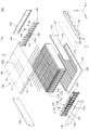
- FIG. 2 is an exploded top perspective view of the battery module according to the embodiment.
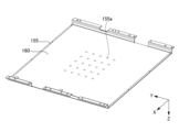
- FIG. 4 is a bottom perspective view of an upper plate according to the embodiment.
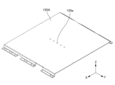
- FIG. 11 is a top perspective view of an upper plate according to a modified example.
- FIG. 1 is an exploded perspective view of the upper part of a battery module 100 according to an embodiment.
- FIG. 2 is a perspective view of the lower part of an upper plate 155 according to an embodiment.
- the X direction indicates the front-rear direction of the battery module 100.
- the Y direction is perpendicular to the X direction.
- the Y direction indicates the left-right direction of the battery module 100.
- the Z direction is perpendicular to both the X and Y directions.
- the Z direction indicates the up-down direction of the battery module 100.
- the arrows pointing to the X direction, the Y direction and the Z direction indicate the front, left and up directions of the battery module 100, respectively.
- the tip side of the arrow indicating the X direction will be referred to as the +X side
- the opposite side of the tip of the arrow indicating the X direction will be referred to as the -X side
- the tip side of the arrow indicating the Y direction will be referred to as the +Y side
- the opposite side of the tip of the arrow indicating the Y direction will be referred to as the -Y side
- the tip side of the arrow indicating the Z direction will be referred to as the +Z side
- the opposite side of the tip of the arrow indicating the Z direction will be referred to as the -Z side.
- the relationship between the X, Y, and Z directions and the front-rear, left-right, and up-down directions of the battery module 100 is not limited to the above example.
- the battery module 100 will be described with reference to Figure 1.
- the battery module 100 has a plurality of battery cells 110, a plurality of compression pads 120, a front voltage detection device 130, a rear voltage detection device 140, and a housing 150.
- the battery cells 110 are stacked in the Y direction.
- the compression pads 120 and the battery cells 110 are stacked alternately in the Y direction.
- Each compression pad 120 is disposed between adjacent battery cells 110 in the Y direction and on both sides of the battery cells 110 in the Y direction.
- the battery cells 110 and the compression pads 120 stacked alternately in the Y direction are referred to as a stack of battery cells 110.
- the dimension of each battery cell 110 in the X direction is the dimension in the longitudinal direction of each battery cell 110.
- the dimension of each battery cell 110 in the Z direction is the dimension in the lateral direction of each battery cell 110.
- the dimension of each battery cell 110 in the Y direction is the dimension in the thickness direction of each battery cell 110.
- the shape of each battery cell 110 is not limited to this example.
- Each battery cell 110 includes a battery element (not shown), an exterior material 112, a positive electrode tab 114, and a negative electrode tab 116.
- the battery element includes a plurality of positive electrodes and a plurality of negative electrodes (not shown) stacked alternately in the Y direction, and a separator (not shown) located between adjacent positive electrodes and negative electrodes in the Y direction.
- the exterior material 112 seals the battery element and an electrolyte (not shown).
- the positive electrode tab 114 is electrically connected to the positive electrode of the battery element.
- the positive electrode tab 114 is pulled out from one of both sides of the exterior material 112 in the X direction.
- the negative electrode tab 116 is electrically connected to the negative electrode of the battery element.
- the negative electrode tab 116 is pulled out from the other side of both sides of the exterior material 112 in the X direction.
- the structure of each battery cell 110 is not limited to this example.
- Each battery cell 110 may be an all-solid-state battery.
- an all-solid-state battery a solid electrolyte layer is provided in the portion corresponding to the separator.
- An all-solid-state battery does not contain an electrolyte.
- each battery cell 110 will be described as a battery cell containing an electrolyte.
- the battery cells 110 are electrically connected in a combination of series and parallel. Specifically, a cell group including at least two battery cells 110 adjacent to each other in the Y direction and connected in parallel is stacked in the Y direction and connected in series. At the front side of the stack of battery cells 110, a tab group 118 including the positive electrode tab 114 drawn from the battery cells 110 of one cell group connected in parallel and the negative electrode tab 116 drawn from the battery cells 110 of the other cell group connected in parallel are electrically connected to each other.
- the positive electrode tab 114 and the negative electrode tab 116 in the tab group 118 are joined to each other by, for example, laser welding.
- the tab group 118 is also located in the rear of the stack of battery cells 110.
- a plurality of cell groups are connected in series from the cell group located at one end side of the stack of battery cells 110 in the Y direction to the cell group located at the other end side of the stack of battery cells 110 in the Y direction.
- the tab group 118 located on the front side of the stack of battery cells 110 will be referred to as the front tab group 118
- the tab group 118 located on the rear side of the stack of battery cells 110 will be referred to as the rear tab group 118.
- the electrical connection of the multiple battery cells 110 is not limited to the above example.
- a stack of battery cells 110 may be formed by connecting single battery cells 110 in series.
- the front voltage detection device 130 detects the voltages of the multiple front tab groups 118.
- the front voltage detection device 130 includes a front protector 131, multiple front voltage detection terminals 132, multiple front voltage detection lines 133, a front connector 134, and a front bus bar 135.
- the front protector 131 covers the front of the stack of battery cells 110.
- the front protector 131 is, for example, an insulator such as resin.
- the front protector 131 defines a plurality of front openings 131a. Each of the plurality of front tab groups 118 is exposed forward through each of the plurality of front openings 131a.
- Each of the multiple front voltage detection terminals 132 is located in front of each of the multiple front tab groups 118.
- Each front voltage detection terminal 132 is, for example, a conductor such as metal.
- the rear surface of each front voltage detection terminal 132 and the front surface of each front tab group 118 are joined to each other by a joining method such as laser welding. Therefore, each front voltage detection terminal 132 and each front tab group 118 are electrically connected to each other. Therefore, the front voltage detection device 130 can detect the voltage of each front tab group 118 by each front voltage detection terminal 132.
- the multiple front voltage detection terminals 132 are held together by the front protector 131. Therefore, by placing the front protector 131 at an appropriate position relative to the stack of battery cells 110, each of the multiple front voltage detection terminals 132 can be placed at an appropriate position relative to each of the multiple front tab groups 118.
- each front voltage detection line 133 and each front voltage detection terminal 132 are electrically connected to each other.
- the other end of each front voltage detection line 133 and the front connector 134 are electrically connected to each other.
- the front voltage detection terminals 132 and the front connector 134 are electrically connected to each other via the front voltage detection lines 133.
- Each front voltage detection line 133 is routed between one end of each front voltage detection line 133 and the other end of each front voltage detection line 133 via the front protector 131.
- the front bus bar 135 is disposed at the right end of the front protector 131.
- the front bus bar 135 is electrically connected to the positive electrode tab 114 pulled forward from the battery cell 110 of the cell group located at the right end of the stack of battery cells 110.
- the front bus bar 135 functions as an external terminal for electrically connecting the battery module 100 to an external device such as another battery module.
- the rear voltage detection device 140 detects the voltages of the multiple rear tab groups 118.
- the rear voltage detection device 140 includes a rear protector 141, multiple rear voltage detection terminals 142, multiple rear voltage detection lines 143, a rear connector 144, and a rear bus bar 145.
- the rear protector 141 covers the rear of the stack of battery cells 110.
- the rear protector 141 is, for example, an insulator such as resin.
- the rear protector 141 defines a plurality of rear openings 141a. Each of the multiple rear tab groups 118 is exposed rearward through each of the multiple rear openings 141a.
- Each of the rear voltage detection terminals 142 is located behind each of the rear tab groups 118.
- Each rear voltage detection terminal 142 is, for example, a conductor such as metal.
- the front surface of each rear voltage detection terminal 142 and the rear surface of each rear tab group 118 are joined to each other by a joining method such as laser welding. Therefore, each rear voltage detection terminal 142 and each rear tab group 118 are electrically connected to each other. Therefore, the rear voltage detection device 140 can detect the voltage of each rear tab group 118 by each rear voltage detection terminal 142.
- the rear voltage detection terminals 142 are held together by the rear protector 141. Therefore, by placing the rear protector 141 at an appropriate position relative to the stack of battery cells 110, each of the rear voltage detection terminals 142 can be positioned at an appropriate position relative to each of the rear tab groups 118.
- each rear voltage detection line 143 and each rear voltage detection terminal 142 are electrically connected to each other.
- the other end of each rear voltage detection line 143 and the rear connector 144 are electrically connected to each other.
- the multiple rear voltage detection terminals 142 and the rear connector 144 are electrically connected to each other via the multiple rear voltage detection lines 143.
- Each rear voltage detection line 143 is routed between one end of each rear voltage detection line 143 and the other end of each rear voltage detection line 143 via the rear protector 141.
- the rear bus bar 145 is disposed at the left end of the rear protector 141.
- the rear bus bar 145 is electrically connected to the negative electrode tab 116 pulled out rearward from the battery cell 110 of the cell group located at the left end of the stack of battery cells 110.
- the rear bus bar 145 functions as an external terminal for electrically connecting the battery module 100 to an external device such as another battery module.
- the positive electrode tab 114 at the end of the multiple cell groups connected in series is pulled forward from the battery cell 110 of the cell group located at the right end side of the stack of battery cells 110
- the negative electrode tab 116 at the end of the multiple cell groups connected in series is pulled backward from the battery cell 110 of the cell group located at the left end side of the stack of battery cells 110.
- the front bus bar 135 is disposed on the right front side of the stack of battery cells 110
- the rear bus bar 145 is disposed on the left rear side of the stack of battery cells 110.
- the arrangement of the positive electrode tab 114 and the negative electrode tab 116 at the end of the multiple cell groups connected in series may differ depending on the number of battery cells 110 included in the stack of battery cells 110.
- the positive electrode tab 114 at the end of a group of cells connected in series may be pulled forward from the battery cell 110 of the cell group located at the right end of the stack of battery cells 110
- the negative electrode tab 116 at the end of a group of cells connected in series may be pulled forward from the battery cell 110 of the cell group located at the left end of the stack of battery cells 110.
- the bus bar electrically connected to the positive electrode tab 114 at the end of the group of cells connected in series is disposed on the right front side of the stack of battery cells 110
- the bus bar electrically connected to the negative electrode tab 116 at the end of the group of cells connected in series is disposed on the left front side of the stack of battery cells 110.
- the housing 150 houses a stack of battery cells 110.
- the housing 150 includes a front plate 151, a rear plate 152, a left plate 153, a right plate 154, an upper plate 155, and a lower plate 156.
- Each plate is, for example, a metal plate such as an aluminum plate.
- the front plate 151 covers the +X side of the stack of battery cells 110 and the +X side of the front voltage detection device 130.
- the rear plate 152 covers the -X side of the stack of battery cells 110 and the -X side of the rear voltage detection device 140.
- the left plate 153 covers the +Y side of the stack of battery cells 110.
- the right plate 154 covers the -Y side of the stack of battery cells 110.
- the upper plate 155 covers the +Z side of the stack of battery cells 110.
- the lower plate 156 covers the -Z side of the stack of battery cells 110.
- a thermally conductive adhesive 170 is disposed between the upper surface of the lower plate 156 and the lower surface of the stack of battery cells 110. Therefore, heat generated from the stack of battery cells 110 can be released toward the bottom of the battery module 100 through the thermally conductive adhesive 170.
- Abnormal heat generation in the battery cell 110 occurs, for example, when the electrodes of the battery cell 110, such as the positive and negative electrodes, are short-circuited due to factors such as vibration of the battery module 100 or impact on the battery module 100. Abnormal heat generation in the battery cell 110 is likely to occur in the central parts of the X and Y directions of the stack of the battery cells 110. This is because the central parts of the X and Y directions of the stack of the battery cells 110 are more susceptible to heat than the peripheral parts of the central parts of the X and Y directions of the stack of the battery cells 110. Therefore, gas generated from the battery cell 110 when abnormal heat generation occurs in the battery cell 110 is likely to occur in the central parts of the X and Y directions of the stack of the battery cells 110.
- the upper plate 155 defines a plurality of holes 155a.
- the plurality of holes 155a are provided to exhaust gas generated from the battery cells 110 when abnormal heat generation occurs in the battery cells 110.
- the plurality of holes 155a are located above the stack of battery cells 110. Therefore, gas generated from the battery cells 110 can be more easily exhausted through the holes 155a compared to a case in which the holes 155a are located below, in front, behind, left, or right of the stack of battery cells 110.
- the housing 150 is sealed from the space outside the housing 150 except for the multiple holes 155a. Therefore, the airtightness of the housing 150 can be improved compared to a case where gas generated from the battery cell 110 can be discharged from the housing 150 through a part other than the multiple holes 155a.
- the holes 155a are arranged in multiple rows and multiple columns in the X and Y directions, respectively, in the central portion of the upper plate 155 in the X and Y directions, as viewed from the Z direction. Therefore, compared to the case where the holes 155a are uniformly arranged over the entire upper plate 155 as viewed from the Z direction, it is easier to selectively discharge high-temperature gas generated from the battery cell 110 from the central portion of the upper plate 155 in the X and Y directions.
- 25 holes 155a are arranged in five rows and five columns in the X and Y directions, respectively, as viewed from the Z direction.
- the pitch in the Y direction of the five holes 155a in each row is equal to the pitch in the X direction of the five holes 155a in each column.
- No holes 155a are provided in the portion surrounding the central portion of the upper plate 155 in the X and Y directions as viewed from the Z direction.
- the number and arrangement of the multiple holes 155a are not limited to the example shown in Figures 1 and 2.
- FIG. 1 illustrates a first virtual line L1, a second virtual line L2, a third virtual line L3, and a fourth virtual line L4.
- the first virtual line L1 passes through the holes 155a located in the frontmost row of the multiple holes 155a.
- the second virtual line L2 passes through the holes 155a located in the rearmost row of the multiple holes 155a.
- the third virtual line L3 passes through the holes 155a located in the leftmost column of the multiple holes 155a.
- the fourth virtual line L4 passes through the holes 155a located in the rightmost column of the multiple holes 155a.
- the distance in the X direction between the first virtual line L1 and the front end of the upper plate 155 is, for example, 20% to 45% of the dimension in the X direction of the upper plate 155.
- the distance in the X direction between the second virtual line L2 and the rear end of the upper plate 155 is, for example, 20% to 45% of the dimension in the X direction of the upper plate 155.
- the distance in the Y direction between the third virtual line L3 and the left end of the upper plate 155 is, for example, 20% to 45% of the dimension in the Y direction of the upper plate 155.
- the distance in the Y direction between the fourth virtual line L4 and the right end of the upper plate 155 is, for example, 20% to 45% of the dimension in the Y direction of the upper plate 155.
- the portion of the upper plate 155 between the first virtual line L1 and the front end overlaps with the front tab group 118 in the Z direction near the front end of the upper plate 155. Therefore, no holes 155a are provided in the portion of the upper plate 155 that overlaps with the front tab group 118 in the Z direction. Therefore, the ratio of holes 155a in the central portion in the X direction to the portion of the upper plate 155 that overlaps with the front tab group 118 in the Z direction is greater than the ratio of holes 155a in the portion of the upper plate 155 that overlaps with the front tab group 118 in the Z direction.
- the portion of the upper plate 155 between the second virtual line L2 and the rear end overlaps with the rear tab groups 118 in the Z direction near the rear end of the upper plate 155. Therefore, no holes 155a are provided in the portion of the upper plate 155 that overlaps with the rear tab groups 118 in the Z direction. Therefore, the ratio of holes 155a in the central portion in the X direction to the portion of the upper plate 155 that overlaps with the rear tab groups 118 in the Z direction is greater than the ratio of holes 155a in the portion of the upper plate 155 that overlaps with the rear tab groups 118 in the Z direction.
- the portion of the upper plate 155 between the third virtual line L3 and the left end overlaps in the Z direction with at least one battery cell 110 on the left end side in the Y direction near the left end of the upper plate 155. Therefore, no hole 155a is provided in the portion overlapping in the Z direction with at least one battery cell 110 on the left end side of the upper plate 155. Therefore, the ratio of holes 155a in the central portion in the Y direction to the portion overlapping in the Z direction with at least one battery cell 110 on the left end side of the upper plate 155 is greater than the ratio of holes 155a in the portion overlapping in the Z direction with at least one battery cell 110 on the left end side of the upper plate 155.
- the portion of the upper plate 155 between the fourth virtual line L4 and the right end overlaps in the Z direction with at least one battery cell 110 on the right end side in the Y direction near the right end of the upper plate 155. Therefore, no hole 155a is provided in the portion overlapping in the Z direction with at least one battery cell 110 on the right end side of the upper plate 155. Therefore, the ratio of holes 155a in the central portion in the Y direction to the portion overlapping in the Z direction with at least one battery cell 110 on the right end side of the upper plate 155 is greater than the ratio of holes 155a in the portion overlapping in the Z direction with at least one battery cell 110 on the right end side of the upper plate 155.
- the upper plate 155 may have holes other than the holes 155a arranged in the central portion in the X direction and the Y direction in the portion between the first virtual line L1 and the front end.
- the ratio of the holes 155a in the central portion in the X direction to the portion overlapping the front tab groups 118 of the upper plate 155 in the Z direction is greater than the ratio of the other holes in the portion overlapping the front tab groups 118 of the upper plate 155 in the Z direction, depending on the size or arrangement of the other holes.
- the portion between the second imaginary line L2 and the rear end of the upper plate 155, the portion between the third imaginary line L3 and the left end of the upper plate 155, and the portion between the fourth imaginary line L4 and the right end of the upper plate 155 may also have holes other than the multiple holes 155a arranged in the central portion of the upper plate 155 in the X direction and Y direction, similar to the portion between the first imaginary line L1 and the front end of the upper plate 155.
- the holes 155a in each row among the multiple holes 155a may be arranged in the Y direction at a pitch N times the pitch of the multiple battery cells 110 in the Y direction (N is an integer equal to or greater than 1).
- N is an integer equal to or greater than 1.
- the holes 155a in each row and the different battery cells 110 may overlap each other in the Z direction.
- the holes 155a in each row and the different battery cells 110 overlap each other in the Z direction, the holes 155a are located directly above the different battery cells 110 in the Z direction.
- the center positions in the Y direction of each of the different battery cells 110 and the center positions in the Y direction of the holes 155a located directly above each of the different battery cells 110 are aligned in the Y direction. Therefore, compared to when the hole 155a is located at a position shifted in the Y direction from the position directly above the battery cell 110 in the Z direction, it is possible to make it more difficult for gas generated from the battery cell 110 to pass near other battery cells 110.
- each hole 155a when viewed from the Z direction, has a circular shape.
- the shape of each hole 155a is not limited to the example shown in Figures 1 and 2.
- the shapes of at least some of the holes 155a may be different from each other.
- the Y-direction dimension of each hole 155a may be equal to or smaller than the Y-direction dimension of each battery cell 110.
- each hole 155a is less likely to overlap with multiple battery cells 110 in the Z direction, and gas generated from a battery cell 110 is less likely to pass near other battery cells 110, compared to when the Y-direction dimension of each hole 155a is larger than the Y-direction dimension of each battery cell 110.
- the holes 155a have the same dimensions as viewed in the Z direction. However, the dimensions of at least some of the holes 155a may differ from each other. For example, the dimensions of the holes 155a may decrease as they move away from the center of the upper plate 155 in the X and Y directions as viewed in the Z direction. For example, the holes 155a may be provided with dimensions that decrease as they move forward from the center of the upper plate 155 in the X and Y directions. In this example, the ratio of holes 155a in the central part in the X direction to the part overlapping the front tab groups 118 of the upper plate 155 in the Z direction can be made higher than the ratio of holes 155a in the part overlapping the front tab groups 118 of the upper plate 155 in the Z direction. Similarly, the holes 155a may be provided with dimensions that decrease as they move rearward, leftward, or rightward from the center of the upper plate 155 in the X and Y directions.
- the battery module 100 further includes a covering member 160.
- the covering member 160 is provided over almost the entire lower surface of the upper plate 155.
- the covering member 160 covers a plurality of holes 155a. Thus, the lower end of each hole 155a is blocked by the covering member 160.
- the covering member 160 is an insulating sheet such as a resin sheet. Thus, the covering member 160 has electrical insulation properties. Therefore, the covering member 160 can electrically insulate the upper surface of the stack of battery cells 110 from the lower surface of the upper plate 155.
- the melting point of the covering member 160 is higher than the temperature around the covering member 160 when the battery cell 110 is operating normally, and is lower than the temperature around the covering member 160 when the battery cell 110 is abnormally heated. Therefore, when the battery cell 110 is operating normally, the covering member 160 does not melt and closes the lower end of each hole 155a. Therefore, compared to when the covering member 160 is not provided, the airtightness of the housing 150 when the battery cell 110 is operating normally can be improved. In contrast, when the battery cell 110 is abnormally heated, the covering member 160 melts due to the heat generated from the battery cell 110, opening the lower end of each hole 155a. Therefore, when the battery cell 110 is abnormally heated, gas generated from the battery cell 110 can be discharged through each hole 155a. This makes it possible to improve the airtightness of the housing 150 when the battery cell 110 is operating normally, while also allowing gas to escape from the housing 150 when the battery cell 110 generates abnormal heat.
- each hole 155a of the covering member 160 is not limited to the above example.
- the covering member 160 may not break due to the pressure in the internal space of the container 150 when the battery cell 110 is operating normally, but may break due to the pressure of the gas generated from the battery cell 110 when the battery cell 110 is abnormally heated. Even in this example, the airtightness of the container 150 when the battery cell 110 is operating normally can be improved compared to when the covering member 160 is not provided.
- the covering member 160 is broken by the gas generated from the battery cell 110, and the lower end of each hole 155a is opened. Therefore, when the battery cell 110 is abnormally heated, the gas generated from the battery cell 110 can be discharged through each hole 155a.
- FIG. 3 is an upper perspective view of the modified upper plate 155A.
- the modified upper plate 155A is similar to the upper plate 155 according to the embodiment, except for the following points.
- the upper plate 155A according to the modified example defines a plurality of holes 155a arranged in a row in the Y direction in the central portion of the upper plate 155A in the X direction. Therefore, even in the example shown in FIG. 3, the ratio of holes 155a in the central portion in the X direction to the portion of the upper plate 155A overlapping with the plurality of front tab groups 118 in the Z direction is greater than the ratio of holes 155a in the portion of the upper plate 155A overlapping with the plurality of front tab groups 118 in the Z direction.
- the ratio of holes 155a in the central portion in the X direction to the portion of the upper plate 155A overlapping with the multiple rear tab groups 118 in the Z direction is greater than the ratio of holes 155a in the portion of the upper plate 155A overlapping with the multiple rear tab groups 118 in the Z direction.
- the multiple holes 155a arranged in a row in the Y direction may not be located in the center of the upper plate 155A in the X direction, but may be offset in the X direction from the center of the upper plate 155A in the X direction.
Landscapes
- Battery Mounting, Suspending (AREA)
Abstract
L'invention concerne un module de batterie (100) qui comprend : une pluralité d'éléments de batterie (110) qui sont empilés dans la direction Y et qui présentent chacun une languette d'électrode positive (114) ou une languette d'électrode négative (116) positionnée sur un côté de direction X ; et un corps de réception (150) qui comporte une plaque supérieure (155) pour recouvrir des parties latérales de direction Z de la pluralité d'éléments de batterie (110) et qui reçoit la pluralité d'éléments de batterie (110). La plaque supérieure (155) définit une pluralité de trous (155a) permettant d'évacuer le gaz évacué à partir des éléments de batterie (110). Par rapport à une partie de la plaque supérieure (155) chevauchant la languette d'électrode positive (114) ou la languette d'électrode négative (116) dans la direction Z, le rapport des trous (155a) situés dans une partie centrale dans la direction X est supérieur au rapport des trous (155a) situés dans la partie de la plaque supérieure (155) chevauchant la languette d'électrode positive (114) ou la languette d'électrode négative (116) dans la direction Z.
Applications Claiming Priority (2)
| Application Number | Priority Date | Filing Date | Title |
|---|---|---|---|
| JP2023-094021 | 2023-06-07 | ||
| JP2023094021 | 2023-06-07 |
Publications (1)
| Publication Number | Publication Date |
|---|---|
| WO2024253014A1 true WO2024253014A1 (fr) | 2024-12-12 |
Family
ID=93795946
Family Applications (1)
| Application Number | Title | Priority Date | Filing Date |
|---|---|---|---|
| PCT/JP2024/019842 Ceased WO2024253014A1 (fr) | 2023-06-07 | 2024-05-30 | Module de batterie |
Country Status (1)
| Country | Link |
|---|---|
| WO (1) | WO2024253014A1 (fr) |
Citations (3)
| Publication number | Priority date | Publication date | Assignee | Title |
|---|---|---|---|---|
| WO2020153017A1 (fr) * | 2019-01-25 | 2020-07-30 | 三洋電機株式会社 | Bloc-batterie |
| WO2023282609A1 (fr) * | 2021-07-07 | 2023-01-12 | 주식회사 엘지에너지솔루션 | Module de batterie et batterie le comprenant |
| WO2023282712A1 (fr) * | 2021-07-09 | 2023-01-12 | 주식회사 엘지에너지솔루션 | Module de batterie à sécurité renforcée |
-
2024
- 2024-05-30 WO PCT/JP2024/019842 patent/WO2024253014A1/fr not_active Ceased
Patent Citations (3)
| Publication number | Priority date | Publication date | Assignee | Title |
|---|---|---|---|---|
| WO2020153017A1 (fr) * | 2019-01-25 | 2020-07-30 | 三洋電機株式会社 | Bloc-batterie |
| WO2023282609A1 (fr) * | 2021-07-07 | 2023-01-12 | 주식회사 엘지에너지솔루션 | Module de batterie et batterie le comprenant |
| WO2023282712A1 (fr) * | 2021-07-09 | 2023-01-12 | 주식회사 엘지에너지솔루션 | Module de batterie à sécurité renforcée |
Similar Documents
| Publication | Publication Date | Title |
|---|---|---|
| US11177530B2 (en) | Battery pack | |
| EP3664187B1 (fr) | Ensemble de cellules de batterie cylindriques à utilisation d'espace et sécurité améliorées et module de batterie le comprenant | |
| CN113826270B (zh) | 电池组、电子装置及车辆 | |
| CN102246330A (zh) | 电池组件和使用了该电池组件的电池组件集合体 | |
| CN106549124A (zh) | 高压电池子模块 | |
| WO2012093452A1 (fr) | Pack de batteries | |
| WO2024253014A1 (fr) | Module de batterie | |
| JP7636083B2 (ja) | 電池モジュールおよびこれを含む電池パック | |
| JP2025166354A (ja) | 電池モジュール | |
| WO2025211328A1 (fr) | Module de batterie | |
| WO2026053983A1 (fr) | Module de batterie | |
| JP2025063436A (ja) | 電池モジュール | |
| JP2025130920A (ja) | 電池モジュール | |
| JP7667124B2 (ja) | 電池モジュール | |
| JP2025130919A (ja) | 電池パック | |
| WO2025074833A1 (fr) | Module de batterie | |
| JP2025130921A (ja) | 電池モジュール | |
| WO2025216157A1 (fr) | Module de batterie | |
| WO2025182675A1 (fr) | Dispositif de détection de tension et module de batterie | |
| JP2025130923A (ja) | 電圧検出装置及び電池モジュール | |
| JP2025136878A (ja) | 電池モジュール | |
| JP2025136879A (ja) | 電池モジュール | |
| WO2025004591A1 (fr) | Module de batterie | |
| CN121889931A (zh) | 电池组、电池组盖以及包括该电池组的车辆 | |
| CN120604388A (zh) | 电池模块、电池组和包括该电池组的车辆 |
Legal Events
| Date | Code | Title | Description |
|---|---|---|---|
| 121 | Ep: the epo has been informed by wipo that ep was designated in this application |
Ref document number: 24819245 Country of ref document: EP Kind code of ref document: A1 |
|
| NENP | Non-entry into the national phase |
Ref country code: DE |