WO2024253020A1 - Control device, temperature adjustment system, temperature adjustment device control method, and program - Google Patents
Control device, temperature adjustment system, temperature adjustment device control method, and program Download PDFInfo
- Publication number
- WO2024253020A1 WO2024253020A1 PCT/JP2024/019918 JP2024019918W WO2024253020A1 WO 2024253020 A1 WO2024253020 A1 WO 2024253020A1 JP 2024019918 W JP2024019918 W JP 2024019918W WO 2024253020 A1 WO2024253020 A1 WO 2024253020A1
- Authority
- WO
- WIPO (PCT)
- Prior art keywords
- temperature
- control
- temperature sensor
- compressor
- control device
- Prior art date
- Legal status (The legal status is an assumption and is not a legal conclusion. Google has not performed a legal analysis and makes no representation as to the accuracy of the status listed.)
- Ceased
Links
Images


Classifications
-
- F—MECHANICAL ENGINEERING; LIGHTING; HEATING; WEAPONS; BLASTING
- F24—HEATING; RANGES; VENTILATING
- F24F—AIR-CONDITIONING; AIR-HUMIDIFICATION; VENTILATION; USE OF AIR CURRENTS FOR SCREENING
- F24F11/00—Control or safety arrangements
- F24F11/70—Control systems characterised by their outputs; Constructional details thereof
- F24F11/80—Control systems characterised by their outputs; Constructional details thereof for controlling the temperature of the supplied air
- F24F11/86—Control systems characterised by their outputs; Constructional details thereof for controlling the temperature of the supplied air by controlling compressors within refrigeration or heat pump circuits
-
- F—MECHANICAL ENGINEERING; LIGHTING; HEATING; WEAPONS; BLASTING
- F24—HEATING; RANGES; VENTILATING
- F24F—AIR-CONDITIONING; AIR-HUMIDIFICATION; VENTILATION; USE OF AIR CURRENTS FOR SCREENING
- F24F11/00—Control or safety arrangements
- F24F11/30—Control or safety arrangements for purposes related to the operation of the system, e.g. for safety or monitoring
- F24F11/46—Improving electric energy efficiency or saving
-
- F—MECHANICAL ENGINEERING; LIGHTING; HEATING; WEAPONS; BLASTING
- F24—HEATING; RANGES; VENTILATING
- F24F—AIR-CONDITIONING; AIR-HUMIDIFICATION; VENTILATION; USE OF AIR CURRENTS FOR SCREENING
- F24F11/00—Control or safety arrangements
- F24F11/62—Control or safety arrangements characterised by the type of control or by internal processing, e.g. using fuzzy logic, adaptive control or estimation of values
- F24F11/63—Electronic processing
- F24F11/65—Electronic processing for selecting an operating mode
- F24F11/67—Switching between heating and cooling modes
-
- F—MECHANICAL ENGINEERING; LIGHTING; HEATING; WEAPONS; BLASTING
- F24—HEATING; RANGES; VENTILATING
- F24F—AIR-CONDITIONING; AIR-HUMIDIFICATION; VENTILATION; USE OF AIR CURRENTS FOR SCREENING
- F24F2110/00—Control inputs relating to air properties
- F24F2110/10—Temperature
-
- F—MECHANICAL ENGINEERING; LIGHTING; HEATING; WEAPONS; BLASTING
- F24—HEATING; RANGES; VENTILATING
- F24F—AIR-CONDITIONING; AIR-HUMIDIFICATION; VENTILATION; USE OF AIR CURRENTS FOR SCREENING
- F24F2110/00—Control inputs relating to air properties
- F24F2110/10—Temperature
- F24F2110/12—Temperature of the outside air
-
- F—MECHANICAL ENGINEERING; LIGHTING; HEATING; WEAPONS; BLASTING
- F24—HEATING; RANGES; VENTILATING
- F24F—AIR-CONDITIONING; AIR-HUMIDIFICATION; VENTILATION; USE OF AIR CURRENTS FOR SCREENING
- F24F2110/00—Control inputs relating to air properties
- F24F2110/50—Air quality properties
- F24F2110/65—Concentration of specific substances or contaminants
Definitions
- the present invention relates to a control device for controlling a temperature adjustment device, a temperature adjustment system including such a control device and a temperature adjustment device, a control method for a temperature adjustment device, and a program for causing a processor to execute a procedure for controlling the temperature adjustment device.
- thermo adjustment devices that adjust the temperature of a specific area.
- a refrigerant sealed inside a pipe is compressed and expanded using a compressor and a pressure reducer, and the heat on the heat absorption side is transferred to the heat exhaust side by transferring the heat of the refrigerant to the heat exhaust side through two heat exchangers arranged on the heat absorption side and the heat of the refrigerant is discarded on the heat exhaust side.
- the temperature adjustment device functions as an air conditioner, refrigeration, or freezer, and if the heat exhaust side is inside a room or a cabinet, the temperature adjustment device functions as a heater, heat retention, or heating device.
- Patent Document 1 proposes a technique for reducing energy consumption by devising on/off control of compressors in refrigerant systems, refrigeration and heating systems.
- Patent Document 1 does not necessarily achieve a sufficient reduction rate in energy consumption.
- the present invention has been made against this background, and aims to appropriately control the operation of a compressor in a temperature control device to reduce energy consumption while minimizing the impact on the temperature control function, and also to make it possible to easily add such a control function to an existing temperature control device.
- the control device of the present invention includes a compressor, a heat exchanger, an intake section, an exhaust section, a temperature sensor, and a control section, and controls a temperature adjustment device in which gas sucked in through the intake section is subjected to heat exchange in the heat exchanger and exhausted through the exhaust section, and the control section controls the operation of the compressor based on a signal supplied from the temperature sensor.
- the control device includes an intake temperature sensor disposed in the intake section and detecting the temperature of the gas sucked in, an exhaust temperature sensor disposed in the exhaust section and detecting the temperature of the gas exhausted, an operation detection section that detects whether the temperature adjustment device is operating, and a control signal output section that is capable of performing a first control to output a first control signal to the control section to cause the control section to control the compressor to stop or operate at a low speed when the temperature detected by the intake temperature sensor becomes equal to or lower than a predetermined first target temperature after a predetermined time has elapsed since the start of operation of the temperature adjustment device, and to stop outputting the first control signal to the control section when the temperature detected by the exhaust temperature sensor becomes equal to or higher than a second target temperature determined based on the first target temperature.
- a heat exchanger temperature sensor is provided that is disposed in the heat exchanger and detects the temperature of the heat exchanger, and the control signal output unit stores the detected temperature of the heat exchanger temperature sensor when the detected temperature of the intake air temperature sensor becomes equal to or lower than the first target temperature after the predetermined time has elapsed since the temperature adjustment device started operating in the first control, and thereafter, when the detected temperature of the heat exchanger temperature sensor rises by a predetermined first threshold value or more compared to the stored detected temperature and the detected temperature of the exhaust air temperature sensor becomes equal to or higher than the second target temperature, the control signal output unit stops outputting the first control signal to the control unit.
- the control signal output unit switches between cooling mode and heating mode depending on whether the detected temperature of the exhaust temperature sensor at the time when the predetermined time has elapsed since the start of operation of the temperature adjustment device is equal to or higher than a predetermined second threshold, and performs the first control in the cooling mode, and in the heating mode, outputs the first control signal to the control unit when the detected temperature of the intake air temperature sensor is equal to or higher than a predetermined third target temperature after the predetermined time has elapsed since the start of operation of the temperature adjustment device, and then performs a second control to stop outputting the first control signal to the control unit when the detected temperature of the exhaust temperature sensor is equal to or lower than a fourth target temperature determined based on the third target temperature.
- the control signal output unit switches between cooling mode and heating mode depending on whether the detected temperature of the exhaust temperature sensor at the time when the predetermined time has elapsed since the start of operation of the temperature adjustment device is equal to or higher than a predetermined second threshold, and performs the first control in the cooling mode, and in the heating mode, if the detected temperature of the intake air temperature sensor becomes equal to or higher than a predetermined third target temperature after the predetermined time has elapsed since the start of operation of the temperature adjustment device, outputs the first control signal to the control unit and stores the detected temperature of the heat exchanger temperature sensor, and then performs a second control to stop outputting the first control signal to the control unit when the detected temperature of the heat exchanger temperature sensor drops by equal to or higher than the predetermined second threshold compared to the stored detected temperature and the detected temperature of the exhaust temperature sensor becomes equal to or lower than a fourth target temperature determined based on the third target temperature.
- the operation of the heating mode be switchable between a normal heating mode and a ceiling-mounted heating mode in which the third target temperature is higher than in the normal heating mode and the fourth target temperature is the same.
- the temperature adjustment device may be driven by an AC power source and include a power supply circuit for supplying DC power to a remote controller of the temperature adjustment device via a terminal, and the control device may be driven by a DC power source and include a connection portion for electrically connecting to the terminal of the temperature adjustment device.
- the temperature adjustment system of the present invention includes any one of the control devices described above and the temperature adjustment device described above, and the temperature adjustment device includes a power supply circuit that is driven by an AC power source and supplies DC power to a remote controller of the temperature adjustment device via a terminal, and the control device is driven by a DC power source and receives power from the terminal of the temperature adjustment device.
- control signal output unit when the control signal output unit stops outputting the first control signal to the control unit, it is preferable that the control signal output unit outputs a second control signal to the control unit to cause the control unit to control the compressor to operate at a rated speed. Furthermore, after the control signal output unit outputs the second control signal to the control unit, it is preferable that the control signal output unit stops outputting the second control signal to the control unit before next outputting the first control signal to the control unit.
- the present invention as described above can be implemented in any form, such as the control device or temperature adjustment system described above, a system in which the functions of each device are distributed to multiple devices and work together, a method, a program, or a recording medium on which a program is recorded.
- the operation of the compressor in the temperature adjustment device can be appropriately controlled, reducing the impact on the temperature adjustment function and reducing energy consumption. It is also possible to easily add such control functions to existing temperature adjustment devices.
- FIG. 1 is a diagram showing a schematic configuration of a control device 100 according to a first embodiment of the present invention and an air conditioner 400 which is an example of a temperature adjustment device that is a target of control by the control device 100.
- FIG. FIG. 2 is a diagram showing the hardware configuration of the control device 100 in more detail.
- 5A to 5C are diagrams showing examples of screens displayed on an operation panel 120.
- 4 is a flowchart of a process executed by a CPU 101 of the control device 100.
- 5 is a flowchart showing a continuation of the process shown in FIG. 4 .
- FIG. 5 is a diagram illustrating a modification of the process shown in FIG. 4 .
- FIG. 1 is a diagram corresponding to FIG.
- FIG. 1 diagrammatically illustrating the configuration of a control device 100 according to a second embodiment of the present invention and an air conditioner 400 which is an example of a temperature adjustment device that is an object of control by the control device 100.
- 10 is a diagram corresponding to FIG. 2 and illustrating in more detail the hardware configuration of the control device 100 according to the second embodiment.
- 10A and 10B are diagrams showing examples of screens displayed on an operation panel 120 according to the second embodiment, and correspond to FIG. 3 .
- 10A and 10B are diagrams showing examples of screens displayed on operation panel 120 in a modified example, and correspond to FIG. 9 .
- FIG. 1 shows a schematic configuration of a control device 100 according to a first embodiment of the present invention and an air conditioner 400 which is an example of a temperature adjustment device to be controlled by the control device 100.
- An air conditioning system (hereinafter referred to as "air conditioner") 400 shown in Fig. 1 includes an indoor unit 200 and an outdoor unit 300.
- the indoor unit 200 is usually placed inside a wall 500 of a building, indoors, where the room temperature (temperature of air, which is a gas) should be adjusted.
- the outdoor unit 300 is placed outdoors.
- Fig. 1 mainly shows the configuration of the air conditioner 400 related to temperature adjustment.
- the control device 100 is a device that is additionally installed in the air conditioner 400 and has a function of controlling the operation of a compressor 311 of the air conditioner 400 using an algorithm different from that of the control unit 220 on the air conditioner 400 side.
- the air conditioner 400 includes a refrigerant circuit 410 that spans the indoor unit 200 and the outdoor unit 300.
- the refrigerant circuit 410 is a closed circuit filled with refrigerant, and can be configured, for example, so that the refrigerant circulates to perform a vapor compression refrigeration cycle.
- the refrigerant circuit 410 includes a compressor 311, a four-way valve (four-way switching valve) 312, an outdoor heat exchanger 313, and an expansion valve (pressure reducing valve) 314 on the outdoor unit 300 side, and an indoor heat exchanger 211 on the indoor unit 200 side, which are connected by a refrigerant pipe 310 with the refrigerant sealed inside.
- the compressor 311 has a discharge side connected to a first port P1 of the four-way valve 312, and a suction side connected to a third port P3 of the four-way valve 312.
- the four-way valve 312 connects the first port P1 to the second port P2, and also connects the third port P3 to the fourth port P4.
- the four-way valve 312 connects the first port P1 to the fourth port P4, and also connects the second port P2 to the third port P3, as shown by the imaginary lines in the figure. This forms a path through which the refrigerant discharged from the compressor 311 passes through the indoor heat exchanger 211, the expansion valve 314, and the outdoor heat exchanger 313 in this order, and returns to the suction side of the compressor 311.
- the compressor 311 compresses and discharges the sucked refrigerant.
- Any type of compressor such as a fixed capacity type or a variable capacity type, can be used.
- heat is exchanged between the refrigerant and outdoor air taken in from a ventilation opening 316 by an outdoor fan 321 as indicated by an arrow A.
- the air after the heat exchange is discharged from the ventilation opening 316 as indicated by an arrow B.
- the expansion valve 314 reduces the pressure of the high-pressure liquid refrigerant to a state where it is easy to evaporate, and turns it into a low-pressure liquid refrigerant.
- Any type of expansion valve can be used, such as a capillary tube, a thermostatic expansion valve, or an electronic expansion valve.
- the indoor heat exchanger 211 on the indoor unit 200 side heat is exchanged between the indoor air taken in from the intake port 214 by the indoor fan 212 and the refrigerant.
- the indoor fan 212 for example, rotates an impeller tilted forward in the direction of rotation to draw in air from the intake port 214 as intake C, and releases the air after heat exchange from the exhaust port 215 as exhaust D. In this way, indoor air is taken in by the indoor unit 200, and the air with its temperature, etc., adjusted is expelled into the room.
- the outdoor heat exchanger 313 becomes a condenser (heat radiator) and the indoor heat exchanger 211 becomes an evaporator, performing a refrigeration cycle.
- the refrigerant discharged from the compressor 311 flows to the outdoor heat exchanger 313 and radiates heat to the outdoor air.
- the refrigerant that has radiated heat then expands (reduced in pressure) as it passes through the expansion valve 314 and flows to the indoor heat exchanger 211.
- the indoor heat exchanger 211 the refrigerant absorbs heat from the indoor air and evaporates, and the cooled indoor air is supplied to the room.
- the evaporated refrigerant is sucked into the compressor 311 and compressed.
- the indoor heat exchanger 211 becomes a condenser (heat radiator) and the outdoor heat exchanger 313 becomes an evaporator, performing a refrigeration cycle.
- the refrigerant discharged from the compressor 311 flows into the indoor heat exchanger 211 and radiates heat to the indoor air. This supplies heated indoor air to the room.
- the refrigerant that radiates heat expands (is reduced in pressure) when passing through the expansion valve 314.
- the refrigerant that expands in the expansion valve 314 flows into the outdoor heat exchanger 313 and absorbs heat from the outdoor air to evaporate. The evaporated refrigerant is sucked into the compressor 311 and compressed.
- the operation of each of the above-mentioned parts is controlled by a control unit 220 provided on the indoor unit 200 side.
- the control unit 220 may be a computer equipped with a processor and memory, a dedicated control circuit, or a combination of these.
- the control unit 220 controls the operation of each part of the air conditioner 400 by sending control signals C1 to Cn to each part of the air conditioner 400 based on detection signals from sensors provided in each part of the air conditioner 400, including the indoor unit 200 side and the outdoor unit 300 side. Signal lines (not shown) for transmitting these control signals are wired between the indoor unit 200 and the outdoor unit 300.
- control signal C1 of the compressor 311, the control signal C2 of the outdoor fan 321, the control signal C3 of the four-way valve 312, the control signal C4 of the expansion valve 314, and the control signal C5 of the indoor fan 212 are shown as representatives, but are not limited to these.
- the temperature sensor 213 that is provided near the intake port 214 and detects the temperature of the intake air C is shown as a sensor related to the features of this embodiment, but is not limited to this.
- the wiring is done so that the detection signal Tin of the temperature sensor 213 is input to the Tin terminal of the control unit 220.
- the wiring is done so that the detection signal Tin of the temperature sensor 213 is input to the control device 100, and the control signal Tinx output by the control device 100 is input to the Tin terminal of the control unit 220. The significance of this wiring will be explained in detail later.
- the air conditioner 400 is also configured to be driven by power supplied from an AC power source 510 provided in the building to a power supply circuit 230 provided in the indoor unit 200.
- the power supply circuit 230 appropriately adjusts the voltage and current of the electricity supplied from the AC power source 510, converting it to DC as necessary, and supplies the necessary power to each part of the indoor unit 200.
- the indoor unit 200 and outdoor unit 300 are also connected by a power line (not shown), and the power supply circuit 230 also supplies the necessary power to each part on the outdoor unit 300 side.
- the air conditioner 400 is also provided with a remote controller 240, which is connected to the control unit 220 via a signal line 222.
- a remote controller 240 By operating the remote controller 240, the user can operate the air conditioner 400 by issuing various operational instructions to the control unit 220, such as turning the power on and off, switching between cooling and heating, and setting the set temperatures for cooling and heating.
- the remote controller 240 is driven by a DC power source.
- the power supply circuit 230 supplies DC power to a DC power supply terminal 231 of the indoor unit 200. By connecting the power supply line 241 of the remote controller 240 to this DC power supply terminal 231, the remote controller 240 can receive power from the indoor unit 200 and operate.
- the control device 100 has the function of inputting the detection signals T1 to T3 from the intake temperature sensor 111, the exhaust temperature sensor 112, and the heat exchanger temperature sensor 113, inputting the detection signal E1 indicating the operating state of the power supply circuit 230, and controlling the operation of the compressor 311 provided in the air conditioning device 400 in accordance with these signals.
- the intake air temperature sensor 111 is disposed in an intake section through which the intake air C passes, near the intake port 214 of the indoor unit 200, and is a sensor that detects the temperature of the intake air C.
- the exhaust air temperature sensor 112 is disposed in an exhaust section through which the exhaust air D passes, near the exhaust port 215 of the indoor unit 200, and is a sensor that detects the temperature of the exhaust air D.
- the heat exchanger temperature sensor 113 is a sensor that is provided near or inside the indoor heat exchanger 211 or in contact with the indoor heat exchanger 211 , and detects the temperature of the indoor heat exchanger 211 .
- any type of sensor such as a thermistor, a thermocouple, or an infrared sensor, can be used, whether contact or non-contact.
- a current sensor 114 is installed in the circuit of the power supply circuit 230 that supplies power to each part of the refrigerant circuit 410, to detect whether the power supply circuit 230 is supplying power for cooling or heating operation, i.e., whether cooling or heating is in operation. Conversely, the current sensor 114 is installed at a location in the power supply circuit 230 where such detection is possible.
- the current sensor 114 can be, for example, a magnetic type, but other types may also be used.
- control device 100 is connected to the control unit 220 of the indoor unit 200 via a signal line, and can input a control signal Tinx to the control unit 220 .
- the operation panel 120 is an operation unit for operating the control device 100, and is connected to the control device 100 via an appropriate communication path, which may be wired or wireless.
- control device 100 is an embodiment of the control device of the present invention even when used alone, or when it includes any of the intake air temperature sensor 111, exhaust air temperature sensor 112, heat exchanger temperature sensor 113, and current sensor 114, and signal lines or wireless communication units for connecting to these sensors.
- control device 100 may also include an operation panel 120.
- an air conditioning system including the control device 100 and the air conditioner 400 is an embodiment of a temperature adjustment system of the present invention.
- FIG. 2 is a diagram showing a hardware configuration of the control device 100.
- the control device 100 is a computer including a CPU 101, a memory 102, a communication I/F 103, a notification unit 104, an input/output I/F 105, a SW (switch) control unit 106, and a DIP switch 107, which are connected via a system bus 108.
- the control device 100 also includes a relay switch 109.
- the CPU 101 is a processor that executes programs stored in the memory 102 to realize various functions including the control of the operation panel 120 and the operation control of the compressor 311 .
- the memory 102 is a storage unit that stores programs executed by the CPU 101, various parameters used by the CPU 101, and the like, and also functions as a work memory.
- the communication I/F 103 is an interface for communicating with the operation panel 120, and may be wired or wireless.
- the communication I/F 103 may have a function for communicating with other devices.
- the notification unit 104 has a function of providing various notifications to the user by light, sound, etc., and includes an LED (light emitting diode), a speaker, etc. If the notification function can be provided by the operation panel 120, the notification unit 104 does not need to be provided.
- the input/output I/F 105 has a function of inputting detection signals T1 to T3, E1, and Tin from the various sensors shown in FIG. 1, and outputting a control signal Tinx to the control unit 220.
- the lines corresponding to each of these signals include signal lines for transmitting signals in the direction of the arrows shown in the figure, as well as signal lines for transmitting signals in the opposite direction (such as control signals to the sensors) as necessary, and power supply lines for power supply.
- the SW control unit 106 has a function of controlling the operation of the relay switch 109 .
- the DIP switch 107 is a switch for receiving settings that are not frequently changed and that the user should not touch, among the settings related to the operation of the control device 100. In this example, the DIP switch 107 is used to set on/off a ceiling installation mode, which will be described later.
- the relay switch 109 is a switch that connects terminal a, indicated by a solid line, to the output line of the control signal Tinx when no control signal is supplied (including when the control device 100 itself is not operating), and connects terminal b, indicated by a virtual line, to the output line of the control signal Tinx while a switching signal is being supplied from the SW control unit 106. Switches other than relay type may also be used.
- the detection signal Tin of the temperature sensor 213 equipped in the air conditioner 400 is directly supplied to the output line of the control signal Tinx. As described above, this output line is connected to the Tin terminal of the control unit 220 to which the detection signal Tin should be supplied. Therefore, in this state, the control unit 220 controls the operation of the compressor 311 according to the detection signal Tin of the temperature sensor 213, just as in the state where the control device 100 is not present, and the control device 100 has no effect on the operation of the compressor 311.
- the control device 100 can affect the operation of the compressor 311.
- the control algorithm executed by the control unit 220 is not changed, and a signal indicating a temperature different from the actual detected temperature, which simulates the detection signal Tin of the temperature sensor 213, is input to the control unit 220, thereby indirectly controlling the operation of the compressor 311.
- the controller 220 of almost all models of air conditioners 400 is expected to stop or operate the compressor 311 at a low speed if the temperature detected by the temperature sensor 213 is extremely low (to the extent that an error does not occur), since no further cooling is required. Therefore, if a signal indicating such a temperature detection result is output from the Tinx terminal, the controller 220 can control the compressor 311 to stop or operate at a low speed, regardless of the detected temperature indicated by the detection signal Tin of the temperature sensor 213, thereby stopping or operating the compressor 311 at a low speed.
- the control signal for this purpose is the first control signal (compressor stop signal). In the following description, only the control for stopping the compressor 311 will be described, but similar energy saving is possible even when the compressor is operated at a low speed instead of being stopped.
- the control unit 220 may employ an algorithm that does not immediately start rated operation of the compressor 311 even if the temperature detected by the temperature sensor 213 becomes high. For example, this is because the refrigerant temperature may be low enough that cooling can continue without operating the compressor 311 at rated speed.
- the relay switch 109 when it is desired to operate the compressor 311, the relay switch 109 is switched to the terminal a side, and the compressor 311 is operated in accordance with the original control algorithm of the control unit 220.
- an algorithm may be employed in which the second control signal is used to operate the compressor 311 at the rated speed.
- the compressor 311 can be controlled in a manner opposite to that during cooling operation.
- the controller 220 of almost all models of air conditioners 400 is expected to stop the compressor 311 when the temperature detected by the temperature sensor 213 is extremely high (to the extent that an error does not occur) since no further heating is required. Therefore, if a signal indicating such a temperature detection result is output from the Tinx terminal, the controller 220 can control the compressor 311 to stop, thereby stopping the compressor 311.
- the control signal for this purpose is also the first control signal.
- control unit 220 control compressor 311 to operate, thereby operating compressor 311.
- the control signal for this purpose is also the second control signal. The considerations regarding whether or not to use the second control signal are the same as in the case of cooling operation.
- the current, voltage, waveform, etc. of the first and second control signals can be determined by measuring the characteristics of the temperature sensor 213 when the control device 100 is installed, and stored in the memory 102, and the input/output I/F 105 can then output a signal that matches those characteristics.
- the resistance value of the thermistor constituting the temperature sensor 213 provided in the indoor unit may be measured, and a resistor having a resistance value close to the measured value may be installed in the output path to adjust the characteristics of the first and second control signals.
- a variable resistance function capable of setting the resistance value may be built into the input/output I/F 105.
- the resistance values of thermistors built into air conditioners 400 from different manufacturers vary, and in the case of using resistors in this way, it is necessary to measure the resistance value of the thermistor one by one when installing the control device 100, and install a resistor close to this value.
- the control device 100 described above may be configured to operate by receiving power from an AC power source near the installation location. However, doing so would require a power supply circuit inside the control device 100 to obtain a stable DC current to drive the CPU 101, etc., which would lead to an increase in size and cost.
- the control device 100 is placed near the indoor unit 200, and the indoor unit 200 is provided with a DC power terminal 231 for supplying power to the remote controller 240. Therefore, as shown by the dashed line in FIG. 1, if the control device 100 is configured to receive power from this DC power terminal 231, the internal configuration of the control device 100 can be simplified and the size and costs can be reduced. If there is an extra DC power terminal 231 on the indoor unit 200, the power line can be connected as is, and even if there is no spare, the power line can be branched and connected to both the control device 100 and the remote controller 240.
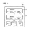
- FIG. 3 is a diagram showing an example of an operation screen 150 displayed on the operation panel 120. As shown in FIG. This operation screen 150 is displayed on a touch panel of the operation panel 120 in response to an instruction transmitted from the CPU 101. Fig. 3 shows a screen for setting the target temperatures for cooling and heating, which is displayed in response to the operation of the setting button 181.
- This operation screen 150 is provided with a cooling temperature setting section 160 and a heating temperature setting section 170.
- the operator can input a desired temperature into input fields 161, 171 using keys or the like displayed in a pop-up display, and operate change buttons 162, 172 to set the target temperatures for cooling and heating.
- This target temperature is referred to by the control device 100 , but it does not have to be the same as the set temperature set by the remote controller 240 and referred to by the control unit 220 of the air conditioner 400 .
- the bypass mode button 182 is a button for toggling on and off the bypass mode in which the relay switch 109 is always connected to terminal a. During bypass mode, the control device 100 has no effect on the operation of the air conditioner 400.
- the data save button 183 is a button for toggling the saving of the operation log of the control device 100 on and off.
- saving is on, for example, the operating time, the time when the relay switch 109 was connected to the terminal b side, the timing when each judgment in FIG. 4 and FIG. 5 became Yes, etc. are saved in the memory 102 as an operation log.
- This operation log can be read out to an external PC or the like via the communication I/F 103.
- the current sensor 114 can be used to detect the total amount of current supplied from the power supply circuit 230 to each part of the air conditioner 400, or the amount of current supplied to the compressor 311, and these current amounts can also be saved as an operation log. Based on this information, the change in energy consumption depending on whether the bypass mode is on or off can be analyzed, and the amount of energy consumption reduction by the control device 100 can be estimated.
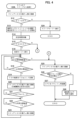
- the process shown here is a process according to an embodiment of a temperature adjustment device control method of the present invention.
- the process of each step will be explained as being executed by the control device 100.
- the control device 100 first connects the relay switch 109 to the terminal a side (S11).
- the relay switch 109 is configured to be connected to the terminal a side when no control signal is supplied, so it should be connected to the terminal a side at startup, and the process of step S11 can be omitted.
- the control device 100 determines whether the state of the detection signal E1, which indicates the operating state of the power supply circuit 230, is ON (operating) (S12). If it is not operating, the control device 100 does not need to control the air conditioner 400, so it transitions to sleep mode (S24) and ends the process. It is advisable to monitor the detection signal E1 even during sleep mode, and execute the process of FIG. 4 again if it is ON. In the process of step S12, the CPU 101 functions as an operation detection unit.
- the control device 100 activates each of the temperature sensors 111-113 and starts monitoring the detection signals T1-T3 (S13). It then waits for a predetermined time (S14).
- the predetermined time is set to the time required for the compressor 311 to operate for a sufficient period of time after the air conditioner 400 has not been used for a while and is then turned on, to allow cool air (in cooling mode) or warm air (in heating mode) to be discharged from the exhaust port 215 of the indoor unit 200. This time can be set to, for example, two minutes.
- the predetermined time may be set to a longer time.
- the control device 100 judges whether the detection signal T2 of the exhaust temperature sensor 112 indicates 25° C. or less (S15). If this is Yes, it is determined that the indoor unit 200 is discharging cool air and therefore the air conditioner 400 is performing a cooling operation, and the control device 100 transitions to cooling mode control (first control) (S16) and proceeds to the processing of step S17 and thereafter. If the answer is No in step S15, it is determined that the indoor unit 200 is discharging warm air and therefore the air conditioning device 400 is performing heating operation, and the control device 100 transitions to heating mode control (second control) (S31 in FIG. 5) and proceeds to processing from step S32 onwards.
- first control cooling mode control
- second control heating mode control
- the 25°C used as the standard in step S15 is selected as a temperature higher than the cold air temperature discharged during cooling operation and lower than the warm air temperature discharged during heating operation in most air conditioners 400, regardless of the model, but the specific numerical value is not limited to this.
- air conditioners 400 regardless of the set room temperature for cooling or heating and the actual room temperature, the temperature of the cold air and warm air discharged when the room temperature is relatively stable is usually within a limited range. For this reason, assuming the state after the specified time in step S14 has elapsed, it is usually possible to determine a standard temperature such as the above 25°C. Furthermore, the temperature of the intake air C does not need to be taken into account in the judgment in step S15.
- the control device 100 determines whether or not the temperature indicated by the detection signal T1 from the intake air temperature sensor 111 (i.e., the air temperature in the room in which the indoor unit 200 is installed) has become lower than the cooling target temperature (first target temperature) set on the screen of Figure 3 within a predetermined upper limit time (S17, S18).
- the predetermined upper limit time used in step S17 is set to a time during which the indoor air temperature is considered to sufficiently reach the cooling target temperature, taking into consideration the predetermined time in step S14, even when the air conditioner 400 is turned on after not being used for a while. For example, it may be set to 3 minutes.
- step S17 becomes Yes, and error processing from step S25 onwards is entered. That is, the control device 100 connects the relay switch 109 to the terminal a side (S25), and if the number of consecutive resets is less than a predetermined number, resets and restarts the CPU 101 (S26, S27). A retry is performed in consideration of cases such as when the detection signal from the sensor is not being input normally. If the number of consecutive resets exceeds a predetermined number, the notification unit 104 notifies the operator of the occurrence of an abnormality by light, sound, etc., and ends the processing (S28). In this case, the air conditioning function of the air conditioner 400 is not working normally, or a sensor on the control device 100 side may have failed, so the control device 100 is stopped.
- step S18 the control device 100 stores the temperature T3m indicated by the detection signal T3 from the heat exchanger temperature sensor 113 at that time (S19), and connects the relay switch 109 to terminal b (S20). This causes the above-mentioned first control signal (compressor stop signal) to be output from the Tinx terminal of the input/output I/F 105 to the control unit 220.
- the control unit 220 is expected to stop the compressor 311 when the first control signal is input.
- control device 100 continues to output the compressor stop signal until the temperature indicated by the detection signal T3 from the heat exchanger temperature sensor 113 becomes equal to or higher than T3m+0.5°C (the temperature of T3 rises by equal to or higher than the first threshold value), and thereafter the temperature indicated by the detection signal T2 from the exhaust temperature sensor 112 becomes equal to or higher than the cooling target temperature+0.5°C (the second target temperature) (S21, S22). During this time, the compressor 311 remains stopped.
- step S22 the control device 100 connects the relay switch 109 to the terminal a (S23). This causes the detection signal Tin of the temperature sensor 213 provided in the air conditioner 400 to be input directly to the control unit 220, and the control unit 220 then controls the operation and stop of the compressor 311 according to the original control function of the air conditioner 400. And, since at this point the indoor unit 200 is in a state where it is unable to discharge cold air below the cooling target temperature, it is expected that the control unit 220 will operate the compressor 311 immediately or in the near future, and the discharge of cold air from the indoor unit 200 will resume. Thereafter, the process returns to step S17 and is repeated.
- steps S18 and S20 are intended to forcibly stop the compressor 311 when the indoor air temperature drops to the cooling target temperature, as further cooling is no longer necessary, thereby reducing energy consumption.
- the control algorithm original to the air conditioner 400
- the control device 100 can intervene in this control and stop the compressor 311, thereby reducing energy consumption.
- step S21 essentially determines whether the room temperature is being maintained compared to the time when the compressor 311 was stopped, that is, the time when the room temperature became the cooling target temperature, and if the efficiency of heat absorption has decreased to a certain extent, it will be Yes.
- the "+0.5°C" part can be determined depending on how much of a decrease in heat absorption efficiency is acceptable.
- step S22 the stop of the compressor 311 is released at the point in time when the temperature of the exhaust air D actually exceeds the cooling target temperature (+ ⁇ ) and it becomes impossible to maintain the room temperature at the cooling target temperature without operating the compressor 311. This makes it possible to minimize the time during which the compressor 311 is operated, thereby reducing the energy consumption of the air conditioner 400 .
- the value of + ⁇ is +0.5°C, but it is not limited to this value. If ⁇ is large, it is expected that it will take a long time for the temperature of exhaust D to drop after relay switch 109 is switched over, resulting in large fluctuations in room temperature. On the other hand, if ⁇ is small, the time that compressor 311 is stopped will be short, resulting in less energy saving effect. An appropriate value can be set taking these factors into consideration. There is no prohibition on setting it to a negative value.
- step S21 will be Yes before the judgment in step S22.
- the judgment in step S21 is also made, and the compressor 311 is released from the stopped state after this judgment has become Yes, thereby making it possible to determine the release timing more accurately and achieving greater energy savings.
- the actual room temperature may temporarily become lower than the target cooling temperature due to the remaining cooling capacity. This is a temperature drop that does not meet the user's needs, and consuming energy for this purpose may be considered a waste.
- step S18 by comparing T1 with a value higher than the actual cooling target temperature in step S18, it is believed that it is possible to further reduce energy consumption while keeping the room temperature at the temperature desired by the user. How many degrees higher than the cooling target temperature should be will vary depending on the installation environment of the indoor unit 200 and the outdoor temperature, but it is preferable to set the temperature difference so that the room temperature (T1) just reaches the cooling target temperature at or shortly before step S22 becomes Yes. In many environments, it is expected that this can be achieved with a temperature difference of around 0.5°C to 2°C.
- the control device 100 first determines whether or not the ceiling mounting mode is set (S32).
- the ceiling mounting mode takes into consideration that warm air tends to accumulate at the top when the indoor unit 200 is mounted on the ceiling of a room, and in order to properly determine whether the room temperature has reached the heating target temperature, the intake air temperature is compared with a temperature higher than the heating target temperature in step S36. In other words, when the ceiling mounting mode is set, the third target temperature is set higher than when it is not. Since the installation position of the indoor unit 200 is usually fixed, the ceiling mounting mode can be set by the installer when installing the control device 100, and there is no need to change it thereafter.
- the temperature indicated by the detection signal T1 from the intake air temperature sensor 111 i.e., the air temperature inside the room where the indoor unit 200 is installed
- the heating target temperature third target temperature set on the screen of FIG. 3 within a specified upper limit time (S33, S34).
- the ceiling-mounted mode it is determined whether or not the temperature indicated by the same T1 has reached or exceeded the heating target temperature + 3°C (third target temperature) (S35, S36).
- This value of +3°C is just an example, and an appropriate value can be set based on factors such as the temperature difference between the temperature near the ceiling when the unit is mounted on the ceiling and an appropriate location in the room.
- the predetermined upper limit time used in steps S33 and S35 is set to a time that is considered long enough for the indoor air temperature to reach the heating target temperature, taking into consideration the predetermined time in step S14, even when the air conditioner 400 is turned on after not being used for a while. For example, it may be set to three minutes, but it is not essential to set the same time as in the cooling mode. In either case, if step S34 or S36 does not become Yes within the upper limit time, step S33 or S35 becomes Yes, and the process enters error processing from step S25 onward in FIG. 4, as in the cooling mode.
- step S34 or S36 the control device 100 stores the temperature T3m indicated by the detection signal T3 from the heat exchanger temperature sensor 113 at that time (S37), and connects the relay switch 109 to terminal b (S38). This is the same operation as steps S19 and S20 in the cooling mode, and it is expected that this will cause the control unit 220 to stop the compressor 311.
- the control device 100 continues to output the first control signal (compressor stop signal) until the temperature indicated by the detection signal T3 from the heat exchanger temperature sensor 113 falls below T3m stored in step S37 (the temperature of T3 falls by more than the second threshold value ⁇ 0) and thereafter the temperature indicated by the detection signal T2 from the exhaust temperature sensor 112 falls below the heating target temperature (fourth target temperature) (S39, S40). During this time, the compressor 311 remains stopped.
- step S40 the control device 100 connects the relay switch 109 to the terminal a (S41).
- the control unit 220 controls the operation and stop of the compressor 311 according to the original control function of the air conditioner 400, as in step 23 in the cooling mode.
- the indoor unit 200 is in a state where it is unable to discharge warm air above the heating target temperature, it is expected that the control unit 220 will operate the compressor 311 immediately or in the near future, and the discharge of warm air from the indoor unit 200 will resume. Thereafter, the process returns to step S32 and is repeated.
- steps S34, S36, and S38 are intended to forcibly stop the compressor 311 and reduce energy consumption when the indoor air temperature reaches the heating target temperature and further heating is no longer necessary.
- the control algorithm original to the air conditioner 400
- the control device 100 can intervene in this control and stop the compressor 311, reducing energy consumption.
- step S39 essentially determines whether the room temperature is being maintained compared to the time when the compressor 311 was stopped, i.e., the time when the room temperature became the heating target temperature, and if the heating efficiency has decreased to a certain extent, the answer is Yes. Depending on how much of a decrease in heat absorption efficiency is acceptable, a value slightly smaller than T3m may be used as the comparison target.
- step S40 the stop of the compressor 311 is released at the point in time when the temperature of the exhaust air D actually falls below the heating target temperature and it becomes impossible to maintain the room temperature at the heating target temperature without operating the compressor 311. This makes it possible to minimize the time during which the compressor 311 is operated, thereby reducing the energy consumption of the air conditioner 400 .
- the value to be compared with T2 in step S40 is the heating target temperature itself, but it is not limited to this value.
- the heating target temperature - ⁇ is used as the comparison, it is expected that if ⁇ is large, it will take a long time for the temperature of the exhaust D to rise after the relay switch 109 is switched over, resulting in large fluctuations in room temperature, whereas if ⁇ is small, the time that the compressor 311 is stopped will be short, resulting in less energy saving effect.
- An appropriate value can be set taking these factors into consideration. There is no prohibition on ⁇ being a negative value.
- step S39 will be Yes before the judgment in step S40.
- the reason why the judgment in step S39 is provided despite this, and the reason why it may be omitted, are the same as the judgment in step S21 described in the cooling mode.
- the indoor heat exchanger 211 still has heat dissipation capacity for a while, if the compressor 311 is stopped when the heating target temperature is reached, a temperature rise that does not meet the user's needs will occur, just as in the case of cooling. Then, in the heating mode, by comparing T1 with a value lower than the actual heating target temperature in step S34, it is possible to further reduce energy consumption while keeping the room temperature at the temperature desired by the user. The appropriate temperature difference is the same as in the cooling mode.
- the comparison target in step S36 in the ceiling mounted mode may be a temperature higher than the value in step S34 in the normal mode.
- the control device 100 described above performs the processing shown in Figures 4 and 5, temporarily interrupting the control of the compressor 311 by the control unit 220 in the air conditioner 400, essentially forcibly stopping the compressor 311, and by reducing the operating time of the compressor 311 compared to when the control device 100 is not present, the energy consumption of the air conditioner 400 is reduced.
- control device 100 when installing the control device 100, it is only necessary to place temperature sensors in three places on the indoor unit 200 and connect the input/output I/F 105 so that it interrupts the signal line from the temperature sensor 213 to the control unit 220, and there is no need to modify other parts of the air conditioner 400. For this reason, the control device 100 is easy to install, and the possibility of the installation of the control device 100 causing a malfunction in the air conditioner 400 is extremely low.
- the control device 100 executes steps S51 to S53 in Fig. 6 instead of step S23 when the determination in step S22 in Fig. 4 is Yes. That is, when it is time to operate the compressor 311, instead of causing the control unit 220 to control the compressor 311 according to its original control function, a compressor operation signal is sent to the control unit 220 to control the compressor 311 to operate at a rated speed (S51). At this point, the relay switch 109 is kept connected to the terminal b, and the compressor operation signal is sent from the Tinx terminal of the input/output I/F 105.
- step S51 the process proceeds to step S17 in Fig. 4, and the rated operation of compressor 311 will be continued until the room temperature becomes equal to or lower than the cooling target temperature in step S18.
- step S52 when the room temperature indicated by detection signal T1 from intake air temperature sensor 111 reaches a temperature slightly higher (by positive value X) than the cooling target temperature, relay switch 109 is connected to terminal a (S53), and control unit 220 is returned to a state in which it controls compressor 311 according to its original control function, and then the process proceeds to step S17 in FIG. 4.
- step S18 the compressor operation signal may be sent similarly if the answer is Yes in step S40.
- the determination corresponding to step S52 may be "Is T1 ⁇ the heating target temperature ⁇ X?"
- the second embodiment is an example in which a control device 100 for controlling a compressor 311 is installed in an air conditioner 400 of a type in which a single outdoor unit is shared by a plurality of indoor units.
- a control device 100 for controlling a compressor 311 is installed in an air conditioner 400 of a type in which a single outdoor unit is shared by a plurality of indoor units.
- parts that are common to or correspond to the first embodiment will be designated by the same reference numerals as in the first embodiment, and descriptions of the common parts will be omitted as appropriate.
- FIG. 7 shows a schematic configuration of the control device 100 of the second embodiment and an air conditioner 400, which is an example of a temperature adjustment device that is the target of control by the control device 100.
- FIG. 7 shows only the configuration of the refrigerant circuit 410, the refrigerant pipe 310, the compressor 311, the outdoor heat exchanger 313, and the indoor heat exchangers 211a-211c, and omits illustration of the outdoor fan 321, the indoor fan 212, power supplies, and the wall 500.
- the refrigerant pipe 310 shows a connection during cooling operation, but it is possible to switch between heating and cooling as in the case of FIG. 1.
- the air conditioner 400 in the second embodiment is equipped with three indoor units 200a-200c and one outdoor unit 300, and is configured with a refrigerant circuit 410 that passes sequentially through the outdoor heat exchanger 313 of the outdoor unit 300 and the indoor heat exchangers 211a-211c of each of the indoor units 200a-200c.
- the refrigerant discharged from the compressor 311 and dissipating heat in the outdoor heat exchanger 313 is decompressed and flows to each of the indoor heat exchangers 211a-211c, cooling the intake air C of each of the indoor units 200a-200c.
- Each of the indoor units 200a to 200c is equipped with a control unit 220a to 220c, but of these, only the control unit 220a of the indoor unit 200a is involved in controlling the outdoor unit 300.
- the indoor unit 200a that controls the outdoor unit 300 is often called the parent unit, and the other indoor units 200b and 200c are called child units.
- the control unit 220a of the indoor unit 200a which is the parent unit, transmits control signals C1a to Cna to each part of the air conditioner 400 based on detection signals from sensors provided in each part of the air conditioner 400, including the outdoor unit 300 side on the indoor unit 200a side, to control the operation of each part, like the control unit 220 of the indoor unit 200 in the first embodiment.
- the signals with the second suffix from 1 to (i-1) are signals for controlling the outdoor unit 300 side
- the signals with the suffix from i to n are signals for controlling the indoor unit 200a side.
- the third suffix a indicates that it is an output signal from the control unit 220a.
- Signal lines (not shown) for transmitting these control signals C1a to C(i-1)a are wired between the indoor unit 200a and the outdoor unit 300. Further, a remote controller 240 for operating the air conditioner 400 is connected to the control section 220a of the parent unit.
- the child unit's control units 220b, 220c send control signals Cib-Cnb and Cic-Cnc to each part of the indoor units 200b, 200c based on detection signals from sensors provided in each part of the indoor units 200b, 200c, respectively, to control the operation of each part.
- the subscripts have the same meaning as in the case of the control unit 220a.
- the indoor unit 200a is equipped with a temperature sensor 213a corresponding to the temperature sensor 213 of the first embodiment, and when only the air conditioner 400 is installed, wiring is performed so that the detection signal Tina of the temperature sensor 213a is input to the Tin terminal of the control unit 220a.
- the control device 100 when the control device 100 is installed, wiring is performed so that the detection signal Tina of the temperature sensor 213a is input to the control device 100, and the control signal Tinx output by the control device 100 is input to the Tin terminal of the control unit 220a.
- the meaning of this wiring is the same as in the first embodiment. That is, the control device 100 of the second embodiment is installed so as to supply a control signal to the control unit 220a of the parent unit. This corresponds to the control unit 220a of the parent unit controlling the operation and stop of the compressor 311.
- the child unit also has temperature sensors 213b and 213c corresponding to temperature sensor 213, and their detection signals Tinb and Tinc are input to the Tin terminals of control units 220b and 220c, respectively.
- control units 220b and 220c are not involved in the control of compressor 311, these detection signals Tinb and Tinc do not affect the operation of compressor 311.
- intake air temperature sensor 111a As temperature sensors to be connected to the control device 100, first, intake air temperature sensor 111a, exhaust air temperature sensor 112a, and heat exchanger temperature sensor 113a similar to the temperature sensors 111-113 of the first embodiment are installed in the indoor unit 200a, which is the parent unit, and detection signals T1a-T3a are input.
- intake air temperature sensors 111b, 111c, exhaust air temperature sensors 112b, 112c, and heat exchanger temperature sensors 113b, 113c are installed in the corresponding positions in the indoor units 200b, 200c, which are child units, respectively, and detection signals T1b-T3b, T1c-T3c are input to the control device 100.
- a human presence sensor 130 that detects whether a person is present near any indoor unit by infrared rays, ultrasonic waves, or the like is also connected to the control device 100, and a detection signal H1 is input thereto.
- the human presence sensor 130 is not essential.
- FIG. 8 shows a hardware configuration of the control device 100 according to the second embodiment.
- the input/output I/F 105 has a function of inputting detection signals T1a to T3c, E1 (see FIG. 1), H1, and Tina from the various sensors shown in FIG. 7, and outputting a control signal Tinx to the control unit 220a.
- the input/output I/F 105 includes a selector for selecting which of T1a to T3a, T1b to T3b, or T1a to T3c to use as the temperature sensor detection signal when the control device 100 executes the processes shown in FIGS. 4 and 5, in other words, for selecting which of the indoor units the detected temperature of the temperature sensor to use.
- the other hardware configuration is similar to that described in the first embodiment with reference to FIG.
- FIG. 9 is a diagram showing an example of an operation screen 150 displayed on the operation panel 120. As shown in FIG. This operation screen 150 differs from the example shown in FIG. 3 only in that a temperature reference setting section 190 is added.
- the temperature reference setting section 190 is provided with a window-side button 191, a center button 192, a wall-side button 193, and an automatic button 194, and only one of these can be turned on.
- the window-side button 191, the center button 192, and the wall-side button 193 are buttons for manually selecting which of the three indoor units 200a to 200c the control device 100 will use to control the operation of the compressor based on the temperature of the temperature sensor installed therein. For example, if indoor unit 200a is installed by a window in the room, indoor unit 200b is installed in the center of the room, and indoor unit 200c is installed by a wall in the room, it is thought that during the day, the room temperature on the wall side is more likely to drop due to air conditioning, and the temperature sensor installed in indoor unit 200c will tend to output a lower temperature than the temperature sensor installed in indoor unit 200a.
- the automatic button 194 is a button for setting the control to be performed based on the temperature detected by the temperature sensor of the indoor unit in the location with the most people, based on the detection signal from the human presence sensor 130. By using this control, it is possible to perform air conditioning that is comfortable for many people in the room, while saving energy as much as possible within that range.
- control device 100 of the second embodiment executes the processing of Figures 4 and 5 based on the detected temperature of a temperature sensor installed in a selected one of the three indoor units 200a to 200c, so that even in an air conditioning device 400 of a type in which a single outdoor unit 300 is shared by multiple indoor units 200a to 200c, it is possible to maintain the room temperature at a set temperature while reducing the operating time of the compressor 311, thereby achieving energy savings. It is also possible to execute the processes in Figures 4 and 5 using the average values of temperatures detected by the temperature sensors of all indoor units or a number of arbitrarily selected indoor units, rather than a single specific indoor unit. In this way, control can be performed based on the average indoor conditions.
- FIG. 10 This concludes the explanation of the embodiment, but in this invention, the specific configuration of the device or system, specific processing procedures, parameter values, sensor placement, use and configuration of the temperature adjustment device, etc. are not limited to those described in the embodiment.
- the control device 100 does not need to be able to control both the cooling mode and the heating mode, and may be configured to perform only one of the two modes corresponding to the air conditioner 400 to be controlled. In other words, the judgment in step S15 in FIG. 4 is not necessary.
- control device 100 automatically switches between the heating mode and the cooling mode, but the mode may be set manually. In this case, the determination in step S15 in FIG. 4 is also unnecessary. Also, it is not essential to provide the ceiling installation mode. In the heating mode, the temperature to be compared with T1 may be only one, as in steps S34 and S36 in Fig. 5. In this case, it is conceivable to adopt a temperature intermediate between steps S34 and S36, but this is not limiting.
- step S21 in FIG. 4 or step S39 in FIG. 5 there is no need to install the heat exchanger temperature sensor 113.
- the values of the temperature and other criteria shown in FIG. 4 and FIG. 5 are merely examples, and the values are not limited to those used in the explanation.
- the setting of the target temperature for heating and cooling in the control device 100 by the operation panel 120 is performed independently of the setting of the heating and cooling set temperature on the air conditioner 400 side by the remote colon and roller 240.
- the control device 100 it is also possible for the control device 100 to detect the set temperature signal from the remote colon and roller 240 and automatically make the target temperature on the control device 100 side track the set temperature indicated by the set temperature signal (the set temperature on the air conditioner 400 side). This prevents the set temperatures on the air conditioner 400 side and the control device 100 side from being set to temperatures that are far apart, and prevents a situation in which the control of the control device 100 does not function properly due to differences in set temperatures.
- buttons 163, 173 can be added to the cooling temperature setting section 160 and the heating temperature setting section 170 on the operation screen 150, respectively, so that these buttons can be used to toggle on and off automatic tracking of the target temperature for cooling and heating, respectively.
- control device 100 is configured as a device that is retrofitted to the air conditioner 400, but a control unit that performs control similar to that of the control device 100 may be built into the air conditioner 400 from the beginning.
- the sending of the compressor stop signal in Figures 4 and 5 can be thought of as a forced stop of the compressor 311, and the connection to the terminal a side of the relay switch 109 as switching between operation and stop of the compressor 311 based on the temperature detected by the temperature sensor 213.
- the temperature sensor referenced by the control device 100 in the processing of Figures 4 and 5 is provided separately from the temperature sensor that the indoor unit 200 comes standard with.
- the temperature sensor 213 and the intake air temperature sensor 111 are located in the same position and have the same measurement target. Therefore, if the control device 100 is capable of controlling the temperature sensor 213 and can properly grasp the correspondence between the detection signal and the detected temperature, it is also conceivable that the control device 100 can perform the processing of Figures 4 and 5 by referring to the detection signal of the temperature sensor 213 that comes standard with the indoor unit 200. If the indoor unit 200 has another usable sensor, it may be substituted in a similar manner.
- control device 100 in addition, in the above embodiment, an example was described in which the object to be controlled by the control device 100 was an air conditioner, but the present invention is not limited to this.
- a similar control device 100 can also be used to control the operation of compressors in temperature adjustment devices that use a compressor and a heat exchanger to cool or heat gas, such as refrigerators, freezers, heat retention devices, and heating devices.
- the temperature adjustment device may be a device that performs only one of cooling and heating. In this case, the gas to be temperature-adjusted does not need to be in a closed space such as a room. Naturally, open refrigerators and the like can also be controlled.
- a program embodiment of the present invention is a program for causing a computer to control required hardware to realize the functions of the control device 100 in the above-described embodiment.
- a program may be stored in a ROM or other non-volatile storage medium (flash memory, EEPROM, etc.) that is included in the computer from the beginning.
- flash memory flash memory
- EEPROM electrically erasable programmable read-only memory
- it may also be provided by recording it on any non-volatile recording medium such as a memory card, CD, DVD, or Blu-ray disc.
Landscapes
- Engineering & Computer Science (AREA)
- Chemical & Material Sciences (AREA)
- Combustion & Propulsion (AREA)
- Mechanical Engineering (AREA)
- General Engineering & Computer Science (AREA)
- Signal Processing (AREA)
- Physics & Mathematics (AREA)
- Fuzzy Systems (AREA)
- Mathematical Physics (AREA)
- Thermal Sciences (AREA)
- Air Conditioning Control Device (AREA)
Abstract
Description
この発明は、温度調整装置を制御するための制御装置、このような制御装置と温度調整装置とを備える温度調整システム、温度調整装置の制御方法、およびプロセッサに温度調整装置を制御するための手順を実行させるためのプログラムに関する。 The present invention relates to a control device for controlling a temperature adjustment device, a temperature adjustment system including such a control device and a temperature adjustment device, a control method for a temperature adjustment device, and a program for causing a processor to execute a procedure for controlling the temperature adjustment device.
従来から、所定領域の温度を調整する温度調整装置として、冷暖房機能を有する空気調整装置や、冷蔵庫、冷凍庫などの冷却装置が広く用いられている。このような温度調整装置では、配管内に密閉した冷媒を、圧縮機(コンプレッサ)及び減圧機を用いて、圧縮及び膨張させつつ、吸熱側と排熱側にそれぞれ配置した2つの熱交換器を通じて、吸熱側の熱を冷媒に乗せ、排熱側で冷媒の熱を捨てることで、吸熱側の熱を排熱側に移動させる。吸熱側が室内や庫内であれば、温度調整装置は冷房、冷蔵、冷凍装置として機能し、排熱側が室内や庫内であれば、温度調整装置は暖房、保温、加熱装置として機能する。 Conventionally, air conditioning devices with cooling and heating functions, and cooling devices such as refrigerators and freezers have been widely used as temperature adjustment devices that adjust the temperature of a specific area. In such temperature adjustment devices, a refrigerant sealed inside a pipe is compressed and expanded using a compressor and a pressure reducer, and the heat on the heat absorption side is transferred to the heat exhaust side by transferring the heat of the refrigerant to the heat exhaust side through two heat exchangers arranged on the heat absorption side and the heat of the refrigerant is discarded on the heat exhaust side. If the heat absorption side is inside a room or a cabinet, the temperature adjustment device functions as an air conditioner, refrigeration, or freezer, and if the heat exhaust side is inside a room or a cabinet, the temperature adjustment device functions as a heater, heat retention, or heating device.
このような温度調整装置では、主なエネルギ消費は圧縮機を駆動する際に生じ、その消費量も大きいものとなる。
そして、冷却剤系システム、冷蔵及び加熱システムにおける圧縮機のオンオフの制御を工夫することで、エネルギ消費を低減するため技術が特許文献1に提案されている。
In such a temperature adjustment device, the main energy consumption occurs when driving the compressor, and the amount of energy consumed is also large.
Patent Document 1 proposes a technique for reducing energy consumption by devising on/off control of compressors in refrigerant systems, refrigeration and heating systems.
しかしながら、特許文献1に記載の技術では、エネルギ消費の低減率が必ずしも十分ではなかった。
本発明は、このような背景でなされたものであり、温度調整装置における圧縮機の動作を適切に制御して、温度調整機能に与える影響を抑えつつ消費エネルギを低減することを目的とする。また、既設の温度調整装置に対してもこのような制御機能を容易に追加できるようにすることも、目的とする。
However, the technology described in Patent Document 1 does not necessarily achieve a sufficient reduction rate in energy consumption.
The present invention has been made against this background, and aims to appropriately control the operation of a compressor in a temperature control device to reduce energy consumption while minimizing the impact on the temperature control function, and also to make it possible to easily add such a control function to an existing temperature control device.
上記の目的を達成するため、この発明の制御装置は、圧縮機、熱交換器、吸気部、排気部、温度センサ及び制御部を備え、上記吸気部から吸入した気体に対して上記熱交換器で熱交換を行って上記排気部から排出し、上記温度センサから供給される信号に基づき上記制御部が上記圧縮機の動作を制御する温度調整装置を制御する制御装置において、上記吸気部に配置され吸入される上記気体の温度を検出する吸気温度センサと、上記排気部に配置され排出される上記気体の温度を検出する排気温度センサと、上記温度調整装置の稼働有無を検出する稼働検出部と、上記温度調整装置の稼働開始から所定時間以上経過した後で、上記吸気温度センサの検出温度が所定の第1目標温度以下になった場合に、上記制御部に上記圧縮機を停止又は低速運転させる制御を行わせるための第1制御信号を上記制御部へ出力し、その後、上記排気温度センサの検出温度が上記第1目標温度に基づき定められた第2目標温度以上になった場合に、上記第1制御信号の上記制御部への出力を停止する第1制御を行うことが可能な制御信号出力部とを設けたものである。 In order to achieve the above object, the control device of the present invention includes a compressor, a heat exchanger, an intake section, an exhaust section, a temperature sensor, and a control section, and controls a temperature adjustment device in which gas sucked in through the intake section is subjected to heat exchange in the heat exchanger and exhausted through the exhaust section, and the control section controls the operation of the compressor based on a signal supplied from the temperature sensor. The control device includes an intake temperature sensor disposed in the intake section and detecting the temperature of the gas sucked in, an exhaust temperature sensor disposed in the exhaust section and detecting the temperature of the gas exhausted, an operation detection section that detects whether the temperature adjustment device is operating, and a control signal output section that is capable of performing a first control to output a first control signal to the control section to cause the control section to control the compressor to stop or operate at a low speed when the temperature detected by the intake temperature sensor becomes equal to or lower than a predetermined first target temperature after a predetermined time has elapsed since the start of operation of the temperature adjustment device, and to stop outputting the first control signal to the control section when the temperature detected by the exhaust temperature sensor becomes equal to or higher than a second target temperature determined based on the first target temperature.
このような制御装置において、上記熱交換器に配置され上記熱交換器の温度を検出する熱交換器温度センサを設け、上記制御信号出力部が、上記第1制御において、上記温度調整装置の稼働開始から上記所定時間以上経過した後で、上記吸気温度センサの検出温度が上記第1目標温度以下になった場合に、上記熱交換器温度センサの検出温度を記憶し、その後、上記熱交換器温度センサの検出温度が、上記記憶した検出温度と比較して所定の第1閾値以上上昇した後で、上記排気温度センサの検出温度が上記第2目標温度以上になった場合に、上記第1制御信号の上記制御部への出力を停止するとよい。 In such a control device, a heat exchanger temperature sensor is provided that is disposed in the heat exchanger and detects the temperature of the heat exchanger, and the control signal output unit stores the detected temperature of the heat exchanger temperature sensor when the detected temperature of the intake air temperature sensor becomes equal to or lower than the first target temperature after the predetermined time has elapsed since the temperature adjustment device started operating in the first control, and thereafter, when the detected temperature of the heat exchanger temperature sensor rises by a predetermined first threshold value or more compared to the stored detected temperature and the detected temperature of the exhaust air temperature sensor becomes equal to or higher than the second target temperature, the control signal output unit stops outputting the first control signal to the control unit.
あるいは、上記制御信号出力部は、上記温度調整装置の稼働開始から上記所定時間経過した時点の上記排気温度センサの検出温度が所定の第2閾値以上か否かに応じて、冷房モードと暖房モードとを切り換え、上記冷房モードにおいては上記第1制御を行い、上記暖房モードにおいては、上記温度調整装置の稼働開始から上記所定時間以上経過した後で、上記吸気温度センサの検出温度が所定の第3目標温度以上になった場合に、上記第1制御信号を上記制御部へ出力し、その後、上記排気温度センサの検出温度が上記第3目標温度に基づき定められた第4目標温度以下になった場合に、上記第1制御信号の上記制御部への出力を停止する第2制御を行うとよい。 Alternatively, the control signal output unit switches between cooling mode and heating mode depending on whether the detected temperature of the exhaust temperature sensor at the time when the predetermined time has elapsed since the start of operation of the temperature adjustment device is equal to or higher than a predetermined second threshold, and performs the first control in the cooling mode, and in the heating mode, outputs the first control signal to the control unit when the detected temperature of the intake air temperature sensor is equal to or higher than a predetermined third target temperature after the predetermined time has elapsed since the start of operation of the temperature adjustment device, and then performs a second control to stop outputting the first control signal to the control unit when the detected temperature of the exhaust temperature sensor is equal to or lower than a fourth target temperature determined based on the third target temperature.
あるいは、上記制御信号出力部が、上記温度調整装置の稼働開始から上記所定時間経過した時点の上記排気温度センサの検出温度が所定の第2閾値以上か否かに応じて、冷房モードと暖房モードとを切り換え、上記冷房モードにおいては上記第1制御を行い、上記暖房モードにおいては、上記温度調整装置の稼働開始から上記所定時間以上経過した後で、上記吸気温度センサの検出温度が所定の第3目標温度以上になった場合に、上記第1制御信号を上記制御部へ出力すると共に上記熱交換器温度センサの検出温度を記憶し、その後、上記熱交換器温度センサの検出温度が、上記記憶した検出温度と比較して所定の第2閾値以上下降した後で、上記排気温度センサの検出温度が上記第3目標温度に基づき定められた第4目標温度以下になった場合に、上記第1制御信号の上記制御部への出力を停止する第2制御を行うとよい。 Alternatively, the control signal output unit switches between cooling mode and heating mode depending on whether the detected temperature of the exhaust temperature sensor at the time when the predetermined time has elapsed since the start of operation of the temperature adjustment device is equal to or higher than a predetermined second threshold, and performs the first control in the cooling mode, and in the heating mode, if the detected temperature of the intake air temperature sensor becomes equal to or higher than a predetermined third target temperature after the predetermined time has elapsed since the start of operation of the temperature adjustment device, outputs the first control signal to the control unit and stores the detected temperature of the heat exchanger temperature sensor, and then performs a second control to stop outputting the first control signal to the control unit when the detected temperature of the heat exchanger temperature sensor drops by equal to or higher than the predetermined second threshold compared to the stored detected temperature and the detected temperature of the exhaust temperature sensor becomes equal to or lower than a fourth target temperature determined based on the third target temperature.
また、上記のいずれかの制御装置において、上記暖房モードの動作を、通常の暖房モードと、上記通常の暖房モードと比べて第3目標温度が高く、上記第4目標温度が同じである天井据付暖房モードとの間で切り換え可能であるとよい。
さらに、上記のいずれかの制御装置において、上記温度調整装置は、交流電源によって駆動され端子を介して当該温度調整装置のリモートコントローラに直流電源を供給するための電源回路を備え、当該制御装置は直流電源によって駆動され、上記温度調整装置の上記端子に電気的に接続するための接続部を備えるとよい。
In addition, in any of the above control devices, it is preferable that the operation of the heating mode be switchable between a normal heating mode and a ceiling-mounted heating mode in which the third target temperature is higher than in the normal heating mode and the fourth target temperature is the same.
Furthermore, in any of the above control devices, the temperature adjustment device may be driven by an AC power source and include a power supply circuit for supplying DC power to a remote controller of the temperature adjustment device via a terminal, and the control device may be driven by a DC power source and include a connection portion for electrically connecting to the terminal of the temperature adjustment device.
また、この発明の温度調整システムは、上記のいずれかの制御装置と、上記温度調整装置とを備え、上記温度調整装置が、交流電源によって駆動され端子を介して当該温度調整装置のリモートコントローラに直流電源を供給するための電源回路を備え、当該制御装置は直流電源によって駆動され、上記温度調整装置の上記端子から電源が供給されるものである。 The temperature adjustment system of the present invention includes any one of the control devices described above and the temperature adjustment device described above, and the temperature adjustment device includes a power supply circuit that is driven by an AC power source and supplies DC power to a remote controller of the temperature adjustment device via a terminal, and the control device is driven by a DC power source and receives power from the terminal of the temperature adjustment device.
また、上記のいずれかの制御装置において、上記制御信号出力部が、上記第1制御信号の上記制御部への出力を停止する際に、上記制御部に上記圧縮機を定格運転する制御を行わせるための第2制御信号を上記制御部へ出力するとよい。
さらに、上記制御信号出力部が、上記第2制御信号を上記制御部へ出力した後、次に上記第1制御信号を上記制御部へ出力するよりも前に、上記第2制御信号の上記制御部への出力を停止するとよい。
In addition, in any of the above control devices, when the control signal output unit stops outputting the first control signal to the control unit, it is preferable that the control signal output unit outputs a second control signal to the control unit to cause the control unit to control the compressor to operate at a rated speed.
Furthermore, after the control signal output unit outputs the second control signal to the control unit, it is preferable that the control signal output unit stops outputting the second control signal to the control unit before next outputting the first control signal to the control unit.
以上のような本発明は、上記のような制御装置あるいは温度調整システムの他、各装置の機能を複数の装置に分散して協働させたシステムや、方法、プログラム、プログラムを記録した記録媒体など、任意の態様で実施可能である。 The present invention as described above can be implemented in any form, such as the control device or temperature adjustment system described above, a system in which the functions of each device are distributed to multiple devices and work together, a method, a program, or a recording medium on which a program is recorded.
以上のようなこの発明によれば、温度調整装置における圧縮機の動作を適切に制御して、温度調整機能に与える影響を抑えつつ消費エネルギを低減することができる。また、既設の温度調整装置に対してもこのような制御機能を容易に追加できるようにすることもできる。 According to the present invention, the operation of the compressor in the temperature adjustment device can be appropriately controlled, reducing the impact on the temperature adjustment function and reducing energy consumption. It is also possible to easily add such control functions to existing temperature adjustment devices.
〔第1実施形態:図1乃至図5〕
以下、この発明の実施形態について、図面を参照しつつ説明する。
まず図1に、この発明の第1実施形態である制御装置100及び制御装置100による制御の対象である温度調整装置の一例である空気調和装置400の構成を模式的に示す。
図1に示す空気調和装置(以下「空調装置」という)400は、室内機200及び室外機300を備える。室内機200は通常は建物の壁500の内部の、室温(気体である空気の温度)を調整すべき屋内に配置される。室外機300は、屋外に配置される。図1には、空調装置400の構成のうち、温度の調整に関連する構成を中心に示している。
[First embodiment: Figs. 1 to 5]
Hereinafter, an embodiment of the present invention will be described with reference to the drawings.
First, FIG. 1 shows a schematic configuration of a
An air conditioning system (hereinafter referred to as "air conditioner") 400 shown in Fig. 1 includes an
制御装置100は、空調装置400に追加して設置される、空調装置400の圧縮機(コンプレッサ)311の動作を、空調装置400側の制御部220とは異なるアルゴリズムで制御する機能を備える装置である。
空調装置400は、室内機200と室外機300に跨る冷媒回路410を備えている。冷媒回路410は、冷媒が充填された閉回路であり、例えば、冷媒が循環して蒸気圧縮式の冷凍サイクルを行うように構成することができる。
The
The
冷媒回路410には、室外機300側に圧縮機311、四方弁(四路切換弁)312、室外熱交換器313、膨張弁(減圧弁)314を備え、室内機200側に室内熱交換器211を備え、これらが冷媒管310により接続されてその内部に冷媒が密閉されている。
圧縮機311は、吐出側が四方弁312の第1ポートP1に接続され、吸入側が同第3ポートP3に接続されている。
The
The
冷房運転時には、図に実線で示すように四方弁312は第1ポートP1と第2ポートP2を接続すると共に、第3ポートP3と第4ポートP4を接続する。このことで、圧縮機311から吐出された冷媒が、室外熱交換器313、膨張弁314、室内熱交換器211を順次通過して圧縮機311の吸入側に戻る経路が構成される。
また、暖房運転時には、四方弁312は図に仮想線で示すように第1ポートP1と第4ポートP4を接続すると共に、第2ポートP2と第3ポートP3を接続する。このことで、圧縮機311から吐出された冷媒が、室内熱交換器211、膨張弁314、室外熱交換器313を順次通過して圧縮機311の吸入側に戻る経路が構成される。
During cooling operation, as shown by solid lines in the figure, the four-
During heating operation, the four-
これらの各部のうち圧縮機311は、吸入した冷媒を圧縮して吐出する。固定容量型、可変容量型など任意の方式のものを用いることができる。
室外熱交換器313では、室外ファン321によって矢印Aのように換気口316から取り込まれた室外空気と冷媒が熱交換する。熱交換後の空気は矢印Bのように換気口316から排出される。
膨張弁314は、高圧の液冷媒を蒸発しやすい状態に減圧し、低圧冷媒液にさせる。キャピラリーチューブ、温度自動膨張弁、電子膨張弁など、任意の方式のものを用いることができる。
Of these components, the
In the
The
室内機200側の室内熱交換器211では、室内ファン212によって吸気口214から取り込まれた室内空気と冷媒が熱交換する。室内ファン212は、例えば、回転方向に前傾した羽根車を回転させることにより、吸気Cのように吸気口214から空気を吸い込み、排気Dのように排気口215から熱交換後の空気を放出する。このことで、室内空気が室内機200に取り込まれ、温度等が調整された空気が室内に吐き出される。
In the
以上の各部により、冷房運転時には、圧縮機311を運転すると、室外熱交換器313が凝縮器(放熱器)となり、室内熱交換器211が蒸発器となって冷凍サイクルが行われる。この場合、圧縮機311から吐出された冷媒は、室外熱交換器313に流れて室外空気へ放熱する。そして、放熱した冷媒は、膨張弁314を通過する際に膨張して(減圧されて)室内熱交換器211へ流れる。室内熱交換器211では、冷媒が室内空気から吸熱して蒸発し、冷却された室内空気が室内へ供給される。蒸発した冷媒は、圧縮機311へ吸入されて圧縮される。
During cooling operation, when the
暖房運転時には、圧縮機311を運転すると、室内熱交換器211が凝縮器(放熱器)となり、室外熱交換器313が蒸発器となって冷凍サイクルが行われる。この場合、圧縮機311から吐出された冷媒は、室内熱交換器211に流れて室内空気へ放熱する。これにより、加熱された室内空気が室内へ供給される。放熱した冷媒は、膨張弁314を通過する際に膨張する(減圧される)。膨張弁314で膨張した冷媒は、室外熱交換器313に流れて室外空気から吸熱して蒸発する。蒸発した冷媒は、圧縮機311へ吸入されて圧縮される。
During heating operation, when the
以上の各部の動作は、室内機200側に設けた制御部220が制御する。制御部220は、プロセッサやメモリを備えたコンピュータであっても、専用の制御回路であっても、これらの組み合わせでもよい。
制御部220は、室内機200側室外機300側含め、空調装置400の各部に備えたセンサからの検出信号に基づき、空調装置400の各部へ制御信号C1~Cnを送出して各部の動作を制御する。室内機200と室外機300の間には、この制御信号を伝達するための不図示の信号線が配線されている。
The operation of each of the above-mentioned parts is controlled by a
The
図1では、圧縮機311の制御信号C1、室外ファン321の制御信号C2、四方弁312の制御信号C3、膨張弁314の制御信号C4、室内ファン212の制御信号C5を代表して示しているが、これらに限られない。また、センサについては、この実施形態の特徴に関連するセンサとして吸気口214付近に設けられ吸気Cの温度を検出する温度センサ213を示しているが、これに限られない。
In FIG. 1, the control signal C1 of the
なお、空調装置400のみを設置する場合には、温度センサ213の検出信号Tinが、制御部220のTin端子に入力されるように配線を行う。しかし、この実施形態では、制御装置100を設置する際に、温度センサ213の検出信号Tinを制御装置100に入力し、制御装置100が出力する制御信号Tinxを制御部220のTin端子に入力する配線となっている。この配線の意味については後に詳述する。
When only the
また、空調装置400は、室内機200に設けられた電源回路230に、建物に備えられた交流電源510から電源を供給して駆動する構成となっている。電源回路230は、交流電源510から供給される電気の電圧や電流を適宜に調整し、必要に応じて直流への変換も行って、室内機200の各部に必要な電力を供給する。また、室内機200と室外機300とは不図示の電源線で接続され、電源回路230は、室外機300側の各部にも必要な電力を供給する。
The
また、空調装置400にはリモートコントローラ240が設けられ、制御部220と信号線222により接続されている。ユーザは、このリモートコントローラ240を操作することで、制御部220に対して電源オンオフ、冷房暖房の切り換え、冷暖房の設定温度の設定などの様々な操作指示を行い、空調装置400を操作することができる。
ここでは、リモートコントローラ240は直流電源により駆動される。また、電源回路230が室内機200の直流電源端子231へ直流電源を供給する。リモートコントローラ240の電源線241をこの直流電源端子231へ接続することにより、リモートコントローラ240は室内機200から給電を受けて動作することができる。
The
Here, the
次に、制御装置100及びその周辺の構成について説明する。
制御装置100は、吸気温度センサ111、排気温度センサ112、熱交換器温度センサ113からの各検出信号T1~T3を入力し、電源回路230の稼働状態を示す検出信号E1を入力し、これらの信号に応じて空調装置400が備える圧縮機311の動作を制御する機能を備える。
Next, the configuration of the
The
吸気温度センサ111は、室内機200の吸気口214の近傍で吸気Cが通る吸気部に配置され、吸気Cの温度を検出するセンサである。
排気温度センサ112は、室内機200の排気口215の近傍で排気Dが通る排気部に配置され、排気Dの温度を検出するセンサである。
熱交換器温度センサ113は、室内熱交換器211の近傍や内部あるいは室内熱交換器211に接触するように設けられ、室内熱交換器211の温度を検出するセンサである。
これらの温度センサとしては、サーミスタ、熱電対、赤外線センサなど、接触、非接触を問わず任意の方式のものを用いることができる。
The intake air temperature sensor 111 is disposed in an intake section through which the intake air C passes, near the
The exhaust
The heat
As these temperature sensors, any type of sensor, such as a thermistor, a thermocouple, or an infrared sensor, can be used, whether contact or non-contact.
電源回路230の稼働状態については、例えば電源回路230のうち冷媒回路410の各部へ給電する回路に電流センサ114を設置することで、電源回路230が冷房動作または暖房動作のための給電を行う状態、すなわち冷房又は暖房の稼働中であるか否かを検出する。逆に言えば、電源回路230中の、このような検出が可能な箇所に電流センサ114を設置する。電流センサ114は、例えば磁気方式のものを用いることができるが、他の方式でもよい。
Regarding the operating state of the
また、上述したように、制御装置100は制御信号を室内機200の制御部220と信号線により接続され、制御信号Tinxを制御部220へ入力することができる。
操作パネル120は、制御装置100を操作するための操作部であり、適宜な通信路により制御装置100と接続される。有線でも無線でもよい。
As described above, the
The
以上の制御装置100は、それ単独でもこの発明の制御装置の実施形態であるし、吸気温度センサ111、排気温度センサ112、熱交換器温度センサ113、電流センサ114のうち任意のセンサやこれらのセンサと接続するための信号線あるいは無線通信部を含む構成でもこの発明の制御装置の実施形態である。もちろん、操作パネル120を含んでいてもよい。
また、制御装置100と空調装置400とを含む空調システムが、この発明の温度調整システムの実施形態である。
The above-described
Moreover, an air conditioning system including the
次に、制御装置100のハードウェア構成ついてより詳細に説明する。
図2は、制御装置100のハードウェア構成を示す図である。
図2に示すように、制御装置100は、CPU101、メモリ102、通信I/F103、通知部104、入出力I/F105、SW(スイッチ)制御部106、ディップスイッチ107を備え、これらがシステムバス108により接続されたコンピュータである。また、リレースイッチ109も備える。
Next, the hardware configuration of the
FIG. 2 is a diagram showing a hardware configuration of the
2, the
CPU101は、プロセッサであり、メモリ102に記憶されたプログラムを実行することで、操作パネル120の制御や、圧縮機311の動作制御を行う機能をはじめとする種々の機能を実現する。
メモリ102は、CPU101が実行するプログラムや、CPU101が使用する各種パラメータ等を記憶する記憶部であり、ワークメモリとしても機能する。
The
The
通信I/F103は、操作パネル120と通信するためのインタフェースであり、有線でも無線でもよい。他の装置と通信する機能を有していてもよい。
通知部104は、光や音等でユーザに各種通知を行う機能を備え、LED(発光ダイオード)、スピーカ等を備える。当該通知の機能が操作パネル120で足りる場合には、通知部104を設けなくてもよい。
The communication I/
The
入出力I/F105は、図1に示した各種センサからの検出信号T1~T3、E1、Tinを入力し、また制御部220へ制御信号Tinxを出力する機能を備える。これらの各信号と対応する線は、図示した矢印の向きの信号伝達のための信号線の他、必要に応じて逆向きの信号伝達(センサへの制御信号等)のための信号線や、給電のための給電線も含むものとする。
The input/output I/
SW制御部106は、リレースイッチ109の動作を制御する機能を備える。
ディップスイッチ107は、制御装置100の動作に関する設定のうち、頻繁に変更せずユーザに触らせたくない設定を受け付けるためのスイッチである。この例では、後述する天井据付モードのオンオフを設定するために用いる。
The
The
リレースイッチ109は、何ら制御信号が供給されない状態(制御装置100自体が動作していない場合も含む)では実線で示す端子a側を、SW制御部106から切替信号が供給されている間は仮想線で示す端子b側を、制御信号Tinxの出力線と接続するスイッチである。リレー式以外のスイッチを用いてもよい。
The
リレースイッチ109が端子a側を選択している状態では、空調装置400が備える温度センサ213の検出信号Tinが、そのまま制御信号Tinxの出力線に供給される。この出力線は、上述のように、制御部220の、検出信号Tinが本来供給されるべきTin端子に接続されている。従って、この状態では制御部220は、制御装置100が無い状態と全く同じように、温度センサ213の検出信号Tinに従って圧縮機311の動作を制御することになり、制御装置100は圧縮機311の動作に何らの影響も与えない。制御装置100自体が動作していない場合にはこの状態となるので、制御装置100が故障等で機能しなくなっても、空調装置400は本来の動作をするだけであり、制御装置100による効果が得られない点以上の特段の不都合はない。
When the
一方、リレースイッチ109が端子b側を選択している状態では、制御信号Tinxの出力線には、入出力I/F105のTinx端子から出力される制御信号が供給される。この状態では、制御装置100が圧縮機311の動作に影響を及ぼすことができる。ただし、ここで説明する例では、制御部220が実行する制御のアルゴリズムを変更することはなく、温度センサ213の検出信号Tinを模擬した、実際の検出温度と異なる温度を示す信号を制御部220に入力することで、間接的に圧縮機311の動作を制御する。
On the other hand, when the
例えば、冷房動作中の場合には、ほぼ全ての機種の空調装置400の制御部220が行うと期待される動作として、温度センサ213の検出温度が(エラーにならない程度に)極端に低い場合に、それ以上の冷却は必要ないため圧縮機311を停止又は低速運転させる、というものが考えられる。そこで、このような温度の検出結果を示す信号を、Tinx端子から出力すれば、温度センサ213の検出信号Tinが示す検出温度によらず、制御部220に圧縮機311を停止又は低速運転する制御を行わせ、圧縮機311を停止又は低速運転させることができる。このための制御信号が第1制御信号(圧縮機停止信号)である。
なお、以後の説明においては、圧縮機311を停止させる制御についてのみ説明するが、停止に代えて低速運転をする(させる)場合でも、同様な省エネルギが可能である。
For example, during cooling operation, the
In the following description, only the control for stopping the
また逆に、温度センサ213の検出温度が極端に高いことを示す信号をTinx端子から出力すれば、制御部220に圧縮機311を定格運転で稼働する制御を行わせ、圧縮機311を定格運転させることができると考えられる。このための制御信号が第2制御信号(圧縮機稼働信号)である。なお、ここでいう「定格運転」は、冷凍サイクルを継続的に回すに十分な程度の出力として空調装置400において定められている出力で圧縮機311を動作させることを指すものとする。
ただし、稼働側の制御については、制御部220が、温度センサ213の検出温度が高くなったとしても直ちには圧縮機311の定格運転を開始しないアルゴリズムを採用している可能性もある。例えば、冷媒の温度が十分低く、圧縮機311を定格運転しなくても冷却を継続できる可能性もあるためである。
Conversely, if a signal indicating that the temperature detected by the
However, for control of the operation side, the
従って、この実施形態では、図4及び図5を用いて後述するように、圧縮機311を稼働させたい場合には、リレースイッチ109を端子a側に切り替え、制御部220の本来の制御アルゴリズムに沿って圧縮機311を稼働させるようにしている。これは、制御装置100の制御機能のうち、特定の条件が満たされる期間に圧縮機311を停止させることで空調装置400の消費エネルギを低減することが重要なのであって、その期間外においてどのタイミングで圧縮機311を稼働させるかについては比較的重要性が低いためである。
しかし、図6を用いて後述するように、第2制御信号を用いて圧縮機311を定格運転させるアルゴリズムを採用してもよい。
4 and 5, when it is desired to operate the
However, as will be described later with reference to FIG. 6, an algorithm may be employed in which the second control signal is used to operate the
また、暖房動作中においても、冷房動作中と逆の考え方で圧縮機311の制御が可能である。
暖房動作中の場合には、ほぼ全ての機種の空調装置400の制御部220が行うと期待される動作として、温度センサ213の検出温度が(エラーにならない程度に)極端に高い場合に、それ以上の加熱は必要ないため圧縮機311を停止させる、というものが考えられる。そこで、このような温度の検出結果を示す信号を、Tinx端子から出力すれば、制御部220に圧縮機311を停止する制御を行わせ、圧縮機311を停止させることができる。このための制御信号も第1制御信号である。
Also, during heating operation, the
During heating operation, the
また逆に、温度センサ213の検出温度が極端に低いことを示す信号を、Tinx端子から出力すれば、制御部220に圧縮機311を稼働する制御を行わせ、圧縮機311を稼働させることができると考えられる。このための制御信号も第2制御信号である。第2制御信号の採否に関する考え方も、冷房動作の場合と同様である。
On the other hand, if a signal indicating that the temperature detected by
なお、第1及び第2制御信号の電流、電圧、波形等は、制御装置100の設置時に、温度センサ213の特性を測定して定め、メモリ102に記憶させておき、入出力I/F105に、その特性に合った信号を出力させればよい。
あるいは、室内機に設けられた温度センサ213を構成するサーミスタの抵抗値を測定し、出力経路にその測定値に近い抵抗値を持つ抵抗を設置して第1及び第2制御信号の特性を調整してもよい。当該抵抗値を設定できる可変抵抗機能を入出力I/F105に内蔵させてもよい。ただし、各メーカーの空調装置400に内蔵されているサーミスタの抵抗値はまちまちであり、このように抵抗器を用いる場合には、制御装置100を取り付ける際に、逐次サーミスタの抵抗値を測定し、これに近い抵抗器を設置する必要がある。
The current, voltage, waveform, etc. of the first and second control signals can be determined by measuring the characteristics of the
Alternatively, the resistance value of the thermistor constituting the
なお、以上の制御装置100は、配置場所近くの交流電源から給電を受けて動作する構成としてもよい。しかし、このようにすると、CPU101等を駆動するための安定した直流電流を得るために、制御装置100内部に電源回路が必要となってしまい、大型化やコストアップにつながる。
The
一方、多くのケースにおいて、制御装置100は室内機200の近傍に配置し、室内機200にはリモートコントローラ240に給電するための直流電源端子231が設けられている。従って、図1に破線で示したように、制御装置100の給電をこの直流電源端子231から行う構成とすれば、制御装置100内部の構成を単純化し、小型化やコストダウンを図ることができる。室内機200に直流電源端子231が余っていればそのまま電源線を接続できるし、予備がなくても、電源線を分岐させて制御装置100とリモートコントローラ240の双方に接続すればよい。
On the other hand, in many cases, the
次に、操作パネル120により受け付けるオペレータの操作について説明する。
図3は、操作パネル120に表示させる操作画面150の例を示す図である。
この操作画面150は、CPU101から送信される指示に応じて操作パネル120が備えるタッチパネルに表示されるものである。図3には、設定ボタン181の操作に応じて表示される、冷房及び暖房の目標温度を設定するための画面を示している。
Next, operations accepted by the operator through the
FIG. 3 is a diagram showing an example of an
This
この操作画面150には、冷房温度設定部160及び暖房温度設定部170が設けられている。オペレータは、ポップアップ表示されるキー等により入力欄161、171に所望の温度を入力し、変更ボタン162、172を操作することで、冷房及び暖房の目標温度を設定することができる。
この目標温度は、制御装置100が参照するものであるが、リモートコントローラ240により設定され、空調装置400の制御部220により参照される設定温度と一致している必要はない。
This
This target temperature is referred to by the
バイパスモードボタン182は、リレースイッチ109を常時端子a側に接続するバイパスモードのオンオフを、トグルで切り換えるためのボタンである。バイパスモード中は、制御装置100は空調装置400の動作に何ら影響を与えない。
The
データ保存ボタン183は、制御装置100の動作ログの保存オンオフをトグルで切り換えるためのボタンである。保存オンの場合、例えば、稼働時間、リレースイッチ109を端子b側に接続した時間、図4及び図5の各判断がYesになったタイミング等を動作ログとしてメモリ102に保存する。この動作ログは、通信I/F103を介して外部のPC等に読み出すことができる。また、電流センサ114を、電源回路230から空調装置400各部へ供給される電流の総量、あるいは圧縮機311へ供給される電流の量を検出可能なものとして、それらの電流量も動作ログとして保存することが考えられる。これらの情報に基づき、バイパスモードのオンオフに応じた消費エネルギの変化を分析することで、制御装置100による消費エネルギの低減量を見積もることができる。
The data save
次に、制御装置100のCPU101が実行する処理について説明する。
図4及び図5はこの処理のフローチャートである。ここに示す処理は、この発明の温度調整装置の制御方法の実施形態に係る処理である。また、説明の便宜上、各ステップの処理を制御装置100が実行するものとして説明する。
制御装置100は、起動されたりスリープから復帰したりした場合、図4のフローチャートに示す処理を開始する。
Next, the processing executed by the
4 and 5 are flowcharts of this process. The process shown here is a process according to an embodiment of a temperature adjustment device control method of the present invention. For convenience of explanation, the process of each step will be explained as being executed by the
When the
図4の処理において、制御装置100はまず、リレースイッチ109を端子a側に接続する(S11)。なお、上述のようにリレースイッチ109は何ら制御信号が供給されない状態では端子a側に接続されるように構成しているため、起動時は端子a側に接続されているはずであり、ステップS11の処理を省略することもできる。
In the process of FIG. 4, the
制御装置100は次に、電源回路230の稼働状態を示す検出信号E1の状態がON(稼働中)であるか判定する(S12)。稼働中でなければ、制御装置100が空調装置400を制御する必要がないため、スリープモードへ移行して(S24)処理を終了する。スリープモード中でも検出信号E1をモニタし、ONになった場合に再度図4の処理を実行するとよい。ステップS12の処理において、CPU101が稼働検出部として機能する。
The
一方、ステップS12でYesの場合、制御装置100は各温度センサ111~113を起動し、検出信号T1~T3のモニタを開始する(S13)。その後、所定時間待機する(S14)。ここでの所定時間は、空調装置400がしばらく使用されていない状態から電源ONされた後、圧縮機311が十分な時間稼働し室内機200の排気口215から冷気(冷房の場合)又は暖気(暖房の場合)が排出される状態になる時間に設定する。この時間は例えば2分とすることが考えられる。ただし、所定時間を長くしても、制御装置100による実質的な圧縮機311の制御が開始されるまでの時間が長くなり、その分だけ省エネ効果が低下するが、それ以上の不利益はない。従って、所定時間をより長い時間に設定してもよい。
On the other hand, if the answer is Yes in step S12, the
所定時間待機後、制御装置100は排気温度センサ112の検出信号T2が25℃以下を示しているか否か判定する(S15)。これがYesであれば、室内機200が冷気を排出しているため空調装置400は冷房動作を行っていると判断し、制御装置100は冷房モードの制御(第1制御)に移行して(S16)、ステップS17以下の処理に進む。
ステップS15でNoであれば、室内機200が暖気を排出しているため空調装置400は暖房動作を行っていると判断し、制御装置100は暖房モードの制御(第2制御)に移行して(図5のS31)、ステップS32以下の処理に進む。
After waiting for a predetermined time, the
If the answer is No in step S15, it is determined that the
ステップS15での判断基準に用いる25℃は、機種によらず大半の空調装置400で冷房動作中に排出する冷気温度より高く暖房動作中に排出する暖気温度より低い温度として選択したものであるが、具体的な数値はこれに限られない。空調装置400においては、冷房や暖房の設定室温及び実際の室温によらず、室温がある程度安定した状態において排出する冷気や暖気の温度はそれぞれ限られた範囲であることが通常である。このため、ステップS14の所定時間が経過した後の状態を前提とすれば、上記25℃のような基準の温度を定めることは通常可能である。また、ステップS15の判断では、吸気Cの温度を考慮する必要はない。
The 25°C used as the standard in step S15 is selected as a temperature higher than the cold air temperature discharged during cooling operation and lower than the warm air temperature discharged during heating operation in
次に、冷房モードの場合、制御装置100は、所定の上限時間以内に、吸気温度センサ111からの検出信号T1が示す温度(すなわち室内機200が設置された室内の気温)が、図3の画面で設定した冷房目標温度(第1目標温度)以下になったか否か判定する(S17,S18)。
ステップS17で用いる所定上限時間は、空調装置400がしばらく使用されていない状態から電源ONされた場合でも、ステップS14の所定時間も考慮して、室内気温が冷房目標温度に十分達すると考えられる程度の時間とする。例えば3分とすることが考えられる。
Next, in the case of the cooling mode, the
The predetermined upper limit time used in step S17 is set to a time during which the indoor air temperature is considered to sufficiently reach the cooling target temperature, taking into consideration the predetermined time in step S14, even when the
この上限時間内にステップS18でYesとならない場合、ステップS17でYesとなり、ステップS25以下のエラー処理に入る。すなわち、制御装置100はリレースイッチ109を端子a側に接続する(S25)と共に、連続リセット回数が所定回数以下であれば、CPU101をリセットして再起動する(S26,S27)。センサからの検出信号が正常に入力されていない場合等を考慮してリトライするものである。連続リセット回数が所定回数を超えていれば、通知部104により光や音等でオペレータに異常の発生を通知して、処理を終了する(S28)。この場合、空調装置400の空調機能が正常に働いていないか、または制御装置100側のセンサの故障等が考えられるため、制御装置100を停止させる。
If step S18 does not become Yes within this upper limit time, step S17 becomes Yes, and error processing from step S25 onwards is entered. That is, the
一方、ステップS18でYesとなると、制御装置100はその時点の熱交換器温度センサ113からの検出信号T3が示す温度T3mを記憶する(S19)と共に、リレースイッチ109を端子b側に接続する(S20)。このことにより、上述した第1制御信号(圧縮機停止信号)が、入出力I/F105のTinx端子から制御部220へ出力される。制御部220は、第1制御信号が入力されると圧縮機311を停止させる(ことが期待される)。
On the other hand, if step S18 is Yes, the
その後、制御装置100は、熱交換器温度センサ113からの検出信号T3が示す温度が、T3m+0.5℃以上となり(T3の温度が第1閾値以上上昇し)、その後で、排気温度センサ112からの検出信号T2が示す温度が冷房目標温度+0.5℃(第2目標温度)以上となるまで、圧縮機停止信号の出力を続ける(S21,S22)。この間、圧縮機311は停止したままとなる。
Then, the
ステップS22でYesとなると、制御装置100はリレースイッチ109を端子a側に接続する(S23)。このことにより、制御部220に、空調装置400が備える温度センサ213の検出信号Tinがそのまま入力される状態となり、制御部220は、空調装置400の本来の制御機能に従い圧縮機311の稼働と停止を制御する状態となる。
そして、この時点では室内機200は冷房目標温度以下の冷気を排出することができない状態となっているので、すぐに又は近々に、制御部220が圧縮機311を稼働させることが想定され、室内機200からの冷気の排出が再開されると期待される。
その後は、ステップS17に戻って処理を繰り返す。
If the answer is Yes in step S22, the
And, since at this point the
Thereafter, the process returns to step S17 and is repeated.
以上の一連の処理のうちステップS18及びS20は、室内の気温が冷房目標温度まで下がった時点で、それ以上の冷却は必要なくなるため強制的に圧縮機311を停止させて消費エネルギの低減を図るためのものである。発明者らの調査では、制御部220が備える(空調装置400本来の)制御アルゴリズムでは、何らかの理由により必ずしもこの時点で圧縮機311を停止させない機種が多く存在し、消費エネルギが大きくなるが、制御装置100がこの制御に介入して圧縮機311を停止させることで、消費エネルギを低減させることができる。
Of the above series of processes, steps S18 and S20 are intended to forcibly stop the
圧縮機311を停止させた状態でも、空調装置400が運転されていれば室内ファン212は動作するので吸気Cの熱は室内熱交換器211に供給され続け、冷媒管310内の冷媒に熱を与え続ける。このため冷媒の温度は徐々に上昇し、吸熱の効率は落ちていく。ステップS21の判断は、実質的に、圧縮機311を停止させた時点、すなわち室温が冷房目標温度になった時点と比べて維持されているかを判断し、吸熱の効率が一定程度低下した場合にYesとするものである。「+0.5℃」の部分は、どの程度の吸熱効率の低下を許容するかに応じて定めればよい。
Even when the
また、吸熱の効率が低下したとしても、室内機200は依然として吸気Cより低い温度の排気Dを排出することが可能であり、直ちに圧縮機311を起動する必要はない。ここでは、ステップS22において、実際に排気Dの温度が冷房目標温度(+α)を超え、圧縮機311を動作させずに室温を冷房目標温度に保てる見込みがなくなった時点で、圧縮機311の停止を解除している。
このことで、圧縮機311を動作させる時間を最低限に抑え、空調装置400の消費エネルギを低減することができる。
Furthermore, even if the efficiency of heat absorption has decreased, the
This makes it possible to minimize the time during which the
なお、+αの値について、図4の例では+0.5℃としているが、この値に限られない。αが大きいと、リレースイッチ109を切り換えた後で排気Dの温度が下がるまでに時間がかかって室温の変動が大きくなることが想定される一方、αが小さいと、圧縮機311を停止させる時間が短くなり省エネ効果が小さくなると考えられる。これらを考慮して適宜な値に定めればよい。マイナスの値とすることも妨げられない。
In the example of FIG. 4, the value of +α is +0.5°C, but it is not limited to this value. If α is large, it is expected that it will take a long time for the temperature of exhaust D to drop after
また、多くの場合、ステップS21の判断とステップS22の判断とでは、ステップS21の方が先にYesとなる。しかし、一般に、排気の温度は熱交換器の温度に比べてゆらぎやすいので、ステップS21の判断も行い、これがYesとなった後で圧縮機311の停止を解除するようにすることで、より正確に解除タイミングを定め、より大きな省エネを実現することができる。とはいえ、ステップS21の判断を省略し、ステップS22のみ判断する構成も可能である。この場合、図4の処理を行うよりも早いタイミングで圧縮機311の停止を解除するケースは生じるが、消費エネルギの削減幅が若干小さくなるだけで、それ以上の不具合はない。
In addition, in many cases, the judgment in step S21 will be Yes before the judgment in step S22. However, since the temperature of the exhaust gas is generally more fluctuating than the temperature of the heat exchanger, the judgment in step S21 is also made, and the
また、ステップS20で圧縮機311を停止させたとしてもしばらくは室内熱交換器211に吸熱能力が残ることを考えると、冷房目標温度に達した時に圧縮機311を停止させたのでは、その後に残る冷却能力により、実際の室温が一時的に冷房目標温度よりも低くなってしまうことが考えられる。これは、ユーザのニーズに合わない温度低下であり、このためにエネルギを消費することは無駄であるとも考えられる。
In addition, considering that the heat absorption capacity of the
そうすると、ステップS18で、T1を実際の冷房目標温度よりも高い値と比較することで、室温をユーザの希望通りの温度としつつ、さらに消費エネルギを低減できると考えられる。冷房目標温度よりも何度高い値にすればよいかは室内機200の設置環境や室外温度等によっても異なるが、ステップS22がYesになる時点又はその少し前に、室温(T1)がちょうど冷房目標温度に達する程度の温度差とすることが好ましい。多くの環境では、0.5℃~2℃程度の温度差とすることでこれを実現できると見込まれる。
In this way, by comparing T1 with a value higher than the actual cooling target temperature in step S18, it is believed that it is possible to further reduce energy consumption while keeping the room temperature at the temperature desired by the user. How many degrees higher than the cooling target temperature should be will vary depending on the installation environment of the
次に、暖房モードの動作について説明する。この場合、制御装置100はまず、天井据付モードが設定されているか否か判断する(S32)。天井据付モードは、室内機200が部屋の天井に据え付けられている場合に、暖気は上側に溜まりやすいことを考慮し、室温が暖房目標温度に達しているか否かを適切に把握するために、ステップS36で吸気温度を暖房目標温度よりも高い温度と比較するモードである。すなわち、天井据付モードが設定されている場合には、そうでない場合よりも第3目標温度を高くしている。室内機200の据付位置は通常は固定であるので、天井据付モードの設定は、制御装置100を設置する際に設置者が行えばよく、その後変更する必要はない。
Next, the operation of the heating mode will be described. In this case, the
そして、天井据付モードでない通常の暖房モードの場合は、所定の上限時間以内に、吸気温度センサ111からの検出信号T1が示す温度(すなわち室内機200が設置された室内の気温)が、図3の画面で設定した暖房目標温度(第3目標温度)以上になったか否か判定する(S33,S34)。天井据付モードである場合には、同様のT1が示す温度が暖房目標温度+3℃(第3目標温度)以上になったか否か判断する(S35,S36)。この+3℃の数字は一例であり、天井据付時の天井付近と室内の適宜な位置との温度差等に基づき、適宜な値を設定すればよい。
In the normal heating mode, not the ceiling-mounted mode, it is determined whether or not the temperature indicated by the detection signal T1 from the intake air temperature sensor 111 (i.e., the air temperature inside the room where the
また、ステップS33及びS35で用いる所定上限時間は、空調装置400がしばらく使用されていない状態から電源ONされた場合でも、ステップS14の所定時間も考慮して、室内気温が暖房目標温度に十分達すると考えられる程度の時間とする。例えば3分とすることが考えられるが、冷房モードの場合と同じ時間とすることは必須ではない。
いずれの場合も、上限時間内にステップS34又はS36でYesとならない場合、ステップS33又はS35でYesとなり、冷房モードの場合と同様に図4のステップS25以下のエラー処理に入る。
The predetermined upper limit time used in steps S33 and S35 is set to a time that is considered long enough for the indoor air temperature to reach the heating target temperature, taking into consideration the predetermined time in step S14, even when the
In either case, if step S34 or S36 does not become Yes within the upper limit time, step S33 or S35 becomes Yes, and the process enters error processing from step S25 onward in FIG. 4, as in the cooling mode.
一方、ステップS34又はS36でYesとなると、制御装置100はその時点の熱交換器温度センサ113からの検出信号T3が示す温度T3mを記憶する(S37)と共に、リレースイッチ109を端子b側に接続する(S38)。これは、冷房モード時のステップS19及びS20と同じ動作であり、このことにより制御部220が圧縮機311を停止させる(ことが期待される)。
On the other hand, if step S34 or S36 is Yes, the
その後、制御装置100は、熱交換器温度センサ113からの検出信号T3が示す温度が、ステップS37で記憶したT3mより下がり(T3の温度が第2閾値≒0以上下降し)、その後で、排気温度センサ112からの検出信号T2が示す温度が暖房目標温度(第4目標温度)以下となるまで、第1制御信号(圧縮機停止信号)の出力を続ける(S39,S40)。この間、圧縮機311は停止したままとなる。
Then, the
ステップS40でYesとなると、制御装置100はリレースイッチ109を端子a側に接続する(S41)。このことにより、冷房モード時のステップ23の場合と同様、制御部220が空調装置400の本来の制御機能に従い圧縮機311の稼働と停止を制御する状態となる。
そして、この時点では室内機200は暖房目標温度以上の暖気を排出することができない状態となっているので、すぐに又は近々に、制御部220が圧縮機311を稼働させることが想定され、室内機200からの暖気の排出が再開されると期待される。
その後は、ステップS32に戻って処理を繰り返す。
If the answer is Yes in step S40, the
And, since at this point the
Thereafter, the process returns to step S32 and is repeated.
以上の一連の制御のうちステップS34、S36及びS38は、室内の気温が暖房目標温度まで上がった時点で、それ以上の加熱は必要なくなるため強制的に圧縮機311を停止させて消費エネルギの低減を図るためのものである。発明者らの調査では、制御部220が備える(空調装置400本来の)制御アルゴリズムでは、暖房の場合も何らかの理由により必ずしもこの時点で圧縮機311を停止させない機種が多く存在し、消費エネルギが大きくなるが、制御装置100がこの制御に介入して圧縮機311を停止させることで、消費エネルギを低減させることができる。
Of the above series of controls, steps S34, S36, and S38 are intended to forcibly stop the
圧縮機311を停止させた状態でも、空調装置400が運転されていれば室内ファン212は動作するので吸気Cに対して室内熱交換器211の熱が供給され続け、冷媒管310内の冷媒から熱を奪い続ける。このため冷媒の温度は徐々に下降し、加熱の効率は落ちていく。ステップS39の判断は、実質的に、圧縮機311を停止させた時点、すなわち室温が暖房目標温度になった時点と比べて維持されているかを判断し、加熱の効率が一定程度低下した場合にYesとするものである。どの程度の吸熱効率の低下を許容するかに応じて、T3mよりやや小さい値を比較対象としてもよい。
Even when the
また、加熱の効率が低下したとしても、室内機200は依然として吸気Cより高い温度の排気Dを排出することが可能であり、直ちに圧縮機311を起動する必要はない。ここでは、ステップS40において、実際に排気Dの温度が暖房目標温度以下となり、圧縮機311を動作させずに室温を暖房目標温度に保てる見込みがなくなった時点で、圧縮機311の停止を解除している。
このことで、圧縮機311を動作させる時間を最低限に抑え、空調装置400の消費エネルギを低減することができる。
Furthermore, even if the heating efficiency has decreased, the
This makes it possible to minimize the time during which the
なお、ステップS40でのT2との比較対象は図5の例では暖房目標温度そのものとしているが、この値に限られない。例えば、暖房目標温度-βを比較対象として、βが大きいと、リレースイッチ109を切り換えた後で排気Dの温度が上がるまでに時間がかかって室温の変動が大きくなることが想定される一方、βが小さいと、圧縮機311を停止させる時間が短くなり省エネ効果が小さくなると考えられる。これらを考慮して適宜な値に定めればよい。βがマイナスの値となることも妨げられない。
In the example of FIG. 5, the value to be compared with T2 in step S40 is the heating target temperature itself, but it is not limited to this value. For example, if the heating target temperature - β is used as the comparison, it is expected that if β is large, it will take a long time for the temperature of the exhaust D to rise after the
多くの場合、ステップS39の判断とステップS40の判断とでは、ステップS39の方が先にYesとなる。それにも関わらずステップS39の判断を設けている理由や、省略することも考えられる理由は、冷房モードで説明したステップS21の判断の場合と同様である。 In many cases, the judgment in step S39 will be Yes before the judgment in step S40. The reason why the judgment in step S39 is provided despite this, and the reason why it may be omitted, are the same as the judgment in step S21 described in the cooling mode.
また、ステップS38で圧縮機311を停止させたとしてもしばらくは室内熱交換器211に放熱能力が残ることを考えると、暖房目標温度に達した時に圧縮機311を停止させたのでは、ユーザのニーズに合わない温度上昇が起こることは冷房の場合と同様である。
そうすると、暖房モードの場合も、ステップS34で、T1を実際の暖房目標温度よりも低い値と比較することで、室温をユーザの希望通りの温度としつつ、さらに消費エネルギを低減できると考えられる。どの程度の温度差とすればよいかについては冷房の場合と同様である。天井設置モードにおけるステップS36での比較対象は、通常モードのステップS34の値に対してさらに高い温度とすればよい。
Furthermore, considering that even if the
Then, in the heating mode, by comparing T1 with a value lower than the actual heating target temperature in step S34, it is possible to further reduce energy consumption while keeping the room temperature at the temperature desired by the user. The appropriate temperature difference is the same as in the cooling mode. The comparison target in step S36 in the ceiling mounted mode may be a temperature higher than the value in step S34 in the normal mode.
以上説明してきた制御装置100は、図4及び図5の処理を行うことで、空調装置400における制御部220による圧縮機311の制御に一時的に割り込む形で圧縮機311を実質的に強制停止させ、圧縮機311の稼働時間を、制御装置100が無い状態よりも減らすことで、空調装置400の消費エネルギを低減する。
The
また、制御装置100の取付に当たっては、室内機200の3か所に温度センサを配置すると共に、温度センサ213から制御部220への信号線に割り込むように入出力I/F105を接続するのみでよく、空調装置400の他の部分を加工する必要はない。このため、制御装置100の取り付けは容易で、かつ、制御装置100の設置により空調装置400の不具合を生じる可能性は極めて低い。
In addition, when installing the
なお、空調装置400が本来備える圧縮機311の稼働制御のアルゴリズムによっては、制御装置100を設置しても省エネルギの効果が少ないか、得られない可能性もある。しかし、このような場合があり得ることは、制御装置100の有用性を損なうものでは全くない。試験を重ねることで、制御装置100による省エネルギ効果の大きい空調装置400を型番や年式により特定することは十分に可能であるので、該当の型番や年式の空調装置400に対してのみ制御装置100を設置すれば省エネルギの効果を得られるためである。
Note that depending on the algorithm for controlling the operation of the
〔第1実施形態の変形例:図6〕
次に、第1実施形態の変形例について説明する。この変形例は、制御装置100が、図4のステップS22でYesの場合に、ステップS23に代えて図6のステップS51乃至S53を実行するものである。
すなわち、圧縮機311を稼働させるべきタイミングとなった場合に、制御部220に本来の制御機能に従い圧縮機311を制御させることに代えて、制御部220に圧縮機311を定格運転する制御を行わせるための圧縮機稼働信号を送出する(S51)。この時点ではリレースイッチ109を端子b側に接続したままとし、入出力I/F105のTinx端子から圧縮機稼働信号を送出する。
[Modification of the first embodiment: FIG. 6]
Next, a modified example of the first embodiment will be described. In this modified example, the
That is, when it is time to operate the
このことで、圧縮機311を稼働させるべきタイミングとなった場合に、速やかに圧縮機311を定格運転させ、室温が上がりすぎないうちに冷気の排出を開始することができる。
その後、圧縮機311の稼働により冷気が排出され室温が低下することが想定される。このとき、ステップS51の後で図4のステップS17に進み、ステップS18で室温が冷房目標温度以下になるまで、圧縮機311の定格運転を続けることも考えられる。
As a result, when it is time to operate the
It is assumed that the room temperature will drop as cool air is discharged by the operation of
しかし、この時点まで強制的に圧縮機311の定格運転を続けると、却って圧縮機311の稼働しすぎとなることも考えられる。そこで、ステップS52のように、吸気温度センサ111からの検出信号T1により示される室温が、冷房目標温度より若干(正の値Xだけ)高い温度に達した時点で、リレースイッチ109を端子a側に接続し(S53)、制御部220が本来の制御機能に従い圧縮機311を制御する状態に戻した上で、図4のステップS17に進むとよい。
However, if
このようにすれば、次にステップS18でYesとなり、圧縮機311を停止させるまでの間でも、ある程度室温が下がった後は、制御部220の制御により必要に応じて圧縮機311を停止させることも可能となる。
暖房モードにおいても、ステップS40でYesの場合に同様に圧縮機稼働信号を送出するようにしてもよい。この場合、ステップS52と対応する判断は、「T1≧暖房目標温-X?」とすればよい。
In this way, even if the answer is Yes in step S18 and the
In the heating mode, the compressor operation signal may be sent similarly if the answer is Yes in step S40. In this case, the determination corresponding to step S52 may be "Is T1≧the heating target temperature−X?"
〔第2実施形態:図7乃至図9〕
次に、この発明の第2実施形態について説明する。この第2実施形態は、複数台の室内機により1台の室外機を共有するタイプの空調装置400に、圧縮機311を制御するための制御装置100を設置する例である。第2実施形態の説明において、第1実施形態と共通するまたは対応する部分には第1実施形態と同じ符号を用い、共通部分については適宜に説明を省略する。
[Second embodiment: Figs. 7 to 9]
Next, a second embodiment of the present invention will be described. The second embodiment is an example in which a
まず図7に、第2実施形態の制御装置100及び制御装置100による制御の対象である温度調整装置の一例である空調装置400の構成を模式的に示す。図7において、図を簡単にするため、冷媒回路410上の構成は、冷媒管310、圧縮機311、室外熱交換器313及び室内熱交換器211a~211cのみを示し、室外ファン321及び室内ファン212や電源関係及び壁500の図示も省略している。冷媒管310は、冷房動作時の接続を示しているが、図1の場合と同様に冷暖房を切替可能である。
First, FIG. 7 shows a schematic configuration of the
図7に示すように、第2実施形態における空調装置400は、3台の室内機200a~200cと1台の室外機300を備え、室外機300の室外熱交換器313及び各室内機200a~200cの室内熱交換器211a~211cを順次通過する冷媒回路410が構成されている。そして、圧縮機311から吐出され室外熱交換器313で放熱した冷媒は、減圧されて各室内熱交換器211a~211cへ流れ、各室内機200a~200cの吸気Cを冷却する。
As shown in FIG. 7, the
各室内機200a~200cは、それぞれ制御部220a~220cを備えるが、このうち室外機300の制御に関与するのは室内機200aの制御部220aのみである。このように室外機300の制御を行う室内機200aはしばしば親機と呼ばれ、他の室内機200b,200cは子機と呼ばれる。
Each of the
親機である室内機200aの制御部220aは、第1実施形態の室内機200の制御部220と同様、室内機200a側室外機300側含め、空調装置400の各部に備えたセンサからの検出信号に基づき、空調装置400の各部へ制御信号C1a~Cnaを送出して各部の動作を制御する。このうち2文字目の添え字が1から(i-1)までの信号が室外機300側の制御のための信号で、添え字がiからnまでの信号が室内機200a側の制御のための信号であるとする。3文字目の添え字aは、制御部220aからの出力信号であることを示す。室内機200aと室外機300の間には、この制御信号C1a~C(i-1)aを伝達するための不図示の信号線が配線されている。
また、空調装置400を操作するためのリモートコントローラ240は、親機の制御部220aに接続される。
The
Further, a
一方、子機の制御部220b、220cはそれぞれ、室内機200b、200c側の各部に備えたセンサからの検出信号に基づき、室内機200b、200cの各部へ制御信号Cib~Cnb、Cic~Cncを送出して各部の動作を制御する。C1b~C(i-1)b及びC1c~C(i-1)cの信号はない。添え字の意味は、制御部220aの場合と同様である。
Meanwhile, the child unit's
また、室内機200aは、第1実施形態の温度センサ213と対応する温度センサ213aを備え、空調装置400のみを設置する場合には、その検出信号Tinaが、制御部220aのTin端子に入力されるように配線を行う。しかし、この実施形態では、制御装置100を設置する際に、温度センサ213aの検出信号Tinaを制御装置100に入力し、制御装置100が出力する制御信号Tinxを制御部220aのTin端子に入力する配線となっている。この配線の意味は、第1実施形態の場合と同様である。
すなわち、第2実施形態の制御装置100は、親機の制御部220aに対して制御信号を供給するように設置する。これは、親機の制御部220aが圧縮機311の稼働と停止を制御することと対応する。
Furthermore, the
That is, the
なお、子機も温度センサ213と対応する温度センサ213b,213cを備え、その検出信号Tinb,Tincが、制御部220b,220cのTin端子にそれぞれ入力される。しかし、制御部220b,220cは圧縮機311の制御に関与しないので、これらの検出信号Tinb,Tincは、圧縮機311の動作に影響を与えない。
The child unit also has
一方、制御装置100に接続する温度センサとしては、まず、第1実施形態の温度センサ111~113と同様な吸気温度センサ111a、排気温度センサ112a、熱交換器温度センサ113aを親機である室内機200aに設置して検出信号T1a~T3aを入力する。これに加え、子機である室内機200b,200cにも、対応する位置に吸気温度センサ111b,111c、排気温度センサ112b,112c、熱交換器温度センサ113b,113cをそれぞれ設置して、検出信号T1b~T3b,T1c~T3cを制御装置100に入力する。
On the other hand, as temperature sensors to be connected to the
これは、どの室内機200の温度に従って圧縮機311の稼働を制御するかを切り換えられるようにするためである。この切り換えが不要であれば、いずれか1台の室内機(例えば親機)にのみ温度センサを配置すれば足りる。
また、制御装置100には、赤外線や超音波等により、どの室内機の近傍に人がいるかを検知する人感センサ130も接続され、その検出信号H1が入力される。ただし、この人感センサ130は必須ではない。
This is to enable switching according to which
A
図8に、第2実施形態の制御装置100のハードウェア構成を示す。
図8に示すように、入出力I/F105には、図7に示した各種センサからの検出信号T1a~T3c、E1(図1参照)、H1、Tinaを入力し、また制御部220aへ制御信号Tinxを出力する機能を備える。
FIG. 8 shows a hardware configuration of the
As shown in FIG. 8, the input/output I/
また、入出力I/F105には、制御装置100が図4及び図5に示した処理を実行するに当たり、温度センサの検出信号として、T1a~T3a、T1b~T3b、T1a~T3cのいずれを用いるか、すなわち、どの室内機に設置した温度センサの検出温度を用いるかを選択するためのセレクタを備える。
その他のハードウェア構成は、第1実施形態で図2を用いて説明したものと同様である。
Furthermore, the input/output I/
The other hardware configuration is similar to that described in the first embodiment with reference to FIG.
次に、操作パネル120により受け付けるオペレータの操作について説明する。
図9は、操作パネル120に表示させる操作画面150の例を示す図である。
この操作画面150は、温度基準設定部190が追加されている点が図3の例と異なるのみである。
温度基準設定部190には、窓側ボタン191、中央ボタン192、壁側ボタン193、自動ボタン194を備え、これらの1つのみをオンできるようになっている。
Next, operations accepted by the operator through the
FIG. 9 is a diagram showing an example of an
This
The temperature
窓側ボタン191、中央ボタン192、壁側ボタン193は、制御装置100による圧縮機の稼働制御を、3台の室内機200a~200cのいずれに設置した温度センサの温度に基づき行うかを手動で選択するためのボタンである。
例えば、室内機200aが室内の窓側に、室内機200bが室内の中央に、室内機200cが室内の壁側に設置されている場合、日中は、壁側の方が冷房により室温が下がりやすく、室内機200cに設置した温度センサの方が、室内機200aに設置した温度センサよりも低い温度を出力する傾向にあると考えられる。
The window-
For example, if
そうすると、例えば図4の処理を、室内機200cに設置した温度センサの検出温度に基づき行った場合、窓側ではまだ室温が高いのに圧縮機311を停止させてしまったり、窓側では室温が上がっているのに圧縮機311の稼働を再開しなかったりすることが考えられる。
逆に、室内機200aに設置した温度センサの検出温度に基づき制御をすると、圧縮機311の稼働時間が長くなって省エネ効果が下がってしまうことも考えられる。
In that case, for example, if the processing in Figure 4 is performed based on the temperature detected by the temperature sensor installed in the
Conversely, if control is performed based on the temperature detected by the temperature sensor installed in the
どこを基準とすると省エネ効果と快適な室温を両立させられるかは、利用者の好みや部屋の構造等によって変わるため、この実施形態では、利用者が任意にこれを選択できるようにしたものである。 The standard for achieving both energy savings and a comfortable room temperature varies depending on the user's preferences and the structure of the room, so this embodiment allows the user to select this at their own discretion.
また、自動ボタン194は、人感センサ130の検出信号に基づき、最も人が多い位置の室内機の温度センサの検出温度に基づき制御を行うことを設定するためのボタンである。この制御を用いることで、室内の多くの人にとって快適な空調を行いつつ、その範囲で可能な省エネをすることができる。
The
第2実施形態の制御装置100は、このように、3台の室内機200a~200cのうち選択された1台に設置した温度センサの検出温度に基づき図4及び図5の処理を実行することにより、複数台の室内機200a~200cが1台の室外機300を共有するタイプの空調装置400においても、室温を設定温度に維持しつつ、圧縮機311の稼働時間を低減して省エネを図ることができる。
なお、特定の1台の室内機ではなく、全ての室内機、あるいは任意に選択した複数の室内機の温度センサの検出温度の平均値を用いて図4及び図5の処理を実行することも考えられる。このようにすれば、室内の平均的な状況に基づく制御を行うことができる。
In this way, the
It is also possible to execute the processes in Figures 4 and 5 using the average values of temperatures detected by the temperature sensors of all indoor units or a number of arbitrarily selected indoor units, rather than a single specific indoor unit. In this way, control can be performed based on the average indoor conditions.
〔その他の変形例:図10〕
以上で実施形態の説明を終了するが、この発明において、装置やシステムの具体的な構成、具体的な処理の手順、パラメータの値、センサの配置、温度調整装置の用途や構成等は、実施形態で説明したものに限るものではない。
[Other Modifications: FIG. 10]
This concludes the explanation of the embodiment, but in this invention, the specific configuration of the device or system, specific processing procedures, parameter values, sensor placement, use and configuration of the temperature adjustment device, etc. are not limited to those described in the embodiment.
例えば、上述した実施形態では空調装置400が冷房と暖房の両方を行う例について説明したが、一方のみであってもよい。この場合、制御装置100が冷房モードと暖房モードの両方の制御を行える必要はなく、制御対象の空調装置400と対応する一方のみを行う構成でよい。すなわち、図4のステップS15の判断は不要である。
For example, in the above embodiment, an example was described in which the
また、制御装置100における暖房モードと冷房モードの切り替えを自動で行うことも必須ではなく、手動で設定するようにしてもよい。この場合も、図4のステップS15の判断は不要である。
また、天井据付モードを設けることは必須ではない。暖房モードにおいて、図5のステップS34とS36のようにT1と比較する温度を、1つのみとしてもよい。この場合、ステップS34とS36の中間の温度を採用することが考えられるが、これに限られない。
Furthermore, it is not essential that the
Also, it is not essential to provide the ceiling installation mode. In the heating mode, the temperature to be compared with T1 may be only one, as in steps S34 and S36 in Fig. 5. In this case, it is conceivable to adopt a temperature intermediate between steps S34 and S36, but this is not limiting.
また、図4のステップS21や図5のステップS39の処理を行わない場合、熱交換器温度センサ113を設置する必要は無い。
図4や図5に示した判断基準の温度等の数字は一例に過ぎず、説明で用いた値には限定されない。
Furthermore, if the process of step S21 in FIG. 4 or step S39 in FIG. 5 is not performed, there is no need to install the heat
The values of the temperature and other criteria shown in FIG. 4 and FIG. 5 are merely examples, and the values are not limited to those used in the explanation.
また、上述した実施形態では、操作パネル120による制御装置100における冷暖房の目標温度の設定を、リモートコロンとローラ240による空調装置400側の冷暖房の設定温度の設定と独立に行う例について説明した。しかし、制御装置100がリモートコロンとローラ240の設定温度信号を検知して、制御装置100側の目標温度を、設定温度信号が示す設定温度(空調装置400側の設定温度)に自動追尾させることも考えらえる。これにより空調装置400側と制御装置100側とで大きく離れた設定温度が設定されることがなくなり、設定温度の違いにより制御装置100の制御が適切に機能しなくなる事態を防止できる。
In the above embodiment, an example has been described in which the setting of the target temperature for heating and cooling in the
この場合、例えば図10に示すように、操作画面150において冷房温度設定部160及び暖房温度設定部170にそれぞれ自動ボタン163,173を追加し、これらのボタンで目標温度の自動追尾のオンオフを冷房暖房についてそれぞれトグルで切り換えられるようにするとよい。
In this case, for example, as shown in FIG. 10,
また、上述した実施形態では制御装置100を空調装置400に後付けする装置として構成する例について説明したが、制御装置100と同様な制御を行う制御部が、空調装置400に初めから内蔵されていてもよい。これは、例えば制御部220が、図4及び図5を用いて説明したものと同じアルゴリズムで圧縮機311の稼働と停止を制御することに該当する。図4及び図5における圧縮機停止信号送出を、圧縮機311の強制停止、リレースイッチ109の端子a側への接続を、温度センサ213の検出温度に基づく圧縮機311の稼働/停止の切り換え実行、と考えればよい。
In the above embodiment, an example was described in which the
また、上述した実施形態では、制御装置100が図4及び図5の処理で参照する温度センサを、室内機200が標準で備える温度センサと別に設ける例について説明した。しかし、例えば温度センサ213と吸気温度センサ111は、配置位置も測定対象も同じである。従って、制御装置100が温度センサ213を制御可能であり、また検出信号と検出温度との対応関係を適切に把握できるのであれば、制御装置100が、室内機200が標準で備える温度センサ213の検出信号を参照して図4及び図5の処理を行うようにすることも考えられる。室内機200に他にも利用可能なセンサがある場合には同様に代替して差し支えない。
Also, in the above embodiment, an example was described in which the temperature sensor referenced by the
また、上述した実施形態では制御装置100による制御対象が空調装置である例について説明したが、この発明はこれに限られない。空調装置以外にも、冷蔵庫、冷凍庫、保温装置、加熱装置等、圧縮機と熱交換器とを用いて気体の冷却又は加熱を行う温度調整装置における圧縮機の稼働制御を、同様な制御装置100により行うことも可能である。もちろん、温度調整装置は、冷却と加熱の一方のみ行う装置であってもよい。この場合において、温度調整対象の気体が部屋のような閉鎖空間にある必要はない。解放型の冷蔵庫等も当然に制御対象となる。
In addition, in the above embodiment, an example was described in which the object to be controlled by the
また、この発明のプログラムの実施形態は、コンピュータに所要のハードウェアを制御させて上述した実施形態における制御装置100の機能を実現させるためのプログラムである。
このようなプログラムは、はじめからコンピュータに備えるROMや他の不揮発性記憶媒体(フラッシュメモリ,EEPROM等)などに格納しておいてもよい。しかし、メモリカード、CD、DVD、ブルーレイディスク等の任意の不揮発性記録媒体に記録して提供することもできる。それらの記録媒体に記録されたプログラムをコンピュータにインストールして実行させることにより、上述した各機能を実現させることができる。
Moreover, a program embodiment of the present invention is a program for causing a computer to control required hardware to realize the functions of the
Such a program may be stored in a ROM or other non-volatile storage medium (flash memory, EEPROM, etc.) that is included in the computer from the beginning. However, it may also be provided by recording it on any non-volatile recording medium such as a memory card, CD, DVD, or Blu-ray disc. By installing the program recorded on such a recording medium on a computer and executing it, the above-mentioned functions can be realized.
さらに、ネットワークに接続され、プログラムを記録した記録媒体を備える外部装置あるいはプログラムを記憶手段に記憶した外部装置からダウンロードし、コンピュータにインストールして実行させることも可能である。
また、以上説明してきた各実施形態及び変形例の構成は、相互に矛盾しない限り任意に組み合わせて実施可能であることは勿論である。
Furthermore, it is also possible to download the program from an external device connected to a network and having a recording medium on which the program is recorded, or from an external device having the program stored in a storage means, and install the program on a computer for execution.
Furthermore, it goes without saying that the configurations of the respective embodiments and modified examples described above can be implemented in any combination as long as they are not mutually inconsistent.
100:制御装置、109:リレースイッチ、111,111a~111c:吸気温度センサ、112,112a~112c:排気温度センサ、113,113a~113c:熱交換器温度センサ、114:電流センサ、120:操作パネル、130:人感センサ、150:操作画面、160:冷房温度設定部、170:暖房温度設定部、161,171:入力欄、200,200a~200c:室内機、211,211a~211c:室内熱交換器、212:室内ファン、213:温度センサ、214:吸気口、215:排気口、220:制御部、222:信号線、230:電源回路、231:直流電源端子、240:リモートコントローラ、241:電源線、300:室外機、310:冷媒管、311:圧縮機、312:四方弁、313:室外熱交換器、314:膨張弁、316:換気口、321:室外ファン、400:空調装置、410:冷媒回路、500:壁、510:交流電源、A,C:吸気、B,D:排気、C1~Cn:制御信号、E1:電源回路の稼働状態を示す検出信号、H1:人感センサの検出信号、T1~T3,Tin:温度センサの検出信号
100: control device, 109: relay switch, 111, 111a to 111c: intake temperature sensor, 112, 112a to 112c: exhaust temperature sensor, 113, 113a to 113c: heat exchanger temperature sensor, 114: current sensor, 120: operation panel, 130: human presence sensor, 150: operation screen, 160: cooling temperature setting section, 170: heating temperature setting section, 161, 171: input field, 200, 200a to 200c: indoor unit, 211, 211a to 211c: indoor heat exchanger, 212: indoor fan, 213: temperature sensor, 214: intake port, 215: exhaust port, 220: control unit, 222: signal line, 230: power supply circuit, 231: DC power supply terminal, 240: remote controller, 241: power supply line, 300: outdoor unit, 310: refrigerant pipe, 311: compressor, 312: four-way valve, 313: outdoor heat exchanger, 314: expansion valve, 316: ventilation port, 321: outdoor fan, 400: air conditioner, 410: refrigerant circuit, 500: wall, 510: AC power supply, A, C: intake, B, D: exhaust, C1 to Cn: control signal, E1: detection signal indicating the operating state of the power supply circuit, H1: detection signal of the human presence sensor, T1 to T3, Tin: detection signal of the temperature sensor
Claims (13)
前記吸気部に配置され吸入される前記気体の温度を検出する吸気温度センサと、
前記排気部に配置され排出される前記気体の温度を検出する排気温度センサと、
前記温度調整装置の稼働有無を検出する稼働検出部と、
前記温度調整装置の稼働開始から所定時間以上経過した後で、前記吸気温度センサの検出温度が所定の第1目標温度以下になった場合に、前記制御部に前記圧縮機を停止又は低速運転させる制御を行わせるための第1制御信号を前記制御部へ出力し、その後、前記排気温度センサの検出温度が前記第1目標温度に基づき定められた第2目標温度以上になった場合に、前記第1制御信号の前記制御部への出力を停止する第1制御を行うことが可能な制御信号出力部とを備えることを特徴とする制御装置。 A control device for controlling a temperature adjustment device, comprising a compressor, a heat exchanger, an intake section, an exhaust section, a temperature sensor, and a control section, in which gas sucked in through the intake section is subjected to heat exchange in the heat exchanger and exhausted from the exhaust section, and the control section controls the operation of the compressor based on a signal supplied from the temperature sensor,
an intake temperature sensor disposed in the intake section and detecting a temperature of the gas being taken in;
an exhaust temperature sensor disposed in the exhaust section for detecting a temperature of the gas exhausted;
an operation detection unit that detects whether the temperature adjustment device is operating;
a control signal output unit capable of performing a first control to the control unit when a predetermined time or more has elapsed since the start of operation of the temperature adjustment device, the control unit outputs a first control signal to cause the control unit to control the compressor to stop or operate at a low speed when the temperature detected by the intake air temperature sensor becomes equal to or lower than a predetermined first target temperature, and thereafter, when the temperature detected by the exhaust air temperature sensor becomes equal to or higher than a second target temperature determined based on the first target temperature, the control device characterized by comprising:
前記熱交換器に配置され前記熱交換器の温度を検出する熱交換器温度センサを備え、
前記制御信号出力部は、前記第1制御において、前記温度調整装置の稼働開始から前記所定時間以上経過した後で、前記吸気温度センサの検出温度が前記第1目標温度以下になった場合に、前記熱交換器温度センサの検出温度を記憶し、その後、前記熱交換器温度センサの検出温度が、前記記憶した検出温度と比較して所定の第1閾値以上上昇した後で、前記排気温度センサの検出温度が前記第2目標温度以上になった場合に、前記第1制御信号の前記制御部への出力を停止することを特徴とする制御装置。 The control device according to claim 1 ,
a heat exchanger temperature sensor disposed in the heat exchanger to detect a temperature of the heat exchanger;
The control device is characterized in that, in the first control, the control signal output unit stores the detected temperature of the heat exchanger temperature sensor when the detected temperature of the intake air temperature sensor becomes below the first target temperature after the specified time has elapsed since the temperature control device started operating, and then, when the detected temperature of the heat exchanger temperature sensor rises by more than a specified first threshold compared to the stored detected temperature and the detected temperature of the exhaust temperature sensor becomes above the second target temperature, the control signal output unit stops outputting the first control signal to the control unit.
前記制御信号出力部は、
前記温度調整装置の稼働開始から前記所定時間経過した時点の前記排気温度センサの検出温度が所定の第2閾値以上か否かに応じて、冷房モードと暖房モードとを切り換え、
前記冷房モードにおいては前記第1制御を行い、
前記暖房モードにおいては、前記温度調整装置の稼働開始から前記所定時間以上経過した後で、前記吸気温度センサの検出温度が所定の第3目標温度以上になった場合に、前記第1制御信号を前記制御部へ出力し、その後、前記排気温度センサの検出温度が前記第3目標温度に基づき定められた第4目標温度以下になった場合に、前記第1制御信号の前記制御部への出力を停止する第2制御を行う
ことを特徴とする制御装置。 The control device according to claim 1 ,
The control signal output unit is
switching between a cooling mode and a heating mode depending on whether a detected temperature of the exhaust gas temperature sensor at a time point when the predetermined time has elapsed since the start of operation of the temperature adjustment device is equal to or higher than a predetermined second threshold value;
In the cooling mode, the first control is performed,
The control device is characterized in that in the heating mode, when the detected temperature of the intake air temperature sensor becomes equal to or higher than a predetermined third target temperature after the predetermined time has elapsed since the temperature adjustment device started operating, the control device outputs the first control signal to the control unit, and when the detected temperature of the exhaust air temperature sensor thereafter becomes equal to or lower than a fourth target temperature determined based on the third target temperature, the control device performs a second control to stop outputting the first control signal to the control unit.
前記制御信号出力部は、
前記温度調整装置の稼働開始から前記所定時間経過した時点の前記排気温度センサの検出温度が所定の第2閾値以上か否かに応じて、冷房モードと暖房モードとを切り換え、
前記冷房モードにおいては前記第1制御を行い、
前記暖房モードにおいては、前記温度調整装置の稼働開始から前記所定時間以上経過した後で、前記吸気温度センサの検出温度が所定の第3目標温度以上になった場合に、前記第1制御信号を前記制御部へ出力すると共に前記熱交換器温度センサの検出温度を記憶し、その後、前記熱交換器温度センサの検出温度が、前記記憶した検出温度と比較して所定の第2閾値以上下降した後で、前記排気温度センサの検出温度が前記第3目標温度に基づき定められた第4目標温度以下になった場合に、前記第1制御信号の前記制御部への出力を停止する第2制御を行う
ことを特徴とする制御装置。 The control device according to claim 2,
The control signal output unit is
switching between a cooling mode and a heating mode depending on whether a detected temperature of the exhaust gas temperature sensor at a time point when the predetermined time has elapsed since the start of operation of the temperature adjustment device is equal to or higher than a predetermined second threshold value;
In the cooling mode, the first control is performed,
The control device is characterized in that in the heating mode, when the detected temperature of the intake air temperature sensor becomes equal to or higher than a predetermined third target temperature after the predetermined time has elapsed since the temperature adjustment device started operating, the control device outputs the first control signal to the control unit and stores the detected temperature of the heat exchanger temperature sensor, and then, when the detected temperature of the heat exchanger temperature sensor drops by equal to or higher than a predetermined second threshold compared to the stored detected temperature, and the detected temperature of the exhaust temperature sensor becomes equal to or lower than a fourth target temperature determined based on the third target temperature, the control device performs second control to stop outputting the first control signal to the control unit.
前記暖房モードの動作を、通常の暖房モードと、前記通常の暖房モードと比べて第3目標温度が高く、前記第4目標温度が同じである天井据付暖房モードとの間で切り換え可能であることを特徴とする制御装置。 The control device according to claim 3 or 4,
A control device characterized in that the operation of the heating mode can be switched between a normal heating mode and a ceiling-mounted heating mode in which a third target temperature is higher and the fourth target temperature is the same as that of the normal heating mode.
前記温度調整装置は、交流電源によって駆動され端子を介して当該温度調整装置のリモートコントローラに直流電源を供給するための電源回路を備え、
当該制御装置は直流電源によって駆動され、前記温度調整装置の前記端子に電気的に接続するための接続部を備えることを特徴とする制御装置。 The control device according to any one of claims 1 to 4,
the temperature adjustment device includes a power supply circuit driven by an AC power supply and supplying DC power to a remote controller of the temperature adjustment device via a terminal;
The control device is driven by a DC power source and is characterized in that it has a connection portion for electrically connecting to the terminal of the temperature adjustment device.
前記温度調整装置は、交流電源によって駆動され端子を介して当該温度調整装置のリモートコントローラに直流電源を供給するための電源回路を備え、
当該制御装置は直流電源によって駆動され、前記温度調整装置の前記端子から電源が供給されることを特徴とする温度調整システム。 A temperature adjustment system comprising the control device according to any one of claims 1 to 4 and the temperature adjustment device,
the temperature adjustment device includes a power supply circuit driven by an AC power supply and supplying DC power to a remote controller of the temperature adjustment device via a terminal;
The temperature adjustment system is characterized in that the control device is driven by a DC power source, and power is supplied from the terminal of the temperature adjustment device.
前記制御信号出力部が、前記第1制御信号の前記制御部への出力を停止する際に、前記制御部に前記圧縮機を定格運転する制御を行わせるための第2制御信号を前記制御部へ出力することを特徴とする制御装置。 The control device according to any one of claims 1 to 4,
a control device characterized in that, when the control signal output unit stops outputting the first control signal to the control unit, the control device outputs a second control signal to the control unit for causing the control unit to control the compressor to operate at a rated speed.
前記制御信号出力部が、前記第2制御信号を前記制御部へ出力した後、次に前記第1制御信号を前記制御部へ出力するよりも前に、前記第2制御信号の前記制御部への出力を停止することを特徴とする制御装置。 The control device according to claim 8,
A control device characterized in that the control signal output unit stops outputting the second control signal to the control unit after outputting the second control signal to the control unit and before next outputting the first control signal to the control unit.
前記吸気部に配置され吸入される前記気体の温度を検出する吸気温度センサと、前記排気部に配置され排出される前記気体の温度を検出する排気温度センサと、前記温度調整装置の稼働有無を検出する稼働検出部との検出結果に基づき、
前記温度調整装置の稼働開始から所定時間以上経過した後で、前記吸気温度センサの検出温度が所定の第1目標温度以下になった場合に、前記制御部に前記圧縮機を停止又は低速運転させる制御を行わせるための第1制御信号を前記制御部へ供給し、その後、前記排気温度センサの検出温度が前記第1目標温度に基づき定められた第2目標温度以上になった場合に、前記第1制御信号の前記制御部への供給を停止する第1制御手順を備えることを特徴とする温度調整装置の制御方法。 A control method for controlling a temperature adjustment device comprising a compressor, a heat exchanger, an intake section, an exhaust section, a temperature sensor, and a control section, the control section controls an operation of the compressor based on a signal supplied from the temperature sensor, the control section performing heat exchange with respect to gas sucked through the intake section and exhausting the gas from the exhaust section, the control section comprising:
Based on the detection results of an intake temperature sensor disposed in the intake section and detecting the temperature of the gas being drawn in, an exhaust temperature sensor disposed in the exhaust section and detecting the temperature of the gas being exhausted, and an operation detection section that detects whether the temperature adjustment device is operating,
A control method for a temperature adjustment device, comprising: a first control step of supplying a first control signal to the control unit to cause the control unit to control the compressor to stop or operate at a low speed when the temperature detected by the intake air temperature sensor becomes equal to or lower than a predetermined first target temperature after a predetermined time has elapsed since the start of operation of the temperature adjustment device, and thereafter, when the temperature detected by the exhaust air temperature sensor becomes equal to or higher than a second target temperature determined based on the first target temperature, stopping the supply of the first control signal to the control unit.
前記第1制御手順は、前記第1制御信号の前記制御部への供給を停止する際に、前記制御部に前記圧縮機を定格運転する制御を行わせるための第2制御信号を前記制御部へ供給する手順であることを特徴とする温度調整装置の制御方法。 A method for controlling a temperature adjustment device according to claim 10, comprising:
a control unit that controls the compressor at a rated speed when the first control signal is stopped, and a second control signal is supplied to the control unit to cause the control unit to control the compressor to operate at a rated speed when the first control signal is stopped.
前記プロセッサに、
前記吸気部に配置され吸入される前記気体の温度を検出する吸気温度センサと、前記排気部に配置され排出される前記気体の温度を検出する排気温度センサと、前記温度調整装置の稼働有無を検出する稼働検出部との検出結果に基づき、
前記温度調整装置の稼働開始から所定時間以上経過した後で、前記吸気温度センサの検出温度が所定の第1目標温度以下になった場合に、前記制御部に前記圧縮機を停止又は低速運転させる制御を行わせるための第1制御信号を前記制御部へ供給し、その後、前記排気温度センサの検出温度が前記第1目標温度に基づき定められた第2目標温度以上になった場合に、前記第1制御信号の前記制御部への供給を停止する第1制御手順を実行させるためのプログラム。 A program for causing a processor to control a temperature adjustment device that includes a compressor, a heat exchanger, an intake section, an exhaust section, a temperature sensor, and a control section, in which gas sucked in through the intake section is subjected to heat exchange in the heat exchanger and exhausted from the exhaust section, and in which the control section controls the operation of the compressor based on a signal supplied from the temperature sensor,
The processor,
Based on the detection results of an intake temperature sensor disposed in the intake section and detecting the temperature of the gas being drawn in, an exhaust temperature sensor disposed in the exhaust section and detecting the temperature of the gas being exhausted, and an operation detection section that detects whether the temperature adjustment device is operating,
A program for executing a first control procedure that, when a predetermined time has elapsed since the start of operation of the temperature control device and the detected temperature of the intake air temperature sensor becomes equal to or lower than a predetermined first target temperature, supplies a first control signal to the control unit to cause the control unit to control the compressor to stop or operate at a low speed, and then, when the detected temperature of the exhaust air temperature sensor becomes equal to or higher than a second target temperature determined based on the first target temperature, stops supplying the first control signal to the control unit.
前記第1制御手順は、前記第1制御信号の前記制御部への供給を停止する際に、前記制御部に前記圧縮機を定格運転する制御を行わせるための第2制御信号を前記制御部へ供給する手順であることを特徴とするプログラム。 The program according to claim 12,
the first control procedure is a procedure of supplying a second control signal to the control unit to cause the control unit to control the compressor to operate at a rated speed when supply of the first control signal to the control unit is stopped.
Priority Applications (2)
| Application Number | Priority Date | Filing Date | Title |
|---|---|---|---|
| CN202480032375.8A CN121100256A (en) | 2023-06-05 | 2024-05-30 | Control device, temperature control system, control method for temperature control device, and program |
| US19/409,934 US20260092718A1 (en) | 2023-06-05 | 2025-12-05 | Control device, temperature adjustment system, temperature adjustment device control method, and storage medium |
Applications Claiming Priority (4)
| Application Number | Priority Date | Filing Date | Title |
|---|---|---|---|
| JP2023-092792 | 2023-06-05 | ||
| JP2023092792A JP7522491B1 (en) | 2023-06-05 | 2023-06-05 | Control device, temperature adjustment system, and control method and program for temperature adjustment device |
| JP2023-092793 | 2023-06-05 | ||
| JP2023092793A JP2024174774A (en) | 2023-06-05 | 2023-06-05 | Control device, temperature adjustment system, and control method and program for temperature adjustment device |
Related Child Applications (1)
| Application Number | Title | Priority Date | Filing Date |
|---|---|---|---|
| US19/409,934 Continuation US20260092718A1 (en) | 2023-06-05 | 2025-12-05 | Control device, temperature adjustment system, temperature adjustment device control method, and storage medium |
Publications (1)
| Publication Number | Publication Date |
|---|---|
| WO2024253020A1 true WO2024253020A1 (en) | 2024-12-12 |
Family
ID=93795971
Family Applications (1)
| Application Number | Title | Priority Date | Filing Date |
|---|---|---|---|
| PCT/JP2024/019918 Ceased WO2024253020A1 (en) | 2023-06-05 | 2024-05-30 | Control device, temperature adjustment system, temperature adjustment device control method, and program |
Country Status (3)
| Country | Link |
|---|---|
| US (1) | US20260092718A1 (en) |
| CN (1) | CN121100256A (en) |
| WO (1) | WO2024253020A1 (en) |
Citations (7)
| Publication number | Priority date | Publication date | Assignee | Title |
|---|---|---|---|---|
| JPS5767735A (en) * | 1980-10-13 | 1982-04-24 | Toshiba Corp | Air conditioner |
| JPS5956035A (en) * | 1982-09-20 | 1984-03-31 | Matsushita Electric Ind Co Ltd | Capacity controlling method of air conditioner |
| JPS60134133A (en) * | 1983-12-23 | 1985-07-17 | Matsushita Electric Ind Co Ltd | Method of controlling operation of air conditioner |
| JPH04270854A (en) * | 1991-02-26 | 1992-09-28 | Hitachi Ltd | Controlling method for air conditioner |
| JPH05231704A (en) * | 1992-02-21 | 1993-09-07 | Mitsubishi Electric Corp | Controller for air conditioner |
| JPH05280792A (en) * | 1992-04-01 | 1993-10-26 | Matsushita Refrig Co Ltd | Air conditioner |
| JP2005003329A (en) * | 2003-06-13 | 2005-01-06 | Ionasu Technologies:Kk | Power control method and apparatus for temperature controller |
-
2024
- 2024-05-30 WO PCT/JP2024/019918 patent/WO2024253020A1/en not_active Ceased
- 2024-05-30 CN CN202480032375.8A patent/CN121100256A/en active Pending
-
2025
- 2025-12-05 US US19/409,934 patent/US20260092718A1/en active Pending
Patent Citations (7)
| Publication number | Priority date | Publication date | Assignee | Title |
|---|---|---|---|---|
| JPS5767735A (en) * | 1980-10-13 | 1982-04-24 | Toshiba Corp | Air conditioner |
| JPS5956035A (en) * | 1982-09-20 | 1984-03-31 | Matsushita Electric Ind Co Ltd | Capacity controlling method of air conditioner |
| JPS60134133A (en) * | 1983-12-23 | 1985-07-17 | Matsushita Electric Ind Co Ltd | Method of controlling operation of air conditioner |
| JPH04270854A (en) * | 1991-02-26 | 1992-09-28 | Hitachi Ltd | Controlling method for air conditioner |
| JPH05231704A (en) * | 1992-02-21 | 1993-09-07 | Mitsubishi Electric Corp | Controller for air conditioner |
| JPH05280792A (en) * | 1992-04-01 | 1993-10-26 | Matsushita Refrig Co Ltd | Air conditioner |
| JP2005003329A (en) * | 2003-06-13 | 2005-01-06 | Ionasu Technologies:Kk | Power control method and apparatus for temperature controller |
Also Published As
| Publication number | Publication date |
|---|---|
| CN121100256A (en) | 2025-12-09 |
| US20260092718A1 (en) | 2026-04-02 |
Similar Documents
| Publication | Publication Date | Title |
|---|---|---|
| JP5405076B2 (en) | Air conditioning refrigeration system | |
| US6829903B2 (en) | Air conditioner and method for operating air conditioner in cooling mode | |
| WO2022002286A1 (en) | Air conditioner and control method thereof | |
| CN109798644B (en) | Control method and air conditioning system | |
| US20120117995A1 (en) | Energy Saving Device And Method For Cooling And Heating Apparatus | |
| JP2024174774A (en) | Control device, temperature adjustment system, and control method and program for temperature adjustment device | |
| CN101240933B (en) | Multi-system air conditioner and method for controlling the multi-system air conditioner | |
| KR102866080B1 (en) | air conditioner | |
| KR20040003707A (en) | Method for controlling compressor frequency for airconditioner | |
| JP7522491B1 (en) | Control device, temperature adjustment system, and control method and program for temperature adjustment device | |
| WO2024253020A1 (en) | Control device, temperature adjustment system, temperature adjustment device control method, and program | |
| JP2000111120A (en) | Air conditioning outdoor unit with outside air temperature detection function | |
| JP3884388B2 (en) | Temperature control method for refrigeration apparatus and operation control apparatus for refrigeration apparatus | |
| JP3526393B2 (en) | Air conditioner | |
| KR20060124960A (en) | Cooling operation method of air conditioner | |
| KR20220095071A (en) | Air conditioner and controlling method thereof | |
| CN120627352B (en) | Air conditioner | |
| KR102817029B1 (en) | air conditioner | |
| CN112834889A (en) | Life prediction device and life prediction method of smoothing capacitor in outdoor unit of air conditioner | |
| CN119085027B (en) | Air conditioner | |
| US20250271190A1 (en) | Compressor control process for variable cascade refrigeration system | |
| KR100487779B1 (en) | A control method of air conditioner | |
| KR102534198B1 (en) | Cooling tower with chiller and cooling tower operation cost reduction control | |
| US20250341336A1 (en) | Air conditioner and method for controlling same | |
| US20260029151A1 (en) | Air conditioner and controlling method thereof |
Legal Events
| Date | Code | Title | Description |
|---|---|---|---|
| 121 | Ep: the epo has been informed by wipo that ep was designated in this application |
Ref document number: 24819250 Country of ref document: EP Kind code of ref document: A1 |
|
| WWE | Wipo information: entry into national phase |
Ref document number: 2501008294 Country of ref document: TH |
|
| NENP | Non-entry into the national phase |
Ref country code: DE |
|
| WWE | Wipo information: entry into national phase |
Ref document number: 11202508139S Country of ref document: SG |
|
| WWP | Wipo information: published in national office |
Ref document number: 11202508139S Country of ref document: SG |