WO2024253020A1 - Dispositif de commande, système de réglage de température, procédé de commande de dispositif de réglage de température et programme - Google Patents
Dispositif de commande, système de réglage de température, procédé de commande de dispositif de réglage de température et programme Download PDFInfo
- Publication number
- WO2024253020A1 WO2024253020A1 PCT/JP2024/019918 JP2024019918W WO2024253020A1 WO 2024253020 A1 WO2024253020 A1 WO 2024253020A1 JP 2024019918 W JP2024019918 W JP 2024019918W WO 2024253020 A1 WO2024253020 A1 WO 2024253020A1
- Authority
- WO
- WIPO (PCT)
- Prior art keywords
- temperature
- control
- temperature sensor
- compressor
- control device
- Prior art date
- Legal status (The legal status is an assumption and is not a legal conclusion. Google has not performed a legal analysis and makes no representation as to the accuracy of the status listed.)
- Ceased
Links
Images


Classifications
-
- F—MECHANICAL ENGINEERING; LIGHTING; HEATING; WEAPONS; BLASTING
- F24—HEATING; RANGES; VENTILATING
- F24F—AIR-CONDITIONING; AIR-HUMIDIFICATION; VENTILATION; USE OF AIR CURRENTS FOR SCREENING
- F24F11/00—Control or safety arrangements
- F24F11/70—Control systems characterised by their outputs; Constructional details thereof
- F24F11/80—Control systems characterised by their outputs; Constructional details thereof for controlling the temperature of the supplied air
- F24F11/86—Control systems characterised by their outputs; Constructional details thereof for controlling the temperature of the supplied air by controlling compressors within refrigeration or heat pump circuits
-
- F—MECHANICAL ENGINEERING; LIGHTING; HEATING; WEAPONS; BLASTING
- F24—HEATING; RANGES; VENTILATING
- F24F—AIR-CONDITIONING; AIR-HUMIDIFICATION; VENTILATION; USE OF AIR CURRENTS FOR SCREENING
- F24F11/00—Control or safety arrangements
- F24F11/30—Control or safety arrangements for purposes related to the operation of the system, e.g. for safety or monitoring
- F24F11/46—Improving electric energy efficiency or saving
-
- F—MECHANICAL ENGINEERING; LIGHTING; HEATING; WEAPONS; BLASTING
- F24—HEATING; RANGES; VENTILATING
- F24F—AIR-CONDITIONING; AIR-HUMIDIFICATION; VENTILATION; USE OF AIR CURRENTS FOR SCREENING
- F24F11/00—Control or safety arrangements
- F24F11/62—Control or safety arrangements characterised by the type of control or by internal processing, e.g. using fuzzy logic, adaptive control or estimation of values
- F24F11/63—Electronic processing
- F24F11/65—Electronic processing for selecting an operating mode
- F24F11/67—Switching between heating and cooling modes
-
- F—MECHANICAL ENGINEERING; LIGHTING; HEATING; WEAPONS; BLASTING
- F24—HEATING; RANGES; VENTILATING
- F24F—AIR-CONDITIONING; AIR-HUMIDIFICATION; VENTILATION; USE OF AIR CURRENTS FOR SCREENING
- F24F2110/00—Control inputs relating to air properties
- F24F2110/10—Temperature
-
- F—MECHANICAL ENGINEERING; LIGHTING; HEATING; WEAPONS; BLASTING
- F24—HEATING; RANGES; VENTILATING
- F24F—AIR-CONDITIONING; AIR-HUMIDIFICATION; VENTILATION; USE OF AIR CURRENTS FOR SCREENING
- F24F2110/00—Control inputs relating to air properties
- F24F2110/10—Temperature
- F24F2110/12—Temperature of the outside air
-
- F—MECHANICAL ENGINEERING; LIGHTING; HEATING; WEAPONS; BLASTING
- F24—HEATING; RANGES; VENTILATING
- F24F—AIR-CONDITIONING; AIR-HUMIDIFICATION; VENTILATION; USE OF AIR CURRENTS FOR SCREENING
- F24F2110/00—Control inputs relating to air properties
- F24F2110/50—Air quality properties
- F24F2110/65—Concentration of specific substances or contaminants
Definitions
- the present invention relates to a control device for controlling a temperature adjustment device, a temperature adjustment system including such a control device and a temperature adjustment device, a control method for a temperature adjustment device, and a program for causing a processor to execute a procedure for controlling the temperature adjustment device.
- thermo adjustment devices that adjust the temperature of a specific area.
- a refrigerant sealed inside a pipe is compressed and expanded using a compressor and a pressure reducer, and the heat on the heat absorption side is transferred to the heat exhaust side by transferring the heat of the refrigerant to the heat exhaust side through two heat exchangers arranged on the heat absorption side and the heat of the refrigerant is discarded on the heat exhaust side.
- the temperature adjustment device functions as an air conditioner, refrigeration, or freezer, and if the heat exhaust side is inside a room or a cabinet, the temperature adjustment device functions as a heater, heat retention, or heating device.
- Patent Document 1 proposes a technique for reducing energy consumption by devising on/off control of compressors in refrigerant systems, refrigeration and heating systems.
- Patent Document 1 does not necessarily achieve a sufficient reduction rate in energy consumption.
- the present invention has been made against this background, and aims to appropriately control the operation of a compressor in a temperature control device to reduce energy consumption while minimizing the impact on the temperature control function, and also to make it possible to easily add such a control function to an existing temperature control device.
- the control device of the present invention includes a compressor, a heat exchanger, an intake section, an exhaust section, a temperature sensor, and a control section, and controls a temperature adjustment device in which gas sucked in through the intake section is subjected to heat exchange in the heat exchanger and exhausted through the exhaust section, and the control section controls the operation of the compressor based on a signal supplied from the temperature sensor.
- the control device includes an intake temperature sensor disposed in the intake section and detecting the temperature of the gas sucked in, an exhaust temperature sensor disposed in the exhaust section and detecting the temperature of the gas exhausted, an operation detection section that detects whether the temperature adjustment device is operating, and a control signal output section that is capable of performing a first control to output a first control signal to the control section to cause the control section to control the compressor to stop or operate at a low speed when the temperature detected by the intake temperature sensor becomes equal to or lower than a predetermined first target temperature after a predetermined time has elapsed since the start of operation of the temperature adjustment device, and to stop outputting the first control signal to the control section when the temperature detected by the exhaust temperature sensor becomes equal to or higher than a second target temperature determined based on the first target temperature.
- a heat exchanger temperature sensor is provided that is disposed in the heat exchanger and detects the temperature of the heat exchanger, and the control signal output unit stores the detected temperature of the heat exchanger temperature sensor when the detected temperature of the intake air temperature sensor becomes equal to or lower than the first target temperature after the predetermined time has elapsed since the temperature adjustment device started operating in the first control, and thereafter, when the detected temperature of the heat exchanger temperature sensor rises by a predetermined first threshold value or more compared to the stored detected temperature and the detected temperature of the exhaust air temperature sensor becomes equal to or higher than the second target temperature, the control signal output unit stops outputting the first control signal to the control unit.
- the control signal output unit switches between cooling mode and heating mode depending on whether the detected temperature of the exhaust temperature sensor at the time when the predetermined time has elapsed since the start of operation of the temperature adjustment device is equal to or higher than a predetermined second threshold, and performs the first control in the cooling mode, and in the heating mode, outputs the first control signal to the control unit when the detected temperature of the intake air temperature sensor is equal to or higher than a predetermined third target temperature after the predetermined time has elapsed since the start of operation of the temperature adjustment device, and then performs a second control to stop outputting the first control signal to the control unit when the detected temperature of the exhaust temperature sensor is equal to or lower than a fourth target temperature determined based on the third target temperature.
- the control signal output unit switches between cooling mode and heating mode depending on whether the detected temperature of the exhaust temperature sensor at the time when the predetermined time has elapsed since the start of operation of the temperature adjustment device is equal to or higher than a predetermined second threshold, and performs the first control in the cooling mode, and in the heating mode, if the detected temperature of the intake air temperature sensor becomes equal to or higher than a predetermined third target temperature after the predetermined time has elapsed since the start of operation of the temperature adjustment device, outputs the first control signal to the control unit and stores the detected temperature of the heat exchanger temperature sensor, and then performs a second control to stop outputting the first control signal to the control unit when the detected temperature of the heat exchanger temperature sensor drops by equal to or higher than the predetermined second threshold compared to the stored detected temperature and the detected temperature of the exhaust temperature sensor becomes equal to or lower than a fourth target temperature determined based on the third target temperature.
- the operation of the heating mode be switchable between a normal heating mode and a ceiling-mounted heating mode in which the third target temperature is higher than in the normal heating mode and the fourth target temperature is the same.
- the temperature adjustment device may be driven by an AC power source and include a power supply circuit for supplying DC power to a remote controller of the temperature adjustment device via a terminal, and the control device may be driven by a DC power source and include a connection portion for electrically connecting to the terminal of the temperature adjustment device.
- the temperature adjustment system of the present invention includes any one of the control devices described above and the temperature adjustment device described above, and the temperature adjustment device includes a power supply circuit that is driven by an AC power source and supplies DC power to a remote controller of the temperature adjustment device via a terminal, and the control device is driven by a DC power source and receives power from the terminal of the temperature adjustment device.
- control signal output unit when the control signal output unit stops outputting the first control signal to the control unit, it is preferable that the control signal output unit outputs a second control signal to the control unit to cause the control unit to control the compressor to operate at a rated speed. Furthermore, after the control signal output unit outputs the second control signal to the control unit, it is preferable that the control signal output unit stops outputting the second control signal to the control unit before next outputting the first control signal to the control unit.
- the present invention as described above can be implemented in any form, such as the control device or temperature adjustment system described above, a system in which the functions of each device are distributed to multiple devices and work together, a method, a program, or a recording medium on which a program is recorded.
- the operation of the compressor in the temperature adjustment device can be appropriately controlled, reducing the impact on the temperature adjustment function and reducing energy consumption. It is also possible to easily add such control functions to existing temperature adjustment devices.
- FIG. 1 is a diagram showing a schematic configuration of a control device 100 according to a first embodiment of the present invention and an air conditioner 400 which is an example of a temperature adjustment device that is a target of control by the control device 100.
- FIG. FIG. 2 is a diagram showing the hardware configuration of the control device 100 in more detail.
- 5A to 5C are diagrams showing examples of screens displayed on an operation panel 120.
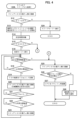
- 4 is a flowchart of a process executed by a CPU 101 of the control device 100.
- 5 is a flowchart showing a continuation of the process shown in FIG. 4 .
- FIG. 5 is a diagram illustrating a modification of the process shown in FIG. 4 .
- FIG. 1 is a diagram corresponding to FIG.
- FIG. 1 diagrammatically illustrating the configuration of a control device 100 according to a second embodiment of the present invention and an air conditioner 400 which is an example of a temperature adjustment device that is an object of control by the control device 100.
- 10 is a diagram corresponding to FIG. 2 and illustrating in more detail the hardware configuration of the control device 100 according to the second embodiment.
- 10A and 10B are diagrams showing examples of screens displayed on an operation panel 120 according to the second embodiment, and correspond to FIG. 3 .
- 10A and 10B are diagrams showing examples of screens displayed on operation panel 120 in a modified example, and correspond to FIG. 9 .
- FIG. 1 shows a schematic configuration of a control device 100 according to a first embodiment of the present invention and an air conditioner 400 which is an example of a temperature adjustment device to be controlled by the control device 100.
- An air conditioning system (hereinafter referred to as "air conditioner") 400 shown in Fig. 1 includes an indoor unit 200 and an outdoor unit 300.
- the indoor unit 200 is usually placed inside a wall 500 of a building, indoors, where the room temperature (temperature of air, which is a gas) should be adjusted.
- the outdoor unit 300 is placed outdoors.
- Fig. 1 mainly shows the configuration of the air conditioner 400 related to temperature adjustment.
- the control device 100 is a device that is additionally installed in the air conditioner 400 and has a function of controlling the operation of a compressor 311 of the air conditioner 400 using an algorithm different from that of the control unit 220 on the air conditioner 400 side.
- the air conditioner 400 includes a refrigerant circuit 410 that spans the indoor unit 200 and the outdoor unit 300.
- the refrigerant circuit 410 is a closed circuit filled with refrigerant, and can be configured, for example, so that the refrigerant circulates to perform a vapor compression refrigeration cycle.
- the refrigerant circuit 410 includes a compressor 311, a four-way valve (four-way switching valve) 312, an outdoor heat exchanger 313, and an expansion valve (pressure reducing valve) 314 on the outdoor unit 300 side, and an indoor heat exchanger 211 on the indoor unit 200 side, which are connected by a refrigerant pipe 310 with the refrigerant sealed inside.
- the compressor 311 has a discharge side connected to a first port P1 of the four-way valve 312, and a suction side connected to a third port P3 of the four-way valve 312.
- the four-way valve 312 connects the first port P1 to the second port P2, and also connects the third port P3 to the fourth port P4.
- the four-way valve 312 connects the first port P1 to the fourth port P4, and also connects the second port P2 to the third port P3, as shown by the imaginary lines in the figure. This forms a path through which the refrigerant discharged from the compressor 311 passes through the indoor heat exchanger 211, the expansion valve 314, and the outdoor heat exchanger 313 in this order, and returns to the suction side of the compressor 311.
- the compressor 311 compresses and discharges the sucked refrigerant.
- Any type of compressor such as a fixed capacity type or a variable capacity type, can be used.
- heat is exchanged between the refrigerant and outdoor air taken in from a ventilation opening 316 by an outdoor fan 321 as indicated by an arrow A.
- the air after the heat exchange is discharged from the ventilation opening 316 as indicated by an arrow B.
- the expansion valve 314 reduces the pressure of the high-pressure liquid refrigerant to a state where it is easy to evaporate, and turns it into a low-pressure liquid refrigerant.
- Any type of expansion valve can be used, such as a capillary tube, a thermostatic expansion valve, or an electronic expansion valve.
- the indoor heat exchanger 211 on the indoor unit 200 side heat is exchanged between the indoor air taken in from the intake port 214 by the indoor fan 212 and the refrigerant.
- the indoor fan 212 for example, rotates an impeller tilted forward in the direction of rotation to draw in air from the intake port 214 as intake C, and releases the air after heat exchange from the exhaust port 215 as exhaust D. In this way, indoor air is taken in by the indoor unit 200, and the air with its temperature, etc., adjusted is expelled into the room.
- the outdoor heat exchanger 313 becomes a condenser (heat radiator) and the indoor heat exchanger 211 becomes an evaporator, performing a refrigeration cycle.
- the refrigerant discharged from the compressor 311 flows to the outdoor heat exchanger 313 and radiates heat to the outdoor air.
- the refrigerant that has radiated heat then expands (reduced in pressure) as it passes through the expansion valve 314 and flows to the indoor heat exchanger 211.
- the indoor heat exchanger 211 the refrigerant absorbs heat from the indoor air and evaporates, and the cooled indoor air is supplied to the room.
- the evaporated refrigerant is sucked into the compressor 311 and compressed.
- the indoor heat exchanger 211 becomes a condenser (heat radiator) and the outdoor heat exchanger 313 becomes an evaporator, performing a refrigeration cycle.
- the refrigerant discharged from the compressor 311 flows into the indoor heat exchanger 211 and radiates heat to the indoor air. This supplies heated indoor air to the room.
- the refrigerant that radiates heat expands (is reduced in pressure) when passing through the expansion valve 314.
- the refrigerant that expands in the expansion valve 314 flows into the outdoor heat exchanger 313 and absorbs heat from the outdoor air to evaporate. The evaporated refrigerant is sucked into the compressor 311 and compressed.
- the operation of each of the above-mentioned parts is controlled by a control unit 220 provided on the indoor unit 200 side.
- the control unit 220 may be a computer equipped with a processor and memory, a dedicated control circuit, or a combination of these.
- the control unit 220 controls the operation of each part of the air conditioner 400 by sending control signals C1 to Cn to each part of the air conditioner 400 based on detection signals from sensors provided in each part of the air conditioner 400, including the indoor unit 200 side and the outdoor unit 300 side. Signal lines (not shown) for transmitting these control signals are wired between the indoor unit 200 and the outdoor unit 300.
- control signal C1 of the compressor 311, the control signal C2 of the outdoor fan 321, the control signal C3 of the four-way valve 312, the control signal C4 of the expansion valve 314, and the control signal C5 of the indoor fan 212 are shown as representatives, but are not limited to these.
- the temperature sensor 213 that is provided near the intake port 214 and detects the temperature of the intake air C is shown as a sensor related to the features of this embodiment, but is not limited to this.
- the wiring is done so that the detection signal Tin of the temperature sensor 213 is input to the Tin terminal of the control unit 220.
- the wiring is done so that the detection signal Tin of the temperature sensor 213 is input to the control device 100, and the control signal Tinx output by the control device 100 is input to the Tin terminal of the control unit 220. The significance of this wiring will be explained in detail later.
- the air conditioner 400 is also configured to be driven by power supplied from an AC power source 510 provided in the building to a power supply circuit 230 provided in the indoor unit 200.
- the power supply circuit 230 appropriately adjusts the voltage and current of the electricity supplied from the AC power source 510, converting it to DC as necessary, and supplies the necessary power to each part of the indoor unit 200.
- the indoor unit 200 and outdoor unit 300 are also connected by a power line (not shown), and the power supply circuit 230 also supplies the necessary power to each part on the outdoor unit 300 side.
- the air conditioner 400 is also provided with a remote controller 240, which is connected to the control unit 220 via a signal line 222.
- a remote controller 240 By operating the remote controller 240, the user can operate the air conditioner 400 by issuing various operational instructions to the control unit 220, such as turning the power on and off, switching between cooling and heating, and setting the set temperatures for cooling and heating.
- the remote controller 240 is driven by a DC power source.
- the power supply circuit 230 supplies DC power to a DC power supply terminal 231 of the indoor unit 200. By connecting the power supply line 241 of the remote controller 240 to this DC power supply terminal 231, the remote controller 240 can receive power from the indoor unit 200 and operate.
- the control device 100 has the function of inputting the detection signals T1 to T3 from the intake temperature sensor 111, the exhaust temperature sensor 112, and the heat exchanger temperature sensor 113, inputting the detection signal E1 indicating the operating state of the power supply circuit 230, and controlling the operation of the compressor 311 provided in the air conditioning device 400 in accordance with these signals.
- the intake air temperature sensor 111 is disposed in an intake section through which the intake air C passes, near the intake port 214 of the indoor unit 200, and is a sensor that detects the temperature of the intake air C.
- the exhaust air temperature sensor 112 is disposed in an exhaust section through which the exhaust air D passes, near the exhaust port 215 of the indoor unit 200, and is a sensor that detects the temperature of the exhaust air D.
- the heat exchanger temperature sensor 113 is a sensor that is provided near or inside the indoor heat exchanger 211 or in contact with the indoor heat exchanger 211 , and detects the temperature of the indoor heat exchanger 211 .
- any type of sensor such as a thermistor, a thermocouple, or an infrared sensor, can be used, whether contact or non-contact.
- a current sensor 114 is installed in the circuit of the power supply circuit 230 that supplies power to each part of the refrigerant circuit 410, to detect whether the power supply circuit 230 is supplying power for cooling or heating operation, i.e., whether cooling or heating is in operation. Conversely, the current sensor 114 is installed at a location in the power supply circuit 230 where such detection is possible.
- the current sensor 114 can be, for example, a magnetic type, but other types may also be used.
- control device 100 is connected to the control unit 220 of the indoor unit 200 via a signal line, and can input a control signal Tinx to the control unit 220 .
- the operation panel 120 is an operation unit for operating the control device 100, and is connected to the control device 100 via an appropriate communication path, which may be wired or wireless.
- control device 100 is an embodiment of the control device of the present invention even when used alone, or when it includes any of the intake air temperature sensor 111, exhaust air temperature sensor 112, heat exchanger temperature sensor 113, and current sensor 114, and signal lines or wireless communication units for connecting to these sensors.
- control device 100 may also include an operation panel 120.
- an air conditioning system including the control device 100 and the air conditioner 400 is an embodiment of a temperature adjustment system of the present invention.
- FIG. 2 is a diagram showing a hardware configuration of the control device 100.
- the control device 100 is a computer including a CPU 101, a memory 102, a communication I/F 103, a notification unit 104, an input/output I/F 105, a SW (switch) control unit 106, and a DIP switch 107, which are connected via a system bus 108.
- the control device 100 also includes a relay switch 109.
- the CPU 101 is a processor that executes programs stored in the memory 102 to realize various functions including the control of the operation panel 120 and the operation control of the compressor 311 .
- the memory 102 is a storage unit that stores programs executed by the CPU 101, various parameters used by the CPU 101, and the like, and also functions as a work memory.
- the communication I/F 103 is an interface for communicating with the operation panel 120, and may be wired or wireless.
- the communication I/F 103 may have a function for communicating with other devices.
- the notification unit 104 has a function of providing various notifications to the user by light, sound, etc., and includes an LED (light emitting diode), a speaker, etc. If the notification function can be provided by the operation panel 120, the notification unit 104 does not need to be provided.
- the input/output I/F 105 has a function of inputting detection signals T1 to T3, E1, and Tin from the various sensors shown in FIG. 1, and outputting a control signal Tinx to the control unit 220.
- the lines corresponding to each of these signals include signal lines for transmitting signals in the direction of the arrows shown in the figure, as well as signal lines for transmitting signals in the opposite direction (such as control signals to the sensors) as necessary, and power supply lines for power supply.
- the SW control unit 106 has a function of controlling the operation of the relay switch 109 .
- the DIP switch 107 is a switch for receiving settings that are not frequently changed and that the user should not touch, among the settings related to the operation of the control device 100. In this example, the DIP switch 107 is used to set on/off a ceiling installation mode, which will be described later.
- the relay switch 109 is a switch that connects terminal a, indicated by a solid line, to the output line of the control signal Tinx when no control signal is supplied (including when the control device 100 itself is not operating), and connects terminal b, indicated by a virtual line, to the output line of the control signal Tinx while a switching signal is being supplied from the SW control unit 106. Switches other than relay type may also be used.
- the detection signal Tin of the temperature sensor 213 equipped in the air conditioner 400 is directly supplied to the output line of the control signal Tinx. As described above, this output line is connected to the Tin terminal of the control unit 220 to which the detection signal Tin should be supplied. Therefore, in this state, the control unit 220 controls the operation of the compressor 311 according to the detection signal Tin of the temperature sensor 213, just as in the state where the control device 100 is not present, and the control device 100 has no effect on the operation of the compressor 311.
- the control device 100 can affect the operation of the compressor 311.
- the control algorithm executed by the control unit 220 is not changed, and a signal indicating a temperature different from the actual detected temperature, which simulates the detection signal Tin of the temperature sensor 213, is input to the control unit 220, thereby indirectly controlling the operation of the compressor 311.
- the controller 220 of almost all models of air conditioners 400 is expected to stop or operate the compressor 311 at a low speed if the temperature detected by the temperature sensor 213 is extremely low (to the extent that an error does not occur), since no further cooling is required. Therefore, if a signal indicating such a temperature detection result is output from the Tinx terminal, the controller 220 can control the compressor 311 to stop or operate at a low speed, regardless of the detected temperature indicated by the detection signal Tin of the temperature sensor 213, thereby stopping or operating the compressor 311 at a low speed.
- the control signal for this purpose is the first control signal (compressor stop signal). In the following description, only the control for stopping the compressor 311 will be described, but similar energy saving is possible even when the compressor is operated at a low speed instead of being stopped.
- the control unit 220 may employ an algorithm that does not immediately start rated operation of the compressor 311 even if the temperature detected by the temperature sensor 213 becomes high. For example, this is because the refrigerant temperature may be low enough that cooling can continue without operating the compressor 311 at rated speed.
- the relay switch 109 when it is desired to operate the compressor 311, the relay switch 109 is switched to the terminal a side, and the compressor 311 is operated in accordance with the original control algorithm of the control unit 220.
- an algorithm may be employed in which the second control signal is used to operate the compressor 311 at the rated speed.
- the compressor 311 can be controlled in a manner opposite to that during cooling operation.
- the controller 220 of almost all models of air conditioners 400 is expected to stop the compressor 311 when the temperature detected by the temperature sensor 213 is extremely high (to the extent that an error does not occur) since no further heating is required. Therefore, if a signal indicating such a temperature detection result is output from the Tinx terminal, the controller 220 can control the compressor 311 to stop, thereby stopping the compressor 311.
- the control signal for this purpose is also the first control signal.
- control unit 220 control compressor 311 to operate, thereby operating compressor 311.
- the control signal for this purpose is also the second control signal. The considerations regarding whether or not to use the second control signal are the same as in the case of cooling operation.
- the current, voltage, waveform, etc. of the first and second control signals can be determined by measuring the characteristics of the temperature sensor 213 when the control device 100 is installed, and stored in the memory 102, and the input/output I/F 105 can then output a signal that matches those characteristics.
- the resistance value of the thermistor constituting the temperature sensor 213 provided in the indoor unit may be measured, and a resistor having a resistance value close to the measured value may be installed in the output path to adjust the characteristics of the first and second control signals.
- a variable resistance function capable of setting the resistance value may be built into the input/output I/F 105.
- the resistance values of thermistors built into air conditioners 400 from different manufacturers vary, and in the case of using resistors in this way, it is necessary to measure the resistance value of the thermistor one by one when installing the control device 100, and install a resistor close to this value.
- the control device 100 described above may be configured to operate by receiving power from an AC power source near the installation location. However, doing so would require a power supply circuit inside the control device 100 to obtain a stable DC current to drive the CPU 101, etc., which would lead to an increase in size and cost.
- the control device 100 is placed near the indoor unit 200, and the indoor unit 200 is provided with a DC power terminal 231 for supplying power to the remote controller 240. Therefore, as shown by the dashed line in FIG. 1, if the control device 100 is configured to receive power from this DC power terminal 231, the internal configuration of the control device 100 can be simplified and the size and costs can be reduced. If there is an extra DC power terminal 231 on the indoor unit 200, the power line can be connected as is, and even if there is no spare, the power line can be branched and connected to both the control device 100 and the remote controller 240.
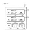
- FIG. 3 is a diagram showing an example of an operation screen 150 displayed on the operation panel 120. As shown in FIG. This operation screen 150 is displayed on a touch panel of the operation panel 120 in response to an instruction transmitted from the CPU 101. Fig. 3 shows a screen for setting the target temperatures for cooling and heating, which is displayed in response to the operation of the setting button 181.
- This operation screen 150 is provided with a cooling temperature setting section 160 and a heating temperature setting section 170.
- the operator can input a desired temperature into input fields 161, 171 using keys or the like displayed in a pop-up display, and operate change buttons 162, 172 to set the target temperatures for cooling and heating.
- This target temperature is referred to by the control device 100 , but it does not have to be the same as the set temperature set by the remote controller 240 and referred to by the control unit 220 of the air conditioner 400 .
- the bypass mode button 182 is a button for toggling on and off the bypass mode in which the relay switch 109 is always connected to terminal a. During bypass mode, the control device 100 has no effect on the operation of the air conditioner 400.
- the data save button 183 is a button for toggling the saving of the operation log of the control device 100 on and off.
- saving is on, for example, the operating time, the time when the relay switch 109 was connected to the terminal b side, the timing when each judgment in FIG. 4 and FIG. 5 became Yes, etc. are saved in the memory 102 as an operation log.
- This operation log can be read out to an external PC or the like via the communication I/F 103.
- the current sensor 114 can be used to detect the total amount of current supplied from the power supply circuit 230 to each part of the air conditioner 400, or the amount of current supplied to the compressor 311, and these current amounts can also be saved as an operation log. Based on this information, the change in energy consumption depending on whether the bypass mode is on or off can be analyzed, and the amount of energy consumption reduction by the control device 100 can be estimated.
- the process shown here is a process according to an embodiment of a temperature adjustment device control method of the present invention.
- the process of each step will be explained as being executed by the control device 100.
- the control device 100 first connects the relay switch 109 to the terminal a side (S11).
- the relay switch 109 is configured to be connected to the terminal a side when no control signal is supplied, so it should be connected to the terminal a side at startup, and the process of step S11 can be omitted.
- the control device 100 determines whether the state of the detection signal E1, which indicates the operating state of the power supply circuit 230, is ON (operating) (S12). If it is not operating, the control device 100 does not need to control the air conditioner 400, so it transitions to sleep mode (S24) and ends the process. It is advisable to monitor the detection signal E1 even during sleep mode, and execute the process of FIG. 4 again if it is ON. In the process of step S12, the CPU 101 functions as an operation detection unit.
- the control device 100 activates each of the temperature sensors 111-113 and starts monitoring the detection signals T1-T3 (S13). It then waits for a predetermined time (S14).
- the predetermined time is set to the time required for the compressor 311 to operate for a sufficient period of time after the air conditioner 400 has not been used for a while and is then turned on, to allow cool air (in cooling mode) or warm air (in heating mode) to be discharged from the exhaust port 215 of the indoor unit 200. This time can be set to, for example, two minutes.
- the predetermined time may be set to a longer time.
- the control device 100 judges whether the detection signal T2 of the exhaust temperature sensor 112 indicates 25° C. or less (S15). If this is Yes, it is determined that the indoor unit 200 is discharging cool air and therefore the air conditioner 400 is performing a cooling operation, and the control device 100 transitions to cooling mode control (first control) (S16) and proceeds to the processing of step S17 and thereafter. If the answer is No in step S15, it is determined that the indoor unit 200 is discharging warm air and therefore the air conditioning device 400 is performing heating operation, and the control device 100 transitions to heating mode control (second control) (S31 in FIG. 5) and proceeds to processing from step S32 onwards.
- first control cooling mode control
- second control heating mode control
- the 25°C used as the standard in step S15 is selected as a temperature higher than the cold air temperature discharged during cooling operation and lower than the warm air temperature discharged during heating operation in most air conditioners 400, regardless of the model, but the specific numerical value is not limited to this.
- air conditioners 400 regardless of the set room temperature for cooling or heating and the actual room temperature, the temperature of the cold air and warm air discharged when the room temperature is relatively stable is usually within a limited range. For this reason, assuming the state after the specified time in step S14 has elapsed, it is usually possible to determine a standard temperature such as the above 25°C. Furthermore, the temperature of the intake air C does not need to be taken into account in the judgment in step S15.
- the control device 100 determines whether or not the temperature indicated by the detection signal T1 from the intake air temperature sensor 111 (i.e., the air temperature in the room in which the indoor unit 200 is installed) has become lower than the cooling target temperature (first target temperature) set on the screen of Figure 3 within a predetermined upper limit time (S17, S18).
- the predetermined upper limit time used in step S17 is set to a time during which the indoor air temperature is considered to sufficiently reach the cooling target temperature, taking into consideration the predetermined time in step S14, even when the air conditioner 400 is turned on after not being used for a while. For example, it may be set to 3 minutes.
- step S17 becomes Yes, and error processing from step S25 onwards is entered. That is, the control device 100 connects the relay switch 109 to the terminal a side (S25), and if the number of consecutive resets is less than a predetermined number, resets and restarts the CPU 101 (S26, S27). A retry is performed in consideration of cases such as when the detection signal from the sensor is not being input normally. If the number of consecutive resets exceeds a predetermined number, the notification unit 104 notifies the operator of the occurrence of an abnormality by light, sound, etc., and ends the processing (S28). In this case, the air conditioning function of the air conditioner 400 is not working normally, or a sensor on the control device 100 side may have failed, so the control device 100 is stopped.
- step S18 the control device 100 stores the temperature T3m indicated by the detection signal T3 from the heat exchanger temperature sensor 113 at that time (S19), and connects the relay switch 109 to terminal b (S20). This causes the above-mentioned first control signal (compressor stop signal) to be output from the Tinx terminal of the input/output I/F 105 to the control unit 220.
- the control unit 220 is expected to stop the compressor 311 when the first control signal is input.
- control device 100 continues to output the compressor stop signal until the temperature indicated by the detection signal T3 from the heat exchanger temperature sensor 113 becomes equal to or higher than T3m+0.5°C (the temperature of T3 rises by equal to or higher than the first threshold value), and thereafter the temperature indicated by the detection signal T2 from the exhaust temperature sensor 112 becomes equal to or higher than the cooling target temperature+0.5°C (the second target temperature) (S21, S22). During this time, the compressor 311 remains stopped.
- step S22 the control device 100 connects the relay switch 109 to the terminal a (S23). This causes the detection signal Tin of the temperature sensor 213 provided in the air conditioner 400 to be input directly to the control unit 220, and the control unit 220 then controls the operation and stop of the compressor 311 according to the original control function of the air conditioner 400. And, since at this point the indoor unit 200 is in a state where it is unable to discharge cold air below the cooling target temperature, it is expected that the control unit 220 will operate the compressor 311 immediately or in the near future, and the discharge of cold air from the indoor unit 200 will resume. Thereafter, the process returns to step S17 and is repeated.
- steps S18 and S20 are intended to forcibly stop the compressor 311 when the indoor air temperature drops to the cooling target temperature, as further cooling is no longer necessary, thereby reducing energy consumption.
- the control algorithm original to the air conditioner 400
- the control device 100 can intervene in this control and stop the compressor 311, thereby reducing energy consumption.
- step S21 essentially determines whether the room temperature is being maintained compared to the time when the compressor 311 was stopped, that is, the time when the room temperature became the cooling target temperature, and if the efficiency of heat absorption has decreased to a certain extent, it will be Yes.
- the "+0.5°C" part can be determined depending on how much of a decrease in heat absorption efficiency is acceptable.
- step S22 the stop of the compressor 311 is released at the point in time when the temperature of the exhaust air D actually exceeds the cooling target temperature (+ ⁇ ) and it becomes impossible to maintain the room temperature at the cooling target temperature without operating the compressor 311. This makes it possible to minimize the time during which the compressor 311 is operated, thereby reducing the energy consumption of the air conditioner 400 .
- the value of + ⁇ is +0.5°C, but it is not limited to this value. If ⁇ is large, it is expected that it will take a long time for the temperature of exhaust D to drop after relay switch 109 is switched over, resulting in large fluctuations in room temperature. On the other hand, if ⁇ is small, the time that compressor 311 is stopped will be short, resulting in less energy saving effect. An appropriate value can be set taking these factors into consideration. There is no prohibition on setting it to a negative value.
- step S21 will be Yes before the judgment in step S22.
- the judgment in step S21 is also made, and the compressor 311 is released from the stopped state after this judgment has become Yes, thereby making it possible to determine the release timing more accurately and achieving greater energy savings.
- the actual room temperature may temporarily become lower than the target cooling temperature due to the remaining cooling capacity. This is a temperature drop that does not meet the user's needs, and consuming energy for this purpose may be considered a waste.
- step S18 by comparing T1 with a value higher than the actual cooling target temperature in step S18, it is believed that it is possible to further reduce energy consumption while keeping the room temperature at the temperature desired by the user. How many degrees higher than the cooling target temperature should be will vary depending on the installation environment of the indoor unit 200 and the outdoor temperature, but it is preferable to set the temperature difference so that the room temperature (T1) just reaches the cooling target temperature at or shortly before step S22 becomes Yes. In many environments, it is expected that this can be achieved with a temperature difference of around 0.5°C to 2°C.
- the control device 100 first determines whether or not the ceiling mounting mode is set (S32).
- the ceiling mounting mode takes into consideration that warm air tends to accumulate at the top when the indoor unit 200 is mounted on the ceiling of a room, and in order to properly determine whether the room temperature has reached the heating target temperature, the intake air temperature is compared with a temperature higher than the heating target temperature in step S36. In other words, when the ceiling mounting mode is set, the third target temperature is set higher than when it is not. Since the installation position of the indoor unit 200 is usually fixed, the ceiling mounting mode can be set by the installer when installing the control device 100, and there is no need to change it thereafter.
- the temperature indicated by the detection signal T1 from the intake air temperature sensor 111 i.e., the air temperature inside the room where the indoor unit 200 is installed
- the heating target temperature third target temperature set on the screen of FIG. 3 within a specified upper limit time (S33, S34).
- the ceiling-mounted mode it is determined whether or not the temperature indicated by the same T1 has reached or exceeded the heating target temperature + 3°C (third target temperature) (S35, S36).
- This value of +3°C is just an example, and an appropriate value can be set based on factors such as the temperature difference between the temperature near the ceiling when the unit is mounted on the ceiling and an appropriate location in the room.
- the predetermined upper limit time used in steps S33 and S35 is set to a time that is considered long enough for the indoor air temperature to reach the heating target temperature, taking into consideration the predetermined time in step S14, even when the air conditioner 400 is turned on after not being used for a while. For example, it may be set to three minutes, but it is not essential to set the same time as in the cooling mode. In either case, if step S34 or S36 does not become Yes within the upper limit time, step S33 or S35 becomes Yes, and the process enters error processing from step S25 onward in FIG. 4, as in the cooling mode.
- step S34 or S36 the control device 100 stores the temperature T3m indicated by the detection signal T3 from the heat exchanger temperature sensor 113 at that time (S37), and connects the relay switch 109 to terminal b (S38). This is the same operation as steps S19 and S20 in the cooling mode, and it is expected that this will cause the control unit 220 to stop the compressor 311.
- the control device 100 continues to output the first control signal (compressor stop signal) until the temperature indicated by the detection signal T3 from the heat exchanger temperature sensor 113 falls below T3m stored in step S37 (the temperature of T3 falls by more than the second threshold value ⁇ 0) and thereafter the temperature indicated by the detection signal T2 from the exhaust temperature sensor 112 falls below the heating target temperature (fourth target temperature) (S39, S40). During this time, the compressor 311 remains stopped.
- step S40 the control device 100 connects the relay switch 109 to the terminal a (S41).
- the control unit 220 controls the operation and stop of the compressor 311 according to the original control function of the air conditioner 400, as in step 23 in the cooling mode.
- the indoor unit 200 is in a state where it is unable to discharge warm air above the heating target temperature, it is expected that the control unit 220 will operate the compressor 311 immediately or in the near future, and the discharge of warm air from the indoor unit 200 will resume. Thereafter, the process returns to step S32 and is repeated.
- steps S34, S36, and S38 are intended to forcibly stop the compressor 311 and reduce energy consumption when the indoor air temperature reaches the heating target temperature and further heating is no longer necessary.
- the control algorithm original to the air conditioner 400
- the control device 100 can intervene in this control and stop the compressor 311, reducing energy consumption.
- step S39 essentially determines whether the room temperature is being maintained compared to the time when the compressor 311 was stopped, i.e., the time when the room temperature became the heating target temperature, and if the heating efficiency has decreased to a certain extent, the answer is Yes. Depending on how much of a decrease in heat absorption efficiency is acceptable, a value slightly smaller than T3m may be used as the comparison target.
- step S40 the stop of the compressor 311 is released at the point in time when the temperature of the exhaust air D actually falls below the heating target temperature and it becomes impossible to maintain the room temperature at the heating target temperature without operating the compressor 311. This makes it possible to minimize the time during which the compressor 311 is operated, thereby reducing the energy consumption of the air conditioner 400 .
- the value to be compared with T2 in step S40 is the heating target temperature itself, but it is not limited to this value.
- the heating target temperature - ⁇ is used as the comparison, it is expected that if ⁇ is large, it will take a long time for the temperature of the exhaust D to rise after the relay switch 109 is switched over, resulting in large fluctuations in room temperature, whereas if ⁇ is small, the time that the compressor 311 is stopped will be short, resulting in less energy saving effect.
- An appropriate value can be set taking these factors into consideration. There is no prohibition on ⁇ being a negative value.
- step S39 will be Yes before the judgment in step S40.
- the reason why the judgment in step S39 is provided despite this, and the reason why it may be omitted, are the same as the judgment in step S21 described in the cooling mode.
- the indoor heat exchanger 211 still has heat dissipation capacity for a while, if the compressor 311 is stopped when the heating target temperature is reached, a temperature rise that does not meet the user's needs will occur, just as in the case of cooling. Then, in the heating mode, by comparing T1 with a value lower than the actual heating target temperature in step S34, it is possible to further reduce energy consumption while keeping the room temperature at the temperature desired by the user. The appropriate temperature difference is the same as in the cooling mode.
- the comparison target in step S36 in the ceiling mounted mode may be a temperature higher than the value in step S34 in the normal mode.
- the control device 100 described above performs the processing shown in Figures 4 and 5, temporarily interrupting the control of the compressor 311 by the control unit 220 in the air conditioner 400, essentially forcibly stopping the compressor 311, and by reducing the operating time of the compressor 311 compared to when the control device 100 is not present, the energy consumption of the air conditioner 400 is reduced.
- control device 100 when installing the control device 100, it is only necessary to place temperature sensors in three places on the indoor unit 200 and connect the input/output I/F 105 so that it interrupts the signal line from the temperature sensor 213 to the control unit 220, and there is no need to modify other parts of the air conditioner 400. For this reason, the control device 100 is easy to install, and the possibility of the installation of the control device 100 causing a malfunction in the air conditioner 400 is extremely low.
- the control device 100 executes steps S51 to S53 in Fig. 6 instead of step S23 when the determination in step S22 in Fig. 4 is Yes. That is, when it is time to operate the compressor 311, instead of causing the control unit 220 to control the compressor 311 according to its original control function, a compressor operation signal is sent to the control unit 220 to control the compressor 311 to operate at a rated speed (S51). At this point, the relay switch 109 is kept connected to the terminal b, and the compressor operation signal is sent from the Tinx terminal of the input/output I/F 105.
- step S51 the process proceeds to step S17 in Fig. 4, and the rated operation of compressor 311 will be continued until the room temperature becomes equal to or lower than the cooling target temperature in step S18.
- step S52 when the room temperature indicated by detection signal T1 from intake air temperature sensor 111 reaches a temperature slightly higher (by positive value X) than the cooling target temperature, relay switch 109 is connected to terminal a (S53), and control unit 220 is returned to a state in which it controls compressor 311 according to its original control function, and then the process proceeds to step S17 in FIG. 4.
- step S18 the compressor operation signal may be sent similarly if the answer is Yes in step S40.
- the determination corresponding to step S52 may be "Is T1 ⁇ the heating target temperature ⁇ X?"
- the second embodiment is an example in which a control device 100 for controlling a compressor 311 is installed in an air conditioner 400 of a type in which a single outdoor unit is shared by a plurality of indoor units.
- a control device 100 for controlling a compressor 311 is installed in an air conditioner 400 of a type in which a single outdoor unit is shared by a plurality of indoor units.
- parts that are common to or correspond to the first embodiment will be designated by the same reference numerals as in the first embodiment, and descriptions of the common parts will be omitted as appropriate.
- FIG. 7 shows a schematic configuration of the control device 100 of the second embodiment and an air conditioner 400, which is an example of a temperature adjustment device that is the target of control by the control device 100.
- FIG. 7 shows only the configuration of the refrigerant circuit 410, the refrigerant pipe 310, the compressor 311, the outdoor heat exchanger 313, and the indoor heat exchangers 211a-211c, and omits illustration of the outdoor fan 321, the indoor fan 212, power supplies, and the wall 500.
- the refrigerant pipe 310 shows a connection during cooling operation, but it is possible to switch between heating and cooling as in the case of FIG. 1.
- the air conditioner 400 in the second embodiment is equipped with three indoor units 200a-200c and one outdoor unit 300, and is configured with a refrigerant circuit 410 that passes sequentially through the outdoor heat exchanger 313 of the outdoor unit 300 and the indoor heat exchangers 211a-211c of each of the indoor units 200a-200c.
- the refrigerant discharged from the compressor 311 and dissipating heat in the outdoor heat exchanger 313 is decompressed and flows to each of the indoor heat exchangers 211a-211c, cooling the intake air C of each of the indoor units 200a-200c.
- Each of the indoor units 200a to 200c is equipped with a control unit 220a to 220c, but of these, only the control unit 220a of the indoor unit 200a is involved in controlling the outdoor unit 300.
- the indoor unit 200a that controls the outdoor unit 300 is often called the parent unit, and the other indoor units 200b and 200c are called child units.
- the control unit 220a of the indoor unit 200a which is the parent unit, transmits control signals C1a to Cna to each part of the air conditioner 400 based on detection signals from sensors provided in each part of the air conditioner 400, including the outdoor unit 300 side on the indoor unit 200a side, to control the operation of each part, like the control unit 220 of the indoor unit 200 in the first embodiment.
- the signals with the second suffix from 1 to (i-1) are signals for controlling the outdoor unit 300 side
- the signals with the suffix from i to n are signals for controlling the indoor unit 200a side.
- the third suffix a indicates that it is an output signal from the control unit 220a.
- Signal lines (not shown) for transmitting these control signals C1a to C(i-1)a are wired between the indoor unit 200a and the outdoor unit 300. Further, a remote controller 240 for operating the air conditioner 400 is connected to the control section 220a of the parent unit.
- the child unit's control units 220b, 220c send control signals Cib-Cnb and Cic-Cnc to each part of the indoor units 200b, 200c based on detection signals from sensors provided in each part of the indoor units 200b, 200c, respectively, to control the operation of each part.
- the subscripts have the same meaning as in the case of the control unit 220a.
- the indoor unit 200a is equipped with a temperature sensor 213a corresponding to the temperature sensor 213 of the first embodiment, and when only the air conditioner 400 is installed, wiring is performed so that the detection signal Tina of the temperature sensor 213a is input to the Tin terminal of the control unit 220a.
- the control device 100 when the control device 100 is installed, wiring is performed so that the detection signal Tina of the temperature sensor 213a is input to the control device 100, and the control signal Tinx output by the control device 100 is input to the Tin terminal of the control unit 220a.
- the meaning of this wiring is the same as in the first embodiment. That is, the control device 100 of the second embodiment is installed so as to supply a control signal to the control unit 220a of the parent unit. This corresponds to the control unit 220a of the parent unit controlling the operation and stop of the compressor 311.
- the child unit also has temperature sensors 213b and 213c corresponding to temperature sensor 213, and their detection signals Tinb and Tinc are input to the Tin terminals of control units 220b and 220c, respectively.
- control units 220b and 220c are not involved in the control of compressor 311, these detection signals Tinb and Tinc do not affect the operation of compressor 311.
- intake air temperature sensor 111a As temperature sensors to be connected to the control device 100, first, intake air temperature sensor 111a, exhaust air temperature sensor 112a, and heat exchanger temperature sensor 113a similar to the temperature sensors 111-113 of the first embodiment are installed in the indoor unit 200a, which is the parent unit, and detection signals T1a-T3a are input.
- intake air temperature sensors 111b, 111c, exhaust air temperature sensors 112b, 112c, and heat exchanger temperature sensors 113b, 113c are installed in the corresponding positions in the indoor units 200b, 200c, which are child units, respectively, and detection signals T1b-T3b, T1c-T3c are input to the control device 100.
- a human presence sensor 130 that detects whether a person is present near any indoor unit by infrared rays, ultrasonic waves, or the like is also connected to the control device 100, and a detection signal H1 is input thereto.
- the human presence sensor 130 is not essential.
- FIG. 8 shows a hardware configuration of the control device 100 according to the second embodiment.
- the input/output I/F 105 has a function of inputting detection signals T1a to T3c, E1 (see FIG. 1), H1, and Tina from the various sensors shown in FIG. 7, and outputting a control signal Tinx to the control unit 220a.
- the input/output I/F 105 includes a selector for selecting which of T1a to T3a, T1b to T3b, or T1a to T3c to use as the temperature sensor detection signal when the control device 100 executes the processes shown in FIGS. 4 and 5, in other words, for selecting which of the indoor units the detected temperature of the temperature sensor to use.
- the other hardware configuration is similar to that described in the first embodiment with reference to FIG.
- FIG. 9 is a diagram showing an example of an operation screen 150 displayed on the operation panel 120. As shown in FIG. This operation screen 150 differs from the example shown in FIG. 3 only in that a temperature reference setting section 190 is added.
- the temperature reference setting section 190 is provided with a window-side button 191, a center button 192, a wall-side button 193, and an automatic button 194, and only one of these can be turned on.
- the window-side button 191, the center button 192, and the wall-side button 193 are buttons for manually selecting which of the three indoor units 200a to 200c the control device 100 will use to control the operation of the compressor based on the temperature of the temperature sensor installed therein. For example, if indoor unit 200a is installed by a window in the room, indoor unit 200b is installed in the center of the room, and indoor unit 200c is installed by a wall in the room, it is thought that during the day, the room temperature on the wall side is more likely to drop due to air conditioning, and the temperature sensor installed in indoor unit 200c will tend to output a lower temperature than the temperature sensor installed in indoor unit 200a.
- the automatic button 194 is a button for setting the control to be performed based on the temperature detected by the temperature sensor of the indoor unit in the location with the most people, based on the detection signal from the human presence sensor 130. By using this control, it is possible to perform air conditioning that is comfortable for many people in the room, while saving energy as much as possible within that range.
- control device 100 of the second embodiment executes the processing of Figures 4 and 5 based on the detected temperature of a temperature sensor installed in a selected one of the three indoor units 200a to 200c, so that even in an air conditioning device 400 of a type in which a single outdoor unit 300 is shared by multiple indoor units 200a to 200c, it is possible to maintain the room temperature at a set temperature while reducing the operating time of the compressor 311, thereby achieving energy savings. It is also possible to execute the processes in Figures 4 and 5 using the average values of temperatures detected by the temperature sensors of all indoor units or a number of arbitrarily selected indoor units, rather than a single specific indoor unit. In this way, control can be performed based on the average indoor conditions.
- FIG. 10 This concludes the explanation of the embodiment, but in this invention, the specific configuration of the device or system, specific processing procedures, parameter values, sensor placement, use and configuration of the temperature adjustment device, etc. are not limited to those described in the embodiment.
- the control device 100 does not need to be able to control both the cooling mode and the heating mode, and may be configured to perform only one of the two modes corresponding to the air conditioner 400 to be controlled. In other words, the judgment in step S15 in FIG. 4 is not necessary.
- control device 100 automatically switches between the heating mode and the cooling mode, but the mode may be set manually. In this case, the determination in step S15 in FIG. 4 is also unnecessary. Also, it is not essential to provide the ceiling installation mode. In the heating mode, the temperature to be compared with T1 may be only one, as in steps S34 and S36 in Fig. 5. In this case, it is conceivable to adopt a temperature intermediate between steps S34 and S36, but this is not limiting.
- step S21 in FIG. 4 or step S39 in FIG. 5 there is no need to install the heat exchanger temperature sensor 113.
- the values of the temperature and other criteria shown in FIG. 4 and FIG. 5 are merely examples, and the values are not limited to those used in the explanation.
- the setting of the target temperature for heating and cooling in the control device 100 by the operation panel 120 is performed independently of the setting of the heating and cooling set temperature on the air conditioner 400 side by the remote colon and roller 240.
- the control device 100 it is also possible for the control device 100 to detect the set temperature signal from the remote colon and roller 240 and automatically make the target temperature on the control device 100 side track the set temperature indicated by the set temperature signal (the set temperature on the air conditioner 400 side). This prevents the set temperatures on the air conditioner 400 side and the control device 100 side from being set to temperatures that are far apart, and prevents a situation in which the control of the control device 100 does not function properly due to differences in set temperatures.
- buttons 163, 173 can be added to the cooling temperature setting section 160 and the heating temperature setting section 170 on the operation screen 150, respectively, so that these buttons can be used to toggle on and off automatic tracking of the target temperature for cooling and heating, respectively.
- control device 100 is configured as a device that is retrofitted to the air conditioner 400, but a control unit that performs control similar to that of the control device 100 may be built into the air conditioner 400 from the beginning.
- the sending of the compressor stop signal in Figures 4 and 5 can be thought of as a forced stop of the compressor 311, and the connection to the terminal a side of the relay switch 109 as switching between operation and stop of the compressor 311 based on the temperature detected by the temperature sensor 213.
- the temperature sensor referenced by the control device 100 in the processing of Figures 4 and 5 is provided separately from the temperature sensor that the indoor unit 200 comes standard with.
- the temperature sensor 213 and the intake air temperature sensor 111 are located in the same position and have the same measurement target. Therefore, if the control device 100 is capable of controlling the temperature sensor 213 and can properly grasp the correspondence between the detection signal and the detected temperature, it is also conceivable that the control device 100 can perform the processing of Figures 4 and 5 by referring to the detection signal of the temperature sensor 213 that comes standard with the indoor unit 200. If the indoor unit 200 has another usable sensor, it may be substituted in a similar manner.
- control device 100 in addition, in the above embodiment, an example was described in which the object to be controlled by the control device 100 was an air conditioner, but the present invention is not limited to this.
- a similar control device 100 can also be used to control the operation of compressors in temperature adjustment devices that use a compressor and a heat exchanger to cool or heat gas, such as refrigerators, freezers, heat retention devices, and heating devices.
- the temperature adjustment device may be a device that performs only one of cooling and heating. In this case, the gas to be temperature-adjusted does not need to be in a closed space such as a room. Naturally, open refrigerators and the like can also be controlled.
- a program embodiment of the present invention is a program for causing a computer to control required hardware to realize the functions of the control device 100 in the above-described embodiment.
- a program may be stored in a ROM or other non-volatile storage medium (flash memory, EEPROM, etc.) that is included in the computer from the beginning.
- flash memory flash memory
- EEPROM electrically erasable programmable read-only memory
- it may also be provided by recording it on any non-volatile recording medium such as a memory card, CD, DVD, or Blu-ray disc.
Landscapes
- Engineering & Computer Science (AREA)
- Chemical & Material Sciences (AREA)
- Combustion & Propulsion (AREA)
- Mechanical Engineering (AREA)
- General Engineering & Computer Science (AREA)
- Signal Processing (AREA)
- Physics & Mathematics (AREA)
- Fuzzy Systems (AREA)
- Mathematical Physics (AREA)
- Thermal Sciences (AREA)
- Air Conditioning Control Device (AREA)
Abstract
La présente invention comprend : un capteur de température d'air d'admission (111) qui est agencé dans une unité d'admission d'air d'une unité intérieure (200) d'un dispositif de climatisation (400) servant de dispositif de réglage de température et qui détecte la température du gaz aspiré ; et un capteur de température de gaz d'échappement (112) qui est agencé dans une unité d'échappement et qui détecte la température du gaz évacué, après qu'une période de temps prescrite ou plus s'est écoulée depuis le début du fonctionnement du dispositif de climatisation (400), lorsque la température détectée par le capteur de température d'air d'admission (111) atteint une première température cible prescrite ou moins, un premier signal de commande pour amener l'unité de commande (220) de l'unité intérieure (200) à effectuer une commande pour arrêter un compresseur (311) étant délivré à l'unité de commande (220), puis la sortie du premier signal de commande à l'unité de commande (220) étant arrêtée lorsque la température détectée par le capteur de température de gaz d'échappement (112) atteint une seconde température cible ou plus. Ainsi, il est possible de commander de manière appropriée le fonctionnement du compresseur dans le dispositif de réglage de température et de réduire la consommation d'énergie tout en supprimant tout effet sur une fonction de réglage de température.
Priority Applications (2)
| Application Number | Priority Date | Filing Date | Title |
|---|---|---|---|
| CN202480032375.8A CN121100256A (zh) | 2023-06-05 | 2024-05-30 | 控制装置、温度调节系统、温度调节装置的控制方法及程序 |
| US19/409,934 US20260092718A1 (en) | 2023-06-05 | 2025-12-05 | Control device, temperature adjustment system, temperature adjustment device control method, and storage medium |
Applications Claiming Priority (4)
| Application Number | Priority Date | Filing Date | Title |
|---|---|---|---|
| JP2023-092792 | 2023-06-05 | ||
| JP2023092792A JP7522491B1 (ja) | 2023-06-05 | 2023-06-05 | 制御装置、温度調整システム、温度調整装置の制御方法及びプログラム |
| JP2023-092793 | 2023-06-05 | ||
| JP2023092793A JP2024174774A (ja) | 2023-06-05 | 2023-06-05 | 制御装置、温度調整システム、温度調整装置の制御方法及びプログラム |
Related Child Applications (1)
| Application Number | Title | Priority Date | Filing Date |
|---|---|---|---|
| US19/409,934 Continuation US20260092718A1 (en) | 2023-06-05 | 2025-12-05 | Control device, temperature adjustment system, temperature adjustment device control method, and storage medium |
Publications (1)
| Publication Number | Publication Date |
|---|---|
| WO2024253020A1 true WO2024253020A1 (fr) | 2024-12-12 |
Family
ID=93795971
Family Applications (1)
| Application Number | Title | Priority Date | Filing Date |
|---|---|---|---|
| PCT/JP2024/019918 Ceased WO2024253020A1 (fr) | 2023-06-05 | 2024-05-30 | Dispositif de commande, système de réglage de température, procédé de commande de dispositif de réglage de température et programme |
Country Status (3)
| Country | Link |
|---|---|
| US (1) | US20260092718A1 (fr) |
| CN (1) | CN121100256A (fr) |
| WO (1) | WO2024253020A1 (fr) |
Citations (7)
| Publication number | Priority date | Publication date | Assignee | Title |
|---|---|---|---|---|
| JPS5767735A (en) * | 1980-10-13 | 1982-04-24 | Toshiba Corp | Air conditioner |
| JPS5956035A (ja) * | 1982-09-20 | 1984-03-31 | Matsushita Electric Ind Co Ltd | 空気調和機の能力制御方法 |
| JPS60134133A (ja) * | 1983-12-23 | 1985-07-17 | Matsushita Electric Ind Co Ltd | 空気調和機の運転制御方法 |
| JPH04270854A (ja) * | 1991-02-26 | 1992-09-28 | Hitachi Ltd | 空気調和機の制御方法 |
| JPH05231704A (ja) * | 1992-02-21 | 1993-09-07 | Mitsubishi Electric Corp | 空気調和機の制御装置 |
| JPH05280792A (ja) * | 1992-04-01 | 1993-10-26 | Matsushita Refrig Co Ltd | 空気調和機 |
| JP2005003329A (ja) * | 2003-06-13 | 2005-01-06 | Ionasu Technologies:Kk | 温度調節機の電力制御方法及び装置 |
-
2024
- 2024-05-30 WO PCT/JP2024/019918 patent/WO2024253020A1/fr not_active Ceased
- 2024-05-30 CN CN202480032375.8A patent/CN121100256A/zh active Pending
-
2025
- 2025-12-05 US US19/409,934 patent/US20260092718A1/en active Pending
Patent Citations (7)
| Publication number | Priority date | Publication date | Assignee | Title |
|---|---|---|---|---|
| JPS5767735A (en) * | 1980-10-13 | 1982-04-24 | Toshiba Corp | Air conditioner |
| JPS5956035A (ja) * | 1982-09-20 | 1984-03-31 | Matsushita Electric Ind Co Ltd | 空気調和機の能力制御方法 |
| JPS60134133A (ja) * | 1983-12-23 | 1985-07-17 | Matsushita Electric Ind Co Ltd | 空気調和機の運転制御方法 |
| JPH04270854A (ja) * | 1991-02-26 | 1992-09-28 | Hitachi Ltd | 空気調和機の制御方法 |
| JPH05231704A (ja) * | 1992-02-21 | 1993-09-07 | Mitsubishi Electric Corp | 空気調和機の制御装置 |
| JPH05280792A (ja) * | 1992-04-01 | 1993-10-26 | Matsushita Refrig Co Ltd | 空気調和機 |
| JP2005003329A (ja) * | 2003-06-13 | 2005-01-06 | Ionasu Technologies:Kk | 温度調節機の電力制御方法及び装置 |
Also Published As
| Publication number | Publication date |
|---|---|
| CN121100256A (zh) | 2025-12-09 |
| US20260092718A1 (en) | 2026-04-02 |
Similar Documents
| Publication | Publication Date | Title |
|---|---|---|
| JP5405076B2 (ja) | 空調冷凍システム | |
| US6829903B2 (en) | Air conditioner and method for operating air conditioner in cooling mode | |
| WO2022002286A1 (fr) | Appareil de conditionnement d'air et procédé de commande associé | |
| CN109798644B (zh) | 控制方法和空调系统 | |
| US20120117995A1 (en) | Energy Saving Device And Method For Cooling And Heating Apparatus | |
| JP2024174774A (ja) | 制御装置、温度調整システム、温度調整装置の制御方法及びプログラム | |
| CN101240933B (zh) | 多系统空调及用于控制所述多系统空调的方法 | |
| KR102866080B1 (ko) | 공기조화기 | |
| KR20040003707A (ko) | 에어컨의 압축기 주파수 제어방법 | |
| JP7522491B1 (ja) | 制御装置、温度調整システム、温度調整装置の制御方法及びプログラム | |
| WO2024253020A1 (fr) | Dispositif de commande, système de réglage de température, procédé de commande de dispositif de réglage de température et programme | |
| JP2000111120A (ja) | 外気温検出機能を備えた空調室外機 | |
| JP3884388B2 (ja) | 冷蔵装置の温度制御方法及び冷蔵装置の運転制御装置 | |
| JP3526393B2 (ja) | 空気調和機 | |
| KR20060124960A (ko) | 공기조화기의 냉방 운전 방법 | |
| KR20220095071A (ko) | 공기 조화기 및 그 제어 방법 | |
| CN120627352B (zh) | 空调器 | |
| KR102817029B1 (ko) | 공기조화기 | |
| CN112834889A (zh) | 空调室外机中的平滑用电容的寿命预测装置及寿命预测方法 | |
| CN119085027B (zh) | 空调 | |
| US20250271190A1 (en) | Compressor control process for variable cascade refrigeration system | |
| KR100487779B1 (ko) | 공기조화기의 운전제어방법 | |
| KR102534198B1 (ko) | 냉동기와 냉각탑 운전비 절감제어를 갖는 냉각탑 | |
| US20250341336A1 (en) | Air conditioner and method for controlling same | |
| US20260029151A1 (en) | Air conditioner and controlling method thereof |
Legal Events
| Date | Code | Title | Description |
|---|---|---|---|
| 121 | Ep: the epo has been informed by wipo that ep was designated in this application |
Ref document number: 24819250 Country of ref document: EP Kind code of ref document: A1 |
|
| WWE | Wipo information: entry into national phase |
Ref document number: 2501008294 Country of ref document: TH |
|
| NENP | Non-entry into the national phase |
Ref country code: DE |
|
| WWE | Wipo information: entry into national phase |
Ref document number: 11202508139S Country of ref document: SG |
|
| WWP | Wipo information: published in national office |
Ref document number: 11202508139S Country of ref document: SG |