WO2024253023A1 - Dispositif d'alimentation en liquide et dispositif d'impression équipé de celui-ci - Google Patents
Dispositif d'alimentation en liquide et dispositif d'impression équipé de celui-ci Download PDFInfo
- Publication number
- WO2024253023A1 WO2024253023A1 PCT/JP2024/019960 JP2024019960W WO2024253023A1 WO 2024253023 A1 WO2024253023 A1 WO 2024253023A1 JP 2024019960 W JP2024019960 W JP 2024019960W WO 2024253023 A1 WO2024253023 A1 WO 2024253023A1
- Authority
- WO
- WIPO (PCT)
- Prior art keywords
- pressure
- supply
- recovery
- ink
- tank
- Prior art date
- Legal status (The legal status is an assumption and is not a legal conclusion. Google has not performed a legal analysis and makes no representation as to the accuracy of the status listed.)
- Ceased
Links
Images




Classifications
-
- B—PERFORMING OPERATIONS; TRANSPORTING
- B41—PRINTING; LINING MACHINES; TYPEWRITERS; STAMPS
- B41J—TYPEWRITERS; SELECTIVE PRINTING MECHANISMS, i.e. MECHANISMS PRINTING OTHERWISE THAN FROM A FORME; CORRECTION OF TYPOGRAPHICAL ERRORS
- B41J2/00—Typewriters or selective printing mechanisms characterised by the printing or marking process for which they are designed
- B41J2/005—Typewriters or selective printing mechanisms characterised by the printing or marking process for which they are designed characterised by bringing liquid or particles selectively into contact with a printing material
- B41J2/01—Ink jet
- B41J2/17—Ink jet characterised by ink handling
- B41J2/175—Ink supply systems ; Circuit parts therefor
-
- B—PERFORMING OPERATIONS; TRANSPORTING
- B41—PRINTING; LINING MACHINES; TYPEWRITERS; STAMPS
- B41J—TYPEWRITERS; SELECTIVE PRINTING MECHANISMS, i.e. MECHANISMS PRINTING OTHERWISE THAN FROM A FORME; CORRECTION OF TYPOGRAPHICAL ERRORS
- B41J2/00—Typewriters or selective printing mechanisms characterised by the printing or marking process for which they are designed
- B41J2/005—Typewriters or selective printing mechanisms characterised by the printing or marking process for which they are designed characterised by bringing liquid or particles selectively into contact with a printing material
- B41J2/01—Ink jet
- B41J2/17—Ink jet characterised by ink handling
- B41J2/18—Ink recirculation systems
Definitions
- This disclosure relates to a liquid supply device and a recording device equipped with the same.
- the inkjet printer is equipped with an ejection head that ejects ink onto a recording medium (printing medium), and a liquid supply device (ink supply device) that supplies ink to the ejection head.
- the liquid supply device is equipped with a supply tank that stores liquid to be supplied to the ejection head, a recovery tank that stores liquid recovered from the ejection head, a circulation pump that returns ink in the recovery tank to the supply tank, a supply-side negative pressure supply unit consisting of a negative pressure pump or the like that applies negative pressure to the supply tank, and a recovery-side negative pressure supply unit consisting of a negative pressure pump or the like that applies negative pressure to the recovery tank.
- the supply side negative pressure supply unit and the recovery side negative pressure supply unit are controlled so that a predetermined pressure difference occurs between the supply tank and the recovery tank. This pressure difference causes ink to move from the supply tank to the recovery tank via the ejection head. The moved ink is returned from the recovery tank to the supply tank by the circulation pump.
- a liquid supply device includes a supply tank that stores liquid to be supplied to a liquid ejection head, and a pressure device that supplies positive pressure to the supply tank via gas so that the inside of the supply tank is at a positive pressure higher than atmospheric pressure.
- the pressure device includes a supply-side regulator that restricts the flow of gas sent from a predetermined pressure source so that the pressure of the gas is reduced, a pressure tube that connects the supply-side regulator and the supply tank so that the gas after being reduced in pressure by the supply-side regulator is sent to the supply tank, and a branch tube that branches off from the middle of the pressure tube and extends with an end that is open to the atmosphere.
- a recording device includes the above-mentioned liquid supply device that supplies ink as the liquid, and the liquid ejection head that ejects the ink supplied from the liquid supply device onto a predetermined recording medium.
- FIG. 1 is a perspective view illustrating the overall configuration of an inkjet printer according to an embodiment of the present disclosure.
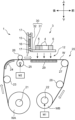
- 2 is a schematic cross-sectional view taken along line II-II in FIG. 1.
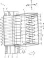
- FIG. 2 is an enlarged oblique view of a carriage of the inkjet printer.
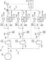
- 2 is a system diagram illustrating a schematic configuration of a liquid supply device mounted on the carriage.
- FIG. 4 is a system diagram showing a mechanical and electrical configuration of a pressurizing device in the liquid supply apparatus.
- FIG. 4 is a system diagram showing a mechanical and electrical configuration of a pressure reducing device in the liquid supply apparatus.
- FIG. FIG. 2 is a schematic diagram showing a configuration of a pressurizing pipe and a branch pipe in the pressurizing device.
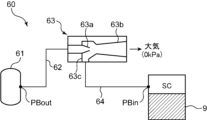
- 3 is a schematic diagram showing a structure of a vacuum ejector in the pressure reducing device.
- FIG. FIG. 2 is a perspective view showing a layout of the pressurizing pipe and the branch pipe.
- an inkjet printer equipped with an ink head that ejects ink for forming an image onto a wide, long recording medium will be exemplified as a specific example of a recording device.
- Inkjet printers are suitable for digital textile printing, which uses an inkjet method to print images such as letters and patterns onto a recording medium made of fabric such as woven or knitted fabric.
- the recording device according to the present disclosure can also be used to print various images onto recording media such as paper sheets and resin sheets.
- FIG. 1 is a perspective view showing the overall configuration of an inkjet printer 1 according to an embodiment of the present disclosure
- FIG. 2 is a schematic cross-sectional view taken along line II-II in FIG. 1.
- the inkjet printer 1 is a printer that prints images on a wide and long workpiece W (recording medium) using an inkjet method. As an example, the width of the workpiece W is several meters.
- the printer 1 includes a device frame 10, and a work transport unit 20 and a carriage 3 that are incorporated into the device frame 10. Note that in this embodiment, the left-right direction is the main scanning direction S ( FIG. 3 ) when printing on the workpiece W, and the direction from the rear to the front is the sub-scanning direction (the transport direction F of the workpiece W, which intersects with the main scanning direction S).
- the device frame 10 forms a framework for mounting various components of the inkjet printer 1.
- the work transport unit 20 is a mechanism that intermittently feeds (transports) the work W so that the work W progresses in a transport direction F from rear to front in the printing area where the inkjet printing process is performed.
- the carriage 3 is equipped with an ink head 4, a pre-treatment liquid head 5 (FIG. 3), a post-treatment liquid head 6, and a liquid supply device 7, and moves back and forth in a main scanning direction S (left-right direction) that intersects with the transport direction F of the work W during the inkjet printing process.
- the ink head 4 corresponds to the "liquid ejection head" in this disclosure.
- the device frame 10 includes a central frame 111, a right frame 112, and a left frame 113.
- the central frame 111 forms a framework for mounting various components of the inkjet printer 1, and has a left-right width corresponding to the work transport section 20.
- the right frame 112 and the left frame 113 are erected to the right and left of the central frame 111, respectively. Between the right frame 112 and the left frame 113 is the printing area 12 where printing processing is performed on the work W.
- the right frame 112 forms the maintenance area 13.
- the maintenance area 13 is an area where the carriage 3 is retracted when the printing process is not being performed.
- cleaning and purging processes are performed on the nozzles (ejection holes) of the ink head 4, pre-treatment liquid head 5 and post-treatment liquid head 6, and caps are also fitted.
- the left frame 113 forms the turn-around area 14 for the carriage 3.
- the turn-around area 14 is an area where the carriage 3 temporarily enters when it performs a main scan in the opposite direction after performing a main scan in the opposite direction from right to left in the printing process.
- a carriage guide 15 is attached to the upper side of the device frame 10 to allow the carriage 3 to move back and forth in the left-right direction.
- the carriage guide 15 is a flat member that is long in the left-right direction, and is disposed above the work transport section 20.
- a timing belt 16 is attached to the carriage guide 15 so that it can move in a circular motion in the left-right direction (main scanning direction).
- the timing belt 16 is an endless belt that is driven to move in a circular motion in the left or right direction.
- the carriage guide 15 is equipped with a pair of upper and lower guide rails 17 that extend parallel to the left and right and that hold the carriage 3 in a state in which it can move back and forth in the main scanning direction S.
- the carriage 3 engages with the guide rails 17.
- the carriage 3 is also fixed to a timing belt 16. As the timing belt 16 moves orbitally to the left or right, the carriage 3 moves left or right along the carriage guide 15 while being guided by the guide rails 17.
- the work transport section 20 includes a feed roller 21 that pays out the work W before printing, and a take-up roller 22 that takes up the work W after printing.
- the feed roller 21 is located at the rear lower part of the device frame 10, and is a take-up shaft for the feed roll WA, which is a wound body of the work W before printing.
- the take-up roller 22 is located at the front lower part of the device frame 10, and is a take-up shaft for the take-up roll WB, which is a wound body of the work W after the printing process.
- a first motor M1 is attached to the take-up roller 22, which drives the take-up roller 22 to rotate around its axis and perform the winding operation of the work W.
- the path between the delivery roller 21 and the take-up roller 22 and passing through the printing area 12 is the transport path for the work W.
- a first tension roller 23 applies a predetermined tension to the work W on the upstream side of the transport roller 25.
- the work guide 24 changes the transport direction of the work W from upward to forward, allowing the work W to enter the printing area 12.
- the transport roller 25 is a roller that generates a transport force that intermittently feeds the workpiece W in the printing area 12.
- the transport roller 25 is driven to rotate about its axis by the second motor M2, and intermittently transports the workpiece W forward (predetermined transport direction F) so that the workpiece W passes through the printing area 12 (image forming position) facing the carriage 3.
- the pinch roller 26 is disposed to face the transport roller 25 from above, and forms a transport nip portion with the transport roller 25.
- the turn-back roller 27 changes the transport direction of the work W that has passed through the printing area 12 from the forward direction to the downward direction, and guides the work W after the printing process to the take-up roller 22.
- the second tension roller 28 applies a predetermined tension to the work W downstream of the transport roller 25.
- a platen 29 is disposed below the transport path of the work W in the printing area 12.
- the carriage 3 is supported at one end by the guide rail 17 and moves back and forth in the main scanning direction S (left and right in this embodiment) that intersects (orthogonal in this embodiment) with the transport direction F.
- the carriage 3 comprises a carriage frame 30, and an ink head 4, a pre-treatment liquid head 5, a post-treatment liquid head 6, and a liquid supply device 7 that are mounted on the carriage frame 30.
- the carriage frame 30 includes a head support frame 31 and a back frame 32.
- the head support frame 31 is a horizontal plate that holds the heads 4 to 6 described above.
- the back frame 32 is a vertical plate that extends upward from the rear edge of the head support frame 31.
- the timing belt 16 is fixed to the back frame 32.
- the guide rail 17 is engaged with the back frame 32. That is, in this embodiment, the back frame 32 is an engagement portion that holds the guide rail 17 in a cantilevered state.
- the head support frame 31 is a horizontal plate whose rear end side is supported in a cantilevered state on the guide rail 17 by the engagement portion described above.
- the cantilevered state refers to a state in which the engagement portion (back frame 32), which is the portion of the carriage 3 that is held by the guide rail 17, which is a holding member, is present only on one side, either upstream or downstream, from the center of the carriage 3 in the transport direction F, and no other engagement portion is present on the opposite side to the side where the engagement portion is present.
- the engagement portion may also be located outside the range in which the ink head 4 and processing head are located in the transport direction F. In other words, the engagement portion may be located only upstream or only downstream of the range in which the ink head 4 and processing head are located in the transport direction F.
- Fig. 3 is an enlarged perspective view of the carriage 3 shown in Fig. 1.
- Fig. 3 shows a transport direction F (sub-scanning direction) of the work W and a main scanning direction S which is a moving direction of the carriage 3.
- Fig. 3 shows an example in which a plurality of ink heads 4 which eject ink for image formation onto the work W, a pre-treatment liquid head 5 and a post-treatment liquid head 6 which eject a non-coloring treatment liquid, and a liquid supply device 7 which supplies the ink and treatment liquid to these heads 4 to 6 are mounted on the carriage 3.
- Each of the ink heads 4 has a number of nozzles (ink ejection holes) that eject ink droplets by an ejection method such as a piezoelectric method using a piezoelectric element or a thermal method using a heating element, and an ink passage that guides the ink to the nozzles.
- nozzles ink ejection holes
- an ejection method such as a piezoelectric method using a piezoelectric element or a thermal method using a heating element
- an ink passage that guides the ink to the nozzles.
- a water-based pigment ink containing a water-based solvent, pigment, and binding resin (binder) can be used as the ink.
- the multiple ink heads 4 in this embodiment are capable of ejecting eight colors of ink.
- the ink heads 4 are mounted on the head support frame 31 of the carriage 3 so as to be aligned in two rows in the main scanning direction S. Each color ink head 4 has two heads.
- the ink heads 4 include a first upstream ink head 41A and a first downstream ink head 42A. These ink heads 4 eject yellow ink.
- the ink heads 4 also include a second upstream ink head 41B and a second downstream ink head 42B. These ink heads 4 eject magenta ink.
- two ink heads 4 that eject ink of the same color are arranged at positions offset from each other in the transport direction F and the main scanning direction S. These two ink heads 4 are considered as one set, and a total of eight sets of ink heads 4 (41A to 41H, 42A to 42H) eject ink of different colors.
- the ink heads 4 include a first upstream ink head 41A to an eighth upstream ink head 41H and a first downstream ink head 42A to an eighth downstream ink head 42H.
- first upstream ink head 41A to the eighth upstream ink head 41H are referred to without distinction, they may be simply referred to as upstream ink head 41.
- first downstream ink head 42A to the eighth downstream ink head 42H may be simply referred to as downstream ink heads 42.
- the pre-treatment liquid head 5 and the post-treatment liquid head 6 are disposed at positions different from the ink head 4 in the transport direction F.
- the pre-treatment liquid head 5 is disposed upstream of the ink head 4 in the transport direction F.
- FIG. 3 shows an example in which one pre-treatment liquid head 5 is disposed near the left end of the array of ink heads 4.
- the post-treatment liquid head 6 is disposed downstream of the ink head 4 in the transport direction F.
- FIG. 3 shows an example in which one post-treatment liquid head 6 is disposed at the right end of the array of ink heads 4.
- multiple pre-treatment liquid heads 5 or multiple post-treatment liquid heads 6 may be disposed. It is desirable that the carriage 3 is provided with at least one pre-treatment liquid head 5 and at least one post-treatment liquid head 6, but in other embodiments, the pre-treatment liquid head 5 and the post-treatment liquid head 6 may not be disposed.
- the series of heads arranged along the main scanning direction S, which is made up of the ink heads 4, pretreatment liquid heads 5, and posttreatment liquid heads 6, is referred to as a row of heads, or simply as a row.
- the series of heads arranged along the transport direction F, which is made up of the ink heads 4, pretreatment liquid heads 5, and posttreatment liquid heads 6, is referred to as a row of heads, or simply as a row.
- the pretreatment liquid head 5 ejects pretreatment liquid for performing a predetermined pretreatment on the workpiece W.
- the pretreatment liquid is ejected from the ink head 4 onto a position on the workpiece W where ink has not yet been ejected from the ink head 4.
- the pretreatment liquid is a non-coloring treatment liquid that does not develop color even when it adheres to the workpiece W, and is a treatment liquid that exhibits functions such as increasing the fixation of ink to the workpiece W and the coagulation of ink pigments.
- a treatment liquid in which a binder resin is mixed into a solvent, or a treatment liquid in which a positively charged cationic resin is mixed into a solvent can be used.
- the post-treatment liquid head 6 ejects post-treatment liquid for performing a predetermined post-treatment on the workpiece W to which ink has been attached.
- the post-treatment liquid is ejected from the post-treatment liquid head 6 to a position on the workpiece W after the ink has been ejected from the ink head 4.
- the post-treatment liquid is a non-coloring treatment liquid that does not develop color even when it adheres to the workpiece W, and has the function of increasing the fixation and robustness (resistance to rubbing and scraping) of the ink image printed on the workpiece W by the ink head 4.
- a silicone-based treatment liquid or the like can be used as such a post-treatment liquid.
- the post-treatment liquid and the pre-treatment liquid are different treatment liquids. Specifically, the post-treatment liquid and the pre-treatment liquid contain different components.
- non-color-forming processing liquid refers to a liquid that, when printed alone on a recording medium, is not recognized as having color by the naked eye.
- Colors here include colors with a saturation of zero, such as black, white, and gray.
- Non-color-forming processing liquids are basically transparent liquids, but for example, when looking at 1 liter of processing liquid in liquid form, it is not completely transparent and may appear slightly white. Such colors are very light, so when printed alone on a recording medium, it is not recognized as having color by the naked eye. Note that, depending on the type of processing liquid, when printed alone on a recording medium, changes such as the appearance of gloss on the recording medium may occur, but this state is not color-forming.
- the pre-treatment liquid and the post-treatment liquid may be ejected onto substantially the entire surface of the workpiece W.
- the pre-treatment liquid and the post-treatment liquid may be ejected selectively in accordance with the image to be printed, similar to ink.
- the pretreatment liquid, ink, and posttreatment liquid are ejected in that order onto the workpiece W in the portion where the color is to be printed according to the image.
- the ink may be of one color or of multiple colors.
- the pretreatment liquid and posttreatment liquid are basically not ejected either. Note that in order to adjust the image quality of the printed image and the texture of the workpiece W, the selection of the ejection of the pretreatment liquid and posttreatment liquid may be made to differ from the ejection of the ink.
- openings 31H are provided at the locations of the heads on the head support frame 31.
- the ink head 4, pre-treatment liquid head 5, and post-treatment liquid head 6 are attached to the head support frame 31 so that they fit into the respective openings 31H.
- Nozzles arranged on the lower end surface of each of the heads 4, 5, and 6 are exposed from each opening 31H.
- the liquid supply device 7 includes a supply subtank 8 and a recovery subtank 9.
- the supply subtank 8 is a tank that stores liquid (ink or processing liquid) to be supplied to the heads 4, 5, and 6, and the recovery subtank 9 is a tank that stores the liquid recovered from the heads 4, 5, and 6. Both subtanks 8, 9 are supported by the carriage 3 with the recovery subtank 9 in front of the supply subtank 8. Note that the supply subtank 8 corresponds to the "supply tank” in this disclosure, and the recovery subtank 9 corresponds to the "recovery tank” in this disclosure.
- the supply subtank 8 has a first supply subtank 8A to an eighth supply subtank 8H, a pre-treatment supply subtank 81, and a post-treatment supply subtank 82 arranged along the main scanning direction S.
- Each supply subtank 8A to 8H, 81, and 82 is provided corresponding to each of the heads 4, 5, and 6. That is, the first supply subtank 8A to the eighth supply subtank 8H store ink to be supplied to the multiple ink heads 4 (41A to 41H, 42A to 42H).
- the pre-treatment supply subtank 81 stores pre-treatment liquid to be supplied to the pre-treatment liquid head 5.
- the post-treatment supply subtank 82 stores post-treatment liquid to be supplied to the post-treatment liquid head 6.
- the recovery subtank 9 has a first recovery subtank 9A to an eighth recovery subtank 9H, a pre-treatment recovery subtank 91, and a post-treatment recovery subtank 92 arranged along the main scanning direction S.
- Each recovery subtank 9A to 9H, 91, and 92 is provided corresponding to each of the heads 4, 5, and 6. That is, the first recovery subtank 9A to the eighth recovery subtank 9H each store ink recovered from the multiple ink heads 4 (41A to 41H, 42A to 42H).
- the pre-treatment recovery subtank 91 stores pre-treatment liquid recovered from the pre-treatment liquid head 5.
- the post-treatment recovery subtank 92 stores post-treatment liquid recovered from the post-treatment liquid head 6.
- the multiple sub-tanks mentioned above namely the supply sub-tanks 8A-8H, 81, 82 and the recovery sub-tanks 9A-9H, 91, 92, are supported by the carriage 3 above the heads 4, 5, 6 via a holding frame (not shown). Each sub-tank and the heads 4, 5, 6 are connected by conduits (not shown in FIG. 3).
- the first supply sub-tank 8A and first recovery sub-tank 9A located at the leftmost side of the carriage 3, store yellow ink containing pigment.
- the first supply sub-tank 8A supplies yellow ink to the first upstream ink head 41A and the first downstream ink head 42A.
- the first recovery sub-tank 9A stores yellow ink recovered from the first upstream ink head 41A and the first downstream ink head 42A. As described above, some of the yellow ink is ejected from the first upstream ink head 41A and the first downstream ink head 42A toward the workpiece W.
- the second supply sub-tank 8B supplies magenta ink to the second upstream ink head 41B and the second downstream ink head 42B.
- the second recovery sub-tank 9B stores magenta ink recovered from the second upstream ink head 41B and the second downstream ink head 42B.
- the other subtanks for ink i.e. the third supply subtank 8C to the eighth supply subtank 8H and the third recovery subtank 9C to the eighth recovery subtank 9H, have the same structure and function as described above.
- the pre-treatment supply sub-tank 81 supplies pre-treatment liquid to the pre-treatment liquid head 5, and the pre-treatment recovery sub-tank 91 recovers pre-treatment liquid from the pre-treatment liquid head 5.
- the post-treatment supply sub-tank 82 supplies post-treatment liquid to the post-treatment liquid head 6, and the post-treatment recovery sub-tank 92 recovers post-treatment liquid from the post-treatment liquid head 6.
- the inkjet printer 1 is an all-in-one printer in which three types of heads - the ink head 4, the pretreatment liquid head 5, and the posttreatment liquid head 6 - are mounted on a single carriage 3.
- the process of ejecting the pretreatment liquid and the process of ejecting the posttreatment liquid can be carried out in an integrated manner. This makes it possible to simplify the textile printing process and make the textile printing device more compact.
- the inkjet printer 1 uses a serial printing method to print on the workpiece W. Specifically, if the workpiece W is wide, it is not possible to print on the workpiece W while continuously feeding it.
- the serial printing method is a printing method that repeats the reciprocating movement of a carriage 3 carrying ink heads 4 of each color in the main scanning direction S and the intermittent feeding of the workpiece W in the transport direction F.
- the strip image is printed while the carriage 3 moves in the forward direction, which is one of the main scanning directions S.
- the feed of the workpiece W is stopped during this main scanning in the forward direction.
- the workpiece W is sent out in the transport direction F by a specified pitch.
- the carriage 3 waits in the turn-back area 14 on the left end side.
- the carriage 3 turns back in the return direction, which is opposite to the forward direction, as the timing belt 16 moves in reverse.
- the workpiece W is in a stopped state.
- the carriage 3 prints the next strip image upstream of the strip image. Similar operations are repeated thereafter.
- FIG. 4 is a system diagram that shows a schematic configuration of the liquid supply device 7.
- the lines connecting members indicate pipes (tubes) through which gas and liquid flow.
- FIG. 4 shows the flow of ink when ink is supplied to the ink heads 4 (41A to 41H, 42A to 42H) using the first supply subtank 8A to the eighth supply subtank 8H and the first recovery subtank 9A to the eighth recovery subtank 9H, but the pre-treatment liquid and the post-treatment liquid are also supplied to the pre-treatment liquid head 5 and the post-treatment liquid head 6 in the same structure as in FIG. 4.
- each treatment liquid is supplied in the same structure as in FIG. 4.
- the liquid supply device 7 includes a main tank 70, a main supply pump 71, and a circulation pump 72 in addition to the various sub-tanks described above. These elements are prepared for each color of ink. That is, one set of the main tank 70, the main supply pump 71, and the circulation pump 72 is prepared for the combination of the first supply sub-tank 8A and the first recovery sub-tank 9A that store yellow ink. Similarly, one set of the main tank 70, the main supply pump 71, and the circulation pump 72 is prepared for each combination of the supply sub-tanks 8B to 8H and the recovery sub-tanks 9B to 9H that store ink of other colors.
- first supply sub-tank 8A to the eighth supply sub-tank 8H when they are not differentiated from one another, they may simply be referred to as the supply sub-tank 8.
- first recovery sub-tank 9A to the eighth recovery sub-tank 9H when they are not differentiated from one another, they may simply be referred to as the recovery sub-tank 9.
- the main tank 70 is a tank that stores ink and is mounted on the device frame 10 ( Figure 1) outside the carriage 3.
- the main supply pump 71 is a pump that operates to supply ink in the main tank 70 to the supply subtank 8.
- the main supply pump 71 is connected to the supply subtank 8 via the ink refill path Q1.
- the circulation pump 72 is a pump that operates to return the ink in the recovery subtank 9 to the supply subtank 8.
- the circulation pump 72 is located midway along the ink return path Q4 that connects the supply subtank 8 and the recovery subtank 9.
- the supply subtank 8 and the recovery subtank 9 are connected to each other via the ink supply path Q2 and the ink recovery path Q3 that pass through the ink head 4 (41, 42).
- the downstream portion of the ink supply path Q2 branches into a first supply path Q2a that connects to the upstream ink head 41 and a second supply path Q2b that connects to the downstream ink head 42.
- the upstream portion of the ink recovery path Q3 branches into a second recovery path Q3a that connects to the upstream ink head 41 and a second supply path Q3b that connects to the downstream ink head 42.
- the liquid supply device 7 further includes a pressure applying device 50, a pressure reducing device 60, and a controller 90. These elements are common to each color of ink and treatment liquid (pre-treatment liquid and post-treatment liquid).
- the pressure applying device 50 is a device that applies positive pressure to the supply sub-tank 8 via air so that the inside of the supply sub-tank 8 (gas area SA described below) becomes a positive pressure higher than atmospheric pressure.
- the detailed structure of the pressure applying device 50 will be described later.
- the pressure reducing device 60 is a device that supplies negative pressure to the collection subtank 9 via air so that the inside of the collection subtank 9 (the gas area SC described below) becomes a negative pressure lower than atmospheric pressure.
- the detailed structure of the pressure reducing device 60 will be described later.
- the controller 90 is a device that controls the overall operation of the liquid supply device 7, and includes a processor, various memories, etc.
- the controller 90 controls the pressurizing device 50 and the decompressing device 60 so that the inside of the supply subtank 8 is maintained at a constant positive pressure and the inside of the recovery subtank 9 is maintained at a constant negative pressure.
- ink is supplied from each supply subtank 8 to each ink head 4 (41, 42), and ink is recovered from each ink head 4 to each recovery subtank 9.
- the recovered ink is returned to the supply subtank 8 as appropriate. That is, the ink circulates between the supply subtank 8 and the recovery subtank 9 while passing through the ink head 4.
- the supply subtank 8 has, for example, a box-like structure, and when ink is stored inside, a gas area SA and an ink area SB are formed.
- the gas area SA is an area (space) occupied by air above the ink level in the supply subtank 8, and the ink area SB is an area occupied by ink.
- the gas area SA is connected to the pressure device 50, and is maintained at a predetermined positive pressure by the pressure applied by the pressure device 50 through the air.
- the ink refill path Q1, ink supply path Q2, and ink return path Q4 described above are each connected to the ink area SB.
- the recovery subtank 9 has a box-like structure, and when ink is stored inside it, a gas region SC and an ink region SD are formed.
- the gas region SC is a region (space) above the ink level in the recovery subtank 9 that is occupied by air, and the ink region SD is a region occupied by ink.
- the gas region SC is connected to the pressure reducing device 60, and is maintained at a predetermined negative pressure by the pressure reduction through air by the pressure reducing device 60.
- the ink recovery path Q3 and ink return path Q4 described above are each connected to the ink region SD.
- the supply subtank 8 is fitted with a capacitance sensor SNa.
- the capacitance sensor SNa is a sensor capable of detecting the ink level (amount of ink) stored in the supply subtank 8.
- the recovery subtank 9 is fitted with a capacitance sensor SNb capable of detecting the ink level (amount of ink) inside.
- yellow ink is supplied from the main tank 70, which stores yellow ink, to the first supply sub-tank 8A through the ink refill path Q1.
- the yellow ink in the first supply sub-tank 8A is supplied to the first upstream ink head 41A and the first downstream ink head 42A through the ink supply path Q2.
- the remaining yellow ink is collected from the ink collection path Q3 into the first collection sub-tank 9A.
- the collected yellow ink is then returned to the first supply sub-tank 8A through the ink return path Q4.
- the circulation pump 72 operates in response to a command signal input from the controller 90. As a result, some of the yellow ink in the first recovery sub-tank 9A is returned to the first supply sub-tank 8A through the ink return path Q4.
- the circulation pump 72 operates whether the inkjet printer 1 is in the middle of a printing operation or not.
- the controller 90 determines based on the detection results of the capacitance sensors SNa and SNb that the amount of yellow ink in both the first supply sub-tank 8A and the first recovery sub-tank 9A falls below a preset threshold, the controller 90 operates the main supply pump 71 to replenish the yellow ink from the main tank 70 to the first supply sub-tank 8A through the ink refill path Q1.
- the above describes the circulation of yellow ink as a representative example, but similar circulation processes are performed for inks of other colors as well.
- the pre-treatment liquid and post-treatment liquid are also circulated by a similar mechanism. That is, the above-mentioned pressurizing device 50, decompressing device 60, main tank 70, main supply pump 71, and circulation pump 72 are also applied to circulate the pre-treatment liquid and post-treatment liquid.
- Fig. 5 is a system diagram showing the mechanical and electrical configurations of the pressurizing device 50
- Fig. 6 is a system diagram showing a schematic mechanical and electrical configurations of the decompression device 60.
- Fig. 5 illustrates the structure relating to pressurization of the first supply sub-tank 8A to the eighth supply sub-tank 8H in the pressurizing device 50, but the structure relating to pressurization of the other sub-tanks (pre-treatment supply sub-tank 81 and post-treatment supply sub-tank 82) is similar.
- Fig. 5 illustrates the structure relating to pressurization of the first supply sub-tank 8A to the eighth supply sub-tank 8H in the pressurizing device 50, but the structure relating to pressurization of the other sub-tanks (pre-treatment supply sub-tank 81 and post-treatment supply sub-tank 82) is similar.
- FIG. 6 illustrates the structure relating to decompression of the first recovery sub-tank 9A to the eighth recovery sub-tank 9H in the decompression device 60, but the structure relating to decompression of the other sub-tanks (pre-treatment recovery sub-tank 91 and post-treatment recovery sub-tank 92) is similar.
- the pressure device 50 supplies a predetermined positive pressure to the supply subtank 8 using air (gas) sent from a pressure source 100.
- the pressure source 100 can be of any type as long as it functions as a source of compressed air, but in this embodiment, an air compressor provided outside the inkjet printer 1 is used as the pressure source 100.
- the pressure source 100 is a source of compressed air used to operate various pneumatic devices in the factory facility in which the inkjet printer 1 is installed.
- the pressure applying device 50 includes a supply side regulator 51, a pressure applying pipe 52, and a branch pipe 53.
- the pressurizing device 50 has the first supply side regulator 511 to the eighth supply side regulator 518, the first pressure pipe 521 to the eighth pressure pipe 528, and the first branch pipe 531 to the eighth branch pipe 538 corresponding to the first supply sub-tank 8A to the eighth supply sub-tank 8H.
- the pressurizing device 50 has the first supply side regulator 511 to the eighth supply side regulator 518, the first pressure pipe 521 to the eighth pressure pipe 528, and the first branch pipe 531 to the eighth branch pipe 538 corresponding to the first supply sub-tank 8A to the eighth supply sub-tank 8H.
- FIG. 5 only the first supply sub-tank 8A, the second supply sub-tank 8B, and the eighth supply sub-tank 8H are shown, and the other supply sub-tanks (8C to 8G) are not shown.
- FIG. 5 corresponds the first supply sub-tank 8A, the second supply sub-tank 8B, and the eighth supply sub-tank 8H are shown, and the other supply sub-
- the supply-side regulator 51 restricts the flow of air sent from the pressure source 100 so that the pressure of the air is reduced.
- the supply-side regulator 51 is, for example, an electro-pneumatic regulator.
- the pressure of the air after reduction by the supply-side regulator 51 that is, the outlet pressure of the supply-side regulator 51, can be changed based on commands from the controller 90.
- the supply-side regulator 51 is connected to the pressure source 100 via a supply-side pressure supply path LA.
- the supply-side pressure supply path LA has a common path LA0 extending from the pressure source 100, and a first branch path LA1 to an eighth branch path LA8 branching from the common path LA0 toward the first supply-side regulator 511 to the eighth supply-side regulator 518.
- a primary regulator may be provided in the common path LA0. Note that in FIG. 5, only the first branch path LA1, the second branch path LA2, and the eighth branch path LA8 are shown corresponding to the first supply-side regulator 511, the second supply-side regulator 512, and the eighth supply-side regulator 518, and the other branch paths are not shown.
- the pressurizing pipe 52 is a pipe for sending the air after pressure reduction by the supply side regulator 51 to the supply sub-tank 8.
- the pressurizing pipe 52 has a first connecting pipe section 52a and a first throttle valve 52b provided in the middle of the first connecting pipe section 52a.
- the first connecting pipe section 52a is a tubular member that connects the regulator 51 and the gas area SA of the supply sub-tank 8.
- the first throttle valve 52b is a valve that adjusts the flow rate of air flowing through the first connecting pipe section 52a by narrowing the flow path of the first connecting pipe section 52a.
- the first throttle valve 52b is a resistance component (resistance section) also known as a speed controller, and has a larger fluid resistance than the first connecting pipe section 52a.
- the first throttle valve 52b corresponds to the "first resistance section" in this disclosure.
- the branch pipe 53 is a pipe that branches off from the middle of the pressurized pipe 52.
- the branch pipe 53 has a second connecting pipe section 53a and a second throttle valve 53b provided at the end of the second connecting pipe section 53a.
- the second connecting pipe section 53a is a tubular member that branches off from a position downstream of the first throttle valve 52b in the first connecting pipe section 52a of the pressurized pipe 52 and extends.
- the end of the branch pipe 53, here the outlet of the second throttle valve 53b, is open to the atmosphere.
- the second throttle valve 53b is a flow rate adjustable valve similar to the first throttle valve 52b of the pressurized pipe 52, and functions as a resistance component (resistance section) having a larger fluid resistance than the second connecting pipe section 53a.
- the second throttle valve 53b corresponds to the "second resistance section" in this disclosure.
- the branch pipe 53 may have a pipe (extension pipe) that extends further downstream from the second throttle valve 53b. Also, if an opening to the atmosphere is formed midway along this extension tube, this opening to the atmosphere can be considered as the end of the branch tube 53.
- FIG. 7 is a schematic diagram showing the configuration of the pressurizing pipe 52 and the branch pipe 53.
- the first throttle valve 52b of the pressurizing pipe 52 and the second throttle valve 53b of the branch pipe 53 are each shown as elements that mimic the resistance of an electrical circuit.
- the fluid resistance of the first throttle valve 52b is R1
- the fluid resistance of the second throttle valve 53b is R2.
- the outlet pressure of the supply side regulator 51 is PAout
- the outlet pressure of the pressurizing pipe 52 in other words the inlet pressure of the supply sub-tank 8, is PAin.
- the fluid resistance R1 of the first throttle valve 52b is abbreviated to the first resistance R1
- the fluid resistance R2 of the second throttle valve 53b is abbreviated to the second resistance R2.
- the outlet pressure PAout of the supply side regulator 51 is abbreviated as the supply side regulated pressure PAout
- the inlet pressure PAin of the supply subtank 8 is abbreviated as the supply subtank pressure PAin.
- the supply side regulated pressure PAout is adjusted to a substantially constant value by PID control by the controller 90.
- the air discharged from the supply side regulator 51 is introduced into the supply sub-tank 8 while being reduced in pressure as it passes through the pressure pipe 52.
- the supply sub-tank pressure PAin decreases at a predetermined rate relative to the supply side regulated pressure PAout. This rate of decrease is determined by the first resistor R1 and the second resistor R2.
- the values of the first resistance R1 and the second resistance R2 are preset so that the supply subtank pressure PAin becomes a desired value.
- the resistance ratio is set to 1/5 or more and 1/50 or less.
- the opening degrees of the first throttle valve 52b and the second throttle valve 53b are set so that the value obtained by dividing the fluid resistance (R2) of the second throttle valve 53b by the total fluid resistance (R1+R2) of the first throttle valve 52b and the second throttle valve 53b becomes 1/5 to 1/50.
- the fluid resistance of the entire pressurizing pipe 52 is substantially governed by the fluid resistance (first resistance R1) of the first throttle valve 52b
- the end of the branch pipe 53 is open to the atmosphere, and the pressure there is atmospheric pressure (0 kPa).
- the supply side regulated pressure PAout is set to +45 kPa (gauge pressure).
- the supply subtank pressure PAin in other words the pressure of the gas area SA of the supply subtank 8, is set to +1.5 kPa (gauge pressure).
- the supply subtank 8 is connected to the first pressure sensor SN1 via the first extraction path LC.
- the first extraction path LC has a first branch path LC1 to an eighth branch path LC8 that extend from each of the gas areas SA of the first supply subtank 8A to the eighth supply subtank 8H, respectively, and a common path LC0 that connects the junction where these branch paths LC1 to LC8 join with the first pressure sensor SN1.
- a switching valve 55 is provided at the junction of the branch paths LC1 to LC8. Note that FIG.
- FIG 5 shows only the first branch path LC1, the second branch path LC2, and the eighth branch path LC8 corresponding to the first supply subtank 8A, the second supply subtank 8B, and the eighth supply subtank 8H, and does not show the other branch paths.
- the switching valve 55 is a valve that selectively connects the first branch path LC1 to the eighth branch path LC8 to the common path LC0. For example, when the switching valve 55 operates so that the first branch path LC1 connects to the common path LC0, the communication between the other branch paths (LC2 to LC8) and the common path LC0 is blocked. In this state, the first supply subtank 8A and the first pressure sensor SN1 communicate via the first branch path LC1 and the common path LC0. In this way, the switching valve 55 has the function of selectively connecting each gas area SA of the first supply subtank 8A to the eighth supply subtank 8H to the first pressure sensor SN1. This selective communication allows the first pressure sensor SN1 to detect the pressure (supply subtank pressure PAin) of the gas area SA in the desired tank selected from the first supply subtank 8A to the eighth supply subtank 8H.
- the controller 90 adjusts the outlet pressure of the supply-side regulator 51, i.e., the supply-side regulated pressure PAout, based on the pressure of the gas area SA of the supply sub-tank 8 (8A-8H) detected by the first pressure sensor SN1 as described above. That is, the controller 90 adjusts the supply-side regulated pressure PAout by PID control (feedback control) of the supply-side regulator 51 based on the output of the first pressure sensor SN1, so that the pressure of the supply sub-tank 8 (gas area SA) matches a predetermined target value. As an example, if the target value is +1.5 kPa, the controller 90 adjusts the supply-side regulated pressure PAout so that the pressure of the supply sub-tank 8 is maintained at around +1.5 kPa.
- PID control feedback control
- the pressure reducing device 60 supplies a predetermined negative pressure to the collection sub-tank 9 using air (gas) sent from a pressure source 100.
- the pressure source 100 is the same as the pressure source 100 used in the pressurizing device 50 described above.
- the pressure reducing device 60 includes a recovery side regulator 61, an outlet pipe 62, a vacuum ejector 63, and a connecting pipe 64.
- the pressure reducing device 60 has the first recovery side regulator 611 to the eighth recovery side regulator 618, the first outlet pipe 621 to the eighth outlet pipe 628, the first vacuum ejector 631 to the eighth vacuum ejector 638, and the first connection pipe 641 to the eighth connection pipe 648 corresponding to the first recovery subtank 9A to the eighth recovery subtank 9H.
- the first recovery subtank 9A, the second recovery subtank 9B, and the eighth recovery subtank 9H are shown, and the other recovery subtanks (9C to 9G) are omitted.
- the recovery side regulator 61 is similar to the supply side regulator 51 described above, and is, for example, an electro-pneumatic regulator.
- the air pressure after reduction by the recovery side regulator 61 i.e., the outlet pressure of the recovery side regulator 61, can be changed based on a command from the controller 90.
- the recovery side regulator 61 is connected to the pressure source 100 via a recovery side pressure supply line LB.
- the recovery side pressure supply line LB has a common line LB0 extending from the pressure source 100, and a first branch line LB1 to an eighth branch line LB8 branching from the common line LB0 toward the first recovery side regulator 611 to the eighth recovery side regulator 618.
- a primary regulator may be provided in the common line LB0. Note that in FIG. 6, only the first branch line LB1, the second branch line LB2, and the eighth branch line LB8 are shown corresponding to the first recovery side regulator 611, the second recovery side regulator 612, and the eighth recovery side regulator 618, and the other branch lines are not shown.
- the discharge pipe 62 is a pipe extending from the recovery side regulator 61, and a vacuum ejector 63 is connected to its end.
- FIG. 8 is a schematic diagram showing the structure of the vacuum ejector 63.
- the vacuum ejector 63 has a nozzle 63a, a diffuser 63b, and a negative pressure port 63c.
- the nozzle 63a is a flow path formed so that the cross-sectional area becomes narrower toward the downstream side.
- the nozzle 63a is connected to the end of the outlet pipe 62.
- the diffuser 63b is a passage formed coaxially on the downstream side of the nozzle 63a, and has an upstream part that contains the outlet of the nozzle 63a and a downstream part whose cross-sectional area increases toward the downstream side.
- the outlet of the diffuser 63b is open to the atmosphere.
- the negative pressure port 63c is a port that communicates with the upstream part of the diffuser 63b.
- the negative pressure port 63c communicates with the upstream part of the diffuser 63b from a direction perpendicular to the axial direction of the nozzle 63a and the diffuser 63b.
- the air that flows into the nozzle 63a from the outlet pipe 62 increases in flow rate as it passes through the nozzle 63a, and is ejected from the outlet of the nozzle 63a at extremely high speed.
- the air ejected from the nozzle 63a is discharged to the outside air after its flow rate is reduced downstream of the diffuser 63b.
- a strong negative pressure is generated around the outlet of the nozzle 63a, which is the air ejection port. This makes the pressure at the negative pressure port 63c connected to the upstream part of the diffuser 63b negative.
- connection pipe 64 is a pipe that connects the negative pressure port 63c of the vacuum ejector 63 to the gas area SC of the recovery sub-tank 9. Negative pressure is supplied from the vacuum ejector 63 to the recovery sub-tank 9 through this connection pipe 64.
- the outlet pressure of the recovery side regulator 61 is PBout
- the outlet pressure of the connecting pipe 64 in other words the inlet pressure of the recovery sub-tank 9
- PBin the outlet pressure of the recovery side regulator 61
- the inlet pressure PBin of the recovery sub-tank 9 is abbreviated to the recovery sub-tank pressure PBin.
- the recovery side regulated pressure PBout is adjusted to a substantially constant value that is sufficiently higher than atmospheric pressure by PID control by the controller 90.
- the recovery side regulated pressure PBout is set to a value higher than the above-mentioned supply side regulated pressure PAout (+45 kPa in one example).
- the air with the pressure of PBout flows through the outlet pipe 62 into the nozzle 63a of the vacuum ejector 63, and is ejected at high speed from the outlet of the nozzle 63a. This makes the pressure at the negative pressure port 63c negative. This negative pressure is transmitted to the recovery subtank 9 through the connection pipe 64, making the recovery subtank pressure PBin negative.
- the absolute value of the recovery subtank pressure PBin is smaller than the recovery side regulated pressure PBout.
- the recovery side regulated pressure PBout is set to +160 kPa (gauge pressure).
- the recovery subtank pressure PBin in other words the pressure in the gas area SC of the recovery subtank 9, becomes a negative pressure of, for example, about -16 kPa.
- the absolute value of this recovery side pressure change rate ⁇ Pb is sufficiently smaller than 1.
- the recovery side pressure change rate ⁇ Pb changes to some extent depending on the value of the recovery side regulated pressure PBout, but for example, in the actual usage range where the pressure PBout is around +160 kPa, the recovery side pressure change rate ⁇ Pb is about -0.1. This means that when the recovery side regulated pressure PBout changes by +1 kPa, the recovery subtank pressure PBin changes by approximately -0.1 kPa.
- the recovery side pressure change rate ⁇ Pb is less than 1, it becomes possible to adjust the pressure in the recovery subtank 9 (recovery subtank pressure PBin) in finer units than the pressure adjustment unit by the recovery side regulator 61 itself.
- the recovery side pressure change rate ⁇ Pb is less than 1, it becomes possible to adjust the pressure in the recovery subtank 9 in units of less than 1 kPa.
- the supply-side pressure change rate ⁇ Pa which is the ratio of the change in the supply sub-tank pressure PAin to the change in the supply-side regulated pressure PAout, is also set to a value significantly smaller than 1. That is, in this embodiment, the supply-side pressure change rate ⁇ Pa and the recovery-side pressure change rate ⁇ Pb are set to values of the same order of magnitude. In other words, the supply-side pressure change rate ⁇ Pa and the recovery-side pressure change rate ⁇ Pb are set to satisfy the relationship of the following formula (1). -0.1 ⁇ Pb ⁇ Pa ⁇ -10 ⁇ Pb (1)
- the recovery subtank 9 is connected to the second pressure sensor SN2 via the second extraction path LD.
- the second extraction path LD has a first branch path LD1 to an eighth branch path LD8 that extend from each of the gas regions SC of the first recovery subtank 9A to the eighth recovery subtank 9H, respectively, and a common path LD0 that connects the junction where these branch paths LD1 to LD8 join with the second pressure sensor SN2.
- a switching valve 65 is provided at the junction of the branch paths LD1 to LD8. Note that in FIG.
- the switching valve 65 is a valve similar to the supply side switching valve 55 described above, and selectively connects the first branch path LD1 to the eighth branch path LD8 to the common path LD0. This selective connection by the switching valve 65 allows the second pressure sensor SN2 to detect the pressure of the gas region SC (recovery subtank pressure PBin) in the desired tank selected from the first recovery subtank 9A to the eighth recovery subtank 9H.
- SC recovery subtank pressure PBin
- the controller 90 adjusts the outlet pressure of the recovery regulator 61, i.e., the recovery regulated pressure PBout, based on the pressure of the gas region SC of the recovery subtank 9 (9A-9H) detected by the second pressure sensor SN2 as described above. That is, the controller 90 adjusts the recovery regulated pressure PBout by PID control (feedback control) of the recovery regulator 61 based on the output of the second pressure sensor SN2 so that the pressure of the recovery subtank 9 (gas region SC) matches a predetermined target value. As an example, if the target value is -16 kPa, the controller 90 adjusts the recovery regulated pressure PBout so that the pressure of the recovery subtank 9 is maintained near -16 kPa.
- PID control feedback control
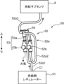
- [Relationship between the atmospheric release position and the supply side regulator] 9 is a perspective view showing the layout of the pressurizing pipe 52 and the branch pipe 53 in the pressurizing device 50.
- the supply-side regulator 51 is disposed below the supply sub-tank 8.
- the first throttle valve 52b of the pressurizing pipe 52 and the second throttle valve 53b of the branch pipe 53 are disposed between the supply-side regulator 51 and the supply sub-tank 8 in a side-by-side relationship.
- a joint 54 is disposed above the second throttle valve 53b. The joint 54 functions as a branch point between the pressurizing pipe 52 and the branch pipe 53.
- the first connecting pipe section 52a of the pressurizing pipe 52 is arranged to extend from the supply side regulator 51 through the first throttle valve 52b and the joint 54 to the supply sub-tank 8. That is, the first connecting pipe section 52a has an upstream tube 52a1 that connects the supply side regulator 51 to the upper end (inlet) of the first throttle valve 52b, a relay tube 52a2 that connects the lower end (outlet) of the first throttle valve 52b to the joint 54, and a downstream tube 52a3 that connects the joint 54 to the supply sub-tank 8.
- Each of the tubes 52a1, 52a2, 52a3 is arranged to extend vertically while being bent or changed in direction as appropriate.
- the second connecting pipe section 53a of the branch pipe 53 is disposed so as to extend downward from the joint 54.
- the lower end of this second connecting pipe section 53a is connected to the upper end (inlet) of the second throttle valve 53b.
- the lower end (outlet) of the second throttle valve 53b is open to the atmosphere above the supply side regulator 51.
- the end of the branch pipe 53 i.e., the atmosphere opening port, is located higher than the connection C1 between the pressurizing pipe 52 and the supply side regulator 51.
- the pressurizing device 50 includes a supply-side regulator 51 that reduces the pressure of the air sent from the pressure source 100, a pressurizing pipe 52 that connects the supply-side regulator 51 and the supply subtank 8, and a branch pipe 53 that branches off from the middle of the pressurizing pipe 52 and is open to the atmosphere at its end.
- This configuration has the advantage of improving the accuracy of pressure adjustment in the supply subtank 8.
- the pressure pipe 52 is interposed between the supply side regulator 51 and the supply subtank 8, and the end of the branch pipe 53 that branches off from the middle of the pressure pipe 52 is open to the atmosphere, so that the pressure supplied from the outlet of the pressure pipe 52 to the supply subtank 8 is lower than the outlet pressure of the supply side regulator 51 by a predetermined ratio.
- the pressure reduction rate is determined based on the fluid resistance of the pressure pipe 52 and the branch pipe 53, so that the desired positive pressure can be supplied to the supply subtank 8 by adjusting each fluid resistance.
- the supply side pressure change rate ⁇ Pa which is the ratio of the change in the pressure of the supply subtank 8 (supply subtank pressure PAin) to the change in the outlet pressure of the supply side regulator (supply side regulated pressure PAout), becomes a value significantly smaller than 1. Therefore, the pressure of the supply subtank 8 can be adjusted in a finer unit than the pressure adjustment unit by the supply side regulator 51 itself, and the pressure of the supply subtank 8 can be accurately kept close to the target value.
- negative pressure is supplied from the pressure reducing device 60 to the collection subtank 9 via air (gas) so that the inside of the collection subtank 9 becomes a negative pressure lower than atmospheric pressure.
- the pressure reducing device 60 includes a collection side regulator 61 that reduces the pressure of the air sent from the pressure source 100, a vacuum ejector 63 that generates negative pressure using the flow of air flowing in from the collection side regulator 61, and a connecting pipe 64 that connects the negative pressure port 63c of the vacuum ejector 63 to the collection subtank 9. This configuration has the advantage of improving the accuracy of pressure adjustment in the collection subtank 9.
- the absolute value of the pressure at the negative pressure port 63c of the vacuum ejector 63 becomes sufficiently smaller than the inlet pressure of the vacuum ejector 63.
- a negative pressure with an absolute value sufficiently smaller than the outlet pressure of the recovery side regulator 61 is applied to the recovery subtank 9.
- the absolute value of the recovery side pressure change rate ⁇ Pb which is the ratio of the change in the pressure of the recovery subtank 9 (recovery subtank pressure PBin) to the change in the outlet pressure of the recovery side regulator 61 (recovery side regulated pressure PBout) becomes sufficiently smaller than 1. This makes it possible to adjust the pressure of the recovery subtank 9 in finer units than the pressure adjustment unit by the recovery side regulator 61 itself, and to precisely keep the pressure of the recovery subtank 9 close to the target value.
- positive pressure is supplied from the pressure device 50 to the supply subtank 8, and negative pressure is supplied from the pressure reducing device 60 to the recovery subtank 9.
- This configuration makes it easy to increase the pressure difference between the supply subtank 8 and the recovery subtank 9, and can increase the upper limit of the amount of ink that can be circulated between the two tanks 8, 9. This makes it possible to increase the upper limit of the amount of ink that can be ejected from the ink head 4 per unit time, improving printing performance.
- a first throttle valve 52b is provided in the pressurizing pipe 52
- a second throttle valve 53b is provided in the branch pipe 53.
- the first throttle valve 52b can function as a resistance component that substantially controls the fluid resistance of the pressurizing pipe 52
- the second throttle valve 53b can function as a resistance valve that substantially controls the fluid resistance of the branch pipe 53.
- the fluid resistances of the pressurizing pipe 52 and the branch pipe 53 can be easily changed, and the supply side pressure change rate ⁇ Pa described above can be adjusted accordingly. This allows the unit of pressure adjustment of the supply subtank 8 to be reduced to a desired level, and the pressure of the supply subtank 8 can be adjusted with precision.
- the resistance ratio obtained by dividing the second resistance R2 by the sum of the first resistance R1 and the second resistance R2 (R1+R2) is set in the range of 1/5 to 1/50.
- the pressure of the supply subtank 8 (supply subtank pressure PAin) can be reduced to 1/5 to 1/50 of the outlet pressure of the supply side regulator 51 (supply side regulated pressure PAout), thereby improving the pressure adjustment accuracy of the supply subtank 8.
- the branch pipe 53 branches downward from the pressure pipe 52.
- the end of the branch pipe 53 which is the air opening, is located at a higher position than the connection C1 ( Figure 9) between the pressure pipe 52 and the supply-side regulator 51.
- the outlet pressure of the supply side regulator 51 is adjusted based on the pressure of the supply sub-tank 8 detected by the first pressure sensor SN1
- the outlet pressure of the recovery side regulator 61 is adjusted based on the pressure of the recovery sub-tank 9 detected by the second pressure sensor SN2.
- the pressure source 100 consisting of an air compressor provided outside the inkjet printer 1 is used as the source of compressed air used in the pressure device 50 and the pressure reduction device 60, but the source of compressed air is not limited to this.
- an air pressure pump that pressurizes and delivers air may be built into the inkjet printer 1 as the source of compressed air.
- positive pressure is supplied from the pressurizing device 50 to the supply sub-tank 8 via air
- negative pressure is supplied from the decompression device 60 to the recovery sub-tank 9 via air
- the medium for transmitting pressure to both tanks 8, 9 need only be gas and is not limited to air.
- pressure may be supplied to both tanks 8, 9 via a gas such as nitrogen gas.
- throttle valves 52b, 53b are provided in the pressurizing pipe 52 and the branch pipe 53 of the pressurizing device 50, respectively, but orifices may be provided instead of the throttle valves 52b, 53b.
- proportional valves whose opening can be electrically controlled may be provided instead of the throttle valves 52b, 53b.
- the parts that function as the main resistance components in the pressurizing pipe 52 and the branch pipe 53 i.e., the resistance parts, may have a larger fluid resistance than the parts other than the resistance parts (base pipe parts 52a, 53a), and the type of resistance parts may be changed as appropriate.
- the ink heads 4 are not limited to being arranged in two rows on the carriage 3.
- the ink heads 4 may be arranged in a single row, or in three or more rows.
- the inkjet printer 1 is not limited to being configured to be capable of ejecting ink of multiple colors onto the workpiece W, and may be configured to eject ink of a single color.
- the inkjet printer 1 may not have the pre-treatment liquid head 5 that ejects the pre-treatment liquid, the post-treatment liquid head 6 that ejects the post-treatment liquid, or any of the components associated with these.
- Inkjet printer (recording device) 4. Ink head (liquid ejection head) 7 Liquid supply device 8 Supply sub-tank (supply tank) 9. Recovery subtank (recovery tank) 50 Pressurizing device 51 Supply side regulator 52 Pressurizing pipe 52a First base pipe section 52b First throttle valve (first resistance section) 53 Branch pipe 53a Second connecting pipe section 53b Second throttle valve (second resistance section) 60 Pressure reducing device 61 Recovery side regulator 63 Vacuum ejector 64 Connection pipe 90 Controller C1 Connection portion SN1 First pressure sensor SN2 Second pressure sensor
Landscapes
- Ink Jet (AREA)
Abstract
Priority Applications (1)
| Application Number | Priority Date | Filing Date | Title |
|---|---|---|---|
| JP2025526082A JPWO2024253023A1 (fr) | 2023-06-06 | 2024-05-30 |
Applications Claiming Priority (2)
| Application Number | Priority Date | Filing Date | Title |
|---|---|---|---|
| JP2023-092876 | 2023-06-06 | ||
| JP2023092876 | 2023-06-06 |
Publications (1)
| Publication Number | Publication Date |
|---|---|
| WO2024253023A1 true WO2024253023A1 (fr) | 2024-12-12 |
Family
ID=93795962
Family Applications (1)
| Application Number | Title | Priority Date | Filing Date |
|---|---|---|---|
| PCT/JP2024/019960 Ceased WO2024253023A1 (fr) | 2023-06-06 | 2024-05-30 | Dispositif d'alimentation en liquide et dispositif d'impression équipé de celui-ci |
Country Status (2)
| Country | Link |
|---|---|
| JP (1) | JPWO2024253023A1 (fr) |
| WO (1) | WO2024253023A1 (fr) |
Citations (5)
| Publication number | Priority date | Publication date | Assignee | Title |
|---|---|---|---|---|
| JP2006159500A (ja) * | 2004-12-03 | 2006-06-22 | Sharp Corp | インクジェット記録装置 |
| JP2013180527A (ja) * | 2012-03-02 | 2013-09-12 | Seiren Co Ltd | インク置換方法 |
| JP2013223867A (ja) * | 2013-06-12 | 2013-10-31 | Seiko Epson Corp | 吸引装置およびこれを備えた液滴吐出装置 |
| WO2017167611A1 (fr) * | 2016-04-01 | 2017-10-05 | Till Gmbh | Dispositif et procédé d'alimentation en encre pour impression numérique |
| JP2019010789A (ja) * | 2017-06-30 | 2019-01-24 | セイコーエプソン株式会社 | 液体吐出装置および液体吐出装置の制御方法 |
-
2024
- 2024-05-30 WO PCT/JP2024/019960 patent/WO2024253023A1/fr not_active Ceased
- 2024-05-30 JP JP2025526082A patent/JPWO2024253023A1/ja active Pending
Patent Citations (5)
| Publication number | Priority date | Publication date | Assignee | Title |
|---|---|---|---|---|
| JP2006159500A (ja) * | 2004-12-03 | 2006-06-22 | Sharp Corp | インクジェット記録装置 |
| JP2013180527A (ja) * | 2012-03-02 | 2013-09-12 | Seiren Co Ltd | インク置換方法 |
| JP2013223867A (ja) * | 2013-06-12 | 2013-10-31 | Seiko Epson Corp | 吸引装置およびこれを備えた液滴吐出装置 |
| WO2017167611A1 (fr) * | 2016-04-01 | 2017-10-05 | Till Gmbh | Dispositif et procédé d'alimentation en encre pour impression numérique |
| JP2019010789A (ja) * | 2017-06-30 | 2019-01-24 | セイコーエプソン株式会社 | 液体吐出装置および液体吐出装置の制御方法 |
Also Published As
| Publication number | Publication date |
|---|---|
| JPWO2024253023A1 (fr) | 2024-12-12 |
Similar Documents
| Publication | Publication Date | Title |
|---|---|---|
| KR100202725B1 (ko) | 인쇄 장치 | |
| EP1938994B1 (fr) | Dégazage d'encre pour la circulation de système d'alimentation en encre dans des imprimantes à jet d'encre | |
| JP5466293B2 (ja) | 固定式の印刷ヘッド及び可動式の真空プラテンを備える印刷システム | |
| US8657394B2 (en) | Image forming apparatus | |
| KR101390403B1 (ko) | 잉크젯 프린터의 제어장치 및 제어방법 | |
| JP7488398B2 (ja) | インクジェット記録装置 | |
| US10350921B2 (en) | Carriage assembly for a printer having independent reservoirs | |
| JP2022183384A (ja) | インクジェット記録装置 | |
| US7841680B2 (en) | Ink jet printing apparatus and ink jet printing method | |
| CA2370674C (fr) | Appareil d'impression a l'encre sans ecoulement et methode d'utilisation de ce dernier | |
| US20070176984A1 (en) | Liquid ejecting apparatus | |
| US8480199B2 (en) | Method of printing with anti-curl solution | |
| JP7700398B2 (ja) | 液体供給装置およびこれを備えたインクジェット記録装置、液体供給方法 | |
| JPH08276573A (ja) | インクジェットプリント装置 | |
| JP5413168B2 (ja) | 画像形成装置 | |
| EP4566823A1 (fr) | Dispositif de mesure de pression et dispositif d'enregistrement en étant doté | |
| JP2025014315A (ja) | 液体吐出装置 | |
| US20050151769A1 (en) | Method and system for compensating for systematic variability in fluid ejection systems to improve fluid ejection quality | |
| US11813869B2 (en) | Liquid droplet ejecting apparatus | |
| JP7758903B1 (ja) | 記録装置及び記録方法 | |
| US20250289230A1 (en) | Printing unit and recording apparatus | |
| JP3943557B2 (ja) | 膜塗布装置および膜塗布方法 | |
| WO2024242093A1 (fr) | Réservoir de stockage de liquide, dispositif de circulation de liquide, dispositif d'enregistrement équipé de celui-ci, et groupe de réservoirs de stockage de liquide | |
| US20240308204A1 (en) | Recording apparatus | |
| WO2024202241A1 (fr) | Dispositif de circulation d'encre, dispositif d'impression à jet d'encre équipé de celui-ci, et pompe à encre |
Legal Events
| Date | Code | Title | Description |
|---|---|---|---|
| 121 | Ep: the epo has been informed by wipo that ep was designated in this application |
Ref document number: 24819253 Country of ref document: EP Kind code of ref document: A1 |
|
| ENP | Entry into the national phase |
Ref document number: 2025526082 Country of ref document: JP Kind code of ref document: A |
|
| WWE | Wipo information: entry into national phase |
Ref document number: 2025526082 Country of ref document: JP |
|
| NENP | Non-entry into the national phase |
Ref country code: DE |
|
| 122 | Ep: pct application non-entry in european phase |
Ref document number: 24819253 Country of ref document: EP Kind code of ref document: A1 |