WO2024253056A1 - Vehicular glass plate, and method for manufacturing vehicular glass plate - Google Patents
Vehicular glass plate, and method for manufacturing vehicular glass plate Download PDFInfo
- Publication number
- WO2024253056A1 WO2024253056A1 PCT/JP2024/020168 JP2024020168W WO2024253056A1 WO 2024253056 A1 WO2024253056 A1 WO 2024253056A1 JP 2024020168 W JP2024020168 W JP 2024020168W WO 2024253056 A1 WO2024253056 A1 WO 2024253056A1
- Authority
- WO
- WIPO (PCT)
- Prior art keywords
- optical element
- glass plate
- groove
- vehicle
- adhesive member
- Prior art date
- Legal status (The legal status is an assumption and is not a legal conclusion. Google has not performed a legal analysis and makes no representation as to the accuracy of the status listed.)
- Ceased
Links
Images









Classifications
-
- B—PERFORMING OPERATIONS; TRANSPORTING
- B32—LAYERED PRODUCTS
- B32B—LAYERED PRODUCTS, i.e. PRODUCTS BUILT-UP OF STRATA OF FLAT OR NON-FLAT, e.g. CELLULAR OR HONEYCOMB, FORM
- B32B17/00—Layered products essentially comprising sheet glass, or glass, slag, or like fibres
-
- B—PERFORMING OPERATIONS; TRANSPORTING
- B60—VEHICLES IN GENERAL
- B60J—WINDOWS, WINDSCREENS, NON-FIXED ROOFS, DOORS, OR SIMILAR DEVICES FOR VEHICLES; REMOVABLE EXTERNAL PROTECTIVE COVERINGS SPECIALLY ADAPTED FOR VEHICLES
- B60J1/00—Windows; Windscreens; Accessories therefor
Definitions
- This disclosure relates to a glass plate for a vehicle and a method for manufacturing the glass plate for a vehicle.
- LEDs light-emitting diodes
- Patent Documents 1 and 2 listed below disclose technology for attaching optical elements to glass panels on the inside of a vehicle using an adhesive material.
- Patent documents 1 and 2 disclose techniques for attaching an optical element to a glass plate using an adhesive member.
- Glass plates for vehicles may be curved. For this reason, if an optical element is attached to a curved glass plate using an adhesive, the thickness of the adhesive between the glass plate and the optical element will be uneven, making it difficult to control the thickness of the adhesive. This creates a problem in that the optical element cannot be properly attached to the curved glass plate.
- an elastic spacer is used to adhere a prism (optical element) to curved glass.
- the adhesive material is filled to a height (thickness) or less than the spacer before the prism is pressed against it, so air bubbles or an air layer may remain at the interface between the glass plate and the prism, significantly reducing the efficiency of introducing light into the glass plate.
- reflection at the interface between the prism and the spacer may reduce the efficiency of introducing light into the glass plate.
- the spacer is elastic, there is a risk that the thickness of the adhesive material may deviate from the desired value when the prism is pressed against it.
- the object of the present disclosure is to provide a glass plate for a vehicle that allows optical elements to be appropriately attached to a curved glass plate, and a method for manufacturing such a glass plate for a vehicle.
- the vehicle glass plate and the method for manufacturing the vehicle glass plate according to one aspect of the present disclosure may have the following configuration.
- a curved glass plate an optical element bonded to the surface of the glass plate using an adhesive member; a groove is formed in at least a part of a main surface of the optical element facing the glass plate, and at least a part of the groove is connected to an outside at a side surface of the optical element; The optical element is bonded to the glass plate in a state where the adhesive member is filled in the groove.
- Vehicle glass panels
- the optical element has a rectangular shape when viewed in a plane, the hole is formed on one side surface of the optical element that faces each other in the short side direction, and a light source is provided on the other side surface or in the vicinity thereof.
- optical element has a rectangular shape when viewed in a plane, and the groove portion is provided with a beam portion extending in a direction intersecting a longitudinal direction of the optical element.
- the glass plate for a vehicle according to any one of [1] to [9].
- the glass plate is a laminated glass including a first glass plate, a second glass plate, and an intermediate adhesive layer disposed between the first glass plate and the second glass plate.
- the glass plate for a vehicle according to any one of [1] to [12].
- the optical element is made of an elastic material
- the optical element In the step of adhering the optical element to the glass plate, the optical element is pressed against the glass plate, and the adhesive member is cured after the optical element is elastically deformed.
- This disclosure provides a glass plate for vehicles that allows optical elements to be appropriately attached to a curved glass plate, and a method for manufacturing the glass plate for vehicles.
- FIG. 1 is a plan view showing an example of a configuration of a glass plate for a vehicle according to an embodiment.
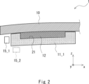
- 2 is a cross-sectional view of the vehicle glass plate shown in FIG. 1 along line II-II.
- FIG. 2 is a plan view showing a configuration example of an optical element.
- FIG. 2 is a cross-sectional view showing a configuration example of an optical element.
- FIG. 2 is a cross-sectional view showing a configuration example of an optical element.
- FIG. 2 is a cross-sectional view showing a configuration example of an optical element.
- FIG. 2 is a cross-sectional view showing a configuration example of an optical element.
- FIG. 2 is a cross-sectional view showing a configuration example of an optical element.
- FIG. 2 is a cross-sectional view showing a configuration example of an optical element.
- FIG. 2 is a cross-sectional view showing a configuration example of an optical element.
- FIG. 2 is a cross-sectional view showing a
- FIG. 1 is a cross-sectional view showing an example of a configuration of a glass plate for a vehicle according to an embodiment.
- FIG. 1 is a cross-sectional view showing an example of a configuration of a glass plate for a vehicle according to an embodiment.
- FIG. 1 is a cross-sectional view showing an example of a configuration of a glass plate for a vehicle according to an embodiment.
- FIG. 2 is a plan view showing a configuration example of an optical element.
- FIG. 2 is a plan view showing a configuration example of an optical element.
- FIG. 2 is a plan view showing a configuration example of an optical element.
- FIG. 2 is a plan view showing a configuration example of an optical element.
- FIG. 2 is a plan view showing a configuration example of an optical element.
- FIG. 2 is a plan view showing a configuration example of an optical element.
- FIG. 2 is a plan view showing a configuration example of an optical element.
- FIG. 2 is a plan view showing a configuration
- FIG. 2 is a plan view showing a configuration example of an optical element.
- FIG. 2 is a plan view showing a configuration example of an optical element.
- FIG. 2 is a plan view showing a configuration example of an optical element.
- FIG. 2 is a cross-sectional view illustrating a method for manufacturing a glass plate for a vehicle according to an embodiment.
- FIG. 1 is a plan view showing a configuration example of a vehicle glass plate according to an embodiment.
- FIG. 2 is a cross-sectional view of the vehicle glass plate shown in FIG. 1 along the cutting line II-II.
- the vehicle glass plate 1 according to the embodiment includes a glass plate 10 and optical elements 11_1 and 11_2.
- the optical element 11_1 is bonded to the surface of the glass plate 10 using an adhesive member 12.
- the optical element 11_2 is bonded to the surface of the glass plate 10 using an adhesive member 12.
- the optical elements 11_1 and 11_2 are also collectively referred to as the optical element 11. The same applies to other components.
- the vehicle glass plate 1 can be used, for example, as a vehicle window.
- vehicle windows include roof glass, windshields, side windows, rear windows, and the like.
- the vehicle glass plate 1 can be configured to introduce irradiation light from an end of the vehicle glass plate 1 into the interior of the vehicle glass plate using a light source such as an LED, and to scatter the light on the surface or inside of the vehicle glass plate and extract the light to the outside.
- a light source such as an LED
- the ceiling part inside the vehicle can be illuminated in a predetermined color, improving the design inside the vehicle.
- Information notification includes, for example, a danger alert and a notification of the vehicle status, but is not limited to these.
- the light extracted to the outside of the vehicle glass plate 1 can be used for various purposes depending on the mounting position of the vehicle glass plate 1 on the vehicle.
- the glass plate 10 has a rectangular shape with the y-axis direction as the longitudinal direction. Also, as shown in FIG. 2, the glass plate 10 has a curved shape. Specifically, the glass plate 10 may have a single curved shape curved in one direction, or a three-dimensional shape curved in two or more directions. The three-dimensional shape may be, for example, a compound curved shape curved in two perpendicular directions. Note that in the drawings other than FIG. 2, the glass plate 10 is shown in an uncurved state to simplify the drawings, but the glass plate 10 used in this embodiment has a curved shape.
- the glass plate 10 used in this embodiment may be a single glass plate or may be laminated glass.
- the glass plate 10 includes a first glass plate, a second glass plate, and an intermediate adhesive layer disposed between the first glass plate and the second glass plate.
- the first and second glass plates can be made of, for example, transparent inorganic glass.
- first and second glass plates for example, soda lime glass, aluminosilicate glass, borosilicate glass, alkali-free glass, quartz glass, etc. may be used.
- the first and second glass plates are manufactured using, for example, the float method, the fusion method, etc., but are not limited to these manufacturing methods.
- the thickness of the glass plate is preferably 1.5 mm to 10 mm.
- the thickness of the glass plate may be, for example, 1.8 mm or more, 2.5 mm or more, or 2.8 mm or more.
- the thickness of the glass plate may be 6 mm or less, 4 mm or less, 3.1 mm or less, or 2.3 mm or less.
- the upper and lower limits of the above numerical ranges may be combined in any way, and may be, for example, 2.4 mm to 4 mm.
- the thickness of each of the first and second glass plates is, for example, 0.1 mm to 10 mm, and is preferably 0.3 mm or more, and more preferably 0.5 mm or more, from the viewpoint of resistance to flying stone impact.
- the thickness of each of the first and second glass plates is preferably 3 mm or less, more preferably 2.6 mm or less, and even more preferably 2.1 mm or less.
- the upper and lower limits of the above numerical ranges can be combined arbitrarily, and may be, for example, 0.3 mm to 3.0 mm, 1.1 mm to 2.6 mm, or 1.7 mm to 2.1 mm.
- the thicknesses of the first and second glass plates may be the same or different from each other.
- the thickness of the first glass plate arranged on the outside of the vehicle may be thicker than the thickness of the second glass plate arranged on the inside of the vehicle. In this way, when the thickness of the first glass plate arranged on the outside of the vehicle is thickened, the strength of the glass plate 10 against objects flying toward the vehicle window glass plate 1 is improved.
- the intermediate adhesive layer is disposed so as to be sandwiched between the first glass plate and the second glass plate.
- the thickness of the intermediate adhesive layer is not particularly limited, but is, for example, 0.3 mm to 3 mm.
- the thickness of the intermediate adhesive layer is preferably 2.40 mm or less, and more preferably 1.10 mm or less.
- the thickness of the intermediate adhesive layer is preferably 0.50 mm or more, and more preferably 0.70 mm or more.
- the intermediate adhesive layer is preferably made of a thermoplastic resin or a curable resin, with a thermoplastic resin being particularly preferred.
- the intermediate adhesive layer can be made of polyvinyl butyral (PVB) resin, ethylene vinyl acetate copolymer (EVA) resin, polyurethane resin, ionomer resin, cycloolefin polymer, etc.
- PVB resin polyvinyl butyral
- EVA resin ethylene vinyl acetate copolymer
- polyurethane resin polyurethane resin
- ionomer resin ionomer resin
- cycloolefin polymer cycloolefin polymer
- the optical elements 11_1 and 11_2 are bonded to the surface of the glass plate 10 using an adhesive member 12.
- two optical elements 11_1 and 11_2 extending in the y-axis direction are provided near the end of the glass plate 10 on the negative side in the x-axis direction and near the end on the positive side in the x-axis direction, respectively.
- a light source 15_1 is provided near the end of the optical element 11_1 on the negative side in the x-axis direction. This allows light from the light source 15_1 to be introduced to the end of the vehicle glass plate 1 on the negative side in the x-axis direction via the optical element 11_1.
- the light source may be placed at the position of light source 15_2, or two light sources may be provided at the positions of light source 15_1 and light source 15_2.
- the optical element 11 has, for example, a rectangular parallelepiped shape, a triangular prism shape, or a trapezoidal prism shape. In this embodiment, the optical element 11 has a rectangular parallelepiped shape as an example. Each surface constituting the optical element 11 may be curved, and the corners may be curved.
- the optical element 11 is made of glass or a resin material. For example, polycarbonate, acrylic resin, epoxy resin, silicone rubber, etc. may be used as the resin material. Since the resin material is an elastic body, when the optical element 11 is made of a resin material, the optical element 11 can be made of an elastic body.
- the optical element 11 may be curved in advance to match the curved shape of the surface of the glass plate 10.
- the optical element 11 when the optical element 11 is made of a material that is difficult to deform, the optical element 11 is curved in advance to match the curved shape of the surface of the glass plate 10. Since a glass plate with a thickness of 2 mm or more is difficult to deform at room temperature, the optical element 11 needs to be thermally bent in advance to be formed into a curved shape.
- the optical element 11 when the optical element 11 is constructed using a glass plate having a thickness of less than 2 mm, preferably 1.4 mm or less, and more preferably 1 mm or less, the optical element 11 can be elastically deformed to fit the curved shape of the surface of the glass plate 10 at room temperature. It is particularly preferable to subject such glass plates to a strengthening treatment such as chemical strengthening.
- the optical element 11 may be colored to the extent that the effect of the present disclosure is not impaired.
- the refractive index of the optical element 11 is close to the refractive index of the glass plate 10. For example, if the refractive index of the glass plate 10 is about 1.52, it is preferable that the refractive index of the optical element 11 is about 1.45 or more and 1.60 or less.
- a groove 21 is formed in at least a part of the main surface of the optical element 11 facing the glass plate (the main surface on the positive side in the z-axis direction), and at least a part of the groove 21 is connected to the outside on the side of the optical element.
- the optical element 11 is adhered to the glass plate 10 with the adhesive member 12 filled in the groove 21. Therefore, the optical element 11 also functions as a spacer that sets the adhesive member 12 to a predetermined thickness. This eliminates the need to prepare a separate spacer, and also prevents an increase in the interface between the members.
- FIG. 3 is a plan view showing an example of the configuration of an optical element.
- the optical element 11 has a groove portion 21 on the main surface on the positive side of the z-axis direction of the optical element 11.
- the depth of the groove portion 21 may be adjusted, for example, in the range of 30 ⁇ m to 3,000 ⁇ m depending on the thickness of the optical element 11 and the fluidity of the adhesive member 12 before hardening.
- the groove portion 21 is shallow in order to prevent the adhesive member 12 from excessively flowing out of the groove portion 21.
- the area of the groove portion 21 when viewed in plan from the z-axis direction is preferably 30% to 95% of the area of the optical element 11, and may be, for example, 50% to 90% or 70% to 80%.
- the length (width) of the optical element 11 in the x-axis direction is 10 mm or more and 50 mm or less
- the length of the optical element 11 in the y-axis direction is 50 mm or more and 900 mm or less
- the length (thickness) of the optical element 11 in the z-axis direction is 0.5 mm or more and 10 mm or less.
- the size of the optical element 11 may be other than these.
- the width of the optical element 11 may be 15 mm or more, or 20 mm or more.
- the width of the optical element 11 may be 40 mm or less, or 30 mm or less.
- the length of the optical element 11 may be 100 mm or more, 150 mm or more, or 300 mm or more.
- the length of the optical element 11 may be 700 mm or less, or 500 mm or less.
- the thickness of the optical element 11 is preferably 0.7 mm or more, and more preferably 1 mm or more. This thickness makes it easier to form a groove sufficient for adhesion, and durability is less likely to decrease.
- the thickness of the optical element 11 is preferably 5 mm or less, more preferably 3 mm or less, and even more preferably 2.1 mm or less. This thickness prevents the light guide efficiency from decreasing too much, and makes it easier to follow curved shapes.
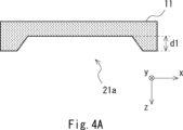
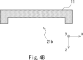
- FIG. 4A to 4C are cross-sectional views showing examples of the configuration of an optical element, and are cross-sectional views of the optical element 11 shown in FIG. 3 along the cutting line IV-IV, in other words, cross-sectional views of a portion of the optical element 11 including the groove portion 21.
- the cross-sectional shape of the groove portion 21a may be trapezoidal.
- the cross-sectional shape of the groove portion 21b may be rectangular.
- the cross-sectional shape of the groove portion 21c may be a shape in which the corners away from the glass plate 10 (i.e., at the position on the negative side in the z-axis direction) are curved.
- the cross-sectional shape of the groove portion 21 is a trapezoid as shown in FIG. 4A or a shape in which the corners are curved as shown in FIG. 4C, it is easy to fill the corners of the groove portion 21 with the adhesive member 12 without gaps. Therefore, it is possible to reduce the occurrence of cavities between the optical element 11 and the adhesive member 12.
- the groove 21 of the optical element 11 is connected to the outside at a side of the optical element 11 other than the side on which the light source 15 is attached.
- the light source 15 is attached along the side of the optical element 11 on the negative side in the x-axis direction.
- the groove 21 of the optical element 11 is connected to the outside via holes 22, 23, and 24 provided in the side of the optical element 11. Connected to the outside means that the groove 21 is spatially continuous with the external space via the holes 22, 23, and 24.
- the adhesive member 12 is filled in the groove 21, the adhesive member 12 is also filled in at least a portion of the holes 22, 23, and 24.
- the adhesive member 12 can be made of a transparent adhesive, specifically, an optically transparent adhesive (OCR: Optical Clear Resin).
- OCR optical Clear Resin
- the optically transparent adhesive is a curing adhesive, and has fluidity before curing.
- an acrylate-based, silicone-based, urethane-based, urethane acrylate-based, epoxy-based, epoxy acrylate-based, acrylamide-based, or methacrylamide-based resin composition can be used for the adhesive member 12.
- the adhesive member 12 is an adhesive member that transmits at least visible light, and in this embodiment, an ultraviolet-curing resin may be used.
- a thermosetting resin or a reaction-curing resin may be used as the adhesive member 12.
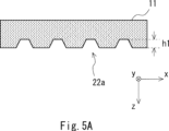
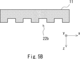
- 5A to 5C are cross-sectional views showing examples of the configuration of an optical element, and are cross-sectional views of the optical element 11 at the cutting line V-V shown in FIG. 3, in other words, cross-sectional views of a portion including the hole 22 of the optical element 11.
- the cross-sectional shape of the hole 22a may be trapezoidal.
- the cross-sectional shape of the hole 22b may be rectangular.
- the cross-sectional shape of the hole 22c may be semicircular.
- the height of the hole 22 provided on the side surface of the optical element 11 is approximately the same as the depth of the groove 21 of the optical element 11.
- the height h1 of the hole 22a shown in FIG. 5A and the depth d1 of the groove 21a shown in FIG. 4A are approximately the same. Also, in this embodiment, the height h1 of the hole 22a may be lower than the depth d1 of the groove 21a shown in FIG. 4A.
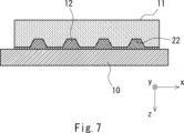
- FIGS. 6 to 8 are cross-sectional views showing an example of the configuration of a glass plate for a vehicle according to this embodiment, and are cross-sectional views for explaining the state in which an optical element 11 is adhered to the surface of a glass plate 10 using an adhesive member 12.
- FIG. 6 corresponds to the cross-sectional view of the optical element 11 shown in FIG. 3 taken along the section line IV-IV
- FIG. 7 corresponds to the cross-sectional view of the optical element 11 shown in FIG. 3 taken along the section line V-V
- FIG. 8 corresponds to the cross-sectional view of the optical element 11 shown in FIG. 3 taken along the section line VIII-VIII.
- the adhesive member 12 may be thinly provided between the optical element 11 and the glass plate 10 at each of the locations on the positive side in the x-axis direction and the negative side in the x-axis direction of the optical element 11.
- the adhesive member 12 may be thinly provided between the optical element 11 and the glass plate 10 at the location where the groove 21 of the optical element 11 is not provided.
- the thickness of the adhesive member 12 between the optical element 11 and the glass plate 10 at this location may be sufficiently smaller than the thickness at the location where the groove 21 is provided, and may be substantially close to zero. In this embodiment, the adhesive member 12 is less likely to protrude to the outside at this location during manufacturing.
- the optical element 11 is bonded to the glass plate 10 in a state where the adhesive member 12 is filled in the hole 22 at a location corresponding to the cutting line V-V of the optical element 11 shown in FIG. 3.
- the optical element 11 is bonded to the glass plate 10 in a state where the adhesive member 12 filled in the groove 21 reaches the hole 22.
- the adhesive member 12 may be thinly provided between the optical element 11 and the glass plate 10, in other words, between the optical element 11 and the glass plate 10 at a location where the hole 22 of the optical element 11 is not provided.
- the optical element 11 is adhered to the glass plate 10 using an adhesive member 12.
- the adhesive member 12 may be thinly provided between the optical element 11 and the glass plate 10.
- FIG. 6 to 8 show an example of a configuration in which a thin adhesive member 12 is provided between the optical element 11 and the glass plate 10 in areas other than where the grooves 21 and holes 22 are provided.
- the adhesive member 12 may not be provided between the optical element 11 and the glass plate 10 in areas other than where the grooves 21 and holes 22 are provided.
- the space between the optical element 11 and the glass plate 10 may be hollow, or a member other than the adhesive member 12 (e.g., a different adhesive member) may be provided.
- the optical element 11 and the glass plate 10 may also be in direct contact with each other.
- the groove 21 is formed in at least a part of the main surface of the optical element 11 facing the glass plate 10, and at least a part of the groove 21 is configured to be connected to the outside on the side surface of the optical element 11.
- the optical element 11 is bonded to the glass plate 10 with the adhesive member 12 filled in the groove 21 of the optical element 11.
- the adhesive member 12 is filled in the groove 21, and excess adhesive member 12 leaks out from the holes 22, 23, and 24 to the outside, so that the thickness of the adhesive member 12 between the glass plate 10 and the optical element 11 can be made uniform. Therefore, even if the glass plate 10 is curved, the optical element 11 can be appropriately attached to the curved glass plate 10. In addition, the individual difference (variation) in the thickness of the adhesive member 12 between the glass plate 10 and the optical element 11 can also be reduced.
- holes 22 and 23 may be formed on side surfaces facing each other in the longitudinal direction of the optical element 11a when the optical element 11a is viewed in a plan view.
- hole 22 may be formed on the side surface of the optical element 11a on the positive side in the y-axis direction
- hole 23 may be formed on the side surface of the optical element 11a on the negative side in the y-axis direction.
- the optical element 11a shown in FIG. 9 differs from the optical element 11 shown in FIG. 3 in that hole 24 is not formed on the side surface on the positive side in the x-axis direction.
- a hole 24 may be formed on one of the side surfaces that face each other in the short direction of the optical element 11b.
- the hole 24 may be formed on the side surface on the positive side of the x-axis direction of the optical element 11b.
- a light source is provided on the other side surface that faces each other in the short direction of the optical element 11b.
- the optical element 11b shown in FIG. 10 differs from the optical element 11 shown in FIG. 3 in that holes 22, 23 are not formed on the side surface on the positive side of the y-axis direction and the side surface on the negative side of the y-axis direction.
- the groove portion 21 may be provided with beam portions 25_1 to 25_3 extending in a direction intersecting the longitudinal direction of the optical element 11c.
- the beam portions 25_1 to 25_3 extending in the x-axis direction may be formed inside the groove portion 21.
- each of the groove portions 21_1 to 21_4 may be configured to be connected to the outside via at least one of the holes 22, 23, and 24.
- the position of the light source 15 is separated from the position of the beam portion 25. This can reduce scattering of light from the light source 15 by the beam portion 25.
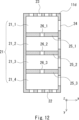
- the beam portions 25_1 to 25_3 may be provided with communication openings 26_1 to 26_3, and the groove portions 21_1 to 21_4 divided by the beam portions 25_1 to 25_3 may be connected to each other via the communication openings 26_1 to 26_3.
- the adhesive material 12 filled in each of the groove portions 21_1 to 21_4 can be made uniform.
- FIG. 12 shows a configuration example in which the communication openings 26_1 to 26_3 are provided in the center of each of the beam portions 25_1 to 25_3, the positions at which the communication openings 26_1 to 26_3 are formed can be determined arbitrarily.
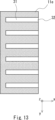
- a configuration may be used in which multiple grooves 31 extending in the x-axis direction are formed.
- a hole 32 is provided at the end of the groove 31 on the positive side in the x-axis direction.
- the groove 31 is connected to the outside on the side surface on the positive side in the x-axis direction of the optical element 11e, and the end of the groove 31 forms the hole 32.
- a configuration may be used in which a groove portion 33 extending in the y-axis direction is formed, as in optical element 11f shown in FIG. 14.
- a hole portion 34 is provided at the end of groove portion 33 on the positive side in the y-axis direction
- a hole portion 35 is provided at the end of groove portion 33 on the negative side in the y-axis direction.
- groove portion 33 is connected to the outside at the side surface of optical element 11f on the positive side in the y-axis direction
- groove portion 33 is connected to the outside at the side surface of optical element 11f on the negative side in the y-axis direction
- each end of groove portion 33 forms hole portions 34, 35.
- the configuration shown in FIG. 13 may be combined with the configuration shown in FIG. 14. That is, as in the optical element 11g shown in FIG. 15, a configuration may be used that includes a groove portion 33 extending in the y-axis direction and multiple groove portions 31 extending in the x-axis direction and connected to the groove portion 33.
- a hole portion 32 is provided at the end of the groove portion 31 on the positive side in the x-axis direction
- a hole portion 34 is provided at the end of the groove portion 33 on the positive side in the y-axis direction
- a hole portion 35 is provided at the end of the groove portion 33 on the negative side in the y-axis direction. Note that the position where the groove portion 33 is connected to the multiple groove portions 31 is not limited to the end of the multiple groove portions 31.
- any configuration may be used as long as a groove is formed in at least a part of the main surface of the optical element 11 facing the glass plate 10, and at least a part of the groove is connected to the outside on the side surface of the optical element 11.
- the grooves 31 and 33 may be arranged in a curved shape rather than a straight line.
- a through hole penetrating in the thickness direction may be further provided in the main surface of the optical element 11.
- excess adhesive material 12 can escape to the outside through both the hole portion 22 and the through hole.
- the through hole is preferably provided in a position on the main surface of the optical element 11 that does not affect (or has little effect on) the optical properties of the optical element 11.
- the through hole provided in the main surface of the optical element 11 may also be used to fix other members, such as a cover, to the vehicle glass plate.
- Figure 16 is a cross-sectional view for explaining an example of a method for manufacturing a vehicle glass plate according to the present embodiment, showing a portion of the vehicle glass plate.
- an optical element 11 having a groove 21 formed therein is prepared.
- the optical element described above is used for the optical element 11.
- an adhesive member 12 is applied to the curved glass plate 10 or the groove 21 of the optical element 11.
- the upper diagram of FIG. 16 illustrates a case where the adhesive member 12 has been applied to the groove 21 of the optical element 11.
- the adhesive member 12 may be applied continuously along the longitudinal direction of the groove 21.
- the adhesive member 12 may also be applied to multiple locations along the longitudinal direction of the groove 21 of the optical element 11.
- the adhesive member 12 When applying the adhesive member 12 to the glass plate 10, the adhesive member 12 is applied at a position such that the adhesive member 12 applied to the glass plate 10 fills the grooves 21 of the optical element 11 when the glass plate 10 and the optical element 11 are bonded together.
- the adhesive member 12 may be applied to both the glass plate 10 and the grooves 21 of the optical element 11.
- the optical element 11 is bonded to the glass plate 10. That is, as shown in the center diagram of FIG. 16, the optical element 11 is pressed against the glass plate 10 with the main surface of the glass plate 10 facing the surface of the optical element 11 on which the grooves 21 are formed (the surface on which the adhesive member 12 is applied). After that, the adhesive member 12 is cured to bond the optical element 11 to the curved glass plate 10.
- the adhesive member 12 is an ultraviolet curing resin, as shown in the lower diagram of FIG. 16, the adhesive member 12 is cured by irradiating ultraviolet rays UV from the surface of the optical element 11 opposite to the surface on which the adhesive member 12 is applied.
- the adhesive member 12 may be cured by irradiating ultraviolet rays through the glass plate 10, or the adhesive member 12 may be cured by both ultraviolet irradiation from the surface of the optical element 11 opposite to the surface on which the adhesive member 12 is applied and ultraviolet irradiation through the glass plate 10.
- the groove 21 of the optical element 11 is connected to the outside on the side surface of the optical element 11. Therefore, as shown in the center diagram of FIG. 16, in the process of adhering the optical element 11 to the glass plate 10, when the optical element 11 is pressed against the glass plate 10, a portion of the adhesive member 12 protrudes from the hole 24 provided on the side surface of the optical element 11. In this embodiment, after the adhesive member 12 protrudes from the side surface of the optical element 11, the adhesive member 12 is cured to adhere the optical element 11 to the glass plate 10. In this way, the optical element 11 can be adhered to the glass plate 10 with the adhesive member 12 permeating the entire groove 21 of the optical element 11, so that the occurrence of cavities between the optical element 11 and the adhesive member 12 can be reduced.
- the adhesive member 12 may be cured in a state where the adhesive member 12 protrudes from the side surface of the optical element 11, and the state of the adhesive member 12 in this protruding portion may be checked to determine the degree of adhesion between the glass plate 10 and the optical element 11. For example, when the adhesive member 12 is cured, the volume of the adhesive member 12 decreases. In this embodiment, this property may be utilized to cure the adhesive member 12 in a state where the adhesive member 12 protrudes from the side surface of the optical element 11 (see the portion indicated by reference numeral 41 in the central drawing of FIG.
- the degree of adhesion between the glass plate 10 and the optical element 11 may be determined by checking that the adhesive member 12 in this protruding portion has been reduced (see the portion indicated by reference numeral 42 in the lower drawing of FIG. 16). In this case, when the adhesive member 12 is cured and the volume of the adhesive member 12 is reduced, the adhesive member 12 present in the hole portion 24 is replenished in the groove portion 21 (see the portion indicated by reference numeral 42 in the lower drawing of FIG. 16). This reduces the risk of air getting into the groove 21 when the adhesive member 12 hardens.
- the optical element 11 may be configured using an elastic body. In this case, the optical element 11 is pressed against the glass plate 10, the optical element 11 is elastically deformed, and then the adhesive member 12 is hardened, thereby adhering the optical element 11 to the glass plate 10.
- the manufacturing method for vehicle glass plates according to the present embodiment described above allows optical elements to be properly attached to curved glass plates.
Landscapes
- Engineering & Computer Science (AREA)
- Mechanical Engineering (AREA)
- Joining Of Glass To Other Materials (AREA)
Abstract
Description
本開示は、車両用ガラス板、及び車両用ガラス板の製造方法に関する。 This disclosure relates to a glass plate for a vehicle and a method for manufacturing the glass plate for a vehicle.
近年、発光ダイオード(LED:Light Emitting Diode)等の光源を用いて、車両用ガラス板の端部から車両用ガラス板の内部に照射光を導入し、車両用ガラス板の表面又は内部で光を散乱させて光を外部に取り出す技術が開発されている。 In recent years, technology has been developed that uses light sources such as light-emitting diodes (LEDs) to introduce light into the interior of a vehicle glass plate from its edge, and then scatters the light on the surface or inside of the vehicle glass plate to extract the light to the outside.
下記に列挙した特許文献1、2には、接着部材を用いて車内側のガラス板に光学素子を取り付ける技術が開示されている。
車両用ガラス板に光を導入する際は、車両用ガラス板に光学素子を設け、光源から出射された光をこの光学素子を介して車両用ガラス板に導入する。特許文献1、2には、接着部材を用いてガラス板に光学素子を取り付ける技術が開示されている。
When introducing light into a vehicle glass plate, an optical element is provided on the vehicle glass plate, and light emitted from a light source is introduced into the vehicle glass plate via this optical element.
車両用ガラス板は湾曲している場合がある。このため、湾曲したガラス板に接着部材を用いて光学素子を取り付けた場合は、ガラス板と光学素子との間の接着部材の厚さが不均一になり、接着部材の厚さの制御が困難になる。このため、湾曲したガラス板に光学素子を適切に取り付けられないという問題がある。 Glass plates for vehicles may be curved. For this reason, if an optical element is attached to a curved glass plate using an adhesive, the thickness of the adhesive between the glass plate and the optical element will be uneven, making it difficult to control the thickness of the adhesive. This creates a problem in that the optical element cannot be properly attached to the curved glass plate.
特許文献2では、プリズム(光学素子)を曲面ガラスに接着するにあたって、弾力性を有するスペーサー用いている。この場合、接着部材をスペーサーの高さ(厚さ)以下に充填した上でプリズムを押し当てるため、ガラス板とプリズムとの界面に気泡や空気層が残存し、ガラス板への光の導入効率が著しく低下するおそれがある。また、プリズムとスペーサーとの界面での反射により、ガラス板への光の導入効率が低下するおそれがある。また、スペーサーが弾性体であるため、プリズムの押し当て時に接着部材の厚さが所望の値からずれるおそれがある。
In
上記課題に鑑み、本開示の目的は、湾曲したガラス板に光学素子を適切に取り付け可能な車両用ガラス板、及びこうした車両用ガラス板の製造方法を提供することである。 In view of the above problems, the object of the present disclosure is to provide a glass plate for a vehicle that allows optical elements to be appropriately attached to a curved glass plate, and a method for manufacturing such a glass plate for a vehicle.
本開示の一態様にかかる車両用ガラス板、及び車両用ガラス板の製造方法は、下記の構成を備えるとよい。 The vehicle glass plate and the method for manufacturing the vehicle glass plate according to one aspect of the present disclosure may have the following configuration.
[1]
湾曲したガラス板と、
前記ガラス板の表面に接着部材を用いて接着された光学素子と、を備え、
前記光学素子の前記ガラス板に面する主面の少なくとも一部には、溝部が形成されており、当該溝部の少なくとも一部は、前記光学素子の側面において外部と繋がっており、
前記光学素子は、前記溝部に前記接着部材が充填された状態で前記ガラス板に接着されている、
車両用ガラス板。
[1]
A curved glass plate,
an optical element bonded to the surface of the glass plate using an adhesive member;
a groove is formed in at least a part of a main surface of the optical element facing the glass plate, and at least a part of the groove is connected to an outside at a side surface of the optical element;
The optical element is bonded to the glass plate in a state where the adhesive member is filled in the groove.
Vehicle glass panels.
[2]
前記溝部の深さが、30μm以上3,000μm以下である、[1]に記載の車両用ガラス板。
[2]
The glass plate for a vehicle according to [1], wherein the depth of the groove portion is 30 μm or more and 3,000 μm or less.
[3]
平面視した際の前記溝部の面積は、前記光学素子の面積の30%以上95%以下である、[1]または[2]に記載の車両用ガラス板。
[3]
The glass plate for a vehicle according to [1] or [2], wherein an area of the groove portion in a plan view is 30% to 95% of an area of the optical element.
[4]
前記光学素子の前記溝部の少なくとも一部は、前記光学素子の側面のうち光源が設けられる側面以外の側面において外部と繋がっている、[1]乃至[3]のいずれか一項に記載の車両用ガラス板。
[4]
[4] The glass plate for a vehicle according to any one of [1] to [3], wherein at least a part of the groove portion of the optical element is connected to the outside at a side surface of the optical element other than a side surface on which a light source is provided.
[5]
前記光学素子の前記溝部は、前記光学素子の側面に設けられた孔部を介して外部と繋がっている、[1]乃至[4]のいずれか一項に記載の車両用ガラス板。
[5]
The glass plate for a vehicle according to any one of [1] to [4], wherein the groove portion of the optical element is connected to the outside via a hole portion provided in a side surface of the optical element.
[6]
平面視した際、前記光学素子は、矩形状であり、前記孔部は、前記光学素子の長手方向において互いに対向する側面に形成されている、[5]に記載の車両用ガラス板。
[6]
The vehicle glass plate according to [5], wherein the optical element has a rectangular shape in a plan view, and the hole is formed on side surfaces of the optical element that face each other in a longitudinal direction.
[7]
平面視した際、前記光学素子は、矩形状であり、前記光学素子の短手方向において互いに対向する一方の側面には、前記孔部が形成されており、他方の側面またはその近傍には、光源が設けられる、[5]または[6]に記載の車両用ガラス板。
[7]
[5] or [6], wherein the optical element has a rectangular shape when viewed in a plane, the hole is formed on one side surface of the optical element that faces each other in the short side direction, and a light source is provided on the other side surface or in the vicinity thereof.
[8]
前記溝部の断面形状は、台形状である、[1]乃至[7]のいずれか一項に記載の車両用ガラス板。
[8]
The glass plate for a vehicle according to any one of [1] to [7], wherein a cross-sectional shape of the groove is a trapezoid.
[9]
前記溝部の断面形状は、前記ガラス板から離れた角部が湾曲した形状である、[1]乃至[7]のいずれか一項に記載の車両用ガラス板。
[9]
The glass plate for a vehicle according to any one of [1] to [7], wherein a cross-sectional shape of the groove portion is a shape in which a corner portion away from the glass plate is curved.
[10]
平面視した際、前記光学素子は、矩形状であり、前記溝部には前記光学素子の長手方向と交差する方向に伸びる梁部が設けられている、[1]乃至[9]のいずれか一項に記載の車両用ガラス板。
[10]
[1] to [9], wherein the optical element has a rectangular shape when viewed in a plane, and the groove portion is provided with a beam portion extending in a direction intersecting a longitudinal direction of the optical element. The glass plate for a vehicle according to any one of [1] to [9].
[11]
前記梁部には、連通口が設けられており、前記梁部によって分割された溝部同士が、前記連通口を介して繋がるように構成されている、[10]に記載の車両用ガラス板。
[11]
The vehicle glass plate according to [10], wherein a communication opening is provided in the beam portion, and the groove portions divided by the beam portion are configured to be connected to each other via the communication opening.
[12]
前記光学素子が、弾性体を用いて構成されている、[1]乃至[11]のいずれか一項に記載の車両用ガラス板。
[12]
The glass plate for a vehicle according to any one of [1] to [11], wherein the optical element is configured using an elastic body.
[13]
前記ガラス板が、第1ガラス板と、第2ガラス板と、前記第1ガラス板および前記第2ガラス板の間に配置された中間接着層と、を備える合わせガラスである、[1]乃至[12]のいずれか一項に記載の車両用ガラス板。
[13]
The glass plate is a laminated glass including a first glass plate, a second glass plate, and an intermediate adhesive layer disposed between the first glass plate and the second glass plate. The glass plate for a vehicle according to any one of [1] to [12].
[14]
溝部が形成された光学素子を準備する工程と、
湾曲したガラス板および前記光学素子の前記溝部の少なくとも一方に接着部材を塗布する工程と、
前記光学素子を前記ガラス板に接着する工程と、を備え、
前記光学素子の前記溝部の少なくとも一部は、前記光学素子の側面において外部と繋がっており、
前記光学素子を前記ガラス板に接着する工程において、前記光学素子を前記ガラス板に押し当てて、前記接着部材が前記光学素子の側面からはみ出た後に、前記接着部材を硬化させて、前記光学素子を前記ガラス板に接着する、
車両用ガラス板の製造方法。
[14]
preparing an optical element having a groove formed therein;
applying an adhesive material to at least one of the curved glass plate and the groove of the optical element;
and adhering the optical element to the glass plate.
At least a part of the groove of the optical element is connected to the outside at a side surface of the optical element,
In the step of adhering the optical element to the glass plate, the optical element is pressed against the glass plate, and after the adhesive member protrudes from a side surface of the optical element, the adhesive member is cured to adhere the optical element to the glass plate.
A method for manufacturing a glass sheet for a vehicle.
[15]
前記光学素子は、弾性体を用いて構成されており、
前記光学素子を前記ガラス板に接着する工程において、前記光学素子を前記ガラス板に押し当て、前記光学素子を弾性変形させた後に前記接着部材を硬化させる、
[14]に記載の車両用ガラス板の製造方法。
[15]
The optical element is made of an elastic material,
In the step of adhering the optical element to the glass plate, the optical element is pressed against the glass plate, and the adhesive member is cured after the optical element is elastically deformed.
The method for producing a glass plate for a vehicle according to [14].
本開示により、湾曲したガラス板に光学素子を適切に取り付け可能な車両用ガラス板、及び車両用ガラス板の製造方法を提供できる。 This disclosure provides a glass plate for vehicles that allows optical elements to be appropriately attached to a curved glass plate, and a method for manufacturing the glass plate for vehicles.
以下、図面を参照して実施の形態について説明する。
図1は、実施の形態にかかる車両用ガラス板の構成例を示す平面図である。図2は、図1に示す車両用ガラス板の切断線II-IIにおける断面図である。図1、図2に示すように、本実施の形態にかかる車両用ガラス板1は、ガラス板10と、光学素子11_1、11_2と、を備える。図2に示すように、光学素子11_1は、接着部材12を用いて、ガラス板10の表面に接着されている。光学素子11_2についても同様に、接着部材12を用いて、ガラス板10の表面に接着されている。なお、本実施の形態では、光学素子11_1、11_2を総称して光学素子11とも記載する。他の構成要素についても同様である。
Hereinafter, an embodiment will be described with reference to the drawings.
FIG. 1 is a plan view showing a configuration example of a vehicle glass plate according to an embodiment. FIG. 2 is a cross-sectional view of the vehicle glass plate shown in FIG. 1 along the cutting line II-II. As shown in FIG. 1 and FIG. 2, the
本実施の形態にかかる車両用ガラス板1は、例えば、車両窓として使用できる。車両窓としては、例えば、ルーフガラスやウインドシールド、サイドウインドウ、リアウインドウ等を含む。例えば、車両用ガラス板1は、LED等の光源を用いて、車両用ガラス板1の端部から車両用ガラス板の内部に照射光を導入し、車両用ガラス板の表面又は内部で光を散乱させて光を外部に取り出すように構成できる。このような車両用ガラス板1をルーフガラスとして用いた場合は、車両内の天井部分を所定の色に光らすことができ、車両内の意匠性を向上できる。また、車両内の乗員や車両外の人に向けた情報通知としても使用できる。情報通知とは、例えば、危険報知や車両状態の通知であるが、これらに限られない。車両用ガラス板1の外部に取り出した光は、車両用ガラス板1の車両への搭載部位に応じた様々な用途で使用できる。
The
図1に示すように、ガラス板10は、y軸方向を長手方向とする矩形状である。また、図2に示すように、ガラス板10は、湾曲した形状を備える。具体的には、ガラス板10は、一方向に湾曲した単曲形状でもよく、二方向以上に湾曲した三次元形状でもよい。三次元形状は、例えば、直交する2方向に湾曲する複曲形状でもよい。なお、図2以外の図面では、図面を簡略化するために、ガラス板10が湾曲していない状態を図示しているが、本実施の形態で用いられるガラス板10は、湾曲した形状を備えるものとする。
As shown in FIG. 1, the
また、本実施の形態で用いられるガラス板10は、単一のガラス板でもよく、合わせガラスであってもよい。ガラス板10が合わせガラスである場合、ガラス板10は、第1ガラス板と、第2ガラス板と、第1ガラス板および第2ガラス板の間に配置された中間接着層と、を備える。
The
第1および第2ガラス板は、例えば、透明な無機ガラスを用いて構成できる。第1および第2ガラス板には、例えば、ソーダライムガラス、アルミノシリケートガラス、ホウ珪酸ガラス、無アルカリガラス、石英ガラス等を用いてもよい。第1および第2ガラス板は、例えば、フロート法、フュージョン法等を用いて製造されるが、これらの製法に限定されない。 The first and second glass plates can be made of, for example, transparent inorganic glass. For the first and second glass plates, for example, soda lime glass, aluminosilicate glass, borosilicate glass, alkali-free glass, quartz glass, etc. may be used. The first and second glass plates are manufactured using, for example, the float method, the fusion method, etc., but are not limited to these manufacturing methods.
ガラス板10が単一のガラス板(例えば、第1ガラス板)である場合、当該ガラス板の厚さは、1.5mm乃至10mmであることが好ましい。当該ガラス板の厚さは、例えば、1.8mm以上でもよく、2.5mm以上でもよく、2.8mm以上でもよい。また、当該ガラス板の厚さは、6mm以下でもよく、4mm以下でもよく、3.1mm以下でもよく、2.3mm以下でもよい。上記の数値範囲の上下限は、任意に組み合わせ可能であり、例えば、2.4mm乃至4mmでもよい。
When the
ガラス板10が合わせガラスである場合、第1および第2ガラス板の各々の厚さは、例えば、0.1mm乃至10mmであり、耐飛び石衝撃性の観点から0.3mm以上が好ましく、0.5mm以上がより好ましい。また、ガラス板10の質量を減らすために、第1および第2ガラス板の各々の厚さは、3mm以下が好ましく、2.6mm以下がより好ましく、2.1mm以下であることがさらに好ましい。上記の数値範囲の上下限は、任意に組み合わせ可能であり、例えば、0.3mm乃至3.0mmでもよく、1.1mm乃至2.6mmでもよく、1.7mm乃至2.1mmでもよい。第1および第2ガラス板の厚さは互いに同じでもよく、また互いに異なっていてもよい。例えば、車外側に配置される第1ガラス板の厚さを、車内側に配置される第2ガラス板の厚さよりも厚くしてもよい。このように車外側に配置される第1ガラス板の厚さを厚くした場合は、車両用窓ガラス板1に向かって飛来してくる物体に対して、ガラス板10の強度が向上する。
When the
中間接着層は、第1ガラス板と第2ガラス板との間に挟持されるように配置されている。中間接着層の厚さは特に限定されないが、例えば、0.3mm乃至3mmである。中間接着層の厚さは、2.40mm以下であることが好ましく、1.10mm以下であることがより好ましい。また、中間接着層の厚さは、0.50mm以上であることが好ましく、0.70mm以上であることがより好ましい。中間接着層の厚さをこの範囲とすることで、車両用窓ガラスの透明性を確保でき、車両用窓ガラスの重量が過度に大きくなることを防ぐことができる。 The intermediate adhesive layer is disposed so as to be sandwiched between the first glass plate and the second glass plate. The thickness of the intermediate adhesive layer is not particularly limited, but is, for example, 0.3 mm to 3 mm. The thickness of the intermediate adhesive layer is preferably 2.40 mm or less, and more preferably 1.10 mm or less. The thickness of the intermediate adhesive layer is preferably 0.50 mm or more, and more preferably 0.70 mm or more. By setting the thickness of the intermediate adhesive layer within this range, the transparency of the vehicle window glass can be ensured, and the weight of the vehicle window glass can be prevented from becoming excessively large.
中間接着層は、熱可塑性樹脂や硬化性樹脂が好適であり、熱可塑性樹脂が特に好適である。例えば、中間接着層は、ポリビニルブチラール(PVB)樹脂、エチレン酢酸ビニル共重合体(EVA)樹脂、ポリウレタン樹脂、アイオノマー樹脂、シクロオレフィンポリマーなどを用いて構成できる。これらの中でも、PVB樹脂、EVA樹脂、ポリウレタン樹脂を用いることが好ましい。 The intermediate adhesive layer is preferably made of a thermoplastic resin or a curable resin, with a thermoplastic resin being particularly preferred. For example, the intermediate adhesive layer can be made of polyvinyl butyral (PVB) resin, ethylene vinyl acetate copolymer (EVA) resin, polyurethane resin, ionomer resin, cycloolefin polymer, etc. Among these, it is preferable to use PVB resin, EVA resin, or polyurethane resin.
光学素子11_1、11_2は、ガラス板10の表面に接着部材12を用いて接着されている。図1に示す構成例では、y軸方向に伸びる2つの光学素子11_1、11_2がそれぞれ、ガラス板10のx軸方向マイナス側の端部の近傍とx軸方向プラス側の端部の近傍に設けられている。例えば、図2に示すように、光学素子11_1のx軸方向マイナス側の端部付近に光源15_1を設ける。これにより、光学素子11_1を介して光源15_1からの光を車両用ガラス板1のx軸方向マイナス側の端部に導入できる。同様に、光学素子11_2のx軸方向プラス側の端部付近に光源(不図示)を設けることで、光学素子11_2を介して光源(不図示)からの光を車両用ガラス板1のx軸方向プラス側の端部に導入できる。このようにして導入された光は、車両用ガラス板1の中央部に向かって伝達される。図2において、z軸方向マイナス側が車内側であり、z軸方向プラス側が車外側である。また、光源は、光源15_2の位置に配置してもよく、光源15_1と光源15_2の位置に2つの光源を設けてもよい。
The optical elements 11_1 and 11_2 are bonded to the surface of the
本実施の形態において、光学素子11は、例えば、直方体形状、三角柱形状、台形柱形状を備える。なお、本実施の形態では一例として直方体形状を備える光学素子11を示している。光学素子11を構成する各々の面は、曲面状でもよく、角部は、曲線状でもよい。光学素子11は、ガラス、または樹脂材料で構成されている。例えば、樹脂材料としてポリカーボネート、アクリル樹脂、エポキシ樹脂、シリコーンゴム等を用いてもよい。なお、樹脂材料は、弾性体であるので、光学素子11を樹脂材料で構成した場合は、光学素子11を弾性体で構成できる。また、光学素子11は、ガラス板10の表面の湾曲形状に合うように予め湾曲させておいてもよい。特に、光学素子11を変形困難な材料で構成した場合は、ガラス板10の表面の湾曲形状に合うように光学素子11を予め湾曲させておく。板厚が2mm以上であるガラス板は、常温において変形困難であるため、光学素子11を予め熱曲げして湾曲形状に成形する必要がある。一方で、板厚が2mm未満、好ましくは1.4mm以下、より好ましくは1mm以下であるガラス板を用いて光学素子11を構成した場合は、常温でガラス板10の表面の湾曲形状に合うように光学素子11を弾性変形させることもできる。このようなガラス板には、特に化学強化等の強化処理を施すことが好ましい。
In this embodiment, the
光学素子11には透明な材料を用いるのが好ましいが、光学素子11は、本開示の効果を損なわない程度に着色されていてもよい。また、光学素子11の屈折率は、ガラス板10の屈折率と近いことが好ましい。例えば、ガラス板10の屈折率を1.52程度とした場合、光学素子11の屈折率は、1.45以上1.60以下程度であることが好ましい。
It is preferable to use a transparent material for the
また、図2に示すように、光学素子11のガラス板に面する主面(z軸方向プラス側の主面)の少なくとも一部には、溝部21が形成されており、当該溝部21の少なくとも一部は、光学素子の側面において外部と繋がっている。そして、光学素子11は、溝部21に接着部材12が充填された状態でガラス板10に接着されている。したがって、光学素子11は、接着部材12を所定の厚さに規定するスペーサーとしても機能している。このため、別途スペーサーを用意する必要がなく、部材同士の境界面の増加も防ぐことができる。
Also, as shown in FIG. 2, a
図3は、光学素子の構成例を示す平面図である。図3に示すように、光学素子11は、光学素子11のz軸方向プラス側の主面に溝部21を備える。溝部21の深さは、例えば、30μm以上3,000μm以下の範囲で、光学素子11の厚さや、接着部材12の硬化前の流動性に応じて調整してよい。例えば、接着部材12の硬化前の流動性が高い場合、溝部21から接着部材12が過剰に流出するのを防止するため、溝部21は浅い方が好ましい。また、z軸方向から平面視した際の溝部21の面積は、光学素子11の面積の30%以上95%以下であることが好ましく、例えば、50%以上90%以下でもよく、70%以上80%以下でもよい。
FIG. 3 is a plan view showing an example of the configuration of an optical element. As shown in FIG. 3, the
一例を挙げると、光学素子11のx軸方向の長さ(幅)は、10mm以上50mm以下であり、y軸方向の長さは、50mm以上900mm以下であり、z軸方向の長さ(厚さ)は、0.5mm以上10mm以下である。なお、これらのサイズは一例であり、本実施の形態では、光学素子11のサイズをこれら以外のサイズとしてもよい。例えば、光学素子11の幅は、15mm以上でもよく、20mm以上でもよい。また、光学素子11の幅は、40mm以下でもよく、30mm以下でもよい。また、光学素子11の長さは、100mm以上でもよく、150mm以上でもよく、300mm以上でもよい。また、光学素子11の長さは、700mm以下でもよく、500mm以下でもよい。
As an example, the length (width) of the
光学素子11の厚さは、0.7mm以上であることが好ましく、1mm以上であることがより好ましい。このような厚さにすることで、接着に十分な溝を形成しやすく、耐久性も低下しにくい。光学素子11の厚さは、5mm以下であることが好ましく、3mm以下であることがより好ましく、2.1mm以下であることが更に好ましい。このような厚さにすることで、導光効率が低下しすぎず、湾曲形状へも追従しやすくなる。
The thickness of the
図4A乃至図4Cは、光学素子の構成例を示す断面図であり、図3に示した光学素子11の切断線IV-IVにおける断面図、換言すると、光学素子11の溝部21を含む箇所の断面図である。例えば、図4Aに示すように、溝部21aの断面形状は台形状でもよい。また、図4Bに示すように、溝部21bの断面形状は矩形状でもよい。また、図4Cに示すように、溝部21cの断面形状は、ガラス板10から離れた(つまり、z軸方向マイナス側の位置にある)角部が湾曲した形状でもよい。例えば、溝部21の断面形状を図4Aに示す台形状または図4Cに示す角部が湾曲した形状とした場合は、溝部21の角部にも接着部材12を隙間なく充填しやすい。よって、光学素子11と接着部材12との間に空洞が発生することを減らすことができる。
4A to 4C are cross-sectional views showing examples of the configuration of an optical element, and are cross-sectional views of the
また、図3に示すように、光学素子11の溝部21の少なくとも一部は、光学素子11の側面のうち光源15が取り付けられる側面以外の側面において外部と繋がっている。ここで、図3において光源15は、光学素子11のx軸方向マイナス側の側面に沿って取り付けられる。例えば、光学素子11の溝部21は、光学素子11の側面に設けられた孔部22、23、24を介して外部と繋がっている。外部と繋がっているとは、溝部21が孔部22、23、24を介して外部空間と空間的に連続しているという意味である。なお、接着部材12が溝部21に充填された際、孔部22、23、24の少なくとも一部にも接着部材12が充填される。
Also, as shown in FIG. 3, at least a portion of the
接着部材12は、透明な接着材、具体的には、光学透明接着材(OCR:Optical Clear Resin)を用いて構成できる。光学透明接着材は、硬化型の接着剤であり、硬化前は流動性を有する。接着部材12には、例えば、アクリレート系、シリコーン系、ウレタン系、ウレタンアクリレート系、エポキシ系、エポキシアクリレート系、アクリアミド系またはメタクリアミド系の樹脂組成物を使用できる。接着部材12は、少なくとも可視光線を透過させる接着部材であり、本実施の形態では紫外線硬化樹脂を用いてもよい。また、接着部材12として、熱硬化性樹脂や反応硬化性樹脂などを用いてもよい。
The
図5A乃至図5Cは、光学素子の構成例を示す断面図であり、図3に示した光学素子11の切断線V-Vにおける断面図、換言すると、光学素子11の孔部22を含む箇所の断面図である。例えば、図5Aに示すように、孔部22aの断面形状は台形状でもよい。また、図5Bに示すように、孔部22bの断面形状は矩形状でもよい。また、図5Cに示すように、孔部22cの断面形状は、半円状でもよい。例えば、光学素子11の側面に設けられた孔部22の高さは、光学素子11の溝部21の深さと同程度とするのが好ましい。具体的には、図5Aに示す孔部22aの高さh1と図4Aに示す溝部21aの深さd1を同程度にすることが好ましい。また、本実施の形態では、孔部22aの高さh1を図4Aに示す溝部21aの深さd1よりも低くしてもよい。
5A to 5C are cross-sectional views showing examples of the configuration of an optical element, and are cross-sectional views of the
図6乃至図8は、本実施の形態にかかる車両用ガラス板の構成例を示す断面図であり、ガラス板10の表面に接着部材12を用いて光学素子11を接着した状態を説明するための断面図である。なお、図6は、図3に示した光学素子11の切断線IV-IVにおける断面図に対応しており、図7は、図3に示した光学素子11の切断線V-Vにおける断面図に対応しており、図8は、図3に示した光学素子11の切断線VIII-VIIIにおける断面図に対応している。
FIGS. 6 to 8 are cross-sectional views showing an example of the configuration of a glass plate for a vehicle according to this embodiment, and are cross-sectional views for explaining the state in which an
図6に示すように、図3に示した光学素子11の切断線IV-IVに対応する箇所において、光学素子11は、溝部21に接着部材12が充填された状態でガラス板10に接着されている。このとき、光学素子11のx軸方向プラス側およびx軸方向マイナス側の各々の箇所において、光学素子11とガラス板10との間に接着部材12が薄く設けられるようにしてもよい。換言すると、光学素子11の溝部21が設けられていない箇所において、光学素子11とガラス板10との間に接着部材12が薄く設けられるようにしてもよい。ただし、この箇所における光学素子11とガラス板10との間の接着部材12の厚さは、溝部21が設けられる箇所における厚さよりも十分に小さく、実質ゼロに近くてもよい。本実施の形態では、製造時に接着部材12がこの箇所において外部にはみ出しにくくできる。
6, at the location of the
図7に示すように、図3に示した光学素子11の切断線V-Vに対応する箇所において、光学素子11は、孔部22に接着部材12が充填された状態でガラス板10に接着されている。つまり、光学素子11は、溝部21に充填された接着部材12が孔部22まで到達した状態で、ガラス板10に接着されている。この場合、全ての孔部22に接着部材12が充填されている必要はなく、接着部材12が充填されていない孔部22が存在してもよい。なお、本実施の形態では、製造時に光学素子11の溝部21に充填された接着部材12が孔部22まで到達してはみ出たことを確認することで、光学素子11の溝部21に接着部材12が充填されたことを確認できる。また、光学素子11とガラス板10との間、換言すると、光学素子11の孔部22が設けられていない箇所において、光学素子11とガラス板10との間に接着部材12が薄く設けられるようにしてもよい。
As shown in FIG. 7, the
図8に示すように、図3に示した光学素子11の切断線VIII-VIIIに対応する箇所において、光学素子11は、接着部材12を用いてガラス板10に接着されている。このとき、光学素子11とガラス板10との間に接着部材12が薄く設けられるようにしてもよい。
As shown in FIG. 8, at a location corresponding to the cutting line VIII-VIII of the
なお、図6乃至図8に示した構成例では、溝部21や孔部22が設けられた箇所以外において、光学素子11とガラス板10との間に接着部材12が薄く設けられる構成例を示した。しかし、本実施の形態では、溝部21や孔部22が設けられた箇所以外において、光学素子11とガラス板10との間に接着部材12を設けないようにしてもよい。このとき、光学素子11とガラス板10との間は、空洞でもよく、接着部材12とは別の部材(例えば、別の接着部材)を設けてもよい。また、光学素子11とガラス板10とが直接接触していてもよい。
6 to 8 show an example of a configuration in which a
以上で説明したように、本実施の形態にかかる車両用ガラス板1では、光学素子11のガラス板10に面する主面の少なくとも一部に溝部21を形成し、当該溝部21の少なくとも一部が、光学素子11の側面において外部と繋がるように構成している。そして、光学素子11の溝部21に接着部材12が充填された状態で光学素子11をガラス板10に接着している。このような構成とすることで、溝部21に接着部材12が充填されるとともに、余分な接着部材12が孔部22、23、24から外部に漏れ出るので、ガラス板10と光学素子11との間の接着部材12の厚さを均一にできる。したがって、ガラス板10が湾曲している場合であっても、湾曲したガラス板10に光学素子11を適切に取り付けられる。また、ガラス板10と光学素子11との間の接着部材12の厚さの個体差(バラつき)も減らすことができる。
As described above, in the
また、本実施の形態では、製造時に光学素子11の溝部21に充填された接着部材12が外部にはみ出たことを確認することで、光学素子11の溝部21に接着部材12が充填されたことを確認できる。また、このはみ出た接着部材12の状態を確認することで、ガラス板10と光学素子11とを接着している接着部材12の固まり具合を確認できる。
In addition, in this embodiment, by checking whether the
次に、図9乃至図15に示す平面図を用いて、光学素子の変形例について説明する。 Next, modified examples of optical elements will be explained using the plan views shown in Figures 9 to 15.
図9に示す光学素子11aのように、光学素子11aを平面視した際に、光学素子11aの長手方向において互いに対向する側面に孔部22、23を形成してもよい。つまり、孔部22を光学素子11aのy軸方向プラス側の側面に形成し、孔部23を光学素子11aのy軸方向マイナス側の側面に形成してもよい。なお、図9に示す光学素子11aは、図3に示した光学素子11と比べて、x軸方向プラス側の側面に孔部24を形成していない点が異なる。
As in the
また、図10に示す光学素子11bのように、光学素子11bを平面視した際に、光学素子11bの短手方向において互いに対向する一方の側面側に孔部24を形成してもよい。つまり、孔部24を光学素子11bのx軸方向プラス側の側面に形成してもよい。光学素子11bの短手方向において互いに対向する他方の側面側には、光源が設けられる。なお、図10に示す光学素子11bは、図3に示した光学素子11と比べて、y軸方向プラス側の側面およびy軸方向マイナス側の側面に孔部22、23を形成していない点が異なる。
Also, as in the
また、本実施の形態では、図11に示す光学素子11cのように、光学素子11cを平面視した際に、光学素子11cの長手方向と交差する方向に伸びる梁部25_1乃至25_3を溝部21に設けてもよい。つまり、溝部21の内部にx軸方向に伸びる梁部25_1乃至25_3を形成してもよい。このように梁部25_1乃至25_3を形成することで、光学素子11cの強度を向上できる。なお、梁部25_1乃至25_3を形成した場合は、溝部21が4つの溝部21_1乃至21_4に分割される。この場合、各々の溝部21_1乃至21_4は、孔部22、23、24のうちの少なくとも一つを介して外部と繋がるように構成してもよい。また、光源15を設ける場合は、光源15の位置が梁部25の位置から離れるようにすることが好ましい。これにより、光源15からの光が梁部25で散乱されるのを低減できる。
In addition, in this embodiment, as in the
また、図12に示す光学素子11dのように、各々の梁部25_1乃至25_3に連通口26_1乃至26_3を設け、梁部25_1乃至25_3によって分割された溝部21_1乃至21_4同士が連通口26_1乃至26_3を介して繋がるように構成してもよい。このように連通口26_1乃至26_3を設けることで、各々の溝部21_1乃至21_4に充填される接着部材12を均一にできる。なお、図12では、各々の梁部25_1乃至25_3の中央部に連通口26_1乃至26_3を設けた構成例を示したが、連通口26_1乃至26_3を形成する位置は任意に決定できる。
Also, as in the
また、本実施の形態では、図13に示す光学素子11eのように、x軸方向に伸びる複数の溝部31が形成された構成としてもよい。この場合は、溝部31のx軸方向プラス側の端部に孔部32が設けられる。なお、図13に示す構成では、光学素子11eのx軸方向プラス側の側面において溝部31が外部と繋がっており、溝部31の端部が孔部32を構成している。
In addition, in this embodiment, as in the
また、本実施の形態では、図14に示す光学素子11fのように、y軸方向に伸びる溝部33が形成された構成としてもよい。この場合は、溝部33のy軸方向プラス側の端部に孔部34が設けられ、溝部33のy軸方向マイナス側の端部に孔部35が設けられる。なお、図14に示す構成では、光学素子11fのy軸方向プラス側の側面において溝部33が外部と繋がっており、光学素子11fのy軸方向マイナス側の側面において溝部33が外部と繋がっており、溝部33の各々の端部が孔部34、35を構成している。
In addition, in this embodiment, a configuration may be used in which a groove portion 33 extending in the y-axis direction is formed, as in
また、本実施の形態では、図13に示した構成と図14に示した構成を組み合わせてもよい。すなわち、図15に示す光学素子11gのように、y軸方向に伸びる溝部33と、当該溝部33と繋がったx軸方向に伸びる複数の溝部31とを備える構成としてもよい。この場合は、溝部31のx軸方向プラス側の端部に孔部32が設けられ、溝部33のy軸方向プラス側の端部に孔部34が設けられ、溝部33のy軸方向マイナス側の端部に孔部35が設けられる。なお、溝部33が複数の溝部31と繋がる位置は、複数の溝部31の端部に限られない。
In addition, in this embodiment, the configuration shown in FIG. 13 may be combined with the configuration shown in FIG. 14. That is, as in the
なお、上記構成例は一例であり、本実施の形態では、光学素子11のガラス板10に面する主面の少なくとも一部に溝部を形成し、当該溝部の少なくとも一部が光学素子11の側面において外部と繋がるような構成であればどのような構成でもよい。また、例えば、図13乃至図15に示した光学素子11e乃至11gを平面視した際に、溝部31、33は、直線状に限らず曲線状に配置されてもよい。
The above configuration example is merely an example, and in this embodiment, any configuration may be used as long as a groove is formed in at least a part of the main surface of the
また、本実施の形態では、光学素子11の主面に、厚さ方向(z軸方向)に貫通する貫通穴を更に設けてもよい。このように貫通穴を設けた場合は、余分な接着部材12を孔部22および貫通穴の両方から外部に逃がすことができる。なお、貫通穴は、光学素子11の主面のうち、光学素子11の光学特性に影響を与えない位置(または影響が少ない位置)に設けるのが好ましい。また、光学素子11の主面に設けられた貫通穴は、カバー等の他の部材を車両用ガラス板に固定するために用いてもよい。
In addition, in this embodiment, a through hole penetrating in the thickness direction (z-axis direction) may be further provided in the main surface of the
次に、本実施の形態にかかる車両用ガラス板の製造方法について説明する。図16は、実施の形態にかかる車両用ガラス板の製造方法の一例を説明するための断面図であり、車両用ガラス板の一部を抜粋した図である。 Next, a method for manufacturing a vehicle glass plate according to the present embodiment will be described. Figure 16 is a cross-sectional view for explaining an example of a method for manufacturing a vehicle glass plate according to the present embodiment, showing a portion of the vehicle glass plate.
本実施の形態にかかる車両用ガラス板を製造する際は、まず、溝部21が形成された光学素子11を準備する。光学素子11には上述した光学素子を用いる。次に、湾曲したガラス板10または光学素子11の溝部21に接着部材12を塗布する。図16の上図では光学素子11の溝部21に接着部材12を塗布した場合を図示している。光学素子11の溝部21に接着部材12を塗布する際は、溝部21の長手方向に沿って連続的に接着部材12を塗布してもよい。また、光学素子11の溝部21の長手方向の複数箇所に接着部材12を塗布してもよい。
When manufacturing a glass plate for a vehicle according to this embodiment, first, an
なお、ガラス板10に接着部材12を塗布する場合は、ガラス板10と光学素子11とを貼り合わせた際に、ガラス板10に塗布した接着部材12が光学素子11の溝部21に充填されるような位置に、接着部材12を塗布する。また、本実施の形態では、ガラス板10と光学素子11の溝部21の両方に接着部材12を塗布してもよい。
When applying the
次に、光学素子11をガラス板10に接着する。つまり、図16の中央の図に示すように、ガラス板10の主面と光学素子11の溝部21が形成された面(接着部材12が塗布された面)とを対向させた状態で、ガラス板10に光学素子11を押しつける。その後、接着部材12を硬化させて、光学素子11を湾曲したガラス板10に接着する。接着部材12が紫外線硬化樹脂の場合は、図16の下図に示すように、光学素子11の接着部材12が塗布された面とは反対側の面から紫外線UVを照射して接着部材12を硬化させる。なお、この場合は、ガラス板10を通じて紫外線を照射して接着部材12を硬化させてもよく、光学素子11の接着部材12が塗布された面とは反対側の面からの紫外線照射およびガラス板10を通じての紫外線照射の両方により接着部材12を硬化させてもよい。
Next, the
本実施の形態において、光学素子11の溝部21の少なくとも一部は、光学素子11の側面において外部と繋がっている。このため、図16の中央の図に示すように、光学素子11をガラス板10に接着する工程において、光学素子11をガラス板10に押し当てた際に、接着部材12の一部が光学素子11の側面に設けられた孔部24からはみ出る。本実施の形態では、接着部材12が光学素子11の側面からはみ出た後に、接着部材12を硬化させて、光学素子11をガラス板10に接着する。これにより、光学素子11の溝部21の全体に接着部材12が行き渡った状態で、光学素子11をガラス板10に接着できるので、光学素子11と接着部材12との間に空洞が発生することを低減できる。
In this embodiment, at least a portion of the
また、本実施の形態では、接着部材12が光学素子11の側面からはみ出た状態で接着部材12を硬化させ、このはみ出た部分の接着部材12の状態を確認することで、ガラス板10と光学素子11との接着具合を判断してもよい。例えば、接着部材12が硬化すると、接着部材12の体積が減少する。本実施の形態では、この性質を利用して、接着部材12が光学素子11の側面からはみ出た状態(図16の中央の図において符号41で示す箇所を参照)で接着部材12を硬化させ、このはみ出た部分の接着部材12が減少したこと(図16の下図における符号42で示す箇所を参照)を確認することで、ガラス板10と光学素子11との接着具合を判断してもよい。なお、この場合は、接着部材12が硬化して接着部材12の体積が減少した際に、孔部24に存在している接着部材12が溝部21内に補充される(図16の下図における符号42で示す箇所を参照)。よって、接着部材12の硬化時に溝部21の内部に空気が入る虞を低減できる。
In addition, in this embodiment, the
また、本実施の形態において、光学素子11は、弾性体を用いて構成してもよく、この場合は、光学素子11をガラス板10に押し当て、光学素子11を弾性変形させた後に接着部材12を硬化させることで、光学素子11をガラス板10に接着する。
In addition, in this embodiment, the
以上で説明した本実施の形態にかかる車両用ガラス板の製造方法により、湾曲したガラス板に光学素子を適切に取り付けられる。 The manufacturing method for vehicle glass plates according to the present embodiment described above allows optical elements to be properly attached to curved glass plates.
以上、本発明を上記実施の形態に即して説明したが、本発明は上記実施の形態の構成にのみ限定されるものではなく、本願の特許請求の範囲に定義した発明の範囲内で当業者であればなし得る各種変形、修正または組み合わせを含むことは勿論である。 The present invention has been described above in accordance with the above embodiment, but the present invention is not limited to the configuration of the above embodiment, and of course includes various modifications, alterations, and combinations that a person skilled in the art could make within the scope of the invention defined in the claims of this application.
1 車両用ガラス板
10 ガラス板
11、11_1、11_2 光学素子
12 接着部材
15_1、15_2 光源
21 溝部
22、23、24 孔部
25_1、25_2、25_3 梁部
31、33 溝部
32、34、35 孔部
なお、2023年6月6日に出願された日本国特許出願第2023-093153号の明細書、特許請求の範囲、図面及び要約書の全内容をここに引用し、本発明の明細書の開示として、取り入れるものである。
1
Claims (15)
前記ガラス板の表面に接着部材を用いて接着された光学素子と、を備え、
前記光学素子の前記ガラス板に面する主面の少なくとも一部には、溝部が形成されており、当該溝部の少なくとも一部は、前記光学素子の側面において外部と繋がっており、
前記光学素子は、前記溝部に前記接着部材が充填された状態で前記ガラス板に接着されている、
車両用ガラス板。 A curved glass plate,
an optical element bonded to the surface of the glass plate using an adhesive member;
a groove is formed in at least a part of a main surface of the optical element facing the glass plate, and at least a part of the groove is connected to an outside at a side surface of the optical element;
The optical element is bonded to the glass plate in a state where the adhesive member is filled in the groove.
Vehicle glass panels.
湾曲したガラス板および前記光学素子の前記溝部の少なくとも一方に接着部材を塗布し、
前記光学素子を前記ガラス板に接着し、
前記光学素子の前記溝部の少なくとも一部は前記光学素子の側面において外部と繋がっており、
前記光学素子の前記ガラス板への接着は、前記光学素子を前記ガラス板に押し当てて、前記接着部材が前記光学素子の側面からはみ出た後に、前記接着部材を硬化させて、前記光学素子を前記ガラス板に接着することである、
車両用ガラス板の製造方法。 An optical element having a groove formed therein is prepared;
Applying an adhesive member to at least one of the curved glass plate and the groove of the optical element;
The optical element is bonded to the glass plate;
At least a part of the groove of the optical element is connected to the outside at a side surface of the optical element,
The bonding of the optical element to the glass plate is performed by pressing the optical element against the glass plate, causing the adhesive member to protrude from a side surface of the optical element, and then curing the adhesive member to bond the optical element to the glass plate.
A method for manufacturing a glass sheet for a vehicle.
前記光学素子の前記ガラス板への接着は、前記光学素子を前記ガラス板に押し当て、前記光学素子を弾性変形させた後に前記接着部材を硬化させることである、
請求項14に記載の車両用ガラス板の製造方法。 The optical element is made of an elastic material,
The optical element is bonded to the glass plate by pressing the optical element against the glass plate, elastically deforming the optical element, and then curing the adhesive member.
The method for producing a glass plate for a vehicle according to claim 14.
Priority Applications (2)
| Application Number | Priority Date | Filing Date | Title |
|---|---|---|---|
| CN202480037520.1A CN121335813A (en) | 2023-06-06 | 2024-06-03 | Glass panels for vehicles and methods for manufacturing glass panels for vehicles |
| JP2025526097A JPWO2024253056A1 (en) | 2023-06-06 | 2024-06-03 |
Applications Claiming Priority (2)
| Application Number | Priority Date | Filing Date | Title |
|---|---|---|---|
| JP2023093153 | 2023-06-06 | ||
| JP2023-093153 | 2023-06-06 |
Publications (1)
| Publication Number | Publication Date |
|---|---|
| WO2024253056A1 true WO2024253056A1 (en) | 2024-12-12 |
Family
ID=93795960
Family Applications (1)
| Application Number | Title | Priority Date | Filing Date |
|---|---|---|---|
| PCT/JP2024/020168 Ceased WO2024253056A1 (en) | 2023-06-06 | 2024-06-03 | Vehicular glass plate, and method for manufacturing vehicular glass plate |
Country Status (3)
| Country | Link |
|---|---|
| JP (1) | JPWO2024253056A1 (en) |
| CN (1) | CN121335813A (en) |
| WO (1) | WO2024253056A1 (en) |
Citations (5)
| Publication number | Priority date | Publication date | Assignee | Title |
|---|---|---|---|---|
| JPS61198247U (en) * | 1985-05-24 | 1986-12-11 | ||
| JP2005187493A (en) * | 2003-12-24 | 2005-07-14 | Hori Glass Kk | Method for bonding and bonded structure |
| JP2010014147A (en) * | 2008-07-01 | 2010-01-21 | Piolax Inc | Clip for temporarily fixing glass |
| JP2021181403A (en) * | 2019-02-20 | 2021-11-25 | Agc株式会社 | Laminated glass |
| JP2023520153A (en) * | 2020-04-03 | 2023-05-16 | ベバスト エスエー | Vehicle window glass with light source and light guide layer |
-
2024
- 2024-06-03 WO PCT/JP2024/020168 patent/WO2024253056A1/en not_active Ceased
- 2024-06-03 CN CN202480037520.1A patent/CN121335813A/en active Pending
- 2024-06-03 JP JP2025526097A patent/JPWO2024253056A1/ja active Pending
Patent Citations (5)
| Publication number | Priority date | Publication date | Assignee | Title |
|---|---|---|---|---|
| JPS61198247U (en) * | 1985-05-24 | 1986-12-11 | ||
| JP2005187493A (en) * | 2003-12-24 | 2005-07-14 | Hori Glass Kk | Method for bonding and bonded structure |
| JP2010014147A (en) * | 2008-07-01 | 2010-01-21 | Piolax Inc | Clip for temporarily fixing glass |
| JP2021181403A (en) * | 2019-02-20 | 2021-11-25 | Agc株式会社 | Laminated glass |
| JP2023520153A (en) * | 2020-04-03 | 2023-05-16 | ベバスト エスエー | Vehicle window glass with light source and light guide layer |
Also Published As
| Publication number | Publication date |
|---|---|
| CN121335813A (en) | 2026-01-13 |
| JPWO2024253056A1 (en) | 2024-12-12 |
Similar Documents
| Publication | Publication Date | Title |
|---|---|---|
| CN103770696B (en) | Vehicles glassing | |
| KR101276504B1 (en) | Bonding method, bonded structure, method for producing optical module, and optical module | |
| US9630551B2 (en) | Light-emitting diode module for a vehicle, and productions | |
| US12011914B2 (en) | Curved glass constructions and methods for forming same | |
| CN112677575A (en) | Light guide skylight assembly | |
| JP7643458B2 (en) | Vehicle window structure | |
| US12233778B2 (en) | Transparent roof panel assembly for a vehicle roof | |
| CN119855701A (en) | Luminescent glazing for a vehicle, its manufacture, and vehicle comprising such a luminescent glazing | |
| WO2024253056A1 (en) | Vehicular glass plate, and method for manufacturing vehicular glass plate | |
| US12043014B2 (en) | Window glass for vehicle | |
| US20230070299A1 (en) | Glass unit for an illuminated vehicle roof, method of manufacturing a glass unit, and illuminated vehicle roof | |
| CN118742524A (en) | Laminated glass for vehicles | |
| US20200130327A1 (en) | Glass resin laminate | |
| JP2021113146A (en) | Glass laminate and production method thereof | |
| CN115551707A (en) | Vehicle assembly comprising a light emitting diode module, a support plate and a method for assembling such an assembly | |
| JP2026007445A (en) | Vehicle glass plate and method for manufacturing vehicle glass plate | |
| US20260054641A1 (en) | Glazing having a light injection assembly | |
| CN215850676U (en) | Light emitting device for sunroof | |
| JP2020027738A (en) | Glass plate with light source and laminated glass | |
| JP7797932B2 (en) | Vehicle window glass | |
| CN119451811A (en) | Illuminated glazing for a vehicle, and a vehicle comprising such illuminated glazing | |
| JP7810181B2 (en) | Bracket and information acquisition module | |
| US20260093065A1 (en) | Illuminable glazing with multilayer light coupling means | |
| CN121794526A (en) | Pane assembly with illuminated panes | |
| JP2025155209A (en) | Vehicle glass plate and method for manufacturing vehicle glass plate |
Legal Events
| Date | Code | Title | Description |
|---|---|---|---|
| 121 | Ep: the epo has been informed by wipo that ep was designated in this application |
Ref document number: 24819286 Country of ref document: EP Kind code of ref document: A1 |
|
| ENP | Entry into the national phase |
Ref document number: 2025526097 Country of ref document: JP Kind code of ref document: A |
|
| NENP | Non-entry into the national phase |
Ref country code: DE |