WO2024253056A1 - Plaque de verre de véhicule et procédé de fabrication de plaque de verre de véhicule - Google Patents
Plaque de verre de véhicule et procédé de fabrication de plaque de verre de véhicule Download PDFInfo
- Publication number
- WO2024253056A1 WO2024253056A1 PCT/JP2024/020168 JP2024020168W WO2024253056A1 WO 2024253056 A1 WO2024253056 A1 WO 2024253056A1 JP 2024020168 W JP2024020168 W JP 2024020168W WO 2024253056 A1 WO2024253056 A1 WO 2024253056A1
- Authority
- WO
- WIPO (PCT)
- Prior art keywords
- optical element
- glass plate
- groove
- vehicle
- adhesive member
- Prior art date
- Legal status (The legal status is an assumption and is not a legal conclusion. Google has not performed a legal analysis and makes no representation as to the accuracy of the status listed.)
- Ceased
Links
Images









Classifications
-
- B—PERFORMING OPERATIONS; TRANSPORTING
- B32—LAYERED PRODUCTS
- B32B—LAYERED PRODUCTS, i.e. PRODUCTS BUILT-UP OF STRATA OF FLAT OR NON-FLAT, e.g. CELLULAR OR HONEYCOMB, FORM
- B32B17/00—Layered products essentially comprising sheet glass, or glass, slag, or like fibres
-
- B—PERFORMING OPERATIONS; TRANSPORTING
- B60—VEHICLES IN GENERAL
- B60J—WINDOWS, WINDSCREENS, NON-FIXED ROOFS, DOORS, OR SIMILAR DEVICES FOR VEHICLES; REMOVABLE EXTERNAL PROTECTIVE COVERINGS SPECIALLY ADAPTED FOR VEHICLES
- B60J1/00—Windows; Windscreens; Accessories therefor
Definitions
- This disclosure relates to a glass plate for a vehicle and a method for manufacturing the glass plate for a vehicle.
- LEDs light-emitting diodes
- Patent Documents 1 and 2 listed below disclose technology for attaching optical elements to glass panels on the inside of a vehicle using an adhesive material.
- Patent documents 1 and 2 disclose techniques for attaching an optical element to a glass plate using an adhesive member.
- Glass plates for vehicles may be curved. For this reason, if an optical element is attached to a curved glass plate using an adhesive, the thickness of the adhesive between the glass plate and the optical element will be uneven, making it difficult to control the thickness of the adhesive. This creates a problem in that the optical element cannot be properly attached to the curved glass plate.
- an elastic spacer is used to adhere a prism (optical element) to curved glass.
- the adhesive material is filled to a height (thickness) or less than the spacer before the prism is pressed against it, so air bubbles or an air layer may remain at the interface between the glass plate and the prism, significantly reducing the efficiency of introducing light into the glass plate.
- reflection at the interface between the prism and the spacer may reduce the efficiency of introducing light into the glass plate.
- the spacer is elastic, there is a risk that the thickness of the adhesive material may deviate from the desired value when the prism is pressed against it.
- the object of the present disclosure is to provide a glass plate for a vehicle that allows optical elements to be appropriately attached to a curved glass plate, and a method for manufacturing such a glass plate for a vehicle.
- the vehicle glass plate and the method for manufacturing the vehicle glass plate according to one aspect of the present disclosure may have the following configuration.
- a curved glass plate an optical element bonded to the surface of the glass plate using an adhesive member; a groove is formed in at least a part of a main surface of the optical element facing the glass plate, and at least a part of the groove is connected to an outside at a side surface of the optical element; The optical element is bonded to the glass plate in a state where the adhesive member is filled in the groove.
- Vehicle glass panels
- the optical element has a rectangular shape when viewed in a plane, the hole is formed on one side surface of the optical element that faces each other in the short side direction, and a light source is provided on the other side surface or in the vicinity thereof.
- optical element has a rectangular shape when viewed in a plane, and the groove portion is provided with a beam portion extending in a direction intersecting a longitudinal direction of the optical element.
- the glass plate for a vehicle according to any one of [1] to [9].
- the glass plate is a laminated glass including a first glass plate, a second glass plate, and an intermediate adhesive layer disposed between the first glass plate and the second glass plate.
- the glass plate for a vehicle according to any one of [1] to [12].
- the optical element is made of an elastic material
- the optical element In the step of adhering the optical element to the glass plate, the optical element is pressed against the glass plate, and the adhesive member is cured after the optical element is elastically deformed.
- This disclosure provides a glass plate for vehicles that allows optical elements to be appropriately attached to a curved glass plate, and a method for manufacturing the glass plate for vehicles.
- FIG. 1 is a plan view showing an example of a configuration of a glass plate for a vehicle according to an embodiment.
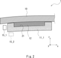
- 2 is a cross-sectional view of the vehicle glass plate shown in FIG. 1 along line II-II.
- FIG. 2 is a plan view showing a configuration example of an optical element.
- FIG. 2 is a cross-sectional view showing a configuration example of an optical element.
- FIG. 2 is a cross-sectional view showing a configuration example of an optical element.
- FIG. 2 is a cross-sectional view showing a configuration example of an optical element.
- FIG. 2 is a cross-sectional view showing a configuration example of an optical element.
- FIG. 2 is a cross-sectional view showing a configuration example of an optical element.
- FIG. 2 is a cross-sectional view showing a configuration example of an optical element.
- FIG. 2 is a cross-sectional view showing a configuration example of an optical element.
- FIG. 2 is a cross-sectional view showing a
- FIG. 1 is a cross-sectional view showing an example of a configuration of a glass plate for a vehicle according to an embodiment.
- FIG. 1 is a cross-sectional view showing an example of a configuration of a glass plate for a vehicle according to an embodiment.
- FIG. 1 is a cross-sectional view showing an example of a configuration of a glass plate for a vehicle according to an embodiment.
- FIG. 2 is a plan view showing a configuration example of an optical element.
- FIG. 2 is a plan view showing a configuration example of an optical element.
- FIG. 2 is a plan view showing a configuration example of an optical element.
- FIG. 2 is a plan view showing a configuration example of an optical element.
- FIG. 2 is a plan view showing a configuration example of an optical element.
- FIG. 2 is a plan view showing a configuration example of an optical element.
- FIG. 2 is a plan view showing a configuration example of an optical element.
- FIG. 2 is a plan view showing a configuration
- FIG. 2 is a plan view showing a configuration example of an optical element.
- FIG. 2 is a plan view showing a configuration example of an optical element.
- FIG. 2 is a plan view showing a configuration example of an optical element.
- FIG. 2 is a cross-sectional view illustrating a method for manufacturing a glass plate for a vehicle according to an embodiment.
- FIG. 1 is a plan view showing a configuration example of a vehicle glass plate according to an embodiment.
- FIG. 2 is a cross-sectional view of the vehicle glass plate shown in FIG. 1 along the cutting line II-II.
- the vehicle glass plate 1 according to the embodiment includes a glass plate 10 and optical elements 11_1 and 11_2.
- the optical element 11_1 is bonded to the surface of the glass plate 10 using an adhesive member 12.
- the optical element 11_2 is bonded to the surface of the glass plate 10 using an adhesive member 12.
- the optical elements 11_1 and 11_2 are also collectively referred to as the optical element 11. The same applies to other components.
- the vehicle glass plate 1 can be used, for example, as a vehicle window.
- vehicle windows include roof glass, windshields, side windows, rear windows, and the like.
- the vehicle glass plate 1 can be configured to introduce irradiation light from an end of the vehicle glass plate 1 into the interior of the vehicle glass plate using a light source such as an LED, and to scatter the light on the surface or inside of the vehicle glass plate and extract the light to the outside.
- a light source such as an LED
- the ceiling part inside the vehicle can be illuminated in a predetermined color, improving the design inside the vehicle.
- Information notification includes, for example, a danger alert and a notification of the vehicle status, but is not limited to these.
- the light extracted to the outside of the vehicle glass plate 1 can be used for various purposes depending on the mounting position of the vehicle glass plate 1 on the vehicle.
- the glass plate 10 has a rectangular shape with the y-axis direction as the longitudinal direction. Also, as shown in FIG. 2, the glass plate 10 has a curved shape. Specifically, the glass plate 10 may have a single curved shape curved in one direction, or a three-dimensional shape curved in two or more directions. The three-dimensional shape may be, for example, a compound curved shape curved in two perpendicular directions. Note that in the drawings other than FIG. 2, the glass plate 10 is shown in an uncurved state to simplify the drawings, but the glass plate 10 used in this embodiment has a curved shape.
- the glass plate 10 used in this embodiment may be a single glass plate or may be laminated glass.
- the glass plate 10 includes a first glass plate, a second glass plate, and an intermediate adhesive layer disposed between the first glass plate and the second glass plate.
- the first and second glass plates can be made of, for example, transparent inorganic glass.
- first and second glass plates for example, soda lime glass, aluminosilicate glass, borosilicate glass, alkali-free glass, quartz glass, etc. may be used.
- the first and second glass plates are manufactured using, for example, the float method, the fusion method, etc., but are not limited to these manufacturing methods.
- the thickness of the glass plate is preferably 1.5 mm to 10 mm.
- the thickness of the glass plate may be, for example, 1.8 mm or more, 2.5 mm or more, or 2.8 mm or more.
- the thickness of the glass plate may be 6 mm or less, 4 mm or less, 3.1 mm or less, or 2.3 mm or less.
- the upper and lower limits of the above numerical ranges may be combined in any way, and may be, for example, 2.4 mm to 4 mm.
- the thickness of each of the first and second glass plates is, for example, 0.1 mm to 10 mm, and is preferably 0.3 mm or more, and more preferably 0.5 mm or more, from the viewpoint of resistance to flying stone impact.
- the thickness of each of the first and second glass plates is preferably 3 mm or less, more preferably 2.6 mm or less, and even more preferably 2.1 mm or less.
- the upper and lower limits of the above numerical ranges can be combined arbitrarily, and may be, for example, 0.3 mm to 3.0 mm, 1.1 mm to 2.6 mm, or 1.7 mm to 2.1 mm.
- the thicknesses of the first and second glass plates may be the same or different from each other.
- the thickness of the first glass plate arranged on the outside of the vehicle may be thicker than the thickness of the second glass plate arranged on the inside of the vehicle. In this way, when the thickness of the first glass plate arranged on the outside of the vehicle is thickened, the strength of the glass plate 10 against objects flying toward the vehicle window glass plate 1 is improved.
- the intermediate adhesive layer is disposed so as to be sandwiched between the first glass plate and the second glass plate.
- the thickness of the intermediate adhesive layer is not particularly limited, but is, for example, 0.3 mm to 3 mm.
- the thickness of the intermediate adhesive layer is preferably 2.40 mm or less, and more preferably 1.10 mm or less.
- the thickness of the intermediate adhesive layer is preferably 0.50 mm or more, and more preferably 0.70 mm or more.
- the intermediate adhesive layer is preferably made of a thermoplastic resin or a curable resin, with a thermoplastic resin being particularly preferred.
- the intermediate adhesive layer can be made of polyvinyl butyral (PVB) resin, ethylene vinyl acetate copolymer (EVA) resin, polyurethane resin, ionomer resin, cycloolefin polymer, etc.
- PVB resin polyvinyl butyral
- EVA resin ethylene vinyl acetate copolymer
- polyurethane resin polyurethane resin
- ionomer resin ionomer resin
- cycloolefin polymer cycloolefin polymer
- the optical elements 11_1 and 11_2 are bonded to the surface of the glass plate 10 using an adhesive member 12.
- two optical elements 11_1 and 11_2 extending in the y-axis direction are provided near the end of the glass plate 10 on the negative side in the x-axis direction and near the end on the positive side in the x-axis direction, respectively.
- a light source 15_1 is provided near the end of the optical element 11_1 on the negative side in the x-axis direction. This allows light from the light source 15_1 to be introduced to the end of the vehicle glass plate 1 on the negative side in the x-axis direction via the optical element 11_1.
- the light source may be placed at the position of light source 15_2, or two light sources may be provided at the positions of light source 15_1 and light source 15_2.
- the optical element 11 has, for example, a rectangular parallelepiped shape, a triangular prism shape, or a trapezoidal prism shape. In this embodiment, the optical element 11 has a rectangular parallelepiped shape as an example. Each surface constituting the optical element 11 may be curved, and the corners may be curved.
- the optical element 11 is made of glass or a resin material. For example, polycarbonate, acrylic resin, epoxy resin, silicone rubber, etc. may be used as the resin material. Since the resin material is an elastic body, when the optical element 11 is made of a resin material, the optical element 11 can be made of an elastic body.
- the optical element 11 may be curved in advance to match the curved shape of the surface of the glass plate 10.
- the optical element 11 when the optical element 11 is made of a material that is difficult to deform, the optical element 11 is curved in advance to match the curved shape of the surface of the glass plate 10. Since a glass plate with a thickness of 2 mm or more is difficult to deform at room temperature, the optical element 11 needs to be thermally bent in advance to be formed into a curved shape.
- the optical element 11 when the optical element 11 is constructed using a glass plate having a thickness of less than 2 mm, preferably 1.4 mm or less, and more preferably 1 mm or less, the optical element 11 can be elastically deformed to fit the curved shape of the surface of the glass plate 10 at room temperature. It is particularly preferable to subject such glass plates to a strengthening treatment such as chemical strengthening.
- the optical element 11 may be colored to the extent that the effect of the present disclosure is not impaired.
- the refractive index of the optical element 11 is close to the refractive index of the glass plate 10. For example, if the refractive index of the glass plate 10 is about 1.52, it is preferable that the refractive index of the optical element 11 is about 1.45 or more and 1.60 or less.
- a groove 21 is formed in at least a part of the main surface of the optical element 11 facing the glass plate (the main surface on the positive side in the z-axis direction), and at least a part of the groove 21 is connected to the outside on the side of the optical element.
- the optical element 11 is adhered to the glass plate 10 with the adhesive member 12 filled in the groove 21. Therefore, the optical element 11 also functions as a spacer that sets the adhesive member 12 to a predetermined thickness. This eliminates the need to prepare a separate spacer, and also prevents an increase in the interface between the members.
- FIG. 3 is a plan view showing an example of the configuration of an optical element.
- the optical element 11 has a groove portion 21 on the main surface on the positive side of the z-axis direction of the optical element 11.
- the depth of the groove portion 21 may be adjusted, for example, in the range of 30 ⁇ m to 3,000 ⁇ m depending on the thickness of the optical element 11 and the fluidity of the adhesive member 12 before hardening.
- the groove portion 21 is shallow in order to prevent the adhesive member 12 from excessively flowing out of the groove portion 21.
- the area of the groove portion 21 when viewed in plan from the z-axis direction is preferably 30% to 95% of the area of the optical element 11, and may be, for example, 50% to 90% or 70% to 80%.
- the length (width) of the optical element 11 in the x-axis direction is 10 mm or more and 50 mm or less
- the length of the optical element 11 in the y-axis direction is 50 mm or more and 900 mm or less
- the length (thickness) of the optical element 11 in the z-axis direction is 0.5 mm or more and 10 mm or less.
- the size of the optical element 11 may be other than these.
- the width of the optical element 11 may be 15 mm or more, or 20 mm or more.
- the width of the optical element 11 may be 40 mm or less, or 30 mm or less.
- the length of the optical element 11 may be 100 mm or more, 150 mm or more, or 300 mm or more.
- the length of the optical element 11 may be 700 mm or less, or 500 mm or less.
- the thickness of the optical element 11 is preferably 0.7 mm or more, and more preferably 1 mm or more. This thickness makes it easier to form a groove sufficient for adhesion, and durability is less likely to decrease.
- the thickness of the optical element 11 is preferably 5 mm or less, more preferably 3 mm or less, and even more preferably 2.1 mm or less. This thickness prevents the light guide efficiency from decreasing too much, and makes it easier to follow curved shapes.
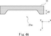
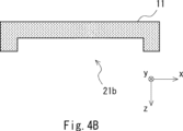
- FIG. 4A to 4C are cross-sectional views showing examples of the configuration of an optical element, and are cross-sectional views of the optical element 11 shown in FIG. 3 along the cutting line IV-IV, in other words, cross-sectional views of a portion of the optical element 11 including the groove portion 21.
- the cross-sectional shape of the groove portion 21a may be trapezoidal.
- the cross-sectional shape of the groove portion 21b may be rectangular.
- the cross-sectional shape of the groove portion 21c may be a shape in which the corners away from the glass plate 10 (i.e., at the position on the negative side in the z-axis direction) are curved.
- the cross-sectional shape of the groove portion 21 is a trapezoid as shown in FIG. 4A or a shape in which the corners are curved as shown in FIG. 4C, it is easy to fill the corners of the groove portion 21 with the adhesive member 12 without gaps. Therefore, it is possible to reduce the occurrence of cavities between the optical element 11 and the adhesive member 12.
- the groove 21 of the optical element 11 is connected to the outside at a side of the optical element 11 other than the side on which the light source 15 is attached.
- the light source 15 is attached along the side of the optical element 11 on the negative side in the x-axis direction.
- the groove 21 of the optical element 11 is connected to the outside via holes 22, 23, and 24 provided in the side of the optical element 11. Connected to the outside means that the groove 21 is spatially continuous with the external space via the holes 22, 23, and 24.
- the adhesive member 12 is filled in the groove 21, the adhesive member 12 is also filled in at least a portion of the holes 22, 23, and 24.
- the adhesive member 12 can be made of a transparent adhesive, specifically, an optically transparent adhesive (OCR: Optical Clear Resin).
- OCR optical Clear Resin
- the optically transparent adhesive is a curing adhesive, and has fluidity before curing.
- an acrylate-based, silicone-based, urethane-based, urethane acrylate-based, epoxy-based, epoxy acrylate-based, acrylamide-based, or methacrylamide-based resin composition can be used for the adhesive member 12.
- the adhesive member 12 is an adhesive member that transmits at least visible light, and in this embodiment, an ultraviolet-curing resin may be used.
- a thermosetting resin or a reaction-curing resin may be used as the adhesive member 12.
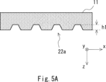
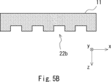
- 5A to 5C are cross-sectional views showing examples of the configuration of an optical element, and are cross-sectional views of the optical element 11 at the cutting line V-V shown in FIG. 3, in other words, cross-sectional views of a portion including the hole 22 of the optical element 11.
- the cross-sectional shape of the hole 22a may be trapezoidal.
- the cross-sectional shape of the hole 22b may be rectangular.
- the cross-sectional shape of the hole 22c may be semicircular.
- the height of the hole 22 provided on the side surface of the optical element 11 is approximately the same as the depth of the groove 21 of the optical element 11.
- the height h1 of the hole 22a shown in FIG. 5A and the depth d1 of the groove 21a shown in FIG. 4A are approximately the same. Also, in this embodiment, the height h1 of the hole 22a may be lower than the depth d1 of the groove 21a shown in FIG. 4A.
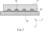
- FIGS. 6 to 8 are cross-sectional views showing an example of the configuration of a glass plate for a vehicle according to this embodiment, and are cross-sectional views for explaining the state in which an optical element 11 is adhered to the surface of a glass plate 10 using an adhesive member 12.
- FIG. 6 corresponds to the cross-sectional view of the optical element 11 shown in FIG. 3 taken along the section line IV-IV
- FIG. 7 corresponds to the cross-sectional view of the optical element 11 shown in FIG. 3 taken along the section line V-V
- FIG. 8 corresponds to the cross-sectional view of the optical element 11 shown in FIG. 3 taken along the section line VIII-VIII.
- the adhesive member 12 may be thinly provided between the optical element 11 and the glass plate 10 at each of the locations on the positive side in the x-axis direction and the negative side in the x-axis direction of the optical element 11.
- the adhesive member 12 may be thinly provided between the optical element 11 and the glass plate 10 at the location where the groove 21 of the optical element 11 is not provided.
- the thickness of the adhesive member 12 between the optical element 11 and the glass plate 10 at this location may be sufficiently smaller than the thickness at the location where the groove 21 is provided, and may be substantially close to zero. In this embodiment, the adhesive member 12 is less likely to protrude to the outside at this location during manufacturing.
- the optical element 11 is bonded to the glass plate 10 in a state where the adhesive member 12 is filled in the hole 22 at a location corresponding to the cutting line V-V of the optical element 11 shown in FIG. 3.
- the optical element 11 is bonded to the glass plate 10 in a state where the adhesive member 12 filled in the groove 21 reaches the hole 22.
- the adhesive member 12 may be thinly provided between the optical element 11 and the glass plate 10, in other words, between the optical element 11 and the glass plate 10 at a location where the hole 22 of the optical element 11 is not provided.
- the optical element 11 is adhered to the glass plate 10 using an adhesive member 12.
- the adhesive member 12 may be thinly provided between the optical element 11 and the glass plate 10.
- FIG. 6 to 8 show an example of a configuration in which a thin adhesive member 12 is provided between the optical element 11 and the glass plate 10 in areas other than where the grooves 21 and holes 22 are provided.
- the adhesive member 12 may not be provided between the optical element 11 and the glass plate 10 in areas other than where the grooves 21 and holes 22 are provided.
- the space between the optical element 11 and the glass plate 10 may be hollow, or a member other than the adhesive member 12 (e.g., a different adhesive member) may be provided.
- the optical element 11 and the glass plate 10 may also be in direct contact with each other.
- the groove 21 is formed in at least a part of the main surface of the optical element 11 facing the glass plate 10, and at least a part of the groove 21 is configured to be connected to the outside on the side surface of the optical element 11.
- the optical element 11 is bonded to the glass plate 10 with the adhesive member 12 filled in the groove 21 of the optical element 11.
- the adhesive member 12 is filled in the groove 21, and excess adhesive member 12 leaks out from the holes 22, 23, and 24 to the outside, so that the thickness of the adhesive member 12 between the glass plate 10 and the optical element 11 can be made uniform. Therefore, even if the glass plate 10 is curved, the optical element 11 can be appropriately attached to the curved glass plate 10. In addition, the individual difference (variation) in the thickness of the adhesive member 12 between the glass plate 10 and the optical element 11 can also be reduced.
- holes 22 and 23 may be formed on side surfaces facing each other in the longitudinal direction of the optical element 11a when the optical element 11a is viewed in a plan view.
- hole 22 may be formed on the side surface of the optical element 11a on the positive side in the y-axis direction
- hole 23 may be formed on the side surface of the optical element 11a on the negative side in the y-axis direction.
- the optical element 11a shown in FIG. 9 differs from the optical element 11 shown in FIG. 3 in that hole 24 is not formed on the side surface on the positive side in the x-axis direction.
- a hole 24 may be formed on one of the side surfaces that face each other in the short direction of the optical element 11b.
- the hole 24 may be formed on the side surface on the positive side of the x-axis direction of the optical element 11b.
- a light source is provided on the other side surface that faces each other in the short direction of the optical element 11b.
- the optical element 11b shown in FIG. 10 differs from the optical element 11 shown in FIG. 3 in that holes 22, 23 are not formed on the side surface on the positive side of the y-axis direction and the side surface on the negative side of the y-axis direction.
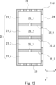
- the groove portion 21 may be provided with beam portions 25_1 to 25_3 extending in a direction intersecting the longitudinal direction of the optical element 11c.
- the beam portions 25_1 to 25_3 extending in the x-axis direction may be formed inside the groove portion 21.
- each of the groove portions 21_1 to 21_4 may be configured to be connected to the outside via at least one of the holes 22, 23, and 24.
- the position of the light source 15 is separated from the position of the beam portion 25. This can reduce scattering of light from the light source 15 by the beam portion 25.
- the beam portions 25_1 to 25_3 may be provided with communication openings 26_1 to 26_3, and the groove portions 21_1 to 21_4 divided by the beam portions 25_1 to 25_3 may be connected to each other via the communication openings 26_1 to 26_3.
- the adhesive material 12 filled in each of the groove portions 21_1 to 21_4 can be made uniform.
- FIG. 12 shows a configuration example in which the communication openings 26_1 to 26_3 are provided in the center of each of the beam portions 25_1 to 25_3, the positions at which the communication openings 26_1 to 26_3 are formed can be determined arbitrarily.
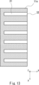
- a configuration may be used in which multiple grooves 31 extending in the x-axis direction are formed.
- a hole 32 is provided at the end of the groove 31 on the positive side in the x-axis direction.
- the groove 31 is connected to the outside on the side surface on the positive side in the x-axis direction of the optical element 11e, and the end of the groove 31 forms the hole 32.
- a configuration may be used in which a groove portion 33 extending in the y-axis direction is formed, as in optical element 11f shown in FIG. 14.
- a hole portion 34 is provided at the end of groove portion 33 on the positive side in the y-axis direction
- a hole portion 35 is provided at the end of groove portion 33 on the negative side in the y-axis direction.
- groove portion 33 is connected to the outside at the side surface of optical element 11f on the positive side in the y-axis direction
- groove portion 33 is connected to the outside at the side surface of optical element 11f on the negative side in the y-axis direction
- each end of groove portion 33 forms hole portions 34, 35.
- the configuration shown in FIG. 13 may be combined with the configuration shown in FIG. 14. That is, as in the optical element 11g shown in FIG. 15, a configuration may be used that includes a groove portion 33 extending in the y-axis direction and multiple groove portions 31 extending in the x-axis direction and connected to the groove portion 33.
- a hole portion 32 is provided at the end of the groove portion 31 on the positive side in the x-axis direction
- a hole portion 34 is provided at the end of the groove portion 33 on the positive side in the y-axis direction
- a hole portion 35 is provided at the end of the groove portion 33 on the negative side in the y-axis direction. Note that the position where the groove portion 33 is connected to the multiple groove portions 31 is not limited to the end of the multiple groove portions 31.
- any configuration may be used as long as a groove is formed in at least a part of the main surface of the optical element 11 facing the glass plate 10, and at least a part of the groove is connected to the outside on the side surface of the optical element 11.
- the grooves 31 and 33 may be arranged in a curved shape rather than a straight line.
- a through hole penetrating in the thickness direction may be further provided in the main surface of the optical element 11.
- excess adhesive material 12 can escape to the outside through both the hole portion 22 and the through hole.
- the through hole is preferably provided in a position on the main surface of the optical element 11 that does not affect (or has little effect on) the optical properties of the optical element 11.
- the through hole provided in the main surface of the optical element 11 may also be used to fix other members, such as a cover, to the vehicle glass plate.
- Figure 16 is a cross-sectional view for explaining an example of a method for manufacturing a vehicle glass plate according to the present embodiment, showing a portion of the vehicle glass plate.
- an optical element 11 having a groove 21 formed therein is prepared.
- the optical element described above is used for the optical element 11.
- an adhesive member 12 is applied to the curved glass plate 10 or the groove 21 of the optical element 11.
- the upper diagram of FIG. 16 illustrates a case where the adhesive member 12 has been applied to the groove 21 of the optical element 11.
- the adhesive member 12 may be applied continuously along the longitudinal direction of the groove 21.
- the adhesive member 12 may also be applied to multiple locations along the longitudinal direction of the groove 21 of the optical element 11.
- the adhesive member 12 When applying the adhesive member 12 to the glass plate 10, the adhesive member 12 is applied at a position such that the adhesive member 12 applied to the glass plate 10 fills the grooves 21 of the optical element 11 when the glass plate 10 and the optical element 11 are bonded together.
- the adhesive member 12 may be applied to both the glass plate 10 and the grooves 21 of the optical element 11.
- the optical element 11 is bonded to the glass plate 10. That is, as shown in the center diagram of FIG. 16, the optical element 11 is pressed against the glass plate 10 with the main surface of the glass plate 10 facing the surface of the optical element 11 on which the grooves 21 are formed (the surface on which the adhesive member 12 is applied). After that, the adhesive member 12 is cured to bond the optical element 11 to the curved glass plate 10.
- the adhesive member 12 is an ultraviolet curing resin, as shown in the lower diagram of FIG. 16, the adhesive member 12 is cured by irradiating ultraviolet rays UV from the surface of the optical element 11 opposite to the surface on which the adhesive member 12 is applied.
- the adhesive member 12 may be cured by irradiating ultraviolet rays through the glass plate 10, or the adhesive member 12 may be cured by both ultraviolet irradiation from the surface of the optical element 11 opposite to the surface on which the adhesive member 12 is applied and ultraviolet irradiation through the glass plate 10.
- the groove 21 of the optical element 11 is connected to the outside on the side surface of the optical element 11. Therefore, as shown in the center diagram of FIG. 16, in the process of adhering the optical element 11 to the glass plate 10, when the optical element 11 is pressed against the glass plate 10, a portion of the adhesive member 12 protrudes from the hole 24 provided on the side surface of the optical element 11. In this embodiment, after the adhesive member 12 protrudes from the side surface of the optical element 11, the adhesive member 12 is cured to adhere the optical element 11 to the glass plate 10. In this way, the optical element 11 can be adhered to the glass plate 10 with the adhesive member 12 permeating the entire groove 21 of the optical element 11, so that the occurrence of cavities between the optical element 11 and the adhesive member 12 can be reduced.
- the adhesive member 12 may be cured in a state where the adhesive member 12 protrudes from the side surface of the optical element 11, and the state of the adhesive member 12 in this protruding portion may be checked to determine the degree of adhesion between the glass plate 10 and the optical element 11. For example, when the adhesive member 12 is cured, the volume of the adhesive member 12 decreases. In this embodiment, this property may be utilized to cure the adhesive member 12 in a state where the adhesive member 12 protrudes from the side surface of the optical element 11 (see the portion indicated by reference numeral 41 in the central drawing of FIG.
- the degree of adhesion between the glass plate 10 and the optical element 11 may be determined by checking that the adhesive member 12 in this protruding portion has been reduced (see the portion indicated by reference numeral 42 in the lower drawing of FIG. 16). In this case, when the adhesive member 12 is cured and the volume of the adhesive member 12 is reduced, the adhesive member 12 present in the hole portion 24 is replenished in the groove portion 21 (see the portion indicated by reference numeral 42 in the lower drawing of FIG. 16). This reduces the risk of air getting into the groove 21 when the adhesive member 12 hardens.
- the optical element 11 may be configured using an elastic body. In this case, the optical element 11 is pressed against the glass plate 10, the optical element 11 is elastically deformed, and then the adhesive member 12 is hardened, thereby adhering the optical element 11 to the glass plate 10.
- the manufacturing method for vehicle glass plates according to the present embodiment described above allows optical elements to be properly attached to curved glass plates.
Landscapes
- Engineering & Computer Science (AREA)
- Mechanical Engineering (AREA)
- Joining Of Glass To Other Materials (AREA)
Abstract
L'invention concerne une plaque de verre de véhicule qui permet à un élément optique d'être correctement fixé à une plaque de verre incurvée. Une plaque de verre de véhicule selon un mode de réalisation de la présente invention comprend : une plaque de verre incurvée ; et un élément optique lié à une surface de la plaque de verre à l'aide d'un élément adhésif. Une rainure est formée dans au moins une partie d'une surface principale de l'élément optique qui fait face à la plaque de verre, et au moins une partie de la rainure est contiguë à l'extérieur sur une surface latérale de l'élément optique. L'élément optique est lié à la plaque de verre dans un état dans lequel la rainure est remplie par l'élément adhésif.
Priority Applications (2)
| Application Number | Priority Date | Filing Date | Title |
|---|---|---|---|
| JP2025526097A JPWO2024253056A1 (fr) | 2023-06-06 | 2024-06-03 | |
| CN202480037520.1A CN121335813A (zh) | 2023-06-06 | 2024-06-03 | 车辆用玻璃板和车辆用玻璃板的制造方法 |
Applications Claiming Priority (2)
| Application Number | Priority Date | Filing Date | Title |
|---|---|---|---|
| JP2023-093153 | 2023-06-06 | ||
| JP2023093153 | 2023-06-06 |
Publications (1)
| Publication Number | Publication Date |
|---|---|
| WO2024253056A1 true WO2024253056A1 (fr) | 2024-12-12 |
Family
ID=93795960
Family Applications (1)
| Application Number | Title | Priority Date | Filing Date |
|---|---|---|---|
| PCT/JP2024/020168 Ceased WO2024253056A1 (fr) | 2023-06-06 | 2024-06-03 | Plaque de verre de véhicule et procédé de fabrication de plaque de verre de véhicule |
Country Status (3)
| Country | Link |
|---|---|
| JP (1) | JPWO2024253056A1 (fr) |
| CN (1) | CN121335813A (fr) |
| WO (1) | WO2024253056A1 (fr) |
Citations (5)
| Publication number | Priority date | Publication date | Assignee | Title |
|---|---|---|---|---|
| JPS61198247U (fr) * | 1985-05-24 | 1986-12-11 | ||
| JP2005187493A (ja) * | 2003-12-24 | 2005-07-14 | Hori Glass Kk | 接着方法及び接着構造 |
| JP2010014147A (ja) * | 2008-07-01 | 2010-01-21 | Piolax Inc | ガラス仮固定用クリップ |
| JP2021181403A (ja) * | 2019-02-20 | 2021-11-25 | Agc株式会社 | 合わせガラス |
| JP2023520153A (ja) * | 2020-04-03 | 2023-05-16 | ベバスト エスエー | 光源及び導光層を備える車両窓ガラス |
-
2024
- 2024-06-03 WO PCT/JP2024/020168 patent/WO2024253056A1/fr not_active Ceased
- 2024-06-03 JP JP2025526097A patent/JPWO2024253056A1/ja active Pending
- 2024-06-03 CN CN202480037520.1A patent/CN121335813A/zh active Pending
Patent Citations (5)
| Publication number | Priority date | Publication date | Assignee | Title |
|---|---|---|---|---|
| JPS61198247U (fr) * | 1985-05-24 | 1986-12-11 | ||
| JP2005187493A (ja) * | 2003-12-24 | 2005-07-14 | Hori Glass Kk | 接着方法及び接着構造 |
| JP2010014147A (ja) * | 2008-07-01 | 2010-01-21 | Piolax Inc | ガラス仮固定用クリップ |
| JP2021181403A (ja) * | 2019-02-20 | 2021-11-25 | Agc株式会社 | 合わせガラス |
| JP2023520153A (ja) * | 2020-04-03 | 2023-05-16 | ベバスト エスエー | 光源及び導光層を備える車両窓ガラス |
Also Published As
| Publication number | Publication date |
|---|---|
| JPWO2024253056A1 (fr) | 2024-12-12 |
| CN121335813A (zh) | 2026-01-13 |
Similar Documents
| Publication | Publication Date | Title |
|---|---|---|
| CN103770696B (zh) | 交通工具装配玻璃 | |
| KR101276504B1 (ko) | 접착 방법, 접착 구조, 광학 모듈의 제조 방법 및 광학 모듈 | |
| US9630551B2 (en) | Light-emitting diode module for a vehicle, and productions | |
| US12011914B2 (en) | Curved glass constructions and methods for forming same | |
| US20110273874A1 (en) | Light-emitting diode module for a vehicle, and diode mounting | |
| CN117677491A (zh) | 车辆发光装配玻璃及其制造 | |
| CN112677575A (zh) | 导光天窗总成 | |
| JP7643458B2 (ja) | 車両用窓構造 | |
| US12233778B2 (en) | Transparent roof panel assembly for a vehicle roof | |
| CN119855701A (zh) | 用于车辆的发光装配玻璃、其制造、以及包括此类发光装配玻璃的车辆 | |
| US20230032295A1 (en) | Window glass for vehicle | |
| US20230070299A1 (en) | Glass unit for an illuminated vehicle roof, method of manufacturing a glass unit, and illuminated vehicle roof | |
| CN118742524A (zh) | 车辆用夹层玻璃 | |
| US20200130327A1 (en) | Glass resin laminate | |
| CN121335813A (zh) | 车辆用玻璃板和车辆用玻璃板的制造方法 | |
| JP2021113146A (ja) | ガラス積層体およびその製造方法 | |
| CN115551707B (zh) | 包括发光二极管模块、支撑板的车辆组件和用于组装这种组件的方法 | |
| JP2026007445A (ja) | 車両用ガラス板、及び車両用ガラス板の製造方法 | |
| CN215850676U (zh) | 天窗用发光装置 | |
| JP2020027738A (ja) | 光源付きガラス板、及び合わせガラス | |
| JP7797932B2 (ja) | 車両窓用窓ガラス | |
| CN119451811A (zh) | 用于车辆的发光装配玻璃、以及包括此类发光装配玻璃的车辆 | |
| JP7810181B2 (ja) | ブラケット、及び情報取得モジュール | |
| US20260093065A1 (en) | Illuminable glazing with multilayer light coupling means | |
| WO2024033772A1 (fr) | Vitrage ayant un ensemble d'injection de lumière |
Legal Events
| Date | Code | Title | Description |
|---|---|---|---|
| 121 | Ep: the epo has been informed by wipo that ep was designated in this application |
Ref document number: 24819286 Country of ref document: EP Kind code of ref document: A1 |
|
| ENP | Entry into the national phase |
Ref document number: 2025526097 Country of ref document: JP Kind code of ref document: A |
|
| NENP | Non-entry into the national phase |
Ref country code: DE |