WO2024253062A1 - Vehicle travel direction detection device - Google Patents
Vehicle travel direction detection device Download PDFInfo
- Publication number
- WO2024253062A1 WO2024253062A1 PCT/JP2024/020213 JP2024020213W WO2024253062A1 WO 2024253062 A1 WO2024253062 A1 WO 2024253062A1 JP 2024020213 W JP2024020213 W JP 2024020213W WO 2024253062 A1 WO2024253062 A1 WO 2024253062A1
- Authority
- WO
- WIPO (PCT)
- Prior art keywords
- vehicle
- acceleration
- axis
- detection device
- angle
- Prior art date
- Legal status (The legal status is an assumption and is not a legal conclusion. Google has not performed a legal analysis and makes no representation as to the accuracy of the status listed.)
- Ceased
Links
Images





Classifications
-
- B—PERFORMING OPERATIONS; TRANSPORTING
- B62—LAND VEHICLES FOR TRAVELLING OTHERWISE THAN ON RAILS
- B62D—MOTOR VEHICLES; TRAILERS
- B62D6/00—Arrangements for automatically controlling steering depending on driving conditions sensed and responded to, e.g. control circuits
-
- B—PERFORMING OPERATIONS; TRANSPORTING
- B62—LAND VEHICLES FOR TRAVELLING OTHERWISE THAN ON RAILS
- B62D—MOTOR VEHICLES; TRAILERS
- B62D9/00—Steering deflectable wheels not otherwise provided for
Definitions
- This disclosure relates to a vehicle travel direction detection device.
- the vehicle slip angle detection device disclosed in Patent Document 1 detects the slip angle of the vehicle using an angular velocity (gyro) sensor and an acceleration sensor provided in the sensor unit.
- Patent Document 1 is capable of detecting straight-line travel or turning in a general vehicle, but is unable to detect the direction of diagonal movement relative to the vehicle's front and rear axles, which is unique to independently steered vehicles.
- vehicle includes, from a technical point of view, any moving object capable of traveling on the ground using wheels, regardless of legal classification regarding travel on public roads. For example, green slow mobility and AGVs (automated guided vehicles) are also included in the term "vehicle.”
- the objective of this disclosure is to provide a vehicle travel direction detection device that detects the direction of diagonal movement relative to the vehicle's front and rear axes in an independently steering vehicle.
- a vehicle to which the vehicle travel direction detection device according to the present disclosure is applied has three or more tires, and each tire can be steered independently by the steering torque output by the steering actuator corresponding to each tire.
- acceleration occurs when the braking/driving force of each tire output by one or more braking/driving actuators is transmitted to the road surface. "Acceleration" includes negative acceleration during deceleration due to braking.
- the vehicle is equipped with a first acceleration sensor and a second acceleration sensor that respectively detect the acceleration of a first axis and a second axis that intersect with each other in a plane parallel to the road surface.
- the vehicle travel direction detection device detects the direction of travel of the diagonal movement relative to the front and rear axes of the vehicle and controls the traveling of the vehicle. In other words, the vehicle travel direction detection device not only detects the direction of travel, but also includes a function to control the traveling of the vehicle based on the detected information.
- the diagonal movement angle calculation unit calculates the diagonal movement angle, which is the angle of the traveling direction relative to the front-rear axis of the vehicle, based on the acceleration of the first axis obtained from the first acceleration sensor and the acceleration of the second axis obtained from the second acceleration sensor when the vehicle is braked or driven.
- the vehicle travel direction detection device disclosed herein can detect the direction of diagonal movement in an independently steering vehicle using two-axial acceleration detected during braking and driving.
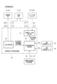
- FIG. 1 is a block diagram of a vehicle equipped with a vehicle travel direction detection device according to a first embodiment.
- FIG. 2A is a diagram showing diagonal movement in an independently steered vehicle;
- FIG. 2B is a diagram showing lateral movement in an independently steered vehicle;
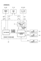
- FIG. 3 is a block diagram of a vehicle travel direction detection device according to a first embodiment;
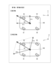
- FIG. 4 is a diagram for explaining acceleration that occurs when accelerating while traveling straight ahead and while traveling obliquely.
- FIG. 5 is a diagram showing the relationship between vehicle speed, X-axis acceleration, Y-axis acceleration, and diagonal movement angle.
- FIG. 6 is a flowchart showing a process performed by the vehicle travel direction detection device.
- FIG. 7 is a block diagram of a vehicle travel direction detection device according to a second embodiment;
- FIG. 8 is a diagram illustrating lateral acceleration due to turning.
- FIG. 9 is a block diagram of a vehicle travel direction detection device according to a third embodiment.
- FIG. 10 is a block diagram of a vehicle travel direction detection device according to a fourth embodiment.
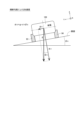
- FIG. 11 is a rear view of a vehicle illustrating the effect of a transverse gradient on acceleration;
- FIG. 12 is a side view of a vehicle illustrating the effect of a longitudinal gradient on acceleration;
- FIG. 13 is a diagram showing an arrangement of braking/driving actuators in another embodiment;
- FIG. 14 is a diagram showing an arrangement of braking/driving actuators in another embodiment;
- FIG. 15 is a diagram showing an example of setting the first axis and the second axis in another embodiment.
- the vehicle travel direction detection device of this embodiment is a device that detects the direction of diagonal movement relative to the front and rear axles of a vehicle in an independently steerable vehicle with three or more independently steerable tires, typically a four-wheel independently steerable vehicle.
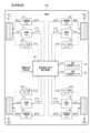
- the configuration of an independently steered vehicle 100 equipped with a vehicle travel direction detection device 20 of the first embodiment will be described with reference to Fig. 1.
- the vehicle 100 shown in Fig. 1 has four tires 91-94, and each tire 91-94 can be steered independently and can be independently braked and driven.
- the left front wheel 91 is marked “FL”
- the right front wheel 92 is marked “FR”
- the left rear wheel 93 is marked “RL”
- the right rear wheel 94 is marked "RR”.
- the symbols of each element below and the suffixes "1" to "4" in each symbol correspond to the FL, FR, RL, and RR tires 91-94, respectively.
- the vehicle 100 is equipped with steering actuators 71-74, braking/driving actuators 81-84, and tire angle sensors 671-674 that detect the actual tire angles (hereinafter "actual tire angles") corresponding to each of the tires 91-94.
- actuator is written as “Act.”
- the tire angle is expressed as 0 at the neutral position parallel to the vehicle's longitudinal axis, with the counterclockwise direction being positive and the clockwise direction from the neutral position being negative.
- the steering actuators 71-74 are configured integrally with a motor section such as a three-phase brushless motor including a stator and rotor wound with windings, and a motor drive device that controls the drive current passed through the windings.
- a motor section such as a three-phase brushless motor including a stator and rotor wound with windings, and a motor drive device that controls the drive current passed through the windings.
- Each tire 91-94 can be steered independently by the steering torques Tst1-Tst4 output by the steering actuators 71-74.
- the braking/driving actuators 81-84 are configured as a set of an electric brake as a braking actuator and an in-wheel motor as a driving actuator. Acceleration occurs when the braking/driving forces of each tire 91-94 output by the braking/driving actuators 81-84 are transmitted to the road surface.
- acceleration includes positive acceleration during acceleration due to driving, as well as negative acceleration during deceleration due to braking.
- the tire angle sensors 671-674 may be configured with an encoder or the like that directly detects the actual tire angle. Alternatively, if there is a correlation between the drive current of the steering actuators 71-74 and the tire angle, the drive current of the steering actuators 71-74 detected by the current sensor may be converted to the detected tire angles ⁇ s1- ⁇ s4 based on the current-torque characteristics and the torque transmission coefficient. In that case, the current sensor is considered to function as the tire angle sensor 671-674.
- first axis and a “second axis” that intersect with each other on a plane parallel to the road surface.
- the X-axis which is the front-rear axis (vertical axis) of the vehicle 100
- the Y-axis which is the left-right axis (horizontal axis) of the vehicle 100
- the first axis and the second axis are perpendicular to each other.
- the vehicle 100 is equipped with a first acceleration sensor 35 that detects the X-axis acceleration ⁇ x, which is the “acceleration of the first axis,” and a second acceleration sensor 36 that detects the Y-axis acceleration ⁇ y, which is the “acceleration of the second axis.”
- a movement direction indication value by a steering wheel operation by a driver or a steering signal of an autonomous vehicle is input to vehicle movement direction detection device 20. Based on the movement direction indication value, vehicle movement direction detection device 20 indicates target tire angles ⁇ * 1- ⁇ * 4 for steering actuators 71-74 and target braking/driving forces BD * 1-BD * 4 for braking/driving actuators 81-84.
- the vehicle travel direction detection device 20 calculates the "diagonal movement angle," which is the angle of the travel direction relative to the front and rear axes of the vehicle 100, based on the two-axis accelerations ⁇ x and ⁇ y obtained from the acceleration sensors 35 and 36 when the vehicle 100 is driven or braked (i.e., when driving or braking).
- vehicle traveling direction detection device 20 acquires detected tire angles ⁇ s1- ⁇ s4 of each of tires 91-94 detected by tire angle sensors 671-674. Vehicle traveling direction detection device 20 corrects target tire angles ⁇ * 1- ⁇ * 4 from the oblique movement angle and detected tire angles ⁇ s1- ⁇ s4, and instructs steering actuators 71-74 of the corrected target tire angles ⁇ ** 1- ⁇ ** 4.
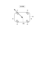
- diagonal movement as shown in FIG. 2A and lateral movement as shown in FIG. 2B are possible.
- all tires 91-94 are steered to the same tire angle with an absolute value of less than 90 degrees.
- lateral movement all tires 91-94 are steered to an absolute value of 90 degrees.
- diagonal movement is useful for changing driving lanes, and lateral movement is useful for parallel parking.
- the front side of the independently steering vehicle 100 is shown in a streamlined shape. The letters "front/rear" and "center of gravity" of the vehicle are only written in FIG. 2A and are omitted in subsequent figures.
- the purpose of this embodiment is to correctly detect the direction of diagonal movement relative to the vehicle's front and rear axes even when there is a detection error in the tire angle sensors 671-674 of the independently steered vehicle 100.
- the vehicle direction detection device 20 of this embodiment calculates the angle of diagonal movement based on the X-axis acceleration ⁇ x and Y-axis acceleration ⁇ y detected by the two-axis acceleration sensors 35, 36 when the vehicle 100 is accelerating or decelerating while braking or driving.
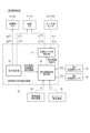
- the vehicle travel direction detection device 20 of the first embodiment has a driving instruction unit 25, a diagonal movement angle calculation unit 26, and, as an optional configuration, a target tire angle correction unit 27.
- the vehicle travel direction detection device 20 does not simply detect the direction of travel, but also includes a function of controlling vehicle travel based on the detected information.
- the basic configuration of the vehicle travel direction detection device 20 is the same as in the first embodiment, but it is mounted on a vehicle 100 further equipped with other additional devices, and processing using information obtained from the additional devices is added.
- driving instruction unit 25 instructs target tire angle ⁇ * 1- ⁇ * 4 for steering actuators 71-74 and target braking/driving force BD * 1-BD * 4 for braking/driving actuators 81-84.
- Driving instruction unit 25 also notifies driving angle and acceleration/deceleration instruction information to oblique movement angle calculation unit 26.
- Target tire angle ⁇ * 1- ⁇ * 4 is reflected in the driving angle instruction information
- target braking/driving force BD * 1-BD * 4 is reflected in the acceleration/deceleration instruction information.
- the diagonal movement angle calculation unit 26 recognizes that the vehicle 100 is being braked or driven based on acceleration/deceleration instruction information from the driving instruction unit 25.
- the diagonal movement angle calculation unit 26 acquires the X-axis acceleration ⁇ x from the first acceleration sensor 35 and the Y-axis acceleration ⁇ y from the second acceleration sensor 36.
- the diagonal movement angle calculation unit 26 calculates the diagonal movement angle ⁇ based on the acquired two-axis accelerations ⁇ x and ⁇ y.
- Vehicle acceleration ⁇ is the acceleration in the vehicle's forward direction on the XY plane that includes the X-axis and Y-axis.
- the forward direction of the X-axis is shown as positive.
- the acceleration when the acceleration of one of the first and second axes is in the vehicle travel direction, the acceleration may be calculated from the relationship between the vehicle drive torque and mass, or the time derivative of the wheel rotation speed.
- the vehicle acceleration ⁇ is calculated using equation (1.3), and the diagonal movement angle ⁇ is calculated using equation (1.4). Therefore, based on the two-axial accelerations ⁇ x and ⁇ y detected by the acceleration sensors 35 and 36, the diagonal movement angle ⁇ can be calculated, making it possible to determine whether the vehicle is traveling straight ahead or diagonally.
- the dashed line shows the CAE analysis results of vehicle speed V, X-axis acceleration ⁇ x, Y-axis acceleration ⁇ y, and diagonal movement angle ⁇ according to formula (1.4) when accelerating at a constant vehicle acceleration ⁇ while traveling diagonally
- the solid line shows the CAE analysis results of vehicle speed V, X-axis acceleration ⁇ x, Y-axis acceleration ⁇ y, and diagonal movement angle ⁇ according to formula (1.4) when traveling straight ahead, and when accelerating at a constant vehicle acceleration ⁇ while traveling diagonally.
- the vehicle acceleration ⁇ is commonly 1 [m/ s2 ]
- the traveling angle instruction value during diagonal traveling is 5 [deg].
- the X-axis acceleration ⁇ x When accelerating at a vehicle acceleration ⁇ of 1 [m/ s2 ] while traveling straight ahead, the X-axis acceleration ⁇ x is 1 [m/ s2 ] and the Y-axis acceleration ⁇ y is 0 [m/ s2 ].
- the X-axis acceleration ⁇ x when accelerating at a vehicle acceleration ⁇ of 1 [m/ s2 ] while traveling diagonally, the X-axis acceleration ⁇ x is 0.996 [m/ s2 ] and the Y-axis acceleration ⁇ y is 0.09 [m/ s2 ].
- the diagonal movement angle ⁇ calculated by equation (1.4) is equal to the traveling angle command value, 5 [deg].
- Target tire angle correction unit 27 stores the oblique movement angle ⁇ calculated by oblique movement angle calculation unit 26.
- Target tire angle correction unit 27 also acquires the detected tire angles ⁇ s1- ⁇ s4 of each tire 91-94 detected by tire angle sensors 671-674, and calculates the deviation (deviation) from the oblique movement angle ⁇ .
- Target tire angle correction unit 27 calculates corrected target tire angles ⁇ ** 1- ⁇ **4 by correcting the target tire angles ⁇ * 1- ⁇ * 4 of each tire 91-94 according to the deviation between the oblique movement angle ⁇ and the detected tire angles ⁇ s1- ⁇ s4 . Then, target tire angle correction unit 27 instructs steering actuators 71-74 of the corrected target tire angles ⁇ ** 1- ⁇ ** 4. In this way, the target tire angles ⁇ ** 1- ⁇ ** 4 are corrected by feedback control of the detected tire angles ⁇ s1- ⁇ s4.
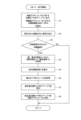
- the flowchart in Figure 6 shows the processing performed by the vehicle travel direction detection device 20.
- the symbol "S" means a step. This processing is repeatedly performed while the vehicle 100 is traveling, from when it starts traveling until it stops.
- the driving instruction unit 25 instructs the target tire angle ⁇ * 1- ⁇ * 4 for the steering actuators 71-74 and the target braking/driving forces BD * 1-BD * 4 for the braking/driving actuators 81-84 based on the movement direction instruction value.
- the vehicle 100 travels in the instructed movement direction according to the operation of the steering actuators 71-74 and the braking/driving actuators 81-84.
- S3 it is determined whether an acceleration/deceleration command based on the target braking/driving force BD * 1-BD * 4 is being output from the driving command unit 25, that is, whether the vehicle is currently in the braking/driving state. If an acceleration/deceleration command is not being output and the vehicle is traveling at a constant speed, the answer in S3 is NO and the routine ends. If an acceleration command based on driving or a deceleration command based on braking is being output, the answer in S3 is YES and the routine proceeds to S4.
- the diagonal movement angle calculation unit 26 acquires the X-axis acceleration ⁇ x from the first acceleration sensor 35 and acquires the Y-axis acceleration ⁇ y from the second acceleration sensor 36. In S5, the diagonal movement angle calculation unit 26 calculates the diagonal movement angle ⁇ based on the acquired X-axis acceleration ⁇ x and Y-axis acceleration ⁇ y.
- target tire angle correcting unit 27 acquires detected tire angles ⁇ s1- ⁇ s4 of each of tires 91-94.
- target tire angle correcting unit 27 calculates corrected target tire angles ⁇ **1- ⁇ **4 by correcting target tire angles ⁇ * 1- ⁇ * 4 of each of tires 91-94 in accordance with the deviation between oblique movement angle ⁇ calculated by oblique movement angle calculation unit 26 and detected tire angles ⁇ s1- ⁇ s4 .
- target tire angle correcting unit 27 instructs steering actuators 71-74 of corrected target tire angles ⁇ ** 1 - ⁇ ** 4.
- the vehicle travel direction detection device 20 calculates the diagonal movement angle ⁇ using the two-axial accelerations ⁇ x, ⁇ y detected during braking and driving in the independently steered vehicle 100. For example, even if the detected tire angles ⁇ s1- ⁇ s4 are misaligned with the actual tire angles due to improper installation of the tire angle sensors 671-674, the travel direction of the diagonal movement can be detected. This makes it possible to determine whether the travel direction of the vehicle 100 is the intended direction.
- the vehicle 100 can be moved in the intended direction without mechanically adjusting the alignment of the steering actuators 71-74.
- the vehicle travel direction detection device 20 is mounted on a vehicle equipped with a vehicle speed detection device 40 that detects a vehicle speed V, and a yaw rate detection device 45 that detects a yaw rate ⁇ of the vehicle.
- the oblique movement angle calculation unit 26 corrects the X-axis acceleration ⁇ x and the Y-axis acceleration ⁇ y using the vehicle speed V obtained from the vehicle speed detection device 40 and the yaw rate ⁇ obtained from the yaw rate detection device 45. Specifically, mainly the Y-axis acceleration ⁇ y is corrected.
- tire angles ⁇ 1, ⁇ 2, and ⁇ 3 other than the right rear wheel 94 are steered equally to the right, and only tire angle ⁇ 4 of the right rear wheel 94 is steered excessively to the right.
- the vehicle 100 turns counterclockwise while moving diagonally. In this way, when some tire angles deviate from the average tire angle of the entire vehicle, a turn (yaw motion) occurs, and the acceleration ⁇ yaw caused by the turn causes an error in the diagonal movement angle ⁇ .
- the yaw rate ⁇ [rad/s] is expressed by equation (2.1) using the vehicle speed V [m/s] and the turning radius R [m].
- the acceleration ⁇ yaw [m/ s2 ] due to turning is expressed by equation (2.2) using the vehicle speed V [m/s] and the yaw rate ⁇ [rad/s].
- the generated acceleration ⁇ yaw is 0.49 [m/ s2 ].
- the acceleration ⁇ yaw due to turning is calculated using the vehicle speed V and yaw rate ⁇ , and the accelerations ⁇ x and ⁇ y detected by the acceleration sensors 35 and 36 are corrected to remove the acceleration error due to turning, thereby improving the accuracy of the diagonal movement angle ⁇ .
- the diagonal movement angle calculation unit 26 corrects the X-axis acceleration ⁇ x and the Y-axis acceleration ⁇ y using the road gradient angle. In other words, the accuracy of the diagonal movement angle ⁇ can be improved by correcting the accelerations ⁇ x and ⁇ y detected by the acceleration sensors 35 and 36 to remove the error in the acceleration caused by the road gradient.
- the third and fourth embodiments may be combined with the second embodiment in which the accelerations ⁇ x and ⁇ y are corrected using the vehicle speed V and the yaw rate ⁇ .
- the third and fourth embodiments differ in the way in which the diagonal movement angle calculation unit 26 acquires the road gradient angle.
- the vehicle travel direction detection device 20 is mounted on a vehicle equipped with a road gradient angle detection device 50 that detects the road gradient angle.
- the road gradient angle detection device 50 detects the road gradient angle using map information containing road surface gradient information and a coordinate detection sensor (GPS).
- GPS coordinate detection sensor
- Fig. 11 which shows the rear view of the vehicle
- the gradient angle in a cross section perpendicular to the longitudinal axis of the vehicle 100 is represented as the transverse gradient angle ⁇ s.
- the acceleration ⁇ s due to the transverse gradient is expressed by equation (3.1) using the gravitational acceleration g ( ⁇ 9.8 [m/ s2 ]).
- the acceleration ⁇ s due to the transverse gradient is 0.2 [m/ s2 ].
- the gradient angle in a cross section along the longitudinal axis of the vehicle 100 is represented as the longitudinal gradient angle ⁇ f.
- the acceleration ⁇ f due to the longitudinal gradient is expressed by equation (3.2) using the gravitational acceleration g.
- the longitudinal gradient angle ⁇ f is 6.84 [deg] (gradient 12%)
- the acceleration ⁇ f due to the longitudinal gradient is 1.17 [m/ s2 ].
- the diagonal movement angle calculation unit 26 uses the road gradient angles ⁇ s and ⁇ f obtained from the road gradient angle detection device 50 to correct the X-axis acceleration ⁇ x and the Y-axis acceleration ⁇ y so as to remove the acceleration error caused by the road gradient.
- the vehicle travel direction detection device 20 is mounted on a vehicle equipped with a third acceleration sensor 37 that detects acceleration on a third axis perpendicular to the road surface.
- the third axis is perpendicular to the first and second axes on a plane parallel to the road surface, i.e., the X-axis and Y-axis in this embodiment.
- the third axis is represented as the Z-axis
- the acceleration on the third axis is represented as the Z-axis acceleration ⁇ z.
- the diagonal movement angle calculation unit 26 corrects the X-axis acceleration ⁇ x and the Y-axis acceleration ⁇ y using the road gradient angles ⁇ s and ⁇ f estimated based on the Z-axis acceleration ⁇ z obtained from the third acceleration sensor 37.
- the braking/driving actuators may be any actuators that generate acceleration in the vehicle 100 by transmitting the braking/driving force output to each tire 91-94 to the road surface, and may not be provided individually for each tire 91-94. In other words, each tire 91-94 is independently steered, but does not have to be independently braked or driven.
- the independently steered vehicle 105 shown in FIG. 13 is equipped with a front wheel braking/driving actuator 85 that outputs a common braking/driving force to the left and right front tires 91, 92, and a rear wheel braking/driving actuator 86 that outputs a common braking/driving force to the left and right rear tires 93, 94.
- the independently steered vehicle 107 shown in FIG. 14 is equipped with a four-wheel braking/driving actuator 87 that outputs a common braking/driving force to all four tires 91-94.
- the main motor or engine corresponds to the four-wheel driving actuator
- the hydraulic generating device that distributes brake hydraulic pressure to the four wheels corresponds to the four-wheel braking actuator.
- the vehicle travel direction detection device 20 is similarly applied to these vehicles 105 and 107.
- target braking/driving forces BD * 1 and BD * 2 have the same value
- target braking/driving forces BD * 3 and BD * 4 have the same value
- target braking/driving forces BD * 1-BD * 4 have the same value.
- the brakes for braking and the motors for driving do not necessarily have to be provided as a set.
- four electric brakes for braking may be provided for each tire, and two motors for driving may be provided, one for the left and right front wheels and one for the left and right rear wheels.
- the "first and second axes intersecting each other on a plane parallel to the road surface" along which acceleration is detected by the acceleration detection device are not limited to the mutually orthogonal X-axis and Y-axis.
- the p-axis and q-axis which are non-orthogonal axes, may be set as the first and second axes.
- the phase of the vehicle acceleration ⁇ which is a resultant vector of the p-axis acceleration ⁇ p and the q-axis acceleration ⁇ q, is calculated as the diagonal movement angle ⁇ .
- the vehicle travel direction detection device 20 is shown as a higher-level control device for the steering actuators 71-74. This configuration is not limiting, and the vehicle travel direction detection device 20 and the drive devices for each of the steering actuators 71-74 may function as a single unit. For example, the drive devices for the four steering actuators 71-74 may communicate information with each other to cooperate and realize the function of the vehicle travel direction detection device 20.
- An independently steered vehicle equipped with the vehicle travel direction detection device 20 is not limited to a four-wheeled vehicle, but may be any "vehicle with three or more wheels that can be steered independently," including three-wheeled vehicles, six-wheeled vehicles, etc.
- Vehicles include vehicles that run on public roads following the steering wheel operation by a driver or the steering signal of an automatic driving device, as well as green slow mobility and AGVs (automated guided vehicles) that run at low speeds in specific areas.
- a vehicle travel direction detection device mounted on a vehicle equipped with a vehicle speed detection device (40) that detects the vehicle speed and a yaw rate detection device (45) that detects the yaw rate of the vehicle the diagonal movement angle calculation unit correcting the acceleration of the first axis and the second axis using the vehicle speed acquired from the vehicle speed detection device and the yaw rate acquired from the yaw rate detection device" corresponding to the second embodiment may be combined with the disclosure of "a vehicle travel direction detection device mounted on a vehicle equipped with a road gradient angle detection device (50) that detects a road gradient angle, the diagonal movement angle calculation unit correcting the acceleration of the first axis and the second axis using the road gradient angle ( ⁇ s, ⁇ f) acquired from the road gradient angle detection device" corresponding to the third embodiment.
- a vehicle travel direction detection device mounted on a vehicle equipped with a vehicle speed detection device (40) that detects the vehicle speed and a yaw rate detection device (45) that detects the yaw rate of the vehicle the diagonal movement angle calculation unit corrects the acceleration of the first axis and the second axis using the vehicle speed acquired from the vehicle speed detection device and the yaw rate acquired from the yaw rate detection device" corresponding to the second embodiment may be combined with the disclosure of "a vehicle travel direction detection device mounted on a vehicle equipped with a third acceleration sensor (37) that detects the acceleration of a third axis perpendicular to the road surface, the diagonal movement angle calculation unit corrects the acceleration of the first axis and the second axis using a road gradient angle ( ⁇ s, ⁇ f) estimated based on the acceleration of the third axis ( ⁇ z) acquired from the third acceleration sensor" corresponding to the fourth embodiment.
- a vehicle travel direction detection device mounted on a vehicle equipped with a third acceleration sensor (37) that detects the acceleration
- Each control unit (driving instruction unit, diagonal movement angle calculation unit, target tire angle correction unit) and its method described in this disclosure may be realized by a dedicated computer provided by configuring a processor and memory programmed to execute one or more functions embodied in a computer program.
- each control unit and its method described in this disclosure may be realized by a dedicated computer provided by configuring a processor with one or more dedicated hardware logic circuits.
- each control unit and its method described in this disclosure may be realized by one or more dedicated computers configured by combining a processor and memory programmed to execute one or more functions and a processor configured with one or more hardware logic circuits.
- the computer program may be stored in a computer-readable non-transient tangible recording medium as instructions executed by the computer.
Landscapes
- Engineering & Computer Science (AREA)
- Chemical & Material Sciences (AREA)
- Combustion & Propulsion (AREA)
- Transportation (AREA)
- Mechanical Engineering (AREA)
- Steering Control In Accordance With Driving Conditions (AREA)
Abstract
Description
本出願は、2023年6月5日に出願された日本出願番号2023-092540号に基づくものであり、ここにその記載内容を援用する。 This application is based on Japanese Application No. 2023-092540, filed on June 5, 2023, the contents of which are incorporated herein by reference.
本開示は、車両進行方向検出装置に関する。 This disclosure relates to a vehicle travel direction detection device.
従来、車両のすべり角を検出する技術が知られている。例えば特許文献1に開示された車両のすべり角検出装置は、センサ部に設けられた角速度(ジャイロ)センサ及び加速度センサを用いて車両のすべり角を検出する。
Technologies for detecting the slip angle of a vehicle are known in the past. For example, the vehicle slip angle detection device disclosed in
特許文献1の技術は、一般的な車両における直進又は旋回の検出は可能であるが、独立転舵車両に特有の、車両前後軸に対する斜め移動の進行方向を検出することはできない。なお、本明細書において「車両」とは、公道の走行に関する法律上の区分にかかわらず、技術的視点から、車輪により地上を走行可能な移動体全般を含む。例えばグリーンスローモビリティやAGV(無人搬送車)等も「車両」に含まれる。
The technology in
本開示の目的は、独立転舵車両における、車両前後軸に対する斜め移動の進行方向を検出する車両進行方向検出装置を提供することにある。 The objective of this disclosure is to provide a vehicle travel direction detection device that detects the direction of diagonal movement relative to the vehicle's front and rear axes in an independently steering vehicle.
本開示による車両進行方向検出装置が適用される車両は、三輪以上のタイヤを備え、各タイヤに対応する転舵アクチュエータが出力した転舵トルクにより各タイヤが独立して転舵可能である。また、一つ以上の制駆動アクチュエータが出力した各タイヤの制駆動力が路面に伝わることにより加速度が発生する。「加速度」には、制動による減速時における負の加速度が含まれる。 A vehicle to which the vehicle travel direction detection device according to the present disclosure is applied has three or more tires, and each tire can be steered independently by the steering torque output by the steering actuator corresponding to each tire. In addition, acceleration occurs when the braking/driving force of each tire output by one or more braking/driving actuators is transmitted to the road surface. "Acceleration" includes negative acceleration during deceleration due to braking.
この車両は、路面に平行な平面において互いに交差する第1軸及び第2軸の加速度をそれぞれ検出する第1加速度センサ及び第2加速度センサを備えている。車両進行方向検出装置は、車両の前後軸に対する斜め移動の進行方向を検出し、車両の走行を制御する。つまり車両進行方向検出装置は、単に進行方向を検出するだけでなく、検出した情報に基づいて車両走行を制御する機能を含む。 The vehicle is equipped with a first acceleration sensor and a second acceleration sensor that respectively detect the acceleration of a first axis and a second axis that intersect with each other in a plane parallel to the road surface. The vehicle travel direction detection device detects the direction of travel of the diagonal movement relative to the front and rear axes of the vehicle and controls the traveling of the vehicle. In other words, the vehicle travel direction detection device not only detects the direction of travel, but also includes a function to control the traveling of the vehicle based on the detected information.
車両進行方向検出装置は、走行指示部と、斜め移動角度算出部と、を有する。走行指示部は、転舵アクチュエータに対する目標タイヤ角、及び、制駆動アクチュエータに対する目標制駆動力を指示する。 The vehicle travel direction detection device has a driving instruction unit and a diagonal movement angle calculation unit. The driving instruction unit instructs the target tire angle for the steering actuator and the target braking/driving force for the braking/driving actuator.
斜め移動角度算出部は、車両の制駆動時に、第1加速度センサから取得した第1軸の加速度、及び、第2加速度センサから取得した第2軸の加速度に基づき、車両の前後軸に対する進行方向の角度である斜め移動角度を算出する。 The diagonal movement angle calculation unit calculates the diagonal movement angle, which is the angle of the traveling direction relative to the front-rear axis of the vehicle, based on the acceleration of the first axis obtained from the first acceleration sensor and the acceleration of the second axis obtained from the second acceleration sensor when the vehicle is braked or driven.
本開示の車両進行方向検出装置は、独立転舵車両において、制駆動時に検出された二軸の加速度を用いて、斜め移動の進行方向を検出することができる。 The vehicle travel direction detection device disclosed herein can detect the direction of diagonal movement in an independently steering vehicle using two-axial acceleration detected during braking and driving.
本開示についての上記目的及びその他の目的、特徴や利点は、添付の図面を参照しながら下記の詳細な記述により、より明確になる。その図面は、
車両進行方向検出装置の複数の実施形態を図面に基づいて説明する。複数の実施形態において実質的に同一の構成には同一の符号を付して説明を省略する。以下の第1~第4実施形態を包括して「本実施形態」という。本実施形態の車両進行方向検出装置は、三輪以上のタイヤが独立して転舵可能な独立転舵車両、典型的には四輪独立転舵車両において、車両の前後軸に対する斜め移動の進行方向を検出する装置である。 Several embodiments of the vehicle travel direction detection device will be described with reference to the drawings. In the various embodiments, the same reference numerals will be used to designate substantially the same configurations, and the description will be omitted. The following first to fourth embodiments will be collectively referred to as "the present embodiment." The vehicle travel direction detection device of this embodiment is a device that detects the direction of diagonal movement relative to the front and rear axles of a vehicle in an independently steerable vehicle with three or more independently steerable tires, typically a four-wheel independently steerable vehicle.
(第1実施形態)
図1を参照し、第1実施形態の車両進行方向検出装置20が搭載される独立転舵車両100の構成について説明する。図1に示す車両100は、四輪のタイヤ91-94を備え、各タイヤ91-94が独立して転舵可能であり、且つ、独立して制駆動可能である。左前輪91に「FL」、右前輪92に「FR」、左後輪93に「RL」、右後輪94に「RR」と記す。以下の各要素の符号及び各記号における末尾の数字「1」-「4」は、それぞれ、FL、FR、RL、RRのタイヤ91-94に対応する。
First Embodiment
The configuration of an independently steered
車両100には、各タイヤ91-94に対応して、転舵アクチュエータ71-74、制駆動アクチュエータ81-84、及び、実際のタイヤ角(以下「実タイヤ角」)を検出するタイヤ角センサ671-674が備えられている。図中、「アクチュエータ」を「Act」と記す。タイヤ角は、車両前後軸に平行な中立位置が0であり、例えば反時計回り方向を正、中立位置から時計回り方向を負として表される。
The
例えば転舵アクチュエータ71-74は、巻線が巻回されたステータ及びロータを含む三相ブラスレスモータ等のモータ部と、巻線に通電される駆動電流を制御するモータ駆動装置とが一体に構成されている。転舵アクチュエータ71-74が出力した転舵トルクTst1-Tst4により各タイヤ91-94が独立して転舵可能である。 For example, the steering actuators 71-74 are configured integrally with a motor section such as a three-phase brushless motor including a stator and rotor wound with windings, and a motor drive device that controls the drive current passed through the windings. Each tire 91-94 can be steered independently by the steering torques Tst1-Tst4 output by the steering actuators 71-74.
例えば制駆動アクチュエータ81-84は、制動アクチュエータとしての電動ブレーキと、駆動アクチュエータとしてのインホイールモータとのセットで構成されている。制駆動アクチュエータ81-84が出力した各タイヤ91-94の制駆動力が路面に伝わることにより加速度が発生する。以下、「加速度」には、駆動による加速時における正の加速度に加え、制動による減速時における負の加速度が含まれる。 For example, the braking/driving actuators 81-84 are configured as a set of an electric brake as a braking actuator and an in-wheel motor as a driving actuator. Acceleration occurs when the braking/driving forces of each tire 91-94 output by the braking/driving actuators 81-84 are transmitted to the road surface. Hereinafter, "acceleration" includes positive acceleration during acceleration due to driving, as well as negative acceleration during deceleration due to braking.
タイヤ角センサ671-674は、実タイヤ角を直接検出するエンコーダ等で構成されてもよい。或いは、転舵アクチュエータ71-74の駆動電流とタイヤ角とに相関関係がある場合、電流センサが検出した転舵アクチュエータ71-74の駆動電流を、電流-トルク特性やトルク伝達係数に基づき検出タイヤ角δs1-δs4に換算してもよい。その場合、電流センサがタイヤ角センサ671-674として機能すると見做される。 The tire angle sensors 671-674 may be configured with an encoder or the like that directly detects the actual tire angle. Alternatively, if there is a correlation between the drive current of the steering actuators 71-74 and the tire angle, the drive current of the steering actuators 71-74 detected by the current sensor may be converted to the detected tire angles δs1-δs4 based on the current-torque characteristics and the torque transmission coefficient. In that case, the current sensor is considered to function as the tire angle sensor 671-674.
ここで、路面に平行な平面において互いに交差する「第1軸」及び「第2軸」を定義する。本実施形態では、車両100の前後軸(縦軸)であるX軸を第1軸とし、車両100の左右軸(横軸)であるY軸を第2軸とする。したがって本実施形態では、第1軸と第2軸とは互いに直交する。車両100は、「第1軸の加速度」であるX軸加速度αxを検出する第1加速度センサ35、及び、「第2軸の加速度」であるY軸加速度αyを検出する第2加速度センサ36を備えている。
Here, we define a "first axis" and a "second axis" that intersect with each other on a plane parallel to the road surface. In this embodiment, the X-axis, which is the front-rear axis (vertical axis) of the
車両進行方向検出装置20は、運転者によるハンドル操作や自動運転車両の操舵信号による移動方向指示値が入力される。車両進行方向検出装置20は、移動方向指示値に基づき、転舵アクチュエータ71-74に対する目標タイヤ角δ*1-δ*4、及び、制駆動アクチュエータ81-84に対する目標制駆動力BD*1-BD*4を指示する。
A movement direction indication value by a steering wheel operation by a driver or a steering signal of an autonomous vehicle is input to vehicle movement
車両進行方向検出装置20は、車両100の制駆動時(すなわち駆動時又は制動時)に、加速度センサ35、36から取得した二軸の加速度αx、αyに基づき、車両100の前後軸に対する進行方向の角度である「斜め移動角度」を算出する。
The vehicle travel
また車両進行方向検出装置20は、タイヤ角センサ671-674が検出した各タイヤ91-94の検出タイヤ角δs1-δs4を取得する。車両進行方向検出装置20は、斜め移動角度と検出タイヤ角δs1-δs4とから目標タイヤ角δ*1-δ*4を補正し、補正後の目標タイヤ角δ**1-δ**4を転舵アクチュエータ71-74に指示する。
Furthermore, vehicle traveling
次に、車両進行方向検出装置20の詳細な構成を説明する前に、独立転舵車両100において斜め移動の進行方向を検出することの意義を説明する。従来、一般的な車両は左右対のタイヤがリンクを介して機械的に結合されており、ステアリングの操舵によってタイヤが転舵する。今後、ステアリングと左右対タイヤのリンクとが機械的に分離したステアバイワイヤや、左右前輪に加え、左右後輪も独立して転舵可能な四輪独立転舵車両に発展していくと考えられる。
Next, before explaining the detailed configuration of the vehicle travel
四輪独立転舵車両では、図2Aに示す斜め移動や、図2Bに示す横移動が可能である。斜め移動では、全てのタイヤ91-94が絶対値90deg未満の同じタイヤ角に転舵される。横移動では、全てのタイヤ91-94が絶対値90degに転舵される。例えば斜め移動は走行レーンの変更等に有効であり、横移動は縦列駐車等に有効である。以下の図で、独立転舵車両100の前側を流線形に図示する。車両の「前/後」及び「重心」の文字は図2Aのみに記載し、以後の図では省略する。
In a four-wheel independently steering vehicle, diagonal movement as shown in FIG. 2A and lateral movement as shown in FIG. 2B are possible. In diagonal movement, all tires 91-94 are steered to the same tire angle with an absolute value of less than 90 degrees. In lateral movement, all tires 91-94 are steered to an absolute value of 90 degrees. For example, diagonal movement is useful for changing driving lanes, and lateral movement is useful for parallel parking. In the following figure, the front side of the independently steering
独立転舵車両において斜め移動や横移動の走行を適切に行うためには、タイヤ角センサ671-674により実タイヤ角を正しく検出し、目標タイヤ角δ*1-δ*4に対してフィードバック制御する必要がある。しかし、タイヤ角センサ671-674の取り付け不良や転舵アクチュエータ71-74の調整不良により、検出タイヤ角δs1-δs4と実タイヤ角とが乖離する可能性がある。すると、直進走行しているつもりでも斜め移動したり、斜め移動の進行方向が意図した方向からずれたりする可能性がある。また、車両全体の平均的なタイヤ角に対し一部のタイヤ角がずれていると、走行ロスが増えたり、ヨー旋回等の不要な車両挙動が発生したりする。
In order to appropriately perform diagonal and lateral travel in an independently steered vehicle, it is necessary to correctly detect the actual tire angle by the tire angle sensors 671-674 and perform feedback control with respect to the target tire angle δ * 1-
そこで本実施形態では、独立転舵車両100においてタイヤ角センサ671-674の検出誤差がある場合でも、車両前後軸に対する斜め移動の進行方向を正しく検出できるようにすることを目的とする。そのために本実施形態の車両進行方向検出装置20は、車両100が加速又は減速する制駆動時に、二軸の加速度センサ35、36が検出したX軸加速度αx及びY軸加速度αyに基づき、斜め移動の角度を算出する。
The purpose of this embodiment is to correctly detect the direction of diagonal movement relative to the vehicle's front and rear axes even when there is a detection error in the tire angle sensors 671-674 of the independently steered
図3~図6を参照し、車両進行方向検出装置20の構成及び作用について説明する。図3に示すように、第1実施形態の車両進行方向検出装置20は、走行指示部25、斜め移動角度算出部26、及び、オプション構成として目標タイヤ角補正部27を有する。このように車両進行方向検出装置20は、単に進行方向を検出するだけでなく、検出した情報に基づいて車両走行を制御する機能を含む。第2~第4実施形態も車両進行方向検出装置20の基本的な構成は第1実施形態と同じであるが、他の付加装置をさらに備えた車両100に搭載され、付加装置から取得した情報を用いた処理が追加される。
The configuration and operation of the vehicle travel
走行指示部25は、入力された移動方向指示値に基づき、転舵アクチュエータ71-74に対する目標タイヤ角δ*1-δ*4、及び、制駆動アクチュエータ81-84に対する目標制駆動力BD*1-BD*4を指示する。また走行指示部25は、斜め移動角度算出部26に、走行角度及び加減速の指示情報を通知する。目標タイヤ角δ*1-δ*4が走行角度の指示情報に反映され、目標制駆動力BD*1-BD*4が加減速の指示情報に反映される。
Based on the input movement direction instruction value, driving
斜め移動角度算出部26は、走行指示部25からの加減速指示情報により車両100の制駆動時であることを認識する。斜め移動角度算出部26は、車両100の制駆動時に、第1加速度センサ35からX軸加速度αxを取得し、第2加速度センサ36からY軸加速度αyを取得する。斜め移動角度算出部26は、取得した二軸の加速度αx、αyに基づき、斜め移動角度θを算出する。
The diagonal movement
図4、図5を参照し、直進走行時及び斜め走行時において加速したときに発生する加速度αx、αy、及び、斜め移動角度θの算出について説明する。車両加速度αは、X軸及びY軸を含むXY平面における車両進行方向の加速度である。X軸及びY軸の正負の設定に関し、X軸については前進方向を正として示す。一方、Y軸について右方向又は左方向のいずれを正とするかは、適宜選択してよいものとする。負方向の加速度を負の値で表すと減速動作と誤解されるおそれがあるため、都度、Y軸加速度αyが発生するY軸の方向を正方向と見做し、「αy≧0」として説明する。 With reference to Figures 4 and 5, the calculation of the accelerations αx, αy, and diagonal movement angle θ that occur when accelerating while traveling straight ahead and diagonally will be explained. Vehicle acceleration α is the acceleration in the vehicle's forward direction on the XY plane that includes the X-axis and Y-axis. With regard to setting the positive and negative values of the X-axis and Y-axis, the forward direction of the X-axis is shown as positive. On the other hand, it is acceptable to select whether the rightward or leftward direction of the Y-axis is positive as appropriate. Since expressing acceleration in the negative direction as a negative value could be mistaken for a deceleration operation, the direction of the Y-axis where the Y-axis acceleration αy occurs is regarded as the positive direction in each case, and explanations are given as "αy≧0".
図4の上側に示す直進走行時に加速した場合、車両加速度αとX軸加速度αxとは、式(1.1)のように同じ値となる。斜め移動角度θは式(1.2)で算出される通り、0[m/s2]となる。 When accelerating while traveling straight ahead as shown in the upper part of Figure 4, the vehicle acceleration α and the X-axis acceleration αx have the same value as shown in equation (1.1). The diagonal movement angle θ is 0 [m/ s2 ] as calculated by equation (1.2).
α=αx ・・・(1.1)
θ=cos-1(αx/α)=0 ・・・(1.2)
α=αx...(1.1)
θ=cos -1 (αx/α)=0 (1.2)
このように、第1軸又は第2軸のうちの一軸が車両進行方向の加速度である場合、車両駆動トルクと質量との関係式や、車輪回転数の時間微分から加速度が算出されてもよい。 In this way, when the acceleration of one of the first and second axes is in the vehicle travel direction, the acceleration may be calculated from the relationship between the vehicle drive torque and mass, or the time derivative of the wheel rotation speed.
一方、図4の下側に示す斜め走行時に加速した場合、車両加速度αは式(1.3)で算出され、斜め移動角度θは式(1.4)で算出される。したがって、加速度センサ35、36により検出された二軸の加速度αx、αyに基づき、斜め移動角度θを算出し、直進走行であるか斜め走行であるかを判別可能である。
On the other hand, when accelerating while traveling diagonally as shown in the lower part of Figure 4, the vehicle acceleration α is calculated using equation (1.3), and the diagonal movement angle θ is calculated using equation (1.4). Therefore, based on the two-axial accelerations αx and αy detected by the
α=√(αx2+αy2) ・・・(1.3)
θ=cos-1(αx/α) ・・・(1.4)
α=√(αx 2 + αy 2 ) ...(1.3)
θ=cos -1 (αx/α) ... (1.4)
図5において、破線は直進走行時、実線は斜め走行時に一定の車両加速度αで加速したときの、車両速度V、X軸加速度αx、Y軸加速度αy、及び、式(1.4)による斜め移動角度θのCAE解析結果を示す。車両加速度αは共通に1[m/s2]であり、斜め走行時の走行角度指示値は5[deg]である。 5, the dashed line shows the CAE analysis results of vehicle speed V, X-axis acceleration αx, Y-axis acceleration αy, and diagonal movement angle θ according to formula (1.4) when accelerating at a constant vehicle acceleration α while traveling diagonally, and the solid line shows the CAE analysis results of vehicle speed V, X-axis acceleration αx, Y-axis acceleration αy, and diagonal movement angle θ according to formula (1.4) when traveling straight ahead, and when accelerating at a constant vehicle acceleration α while traveling diagonally. The vehicle acceleration α is commonly 1 [m/ s2 ], and the traveling angle instruction value during diagonal traveling is 5 [deg].
直進走行時に1[m/s2]の車両加速度αで加速した場合、X軸加速度αxは1[m/s2]、Y軸加速度αyは0[m/s2]である。一方、斜め走行時に1[m/s2]の車両加速度αで加速した場合、X軸加速度αxは0.996[m/s2]、Y軸加速度αyは0.09[m/s2]となる。式(1.4)により算出される斜め移動角度θは、走行角度指示値に等しく5[deg]となる。 When accelerating at a vehicle acceleration α of 1 [m/ s2 ] while traveling straight ahead, the X-axis acceleration αx is 1 [m/ s2 ] and the Y-axis acceleration αy is 0 [m/ s2 ]. On the other hand, when accelerating at a vehicle acceleration α of 1 [m/ s2 ] while traveling diagonally, the X-axis acceleration αx is 0.996 [m/ s2 ] and the Y-axis acceleration αy is 0.09 [m/ s2 ]. The diagonal movement angle θ calculated by equation (1.4) is equal to the traveling angle command value, 5 [deg].
目標タイヤ角補正部27は、斜め移動角度算出部26が算出した斜め移動角度θを記憶する。また目標タイヤ角補正部27は、タイヤ角センサ671-674が検出した各タイヤ91-94の検出タイヤ角δs1-δs4を取得し、斜め移動角度θとのずれ(偏差)を算出する。目標タイヤ角補正部27は、斜め移動角度θと検出タイヤ角δs1-δs4とのずれに応じて、各タイヤ91-94の目標タイヤ角δ*1-δ*4を補正した補正後目標タイヤ角δ**1-δ**4を算出する。そして目標タイヤ角補正部27は、補正後目標タイヤ角δ**1-δ**4を転舵アクチュエータ71-74に指示する。このように、検出タイヤ角δs1-δs4のフィードバック制御により目標タイヤ角δ**1-δ**4が補正される。
Target tire
図6のフローチャートに、車両進行方向検出装置20による処理を示す。フローチャートの説明で記号「S」はステップを意味する。この処理は、車両100の走行開始から停止までの走行中、繰り返し実施される。
The flowchart in Figure 6 shows the processing performed by the vehicle travel
S1で走行指示部25は、移動方向指示値に基づき、転舵アクチュエータ71-74に対する目標タイヤ角δ*1-δ*4、及び、制駆動アクチュエータ81-84に対する目標制駆動力BD*1-BD*4を指示する。S2では、転舵アクチュエータ71-74及び制駆動アクチュエータ81-84の動作に従って、指示された移動方向に車両100が走行する。
In S1, the driving
S3では、走行指示部25からの目標制駆動力BD*1-BD*4による加減速指示の出力中であるか、すなわち、現在、制駆動時であるか判断される。加減速指示が出力されておらず、一定速度で走行中の場合、S3でNOと判断され、ルーチンは終了する。駆動による加速指示、又は、制動による減速指示が出力されている場合、S3でYESと判断され、S4に移行する。
In S3, it is determined whether an acceleration/deceleration command based on the target braking/driving force BD * 1-
S4で斜め移動角度算出部26は、第1加速度センサ35からX軸加速度αxを取得し、第2加速度センサ36からY軸加速度αyを取得する。S5で斜め移動角度算出部26は、取得したX軸加速度αx及びY軸加速度αyに基づき、斜め移動角度θを算出する。
In S4, the diagonal movement
S6で目標タイヤ角補正部27は、各タイヤ91-94の検出タイヤ角δs1-δs4を取得する。S7で目標タイヤ角補正部27は、斜め移動角度算出部26が算出した斜め移動角度θと検出タイヤ角δs1-δs4とのずれに応じて、各タイヤ91-94の目標タイヤ角δ*1-δ*4を補正した補正後目標タイヤ角δ**1-δ**4を算出する。S8で目標タイヤ角補正部27は、補正後目標タイヤ角δ**1-δ**4を転舵アクチュエータ71-74に指示する。
In S6, target tire
以上のように車両進行方向検出装置20は、独立転舵車両100において、制駆動時に検出された二軸の加速度αx、αyを用いて斜め移動角度θを算出する。例えばタイヤ角センサ671-674の取り付け不良等により検出タイヤ角δs1-δs4が実タイヤ角とずれている場合であっても、斜め移動の進行方向を検出することができる。これにより、車両100の進行方向が意図した方向であるか否かを判定することができる。
As described above, the vehicle travel
また、算出した斜め移動角度θを用いて目標タイヤ角δ*1-δ*4を補正し、転舵アクチュエータ71-74に指示することで、転舵アクチュエータ71-74のアライメントを機械的に調整することなく、車両100を意図した方向に移動させることができる。
Furthermore, by correcting the target tire angle δ * 1-
(第2実施形態)
図7、図8を参照し、第2実施形態について説明する。図7に示すように、車両進行方向検出装置20は、車両速度Vを検出する車両速度検出装置40、及び、車両のヨーレートγを検出するヨーレート検出装置45を備えた車両に搭載される。斜め移動角度算出部26は、車両速度検出装置40から取得した車両速度V、及び、ヨーレート検出装置45から取得したヨーレートγを用いて、X軸加速度αx及びY軸加速度αyを補正する。具体的には主にY軸加速度αyが補正される。
Second Embodiment
A second embodiment will be described with reference to Fig. 7 and Fig. 8. As shown in Fig. 7, the vehicle travel
図8に示す例では、右後輪94以外のタイヤ角δ1、δ2、δ3は右方向に同等に転舵されており、右後輪94のタイヤ角δ4のみ右方向に過剰に転舵されている。この場合、車両100は斜め移動しつつ、反時計回り方向に旋回する。このように車両全体の平均的なタイヤ角に対し一部のタイヤ角がずれていると旋回(ヨー運動)が発生し、その旋回による加速度αyawによって斜め移動角度θの誤差が生じる。
In the example shown in FIG. 8, tire angles δ1, δ2, and δ3 other than the right
図8において、ヨーレートγ[rad/s]は、車両速度V[m/s]及び旋回半径R[m]を用いて式(2.1)で表される。旋回による加速度αyaw[m/s2]は、車両速度V[m/s]及びヨーレートγ[rad/s]を用いて式(2.2)で表される。例えば車両速度V=22.2[m/s]、旋回半径R=1000[m]、ヨーレートγ=0.022[rad/s]のとき、発生する加速度αyawは、0.49[m/s2]となる。 In Fig. 8, the yaw rate γ [rad/s] is expressed by equation (2.1) using the vehicle speed V [m/s] and the turning radius R [m]. The acceleration αyaw [m/ s2 ] due to turning is expressed by equation (2.2) using the vehicle speed V [m/s] and the yaw rate γ [rad/s]. For example, when the vehicle speed V = 22.2 [m/s], the turning radius R = 1000 [m], and the yaw rate γ = 0.022 [rad/s], the generated acceleration αyaw is 0.49 [m/ s2 ].
γ=V/R ・・・(2.1)
αyaw=Vγ=V2/R ・・・(2.2)
γ=V/R...(2.1)
αyaw=Vγ=V 2 /R (2.2)
第2実施形態では、車両速度V及びヨーレートγを用いて旋回による加速度αyawを算出し、加速度センサ35、36が検出した加速度αx、αyから旋回による加速度誤差を取り除く補正をすることで、斜め移動角度θの精度を高めることができる。
In the second embodiment, the acceleration αyaw due to turning is calculated using the vehicle speed V and yaw rate γ, and the accelerations αx and αy detected by the
(第3、第4実施形態)
図9~図12を参照し、第3、第4実施形態について説明する。車両100が走行している道路が傾斜している場合、加速度センサ35、36で検出されるX軸加速度αx及びY軸加速度αyに、道路勾配により発生する加速度の成分が含まれるため、斜め移動角度θの誤差となる。
(Third and fourth embodiments)
9 to 12, the third and fourth embodiments will be described. When the road on which the
そこで第3、第4実施形態では、斜め移動角度算出部26が道路勾配角度を用いてX軸加速度αx及びY軸加速度αyを補正する。つまり、加速度センサ35、36が検出した加速度αx、αyから道路勾配に起因する加速度の誤差を取り除く補正をすることで、斜め移動角度θの精度を高めることができる。第3、第4実施形態は、車両速度V及びヨーレートγを用いて加速度αx、αyを補正する第2実施形態と組み合わされてもよい。
In the third and fourth embodiments, the diagonal movement
第3実施形態と第4実施形態とでは、斜め移動角度算出部26による道路勾配角度の取得の仕方が異なる。図9に示す第3実施形態では、車両進行方向検出装置20は、道路勾配角度を検出する道路勾配角度検出装置50を備えた車両に搭載される。例えば道路勾配角度検出装置50は、路面勾配情報のある地図情報と座標検出センサ(GPS)とを用いて道路勾配角度を検出する。
The third and fourth embodiments differ in the way in which the diagonal movement
車両背面視の図11において、車両100の前後軸に直交する断面での勾配角度を横断勾配角度ψsと表す。横断勾配による加速度αsは、重力加速度g(≒9.8[m/s2])を用いて式(3.1)で表される。例えば横断勾配角度ψsが1.17[deg]のとき、横断勾配による加速度αsは0.2[m/s2]となる。
In Fig. 11, which shows the rear view of the vehicle, the gradient angle in a cross section perpendicular to the longitudinal axis of the
αs=g・sinψs ・・・(3.1) αs=g・sinψs...(3.1)
同様に車両側面視の図12において、車両100の前後軸に沿った断面での勾配角度を縦断勾配角度ψfと表す。縦断勾配による加速度αfは、重力加速度gを用いて式(3.2)で表される。例えば縦断勾配角度ψfが6.84[deg](勾配12%)のとき、縦断勾配による加速度αfは1.17[m/s2]となる。
Similarly, in Fig. 12 showing a side view of the vehicle, the gradient angle in a cross section along the longitudinal axis of the
αf=g・sinψf ・・・(3.2) αf=g・sinψf...(3.2)
斜め移動角度算出部26は、道路勾配角度検出装置50から取得した道路勾配角度ψs、ψfを用いて、道路勾配に起因する加速度の誤差を取り除くように、X軸加速度αx及びY軸加速度αyを補正する。
The diagonal movement
図10に示す第4実施形態では、車両進行方向検出装置20は、路面に直交する第3軸の加速度を検出する第3加速度センサ37を備えた車両に搭載される。第3軸は、路面に平行な平面上の第1軸及び第2軸、すなわち、本実施形態におけるX軸及びY軸に直交する。第4実施形態では第3軸をZ軸、第3軸の加速度をZ軸加速度αzと表す。
In the fourth embodiment shown in FIG. 10, the vehicle travel
図11において「αz=g・cosψs」であり、「ψs=cos-1(αz/g)」で算出されるため、式(3.1)を用いて横断勾配による加速度αsが算出される。或いは、式(4)により、Z軸加速度αzから横断勾配による加速度αsが算出されてもよい。図12における縦断勾配による加速度αfの算出についても同様である。 In Fig. 11, "αz = g · cos ψs" and calculation is performed using "ψs = cos -1 (αz/g)", so the acceleration αs due to the transverse gradient is calculated using equation (3.1). Alternatively, the acceleration αs due to the transverse gradient may be calculated from the Z-axis acceleration αz using equation (4). The same applies to the calculation of the acceleration αf due to the longitudinal gradient in Fig. 12.
αs=√(g2-αz2) ・・・(4) αs=√(g 2 - αz 2 ) ...(4)
斜め移動角度算出部26は、第3加速度センサ37から取得したZ軸加速度αzに基づき推定した道路勾配角度ψs、ψfを用いて、X軸加速度αx及びY軸加速度αyを補正する。
The diagonal movement
(その他の実施形態)
(a)制駆動アクチュエータは、各タイヤ91-94に出力した制駆動力が路面に伝わることにより車両100に加速度を発生されるものであればよく、各タイヤ91-94に個別に設けられなくてもよい。つまり、各タイヤ91-94は独立転舵されるが、独立制駆動されなくてもよい。
Other Embodiments
(a) The braking/driving actuators may be any actuators that generate acceleration in the
図13に示す独立転舵車両105は、左右前輪のタイヤ91、92に共通の制駆動力を出力する前輪制駆動アクチュエータ85、及び、左右後輪のタイヤ93、94に共通の制駆動力を出力する後輪制駆動アクチュエータ86を備えている。図14に示す独立転舵車両107は、四輪全てのタイヤ91-94に共通の制駆動力を出力する四輪制駆動アクチュエータ87を備えている。例えば主機モータやエンジンは四輪の駆動アクチュエータに相当し、四輪にブレーキ油圧を分配する油圧発生装置は四輪の制動アクチュエータに相当する。
The independently steered
これらの車両105、107にも車両進行方向検出装置20は同様に適用される。車両105に適用される場合、目標制駆動力BD*1とBD*2とが同じ値となり、目標制駆動力BD*3とBD*4とが同じ値となる。車両107に適用される場合、目標制駆動力BD*1-BD*4が同じ値となる。
The vehicle travel
さらに、制動用のブレーキと駆動用のモータとは必ずしもセットで設けられなくてもよい。例えば制動用の電動ブレーキは各タイヤ個別に四つ設けられ、駆動用のモータは左右前輪用と左右後輪用との二つが設けられてもよい。 Furthermore, the brakes for braking and the motors for driving do not necessarily have to be provided as a set. For example, four electric brakes for braking may be provided for each tire, and two motors for driving may be provided, one for the left and right front wheels and one for the left and right rear wheels.
(b)加速度検出装置により加速度が検出される「路面に平行な平面において互いに交差する第1軸及び第2軸」は、互いに直交するX軸及びY軸に限らない。図15に示すように、第1軸及び第2軸として、非直交軸であるp軸及びq軸が設定されてもよい。p軸加速度αpとq軸加速度αqとの合成ベクトルである車両加速度αの位相が斜め移動角度θとして算出される。 (b) The "first and second axes intersecting each other on a plane parallel to the road surface" along which acceleration is detected by the acceleration detection device are not limited to the mutually orthogonal X-axis and Y-axis. As shown in FIG. 15, the p-axis and q-axis, which are non-orthogonal axes, may be set as the first and second axes. The phase of the vehicle acceleration α, which is a resultant vector of the p-axis acceleration αp and the q-axis acceleration αq, is calculated as the diagonal movement angle θ.
(c)斜め移動角度算出部26が算出した斜め移動角度θに基づき車両100の進行方向を補正するニーズがない場合、車両進行方向検出装置20は目標タイヤ角補正部27を備えなくてもよい。
(c) If there is no need to correct the traveling direction of the
(d)図1では、車両進行方向検出装置20は、転舵アクチュエータ71-74の上位の制御装置として図示されている。この構成に限らず、車両進行方向検出装置20と、各転舵アクチュエータ71-74の駆動装置とが一体に機能するようにしてもよい。例えば、四つの転舵アクチュエータ71-74の駆動装置が互いに情報通信することにより協調して車両進行方向検出装置20の機能を実現してもよい。
(d) In FIG. 1, the vehicle travel
(e)車両進行方向検出装置20が搭載される独立転舵車両は四輪車両に限らず、三輪車両や六輪車両等を含む「三輪以上のタイヤが独立して転舵可能な車両」であればよい。「車両」には、運転者によるハンドル操作や自動運転装置の操舵信号に従って公道を走行する車両以外に、特定の区域を低速で走行するグリーンスローモビリティやAGV(無人搬送車)等も含まれる。
(e) An independently steered vehicle equipped with the vehicle travel
以上、本開示はこのような実施形態に限定されるものではなく、その趣旨を逸脱しない範囲において、種々の形態で実施することができる。 As mentioned above, this disclosure is not limited to such embodiments, and can be implemented in various forms without departing from the spirit of the disclosure.
第2実施形態に対応する「車両速度を検出する車両速度検出装置(40)、及び、車両のヨーレートを検出するヨーレート検出装置(45)を備えた車両に搭載され、前記斜め移動角度算出部は、前記車両速度検出装置から取得した車両速度、及び、前記ヨーレート検出装置から取得したヨーレートを用いて、前記第1軸及び前記第2軸の加速度を補正する車両進行方向検出装置。」についての開示と、第3実施形態に対応する「道路勾配角度を検出する道路勾配角度検出装置(50)を備えた車両に搭載され、前記斜め移動角度算出部は、前記道路勾配角度検出装置から取得した道路勾配角度(ψs、ψf)を用いて、前記第1軸及び前記第2軸の加速度を補正する車両進行方向検出装置。」についての開示とは組み合わされてもよい。 The disclosure of "a vehicle travel direction detection device mounted on a vehicle equipped with a vehicle speed detection device (40) that detects the vehicle speed and a yaw rate detection device (45) that detects the yaw rate of the vehicle, the diagonal movement angle calculation unit correcting the acceleration of the first axis and the second axis using the vehicle speed acquired from the vehicle speed detection device and the yaw rate acquired from the yaw rate detection device" corresponding to the second embodiment may be combined with the disclosure of "a vehicle travel direction detection device mounted on a vehicle equipped with a road gradient angle detection device (50) that detects a road gradient angle, the diagonal movement angle calculation unit correcting the acceleration of the first axis and the second axis using the road gradient angle (ψs, ψf) acquired from the road gradient angle detection device" corresponding to the third embodiment.
第2実施形態に対応する「車両速度を検出する車両速度検出装置(40)、及び、車両のヨーレートを検出するヨーレート検出装置(45)を備えた車両に搭載され、前記斜め移動角度算出部は、前記車両速度検出装置から取得した車両速度、及び、前記ヨーレート検出装置から取得したヨーレートを用いて、前記第1軸及び前記第2軸の加速度を補正する車両進行方向検出装置。」についての開示と、第4実施形態に対応する「路面に直交する第3軸の加速度を検出する第3加速度センサ(37)を備えた車両に搭載され、前記斜め移動角度算出部は、前記第3加速度センサから取得した前記第3軸の加速度(αz)に基づき推定した道路勾配角度(ψs、ψf)を用いて、前記第1軸及び前記第2軸の加速度を補正する車両進行方向検出装置。」についての開示とは組み合わされてもよい。 The disclosure of "a vehicle travel direction detection device mounted on a vehicle equipped with a vehicle speed detection device (40) that detects the vehicle speed and a yaw rate detection device (45) that detects the yaw rate of the vehicle, the diagonal movement angle calculation unit corrects the acceleration of the first axis and the second axis using the vehicle speed acquired from the vehicle speed detection device and the yaw rate acquired from the yaw rate detection device" corresponding to the second embodiment may be combined with the disclosure of "a vehicle travel direction detection device mounted on a vehicle equipped with a third acceleration sensor (37) that detects the acceleration of a third axis perpendicular to the road surface, the diagonal movement angle calculation unit corrects the acceleration of the first axis and the second axis using a road gradient angle (ψs, ψf) estimated based on the acceleration of the third axis (αz) acquired from the third acceleration sensor" corresponding to the fourth embodiment.
本開示に記載の各制御部(走行指示部、斜め移動角度算出部、目標タイヤ角補正部)及びその手法は、コンピュータプログラムにより具体化された一つ乃至は複数の機能を実行するようにプログラムされたプロセッサ及びメモリを構成することによって提供された専用コンピュータにより、実現されてもよい。あるいは、本開示に記載の各制御部及びその手法は、一つ以上の専用ハードウェア論理回路によってプロセッサを構成することによって提供された専用コンピュータにより、実現されてもよい。もしくは、本開示に記載の各制御部及びその手法は、一つ乃至は複数の機能を実行するようにプログラムされたプロセッサ及びメモリと一つ以上のハードウェア論理回路によって構成されたプロセッサとの組み合わせにより構成された一つ以上の専用コンピュータにより、実現されてもよい。また、コンピュータプログラムは、コンピュータにより実行されるインストラクションとして、コンピュータ読み取り可能な非遷移有形記録媒体に記憶されていてもよい。 Each control unit (driving instruction unit, diagonal movement angle calculation unit, target tire angle correction unit) and its method described in this disclosure may be realized by a dedicated computer provided by configuring a processor and memory programmed to execute one or more functions embodied in a computer program. Alternatively, each control unit and its method described in this disclosure may be realized by a dedicated computer provided by configuring a processor with one or more dedicated hardware logic circuits. Alternatively, each control unit and its method described in this disclosure may be realized by one or more dedicated computers configured by combining a processor and memory programmed to execute one or more functions and a processor configured with one or more hardware logic circuits. In addition, the computer program may be stored in a computer-readable non-transient tangible recording medium as instructions executed by the computer.
本開示は実施形態に準拠して記述された。しかしながら、本開示は当該実施形態および構造に限定されるものではない。本開示は、様々な変形例および均等の範囲内の変形をも包含する。また、様々な組み合わせおよび形態、さらには、それらに一要素のみ、それ以上、あるいはそれ以下、を含む他の組み合わせおよび形態も本開示の範疇および思想範囲に入るものである。 This disclosure has been described with reference to an embodiment. However, this disclosure is not limited to the embodiment and structure. This disclosure also encompasses various modifications and modifications within the scope of equivalents. In addition, various combinations and forms, as well as other combinations and forms including only one element, more than one, or less than one, are also within the scope and spirit of this disclosure.
Claims (5)
前記転舵アクチュエータに対する目標タイヤ角(δ*1-δ*4)、及び、前記制駆動アクチュエータに対する前記目標制駆動力(BD*1-BD*4)を指示する走行指示部(25)と、
車両の制駆動時に、前記第1加速度センサから取得した前記第1軸の加速度(αx)、及び、前記第2加速度センサから取得した前記第2軸の加速度(αy)に基づき、車両の前後軸に対する進行方向の角度である斜め移動角度(θ)を算出する斜め移動角度算出部(26)と、
を有する車両進行方向検出装置。 A vehicle (100, 105, 107) is provided with three or more tires (91-94), each of which can be steered independently by a steering torque output by a steering actuator (71-74) corresponding to each tire, and acceleration is generated by the transmission of the braking/driving force of each tire output by one or more braking/driving actuators (81-84, 85-86, 87) to a road surface, and the vehicle is provided with a first acceleration sensor (35) and a second acceleration sensor (36) that respectively detect the acceleration of a first axis and a second axis that intersect with each other in a plane parallel to the road surface. The vehicle travel direction detection device detects the travel direction of the diagonal movement relative to the front and rear axes of the vehicle and controls the travel of the vehicle,
a travel instruction unit (25) that instructs a target tire angle (δ * 1-δ * 4) for the steering actuator and the target braking/driving force (BD * 1-BD * 4) for the braking/driving actuator;
an oblique movement angle calculation unit (26) that calculates an oblique movement angle (θ) that is an angle of a traveling direction with respect to a front-rear axis of the vehicle based on the acceleration (αx) of the first axis acquired from the first acceleration sensor and the acceleration (αy) of the second axis acquired from the second acceleration sensor when braking or driving the vehicle;
A vehicle travel direction detection device having the following configuration.
前記斜め移動角度算出部は、前記車両速度検出装置から取得した車両速度、及び、前記ヨーレート検出装置から取得したヨーレートを用いて、前記第1軸及び前記第2軸の加速度を補正する請求項1または2に記載の車両進行方向検出装置。 The vehicle is equipped with a vehicle speed detection device (40) for detecting a vehicle speed and a yaw rate detection device (45) for detecting a yaw rate of the vehicle,
3. The vehicle travel direction detection device according to claim 1, wherein the diagonal movement angle calculation unit corrects the acceleration of the first axis and the acceleration of the second axis using the vehicle speed obtained from the vehicle speed detection device and the yaw rate obtained from the yaw rate detection device.
前記斜め移動角度算出部は、前記道路勾配角度検出装置から取得した道路勾配角度(ψs、ψf)を用いて、前記第1軸及び前記第2軸の加速度を補正する請求項1または2に記載の車両進行方向検出装置。 The road gradient angle detection device (50) is mounted on a vehicle having the road gradient angle detection device (50),
3. The vehicle travel direction detection device according to claim 1, wherein the diagonal movement angle calculation unit corrects the acceleration of the first axis and the acceleration of the second axis by using a road gradient angle (ψs, ψf) acquired from the road gradient angle detection device.
前記斜め移動角度算出部は、前記第3加速度センサから取得した前記第3軸の加速度(αz)に基づき推定した道路勾配角度(ψs、ψf)を用いて、前記第1軸及び前記第2軸の加速度を補正する請求項1または2に記載の車両進行方向検出装置。 The vehicle is equipped with a third acceleration sensor (37) for detecting acceleration of a third axis perpendicular to the road surface,
3. The vehicle travel direction detection device according to claim 1, wherein the diagonal movement angle calculation unit corrects the acceleration of the first axis and the acceleration of the second axis by using a road gradient angle (ψs, ψf) estimated based on the acceleration of the third axis (αz) acquired from the third acceleration sensor.
Applications Claiming Priority (2)
| Application Number | Priority Date | Filing Date | Title |
|---|---|---|---|
| JP2023-092540 | 2023-06-05 | ||
| JP2023092540A JP2024174624A (en) | 2023-06-05 | 2023-06-05 | Vehicle Direction Detection Device |
Publications (1)
| Publication Number | Publication Date |
|---|---|
| WO2024253062A1 true WO2024253062A1 (en) | 2024-12-12 |
Family
ID=93795996
Family Applications (1)
| Application Number | Title | Priority Date | Filing Date |
|---|---|---|---|
| PCT/JP2024/020213 Ceased WO2024253062A1 (en) | 2023-06-05 | 2024-06-03 | Vehicle travel direction detection device |
Country Status (2)
| Country | Link |
|---|---|
| JP (1) | JP2024174624A (en) |
| WO (1) | WO2024253062A1 (en) |
Citations (6)
| Publication number | Priority date | Publication date | Assignee | Title |
|---|---|---|---|---|
| JPH0357771A (en) * | 1989-07-25 | 1991-03-13 | Kayaba Ind Co Ltd | Motor-driven type independent system rear wheel steering device |
| JP2007223390A (en) * | 2006-02-22 | 2007-09-06 | Nissan Motor Co Ltd | Vehicle behavior control device |
| JP2019171910A (en) * | 2018-03-27 | 2019-10-10 | Ntn株式会社 | Steering system and vehicle comprising the same |
| JP2021146977A (en) * | 2020-03-23 | 2021-09-27 | 株式会社Soken | Vehicle steering apparatus |
| JP2022088025A (en) * | 2020-12-02 | 2022-06-14 | 株式会社Soken | Vehicle travel control device |
| JP2022129228A (en) * | 2021-02-24 | 2022-09-05 | トヨタ自動車株式会社 | Vehicle control method, vehicle control system, and vehicle |
-
2023
- 2023-06-05 JP JP2023092540A patent/JP2024174624A/en active Pending
-
2024
- 2024-06-03 WO PCT/JP2024/020213 patent/WO2024253062A1/en not_active Ceased
Patent Citations (6)
| Publication number | Priority date | Publication date | Assignee | Title |
|---|---|---|---|---|
| JPH0357771A (en) * | 1989-07-25 | 1991-03-13 | Kayaba Ind Co Ltd | Motor-driven type independent system rear wheel steering device |
| JP2007223390A (en) * | 2006-02-22 | 2007-09-06 | Nissan Motor Co Ltd | Vehicle behavior control device |
| JP2019171910A (en) * | 2018-03-27 | 2019-10-10 | Ntn株式会社 | Steering system and vehicle comprising the same |
| JP2021146977A (en) * | 2020-03-23 | 2021-09-27 | 株式会社Soken | Vehicle steering apparatus |
| JP2022088025A (en) * | 2020-12-02 | 2022-06-14 | 株式会社Soken | Vehicle travel control device |
| JP2022129228A (en) * | 2021-02-24 | 2022-09-05 | トヨタ自動車株式会社 | Vehicle control method, vehicle control system, and vehicle |
Also Published As
| Publication number | Publication date |
|---|---|
| JP2024174624A (en) | 2024-12-17 |
Similar Documents
| Publication | Publication Date | Title |
|---|---|---|
| JP4568302B2 (en) | Vehicle longitudinal acceleration control apparatus using jerk information | |
| KR101734277B1 (en) | Method for controlling vehicle using in wheel system | |
| JP5830554B2 (en) | Control method for four-wheel steering vehicle | |
| CN107848526B (en) | Vehicle turning control device | |
| JP2021503402A (en) | How to control the steering system of a vehicle | |
| CN110271608A (en) | Vehicle steering control method, device, system and vehicle | |
| WO2019188951A1 (en) | Control device, steering device, control method, and program | |
| JP6600850B2 (en) | Vehicle control apparatus and vehicle control method | |
| US9956891B2 (en) | Electric vehicle | |
| US20230398880A1 (en) | Motion control device for left and right independent drive vehicle | |
| JP5559833B2 (en) | Vehicle motion control apparatus and method using jerk information | |
| JP5911482B2 (en) | Method for electromechanically adjusting steering angle and motor vehicle with electromechanical steering | |
| JP5347500B2 (en) | Vehicle control apparatus and vehicle control method | |
| JPH04266538A (en) | Vehicle movement characteristic correcting device | |
| JP5045108B2 (en) | Driving support device | |
| US20250100617A1 (en) | Vehicle steering system | |
| JP2024174624A (en) | Vehicle Direction Detection Device | |
| JP4349204B2 (en) | Left and right independent drive type vehicle | |
| JP5071154B2 (en) | Vehicle attitude control device and vehicle attitude control method | |
| KR102614555B1 (en) | Autonomous vehicle and steering control method thereof | |
| JP2006182050A (en) | Braking / driving force control device for four-wheel independent drive vehicle | |
| JP2013198174A (en) | Driving force control device for vehicle | |
| JP2024177863A (en) | Braking/driving force control device | |
| JP2021195096A (en) | Steering control device | |
| JP2022106255A (en) | Vehicle front and rear wheels turning angle control device |
Legal Events
| Date | Code | Title | Description |
|---|---|---|---|
| 121 | Ep: the epo has been informed by wipo that ep was designated in this application |
Ref document number: 24819292 Country of ref document: EP Kind code of ref document: A1 |
|
| NENP | Non-entry into the national phase |
Ref country code: DE |
|
| 122 | Ep: pct application non-entry in european phase |
Ref document number: 24819292 Country of ref document: EP Kind code of ref document: A1 |