WO2024253062A1 - Dispositif de détection de direction de déplacement de véhicule - Google Patents
Dispositif de détection de direction de déplacement de véhicule Download PDFInfo
- Publication number
- WO2024253062A1 WO2024253062A1 PCT/JP2024/020213 JP2024020213W WO2024253062A1 WO 2024253062 A1 WO2024253062 A1 WO 2024253062A1 JP 2024020213 W JP2024020213 W JP 2024020213W WO 2024253062 A1 WO2024253062 A1 WO 2024253062A1
- Authority
- WO
- WIPO (PCT)
- Prior art keywords
- vehicle
- acceleration
- axis
- detection device
- angle
- Prior art date
- Legal status (The legal status is an assumption and is not a legal conclusion. Google has not performed a legal analysis and makes no representation as to the accuracy of the status listed.)
- Ceased
Links
Images





Classifications
-
- B—PERFORMING OPERATIONS; TRANSPORTING
- B62—LAND VEHICLES FOR TRAVELLING OTHERWISE THAN ON RAILS
- B62D—MOTOR VEHICLES; TRAILERS
- B62D6/00—Arrangements for automatically controlling steering depending on driving conditions sensed and responded to, e.g. control circuits
-
- B—PERFORMING OPERATIONS; TRANSPORTING
- B62—LAND VEHICLES FOR TRAVELLING OTHERWISE THAN ON RAILS
- B62D—MOTOR VEHICLES; TRAILERS
- B62D9/00—Steering deflectable wheels not otherwise provided for
Definitions
- This disclosure relates to a vehicle travel direction detection device.
- the vehicle slip angle detection device disclosed in Patent Document 1 detects the slip angle of the vehicle using an angular velocity (gyro) sensor and an acceleration sensor provided in the sensor unit.
- Patent Document 1 is capable of detecting straight-line travel or turning in a general vehicle, but is unable to detect the direction of diagonal movement relative to the vehicle's front and rear axles, which is unique to independently steered vehicles.
- vehicle includes, from a technical point of view, any moving object capable of traveling on the ground using wheels, regardless of legal classification regarding travel on public roads. For example, green slow mobility and AGVs (automated guided vehicles) are also included in the term "vehicle.”
- the objective of this disclosure is to provide a vehicle travel direction detection device that detects the direction of diagonal movement relative to the vehicle's front and rear axes in an independently steering vehicle.
- a vehicle to which the vehicle travel direction detection device according to the present disclosure is applied has three or more tires, and each tire can be steered independently by the steering torque output by the steering actuator corresponding to each tire.
- acceleration occurs when the braking/driving force of each tire output by one or more braking/driving actuators is transmitted to the road surface. "Acceleration" includes negative acceleration during deceleration due to braking.
- the vehicle is equipped with a first acceleration sensor and a second acceleration sensor that respectively detect the acceleration of a first axis and a second axis that intersect with each other in a plane parallel to the road surface.
- the vehicle travel direction detection device detects the direction of travel of the diagonal movement relative to the front and rear axes of the vehicle and controls the traveling of the vehicle. In other words, the vehicle travel direction detection device not only detects the direction of travel, but also includes a function to control the traveling of the vehicle based on the detected information.
- the diagonal movement angle calculation unit calculates the diagonal movement angle, which is the angle of the traveling direction relative to the front-rear axis of the vehicle, based on the acceleration of the first axis obtained from the first acceleration sensor and the acceleration of the second axis obtained from the second acceleration sensor when the vehicle is braked or driven.
- the vehicle travel direction detection device disclosed herein can detect the direction of diagonal movement in an independently steering vehicle using two-axial acceleration detected during braking and driving.
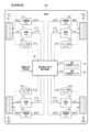
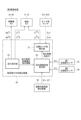
- FIG. 1 is a block diagram of a vehicle equipped with a vehicle travel direction detection device according to a first embodiment.
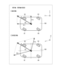
- FIG. 2A is a diagram showing diagonal movement in an independently steered vehicle;
- FIG. 2B is a diagram showing lateral movement in an independently steered vehicle;
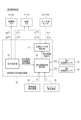
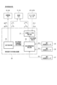
- FIG. 3 is a block diagram of a vehicle travel direction detection device according to a first embodiment;
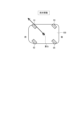
- FIG. 4 is a diagram for explaining acceleration that occurs when accelerating while traveling straight ahead and while traveling obliquely.
- FIG. 5 is a diagram showing the relationship between vehicle speed, X-axis acceleration, Y-axis acceleration, and diagonal movement angle.
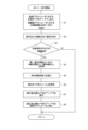
- FIG. 6 is a flowchart showing a process performed by the vehicle travel direction detection device.
- FIG. 7 is a block diagram of a vehicle travel direction detection device according to a second embodiment;
- FIG. 8 is a diagram illustrating lateral acceleration due to turning.
- FIG. 9 is a block diagram of a vehicle travel direction detection device according to a third embodiment.
- FIG. 10 is a block diagram of a vehicle travel direction detection device according to a fourth embodiment.
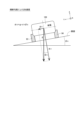
- FIG. 11 is a rear view of a vehicle illustrating the effect of a transverse gradient on acceleration;
- FIG. 12 is a side view of a vehicle illustrating the effect of a longitudinal gradient on acceleration;
- FIG. 13 is a diagram showing an arrangement of braking/driving actuators in another embodiment;
- FIG. 14 is a diagram showing an arrangement of braking/driving actuators in another embodiment;
- FIG. 15 is a diagram showing an example of setting the first axis and the second axis in another embodiment.
- the vehicle travel direction detection device of this embodiment is a device that detects the direction of diagonal movement relative to the front and rear axles of a vehicle in an independently steerable vehicle with three or more independently steerable tires, typically a four-wheel independently steerable vehicle.
- the configuration of an independently steered vehicle 100 equipped with a vehicle travel direction detection device 20 of the first embodiment will be described with reference to Fig. 1.
- the vehicle 100 shown in Fig. 1 has four tires 91-94, and each tire 91-94 can be steered independently and can be independently braked and driven.
- the left front wheel 91 is marked “FL”
- the right front wheel 92 is marked “FR”
- the left rear wheel 93 is marked “RL”
- the right rear wheel 94 is marked "RR”.
- the symbols of each element below and the suffixes "1" to "4" in each symbol correspond to the FL, FR, RL, and RR tires 91-94, respectively.
- the vehicle 100 is equipped with steering actuators 71-74, braking/driving actuators 81-84, and tire angle sensors 671-674 that detect the actual tire angles (hereinafter "actual tire angles") corresponding to each of the tires 91-94.
- actuator is written as “Act.”
- the tire angle is expressed as 0 at the neutral position parallel to the vehicle's longitudinal axis, with the counterclockwise direction being positive and the clockwise direction from the neutral position being negative.
- the steering actuators 71-74 are configured integrally with a motor section such as a three-phase brushless motor including a stator and rotor wound with windings, and a motor drive device that controls the drive current passed through the windings.
- a motor section such as a three-phase brushless motor including a stator and rotor wound with windings, and a motor drive device that controls the drive current passed through the windings.
- Each tire 91-94 can be steered independently by the steering torques Tst1-Tst4 output by the steering actuators 71-74.
- the braking/driving actuators 81-84 are configured as a set of an electric brake as a braking actuator and an in-wheel motor as a driving actuator. Acceleration occurs when the braking/driving forces of each tire 91-94 output by the braking/driving actuators 81-84 are transmitted to the road surface.
- acceleration includes positive acceleration during acceleration due to driving, as well as negative acceleration during deceleration due to braking.
- the tire angle sensors 671-674 may be configured with an encoder or the like that directly detects the actual tire angle. Alternatively, if there is a correlation between the drive current of the steering actuators 71-74 and the tire angle, the drive current of the steering actuators 71-74 detected by the current sensor may be converted to the detected tire angles ⁇ s1- ⁇ s4 based on the current-torque characteristics and the torque transmission coefficient. In that case, the current sensor is considered to function as the tire angle sensor 671-674.
- first axis and a “second axis” that intersect with each other on a plane parallel to the road surface.
- the X-axis which is the front-rear axis (vertical axis) of the vehicle 100
- the Y-axis which is the left-right axis (horizontal axis) of the vehicle 100
- the first axis and the second axis are perpendicular to each other.
- the vehicle 100 is equipped with a first acceleration sensor 35 that detects the X-axis acceleration ⁇ x, which is the “acceleration of the first axis,” and a second acceleration sensor 36 that detects the Y-axis acceleration ⁇ y, which is the “acceleration of the second axis.”
- a movement direction indication value by a steering wheel operation by a driver or a steering signal of an autonomous vehicle is input to vehicle movement direction detection device 20. Based on the movement direction indication value, vehicle movement direction detection device 20 indicates target tire angles ⁇ * 1- ⁇ * 4 for steering actuators 71-74 and target braking/driving forces BD * 1-BD * 4 for braking/driving actuators 81-84.
- the vehicle travel direction detection device 20 calculates the "diagonal movement angle," which is the angle of the travel direction relative to the front and rear axes of the vehicle 100, based on the two-axis accelerations ⁇ x and ⁇ y obtained from the acceleration sensors 35 and 36 when the vehicle 100 is driven or braked (i.e., when driving or braking).
- vehicle traveling direction detection device 20 acquires detected tire angles ⁇ s1- ⁇ s4 of each of tires 91-94 detected by tire angle sensors 671-674. Vehicle traveling direction detection device 20 corrects target tire angles ⁇ * 1- ⁇ * 4 from the oblique movement angle and detected tire angles ⁇ s1- ⁇ s4, and instructs steering actuators 71-74 of the corrected target tire angles ⁇ ** 1- ⁇ ** 4.
- diagonal movement as shown in FIG. 2A and lateral movement as shown in FIG. 2B are possible.
- all tires 91-94 are steered to the same tire angle with an absolute value of less than 90 degrees.
- lateral movement all tires 91-94 are steered to an absolute value of 90 degrees.
- diagonal movement is useful for changing driving lanes, and lateral movement is useful for parallel parking.
- the front side of the independently steering vehicle 100 is shown in a streamlined shape. The letters "front/rear" and "center of gravity" of the vehicle are only written in FIG. 2A and are omitted in subsequent figures.
- the purpose of this embodiment is to correctly detect the direction of diagonal movement relative to the vehicle's front and rear axes even when there is a detection error in the tire angle sensors 671-674 of the independently steered vehicle 100.
- the vehicle direction detection device 20 of this embodiment calculates the angle of diagonal movement based on the X-axis acceleration ⁇ x and Y-axis acceleration ⁇ y detected by the two-axis acceleration sensors 35, 36 when the vehicle 100 is accelerating or decelerating while braking or driving.
- the vehicle travel direction detection device 20 of the first embodiment has a driving instruction unit 25, a diagonal movement angle calculation unit 26, and, as an optional configuration, a target tire angle correction unit 27.
- the vehicle travel direction detection device 20 does not simply detect the direction of travel, but also includes a function of controlling vehicle travel based on the detected information.
- the basic configuration of the vehicle travel direction detection device 20 is the same as in the first embodiment, but it is mounted on a vehicle 100 further equipped with other additional devices, and processing using information obtained from the additional devices is added.
- driving instruction unit 25 instructs target tire angle ⁇ * 1- ⁇ * 4 for steering actuators 71-74 and target braking/driving force BD * 1-BD * 4 for braking/driving actuators 81-84.
- Driving instruction unit 25 also notifies driving angle and acceleration/deceleration instruction information to oblique movement angle calculation unit 26.
- Target tire angle ⁇ * 1- ⁇ * 4 is reflected in the driving angle instruction information
- target braking/driving force BD * 1-BD * 4 is reflected in the acceleration/deceleration instruction information.
- the diagonal movement angle calculation unit 26 recognizes that the vehicle 100 is being braked or driven based on acceleration/deceleration instruction information from the driving instruction unit 25.
- the diagonal movement angle calculation unit 26 acquires the X-axis acceleration ⁇ x from the first acceleration sensor 35 and the Y-axis acceleration ⁇ y from the second acceleration sensor 36.
- the diagonal movement angle calculation unit 26 calculates the diagonal movement angle ⁇ based on the acquired two-axis accelerations ⁇ x and ⁇ y.
- Vehicle acceleration ⁇ is the acceleration in the vehicle's forward direction on the XY plane that includes the X-axis and Y-axis.
- the forward direction of the X-axis is shown as positive.
- the acceleration when the acceleration of one of the first and second axes is in the vehicle travel direction, the acceleration may be calculated from the relationship between the vehicle drive torque and mass, or the time derivative of the wheel rotation speed.
- the vehicle acceleration ⁇ is calculated using equation (1.3), and the diagonal movement angle ⁇ is calculated using equation (1.4). Therefore, based on the two-axial accelerations ⁇ x and ⁇ y detected by the acceleration sensors 35 and 36, the diagonal movement angle ⁇ can be calculated, making it possible to determine whether the vehicle is traveling straight ahead or diagonally.
- the dashed line shows the CAE analysis results of vehicle speed V, X-axis acceleration ⁇ x, Y-axis acceleration ⁇ y, and diagonal movement angle ⁇ according to formula (1.4) when accelerating at a constant vehicle acceleration ⁇ while traveling diagonally
- the solid line shows the CAE analysis results of vehicle speed V, X-axis acceleration ⁇ x, Y-axis acceleration ⁇ y, and diagonal movement angle ⁇ according to formula (1.4) when traveling straight ahead, and when accelerating at a constant vehicle acceleration ⁇ while traveling diagonally.
- the vehicle acceleration ⁇ is commonly 1 [m/ s2 ]
- the traveling angle instruction value during diagonal traveling is 5 [deg].
- the X-axis acceleration ⁇ x When accelerating at a vehicle acceleration ⁇ of 1 [m/ s2 ] while traveling straight ahead, the X-axis acceleration ⁇ x is 1 [m/ s2 ] and the Y-axis acceleration ⁇ y is 0 [m/ s2 ].
- the X-axis acceleration ⁇ x when accelerating at a vehicle acceleration ⁇ of 1 [m/ s2 ] while traveling diagonally, the X-axis acceleration ⁇ x is 0.996 [m/ s2 ] and the Y-axis acceleration ⁇ y is 0.09 [m/ s2 ].
- the diagonal movement angle ⁇ calculated by equation (1.4) is equal to the traveling angle command value, 5 [deg].
- Target tire angle correction unit 27 stores the oblique movement angle ⁇ calculated by oblique movement angle calculation unit 26.
- Target tire angle correction unit 27 also acquires the detected tire angles ⁇ s1- ⁇ s4 of each tire 91-94 detected by tire angle sensors 671-674, and calculates the deviation (deviation) from the oblique movement angle ⁇ .
- Target tire angle correction unit 27 calculates corrected target tire angles ⁇ ** 1- ⁇ **4 by correcting the target tire angles ⁇ * 1- ⁇ * 4 of each tire 91-94 according to the deviation between the oblique movement angle ⁇ and the detected tire angles ⁇ s1- ⁇ s4 . Then, target tire angle correction unit 27 instructs steering actuators 71-74 of the corrected target tire angles ⁇ ** 1- ⁇ ** 4. In this way, the target tire angles ⁇ ** 1- ⁇ ** 4 are corrected by feedback control of the detected tire angles ⁇ s1- ⁇ s4.
- the flowchart in Figure 6 shows the processing performed by the vehicle travel direction detection device 20.
- the symbol "S" means a step. This processing is repeatedly performed while the vehicle 100 is traveling, from when it starts traveling until it stops.
- the driving instruction unit 25 instructs the target tire angle ⁇ * 1- ⁇ * 4 for the steering actuators 71-74 and the target braking/driving forces BD * 1-BD * 4 for the braking/driving actuators 81-84 based on the movement direction instruction value.
- the vehicle 100 travels in the instructed movement direction according to the operation of the steering actuators 71-74 and the braking/driving actuators 81-84.
- S3 it is determined whether an acceleration/deceleration command based on the target braking/driving force BD * 1-BD * 4 is being output from the driving command unit 25, that is, whether the vehicle is currently in the braking/driving state. If an acceleration/deceleration command is not being output and the vehicle is traveling at a constant speed, the answer in S3 is NO and the routine ends. If an acceleration command based on driving or a deceleration command based on braking is being output, the answer in S3 is YES and the routine proceeds to S4.
- the diagonal movement angle calculation unit 26 acquires the X-axis acceleration ⁇ x from the first acceleration sensor 35 and acquires the Y-axis acceleration ⁇ y from the second acceleration sensor 36. In S5, the diagonal movement angle calculation unit 26 calculates the diagonal movement angle ⁇ based on the acquired X-axis acceleration ⁇ x and Y-axis acceleration ⁇ y.
- target tire angle correcting unit 27 acquires detected tire angles ⁇ s1- ⁇ s4 of each of tires 91-94.
- target tire angle correcting unit 27 calculates corrected target tire angles ⁇ **1- ⁇ **4 by correcting target tire angles ⁇ * 1- ⁇ * 4 of each of tires 91-94 in accordance with the deviation between oblique movement angle ⁇ calculated by oblique movement angle calculation unit 26 and detected tire angles ⁇ s1- ⁇ s4 .
- target tire angle correcting unit 27 instructs steering actuators 71-74 of corrected target tire angles ⁇ ** 1 - ⁇ ** 4.
- the vehicle travel direction detection device 20 calculates the diagonal movement angle ⁇ using the two-axial accelerations ⁇ x, ⁇ y detected during braking and driving in the independently steered vehicle 100. For example, even if the detected tire angles ⁇ s1- ⁇ s4 are misaligned with the actual tire angles due to improper installation of the tire angle sensors 671-674, the travel direction of the diagonal movement can be detected. This makes it possible to determine whether the travel direction of the vehicle 100 is the intended direction.
- the vehicle 100 can be moved in the intended direction without mechanically adjusting the alignment of the steering actuators 71-74.
- the vehicle travel direction detection device 20 is mounted on a vehicle equipped with a vehicle speed detection device 40 that detects a vehicle speed V, and a yaw rate detection device 45 that detects a yaw rate ⁇ of the vehicle.
- the oblique movement angle calculation unit 26 corrects the X-axis acceleration ⁇ x and the Y-axis acceleration ⁇ y using the vehicle speed V obtained from the vehicle speed detection device 40 and the yaw rate ⁇ obtained from the yaw rate detection device 45. Specifically, mainly the Y-axis acceleration ⁇ y is corrected.
- tire angles ⁇ 1, ⁇ 2, and ⁇ 3 other than the right rear wheel 94 are steered equally to the right, and only tire angle ⁇ 4 of the right rear wheel 94 is steered excessively to the right.
- the vehicle 100 turns counterclockwise while moving diagonally. In this way, when some tire angles deviate from the average tire angle of the entire vehicle, a turn (yaw motion) occurs, and the acceleration ⁇ yaw caused by the turn causes an error in the diagonal movement angle ⁇ .
- the yaw rate ⁇ [rad/s] is expressed by equation (2.1) using the vehicle speed V [m/s] and the turning radius R [m].
- the acceleration ⁇ yaw [m/ s2 ] due to turning is expressed by equation (2.2) using the vehicle speed V [m/s] and the yaw rate ⁇ [rad/s].
- the generated acceleration ⁇ yaw is 0.49 [m/ s2 ].
- the acceleration ⁇ yaw due to turning is calculated using the vehicle speed V and yaw rate ⁇ , and the accelerations ⁇ x and ⁇ y detected by the acceleration sensors 35 and 36 are corrected to remove the acceleration error due to turning, thereby improving the accuracy of the diagonal movement angle ⁇ .
- the diagonal movement angle calculation unit 26 corrects the X-axis acceleration ⁇ x and the Y-axis acceleration ⁇ y using the road gradient angle. In other words, the accuracy of the diagonal movement angle ⁇ can be improved by correcting the accelerations ⁇ x and ⁇ y detected by the acceleration sensors 35 and 36 to remove the error in the acceleration caused by the road gradient.
- the third and fourth embodiments may be combined with the second embodiment in which the accelerations ⁇ x and ⁇ y are corrected using the vehicle speed V and the yaw rate ⁇ .
- the third and fourth embodiments differ in the way in which the diagonal movement angle calculation unit 26 acquires the road gradient angle.
- the vehicle travel direction detection device 20 is mounted on a vehicle equipped with a road gradient angle detection device 50 that detects the road gradient angle.
- the road gradient angle detection device 50 detects the road gradient angle using map information containing road surface gradient information and a coordinate detection sensor (GPS).
- GPS coordinate detection sensor
- Fig. 11 which shows the rear view of the vehicle
- the gradient angle in a cross section perpendicular to the longitudinal axis of the vehicle 100 is represented as the transverse gradient angle ⁇ s.
- the acceleration ⁇ s due to the transverse gradient is expressed by equation (3.1) using the gravitational acceleration g ( ⁇ 9.8 [m/ s2 ]).
- the acceleration ⁇ s due to the transverse gradient is 0.2 [m/ s2 ].
- the gradient angle in a cross section along the longitudinal axis of the vehicle 100 is represented as the longitudinal gradient angle ⁇ f.
- the acceleration ⁇ f due to the longitudinal gradient is expressed by equation (3.2) using the gravitational acceleration g.
- the longitudinal gradient angle ⁇ f is 6.84 [deg] (gradient 12%)
- the acceleration ⁇ f due to the longitudinal gradient is 1.17 [m/ s2 ].
- the diagonal movement angle calculation unit 26 uses the road gradient angles ⁇ s and ⁇ f obtained from the road gradient angle detection device 50 to correct the X-axis acceleration ⁇ x and the Y-axis acceleration ⁇ y so as to remove the acceleration error caused by the road gradient.
- the vehicle travel direction detection device 20 is mounted on a vehicle equipped with a third acceleration sensor 37 that detects acceleration on a third axis perpendicular to the road surface.
- the third axis is perpendicular to the first and second axes on a plane parallel to the road surface, i.e., the X-axis and Y-axis in this embodiment.
- the third axis is represented as the Z-axis
- the acceleration on the third axis is represented as the Z-axis acceleration ⁇ z.
- the diagonal movement angle calculation unit 26 corrects the X-axis acceleration ⁇ x and the Y-axis acceleration ⁇ y using the road gradient angles ⁇ s and ⁇ f estimated based on the Z-axis acceleration ⁇ z obtained from the third acceleration sensor 37.
- the braking/driving actuators may be any actuators that generate acceleration in the vehicle 100 by transmitting the braking/driving force output to each tire 91-94 to the road surface, and may not be provided individually for each tire 91-94. In other words, each tire 91-94 is independently steered, but does not have to be independently braked or driven.
- the independently steered vehicle 105 shown in FIG. 13 is equipped with a front wheel braking/driving actuator 85 that outputs a common braking/driving force to the left and right front tires 91, 92, and a rear wheel braking/driving actuator 86 that outputs a common braking/driving force to the left and right rear tires 93, 94.
- the independently steered vehicle 107 shown in FIG. 14 is equipped with a four-wheel braking/driving actuator 87 that outputs a common braking/driving force to all four tires 91-94.
- the main motor or engine corresponds to the four-wheel driving actuator
- the hydraulic generating device that distributes brake hydraulic pressure to the four wheels corresponds to the four-wheel braking actuator.
- the vehicle travel direction detection device 20 is similarly applied to these vehicles 105 and 107.
- target braking/driving forces BD * 1 and BD * 2 have the same value
- target braking/driving forces BD * 3 and BD * 4 have the same value
- target braking/driving forces BD * 1-BD * 4 have the same value.
- the brakes for braking and the motors for driving do not necessarily have to be provided as a set.
- four electric brakes for braking may be provided for each tire, and two motors for driving may be provided, one for the left and right front wheels and one for the left and right rear wheels.
- the "first and second axes intersecting each other on a plane parallel to the road surface" along which acceleration is detected by the acceleration detection device are not limited to the mutually orthogonal X-axis and Y-axis.
- the p-axis and q-axis which are non-orthogonal axes, may be set as the first and second axes.
- the phase of the vehicle acceleration ⁇ which is a resultant vector of the p-axis acceleration ⁇ p and the q-axis acceleration ⁇ q, is calculated as the diagonal movement angle ⁇ .
- the vehicle travel direction detection device 20 is shown as a higher-level control device for the steering actuators 71-74. This configuration is not limiting, and the vehicle travel direction detection device 20 and the drive devices for each of the steering actuators 71-74 may function as a single unit. For example, the drive devices for the four steering actuators 71-74 may communicate information with each other to cooperate and realize the function of the vehicle travel direction detection device 20.
- An independently steered vehicle equipped with the vehicle travel direction detection device 20 is not limited to a four-wheeled vehicle, but may be any "vehicle with three or more wheels that can be steered independently," including three-wheeled vehicles, six-wheeled vehicles, etc.
- Vehicles include vehicles that run on public roads following the steering wheel operation by a driver or the steering signal of an automatic driving device, as well as green slow mobility and AGVs (automated guided vehicles) that run at low speeds in specific areas.
- a vehicle travel direction detection device mounted on a vehicle equipped with a vehicle speed detection device (40) that detects the vehicle speed and a yaw rate detection device (45) that detects the yaw rate of the vehicle the diagonal movement angle calculation unit correcting the acceleration of the first axis and the second axis using the vehicle speed acquired from the vehicle speed detection device and the yaw rate acquired from the yaw rate detection device" corresponding to the second embodiment may be combined with the disclosure of "a vehicle travel direction detection device mounted on a vehicle equipped with a road gradient angle detection device (50) that detects a road gradient angle, the diagonal movement angle calculation unit correcting the acceleration of the first axis and the second axis using the road gradient angle ( ⁇ s, ⁇ f) acquired from the road gradient angle detection device" corresponding to the third embodiment.
- a vehicle travel direction detection device mounted on a vehicle equipped with a vehicle speed detection device (40) that detects the vehicle speed and a yaw rate detection device (45) that detects the yaw rate of the vehicle the diagonal movement angle calculation unit corrects the acceleration of the first axis and the second axis using the vehicle speed acquired from the vehicle speed detection device and the yaw rate acquired from the yaw rate detection device" corresponding to the second embodiment may be combined with the disclosure of "a vehicle travel direction detection device mounted on a vehicle equipped with a third acceleration sensor (37) that detects the acceleration of a third axis perpendicular to the road surface, the diagonal movement angle calculation unit corrects the acceleration of the first axis and the second axis using a road gradient angle ( ⁇ s, ⁇ f) estimated based on the acceleration of the third axis ( ⁇ z) acquired from the third acceleration sensor" corresponding to the fourth embodiment.
- a vehicle travel direction detection device mounted on a vehicle equipped with a third acceleration sensor (37) that detects the acceleration
- Each control unit (driving instruction unit, diagonal movement angle calculation unit, target tire angle correction unit) and its method described in this disclosure may be realized by a dedicated computer provided by configuring a processor and memory programmed to execute one or more functions embodied in a computer program.
- each control unit and its method described in this disclosure may be realized by a dedicated computer provided by configuring a processor with one or more dedicated hardware logic circuits.
- each control unit and its method described in this disclosure may be realized by one or more dedicated computers configured by combining a processor and memory programmed to execute one or more functions and a processor configured with one or more hardware logic circuits.
- the computer program may be stored in a computer-readable non-transient tangible recording medium as instructions executed by the computer.
Landscapes
- Engineering & Computer Science (AREA)
- Chemical & Material Sciences (AREA)
- Combustion & Propulsion (AREA)
- Transportation (AREA)
- Mechanical Engineering (AREA)
- Steering Control In Accordance With Driving Conditions (AREA)
Abstract
Dans un véhicule dans lequel chaque pneu peut être dirigé indépendamment, l'accélération est générée par la force de freinage/d'entraînement de chaque pneu, la force de freinage/entraînement étant délivrée par des actionneurs de freinage/entraînement (81-84). Un premier capteur d'accélération (35) et un second capteur d'accélération (36) détectent respectivement des accélérations sur un premier axe et un second axe, qui se croisent dans un plan parallèle à la surface de route. Une unité d'instruction de déplacement (25) d'un dispositif de détection de direction de déplacement de véhicule (20) indique des angles de pneu cibles (δ*1-δ*4) pour des actionneurs de direction (71-74) et des forces de freinage/entraînement cibles (BD*1-BD*4) pour les actionneurs de freinage/entraînement (81-84). Pendant le freinage/l'entraînement du véhicule, une unité de calcul d'angle de mouvement oblique (26) calcule un angle de mouvement oblique (θ), qui est l'angle de la direction de déplacement par rapport à l'axe avant-arrière du véhicule, sur la base de l'accélération de premier axe (αx) acquise à partir du premier capteur d'accélération (35) et de l'accélération de second axe (αy) acquise à partir du second capteur d'accélération (36).
Applications Claiming Priority (2)
| Application Number | Priority Date | Filing Date | Title |
|---|---|---|---|
| JP2023-092540 | 2023-06-05 | ||
| JP2023092540A JP2024174624A (ja) | 2023-06-05 | 2023-06-05 | 車両進行方向検出装置 |
Publications (1)
| Publication Number | Publication Date |
|---|---|
| WO2024253062A1 true WO2024253062A1 (fr) | 2024-12-12 |
Family
ID=93795996
Family Applications (1)
| Application Number | Title | Priority Date | Filing Date |
|---|---|---|---|
| PCT/JP2024/020213 Ceased WO2024253062A1 (fr) | 2023-06-05 | 2024-06-03 | Dispositif de détection de direction de déplacement de véhicule |
Country Status (2)
| Country | Link |
|---|---|
| JP (1) | JP2024174624A (fr) |
| WO (1) | WO2024253062A1 (fr) |
Citations (6)
| Publication number | Priority date | Publication date | Assignee | Title |
|---|---|---|---|---|
| JPH0357771A (ja) * | 1989-07-25 | 1991-03-13 | Kayaba Ind Co Ltd | 電動式独立型後輪転舵装置 |
| JP2007223390A (ja) * | 2006-02-22 | 2007-09-06 | Nissan Motor Co Ltd | 車両の挙動制御装置 |
| JP2019171910A (ja) * | 2018-03-27 | 2019-10-10 | Ntn株式会社 | ステアリングシステムおよびこれを備えた車両 |
| JP2021146977A (ja) * | 2020-03-23 | 2021-09-27 | 株式会社Soken | 自動車用転舵装置 |
| JP2022088025A (ja) * | 2020-12-02 | 2022-06-14 | 株式会社Soken | 車両走行制御装置 |
| JP2022129228A (ja) * | 2021-02-24 | 2022-09-05 | トヨタ自動車株式会社 | 車両制御方法、車両制御システム、及び車両 |
-
2023
- 2023-06-05 JP JP2023092540A patent/JP2024174624A/ja active Pending
-
2024
- 2024-06-03 WO PCT/JP2024/020213 patent/WO2024253062A1/fr not_active Ceased
Patent Citations (6)
| Publication number | Priority date | Publication date | Assignee | Title |
|---|---|---|---|---|
| JPH0357771A (ja) * | 1989-07-25 | 1991-03-13 | Kayaba Ind Co Ltd | 電動式独立型後輪転舵装置 |
| JP2007223390A (ja) * | 2006-02-22 | 2007-09-06 | Nissan Motor Co Ltd | 車両の挙動制御装置 |
| JP2019171910A (ja) * | 2018-03-27 | 2019-10-10 | Ntn株式会社 | ステアリングシステムおよびこれを備えた車両 |
| JP2021146977A (ja) * | 2020-03-23 | 2021-09-27 | 株式会社Soken | 自動車用転舵装置 |
| JP2022088025A (ja) * | 2020-12-02 | 2022-06-14 | 株式会社Soken | 車両走行制御装置 |
| JP2022129228A (ja) * | 2021-02-24 | 2022-09-05 | トヨタ自動車株式会社 | 車両制御方法、車両制御システム、及び車両 |
Also Published As
| Publication number | Publication date |
|---|---|
| JP2024174624A (ja) | 2024-12-17 |
Similar Documents
| Publication | Publication Date | Title |
|---|---|---|
| JP4568302B2 (ja) | 加加速度情報を用いた車両の前後加速度制御装置 | |
| KR101734277B1 (ko) | 인휠 시스템을 이용한 차량 제어 방법 | |
| JP5830554B2 (ja) | 四輪操舵車両の制御方法 | |
| CN107848526B (zh) | 车辆转弯控制装置 | |
| JP2021503402A (ja) | 車両のステアリングシステムを制御する方法 | |
| CN110271608A (zh) | 车辆转向控制方法、装置、系统以及车辆 | |
| WO2019188951A1 (fr) | Dispositif de commande, dispositif de direction, procédé de commande et programme | |
| JP6600850B2 (ja) | 車両制御装置及び車両制御方法 | |
| US9956891B2 (en) | Electric vehicle | |
| US20230398880A1 (en) | Motion control device for left and right independent drive vehicle | |
| JP5559833B2 (ja) | 加加速度情報を用いた車両の運動制御装置および方法 | |
| JP5911482B2 (ja) | 操舵角を電気機械的に調整するための方法および電気機械式ステアリングを備えた自動車 | |
| JP5347500B2 (ja) | 車両制御装置及び車両制御方法 | |
| JPH04266538A (ja) | 車両運動特性補正装置 | |
| JP5045108B2 (ja) | 走行支援装置 | |
| US20250100617A1 (en) | Vehicle steering system | |
| JP2024174624A (ja) | 車両進行方向検出装置 | |
| JP4349204B2 (ja) | 左右独立駆動式車両 | |
| JP5071154B2 (ja) | 車両の走行姿勢制御装置及び走行姿勢制御方法 | |
| KR102614555B1 (ko) | 자율 주행 차량 및 이의 조향 제어 방법 | |
| JP2006182050A (ja) | 4輪独立駆動車の制駆動力制御装置 | |
| JP2013198174A (ja) | 車両の駆動力制御装置 | |
| JP2024177863A (ja) | 制駆動力制御装置 | |
| JP2021195096A (ja) | 転舵制御装置 | |
| JP2022106255A (ja) | 車両の前後輪転舵角制御装置 |
Legal Events
| Date | Code | Title | Description |
|---|---|---|---|
| 121 | Ep: the epo has been informed by wipo that ep was designated in this application |
Ref document number: 24819292 Country of ref document: EP Kind code of ref document: A1 |
|
| NENP | Non-entry into the national phase |
Ref country code: DE |
|
| 122 | Ep: pct application non-entry in european phase |
Ref document number: 24819292 Country of ref document: EP Kind code of ref document: A1 |