WO2024253087A1 - Propulsion system, propulsion control device, and propulsion control program - Google Patents
Propulsion system, propulsion control device, and propulsion control program Download PDFInfo
- Publication number
- WO2024253087A1 WO2024253087A1 PCT/JP2024/020358 JP2024020358W WO2024253087A1 WO 2024253087 A1 WO2024253087 A1 WO 2024253087A1 JP 2024020358 W JP2024020358 W JP 2024020358W WO 2024253087 A1 WO2024253087 A1 WO 2024253087A1
- Authority
- WO
- WIPO (PCT)
- Prior art keywords
- motor
- demagnetization
- temperature
- control device
- flight control
- Prior art date
- Legal status (The legal status is an assumption and is not a legal conclusion. Google has not performed a legal analysis and makes no representation as to the accuracy of the status listed.)
- Ceased
Links
Images


Classifications
-
- B—PERFORMING OPERATIONS; TRANSPORTING
- B64—AIRCRAFT; AVIATION; COSMONAUTICS
- B64D—EQUIPMENT FOR FITTING IN OR TO AIRCRAFT; FLIGHT SUITS; PARACHUTES; ARRANGEMENT OR MOUNTING OF POWER PLANTS OR PROPULSION TRANSMISSIONS IN AIRCRAFT
- B64D33/00—Arrangement in aircraft of power plant parts or auxiliaries not otherwise provided for
- B64D33/08—Arrangement in aircraft of power plant parts or auxiliaries not otherwise provided for of power plant cooling systems
-
- B—PERFORMING OPERATIONS; TRANSPORTING
- B64—AIRCRAFT; AVIATION; COSMONAUTICS
- B64D—EQUIPMENT FOR FITTING IN OR TO AIRCRAFT; FLIGHT SUITS; PARACHUTES; ARRANGEMENT OR MOUNTING OF POWER PLANTS OR PROPULSION TRANSMISSIONS IN AIRCRAFT
- B64D27/00—Arrangement or mounting of power plants in aircraft; Aircraft characterised by the type or position of power plants
- B64D27/02—Aircraft characterised by the type or position of power plants
- B64D27/24—Aircraft characterised by the type or position of power plants using steam or spring force
-
- B—PERFORMING OPERATIONS; TRANSPORTING
- B64—AIRCRAFT; AVIATION; COSMONAUTICS
- B64D—EQUIPMENT FOR FITTING IN OR TO AIRCRAFT; FLIGHT SUITS; PARACHUTES; ARRANGEMENT OR MOUNTING OF POWER PLANTS OR PROPULSION TRANSMISSIONS IN AIRCRAFT
- B64D27/00—Arrangement or mounting of power plants in aircraft; Aircraft characterised by the type or position of power plants
- B64D27/02—Aircraft characterised by the type or position of power plants
- B64D27/30—Aircraft characterised by electric power plants
- B64D27/31—Aircraft characterised by electric power plants within, or attached to, wings
-
- B—PERFORMING OPERATIONS; TRANSPORTING
- B64—AIRCRAFT; AVIATION; COSMONAUTICS
- B64D—EQUIPMENT FOR FITTING IN OR TO AIRCRAFT; FLIGHT SUITS; PARACHUTES; ARRANGEMENT OR MOUNTING OF POWER PLANTS OR PROPULSION TRANSMISSIONS IN AIRCRAFT
- B64D27/00—Arrangement or mounting of power plants in aircraft; Aircraft characterised by the type or position of power plants
- B64D27/02—Aircraft characterised by the type or position of power plants
- B64D27/30—Aircraft characterised by electric power plants
- B64D27/34—All-electric aircraft
-
- B—PERFORMING OPERATIONS; TRANSPORTING
- B64—AIRCRAFT; AVIATION; COSMONAUTICS
- B64D—EQUIPMENT FOR FITTING IN OR TO AIRCRAFT; FLIGHT SUITS; PARACHUTES; ARRANGEMENT OR MOUNTING OF POWER PLANTS OR PROPULSION TRANSMISSIONS IN AIRCRAFT
- B64D31/00—Power plant control systems; Arrangement of power plant control systems in aircraft
- B64D31/16—Power plant control systems; Arrangement of power plant control systems in aircraft for electric power plants
-
- H—ELECTRICITY
- H02—GENERATION; CONVERSION OR DISTRIBUTION OF ELECTRIC POWER
- H02P—CONTROL OR REGULATION OF ELECTRIC MOTORS, ELECTRIC GENERATORS OR DYNAMO-ELECTRIC CONVERTERS; CONTROLLING TRANSFORMERS, REACTORS OR CHOKE COILS
- H02P29/00—Arrangements for regulating or controlling electric motors, appropriate for both AC and DC motors
- H02P29/02—Providing protection against overload without automatic interruption of supply
- H02P29/024—Detecting a fault condition, e.g. short circuit, locked rotor, open circuit or loss of load
- H02P29/028—Detecting a fault condition, e.g. short circuit, locked rotor, open circuit or loss of load the motor continuing operation despite the fault condition, e.g. eliminating, compensating for or remedying the fault
-
- H—ELECTRICITY
- H02—GENERATION; CONVERSION OR DISTRIBUTION OF ELECTRIC POWER
- H02P—CONTROL OR REGULATION OF ELECTRIC MOTORS, ELECTRIC GENERATORS OR DYNAMO-ELECTRIC CONVERTERS; CONTROLLING TRANSFORMERS, REACTORS OR CHOKE COILS
- H02P29/00—Arrangements for regulating or controlling electric motors, appropriate for both AC and DC motors
- H02P29/60—Controlling or determining the temperature of the motor or of the drive
- H02P29/62—Controlling or determining the temperature of the motor or of the drive for raising the temperature of the motor
-
- H—ELECTRICITY
- H02—GENERATION; CONVERSION OR DISTRIBUTION OF ELECTRIC POWER
- H02P—CONTROL OR REGULATION OF ELECTRIC MOTORS, ELECTRIC GENERATORS OR DYNAMO-ELECTRIC CONVERTERS; CONTROLLING TRANSFORMERS, REACTORS OR CHOKE COILS
- H02P29/00—Arrangements for regulating or controlling electric motors, appropriate for both AC and DC motors
- H02P29/60—Controlling or determining the temperature of the motor or of the drive
- H02P29/66—Controlling or determining the temperature of the rotor
- H02P29/662—Controlling or determining the temperature of the rotor the rotor having permanent magnets
Definitions
- the disclosure in this specification relates to a propulsion system, a propulsion control device, and a propulsion control program.
- Patent document 1 describes a motor system having a motor. In this motor system, if the motor temperature exceeds a reference temperature, it is determined that an abnormality in the motor temperature has occurred, and the motor output is reduced. Patent document 1 claims that it is possible to prevent the condition of a motor in which an abnormality in the motor temperature has occurred from worsening further.
- the main objective of this disclosure is to provide a propulsion system, a propulsion control device, and a propulsion control program that can improve the safety of a moving body.
- the disclosed embodiment comprises: A propulsion system for propelling a moving object, comprising: A motor having a permanent magnet and driven to propel the moving body; an information acquisition unit that acquires drive information indicating a drive state of the motor; a demagnetization management unit that manages the demagnetization of the permanent magnet using the drive information acquired by the information acquisition unit; It is a propulsion system equipped with.
- the demagnetization of the permanent magnets is managed using motor drive information.
- it is possible to drive the motor so that demagnetization of the permanent magnets is less likely to occur. This makes it possible to prevent demagnetization of the permanent magnets from occurring at all.
- This configuration also makes it possible to take measures against abnormalities, such as reducing the load on the permanent magnets, before the demagnetization of the permanent magnets progresses to the point where a motor abnormality occurs. This makes it possible to prevent the safety of the moving body from decreasing due to the progression of demagnetization of the permanent magnets. As described above, the safety of the moving body can be increased by managing the demagnetization of the permanent magnets.
- the disclosed aspect comprises: A propulsion control device for controlling a propulsion system having a motor that drives a moving body to propel the moving body, an information acquisition unit that acquires drive information indicating a drive state of the motor; a demagnetization management unit that manages demagnetization of a permanent magnet of the motor using the drive information acquired by the information acquisition unit; A propulsion control device equipped with the above.
- the above propulsion control device can improve the safety of the moving body, just like the above propulsion system.
- the disclosed aspect comprises: A propulsion control program for causing at least one processor to execute control of a propulsion system having a motor that drives a moving object to propel the moving object, A process of acquiring driving information indicating a driving state of a motor; A process of managing demagnetization of a permanent magnet of the motor using the drive information; A propulsion control program for causing at least one processor to execute the above.
- the above propulsion control program can improve the safety of a moving body, just like the above propulsion system.
- the above propulsion control device can achieve the same effects as the above propulsion system.
- FIG. 2 is a diagram showing the configuration of an eVTOL according to the first embodiment.
- FIG. 2 is a block diagram showing the electrical configuration of the propulsion system.
- FIG. 4 is a diagram for explaining a demagnetization region. 4 is a flowchart showing a procedure for flight control processing.
- 11 is a flowchart showing a procedure for a demagnetization response process.
- 10 is a flowchart showing the procedure of a second restricted range process.
- 11 is a flowchart showing the procedure of a restriction handling process.
- 11 is a flowchart showing a procedure of a maintenance process.
- 10 is a flowchart showing a procedure of a demagnetization response process in a second embodiment.
- FIG. 13 is a diagram for explaining the amount of deviation.
- FIG. 13 is a flowchart showing the procedure of a flight control process in a third embodiment.
- FIG. 4 is a diagram for explaining a demagnetization region.
- 13 is a flowchart showing the procedure of a flight control process in the fourth embodiment.
- 11 is a flowchart showing a procedure for a demagnetization response process.
- FIG. 13 is a block diagram showing the electrical configuration of a propulsion system according to a fifth embodiment.
- 4 is a flowchart showing a procedure for flight control processing.
- 4 is a flowchart showing the procedure for landing response processing.
- 5A and 5B are diagrams for explaining a first cooling threshold and a first stop threshold.
- 11 is a flowchart showing the procedure of a drive inspection process.
- 4 is a flowchart showing a procedure for takeoff preparation processing.
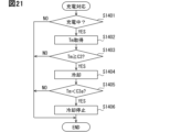
- 10 is a flowchart showing a procedure of a charging process.
- the propulsion system 30 shown in FIG. 1 is mounted on the eVTOL 10.
- the eVTOL 10 is an electric vertical take-off and landing aircraft.
- the electric vertical take-off and landing aircraft is an electric vertical take-off and landing aircraft, and is capable of vertical take-off and landing.
- eVTOL is an abbreviation for electric Vertical Take-Off and Landing aircraft.
- the eVTOL 10 is an electric flying object that flies in the atmosphere, and may be referred to as an electric flying object.
- the eVTOL 10 is also an electric aircraft, and may be referred to as an electric aircraft.
- the eVTOL 10 is a manned flying object with a crew member on board.
- the crew member of the eVTOL 10 includes a pilot as a pilot or a driver.
- the propulsion system 30 is a system that drives the eVTOL 10 to propel it.
- the propulsion system 30 may be referred to as a flight system.
- the eVTOL 10 has an airframe 11 and a propeller 20.
- the airframe 11 has an airframe body 12 and wings 13.
- the airframe body 12 is the fuselage of the airframe 11 and has a shape that extends, for example, from front to back.
- the airframe body 12 has a passenger compartment 14 for passengers to ride in.
- the wings 13 extend from the airframe body 12 and multiple wings 13 are provided on the airframe body 12.
- the wings 13 are fixed wings.
- the multiple wings 13 include a main wing, a tail, etc.
- the eVTOL 10 has a cabin.
- the cabin is provided inside the eVTOL 10.
- the cabin is the internal space of the aircraft body 12, and is formed by the aircraft body 12.
- the cabin can be the crew compartment 14 or a cargo bay.
- the crew compartment 14 can be a passenger cabin or a pilot compartment.
- the crew compartment 14 is provided with seats for the crew to sit in.
- the crew compartment 14 does not have to have any crew on board, and may house cargo.
- the eVTOL 10 is a multicopter having at least three propellers 20.
- at least six propellers 20 are provided on the airframe 11.
- the propellers 20 are provided on each of the airframe body 12 and the wings 13.
- the propellers 20 rotate around a propeller axis.
- the propeller axis is, for example, the center line of the propeller 20.
- the propellers 20 are capable of generating thrust and lift for the eVTOL 10.
- the propellers 20 are sometimes referred to as rotors or rotating wings.
- propeller output includes the rotation speed and torque of the propellers 20.
- the propeller 20 has blades, a boss, and a propeller shaft.
- the blades are arranged in multiple rows circumferentially around the propeller axis.
- the boss connects the multiple blades.
- the propeller shaft is the rotation axis of the propeller 20, and extends from the boss along the propeller axis.
- Flight modes of the eVTOL 10 include vertical takeoff, vertical landing, cruise, hovering, etc. Flight modes are sometimes referred to as flight modes.
- vertical takeoff the eVTOL 10 can take off without running.
- vertical takeoff the eVTOL 10 can rise vertically or rise diagonally upward.
- vertical landing the eVTOL 10 can land without running.
- vertical landing the eVTOL 10 can descend vertically or descend diagonally downward.
- Cruise is sometimes referred to as horizontal flight.
- the eVTOL 10 may fly horizontally without moving vertically, or may fly horizontally while moving vertically. Hovering is sometimes referred to as stationary flight.
- hovering the eVTOL 10 may fly as if stopped at a predetermined position in the air, or the eVTOL 10 may deviate vertically or horizontally from the predetermined position.
- the flight modes of the eVTOL 10 include lift.
- the eVTOL 10 moves in an up and down direction.
- the eVTOL 10 may rise diagonally upward or descend diagonally downward.
- the eVTOL 10 takes off vertically by lifting upward.
- the eVTOL 10 lands vertically by lifting downward.
- the eVTOL 10 is a tilt rotor aircraft.
- the tilt angle of the propeller 20 is adjustable.
- one propeller 20 can function as both a lift propeller and a cruise propeller.
- the tilt angle is adjusted so that the propeller 20 functions as a lift rotor.
- the tilt angle is adjusted so that the propeller 20 functions as a cruise rotor.
- the eVTOL 10 does not have to be a tilt rotor aircraft.
- the eVTOL 10 may have a separate lift propeller 20 and a separate cruise propeller 20.
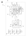
- the eVTOL 10 has a battery 31, a distributor 32, a communication unit 34, a flight control device 40, and an EPU 50.
- the battery 31, the distributor 32, the communication unit 34, the flight control device 40, and the EPU 50 are included in the propulsion system 30. Note that it is sufficient that the propulsion system 30 includes at least the flight control device 40 and the EPU 50.
- the flight control device 40 is sometimes referred to as a flight controller.
- the battery 31 is connected to the EPU 50 so that it can be electrically connected to it.
- the battery 31 is a power supply unit that supplies power to the EPU 50, and corresponds to a power supply unit.
- the battery 31 is a DC voltage source that applies a DC voltage to the EPU 50.
- the battery 31 has a secondary battery that can be charged and discharged. Examples of this secondary battery include a lithium ion battery and a nickel-metal hydride battery.
- the battery 31 is capable of storing power, and corresponds to a power storage device. Note that a fuel cell, a generator, or the like may be used as the power supply unit in addition to or instead of the battery 31.
- the distributor 32 is electrically connected to the battery 31 and the multiple EPUs 50.
- the distributor 32 distributes power from the battery 31 to the multiple EPUs 50.
- the battery 31 is electrically connected to the multiple EPUs 50 via the distributor 32.
- the battery 31 supplies power to the EPUs 50 via the distributor 32.
- the communication unit 34 is a communication device capable of wireless communication with an external device.
- the external device is a device located away from the eVTOL 10. Examples of external devices include communication devices installed in external facilities on the ground and communication devices installed in other flying objects. Examples of external facilities include a control center and a management center.
- the communication unit 34 is capable of communication with the flight control device 40.
- the communication unit 34 is connected to the flight control device 40 so that it can communicate via wired communication.
- the communication unit 34 may also be capable of wireless communication with the flight control device 40.
- the EPU 50 is a device that drives the propeller 20 to rotate, and corresponds to a drive device.
- EPU is an abbreviation for Electric Propulsion Unit.
- the EPU 50 is sometimes referred to as an electric drive device or an electric drive system.
- An EPU 50 is provided individually for each of the multiple propellers 20.
- the EPUs 50 are arranged on the propellers 20 along the propeller axis. All of the multiple EPUs 50 are fixed to the aircraft 11.
- the EPU 50 supports the propeller 20 so that it can rotate.
- the EPU 50 is connected to the propeller 20.
- the propeller 20 is fixed to the aircraft 11 via the EPU 50.
- the eVTOL 10 has a propulsion device 100.
- the propulsion device 100 is formed to include a propeller 20 and an EPU 50.
- the propulsion device 100 is a device for propelling the eVTOL 10.
- the propulsion device 100 causes the eVTOL 10 to fly by rotating the propeller 20.
- the eVTOL 10 is also a moving body that moves by the propulsion device 100.
- a plurality of propulsion devices 100 are provided in the eVTOL 10.
- One propulsion device 100 includes one each of a propeller 20 and an EPU 50 for driving the propeller 20. Of the propeller 20 and the EPU 50, only the EPU 50 may be referred to as the propulsion device 100.
- the EPU 50 has a motor device 60 and an inverter device 80.
- the motor device 60 has a motor 61 and a motor housing 70.
- the motor housing 70 is a housing and houses the motor 61.
- the motor 61 is a multi-phase AC motor.
- the motor 61 is a multi-phase AC rotating electric machine.
- the motor 61 is the flight drive source for the eVTOL 10 and functions as an electric motor.
- the motor 61 drives and rotates the propeller 20, enabling the eVTOL 10 to fly.
- the motor 61 is a flight motor for flying the eVTOL 10.
- the EPU 50 drives and rotates the propeller 20 by driving the motor 61.
- a brushless motor for example, is used as the motor 61.
- the motor 61 has a motor stator 62 and a motor rotor 63.
- the motor 61 has a motor stator 62.
- the motor stator 62 is a stator and is fixed to a motor housing 70.
- the motor rotor 63 rotates relative to the motor stator 62.
- the motor 61 is, for example, an axial gap type motor. In the motor 61, the motor stator 62 and the motor rotor 63 are aligned in the axial direction.
- the motor 61 has a motor shaft that rotates together with the motor rotor 63.
- the motor shaft is rotatably supported by the motor housing 70 or the like.
- the motor 61 is driven by supplying power to the motor stator 62.
- the motor stator 62 has a stator coil 62a.
- the stator coil 62a is a multi-phase coil.
- the stator coil 62a forms an armature.
- a current flows through the stator coil 62a, causing the motor rotor 63 to rotate.
- the motor rotor 63 has a rotor magnet 63a.
- the rotor magnet 63a forms a magnetic field.
- the rotor magnet 63a is a permanent magnet.
- the rotor magnet 63a is made of a rare earth magnet, a ferrite magnet, or the like.
- the rotor magnet 63a is made of a neodymium magnet.
- Thermal demagnetization can occur in the rotor magnet 63a. The higher the temperature of the rotor magnet 63a, the more likely the magnetic force of the rotor magnet 63a is to decrease due to thermal demagnetization.
- Reversible demagnetization and irreversible demagnetization can occur due to thermal demagnetization of the rotor magnet 63a.
- thermal demagnetization the magnetic force of the rotor magnet 63a decreases due to heat.
- reversible demagnetization occurs in the rotor magnet 63a due to thermal demagnetization, the higher the temperature of the rotor magnet 63a, the greater the amount of demagnetization due to reversible demagnetization.
- the motor output changes according to the magnetic force of the rotor magnet 63a.
- the motor output is a parameter that indicates the output of the motor 61.
- the motor output is the output torque of the motor 61.
- the output torque is the motor torque for rotating the motor rotor 63.
- the motor output is likely to decrease when the magnetic force of the rotor magnet 63a decreases.
- the motor output is likely to decrease as the irreversible demagnetization of the rotor magnet 63a progresses.
- the progression of irreversible demagnetization is sometimes referred to as the progression of deterioration.
- the motor device 60 is an air-cooled device.
- the motor device 60 has motor fins.
- the motor fins release heat from the motor device 60 to the outside air.
- the motor fins are heat dissipation fins and are included in the motor housing 70.
- the motor fins are provided on the outer surface of the motor housing 70.
- the inverter device 80 drives the motor device 60 by supplying power to the motor device 60.
- the inverter device 80 is a drive unit for driving the motor 61, and corresponds to a motor drive unit.
- the inverter device 80 has an inverter circuit 85 and an inverter housing 90.
- the inverter housing 90 is a housing and contains the inverter circuit 85.
- the inverter circuit 85 converts the power supplied to the motor 61.
- the inverter circuit 85 is sometimes referred to as an inverter, power conversion unit, or control circuit.
- the inverter circuit 85 performs power conversion for each of the multiple phases.
- the motor 61 drives according to the voltage and current supplied from the inverter circuit 85.
- the inverter device 80 is an air-cooled device.
- the inverter device 80 has inverter fins.
- the inverter fins release heat from the inverter device 80 to the outside air.
- the inverter fins are heat dissipation fins and are included in the inverter housing 90.
- the inverter fins are provided on the outer surface of the inverter housing 90.
- the propulsion device 100 is an air-cooled device.
- air cooling is possible using motor fins and inverter fins.
- a gas such as external air may flow into the interior of the propulsion device 100.
- the gas may pass through the interior of the motor housing 70 or the interior of the inverter housing 90.
- a gas such as air.
- the inverter device 80 has an inverter control unit 81.
- the inverter control unit 81 performs motor control via the inverter circuit 85.
- the motor control is control for driving the motor 61.
- the inverter control unit 81 also performs propulsion control.
- the propulsion control is control for driving the propulsion device 100.
- the propulsion control includes motor control.
- the propulsion control is also control for controlling the EPU 50, and is sometimes referred to as EPU control.
- the inverter control unit 81 has, for example, an ECU. ECU is an abbreviation for Electronic Control Unit.
- the inverter control unit 81 has a processor 82, a memory 83, and a program 84.
- the inverter control unit 81 is mainly composed of a computer. This computer has the processor 82, memory 83, an input/output interface, a bus connecting these, etc.
- the memory 83 stores the program 84.
- the program 84 is a program for performing propulsion control.
- the program 84 corresponds to a propulsion control program.
- the processor 82 is hardware for arithmetic processing coupled to the memory 83.
- the processor 82 executes various processes by accessing the memory 83.
- the memory 83 is a storage medium that stores a control program and the like.
- the memory 83 is a non-transitory tangible storage medium that non-temporarily stores computer-readable programs and data.
- the non-transitory tangible storage medium is a non-transitory tangible storage medium, and is realized by a semiconductor memory or a magnetic disk, for example.
- the program 84 includes computer-readable instructions that cause the processor 82 to execute various functions.
- the processor 82 is a processing unit that executes predetermined processes by executing instructions included in the program 84.
- the inverter control unit 81 controls the motor according to the required output.
- the required output is the motor output required of the inverter control unit 81.
- the required output includes the required torque required for the output torque.
- the required output is included in the command signal output by the flight control device 40 to the inverter control unit 81.
- the inverter control unit 81 adjusts the motor output according to the required output.
- the required output and the required torque are sometimes referred to as the target output and the target torque. Note that the motor output may be expressed as torque, current, voltage, motor rotation speed, etc.
- the inverter control unit 81 controls the motor using command signals from the flight control device 40 and detection signals from various sensors.
- the various sensors are communicatively connected to the inverter control unit 81.
- the various sensors include a motor sensor, a battery sensor, and an inverter sensor.
- the battery sensor is a temperature sensor or the like provided in the battery 31.
- the inverter sensor is a temperature sensor or the like provided in the inverter device 80.
- the motor sensors include a temperature sensor 65 and a current sensor 66.
- the temperature sensor 65 is provided in the motor device 60.
- the temperature sensor 65 detects the temperature of the motor 61.
- the temperature of the motor 61 includes the temperature of the rotor magnet 63a and the temperature of the stator coil 62a.
- the temperature sensor 65 can detect at least the temperature of the rotor magnet 63a.
- the temperature sensor 65 outputs a detection signal according to the temperature of the rotor magnet 63a.
- the temperature sensor 65 outputs a detection signal to the inverter control unit 81.
- the temperature sensor 65 may detect the temperature of the motor device 60, such as the motor housing 70.
- the current sensor 66 is provided in the motor device 60.
- the current sensor 66 detects the current flowing through the motor 61.
- the current sensor 66 detects the current flowing through the stator coil 62a.
- the current sensor 66 outputs a detection signal corresponding to the current flowing through the stator coil 62a.
- the current sensor 66 outputs the detection signal to the inverter control unit 81.
- the flight control device 40 is connected to the inverter control unit 81 so that they can communicate with each other.
- the flight control device 40 and the inverter control unit 81 may be capable of wireless communication.
- the flight control device 40 performs overall control to coordinate the drive of the multiple propulsion devices 100.
- the overall control coordinates the propulsion control performed by each of the multiple inverter control units 81.
- the flight control device 40 performs flight control.
- Flight control is control for flying the eVTOL 10.
- the flight control device 40 controls the propulsion system 30 and the EPU 50.
- Flight control is also control for propelling the eVTOL 10, and is sometimes referred to as propulsion control.
- the flight control device 40 corresponds to a propulsion control device.
- the flight control device 40 has, for example, an ECU.
- the flight control device 40 has a processor 42, a memory 43, and a program 44.
- the flight control device 40 is mainly composed of a computer. This computer has a processor 42, a memory 43, an input/output interface, a bus connecting these, etc.
- the memory 43 stores a program 44.
- the program 44 is a program for performing flight control.
- Processor 42 is hardware for arithmetic processing coupled to memory 43. Processor 42 executes various processes by accessing memory 43.
- Memory 43 is a storage medium that stores control programs and the like.
- Memory 43 is a non-transient tangible storage medium that non-temporarily stores computer-readable programs and data.
- Program 44 includes computer-readable instructions that cause processor 42 to execute various functions.
- Processor 42 is a processing unit that executes predetermined processes by executing instructions included in program 44.
- the flight control device 40 outputs information required for propulsion control to the inverter control unit 81.
- the flight control device 40 is a higher-level ECU for the inverter control unit 81.
- the flight control device 40 controls the multiple propulsion devices 100 individually according to the flight mode of the eVTOL 10, etc.
- the flight control device 40 can adjust the output of the propulsion devices 100 individually for each propulsion device 100.
- the flight control device 40 outputs a required output for each of the multiple propulsion devices 100.
- the required output is the output required of the propulsion device 100.
- the required output includes a required torque required for the motor 61. Note that the required output may be torque, current, voltage, propeller speed, etc.
- the flight control device 40 performs flight control according to the flight state of the eVTOL 10 and detection signals from various sensors.
- the flight state of the eVTOL 10 includes the flight mode and the flight attitude of the eVTOL 10.
- the various sensors are communicatively connected to the flight control device 40.
- the temperature sensor 65 and the current sensor 66 as various sensors are communicatively connected to both the inverter control unit 81 and the flight control device 40.
- the temperature sensor 65 and the current sensor 66 output detection signals to the flight control device 40.
- the temperature sensor 65 and the current sensor 66 may be directly connected to the flight control device 40, or may be indirectly connected to the flight control device 40 via the inverter control unit 81, etc.
- the flight control device 40 detects the motor temperature Tm using the detection signal of the temperature sensor 65.
- the motor temperature Tm is the temperature of the motor device 60.
- the motor temperature Tm is a temperature that corresponds to the magnet temperature.
- the magnet temperature is the temperature of the rotor magnet 63a. In this embodiment, the magnet temperature is detected as the motor temperature Tm.
- the flight control device 40 calculates the motor temperature Tm by correcting the detection signal of the temperature sensor 65 so that the temperature of the rotor magnet 63a can be detected as the motor temperature Tm.
- the flight control device 40 detects the motor current Im using the detection signal of the current sensor 66.
- the motor current Im is the current flowing through the motor 61.
- the motor current Im is the current flowing through the stator coil 62a.
- the flight control device 40 detects the motor current Im for at least one phase of the stator coil 62a. In motor control, the greater the torque required for the motor 61, the greater the motor current is likely to be. And the greater the motor current, the greater the output torque of the motor 61 is likely to be.
- the motor device 60 is shown as MOT, the motor stator 62 as STA, and the motor rotor 63 as ROT.
- the stator coil 62a is shown as Coil, the rotor magnet 63a as Mag, the temperature sensor 65 as TS, and the current sensor 66 as CS.
- the inverter device 80 is shown as MCU, the inverter circuit 85 as INV, and the inverter control unit 81 as ICD.
- the processor 82 is shown as PRO, the memory 83 as MEM, and the program 84 as PG.
- the flight control device 40 is shown as FCD, the processor 42 as PRO, the memory 43 as MEM, the program 44 as PG, and the communication unit 34 as WCD.
- the state of the rotor magnet 63a changes depending on the state of the motor 61.
- the state of the motor 61 changes depending on the motor temperature Tm and the motor current Im. For example, if the motor temperature Tm is too high, abnormalities in the rotor magnet 63a are likely to occur. Also, in a range in which the motor temperature Tm is not too high, no abnormalities in the rotor magnet 63a occur, but irreversible demagnetization of the rotor magnet 63a may occur. For example, in a range in which the motor temperature Tm is not too high, the greater the value of at least one of the motor temperature Tm and the motor current Im, the more likely irreversible demagnetization of the rotor magnet 63a is.
- irreversible demagnetization may be simply referred to as demagnetization.
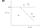
- multiple state regions are set for the motor temperature Tm and the motor current Im to indicate the state of the motor 61.
- the multiple state regions include an abnormal region A1, a demagnetization region A2, and a normal region A3.
- the abnormal region A1 is a region indicating that an abnormality in the rotor magnet 63a is likely to occur.
- the abnormal region A1 is also a region indicating that the motor temperature Tm has risen to a level corresponding to an abnormality in the rotor magnet 63a or the motor 61. If the state of the motor 61 continues to be in the abnormal region A1, there is a risk or possibility that an abnormality will occur in the rotor magnet 63a or the motor 61 even if the duration is short. Furthermore, the longer the duration, the higher the risk or possibility that an abnormality will occur in the rotor magnet 63a or the motor 61.
- the demagnetized area A2 and the normal area A3 are areas that indicate that the rotor magnet 63a is less likely to have an abnormality than the abnormal area A1.
- the demagnetized area A2 and the normal area A3 are areas that indicate that the rotor magnet 63a is normal, and are sometimes referred to as normal areas.
- the demagnetized area A2 and the normal area A3 are also areas that indicate that the motor temperature Tm has not risen to a level that corresponds to an abnormality in the rotor magnet 63a or the motor 61.
- the demagnetized area A2 and the normal area A3 are areas that are different from the abnormal area A1, and are areas that indicate that the motor temperature Tm is lower than the abnormal area A1.
- the normal region A3 is a region that does not correspond to an abnormality in the rotor magnet 63a and indicates that demagnetization of the rotor magnet 63a is less likely to occur than in the demagnetization region A2.
- demagnetization of the rotor magnet 63a hardly occurs.
- the demagnetization region A2 is a region that indicates that the rotor magnet 63a is likely to demagnetize, within a range that does not correspond to an abnormality of the rotor magnet 63a.
- the rotor magnet 63a is gradually demagnetized when the rotor magnet 63a is in the demagnetization region A2. For example, if the rotor magnet 63a is made of a neodymium magnet, the demagnetization of the neodymium magnet is likely to progress significantly when the motor 61 is in a high-temperature, high-current region such as the demagnetization region A2.
- the demagnetization cumulative time is the accumulated value of the time that the motor 61 is in the demagnetization region A2.
- the demagnetization cumulative time is the total value of all the time that the motor 61 is in the demagnetization region A2 after the eVTOL 10 is manufactured. The time that the motor 61 is in the abnormal region A1 or normal region A3 is not included in the demagnetization cumulative time.
- a first boundary line LB1 and a second boundary line LB2 exist for the abnormal region A1, the demagnetized region A2, and the normal region A3.
- the first boundary line LB1 indicates the boundary between the abnormal region A1 and the demagnetized region A2 and the normal region A3.
- the first boundary line LB1 indicates that the boundary between the abnormal region A1 and the normal region is the upper limit temperature TLB1.
- the upper limit temperature TLB1 is the upper limit value of the normal region.
- the first boundary line LB1 extends parallel to the axis of the motor current Im.
- the second boundary line LB2 indicates the boundary between the demagnetization region A2 and the normal region A3 in the normal region.
- the second boundary line LB2 extends so as to be inclined with respect to both the axis of the motor current Im and the axis of the motor temperature Tm.
- the second boundary line LB2 extends so that the state of the motor 61 is more likely to be included in the demagnetization region A2 the greater the value of at least one of the motor temperature Tm and the motor current Im.
- demagnetization of the rotor magnet 63a is likely to occur if the motor current Im is large even when the motor temperature Tm is low.
- demagnetization of the rotor magnet 63a is likely to occur if the motor temperature Tm is high even when the motor current Im is small.
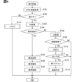
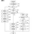
- the flight control device 40 performs flight control processing.
- the flight control processing will be explained with reference to the flowchart in FIG. 4.
- the flight control device 40 repeatedly executes the flight control processing at a predetermined control period.
- the flight control device 40 acquires eVTOL information in step S101.
- the eVTOL information is information that indicates the state of the eVTOL 10. Examples of the eVTOL information include information that indicates the flight state of the eVTOL 10 and information that indicates the state of each of the multiple propulsion devices 100. Information that indicates the state of the propulsion devices 100 includes detection signals from the temperature sensor 65 and the current sensor 66. Examples of the eVTOL information include information input from an external device to the flight control device 40 via the communication unit 34.
- step S102 the flight control device 40 determines whether the eVTOL 10 is in flight. For example, after the eVTOL 10 begins takeoff or before it has completed landing, it is determined that the eVTOL 10 is in flight. Also, while the eVTOL 10 is preparing for takeoff or after it has completed landing, it is determined that the eVTOL 10 is not in flight.
- the flight control device 40 executes the processing of steps S103 to S113 individually for each of the multiple propulsion devices 100.
- steps S103 to S111 that are executed for one propulsion device 100 are basically described. It is also assumed that the processing of steps S103 to S111 has been completed for the other propulsion devices 100.
- step S103 the flight control device 40 detects or calculates the motor temperature Tm.
- the motor temperature Tm is a parameter that indicates the driving state of the motor 61, and corresponds to the driving information.
- the function of the flight control device 40 that executes the processing of step S103 corresponds to the information acquisition unit.
- step S104 the flight control device 40 determines whether the state of the motor 61 is in the abnormal region A1. For example, the flight control device 40 determines whether the motor temperature Tm is higher than the upper limit temperature TLB1. If the motor temperature Tm is higher than the upper limit temperature TLB1, the flight control device 40 determines that the state of the motor 61 is in the abnormal region A1.
- the flight control device 40 performs abnormality response processing in steps S105 to S107.
- the abnormality response processing is processing for responding to an abnormality in the rotor magnet 63a.
- the flight control device 40 performs abnormality storage processing in step S105.
- processing is performed to store in the memory 43 or the like that the state of the motor 61 is in the abnormal region A1.
- the abnormality storage processing it is stored that the motor temperature Tm has risen to such an extent that it corresponds to an abnormality in the rotor magnet 63a or the motor 61.
- an abnormality flag is set in the management storage unit or the like.
- the abnormality flag is a flag for indicating that the state of the motor 61 is in the abnormal region A1.
- the management memory unit has volatile memory and non-volatile memory.
- volatile memory examples include RAM.
- RAM is an abbreviation for Random Access Memory.
- non-volatile memory examples include memories 43 and 83.
- Flags such as abnormality flags are stored in non-volatile memory. Memory data such as flags stored in the non-volatile memory of the management memory unit is not erased even if the power supply to eVTOL 10 is cut off, and remains in the management memory unit when the power supply to eVTOL 10 is turned on again. Flags such as abnormality flags may be stored in volatile memory such as RAM.
- the flight control device 40 performs an abnormality notification process in step S106.
- the abnormality notification process processing is performed to notify that the state of the motor 61 is in the abnormal region A1.
- the pilot or external facilities are notified that the motor temperature Tm has risen to such an extent that it corresponds to an abnormality in the rotor magnet 63a or the motor 61. Notification of various information is sometimes referred to as notifying various information.
- the flight control device 40 performs an abnormality limiting process in step S107.
- a process for limiting the motor current Im is performed.
- the motor temperature Tm decreases, and the state of the motor 61 is more likely to transition from the abnormal region A1 to the normal region.
- abnormalities in the rotor magnet 63a and the motor 61 are more likely to be resolved.
- the motor current Im is shut off.
- step S108 the flight control device 40 obtains the motor current Im by detection or calculation.
- the motor current Im is a parameter that indicates the driving state of the motor 61, and corresponds to the driving information.
- the function of the flight control device 40 that executes the processing of step S108 corresponds to the information acquisition unit.
- the flight control device 40 performs a management process to manage the demagnetization of the rotor magnet 63a in steps S109 to S113.
- the demagnetization state of the rotor magnet 63a is managed.
- the demagnetization state indicates the state of demagnetization of the rotor magnet 63a, such as whether or not demagnetization of the rotor magnet 63a has occurred.
- the demagnetization state includes the degree of demagnetization of the rotor magnet 63a.
- the degree of demagnetization indicates the extent to which the demagnetization of the rotor magnet 63a has progressed.
- the degree of demagnetization is sometimes referred to as the degree of deterioration of the rotor magnet 63a.
- the function that executes the processing of steps S109 to S113 in the flight control device 40 corresponds to the demagnetization management unit.
- step S109 the flight control device 40 determines whether the state of the motor 61 is in the demagnetization region A2.
- the motor temperature Tm and motor current Im are used for this determination.
- the flight control device 40 determines whether the current state of the motor 61 is in the demagnetization region A2.
- the motor temperature Tm and motor current Im acquired in steps S103 and S108 in the current flight control process are used as the current motor temperature Tm and motor current Im.
- step S110 the flight control device 40 counts the demagnetization counter Cd.
- the flight control device 40 adds a predetermined additional value to the demagnetization counter Cd.
- the additional value is sometimes called a count-up amount.
- the flight control device 40 sets the additional value to 1 and increments the demagnetization counter Cd by 1.
- the count value of the demagnetization counter Cd indicates the accumulated demagnetization time.
- the flight control device 40 obtains the degree of demagnetization of the rotor magnet 63a by counting the demagnetization counter Cd.
- the demagnetization counter Cd is set in the management memory unit.
- the demagnetization counter Cd may be counted as a RAM value of the management memory unit.
- the count value of the demagnetization counter Cd includes motor history information.
- the motor history information is information indicating the past state of the motor 61 as history.
- the motor history information is information indicating the history of the motor 61 with respect to past flight control processing executed before this time.
- the history of the motor 61 includes the history of the motor temperature Tm and the history of the motor current Im.
- the history of the motor temperature Tm includes information indicating that the motor temperature Tm is a temperature higher than the second boundary line LB2 when the state of the motor 61 is in the demagnetization region A2.
- the history of the motor current Im includes information indicating that the motor current Im is a current higher than the second boundary line LB2 when the state of the motor 61 is in the demagnetization region A2.
- the function of executing the processing of step S110 in the flight control device 40 corresponds to the history acquisition unit.
- the flight control device 40 manages the demagnetization of the rotor magnet 63a using the counter value of the demagnetization counter Cd.
- step S111 the flight control device 40 determines whether the demagnetization counter Cd has reached the counter threshold value TCd.
- the counter threshold value TCd is a value determined in advance through testing or the like, and is stored in the management memory unit.
- the counter threshold value TCd is a value that indicates that the demagnetization counter Cd has counted to a certain extent that the demagnetization of the rotor magnet 63a has progressed.
- step S109 the flight control device 40 determines whether the accumulated demagnetization time has reached the threshold time.
- step S109 the state of the motor 61 being in the demagnetization region A2 corresponds to a state in which the conditions for demagnetization of the rotor magnet 63a are met.
- step S110 the count value of the demagnetization counter Cd corresponds to the accumulated driving time of the motor 61 in a state in which the conditions for demagnetization of the rotor magnet 63a are met.
- step S111 the counter threshold value TCd corresponds to the threshold time.
- the function of the flight control device 40 that executes the processing of steps S109 to S111 corresponds to the accumulation determination unit.
- steps S109 to S113 the flight control device 40 manages the demagnetization of the rotor magnet 63a using the determination results of steps S109 to S111.
- step S109 if the state of the motor 61 is not in the demagnetization region A2, the flight control device 40 determines that demagnetization of the rotor magnet 63a is unlikely to occur and ends the flight control process. Also, in step S111, if the demagnetization counter Cd has not reached the counter threshold value TCd, the flight control device 40 determines that demagnetization of the rotor magnet 63a has not progressed much and ends the flight control process.
- step S112 the flight control device 40 sets a first flag in the management memory unit.
- the first flag is a flag indicating that the demagnetization counter Cd has reached the counter threshold value TCd.
- the first flag is a flag indicating that demagnetization of the rotor magnet 63a may have progressed to a certain extent.
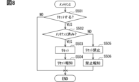
- the flight control device 40 performs demagnetization response processing in step S113.
- the demagnetization response processing will be explained with reference to the flowchart shown in FIG. 5.
- the flight control device 40 determines whether the first flag is set.
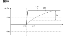
- the flight control device 40 proceeds to step S202 and calculates the correction amount Ac.
- the flight control device 40 performs motor control for the motor 61 so that the motor output, such as the output torque, becomes the target output, such as the target torque.
- the motor control feedback control, learning control, etc. are performed on the motor current Im so that the motor output becomes the target output.
- the correction amount Ac is calculated so that the motor output becomes the target output, and the correction amount Ac is used to control the motor current Im.
- the target current is calculated using the target output, and the target current is corrected with the correction amount Ac to control the motor current Im.
- the target current is a target value of the motor current Im, and is calculated according to the target output using a map, an arithmetic expression, etc.
- the motor output is calculated using the motor current Im, etc.
- the motor output corresponds to the output value
- the target output corresponds to the target value.
- the target current is sometimes called the control initial value.
- step S203 the flight control device 40 determines whether the correction amount Ac is equal to or greater than the correction threshold value TAc.
- the correction threshold value TAc is a value determined in advance by testing or the like, and is stored in the memory 43 or the like. Determining whether the correction amount Ac is equal to or greater than the correction threshold value TAc corresponds to determining whether the correction amount Ac is excessive, and determining whether the magnetic force deficiency condition for the rotor magnet 63a is satisfied.
- the deficiency condition is a condition that indicates a magnetic force deficiency due to the progress of demagnetization for the rotor magnet 63a.
- the correction amount Ac being equal to or greater than the correction threshold value TAc corresponds to the correction amount Ac being excessive, and the magnetic force deficiency condition for the rotor magnet 63a being satisfied.
- the function of executing the processing of step S203 in the flight control device 40 corresponds to the correction determination unit and the progress determination unit.
- the flight control device 40 proceeds to step S204 and sets a second flag in the management memory unit.
- the second flag is a flag indicating that the correction amount Ac is equal to or greater than the correction threshold value TAc.
- the second flag is a flag indicating that demagnetization of the rotor magnet 63a has progressed to a certain extent.
- step S205 the flight control device 40 performs second limit range processing.
- the second limit range processing is processing for adjusting the limit range for limiting the motor current Im in accordance with the motor temperature Tm.
- the degree of limiting the motor current Im is adjusted.
- a current limit value for limiting the maximum value of the motor current Im is set.
- the current limit value is set to a value according to the degree of limiting the motor current Im. The greater the degree of limiting the motor current Im, the smaller the current limit value is set to.
- the current limit value is set with respect to the target current.
- the current limit value limits the maximum value of the motor current Im by limiting the maximum value of the target current.
- a current limit value is set for the motor current Im, and the motor output and output torque are limited by the current limit value.
- an output limit value for limiting the motor output and a torque limit value for limiting the output torque may also be set. Even in a configuration in which an output limit value and a torque limit value are set, the motor current Im is still limited.
- the second restricted range processing will be described with reference to the flowchart shown in FIG. 6.
- the flight control device 40 determines which of multiple temperature ranges the motor temperature Tm is included in.
- the multiple temperature ranges include a low range, a medium range, and a high range.
- the low range is a range of temperatures lower than the medium range.
- the high range is a range of temperatures higher than the medium range.
- step S301 the flight control device 40 determines whether the motor temperature Tm is lower than the first temperature threshold T1.
- the first temperature threshold T1 is a value determined in advance through testing or the like, and is stored in the memory 43 or the like.
- the flight control device 40 determines whether the motor temperature Tm is in the low range by determining whether the motor temperature Tm is lower than the first temperature threshold T1. If the motor temperature Tm is lower than the first temperature threshold T1, the flight control device 40 determines that the motor temperature Tm is in the low range.
- the flight control device 40 determines in step S302 whether the motor temperature Tm is lower than the second temperature threshold T2.
- the second temperature threshold T2 is set to a value higher than the first temperature threshold T1.
- the second temperature threshold T2 is a value determined in advance through testing or the like, and is stored in the memory 43 or the like. If the motor temperature Tm is equal to or higher than the first temperature threshold T1, the flight control device 40 determines whether the motor temperature Tm is in the intermediate range by determining whether the motor temperature Tm is lower than the second temperature threshold T2. If the motor temperature Tm is equal to or higher than the first temperature threshold T1 and lower than the second temperature threshold T2, the flight control device 40 determines that the motor temperature Tm is in the intermediate range.
- the flight control device 40 proceeds to step S303 and performs low range processing.
- low range processing the degree of limitation of the motor current Im is adjusted in accordance with the fact that the motor temperature Tm is in the low range.
- the degree of limitation of the motor current Im is set to a looser value.
- the degree of limitation is set so that the motor current Im is not limited.
- the flight control device 40 sets the current limit value to the maximum output value for the motor current Im.
- the maximum output value is the maximum value of the motor current Im in the range that the motor 61 can output.
- the maximum output value is a value determined according to the rated output of the motor 61.
- the flight control device 40 may not set a current limit value so that the motor current Im is not limited.
- the flight control device 40 proceeds to step S304 and performs intermediate range processing.
- intermediate range processing the degree of limitation of the motor current Im is set in accordance with the fact that the motor temperature Tm is in the intermediate range.
- the degree of limitation of the motor current Im in intermediate range processing is set to be stricter than the degree of limitation of the motor current Im in low range processing.
- the degree of limitation is set so that the motor current Im is limited.
- the flight control device 40 sets the current limit value to a value smaller than the maximum output value for the motor current Im and larger than zero.
- the current limit value is set to a value such as 50% of the maximum output value.
- the current limit value may be variably set according to the motor temperature Tm within a range smaller than the maximum output value and larger than zero.
- the flight control device 40 proceeds to step S305 and performs higher range processing.
- the degree of limitation of the motor current Im is set in accordance with the fact that the motor temperature Tm is in the higher range.
- the degree of limitation of the motor current Im in higher range processing is set to be stricter than the degree of limitation of the motor current Im in intermediate range processing. For example, in higher range processing, the degree of limitation is set so that the motor current Im is cut off. In this case, the flight control device 40 sets the current limit value to zero. In other words, the flight control device 40 sets the current limit value so that the drive of the motor 61 is stopped.
- the flight control device 40 determines whether or not restricted flight of the eVTOL 10 is possible in step S206.
- Restricted flight refers to flight of the eVTOL 10 with the motor current Im restricted to the current limit value.
- a case in which restricted flight of the eVTOL 10 is possible is when the target current for the motor current Im is smaller than the current limit value. In this case, even if the current limit value is set, the motor current Im is not restricted by the current limit value, so restricted flight of the eVTOL 10 is possible.
- Another case in which restricted flight of the eVTOL 10 is possible is when flight of the eVTOL 10 is possible by driving another propulsion device 100 for which the second flag is not set. In this case, the flight control device 40 performs processing for restricted flight of the eVTOL 10, such as processing for changing the target output and target torque for the other propulsion device 100.
- the second limiting process is a process for limiting the motor current Im.
- motor control is performed in a state in which the motor current Im is limited by the current limiting value.
- the flight control device 40 adjusts the degree of limiting the motor current Im according to the motor temperature Tm using the current limiting value set in the above step S205.
- the flight control device 40 can limit the motor current Im by performing the second limiting process when the magnetic force deficiency condition is satisfied for the rotor magnet 63a.
- the function of executing the processes of steps S205 and S207 in the flight control device 40 corresponds to the temperature response unit and the current limiting unit.
- the flight control device 40 limits the motor current Im using the current limiting value set in step S303 above.
- the current limiting value is set to the maximum output value, so that the motor current Im is not limited by the current limiting value. For this reason, the flight control device 40 does not limit the motor current Im in steps S207 and S303.
- the function of the flight control device 40 that executes the processing of steps S207 and S303 corresponds to the non-limiting section.
- the flight control device 40 limits the motor current Im using the current limit value set in step S304 above.
- the current limit value is set to a value smaller than the maximum output value and greater than zero. Therefore, in steps S207 and S304, the flight control device 40 limits the motor current Im using the current limit value so as not to cut it off.
- the function of the flight control device 40 to execute the processing of steps S207 and S304 corresponds to the specific limiting unit.
- the flight control device 40 limits the motor current Im using the current limit value set in step S305 above. In this case, the current limit value is set to zero. Therefore, in steps S207 and S305, the flight control device 40 cuts off the motor current Im so that the motor current Im does not flow.
- the function of the flight control device 40 that executes the processes of S207 and S305 corresponds to the current cutoff unit.
- the current limit value is set according to the motor temperature Tm.
- the flight control device 40 selects which of the above steps S303 to S305 to set the current limit value according to the motor current Im in steps S301 and S302.
- the flight control device 40 also selects the non-limiting section, the current limiting section, and the current interrupting section according to the motor temperature Tm.
- the function of the flight control device 40 that executes the processing of steps S301 and S302 corresponds to the limit selection section.
- the flight control device 40 proceeds to step S215 and performs demagnetization notification process.
- demagnetization notification process demagnetization information of the rotor magnet 63a is notified via the communication unit 34, etc. For example, the demagnetization information is notified to a pilot or an external device. The demagnetization information is also stored in the memory 43, etc. The demagnetization information is notified to an operator or a maintenance device via the memory 43, etc.
- the demagnetization information is information related to the demagnetization of the rotor magnet 63a.
- the demagnetization information includes information indicating the demagnetization state and degree of demagnetization of the rotor magnet 63a. In the demagnetization notification process, it is notified that the current state of the motor 61 is in the demagnetization region A2, that the accumulated demagnetization time has reached the threshold time, etc.
- the demagnetization notification process When proceeding to step S215 after step S207 as in this case, the demagnetization notification process notifies that the correction amount Ac is equal to or greater than the correction threshold value TAc. In other words, the demagnetization notification process notifies that the magnetic force deficiency condition is met for the rotor magnet 63a.
- the function of executing the process of step S215 in the flight control device 40 corresponds to the notification execution unit. Furthermore, the demagnetization notification process notifies that the eVTOL 10 is capable of restricted flight, that the second restriction process has been executed, and so on. Regarding the second restriction process, it notifies whether the motor temperature Tm is in the low range, medium range, or high range, and so on.
- step S215 the flight control device 40 proceeds to step S216 and performs restriction response processing.
- restriction response processing will be explained later.
- step S208 the flight control device 40 sets a third flag in the management memory unit.
- the third flag is a flag indicating that the correction amount Ac is equal to or greater than the correction threshold value TAc and restricted flight of the eVTOL 10 is not possible.
- the third flag is also a flag indicating that the second restriction process is not to be executed when the second flag is set.
- the flight control device 40 performs a second mitigation process in step S209.
- the second mitigation process is a process for prioritizing the flight of the eVTOL 10 over the limitation of the motor current Im.
- the limitation of the motor current Im is relaxed. That is, in the second mitigation process, the degree of limitation of the motor current Im is set lower.
- the degree of limitation of the motor current Im is adjusted so that the limitation of the motor current Im is relaxed compared to the second limitation process in step S207 above.
- the second mitigation process is a process for temporarily mitigating the limitation of the motor current Im, on the premise that appropriate measures will be reliably taken during maintenance, which will be described later, after the eVTOL 10 has landed at a destination, etc.
- the fact that limited flight of the eVTOL 10 is not possible corresponds to the fact that the motor current Im is insufficient for propulsion of the eVTOL 10 when the second limiting process limits the motor current Im.
- the function of executing the process of step S209 in the flight control device 40 corresponds to the limit relaxation section.
- the motor current Im is limited so that the limit on the motor current Im is relaxed compared to the second restriction process.
- the flight control device 40 does not limit the motor current Im as in step S303 above, and also relaxes the correction limit on the correction amount Ac.
- a correction amount range is set to limit the magnitude of the correction amount Ac.
- the correction amount Ac is not set to a value that exceeds the correction amount range.
- the correction amount Ac is set to a value that is equal to or less than the upper limit value of the correction amount range and equal to or greater than the lower limit value of the correction amount range.
- the correction amount range is set based on the magnitude of the target current.
- the upper limit of the correction amount range is set to +20% of the target current
- the lower limit is set to -20% of the target current.
- the flight control device 40 performs a process to widen the correction amount range as a relaxation of the correction amount range. In this process, at least one of the upper limit and lower limit of the correction amount range is changed. For example, the flight control device 40 changes the upper limit of the correction amount range to +40% of the target current. Meanwhile, the lower limit of the correction amount range is maintained as -20% of the target current.
- the flight control device 40 does not limit the motor current Im, as in step S303 above. Therefore, in the second mitigation process, when the motor temperature Tm is in the intermediate range, the same process as in step S303 above is performed, rather than the same process as in step S304 above, thereby mitigating the limit on the motor current Im.
- the flight control device 40 limits the motor current Im with a current limit value so as not to cut off the motor current Im, as in step S304 above. Therefore, in the second mitigation process, when the motor temperature Tm is in the higher range, the same process as in step S304 above is performed, rather than the same process as in step S305 above, thereby mitigating the limit on the motor current Im.
- the flight control device 40 sets a prohibition flag in the management memory unit in step S210.
- the prohibition flag is a flag for prohibiting the eVTOL 10 from taking off again.
- a retake is when the eVTOL 10 takes off again after landing at a destination or the like and ending the current flight.
- the prohibition flag is also a flag for restricting takeoff, such as a retake, of the eVTOL 10.
- the flight control device 40 restricts the takeoff of the eVTOL 10 when the magnetic force deficiency condition is met for the rotor magnet 63a.
- the function of the flight control device 40 that executes the processing of step S210 corresponds to the takeoff restriction unit.
- the flight control device 40 performs prohibition processing to prohibit the eVTOL 10 from taking off again.
- the prohibition processing includes setting a prohibition flag. Examples of prohibition processing include processing to restrict operations for re-taking off the eVTOL 10 and processing to restrict the propulsion device 100 from operating to re-taking off the eVTOL 10.
- the prohibition processing can restrict the eVTOL 10 from taking off again.
- the prohibition processing is sometimes referred to as a restriction processing.
- the flight control device 40 After performing the second mitigation process and setting the prohibition flag, the flight control device 40 proceeds to step S215 and performs the demagnetization notification process.
- the demagnetization notification process notifies that the magnetic force deficiency condition is met for the rotor magnet 63a, just as when proceeding to step S215 after step S207.
- this demagnetization notification process notifies that the eVTOL 10 is not capable of restricted flight and that the second mitigation process has been performed.
- the second mitigation process notifies whether the motor temperature Tm is in the low, medium, or high range.
- this demagnetization notification process notifies that re-takeoff of the eVTOL 10 is restricted.
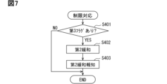
- step S215 the flight control device 40 performs restriction response processing in step S216.
- the restriction response processing will be described with reference to the flowchart shown in FIG. 7.
- step S401 shown in FIG. 7 the flight control device 40 determines whether or not the third flag is set. When the third flag is set, there are cases where the process proceeds to step S216 after it is determined in step S206 that the eVTOL 10 is capable of restricted flight, and cases where the process proceeds to step S216 after it is determined that the eVTOL 10 is not capable of restricted flight.
- step S206 The result of the determination in step S206 as to whether or not the eVTOL 10 is capable of restricted flight may change depending on the flight state of the eVTOL 10. For this reason, the increase or decrease in the target output and target current depending on the flight state of the eVTOL 10 is reflected in the result of the determination as to whether or not the eVTOL 10 is capable of restricted flight. For example, even if the previous flight control process determined that the eVTOL 10 was not capable of restricted flight and the third flag was set, the current flight control process may determine that the eVTOL 10 is capable of restricted flight and perform the second restriction process.
- step S402 the flight control device 40 performs the second mitigation process in the same manner as in step S209 above. In this way, even if step S206 in the current flight control process determines that the eVTOL 10 is capable of restricted flight, the flight control device 40 performs the second mitigation process if the third flag is set.
- the function of the flight control device 40 that executes the process of step S402 corresponds to the restriction mitigation unit.
- the flight control device 40 performs the second mitigation notification process in step S403.
- the second mitigation notification process it is notified that the third flag has been set, that the second mitigation notification process will be performed even if the eVTOL 10 is capable of restricted flight, etc.
- the second mitigation notification process it is notified that the magnetic force deficiency condition is met for the rotor magnet 63a, similar to the demagnetization notification process.
- the function of executing the process of step S403 in the flight control device 40 corresponds to the notification execution unit.
- step S402 If there is no third flag in step S402, the flight control device 40 ends this restriction response process as is. In this case, the flight control device 40 ends this flight control process as is.
- a case in which there is no third flag is when the second mitigation process has never been performed in step S209 during the flight of the eVTOL 10.
- step S203 if the correction amount Ac is not equal to or greater than the correction threshold value TAc, the flight control device 40 proceeds to step S211.
- the flight control device 40 performs a first limit range process in step S211.
- the first limit range process is a process for adjusting the limit range of the motor current Im.
- the first limit range process is a process for adjusting the limit range of the motor current Im so as to relax the limit on the motor current Im compared to the second limit range process.
- the degree of limitation on the motor current Im is adjusted according to the motor temperature Tm.
- step S212 the flight control device 40 determines whether the eVTOL 10 is capable of limited flight, similar to step S206 above. If the eVTOL 10 is capable of limited flight, the flight control device 40 proceeds to step S213 and performs a first limiting process.
- the first limiting process is a process for limiting the motor current Im.
- the flight control device 40 adjusts the degree of limiting the motor current Im according to the motor temperature Tm, using the current limit value set in step S211 above. In the first limiting process, the motor current Im is limited so as to relax the limit on the motor current Im compared to the second limiting process.
- the flight control device 40 proceeds to step S215 and performs the demagnetization notification process.
- the demagnetization notification process notifies that the correction amount Ac is not equal to or greater than the correction threshold value TAc. In other words, this demagnetization notification process notifies that the magnetic force deficiency condition is not met for the rotor magnet 63a.
- This demagnetization notification process also notifies that the eVTOL 10 is capable of restricted flight, that the first restriction process has been performed, and so on.
- the first mitigation process is a process for prioritizing flight of the eVTOL 10 over the limitation of the motor current Im.
- the limitation of the motor current Im is relaxed. That is, in the first mitigation process, the degree of limitation of the motor current Im is set to a low level.
- the degree of limitation of the motor current Im is adjusted so that the limitation is relaxed compared to the first limitation process in step S213 above.
- the degree of limitation of the motor current Im is adjusted so that the limitation is relaxed compared to the second mitigation process in step S209 above.
- the motor current Im is not limited regardless of the motor temperature Tm.
- the flight control device 40 proceeds to step S215 and performs the demagnetization notification process.
- the demagnetization notification process notifies the user that the magnetic force deficiency condition is not met for the rotor magnet 63a.
- the current demagnetization notification process also notifies the user that the eVTOL 10 is not capable of restricted flight, that the first mitigation process has been performed, and so on.
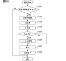
- step S114 the flight control device 40 performs maintenance processing in step S114.
- the maintenance processing is performed when the eVTOL 10 is not flying, such as after the eVTOL 10 lands or before takeoff. The maintenance processing will be described with reference to the flowchart shown in FIG. 8.
- step S501 shown in FIG. 8 the flight control device 40 determines whether or not a reset process has been requested.
- the reset process is a process for resetting various flags, etc. Examples of the various flags include an abnormality flag and a first flag.
- the flight control device 40 determines whether or not a reset request for a reset process has been input.
- a reset request is input to the flight control device 40 when an operator such as a pilot operates an operating unit of a maintenance device, etc.
- a reset request is input to the flight control device 40 from an appropriate tool such as a maintenance device only when an operator performs an operation for a reset request using an appropriate tool or procedure. If a reset request is input to the flight control device 40, the flight control device 40 determines that the reset process should be performed and proceeds to step S502.
- step S502 the flight control device 40 determines whether or not maintenance has been performed on the eVTOL 10.
- the flight control device 40 determines whether or not a maintenance record indicating that maintenance has been performed is stored in the management memory unit.
- the maintenance record is a record indicating that maintenance was performed after the flight of the eVTOL 10 was completed.
- the maintenance device or the like stores the maintenance record in the management memory unit. Maintenance includes work to service the eVTOL 10, work to inspect the eVTOL 10, work to replace parts of the eVTOL 10, etc.
- step S503 the flight control device 40 performs a reset process in step S503.
- various flags and the like are reset. For example, in the reset process, flags set in the management memory unit among the various flags are cleared to an initial value such as zero.
- the demagnetization counter Cd may be reset.
- the reset request includes a request to reset the demagnetization counter Cd.
- the demagnetization counter Cd is reset.
- the demagnetization counter Cd is reset by clearing its counter value to an initial value such as zero.
- the management memory unit is capable of setting various flags and demagnetization counters Cd in states corresponding to each of the multiple propulsion devices 100.
- the management memory unit is also capable of setting various flags and demagnetization counters Cd in states corresponding to each of the multiple motors 61.
- the management memory unit be capable of setting multiple flags and demagnetization counters Cd for one propulsion device 100.
- the flight control device 40 performs a reset notification process in step S504.
- reset information indicating that various flags, etc. have been reset is notified to an operator or an external device.
- the reset information includes information indicating which of the various flags has been reset, information indicating whether the demagnetization counter Cd has been reset, etc.
- step S505 If maintenance has not been performed in step S502, the flight control device 40 proceeds to step S505.
- the flight control device 40 performs a reset prohibition process in step S505.
- the reset prohibition process is a process for prohibiting various flags, the demagnetization counter Cd, etc. from being reset.
- the flight control device 40 performs a prohibition notification process in step S506.
- the prohibition notification process reset prohibition information indicating that resetting of various flags, the demagnetization counter Cd, etc. is prohibited is notified to the operator or an external device.
- the reset prohibition information includes information such as the fact that maintenance has not been performed and the type of flag set in the management memory unit.
- the flight control device 40 manages the demagnetization of the rotor magnet 63a using drive information such as the motor temperature Tm and the motor current Im.
- drive information such as the motor temperature Tm and the motor current Im.
- the first and second limiting processes prevent the motor 61 from reaching a state of high temperature and high current.
- the first and second limiting processes make it difficult for demagnetization of the rotor magnet 63a to occur, preventing a decrease in performance of the motor 61.
- the first and second limiting processes can prevent the motor temperature Tm from becoming so high that it would be considered an abnormality in the motor 61.
- Tm motor temperature
- the mounting ability of the motor 61 will deteriorate and the weight and cost will increase as the size and cooling effect of the motor 61 increase.
- it is possible to improve the cooling effect by making the motor device 60 a liquid-cooled device.
- the motor current Im is limited by the first limiting process and the second limiting process, making it possible to avoid such a condition. Therefore, demagnetization of the rotor magnet 63a can be suppressed without increasing the output or cooling effect of the motor 61. Therefore, there is no need to increase the size, weight, or cost of the motor device 60 in order to suppress demagnetization of the rotor magnet 63a.
- the motor 61 In the eVTOL 10 as a manned aircraft, there is a strong demand for the motor 61 to be lightweight, while at the same time requiring high output of several tens to several hundreds of kW. In other words, there is a demand to increase the output density of the motor 61. In the motor 61, the higher the output density, the higher the motor temperature Tm tends to become. As the motor temperature Tm rises, the rotor magnet 63a becomes more susceptible to demagnetization. For this reason, a configuration in which the motor current Im is limited in a state in which the rotor magnet 63a is susceptible to demagnetization, as in this embodiment, is effective in suppressing demagnetization of the rotor magnet 63a in a manned aircraft.
- the flight control device 40 manages the demagnetization of the rotor magnet 63a using motor history information such as the demagnetization counter Cd.
- motor history information such as the demagnetization counter Cd.
- the flight control device 40 manages the demagnetization of the rotor magnet 63a using the result of the determination of whether the demagnetization counter Cd has reached the counter threshold value TCd. Since this determination result reflects the degree of demagnetization of the rotor magnet 63a, the flight control device 40 can manage the demagnetization state of the rotor magnet 63a by, for example, limiting the motor current Im according to the degree of demagnetization of the rotor magnet 63a. For example, when the demagnetization counter Cd has not reached the counter threshold value TCd, the motor current Im is not limited, thereby preventing a shortage of motor output. Furthermore, when the demagnetization counter Cd has reached the counter threshold value TCd, the demagnetization of the rotor magnet 63a can be prevented by limiting the motor current Im using the first limiting process or the second limiting process.
- the correction amount Ac is equal to or greater than the correction threshold value TAc, it is determined that the magnetic force deficiency condition is met for the rotor magnet 63a, and the motor current Im is limited by the second limiting process.
- the demagnetization of the rotor magnet 63a has progressed to the point where the magnetic force deficiency condition is met, further progression of the demagnetization can be prevented by limiting the motor current Im.
- the higher the motor temperature Tm the more likely demagnetization of the rotor magnet 63a occurs. For example, if the current motor temperature Tm is sufficiently low, the rotor magnet 63a is less likely to be demagnetized even if the motor current Im is large. For this reason, even if the correction amount Ac is equal to or greater than the correction threshold value TAc, if the current motor temperature Tm is low, the rotor magnet 63a is less likely to be demagnetized further.
- the flight control device 40 adjusts the degree of limitation of the motor current Im by the second limitation process according to the motor temperature Tm.
- the motor current Im can be adjusted according to the likelihood of demagnetization of the rotor magnet 63a.
- the demagnetization of the rotor magnet 63a can be more appropriately managed. For example, when the motor temperature Tm is low and demagnetization of the rotor magnet 63a is unlikely to occur, it is possible to prioritize preventing a shortage of the motor current Im over suppressing the demagnetization of the rotor magnet 63a. Also, when the motor temperature Tm is high and demagnetization of the rotor magnet 63a is likely to occur, it is possible to prioritize suppressing demagnetization of the rotor magnet 63a over ensuring the motor current Im.
- low range processing, intermediate range processing, and high range processing are selected according to the motor temperature Tm.
- the motor current Im is not limited
- the motor current Im is limited so as not to be cut off
- the motor current Im is cut off. Therefore, a configuration can be realized in which multiple stages of current limiting are applied to the motor current Im according to the motor temperature Tm.
- the current limiting is strict in the high temperature range where the motor temperature Tm is easily demagnetized, is not limited in the low temperature range where demagnetization is difficult, and is loosened in the intermediate range where demagnetization does not occur as much as in the high temperature range, so that the demagnetization of the rotor magnet 63a can be appropriately managed.
- the motor output such as the motor current Im
- the correction amount Ac is set to an excessively large value to compensate for this shortfall.
- the correction amount Ac is so excessive that it is equal to or greater than the correction threshold value TAc, the magnetic force deficiency condition for the rotor magnet 63a is met.
- the demagnetization notification process notifies the pilot, etc. that the correction amount Ac is equal to or greater than the correction threshold value TAc. For example, when the correction amount Ac is equal to or greater than the correction threshold value TAc, demagnetization information is stored and transmitted so that inspection or replacement can be performed before the demagnetization of the rotor magnet 63a progresses further.
- the limit on the motor current Im is relaxed by the second mitigation unit.
- priority can be given to ensuring that the motor current Im is not insufficient for propulsion of the eVTOL 10, rather than suppressing demagnetization of the rotor magnet 63a. Therefore, it is possible to achieve an appropriate balance between suppressing demagnetization of the rotor magnet 63a and ensuring the safety of the eVTOL 10.
- the flight control device 40 notifies the pilot or the like that a magnetic insufficiency condition is met for the rotor magnet 63a by a demagnetization notification process or the like.
- a demagnetization notification process or the like it is possible to notify the pilot or the like of the magnetic insufficiency of the rotor magnet 63a before the demagnetization of the rotor magnet 63a progresses to the point where an abnormality or performance degradation of the motor 61 occurs. Therefore, by performing inspections or part checks on the rotor magnet 63a before the motor 61 reaches an abnormality or performance degradation, it is possible to prevent the occurrence of an abnormality or performance degradation of the motor 61.
- the flight control device 40 restricts the takeoff of the eVTOL 10 when the magnetic force deficiency condition is met for the rotor magnet 63a. This makes it possible to avoid a situation in which the eVTOL 10 takes off again without maintenance of the motor 61 being performed, even though the magnetic force of the rotor magnet 63a is insufficient. This makes it possible to reliably prevent the safety of the eVTOL 10 from being reduced due to the magnetic force deficiency of the rotor magnet 63a.
- an abnormal region A1 and a demagnetization region A2 are set according to the motor temperature Tm as regions indicating the state of the motor 61.
- the abnormal region A1 has a temperature condition for the motor temperature Tm that quickly limits the motor current Im.
- the demagnetization region A2 has a temperature condition for the motor temperature Tm for determining demagnetization that is lower than the temperature condition of the abnormal region A1.
- the motor current Im is quickly limited by the abnormality limiting process. This makes it possible to prevent the output of the propulsion device 100 from being unintentionally insufficient due to the state of the motor 61 being in the abnormal region A1.
- the progress of demagnetization in the rotor magnet 63a can be monitored by determining whether the state of the motor 61 is in the abnormal region A1, the demagnetization region A2, or the normal region A3. This makes it possible to accept the risk that the demagnetization of the rotor magnet 63a will progress to a certain extent as the motor 61 is driven, while taking measures such as replacing parts before the demagnetization of the rotor magnet 63a actually affects the flight of the eVTOL 10.
- the demagnetization of the rotor magnet 63a is managed in accordance with the change in the correction amount Ac.
- the configurations, actions, and effects of the second embodiment that are not specifically described are the same as those of the first embodiment.
- the second embodiment will be described mainly with respect to the differences from the first embodiment.
- the flight control device 40 performs flight control processing in the same manner as in the first embodiment described above.
- the demagnetization response processing of the flight control processing will be described with reference to the flowchart in FIG. 9.
- the flight control device 40 performs the processing of steps S201 to S216 in the same manner as in the first embodiment described above.
- the flight control device 40 performs the processing of steps S601 and S602.
- the flight control device 40 calculates the smoothing value Sm in step S601.
- the smoothing value Sm is a value for smoothing the correction amount Ac.
- the smoothing value Sm is a value that smoothes the change in the correction amount Ac.
- the smoothing value Sm is calculated using Equation 1.
- Sm[t] ⁇ Ac[t]+(1- ⁇ ) ⁇ Sm[t-1]...Formula 1
- ⁇ is a value greater than zero and less than 1. That is, 0 ⁇ 1.
- [t] is the value acquired in the current demagnetization response process.
- [t-1] is the value acquired in the previous demagnetization response process.
- Sm[t] is the smoothing value Sm calculated in step S610 this time.
- Sm[t- 1] is the smoothing value Sm calculated in the previous step S601.
- Ac[t] is the correction amount Ac calculated in the current step S202.
- the smoothing value Sm is calculated based on the learning control Alternatively, the circumference value calculated by the following formula may be used.
- the smoothing value line LSm changes more gradually than the correction amount line LAC.
- the smoothing value line LSm is a line that shows the change in the smoothing value Sm.
- the correction amount line LAC is a line that shows the change in the correction amount Ac.
- the correction amount Ac is equal to or greater than the correction threshold value TAc.
- the flight control device 40 determines whether or not the sudden flag is set.
- the sudden flag is a flag that indicates that a sudden abnormality has occurred.
- a sudden abnormality is an abnormality that occurs suddenly, such as one that is accompanied by a sudden change in the correction amount Ac. Examples of sudden abnormalities include abnormalities that occur when a foreign object gets caught in the motor shaft or propeller shaft. Even if an abnormality occurs in the rotor magnet 63a or the motor 61 as the demagnetization of the rotor magnet 63a progresses, this abnormality is not included in the sudden abnormality. In other words, the sudden abnormality is not an abnormality caused by the demagnetization of the rotor magnet 63a.
- step S603 the flight control device 40 determines whether or not there is a deviation between the smoothing value Sm and the correction amount Ac. For example, the flight control device 40 determines whether or not the deviation amount Dt is greater than the deviation threshold value TDt.
- the deviation amount Dt is the difference between the smoothing value Sm and the correction amount Ac.
- the deviation threshold value TDt is a value determined in advance by testing or the like, and is stored in the memory 43 or the like.
- the flight control device 40 performs the processing of steps S204 to S216 in the same manner as in the first embodiment described above when the correction amount Ac is equal to or greater than the correction threshold value TAc.
- step S604 the flight control device 40 sets an unexpected flag in the management memory unit. As shown in FIG. 10, if an unexpected abnormality occurs at timing t11, the unexpected flag is set at timing t12, which is after timing t11. In this case, the discrepancy amount Dt is the difference between the smoothing value Sm and the correction amount Ac at timing t12.
- the flight control device 40 performs emergency response processing in step S605.
- the emergency response processing includes processing for storing the occurrence of a sudden abnormality in the memory 43, etc., and processing for notifying the pilot or external facilities, etc., of the occurrence of a sudden abnormality.
- the motor output such as the motor current Im, may be limited, and the drive of the motor 61 may be stopped.
- the tendency for demagnetization of the rotor magnet 63a to occur is reflected in the cumulative drive time.
- the configurations, actions, and effects of the third embodiment that are not specifically described are the same as those of the first embodiment.
- the third embodiment will be described with a focus on the differences from the first embodiment.
- the flight control process will be described with reference to the flowchart in FIG. 11.
- the flight control device 40 performs the process of steps S101 to S114 in the same manner as in the first embodiment. However, if the state of the motor 61 is in the demagnetization region A2 in step S109, the flight control device 40 proceeds to step S701.
- the function of the flight control device 40 that executes the process of steps S109 to S113 and S701 corresponds to the demagnetization management unit.
- the flight control device 40 performs a count correction process in step S701.
- the added value of the demagnetization counter Cd is corrected.
- the added value is a value added to the demagnetization counter Cd in step S110.
- the added value was a fixed value, but in this embodiment, the added value is a variable value.
- the flight control device 40 changes the added value depending on how easily the rotor magnet 63a is demagnetized. For example, the added value is variably set depending on where the state of the motor 61 is in the demagnetization region A2.
- the demagnetization area A2 includes a first demagnetization area A21, a second demagnetization area A22, and a third demagnetization area A23.
- the first demagnetization area A21 is an area where demagnetization of the rotor magnet 63a is less likely to occur than the second demagnetization area A22. For this reason, the addition value for the first demagnetization area A21 is set to a value smaller than the addition value for the second demagnetization area A22.
- the third demagnetization area A23 is an area where demagnetization of the rotor magnet 63a is more likely to occur than the second demagnetization area A22.
- the addition value for the third demagnetization area A23 is set to a value larger than the addition value for the second demagnetization area A22.
- the addition value for the first demagnetization area A21 is set to 1
- the addition value for the second demagnetization area A22 is set to 2
- the addition value for the third demagnetization area A23 is set to 3.
- step S701 the flight control device 40 proceeds to step S110 and adds an additional value to the demagnetization counter Cd.
- the longer the time that the motor 61 is in the third demagnetization region A23 the shorter the time that the demagnetization counter Cd is likely to reach the counter threshold value TCd.
- the longer the time that the motor 61 is in the first demagnetization region A21 the longer the time that the demagnetization counter Cd is likely to reach the counter threshold value TCd.
- weighting is applied to the region indicating the state of the motor 61 so that the added value of the demagnetization counter Cd is variably set according to how easily the rotor magnet 63a is demagnetized.
- the demagnetization region A2 the more easily the rotor magnet 63a is demagnetized in the region, the faster the demagnetization counter Cd increases.
- the processing burden on the flight control device 40 is more likely to increase compared to a configuration in which weighting is not applied, but the degree of demagnetization of the rotor magnet 63a can be accurately estimated.
- the demagnetization response process is performed when the accumulated demagnetization time during which the state of the motor 61 is in the demagnetization region A2 is relatively long.
- the demagnetization response process is performed when the correction amount Ac is relatively large.
- the flight control process will be described with reference to the flowchart in FIG. 13. As shown in FIG. 13, the flight control device 40 performs the processes of steps S101 to S108 and S112 to S114 in the same manner as in the first embodiment. However, after step S108, the flight control device 40 performs the processes of steps S801 and S802.
- step S801 and S802 the flight control device 40 performs the same processing as steps S202 and S203 in the first embodiment.
- step S801 the flight control device 40 calculates the correction amount Ac.
- the correction amount Ac is a parameter that indicates the driving state of the motor 61, and corresponds to the driving information.
- the function of the flight control device 40 that executes the processing of step S801 corresponds to the information acquisition unit.
- step S802 the flight control device 40 determines whether the correction amount Ac is equal to or greater than the correction threshold value TAc. Determining whether the correction amount Ac is equal to or greater than the correction threshold value TAc corresponds to determining whether the motor output is insufficient for the target output.
- the function in the flight control device 40 that executes the processing of step S802 corresponds to the output determination unit.
- the function in the flight control device 40 that executes the processing of steps S109 to S113 and S802 corresponds to the demagnetization management unit.
- the flight control device 40 performs the processes of steps S112 and S113. That is, the flight control device 40 performs demagnetization response processing in step S113.
- the demagnetization response processing will be explained with reference to the flowchart in FIG. 14.
- step S901 the flight control device 40 determines whether the correction amount Ac has reached the upper limit of the correction amount range.
- the correction amount Ac has reached the upper limit of the correction amount range, it may be necessary to set the correction amount Ac to a value greater than the upper limit of the correction amount range in order to bring the motor output closer to the target output.
- the motor output may be insufficient for the target output. In this case, the motor current Im is likely to be insufficient because the rotor magnet 63a has already been demagnetized to a certain extent.
- Determining whether the correction amount Ac has reached the upper limit of the correction amount range corresponds to determining whether the motor output is insufficient for the target output.
- the function of executing the processing of step S901 in the flight control device 40 corresponds to the output determination unit.
- the flight control device 40 proceeds to step S204 and sets the second flag.
- the second flag is a flag indicating that the correction amount Ac has reached the upper limit of the correction amount range.
- the second flag is a flag indicating that demagnetization of the rotor magnet 63a has progressed to a certain extent.
- step S902 the flight control device 40 calculates the output torque of the motor 61.
- the flight control device 40 calculates the output torque using the motor current Im, etc.
- the output torque is a parameter that indicates the driving state of the motor 61, and corresponds to the driving information.
- the function of the flight control device 40 that executes the processing of step S902 corresponds to the information acquisition unit.
- step S903 the flight control device 40 determines whether there is a torque shortage. That is, the flight control device 40 determines whether the output torque is insufficient relative to the target torque. For example, the flight control device 40 determines whether the torque difference between the output torque and the target torque is smaller than a predetermined torque threshold. If the torque difference is smaller than the torque threshold, the flight control device 40 determines that there is a torque shortage. Determining whether there is a torque shortage corresponds to determining whether the motor output is insufficient relative to the target output.
- the function of the flight control device 40 that executes the processing of step S903 corresponds to the output determination unit.
- step S207 If there is no torque deficiency, the flight control device 40 executes the second restriction process in step S207. If there is a torque deficiency, the flight control device 40 executes the second mitigation process in step S209.
- the flight control device 40 manages the demagnetization of the rotor magnet 63a using the result of the determination of whether the motor output is insufficient relative to the target output. Since this determination result reflects the degree of demagnetization of the rotor magnet 63a via the motor output, the flight control device 40 can manage the demagnetization state of the rotor magnet 63a by, for example, limiting the motor current Im according to the degree of demagnetization of the rotor magnet 63a. For example, when the correction amount Ac is not equal to or greater than the correction threshold value TAc, the motor current Im is not limited, thereby preventing the motor output from becoming insufficient. Furthermore, when the correction amount Ac is equal to or greater than the correction threshold value TAc, the demagnetization of the rotor magnet 63a can be prevented by limiting the motor current Im using the first limiting process or the second limiting process.
- the propulsion system 30 has a cooling mechanism capable of cooling the motor 61. Configurations, actions, and effects not specifically described in the fifth embodiment are similar to those in the first embodiment. The fifth embodiment will be described mainly with respect to differences from the first embodiment.
- the propulsion system 30 has a cooling device 110.
- the cooling device 110 is capable of cooling the motor 61.
- the cooling device 110 is included in the cooling mechanism.
- the cooling device 110 is provided in the eVTOL 10.
- the cooling device 110 cools at least the motor 61 of the EPU 50.
- the cooling device 110 is provided in the EPU 50.
- the driving source of the cooling device 110 is the motor 61.
- the cooling device 110 is driven by the motor 61.
- the cooling device 110 is an air-cooled or liquid-cooled cooling device.
- the air-cooled cooling device 110 has an air-cooled fan.
- the air-cooled fan is a blower fan that blows air as the motor 61 is driven.
- the air-cooled fan is fixed to the motor shaft.
- the air-cooled fans are arranged in the motor housing 70 and the inverter housing 90 along the motor shaft.
- the air-cooled fan cools the motor 61 and the inverter device 80 by flowing air, such as outside air, along the outer surfaces of the housings 70 and 90.
- the liquid-cooled cooling device 110 cools the motor 61 with a refrigerant such as water.
- the liquid-cooled cooling device 110 has a flow path forming section such as piping that forms a flow path, a refrigerant pump for flowing the refrigerant through the flow path, and a heat dissipation section for dissipating the heat of the refrigerant to the outside.
- the flow path is provided so that the refrigerant can easily cool the motor 61 and the inverter device 80.
- the refrigerant pump is driven in conjunction with the driving of the motor 61.
- the refrigerant pump is provided on the motor shaft, and pumps the refrigerant as the motor shaft rotates.
- the refrigerant may be a liquid refrigerant or a gas refrigerant.
- the inverter circuit 85 has multiple switching elements such as IGBTs and MOSFETs.
- each of the upper and lower arms of the upper and lower arm circuits is formed to include a switching element.
- the inverter circuit 85 drives the motor 61 by converting power through switching of the switching elements.
- the inverter circuit 85 corresponds to an inverter.
- the inverter control unit 81 drives the inverter circuit 85 by outputting a PWM signal as a command signal.
- the PWM signal is a pulse signal.
- the inverter control unit 81 changes the driving state of the motor 61, such as the motor rotation speed, by changing the frequency of the PWM signal.
- the frequency of the PWM signal is a frequency for driving the inverter circuit 85, and corresponds to the driving frequency.
- the frequency of the PWM signal is sometimes referred to as the PWM frequency.
- the PWM signal is generated using a carrier signal such as a triangular wave.
- the frequency of the PWM signal is the frequency of the carrier signal.
- the flight control process will be described with reference to the flowchart in FIG. 16.
- the flight control device 40 performs the processes of steps S101 to S114, similar to the first embodiment described above.
- the flight control device 40 performs the processes of steps S1001 to S1004 in addition to the process of step S114.
- the flight control device 40 performs landing response processing in step S1001.
- the landing response processing is processing that is performed in response to the landing of the eVTOL 10.
- the landing response processing will be described with reference to the flowchart shown in FIG. 17.
- the flight control device 40 determines whether or not the landing of the eVTOL 10 has been completed in step S1101 of the landing response process shown in FIG. 17. If the landing of the eVTOL 10 has not been completed, the flight control device 40 determines that the eVTOL 10 is flying and ends the landing response process. If the landing of the eVTOL 10 has been completed, the flight control device 40 proceeds to step S1102.
- step S1102 the flight control device 40 acquires the motor temperature Tm, similar to step S103 in the first embodiment.
- step S1103 the flight control device 40 determines whether the motor temperature Tm is equal to or higher than the first cooling threshold C1.
- the first cooling threshold C1 is a value determined in advance by testing or the like, and is stored in the memory 43 or the like.
- the first cooling threshold C1 is a value indicating that the motor temperature Tm is high enough that cooling of the motor 61 is necessary in the eVTOL 10 after landing, or a value indicating that demagnetization of the rotor magnet 63a may progress in the eVTOL 10 after landing.
- the first cooling threshold C1 corresponds to the cooling temperature. If the motor temperature Tm is equal to or higher than the first cooling threshold C1, the flight control device 40 determines that the motor 61 is too hot for the eVTOL 10 after landing.
- the first cooling threshold C1 is set to a temperature between the upper limit outside air temperature Tout and the upper limit temperature TLB1.
- the upper limit outside air temperature Tout is the highest upper limit temperature within the assumed range assumed for the outside air temperature of the eVTOL 10. This assumed range is the range of outside air temperatures assumed when the eVTOL 10 is on the ground.
- the upper limit outside air temperature Tout is assumed to be a temperature lower than the upper limit temperature TLB1.
- the first cooling threshold C1 is set to a temperature that is a predetermined temperature higher than the upper limit outside air temperature Tout.
- the first cooling threshold C1 is set to a temperature that is a predetermined temperature lower than the upper limit temperature TLB1.
- step S1104 the flight control device 40 performs a power-off prohibition process.
- a process is performed to prohibit the eVTOL 10 from being powered off.
- the flight control device 40 sets a prohibition flag in the memory 43 or the like to prohibit the eVTOL 10 from being powered off.
- the supply of power from the battery 31 to the EPU 50 is prohibited from being stopped. In other words, in the power-off prohibition process, the supply of power from the battery 31 to the EPU 50 is forcibly continued.
- the flight control device 40 restricts the power off of the eVTOL 10 by prohibiting the power off of the eVTOL 10.
- the power off prohibition process includes processes to prevent the power switch of the eVTOL 10 from being operated, and processes to prevent the power of the eVTOL 10 from being turned off even if the power switch of the eVTOL 10 is operated.
- the flight control device 40 performs a cooling process in step S1105.
- a process is performed to drive the motor 61 so that the cooling device 110 cools the motor 61.
- the flight control device 40 drives the motor 61 so that the eVTOL 10 does not fly even when the propeller 20 rotates, and so that the cooling device 110 cools the motor 61.
- the flight control device 40 controls the rotation speed of the motor 61 while limiting it so that the eVTOL 10 does not lift off the ground even when the propeller 20 rotates, and so that the attitude of the eVTOL 10 does not become unstable.
- the flight control device 40 sets the rotation speed of the motor 61, which is being driven to drive the cooling device 110, to a value smaller than the rotation speed of the motor 61, which is being driven to fly the eVTOL 10.
- the flight control device 40 sets the PWM frequency in the cooling process to a value smaller than the PWM frequency during flight of the eVTOL 10.
- the smaller the PWM frequency the less the number of switching times of the switching elements.
- the number of switching times of the switching elements in the inverter circuit 85 is likely to be smaller than the number of switching times during flight of the eVTOL 10. Therefore, in the cooling process, the heat generated in the inverter device 80 due to the operation of the inverter circuit 85 is likely to be smaller than the heat generated in the inverter device 80 during flight of the eVTOL 10.
- the function of executing the process of step S1105 in the flight control device 40 corresponds to a cooling execution unit. This cooling execution unit may be included in the demagnetization management unit.
- the number of switching times is the number of switching times per unit time.
- step S1106 the flight control device 40 determines whether the motor temperature Tm has fallen below the first stop threshold C1a.
- the first stop threshold C1a is a value determined in advance through testing or the like, and is stored in the memory 43 or the like.
- the first stop threshold C1a is a threshold for determining whether to stop cooling the motor 61 by the cooling device 110.
- the first stop threshold C1a is a value that indicates that the motor temperature Tm has been sufficiently reduced by the cooling process for the eVTOL 10 after landing. If the motor temperature Tm falls below the first stop threshold C1a, the flight control device 40 determines that the high temperature state in which the motor 61 was high has been resolved by the cooling process.
- the first stop threshold C1a is set to a temperature between the first cooling threshold C1 and the upper limit outside air temperature Tout.
- the first stop threshold C1a is set to a temperature that is a predetermined temperature lower than the first cooling threshold C1.
- the first stop threshold C1a is also set to a temperature that is a predetermined temperature higher than the upper limit outside air temperature Tout.
- the first stop threshold C1a may be set to the same temperature as the first cooling threshold C1 or to a temperature lower than the upper limit outside air temperature Tout. However, it is considered to be practically difficult for an air-cooled cooling device 110 to cool the motor temperature Tm to a temperature lower than the upper limit outside air temperature Tout.
- the flight control device 40 continues to perform the power off prohibition process and the cooling process until the motor temperature Tm becomes lower than the first stop threshold C1a.
- the flight control device 40 prohibits the cooling process from being stopped by performing the power off prohibition process while the cooling process is being performed. That is, in step S1104, the flight control device 40 restricts the power off of the eVTOL 10, thereby restricting the cooling device 110 from stopping cooling of the motor 61.
- the function of the flight control device 40 that executes the process of step S1104 corresponds to a stop regulation unit. This stop regulation unit may be included in the demagnetization management unit.
- the flight control device 40 performs a cooling process, which prevents heat from building up in the motor 61 and motor housing 70 after the eVTOL 10 lands. This makes it less likely that the motor temperature Tm will rise to the upper limit temperature TLB1 due to heat built up in the motor 61 and motor housing 70 after the eVTOL 10 lands. This prevents the state of the motor 61 from transitioning to the abnormal region A1 after the eVTOL 10 lands, which would cause the rotor magnet 63a to become demagnetized. In addition, because it is possible to prevent takeoff from starting with a high motor temperature Tm before the next takeoff, it is less likely that the motor temperature Tm will rise to the upper limit temperature TLB1 during takeoff.
- the flight control device 40 performs a cooling stop process in step S1107.
- the cooling stop process includes a process for stopping the cooling process and a process for stopping the operation of the cooling device 110. For example, in the cooling stop process, a process for stopping the operation of the motor 61 is performed, thereby stopping the operation of the cooling device 110.
- step S1108 the flight control device 40 performs a release process to release the power-off prohibition.
- a process is performed to permit the power to be turned off for the eVTOL 10.
- a prohibition flag for prohibiting the power to be turned off for the eVTOL 10 is cleared.
- a process is performed to enable the power switch of the eVTOL 10 to be operated.
- the landing response process will be explained in summary. If the eVTOL 10 is powered off after landing without cooling the motor 61, there is a concern that dead soak will occur in the eVTOL 10. For example, dead soak is a phenomenon in which the motor temperature Tm after landing is likely to be higher than the motor temperature Tm during flight after the eVTOL 10 is powered off, due to heat generated in the motor 61 during the flight of the eVTOL 10 being trapped in the motor device 60. In response to this, the motor 61 is cooled by the cooling process of the landing response process after the eVTOL 10 lands, thereby suppressing the occurrence of dead soak. Note that the function of executing the process of step S1001 in the flight control device 40 may be included in the demagnetization management unit.
- the drive inspection process is a process for inspecting the eVTOL 10 while driving the motor 61. This inspection includes an inspection of the drive state of the motor 61 and an inspection of the demagnetization state of the rotor magnet 63a. The drive inspection process will be explained with reference to the flowchart in FIG. 19.
- step S1201 of the drive inspection process shown in FIG. 19 the flight control device 40 determines whether or not there is a request for inspection drive of the motor 61.
- Inspection drive is to drive the motor 61 in order to perform a drive inspection.
- a request for inspection drive is input to the flight control device 40 when an operator operates the maintenance device or the operation unit of the eVTOL 10. If there is no request for inspection drive, the flight control device 40 determines that there is no need to perform a drive inspection of the motor 61 and ends the drive inspection process. If there is a request for inspection drive, the flight control device 40 proceeds to step S1202.
- the flight control device 40 performs inspection drive processing in step S1202.
- processing is performed to drive the motor 61 for inspection.
- the flight control device 40 drives the motor 61 so that the eVTOL 10 does not fly even if the propeller 20 rotates.
- the rotation speed of the motor 61 is limited so that the eVTOL 10 does not lift off the ground even if the propeller 20 rotates and so that the attitude of the eVTOL 10 does not become unstable.
- the rotation speed of the motor 61 is set to a value smaller than the rotation speed of the motor 61 driven to fly the eVTOL 10.
- step S1203 the flight control device 40 acquires the motor current Im, similar to step S108 in the first embodiment.
- step S1204 the flight control device 40 acquires the output torque Tr [Nm] of the motor 61.
- the output torque Tr is detected by a maintenance device including a torque sensor.
- the flight control device 40 detects the output torque Tr using the detection signal of the torque sensor.
- step S1205 the flight control device 40 determines whether the torque constant Km [Nm/A] is equal to or less than the constant threshold JKm. That is, the flight control device 40 determines whether the output torque Tr for the motor current Im is equal to or less than a predetermined value.
- the torque constant Km is a value indicating the torque per unit current.
- the flight control device 40 calculates the torque constant Km using the motor current Im and the output torque Tr.
- the constant threshold JKm is a value determined in advance through testing or the like, and is stored in the memory 43 or the like.
- the constant threshold JKm is a value indicating that the output torque Tr has decreased to the point where the torque constant Km is insufficient from the perspective of flying the eVTOL 10.
- the flight control device 40 determines that a torque abnormality has occurred and proceeds to step S1206.
- the flight control device 40 performs torque abnormality processing in step S1206.
- a diagnosis that a torque abnormality has occurred is stored in the memory 43 or the like as torque abnormality information.
- the flight control device 40 performs notification processing in step S1207. In the notification processing, the occurrence of a torque abnormality in the eVTOL 10 is notified to the pilot, external facilities, etc.
- the flight control device 40 determines that no torque abnormality has occurred and proceeds to step S1207 to perform notification processing. In this notification processing, the pilot, external facilities, etc. are notified that no torque abnormality has occurred in the eVTOL 10.
- step S1208 the flight control device 40 performs an inspection completion process.
- inspection completion information indicating that the drive inspection of the motor 61 has been completed is stored in the memory 43 or an external device such as a maintenance device.
- the inspection completion information includes the date and time when the drive inspection was performed, whether or not there was a torque abnormality, the value of the output torque Tr, the value of the torque constant Km, and so on.
- the worker performs part replacement work etc. according to the information recorded in the management storage unit or memory 43. For example, if flag history information indicating a history in which a deterioration flag has been set remains in the management storage unit, the worker replaces parts according to both the flag information during flight and the torque abnormality information during the drive inspection. Examples of deterioration flags include a first flag, a second flag, a third flag, etc.
- the worker may decide to replace parts such as the rotor 63 or rotor magnet 63a based only on the flag information acquired during the flight of the eVTOL 10, but may also decide on necessary measures such as part replacement after inspecting the eVTOL 10 again on the ground, such as by performing a drive inspection.
- step S1207 the flight control device 40 may report both the flag history information during flight and the torque abnormality information during the drive inspection. In addition, in step S1207, the flight control device 40 may report information indicating the demagnetization state of the rotor magnet 63a, information indicating the need for part replacement, etc.
- the flight control device 40 will report this history and the diagnosis results.
- the flight control device 40 will also report that the motor output has decreased due to the progression of irreversible demagnetization of the rotor magnet 63a, that the motor 61 or motor parts need to be replaced, etc.
- the flight control device 40 will report this history and the diagnosis results.
- the flight control device 40 will also report that the motor 61 has reached a state where the deterioration flag is set, but that irreversible demagnetization of the rotor magnet 63a has not actually progressed. In this case, the flight control device 40 may issue a report to request the operator to perform an additional inspection to confirm that no abnormalities have occurred in the motor 61.
- the flight control device 40 will report this history and the diagnosis results.
- the flight control device 40 will also report that the motor 61 is in a state where it cannot output normal power due to a factor other than demagnetization or deterioration of the rotor magnet 63a.
- the flight control device 40 reports that an abnormality has occurred in the EPU 50.
- the flight control device 40 may report that an inspection or investigation other than the drive inspection is required.
- the flight control device 40 will report this history and the diagnosis results. The flight control device 40 will also report that the EPU 50 is normal.
- the flight control device 40 proceeds to step S114 and performs maintenance processing.
- the flight control device 40 then proceeds to step S1003 and performs takeoff preparation processing.
- the takeoff preparation processing is a process that advances preparations for taking off the eVTOL 10. The takeoff preparation processing will be described with reference to the flowchart shown in FIG. 20.
- the flight control device 40 determines whether the power of the eVTOL 10 is on or not in step S1301 of the takeoff preparation process shown in FIG. 20. If the power of the eVTOL 10 is on, the battery 31 is in a state in which it can supply power to the EPU 50. In step S1302, the flight control device 40 determines whether the eVTOL 10 is on the ground or not. That is, the flight control device 40 determines whether the eVTOL 10 is in flight or not. If the eVTOL 10 is not in flight, the flight control device 40 determines that the eVTOL 10 is on the ground.
- step S1303 the flight control device 40 acquires the motor temperature Tm, similar to step S103 in the first embodiment described above.
- step S1304 the flight control device 40 determines whether the motor temperature Tm is equal to or higher than the second cooling threshold C2.
- the second cooling threshold C2 is a value determined in advance by testing or the like, and is stored in the memory 43 or the like.
- the second cooling threshold C2 is a value indicating that the motor temperature Tm is high enough that cooling of the motor 61 is necessary in the eVTOL 10 before takeoff, or a value indicating that demagnetization of the rotor magnet 63a may be progressing, for example.
- the second cooling threshold C2 corresponds to the limit temperature. If the motor temperature Tm is equal to or higher than the second cooling threshold C2, the flight control device 40 determines that the motor temperature Tm is too high for the eVTOL 10 before takeoff.
- the second cooling threshold C2 is set to a temperature between the upper limit outside air temperature Tout and the upper limit temperature TLB1.
- the second cooling threshold C2 is set to a temperature that is a predetermined temperature higher than the upper limit outside air temperature Tout.
- the second cooling threshold C2 is also set to a temperature that is a predetermined temperature lower than the upper limit temperature TLB1.
- the second cooling threshold C2 may be set to a value different from the first cooling threshold C1 and the first stop threshold C1a, or may be set to the same value as the first cooling threshold C1 and the first stop threshold C1a.
- step S1305 the flight control device 40 performs a takeoff prohibition process.
- a process for prohibiting the takeoff of the eVTOL 10 is performed.
- the flight control device 40 sets a prohibition flag for prohibiting the takeoff of the eVTOL 10 in the memory 43 or the like.
- the flight control device 40 restricts the takeoff of the eVTOL 10 by prohibiting the takeoff of the eVTOL 10.
- a process for restricting the pilot from performing an operation for taking off the eVTOL 10 is performed.
- the function of the flight control device 40 for executing the process of step S1305 corresponds to a restriction execution unit. This restriction execution unit may be included in the demagnetization management unit.
- step S1306 the flight control device 40 performs a cooling process similar to step S1105 above.
- the flight control device 40 performs a cooling process when the motor temperature Tm is equal to or higher than the second cooling threshold C2 and the takeoff of the eVTOL 10 is restricted.
- the functions of the flight control device 40 that execute the processing of step S1306 correspond to the restricted cooling unit and the cooling execution unit. These restricted cooling unit and cooling execution unit may be included in the demagnetization management unit.
- step S1307 the flight control device 40 determines whether the motor temperature Tm has fallen below the second stop threshold C2a.
- the second stop threshold C2a is a value determined in advance through testing or the like, and is stored in the memory 43 or the like.
- the second stop threshold C2a is a value that indicates that the motor temperature Tm of the eVTOL 10 before takeoff has been sufficiently reduced by the cooling process. If the motor temperature Tm falls below the second stop threshold C2a, the flight control device 40 determines that the high temperature state of the motor 61 has been resolved by the cooling process. If the motor temperature Tm is higher than the second cooling threshold C2, the flight control device 40 continues to perform the takeoff inhibition process and the cooling process until the motor temperature Tm falls below the second stop threshold C2a.
- the second stop threshold C2a is set to a temperature between the second cooling threshold C2 and the upper limit outside air temperature Tout.
- the second stop threshold C2a is set to a temperature that is a predetermined temperature lower than the second cooling threshold C2.
- the second stop threshold C2a is also set to a temperature that is a predetermined temperature higher than the upper limit outside air temperature Tout.
- the second stop threshold C2a may be set to the same temperature as the second cooling threshold C2 or a temperature lower than the upper limit outside air temperature Tout.
- the second stop threshold C2a may be set to a value different from the first cooling threshold C1 and the first stop threshold C1a, or may be set to the same value as the first cooling threshold C1 and the first stop threshold C1a.
- step S1308 the flight control device 40 performs the cooling stop process in the same manner as in step S1107 above.
- step S1309 the flight control device 40 performs a release process to release the prohibition on takeoff of the eVTOL 10.
- a process is performed to permit takeoff of the eVTOL 10.
- a prohibition flag for prohibiting takeoff of the eVTOL 10 is cleared.
- a process is performed to permit the pilot to perform operations to take off the eVTOL 10, etc.
- the takeoff preparation process will be explained in summary.
- the power consumed in the takeoff operation to lift the eVTOL 10 against gravity is generally greater than the power consumed when the eVTOL 10 is in horizontal flight. That is, the current flowing through the motor 61 during takeoff is greater than the current flowing through the motor 61 during horizontal flight. Also, during takeoff, cooling of the motor 61 by the air current as during horizontal flight cannot be expected, and therefore the motor temperature Tm is likely to rise.
- step S1003 in the flight control device 40 may be included in the demagnetization management unit.
- the flight control device 40 proceeds to step S1004 and performs charging response processing.
- the charging response processing is processing performed in response to charging the battery 31. The charging response processing will be explained with reference to the flowchart in FIG. 21.
- the flight control device 40 determines whether or not the battery 31 is being charged in step S1401 of the charging response process shown in FIG. 21. That is, the flight control device 40 determines whether or not the battery 31 is being charged by a charging device provided in an external facility or the like. For example, if the amount of stored power in the battery 31 is increasing, the flight control device 40 determines that the battery 31 is being charged. If the battery 31 is not being charged, the flight control device 40 simply ends the charging response process. If the battery 31 is being charged, the flight control device 40 proceeds to step S1402.
- step S1402 the flight control device 40 acquires the motor temperature Tm, similar to step S103 in the first embodiment.
- step S1403 the flight control device 40 determines whether the motor temperature is equal to or higher than the third cooling threshold C3.
- the third cooling threshold C3 is a value determined in advance by testing or the like, and is stored in the memory 43 or the like.
- the third cooling threshold C3 is a value indicating that the motor temperature is high enough that cooling of the motor 61 is necessary in the eVTOL 10 during charging, or a value indicating that demagnetization of the rotor magnet 63a may be progressing.
- the third cooling threshold C3 corresponds to the charging temperature. If the motor temperature Tm is equal to or higher than the third cooling threshold C3, the flight control device 40 determines that the motor 61 is too hot for the eVTOL 10 during charging.
- the third cooling threshold C3 like the first cooling threshold C1, is set to a temperature between the upper limit outside air temperature Tout and the upper limit temperature TLB1.
- the third cooling threshold C3 is set to a temperature that is a predetermined temperature higher than the upper limit outside air temperature Tout.
- the third cooling threshold C3 is also set to a temperature that is a predetermined temperature lower than the upper limit temperature TLB1.
- the third cooling threshold C3 may be set to a value different from the cooling thresholds C1, C2 and the stop thresholds C1a, C2a, or may be set to the same value as the cooling thresholds C1, C2 and the stop thresholds C1a, C2a.
- step S1404 the flight control device 40 performs a cooling process similar to step S1105 above.
- the flight control device 40 cools the motor 61 using the cooling device 110 while the battery 31 is being charged.
- the functions of the flight control device 40 that execute the process of step S1404 correspond to the charging and cooling unit and the cooling execution unit.
- the charging and cooling unit and the cooling execution unit may be included in the demagnetization management unit.
- the eVTOL 10 When the battery 31 is charging, it is conceivable that the eVTOL 10 is in a power-off state.
- the power supply from the battery 31 to the EPU 50 is cut off by a cut-off switch.
- the cut-off switch is a switch such as an SMR. SMR is an abbreviation for System Main Relay.
- the flight control device 40 switches the cut-off switch to an energized state, for example, to allow power to be supplied from the battery 31 to the EPU 50. Then, the flight control device 40 drives the motor 61 to perform motor cooling using the cooling device 110.
- step S1405 the flight control device 40 determines whether the motor temperature Tm has fallen below the third stop threshold C3a.
- the third stop threshold C3a is a value determined in advance through testing or the like, and is stored in the memory 43 or the like.
- the third stop threshold C3a is a value that indicates that the motor temperature Tm has been sufficiently lowered by the cooling process for the eVTOL 10 during charging. If the motor temperature Tm falls below the third stop threshold C3a, the flight control device 40 determines that the high temperature state of the motor 61 has been resolved by the cooling process. If the motor temperature Tm is higher than the third cooling threshold C3, the flight control device 40 continues the cooling process until the motor temperature Tm falls below the third stop threshold C3a.
- the third stop threshold C3a is set to a temperature between the third cooling threshold C3 and the upper limit outside air temperature Tout.
- the third stop threshold C3a is set to a temperature lower than the third cooling threshold C3 by a predetermined temperature.
- the third stop threshold C3a is also set to a temperature higher than the upper limit outside air temperature Tout by a predetermined temperature.
- the third stop threshold C3a may be set to the same temperature as the third cooling threshold C3 or a temperature lower than the upper limit outside air temperature Tout.
- the third stop threshold C3a may be set to a value different from the cooling thresholds C1, C2 and the stop thresholds C1a, C2a, or may be set to the same value as the cooling thresholds C1, C2 and the stop thresholds C1a, C2a.
- step S1406 the flight control device 40 performs the cooling stop process in the same manner as in step S1107 above. Note that charging of the battery 31 continues until the amount of stored electricity in the battery 31 reaches a predetermined amount, regardless of whether the motor temperature Tm is higher than the third cooling threshold C3 or the third stop threshold C3a.
- the charging response process will be explained in summary.
- a state in which the motor temperature Tm is high before the eVTOL 10 takes off is likely to occur when the eVTOL 10 flies again soon after the previous flight.
- the battery 31 is often charged before the eVTOL 10 flies again. Therefore, in the charging response process, the motor 61 is cooled while the battery 31 is being charged, which not only makes it difficult for takeoff to be restricted due to motor cooling, but also makes it possible to avoid a situation in which the battery 31 flies again with the amount of stored power reduced by the amount of the motor 61 being cooled.
- the function of executing the process of step S1004 in the flight control device 40 may be included in the demagnetization management unit.
- the flight control device 40 restricts the takeoff of the eVTOL 10 when the motor temperature Tm is equal to or higher than the first cooling threshold C1.
- This configuration can prevent the motor temperature Tm from rising further above the first cooling threshold C1 as the eVTOL 10 takes off. This prevents the motor temperature Tm from rising to the point where the rotor magnet 63a is demagnetized when the eVTOL 10 takes off.
- the flight control device 40 cools the motor 61 using the cooling device 110.
- the flight control device 40 cools the motor 61 using the cooling device 110.
- the flight control device 40 cools the motor 61 using the cooling device 110.
- the time required to charge the battery 31 can be used to cool the motor 61 so that the motor temperature Tm decreases. This prevents the takeoff of the eVTOL 10 from being delayed by the time required to cool the motor 61.
- the cooling device 110 cools the motor 61 after charging of the battery 31 is complete, this avoids a situation in which the eVTOL 10 is forced to take off with the amount of stored power in the battery 31 reduced by the amount of cooling the motor 61.
- the flight control device 40 restricts the cooling of the motor 61 by the cooling device 110 from being stopped.
- This configuration makes it possible to prevent heat from building up in the motor 61 and the motor housing 70 by stopping the cooling of the motor 61 even when the motor temperature Tm is high enough to require cooling of the motor 61.
- the flight control device 40 prevents the cooling device 110 from stopping cooling of the motor 61 if the motor temperature Tm is equal to or higher than the first cooling threshold C1 after the eVTOL 10 has landed.
- This configuration prevents the motor temperature Tm from rising higher after the eVTOL 10 has landed than when the eVTOL 10 was flying, due to heat from the motor 61 building up inside the motor housing 70, etc.
- the main reason why the motor 61 becomes hot while the eVTOL 10 is parked on the ground is that the motor 61 is in a high temperature state when the eVTOL 10 lands and is powered off in that state. For example, if the cooling device 110 is stopped when the eVTOL 10 is powered off, there is a concern that the heat of the motor 61, which was in a high temperature state when the eVTOL 10 landed, will be trapped inside the motor housing 70, causing the motor temperature Tm to rise and demagnetizing the rotor magnet 63a. In response to this, in this embodiment, it is effective to prohibit the eVTOL 10 from being powered off and to continue to operate the cooling device 110 until the motor 61 cools down, even after the eVTOL 10 has landed.
- the flight control device 40 drives the motor 61 so that the rotation speed of the motor 61 is lower than when the motor 61 is flying the eVTOL 10, and so that the cooling device 110 cools the motor 61.
- the rotation speed of the motor 61 when the motor 61 drives the cooling device 110 can be set to a sufficiently small rotation speed so that the cooling device 110 can generate cooling air to cool the motor 61. This makes it possible to avoid a situation in which the motor temperature Tm rises even though the cooling device 110 is cooling the motor 61.
- the rotation speed of the propeller 20 can be reduced, making it possible to prevent the eVTOL 10 from lifting off the ground and the attitude of the eVTOL 10 from becoming unstable.
- the flight control device 40 sets the PWM frequency for driving the motor 61 so that the cooling device 110 cools the motor 61 to a value smaller than the PWM frequency for driving the motor 61 so that the eVTOL 10 flies.
- the number of times the inverter circuit 85 is switched when the cooling device 110 cools the motor 61 tends to be smaller than the number of times the inverter circuit 85 is switched when the eVTOL 10 flies. Therefore, the heat generated by the drive of the inverter circuit 85 when the cooling device 110 cools the motor 61 can be reduced compared to the heat generated by the drive of the inverter circuit 85 when the eVTOL 10 flies.
- the PWM frequency during flight is often set to a high frequency above a certain level to suppress current ripple, but a low frequency is more advantageous from the perspective of suppressing inverter heating.
- the cooling control that cools the motor 61 drives the motor 61 at a lower speed than during flight, so there is less need to suppress current ripple. For this reason, in cooling control, it is preferable to prioritize suppressing inverter heating and set the PWM frequency to a low frequency.
- the cooling device 110 in a configuration in which an air-cooled cooling device 110 is used to cool the motor 61, it is effective to use the cooling device 110 to suppress demagnetization of the rotor magnet 63a due to the relatively severe cooling effect of the air-cooled type.
- the output margin that takes demagnetization into consideration can be reduced by suppressing irreversible demagnetization, so the effect of being able to reduce the physical size of the motor 61 can be obtained in the same way as with an air-cooled type.
- the liquid-cooled type has the effect of preventing high temperature abnormalities, so the margin in cooling performance can also be reduced, which has the effect of being able to reduce the physical size of the cooling mechanism.
- the disclosure of this specification is not limited to the exemplified embodiments.
- the disclosure includes the exemplified embodiments and modifications made by those skilled in the art based thereon.
- the disclosure is not limited to the combination of parts and elements shown in the embodiments, and can be implemented in various modifications.
- the disclosure can be implemented by various combinations.
- the disclosure can have additional parts that can be added to the embodiments.
- the disclosure includes those in which parts and elements of the embodiments are omitted.
- the disclosure includes the replacement or combination of parts and elements between one embodiment and another embodiment.
- the disclosed technical scope is not limited to the description of the embodiments.
- the disclosed technical scope is indicated by the description of the claims, and should be interpreted as including all modifications within the meaning and scope equivalent to the description of the claims.
- the status area for indicating the state of the motor 61 may be set in any manner.
- the demagnetization area A2 may include multiple areas.
- the status area may also include at least one of the abnormal area A1, the demagnetization area A2, and the normal area A3.
- the abnormal area A1 may not be an area defined only by the motor temperature Tm, but may be an area defined by both the motor temperature Tm and the motor current Im.
- the first boundary line LB1 may be inclined with respect to the axis of the motor current Im.
- the demagnetization counter Cd may be counted when the state of the motor 61 is such that demagnetization of the rotor magnet 63a is likely to occur.
- the demagnetization counter Cd may be counted when the state of the motor 61 is in the abnormal region A1 in addition to when the state of the motor 61 is in the demagnetization region A2.
- the accumulated demagnetization time corresponding to the demagnetization counter Cd may include the time when the state of the motor 61 is in the abnormal region A1 in addition to the time when the state of the motor 61 is in the demagnetization region A2.
- the motor current Im may not be limited.
- the motor current Im may not be limited.
- the first flag is set but the second flag is not set.
- the motor current Im may not be limited.
- the first limiting process may not be performed.
- the correction amount Ac is not the upper limit value of the correction amount range, the first limiting process may not be performed.
- the second limiting process when the second flag is set, the second limiting process may be performed regardless of the presence or absence of the third flag. For example, when the second flag is set, the limit on the motor current Im may not be relaxed.
- the parameters for determining whether or not to set a flag such as the first flag may be the same for at least two of the first flag, the second flag, and the third flag.
- a demagnetization counter Cd may be used to determine whether or not to set the first flag and the second flag.
- the counter threshold value TCd used to determine whether or not to set the second flag is set to a value greater than the counter threshold value TCd used to determine whether or not to set the first flag.
- the history of the motor temperature Tm and the history of the motor current Im may be included in one piece of information such as the demagnetization counter Cd, or may be included in separate pieces of information.
- the history of the motor temperature Tm may be included in the temperature history information.
- the history of the motor current Im may be included in the current history information.
- a determination may be made individually for each of the temperature history information and the current history information as to whether the accumulated driving time of the motor 61 has reached a threshold time.
- a counter for the temperature history information may be set, and a determination may be made as to whether this counter value has reached a threshold value.
- a counter for the current history information may be set, and a determination may be made as to whether this counter value has reached a threshold value. Then, when each of the counter for the temperature history information and the counter for the current history information has reached a threshold value, a first flag may be set.
- the cooling thresholds C1, C2, C3 and the stop thresholds C1a, C2a, C3a may be variably set according to the outside air temperature, etc.
- the cooling thresholds C1, C2, C3 may be set to a lower value the higher the outside air temperature, and may be set to a higher value the lower the outside air temperature.
- the cooling thresholds C1, C2, C3 may be set to a temperature that is a predetermined temperature higher than the outside air temperature.
- the driving source of the cooling device 110 does not have to be the motor 61.
- the cooling device 110 may be driven by an independent driving source provided independently of the motor 61.
- the independent driving source may be formed to include an independent motor provided independently of the motor 61.
- the cooling device 110 can be driven by the independent driving source.
- an air-cooled cooling device 110 an air-cooled fan may be driven by an independent driving source to blow air.
- a refrigerant pump may be driven by an independent driving source to pump the refrigerant.
- the motor 61 when the eVTOL 10 is on the ground, the motor 61 may be cooled by cooling equipment provided in an external facility or the like.
- the cooling equipment is stationary equipment capable of cooling the motor 61, the EPU 50, and the eVTOL 10.
- the cooling equipment may have an air-cooled fan.
- the cooling equipment is capable of wireless or wired communication with the flight control device 40. When the cooling equipment receives a cooling request from the flight control device 40 requesting cooling of the motor 61, it operates to cool the motor 61.
- the temperature sensor 65 may be any type of sensor that can detect the temperature of the motor 61.
- the temperature sensor 65 may be formed to include a thermocouple.
- the temperature sensor 65 may also be formed to include an electrical resistor, a thermistor, or the like.
- the temperature sensor 65 may detect the temperature of any part of the eVTOL 10 as long as it can detect the motor temperature Tm.
- the temperature sensor 65 may detect the temperature of the motor stator 62 as the motor temperature Tm.
- the temperature sensor 65 may detect the temperature of the coolant as the motor temperature Tm.
- the temperature sensor 65 can be provided in the EPU 50 or the motor 61 at a part where the temperature is desired to be known, it may be determined that the temperature of the part where the temperature is desired to be known has been detected based only on the detection value of the temperature sensor 65.
- the temperature sensor 65 Even if the temperature sensor 65 cannot be provided directly at the part where the temperature is desired to be known, it may be determined based on the detection value of the temperature sensor 65 provided at a part that is correlated. The temperature of the part where the temperature is desired to be known is included in the motor temperature Tm.
- the flight control device 40 may estimate the motor temperature Tm using the detection value of the temperature sensor 65.
- the flight control device 40 may estimate the temperature of the rotor magnet 63a as the motor temperature Tm using the detection value of the temperature sensor 65 and the parking history of the eVTOL 10.
- the parking history may include the parking time and the outside air temperature history indicating the history of the outside air temperature around the eVTOL 10. If it is not possible to install a temperature sensor in the part where the temperature is desired to be known, but it is desired to calculate the temperature of that part as accurately as possible, the detection value of the temperature sensor 65 may be used to estimate the temperature of the part where the temperature is desired to be known.
- the temperature that is actually desired to be known is the temperature of the rotor magnet 63a, and this may be estimated from the temperature of the motor stator 62 and the parking history.
- the temperature of the rotor magnet 63a may also be estimated from the temperature of the liquid refrigerant and the parking history.
- the temperature of the motor 61 may exceed the outside air temperature even if the aircraft is parked for a long period of time, so the temperature of the rotor magnet 63a may be estimated taking into account the sunlight conditions at the parking location.
- the flight control device 40 may estimate the motor temperature Tm without using the temperature sensor 65.
- the flight control device 40 may estimate that the motor temperature Tm is high when the parking time is short.
- An example of a short parking time is when the time since the end of the previous flight is short.
- the temperature of the motor 61 temporarily rises due to the stop of the cooling function, and then gradually drops to near the outside air temperature. Therefore, it is possible to estimate whether the motor 61 is hot enough to require cooling just from the parking time without relying on the temperature sensor 65.
- the flight control device 40 may combine at least two of the following configurations: a configuration that detects the motor temperature Tm using only the temperature sensor 65; a configuration that estimates the motor temperature Tm using the detection value of the temperature sensor 65; and a configuration that estimates the motor temperature Tm without using the temperature sensor 65.
- the flight control device 40 may determine that the motor 61 is at a high temperature by combining a configuration that estimates the motor temperature Tm using a short parking time and a configuration in which the detection value of the temperature sensor 65 indicates that the temperature of the motor stator 62, etc. is high.
- the abnormal region A1 may be a high temperature region.
- high temperature regions include a high temperature region where the effects of reversible demagnetization are so significant that it may not be possible to produce the output required for flight, and a high temperature region that exceeds the temperature range that may be the normal operating condition.
- Examples of the temperature range that may be the normal operating condition include design values.
- OTA is an abbreviation for Over the Air.
- At least one of the inverter control unit 81 and the flight control device 40 may perform flight control processing.
- the propulsion control program may be included in at least one of the programs 44, 84.
- at least one processing unit that executes the propulsion control program may include at least one of the processors 42, 82.
- the vertical take-off and landing aircraft on which the flight control device 40 is mounted may be an electrically powered vertical take-off and landing aircraft in which at least one propeller 20 is driven by at least one EPU 50.
- the vertical take-off and landing aircraft on which the flight control device 40 is mounted may be an electrically powered vertical take-off and landing aircraft in which at least one propeller 20 is driven by at least one EPU 50.
- a configuration in which one propeller 20 is driven by multiple EPUs 50, or a configuration in which one EPU 50 drives multiple propellers 20, may also be used.
- the aircraft on which the EPU 50 is mounted does not have to be a vertical take-off and landing aircraft as long as it is electrically powered.
- the aircraft may be an electrically powered aircraft capable of take-off and landing with a runway.
- the aircraft may be a rotorcraft or fixed-wing aircraft.
- the aircraft may be an unmanned aircraft with no passengers on board.
- the unmanned aircraft may or may not have a crew cabin 14.
- a pilot may also remotely control the aircraft.
- the moving body on which the EPU 50 is mounted does not have to be an air vehicle, so long as it can move by rotation of a rotating body.
- the moving body may be a vehicle, a ship, construction machinery, or agricultural machinery.
- the rotating body is a wheel for movement, and the output shaft is an axle, etc.
- the rotating body is a ship, the rotating body is a screw propeller for propulsion, and the output shaft is a propeller shaft, etc.
- the flight control device 40 and the inverter control unit 81 are provided by a control system including at least one computer.
- the control system includes at least one processor which is hardware. If this processor is referred to as a hardware processor, the hardware processor can be provided by the following (i), (ii), or (iii).
- the hardware processor may be a hardware logic circuit.
- the computer is provided by digital circuits including a large number of programmed logic units (gate circuits).
- the digital circuits may include a memory that stores at least one of a program and data.
- the computer may be provided by analog circuits.
- the computer may be provided by a combination of digital and analog circuits.
- the hardware processor may be at least one processor core that executes a program stored in at least one memory.
- the computer is provided with at least one memory and at least one processor core.
- the processor core is called, for example, a CPU.
- the memory is also called a storage medium.
- the memory is a non-transitive and tangible storage medium that non-transiently stores "at least one of a program and data" that can be read by the processor.
- the hardware processor may be a combination of (i) and (ii) above, where (i) and (ii) are located on different chips or on a common chip.
- At least one of the means and functions provided by the flight control device 40 and the inverter control unit 81 can be provided by hardware only, software only, or a combination of both.
- a propulsion system comprising:
- the information acquisition unit A history acquisition unit (S110) for acquiring motor history information (Cd) including a history of a motor temperature (Tm) of the motor and a history of a motor current (Im) of the motor as the driving information,
- the propulsion system according to Technical Idea 1, wherein the demagnetization management unit manages the demagnetization of the permanent magnets using the motor history information.
- the demagnetization management unit is A propulsion system according to Technical Idea 1 or 2, which includes an accumulation determination unit (S109 to S111) that determines whether or not a cumulative drive time (Cd) of the motor in a state in which a condition for causing demagnetization of the permanent magnet is satisfied has reached a threshold time (TCd), and which manages the demagnetization of the permanent magnet using a determination result of the accumulation determination unit.
- an accumulation determination unit S109 to S111
- TCd threshold time
- the demagnetization management unit is A propulsion system described in any one of Technical Ideas 1 to 3, which has an output judgment unit (S801, S901, S903) that judges whether the output value of the motor is insufficient with respect to a target value, and manages the demagnetization of the permanent magnet using the judgment result of the output judgment unit.
- the demagnetization management unit is A progress determination unit (S203) that determines whether or not a deficiency condition indicating a deficiency in magnetic force due to the progress of demagnetization is satisfied for the permanent magnet; a current limiting unit (S205, S207) that limits a motor current (Im) of the motor when the shortage condition is satisfied;
- a propulsion system according to any one of technical concepts 1 to 4, comprising:
- the current limiting unit is A propulsion system according to Technical Idea 5, further comprising a temperature response unit (S205, S207) that adjusts the degree of limiting the motor current in response to a motor temperature (Tm) of the motor.
- a temperature response unit S205, S207
- Tm motor temperature
- the current limiting unit is a non-limiting unit (S207, S303) that does not limit the motor current; A specific limiting unit (S207, S304) that limits the motor current so as not to cut off the motor current; A current interruption unit (S207, S305) that interrupts the motor current; A propulsion system according to Technical Idea 5 or 6, comprising a restriction selection unit (S301, S302) that selects the non-restriction unit, the specific restriction unit, and the current interruption unit in accordance with a motor temperature (Tm) of the motor.
- the progress determination unit is A propulsion system described in any one of Technical Ideas 5 to 7, comprising a correction determination unit (S203) that determines whether a correction amount (Ac) for correcting the target current of the motor current is excessive, and that determines that the deficiency condition is satisfied when the correction amount is excessive.
- a correction determination unit S203 that determines whether a correction amount (Ac) for correcting the target current of the motor current is excessive, and that determines that the deficiency condition is satisfied when the correction amount is excessive.
- the demagnetization management unit is A propulsion system according to any one of Technical Ideas 5 to 8, further comprising a limitation alleviation unit (S209, S402) that relaxes the limitation on the motor current when the motor current is insufficient for propulsion of the moving body when the current limiting unit limits the motor current.
- a limitation alleviation unit S209, S402
- the demagnetization management unit is A propulsion system described in any one of technical ideas 1 to 9, which has an alarm execution unit (S215, S403) that notifies the user that a deficiency condition indicating a deficiency of magnetic force due to the progression of demagnetization is satisfied when the deficiency condition is satisfied.
- the moving body is an aircraft (10) that flies by being driven by the motor
- the demagnetization management unit is A propulsion system described in any one of technical ideas 1 to 10, which has a takeoff restriction unit (S210) that restricts the aircraft from taking off when a deficiency condition indicating a deficiency of magnetic force due to the progression of demagnetization is satisfied for the permanent magnet.
- S210 takeoff restriction unit
- a propulsion system according to any one of technical ideas 1 to 11, comprising a restriction execution unit (S1305) that restricts the takeoff of the flying vehicle when the motor temperature (Tm) of the motor is equal to or higher than a predetermined restriction temperature (C1).
- a restriction execution unit S1305 that restricts the takeoff of the flying vehicle when the motor temperature (Tm) of the motor is equal to or higher than a predetermined restriction temperature (C1).
- a charging cooling unit S1404 that cools the motor using the cooling device when a motor temperature (Tm) of the motor is equal to or higher than a predetermined charging temperature (C3) while a power storage device (31) that supplies power to the motor in the moving body is being charged.
- Tm motor temperature
- C1 predetermined cooling temperature
- An inverter (85) is provided for converting power supplied to the motor in order to drive the motor;
- a propulsion control device for controlling a propulsion system (30) having a motor (61) that drives a moving body (10) to propel the moving body,
- An information acquisition unit (S103, S108, S801, S902) for acquiring driving information indicating a driving state of the motor;
- a demagnetization management unit (S109 to S113, S701, S802) that manages demagnetization of a permanent magnet (63a) of the motor using the drive information acquired by the information acquisition unit;
- a propulsion control device comprising:
Landscapes
- Engineering & Computer Science (AREA)
- Aviation & Aerospace Engineering (AREA)
- Power Engineering (AREA)
- Chemical & Material Sciences (AREA)
- Combustion & Propulsion (AREA)
- Mechanical Engineering (AREA)
- Control Of Electric Motors In General (AREA)
Abstract
Description
この出願は、2023年6月7日に日本に出願された特許出願第2023-094322号を基礎としており、基礎の出願の内容を、全体的に、参照により援用している。 This application is based on Patent Application No. 2023-094322 filed in Japan on June 7, 2023, and the contents of the original application are incorporated by reference in their entirety.
この明細書における開示は、推進システム、推進制御装置及び推進制御プログラムに関する。 The disclosure in this specification relates to a propulsion system, a propulsion control device, and a propulsion control program.
特許文献1には、モータを有するモータシステムについて記載されている。このモータシステムでは、モータ温度が基準温度を超えた場合に、モータ温度の異常が発生したとして、モータ出力が低下される。特許文献1では、モータ温度の異常が発生したモータについて、状態が更に悪化することを抑制できる、とされている。 Patent document 1 describes a motor system having a motor. In this motor system, if the motor temperature exceeds a reference temperature, it is determined that an abnormality in the motor temperature has occurred, and the motor output is reduced. Patent document 1 claims that it is possible to prevent the condition of a motor in which an abnormality in the motor temperature has occurred from worsening further.
永久磁石を備えたモータでは、モータの駆動に伴って永久磁石の減磁が進行することがある。これに対して、上記特許文献1では、モータの駆動について永久磁石の減磁が考慮されておらず、モータの異常が発生するほどに永久磁石の減磁が進行することが考えられる。モータの異常が発生するほどに永久磁石の減磁が進行した場合、モータの駆動により推進する移動体では、移動体の安全性が低下することが懸念される。 In motors equipped with permanent magnets, demagnetization of the permanent magnets can progress as the motor is driven. In contrast, the above-mentioned Patent Document 1 does not take into account demagnetization of the permanent magnets when the motor is driven, and it is possible that demagnetization of the permanent magnets will progress to the point where motor abnormalities occur. If demagnetization of the permanent magnets progresses to the point where motor abnormalities occur, there is a concern that the safety of a moving object propelled by the drive of a motor will be reduced.
本開示の主な目的は、移動体の安全性を高めることができる推進システム、推進制御装置及び推進制御プログラムを提供することである。 The main objective of this disclosure is to provide a propulsion system, a propulsion control device, and a propulsion control program that can improve the safety of a moving body.
この明細書に開示された複数の態様は、それぞれの目的を達成するために、互いに異なる技術的手段を採用する。また、請求の範囲及びこの項に記載した括弧内の符号は、一つの態様として後述する実施形態に記載の具体的手段との対応関係を示す一例であって、技術的範囲を限定するものではない。 The various aspects disclosed in this specification employ different technical means to achieve their respective objectives. Furthermore, the symbols in parentheses in the claims and in this section are merely examples showing the correspondence with the specific means described in the embodiments below as one aspect, and do not limit the technical scope.
上記目的を達成するため、開示された態様は、
移動体を推進させる推進システムであって、
永久磁石を有し、移動体を推進させるために駆動するモータと、
モータの駆動状態を示す駆動情報を取得する情報取得部と、
情報取得部により取得された駆動情報を用いて永久磁石の減磁を管理する減磁管理部と、
を備えている推進システムである。
In order to achieve the above object, the disclosed embodiment comprises:
A propulsion system for propelling a moving object, comprising:
A motor having a permanent magnet and driven to propel the moving body;
an information acquisition unit that acquires drive information indicating a drive state of the motor;
a demagnetization management unit that manages the demagnetization of the permanent magnet using the drive information acquired by the information acquisition unit;
It is a propulsion system equipped with.
上記推進システムによれば、モータの駆動情報を用いて永久磁石の減磁が管理される。この構成では、永久磁石の減磁が生じにくくなるようにモータを駆動させることが可能である。このため、永久磁石の減磁が生じるということ自体を抑制できる。また、この構成では、モータの異常が発生するほどに永久磁石の減磁が進行してしまうよりも前のタイミングで、永久磁石の負担を低減するなどの異常対策を行うことが可能である。このため、永久磁石の減磁が進行することで移動体の安全性が低下する、ということを抑制できる。以上のように、永久磁石の減磁が管理されることで移動体の安全性を高めることができる。 According to the above propulsion system, the demagnetization of the permanent magnets is managed using motor drive information. In this configuration, it is possible to drive the motor so that demagnetization of the permanent magnets is less likely to occur. This makes it possible to prevent demagnetization of the permanent magnets from occurring at all. This configuration also makes it possible to take measures against abnormalities, such as reducing the load on the permanent magnets, before the demagnetization of the permanent magnets progresses to the point where a motor abnormality occurs. This makes it possible to prevent the safety of the moving body from decreasing due to the progression of demagnetization of the permanent magnets. As described above, the safety of the moving body can be increased by managing the demagnetization of the permanent magnets.
開示された態様は、
移動体推進させるために駆動するモータを有する推進システム、を制御する推進制御装置であって、
モータの駆動状態を示す駆動情報を取得する情報取得部と、
情報取得部により取得された駆動情報を用いて、モータが有する永久磁石の減磁を管理する減磁管理部と、
を備えている推進制御装置である。
The disclosed aspect comprises:
A propulsion control device for controlling a propulsion system having a motor that drives a moving body to propel the moving body,
an information acquisition unit that acquires drive information indicating a drive state of the motor;
a demagnetization management unit that manages demagnetization of a permanent magnet of the motor using the drive information acquired by the information acquisition unit;
A propulsion control device equipped with the above.
上記推進制御装置によれば、上記推進システムと同様に、移動体の安全性を高めることができる。 The above propulsion control device can improve the safety of the moving body, just like the above propulsion system.
開示された態様は、
移動体推進させるために駆動するモータを有する推進システムの制御を少なくとも1つのプロセッサに実行させるための推進制御プログラムであって、
モータの駆動状態を示す駆動情報を取得する処理と、
駆動情報を用いて、モータが有する永久磁石の減磁を管理する処理と、
を少なくとも1つのプロセッサに実行させるための推進制御プログラムである。
The disclosed aspect comprises:
A propulsion control program for causing at least one processor to execute control of a propulsion system having a motor that drives a moving object to propel the moving object,
A process of acquiring driving information indicating a driving state of a motor;
A process of managing demagnetization of a permanent magnet of the motor using the drive information;
A propulsion control program for causing at least one processor to execute the above.
上記推進制御プログラムによれば、上記推進システムと同様に、移動体の安全性を高めることができる。 The above propulsion control program can improve the safety of a moving body, just like the above propulsion system.
上記推進制御装置によれば、上記推進システムと同様の効果を実現できる。 The above propulsion control device can achieve the same effects as the above propulsion system.
以下に、図面を参照しながら本開示を実施するための複数の形態を説明する。各形態において先行する形態で説明した事項に対応する部分には同一の参照符号を付して重複する説明を省略する場合がある。各形態において構成の一部のみを説明している場合は、構成の他の部分については先行して説明した他の形態を適用することができる。各実施形態で具体的に組み合わせが可能であることを明示している部分同士の組み合わせばかりではなく、特に組み合わせに支障が生じなければ、明示していなくても実施形態同士を部分的に組み合せることも可能である。 Below, several embodiments for implementing the present disclosure will be described with reference to the drawings. In each embodiment, parts corresponding to matters described in the preceding embodiment will be given the same reference numerals, and duplicated descriptions may be omitted. In each embodiment, when only a part of the configuration is described, other previously described embodiments may be applied to the other parts of the configuration. In addition to combinations of parts that are specifically specified as being possible in each embodiment, embodiments may also be partially combined even if not specified, as long as there is no particular problem with the combination.
<第1実施形態>
図1に示す推進システム30は、eVTOL10に搭載されている。eVTOL10は、電動垂直離着陸機である。電動垂直離着陸機は、電動式の垂直離着陸機であり、垂直離着陸することが可能である。eVTOLは、electric Vertical Take-Off and Landing aircraftの略称である。eVTOL10は、大気中を飛行する電動式の飛行体であり、電動飛行体と称されることがある。eVTOL10は、電動式の航空機でもあり、電動航空機と称されることがある。eVTOL10は、乗員が乗る有人飛行体である。eVTOL10の乗員には、操縦者や運転手としてのパイロットが含まれる。推進システム30は、eVTOL10を推進させるために駆動するシステムである。推進システム30は、飛行システムと称されることがある。
First Embodiment
The
eVTOL10は、機体11及びプロペラ20を有している。機体11は、機体本体12、翼13を有している。機体本体12は、機体11の胴体であり、例えば前後に延びた形状になっている。機体本体12は、乗員が乗るための乗員室14を有している。翼13は、機体本体12から延びており、機体本体12に複数設けられている。翼13は固定翼である。複数の翼13には、主翼、尾翼などが含まれている。
The
eVTOL10は、機室を有している。機室は、eVTOL10の内部に設けられている。例えば、機室は、機体本体12の内部空間であり、機体本体12により形成されている。機室としては、乗員室14や貨物室などがある。乗員室14としては、客室やパイロット室などがある。乗員室14には、乗員が座るための座席が設けられている。乗員室14には、乗員が乗っていなくてもよく、貨物が収容されていてもよい。
The
プロペラ20は、機体11に複数設けられている。eVTOL10は、少なくとも3つのプロペラ20を有するマルチコプタである。例えばプロペラ20は、機体11に少なくとも6つ設けられている。プロペラ20は、機体本体12及び翼13のそれぞれに設けられている。プロペラ20は、プロペラ軸線を中心に回転する。プロペラ軸線は、例えばプロペラ20の中心線である。プロペラ20は、eVTOL10に推力や揚力を生じさせることが可能である。プロペラ20は、ロータや回転翼と称されることがある。
eVTOL10では、プロペラ20が複数あることで、機体バランスを維持しやすくなっている。eVTOL10では、1つのプロペラ20でプロペラ出力が意図せずに低下したとしても、残りのプロペラ20により飛行を継続することが可能である。プロペラ出力としては、プロペラ20の回転数やトルクなどがある。
In the
プロペラ20は、ブレード、ボス及びプロペラシャフトを有している。ブレードは、プロペラ軸線の周方向に複数並べられている。ボスは、複数のブレードを連結している。プロペラシャフトは、プロペラ20の回転軸であり、ボスからプロペラ軸線に沿って延びている。
The
eVTOL10の飛行モードとしては、垂直離陸や垂直着陸、クルーズ、ホバリング等がある。飛行モードは、飛行態様と称されることがある。垂直離陸では、eVTOL10が滑走せずに離陸可能である。垂直離陸では、eVTOL10が垂直方向に上昇してもよく、斜め上方に上昇してもよい。垂直着陸では、eVTOL10が滑走せずに着陸可能である。垂直着陸では、eVTOL10が垂直方向に下降してもよく、斜め下方に下降してもよい。
Flight modes of the
クルーズは、水平飛行と称されることがある。クルーズでは、eVTOL10が上下方向に移動せずに水平方向に飛行してもよく、上下方向に移動しながら水平方向に飛行してもよい。ホバリングは、停止飛行と称されることがある。ホバリングでは、eVTOL10が空中の所定位置に停止したように飛行していてもよく、eVTOL10が所定位置から上下方向や水平方向にずれてもよい。
Cruise is sometimes referred to as horizontal flight. In cruising, the
また、eVTOL10の飛行モードには、リフトが含まれている。リフトでは、eVTOL10が上下方向に移動する。eVTOL10は、リフトとして、斜め上方に上昇してもよく、斜め下方に下降してもよい。eVTOL10は、上方にリフトすることで垂直離陸する。eVTOL10は、下方にリフトすることで垂直着陸する。
Furthermore, the flight modes of the
eVTOL10は、チルトロータ機である。eVTOL10では、プロペラ20のチルト角が調整可能になっている。eVTOL10では、1つのプロペラ20をリフト用プロペラ及びクルーズ用プロペラの両方として機能させることが可能である。例えば、eVTOL10がリフトする場合には、プロペラ20がリフト用ロータとして機能するようにチルト角が調整される。eVTOL10がクルーズする場合には、プロペラ20がクルーズ用ロータとして機能するようにチルト角が調整される。なお、eVTOL10は、チルトロータ機でなくてもよい。例えば、eVTOL10は、リフト用のプロペラ20とクルーズ用のプロペラ20とを個別に有していてもよい。
The
eVTOL10は、バッテリ31、分配器32、通信部34、飛行制御装置40、EPU50を有している。バッテリ31、分配器32、通信部34、飛行制御装置40、EPU50は、推進システム30に含まれている。なお、推進システム30には、少なくとも飛行制御装置40及びEPU50が含まれていればよい。飛行制御装置40は、フライトコントローラと称されることがある。
The
バッテリ31は、EPU50に通電可能に接続されている。バッテリ31は、EPU50に電力を供給する電力供給部であり、電源部に相当する。バッテリ31は、EPU50に直流電圧を印加する直流電圧源である。バッテリ31は、充放電可能な2次電池を有している。この2次電池としては、リチウムイオン電池、ニッケル水素電池などがある。バッテリ31は、電力を蓄えることが可能であり、蓄電装置に相当する。なお、電源部としては、バッテリ31に加えて又は代えて、燃料電池や発電機などが用いられてもよい。
The
分配器32は、バッテリ31及び複数のEPU50に電気的に接続されている。分配器32は、バッテリ31からの電力を複数のEPU50に分配する。バッテリ31は、分配器32を介して複数のEPU50に電気的に接続されている。バッテリ31は、分配器32を介してEPU50に電力を供給する。
The
通信部34は、外部装置との無線通信が可能な通信装置である。外部装置は、eVTOL10から離れた位置にある装置である。外部装置としては、地上の外部施設に設けられた通信装置や、他の飛行体に設けられた通信装置などがある。外部施設としては、管制センタや管理センタなどがある。通信部34は、飛行制御装置40との通信が可能になっている。通信部34は、飛行制御装置40に有線通信可能に接続されている。なお、通信部34は、飛行制御装置40と無線通信可能でもよい。
The
図1、図2において、EPU50は、プロペラ20を駆動回転させるために駆動する装置であり、駆動装置に相当する。EPUは、Electric Propulsion Unitの略称である。EPU50は、電駆動装置及び電駆動システムと称されることがある。EPU50は、複数のプロペラ20のそれぞれに対して個別に設けられている。EPU50は、プロペラ軸線に沿ってプロペラ20に並べられている。複数のEPU50はいずれも、機体11に固定されている。EPU50は、プロペラ20を回転可能に支持している。EPU50は、プロペラ20に接続されている。プロペラ20は、EPU50を介して機体11に固定されている。
In Figures 1 and 2, the
図2に示すように、eVTOL10は、推進装置100を有している。推進装置100は、プロペラ20及びEPU50を含んで形成されている。推進装置100は、eVTOL10を推進させるための装置である。推進装置100は、プロペラ20を回転させることでeVTOL10を飛行させる。eVTOL10は、推進装置100により移動する移動体でもある。推進装置100は、eVTOL10に複数設けられている。1つの推進装置100には、プロペラ20と、このプロペラ20を駆動させるためのEPU50と、が1つずつ含まれている。なお、プロペラ20及びEPU50のうちEPU50だけが推進装置100と称されてもよい。
As shown in FIG. 2, the
EPU50は、モータ装置60及びインバータ装置80を有している。モータ装置60は、モータ61及びモータハウジング70を有している。モータハウジング70は、筐体であり、モータ61を収容している。モータ61は、複数相の交流モータである。モータ61は、複数相交流方式の回転電機である。モータ61は、eVTOL10の飛行駆動源であり、電動機として機能する。モータ61は、プロペラ20を駆動回転させることでeVTOL10を飛行可能にする。モータ61は、eVTOL10を飛行させるための飛行用モータである。EPU50は、モータ61の駆動によりプロペラ20を駆動回転させる。モータ61としては、例えばブラシレスモータが用いられている。
The
モータ61は、モータステータ62及びモータロータ63を有している。モータ61は、モータステータ62を有している。モータステータ62は、固定子であり、モータハウジング70に固定されている。モータロータ63は、モータステータ62に対して相対的に回転する。モータ61は、例えばアキシャルギャップ式のモータである。モータ61では、モータステータ62とモータロータ63とが軸方向に並べられている。モータ61は、モータロータ63と共に回転するモータシャフトを有している。モータシャフトは、モータハウジング70等により回転可能に支持されている。
The
モータ61は、モータステータ62に電力が供給されることで駆動する。モータステータ62は、ステータコイル62aを有している。ステータコイル62aは、複数相のコイルである。ステータコイル62aは、電機子を形成している。モータステータ62に電力が供給された場合、ステータコイル62aに電流が流れることでモータロータ63が回転する。
The
モータロータ63は、ロータ磁石63aを有している。ロータ磁石63aは、界磁を形成している。ロータ磁石63aは、永久磁石である。ロータ磁石63aは、希土類磁石やフェライト磁石等により形成されている。例えば、ロータ磁石63aは、ネオジウム磁石により形成されている。ロータ磁石63aでは、熱減磁が生じることがある。ロータ磁石63aでは、ロータ磁石63aの温度が高いほど、熱減磁により磁力が減少しやすい。
The
ロータ磁石63aに生じる減磁としては、可逆減磁及び不可逆減磁がある。可逆減磁及び不可逆減磁は、ロータ磁石63aの熱減磁により生じることがある。熱減磁では、ロータ磁石63aの磁力が熱によって減少する。熱減磁によりロータ磁石63aの可逆減磁が生じる場合、ロータ磁石63aの温度が高いほど可逆減磁による減磁量が大きくなりやすい。すなわち、ロータ磁石63aの温度が高いほどロータ磁石63aの磁力が可逆減磁により減少しやすい。この場合、ロータ磁石63aの温度が常温等の基準温度に戻ることで、ロータ磁石63aの磁力が元に戻るように回復する。
There are two types of demagnetization that occur in the
熱減磁によりロータ磁石63aに不可逆減磁が生じる場合、ロータ磁石63aの温度が高いほど不可逆減磁による減磁量が大きくなりやすい。すなわち、ロータ磁石63aの温度が高いほどロータ磁石63aの磁力が不可逆減磁により減少しやすい。ロータ磁石63aに不可逆減磁が生じた場合、ロータ磁石63aの温度が常温等の基準温度に戻ってもロータ磁石63aの磁力が元通りには復活しない。また、後述するように、ロータ磁石63aでは、モータ電流Imによっても不可逆減磁が生じやすい。
When irreversible demagnetization occurs in the
モータ61では、モータ出力がロータ磁石63aの磁力に応じて変化する。モータ出力は、モータ61の出力を示すパラメータである。例えば、モータ出力は、モータ61の出力トルクである。出力トルクは、モータロータ63を回転させるためのモータトルクである。モータ61では、ロータ磁石63aの磁力が減少するとモータ出力が低下しやすい。例えば、モータ61では、ロータ磁石63aの不可逆減磁が進行するほどモータ出力が低下しやすい。ロータ磁石63aについては、不可逆減磁の進行が劣化の進行と称されることがある。
In the
モータ装置60は、空冷式の装置である。モータ装置60は、モータフィンを有している。モータフィンは、モータ装置60の熱を外部空気に放出する。モータフィンは、放熱フィンであり、モータハウジング70に含まれている。モータフィンは、モータハウジング70の外面に設けられている。
The
インバータ装置80は、モータ装置60に電力を供給することでモータ装置60を駆動させる。インバータ装置80は、モータ61を駆動させるための駆動部であり、モータ駆動部に相当する。インバータ装置80は、インバータ回路85及びインバータハウジング90を有している。インバータハウジング90は、筐体であり、インバータ回路85を収容している。インバータ回路85は、モータ61に供給される電力を変換する。インバータ回路85は、インバータや電力変換部、制御回路と称されることがある。インバータ回路85は、複数相のそれぞれについて電力変換を行う。モータ61は、インバータ回路85から供給される電圧や電流に応じて駆動する。
The
インバータ装置80は、空冷式の装置である。インバータ装置80は、インバータフィンを有している。インバータフィンは、インバータ装置80の熱を外部空気に放出する。インバータフィンは、放熱フィンであり、インバータハウジング90に含まれている。インバータフィンは、インバータハウジング90の外面に設けられている。
The
推進装置100は、空冷式の装置である。推進装置100では、モータフィンやインバータフィンにより空冷が可能になっている。推進装置100では、外部空気等の気体が推進装置100の内部に流入してもよい。例えば、気体がモータハウジング70の内部やインバータハウジング90の内部を通過してもよい。空冷式の推進装置100では、推進装置100の少なくとも一部が空気等の気体により冷却されればよい。
The
図2に示すように、インバータ装置80は、インバータ制御部81を有している。インバータ制御部81は、インバータ回路85を介してモータ制御を行う。モータ制御は、モータ61を駆動させるための制御である。また、インバータ制御部81は、推進制御を行う。推進制御は、推進装置100を駆動させるための制御である。推進制御には、モータ制御が含まれている。推進制御は、EPU50を制御するための制御でもあり、EPU制御と称されることがある。
As shown in FIG. 2, the
インバータ制御部81は、例えばECUを有している。ECUは、Electronic Control Unitの略称である。インバータ制御部81は、プロセッサ82、メモリ83及びプログラム84を有している。インバータ制御部81は、コンピュータを主体として構成されている。このコンピュータは、プロセッサ82、メモリ83、入出力インターフェース、これらを接続するバス等を有している。メモリ83には、プログラム84が記憶されている。プログラム84は、推進制御を行うためのプログラムである。プログラム84が推進制御プログラムに相当する。
The
プロセッサ82は、メモリ83に結合された演算処理のためのハードウェアである。プロセッサ82は、メモリ83へのアクセスにより各種処理を実行する。メモリ83は、制御プログラム等を記憶した記憶媒体である。例えば、メモリ83は、コンピュータによって読み取り可能なプログラム及びデータを非一時的に格納する非遷移的実体的記憶媒体である。非遷移的実体的記憶媒体は、non-transitory tangible storage mediumであり、半導体メモリ又は磁気ディスクなどによって実現される。プログラム84は、プロセッサ82に様々な機能を実行させるコンピュータ可読命令を含んでいる。プロセッサ82は、プログラム84に含まれる命令を実行することで、所定の処理を実行する処理部である。
The
インバータ制御部81は、要求出力に応じてモータ制御を行う。要求出力は、インバータ制御部81に要求されるモータ出力である。要求出力としては、出力トルクに対して要求される要求トルクなどがある。要求出力は、飛行制御装置40がインバータ制御部81に対して出力する指令信号等に含まれている。インバータ制御部81は、要求出力に応じてモータ出力を調整する。要求出力や要求トルクは、目標出力や目標トルクと称されることがある。なお、モータ出力としては、トルクや電流、電圧、モータ回転数などが用いられてもよい。
The
インバータ制御部81は、飛行制御装置40からの指令信号や、各種センサからの検出信号などを用いてモータ制御を行う。各種センサは、インバータ制御部81に通信可能に接続されている。各種センサとしては、モータセンサやバッテリセンサ、インバータセンサなどがある。バッテリセンサは、バッテリ31に設けられた温度センサ等である。インバータセンサは、インバータ装置80に設けられた温度センサ等である。
The
モータセンサとしては、温度センサ65や電流センサ66などがある。温度センサ65は、モータ装置60に設けられている。温度センサ65は、モータ61の温度を検出する。モータ61の温度としては、ロータ磁石63aの温度、ステータコイル62aの温度などがある。温度センサ65は、少なくともロータ磁石63aの温度を検出可能である。温度センサ65は、ロータ磁石63aの温度に応じた検出信号を出力する。温度センサ65は、インバータ制御部81に対して検出信号を出力する。なお、温度センサ65は、モータハウジング70などモータ装置60の温度を検出してもよい。
The motor sensors include a
電流センサ66は、モータ装置60に設けられている。電流センサ66は、モータ61に流れる電流を検出する。例えば、電流センサ66は、ステータコイル62aに流れる電流を検出する。電流センサ66は、ステータコイル62aに流れる電流に応じた検出信号を出力する。電流センサ66は、検出信号をインバータ制御部81に対して出力する。
The
飛行制御装置40は、インバータ制御部81に通信可能に接続されている。飛行制御装置40とインバータ制御部81とは、無線通信可能でもよい。飛行制御装置40は、複数の推進装置100の駆動を統括するための統括制御を行う。統括制御では、複数のインバータ制御部81のそれぞれが行う推進制御が統括される。飛行制御装置40は、飛行制御を行う。飛行制御は、eVTOL10を飛行させるための制御である。飛行制御装置40は、飛行制御として、推進システム30やEPU50の制御を行う。飛行制御は、eVTOL10を推進させるための制御でもあり、推進制御と称されることがある。飛行制御装置40は、推進制御装置に相当する。
The
飛行制御装置40は、例えばECUを有している。飛行制御装置40は、プロセッサ42、メモリ43及びプログラム44を有している。飛行制御装置40は、コンピュータを主体として構成されている。このコンピュータは、プロセッサ42、メモリ43、入出力インターフェース、これらを接続するバス等を有している。メモリ43には、プログラム44が記憶されている。プログラム44は、飛行制御を行うためのプログラムである。
The
プロセッサ42は、メモリ43に結合された演算処理のためのハードウェアである。プロセッサ42は、メモリ43へのアクセスにより各種処理を実行する。メモリ43は、制御プログラム等を記憶した記憶媒体である。例えば、メモリ43は、コンピュータによって読み取り可能なプログラム及びデータを非一時的に格納する非遷移的実体的記憶媒体である。プログラム44は、プロセッサ42に様々な機能を実行させるコンピュータ可読命令を含んでいる。プロセッサ42は、プログラム44に含まれる命令を実行することで、所定の処理を実行する処理部である。
飛行制御装置40は、推進制御に必要な情報をインバータ制御部81に対して出力する。飛行制御装置40は、インバータ制御部81にとっての上位ECUである。飛行制御装置40は、eVTOL10の飛行モードなどに応じて、複数の推進装置100を個別に制御する。飛行制御装置40は、推進装置100の出力を推進装置100ごとに個別に調整可能である。例えば、飛行制御装置40は、複数の推進装置100のそれぞれに対して要求出力を出力する。要求出力は、推進装置100に要求する出力である。要求出力としては、モータ61に対して要求される要求トルクなどがある。なお、要求出力としては、トルクや電流、電圧、プロペラ回転数などが用いられてもよい。
The
飛行制御装置40は、eVTOL10の飛行状態や各種センサからの検出信号などに応じて飛行制御を行う。eVTOL10の飛行状態としては、飛行モードや、eVTOL10の飛行姿勢などがある。各種センサは、飛行制御装置40に通信可能に接続されている。各種センサとしての温度センサ65及び電流センサ66は、インバータ制御部81及び飛行制御装置40の両方に通信可能に接続されている。温度センサ65及び電流センサ66は、飛行制御装置40に対して検出信号を出力する。なお、温度センサ65や電流センサ66は、飛行制御装置40に直接的に接続されていてもよく、インバータ制御部81等を介して飛行制御装置40に間接的に接続されていてもよい。
The
飛行制御装置40は、温度センサ65の検出信号を用いてモータ温度Tmを検出する。モータ温度Tmは、モータ装置60の温度である。モータ温度Tmは、磁石温度に応じた温度になっている。磁石温度は、ロータ磁石63aの温度である。本実施形態では、磁石温度がモータ温度Tmとして検出されるようになっている。例えば、飛行制御装置40は、モータ温度Tmとしてロータ磁石63aの温度を検出できるように、温度センサ65の検出信号を補正するなどしてモータ温度Tmを算出する。
The
飛行制御装置40は、電流センサ66の検出信号を用いてモータ電流Imを検出する。モータ電流Imは、モータ61に流れる電流である。例えば、モータ電流Imは、ステータコイル62aに流れる電流である。飛行制御装置40は、少なくとも1つの相のステータコイル62aについてモータ電流Imを検出する。モータ制御では、モータ61に対する要求トルクが大きいほどモータ電流が大きくなりやすい。そして、モータ電流が大きいほどモータ61の出力トルクが大きくなりやすい。
The
図2では、モータ装置60をMOT、モータステータ62をSTA、モータロータ63をROT、と図示している。また、ステータコイル62aをCoil、ロータ磁石63aをMag、温度センサ65をTS、電流センサ66をCS、と図示している。インバータ装置80をMCU、インバータ回路85をINV、インバータ制御部81をICD、と図示している。プロセッサ82をPRO、メモリ83をMEM、プログラム84をPG、と図示している。飛行制御装置40をFCD、プロセッサ42をPRO、メモリ43をMEM、プログラム44をPG、通信部34をWCD、と図示している。
In Figure 2, the
モータ61では、モータ61の状態に応じてロータ磁石63aの状態が変化する。モータ61の状態は、モータ温度Tm及びモータ電流Imに応じて変化する。例えば、モータ温度Tmが高すぎると、ロータ磁石63aの異常が発生しやすい。また、モータ温度Tmが高すぎない範囲では、ロータ磁石63aの異常が発生しない一方で、ロータ磁石63aの不可逆減磁が生じることがある。例えば、モータ温度Tmが高すぎない範囲では、モータ温度Tm及びモータ電流Imの少なくとも一方の値が大きいほどロータ磁石63aの不可逆減磁が生じやすい。特に、モータ温度Tm及びモータ電流Imの両方の値が大きいほど、ロータ磁石63aの不可逆減磁が生じやすい。なお、本実施形態では、不可逆減磁のことを単に減磁と称することがある。
In the
本実施形態では、モータ61の状態を示すための状態領域が、モータ温度Tm及びモータ電流Imに対して複数設定されている。図3に示すように、複数の状態領域には、異常領域A1、減磁領域A2及び通常領域A3が含まれている。異常領域A1は、ロータ磁石63aの異常が発生しやすいことを示す領域である。異常領域A1は、モータ温度Tmがロータ磁石63aやモータ61の異常に該当するほどに上昇したことを示す領域でもある。モータ61の状態が継続して異常領域A1にある場合、その継続時間が短時間でもロータ磁石63aやモータ61に異常が発生するリスクや可能性がある。また、その継続時間が長時間になるほどロータ磁石63aやモータ61に異常が発生するリスクや可能性が高くなる。
In this embodiment, multiple state regions are set for the motor temperature Tm and the motor current Im to indicate the state of the
減磁領域A2及び通常領域A3は、異常領域A1に比べてロータ磁石63aの異常が発生しにくいことを示す領域である。減磁領域A2及び通常領域A3は、ロータ磁石63aが正常であることを示す領域であり、正常領域と称されることがある。減磁領域A2及び通常領域A3は、モータ温度Tmがロータ磁石63aやモータ61の異常に該当するほどには上昇していないことを示す領域でもある。減磁領域A2及び通常領域A3は、異常領域A1とは異なる領域であって、異常領域A1に比べてモータ温度Tmが低いことを示す領域である。
The demagnetized area A2 and the normal area A3 are areas that indicate that the
通常領域A3は、ロータ磁石63aの異常に該当しない範囲で、減磁領域A2に比べてロータ磁石63aの減磁が生じにくいことを示す領域である。モータ61の状態が通常領域A3にある場合、ロータ磁石63aの減磁がほとんど生じない。
The normal region A3 is a region that does not correspond to an abnormality in the
減磁領域A2は、ロータ磁石63aの異常に該当しない範囲で、ロータ磁石63aの減磁が生じやすいことを示す領域である。モータ61では、ロータ磁石63aの状態が減磁領域A2にあることでロータ磁石63aの減磁が徐々に進行する。例えば、ロータ磁石63aがネオジウム磁石により形成されていると、モータ61の状態が減磁領域A2のように高温大電流領域にあると、ネオジウム磁石の減磁進行が顕著になりやすい。モータ61では、減磁累積時間が長いほどロータ磁石63aの減磁が進行しやすい。そして、ロータ磁石63aについては、減磁が進行することで磁力が減少しやすい。減磁累積時間は、モータ61の状態が減磁領域A2にある時間を累積した値である。減磁累積時間は、eVTOL10が製造された後、モータ61の状態が減磁領域A2にある全ての時間を合計した値である。モータ61の状態が異常領域A1や通常領域A3にある時間は、減磁累積時間に含まれない。
The demagnetization region A2 is a region that indicates that the
異常領域A1、減磁領域A2及び通常領域A3に対しては、第1境界線LB1及び第2境界線LB2が存在している。第1境界線LB1は、異常領域A1と減磁領域A2及び通常領域A3との境界を示している。第1境界線LB1は、異常領域A1と正常領域との境界が上限温度TLB1であることを示している。上限温度TLB1は、正常領域の上限値である。第1境界線LB1は、モータ電流Imの軸と平行に延びている。 A first boundary line LB1 and a second boundary line LB2 exist for the abnormal region A1, the demagnetized region A2, and the normal region A3. The first boundary line LB1 indicates the boundary between the abnormal region A1 and the demagnetized region A2 and the normal region A3. The first boundary line LB1 indicates that the boundary between the abnormal region A1 and the normal region is the upper limit temperature TLB1. The upper limit temperature TLB1 is the upper limit value of the normal region. The first boundary line LB1 extends parallel to the axis of the motor current Im.
第2境界線LB2は、正常領域において減磁領域A2と通常領域A3との境界を示している。第2境界線LB2は、モータ電流Imの軸及びモータ温度Tmの軸の両方に対して傾斜するように延びている。例えば、第2境界線LB2は、モータ温度Tm及びモータ電流Imの少なくとも一方の値が大きいほど、モータ61の状態が減磁領域A2に含まれやすくなるように延びている。モータ61では、モータ温度Tmが低めでもモータ電流Imが大きめだとロータ磁石63aの減磁が生じやすい。また、モータ電流Imが小さめでもモータ温度Tmが高めだとロータ磁石63aの減磁が生じやすい。
The second boundary line LB2 indicates the boundary between the demagnetization region A2 and the normal region A3 in the normal region. The second boundary line LB2 extends so as to be inclined with respect to both the axis of the motor current Im and the axis of the motor temperature Tm. For example, the second boundary line LB2 extends so that the state of the
飛行制御装置40は、飛行制御処理を行う。飛行制御処理について、図4のフローチャートを参照しつつ説明する。飛行制御装置40は、飛行制御処理を所定の制御周期で繰り返し実行する。
The
図4に示すように、飛行制御装置40は、ステップS101において、eVTOL情報を取得する。eVTOL情報は、eVTOL10の状態を示す情報である。eVTOL情報としては、eVTOL10の飛行状態を示す情報や、複数の推進装置100のそれぞれの状態を示す情報などがある。推進装置100の状態を示す情報には、温度センサ65や電流センサ66の検出信号が含まれている。また、eVTOL情報としては、外部装置から通信部34を介して飛行制御装置40に入力された情報などがある。
As shown in FIG. 4, the
飛行制御装置40は、ステップS102において、eVTOL10が飛行中であるか否かを判定する。例えば、eVTOL10の離陸開始後や着陸完了前については、eVTOL10が飛行中であると判断される。また、eVTOL10の離陸準備中や着陸完了後については、eVTOL10が飛行中ではないと判断される。
In step S102, the
eVTOL10が飛行中である場合、飛行制御装置40は、ステップS103~S113の処理を複数の推進装置100のそれぞれについて個別に実行する。本実施形態では、基本的に、1つの推進装置100に対して実行されるステップS103~S111について説明する。また、他の推進装置100については、ステップS103~S111の処理が済んでいるとする。
When the
飛行制御装置40は、ステップS103において、モータ温度Tmを検出や算出により取得する。モータ温度Tmは、モータ61の駆動状態を示すパラメータであり、駆動情報に相当する。飛行制御装置40におけるステップS103の処理を実行する機能が情報取得部に相当する。
In step S103, the
飛行制御装置40は、ステップS104において、モータ61の状態が異常領域A1にあるか否かを判定する。例えば、飛行制御装置40は、モータ温度Tmが上限温度TLB1より高いか否かを判定する。モータ温度Tmが上限温度TLB1より高い場合、飛行制御装置40は、モータ61の状態が異常領域A1にあると判断する。
In step S104, the
モータ61の状態が異常領域A1にある場合、飛行制御装置40は、ステップS105~S107にて異常対応処理を行う。異常対応処理は、ロータ磁石63aの異常に対応するための処理である。飛行制御装置40は、ステップS105において異常記憶処理を行う。異常記憶処理では、モータ61の状態が異常領域A1にあることをメモリ43等に記憶するための処理が行われる。異常記憶処理では、ロータ磁石63aやモータ61の異常に該当するほどにモータ温度Tmが上昇したことなどが記憶される。例えば、異常記憶処理では、異常フラグが管理記憶部などにセットされる。異常フラグは、モータ61の状態が異常領域A1にあることを示すためのフラグである。
If the state of the
管理記憶部は、揮発性メモリや不揮発性メモリを有している。揮発性メモリとしては、RAMなどがある。RAMは、Random Access Memoryの略称である。不揮発性メモリとしては、メモリ43,83などがある。異常フラグ等のフラグは、不揮発性メモリに記憶される。管理記憶部の不揮発性メモリに記憶されたフラグ等の記憶データは、eVTOL10の電源が遮断されても消えず、eVTOL10の電源が再びオンされた時に管理記憶部に残っている。なお、異常フラグ等のフラグは、RAM等の揮発性メモリに記憶されてもよい。
The management memory unit has volatile memory and non-volatile memory. Examples of volatile memory include RAM. RAM is an abbreviation for Random Access Memory. Examples of non-volatile memory include
飛行制御装置40は、ステップS106において異常報知処理を行う。異常報知処理では、モータ61の状態が異常領域A1にあることを報知するための処理が行われる。異常報知処理では、ロータ磁石63aやモータ61の異常に該当するほどにモータ温度Tmが上昇したことなどが、パイロットや外部施設等に報知される。各種情報などを報知することが、各種情報などを通知すると称されることがある。
The
飛行制御装置40は、ステップS107において異常制限処理を行う。異常制限処理では、モータ電流Imを制限するための処理が行われる。例えば、モータ電流Imを低減させるための処理が行われることで、モータ温度Tmが低下し、モータ61の状態が異常領域A1から正常領域に移行する、ということが生じやすくなる。すなわち、ロータ磁石63aやモータ61の異常が解消されやすくなる。例えば、異常制限処理では、モータ電流Imが遮断される。
The
モータ61の状態が異常領域A1にない場合、飛行制御装置40は、ステップS108に進む。飛行制御装置40は、ステップS108において、モータ電流Imを検出や算出により取得する。モータ電流Imは、モータ61の駆動状態を示すパラメータであり、駆動情報に相当する。飛行制御装置40におけるステップS108の処理を実行する機能が情報取得部に相当する。
If the state of the
飛行制御装置40は、ステップS109~S113において、ロータ磁石63aの減磁を管理するための管理処理を行う。管理処理では、ロータ磁石63aの減磁状態が管理される。減磁状態は、ロータ磁石63aの減磁が生じているか否かなど、ロータ磁石63aでの減磁の状態を示す。減磁状態には、ロータ磁石63aの減磁度合いなどが含まれている。減磁度合いは、ロータ磁石63aの減磁がどの程度進行しているのかを示す度合いである。減磁度合いは、ロータ磁石63aの劣化度合いと称されることがある。飛行制御装置40におけるステップS109~S113の処理を実行する機能が減磁管理部に相当する。
The
飛行制御装置40は、ステップS109において、モータ61の状態が減磁領域A2にあるか否かを判定する。この判定には、モータ温度Tm及びモータ電流Imが用いられる。詳しくは、飛行制御装置40は、現在のモータ61の状態について、減磁領域A2にあるか否かの判定を行う。この判定には、現在のモータ温度Tm及びモータ電流Imとして、今回の飛行制御処理においてステップS103,S108により取得されたモータ温度Tm及びモータ電流Imが用いられる。
In step S109, the
モータ61の状態が減磁領域A2にある場合、飛行制御装置40は、ステップS110に進む。飛行制御装置40は、ステップS110において、減磁カウンタCdをカウントする。飛行制御装置40は、減磁カウンタCdを所定の加算値だけ加算する。加算値は、カウントアップ量と称されることがある。例えば、飛行制御装置40は、加算値を1として、減磁カウンタCdを1だけインクリメントする。減磁カウンタCdのカウント値は、減磁累積時間を示している。飛行制御装置40は、減磁カウンタCdをカウントすることで、ロータ磁石63aの減磁度合いを取得する。減磁カウンタCdのカウント値が大きいほど、ロータ磁石63aの減磁が進行した状態になりやすい。減磁カウンタCdは、管理記憶部にセットされている。なお、減磁カウンタCdは、管理記憶部のRAM値としてカウントされてもよい。
If the state of the
減磁カウンタCdのカウント値には、モータ履歴情報が含まれている。例えば、減磁カウンタCdのカウント値がモータ履歴情報に相当する。モータ履歴情報は、モータ61について過去の状態を履歴として示す情報である。モータ履歴情報は、今回よりも以前に実行された過去の飛行制御処理について、モータ61の履歴を示す情報である。モータ61の履歴には、モータ温度Tmの履歴及びモータ電流Imの履歴が含まれている。モータ温度Tmの履歴には、モータ61の状態が減磁領域A2にある場合に、モータ温度Tmが第2境界線LB2よりも高い温度であることを示す情報、が含まれている。モータ電流Imの履歴には、モータ61の状態が減磁領域A2にある場合に、モータ電流Imが第2境界線LB2よりも大きい電流であることを示す情報、が含まれている。飛行制御装置40におけるステップS110の処理を実行する機能が履歴取得部に相当する。飛行制御装置40は、ステップS109~S113において、減磁カウンタCdのカウンタ値を用いてロータ磁石63aの減磁を管理する。
The count value of the demagnetization counter Cd includes motor history information. For example, the count value of the demagnetization counter Cd corresponds to the motor history information. The motor history information is information indicating the past state of the
飛行制御装置40は、ステップS111において、減磁カウンタCdがカウンタ閾値TCdに達したか否かを判定する。カウンタ閾値TCdは、試験等によりあらかじめ定められた値であり、管理記憶部に記憶されている。カウンタ閾値TCdは、ロータ磁石63aの減磁がある程度進行するほどに減磁カウンタCdがカウントされたことを示す値である。
In step S111, the
飛行制御装置40は、ステップS109~S111において、減磁累積時間が閾時間に達したか否かを判定する。ステップS109については、モータ61の状態が減磁領域A2にあることが、ロータ磁石63aの減磁が生じる条件を満たした状態に相当する。ステップS110については、減磁カウンタCdのカウント値が、ロータ磁石63aの減磁が生じる条件を満たした状態でのモータ61の累積駆動時間に相当する。ステップS111については、カウンタ閾値TCdが閾時間に相当する。飛行制御装置40におけるステップS109~S111の処理を実行する機能が累積判定部に相当する。飛行制御装置40は、ステップS109~S113において、ステップS109~S111の判定結果を用いてロータ磁石63aの減磁を管理する。
In steps S109 to S111, the
ステップS109について、モータ61の状態が減磁領域A2にない場合、飛行制御装置40は、ロータ磁石63aの減磁が生じにくいとして、そのまま飛行制御処理を終了する。また、ステップS111について、減磁カウンタCdがカウンタ閾値TCdに達していない場合、飛行制御装置40は、ロータ磁石63aの減磁があまり進んでいないとして、そのまま飛行制御処理を終了する。
In step S109, if the state of the
減磁カウンタCdがカウンタ閾値TCdに達した場合、飛行制御装置40は、ステップS112に進む。飛行制御装置40は、ステップS112において、第1フラグを管理記憶部にセットする。第1フラグは、減磁カウンタCdがカウンタ閾値TCdに達したことを示すフラグである。第1フラグは、ロータ磁石63aの減磁がある程度進行している可能性があることを示すフラグである。
If the demagnetization counter Cd reaches the counter threshold value TCd, the
飛行制御装置40は、ステップS113において、減磁対応処理を行う。減磁対応処理については、図5に示すフローチャートを参照しつつ説明する。飛行制御装置40は、図5に示すステップS201において、第1フラグがセットされているか否かを判定する。
The
第1フラグがセットされている場合、飛行制御装置40は、ステップS202に進み、補正量Acを算出する。飛行制御装置40は、モータ61について、出力トルク等のモータ出力が目標トルク等の目標出力になるようにモータ制御を行う。モータ制御では、モータ出力が目標出力になるように、モータ電流Imについてフィードバック制御や学習制御などが行われる。モータ制御では、モータ出力が目標出力になるように補正量Acが算出され、モータ電流Imの制御に補正量Acが用いられる。例えば、モータ制御では、目標出力を用いて目標電流が算出され、目標電流が補正量Acで補正されることによりモータ電流Imが制御される。目標電流は、モータ電流Imの目標値であり、マップや演算式などを用いて目標出力に応じて算出される。モータ出力は、モータ電流Imなどを用いて算出される。モータ61については、モータ出力が出力値に相当し、目標出力が目標値に相当する。目標電流は、制御初期値と称されることがある。
If the first flag is set, the
モータ61では、ロータ磁石63aの減磁が進行しているほど、補正量Acが大きくなりやすい。例えば、ロータ磁石63aの減磁が進行するほど、ロータ磁石63aの磁力が不足しやすい。ロータ磁石63aの磁力が不足した場合、モータ制御では、磁力不足を補うようにモータ電流Imが大きくなりやすい。
In the
飛行制御装置40は、ステップS203において、補正量Acが補正閾値TAc以上であるか否かを判定する。補正閾値TAcは、試験等によりあらかじめ定められた値であり、メモリ43等に記憶されている。補正量Acが補正閾値TAc以上であるか否かを判定することが、補正量Acが過剰であるか否かを判定すること、及びロータ磁石63aについて磁力の不足条件が満たされるか否かを判定することに相当する。不足条件は、ロータ磁石63aについて減磁の進行による磁力の不足を示す条件である。また、補正量Acが補正閾値TAc以上であることが、補正量Acが過剰であること、及びロータ磁石63aについての磁力の不足条件が満たされることに相当する。飛行制御装置40におけるステップS203の処理を実行する機能が補正判定部及び進行判定部に相当する。
In step S203, the
補正量Acが補正閾値TAc以上である場合、飛行制御装置40は、ステップS204に進み、第2フラグを管理記憶部にセットする。第2フラグは、補正量Acが補正閾値TAc以上であることを示すフラグである。第2フラグは、ロータ磁石63aの減磁がある程度進行していることを示すフラグである。
If the correction amount Ac is equal to or greater than the correction threshold value TAc, the
飛行制御装置40は、ステップS205において、第2制限範囲処理を行う。第2制限範囲処理は、モータ電流Imを制限する制限範囲をモータ温度Tmに応じて調整するための処理である。モータ電流Imの制限範囲が調整されることで、モータ電流Imを制限する制限度合いが調整される。例えば、第2制限範囲処理では、モータ電流Imの最大値を制限する電流制限値が設定される。電流制限値は、モータ電流Imの制限度合いに応じた値に設定される。モータ電流Imの制限度合いが大きいほど、電流制限値が小さい値に設定される。例えば、電流制限値は、目標電流に対して設定される。電流制限値は、目標電流の最大値を制限することでモータ電流Imの最大値を制限する。
In step S205, the
第2制限範囲処理では、モータ電流Imに対して電流制限値が設定されることで、モータ出力や出力トルクが電流制限値により制限されることになる。なお、第2制限範囲処理では、モータ出力を制限するための出力制限値や、出力トルクを制限するためのトルク制限値が設定されてもよい。出力制限値やトルク制限値が設定される構成でも、モータ電流Imが制限されることに変わりがない。 In the second limit range process, a current limit value is set for the motor current Im, and the motor output and output torque are limited by the current limit value. Note that in the second limit range process, an output limit value for limiting the motor output and a torque limit value for limiting the output torque may also be set. Even in a configuration in which an output limit value and a torque limit value are set, the motor current Im is still limited.
第2制限範囲処理については、図6に示すフローチャートを参照しつつ説明する。飛行制御装置40は、図6に示すステップS301,S302において、モータ温度Tmが複数の温度範囲のいずれに含まれているのかを判定する。複数の温度範囲には、低め範囲、中間範囲及び高め範囲が含まれている。低め範囲は、中間範囲よりも低い温度の範囲である。高め範囲は、中間範囲よりも高い温度の範囲である。
The second restricted range processing will be described with reference to the flowchart shown in FIG. 6. In steps S301 and S302 shown in FIG. 6, the
飛行制御装置40は、ステップS301において、モータ温度Tmが第1温度閾値T1より低いか否かを判定する。第1温度閾値T1は、試験等によりあらかじめ定められた値であり、メモリ43等に記憶されている。飛行制御装置40は、モータ温度Tmが第1温度閾値T1より低いか否かを判定することで、モータ温度Tmが低め範囲にあるか否かを判定する。モータ温度Tmが第1温度閾値T1より低い場合に、飛行制御装置40は、モータ温度Tmが低め範囲にあると判断する。
In step S301, the
飛行制御装置40は、ステップS301においてモータ温度Tmが第1温度閾値T1より低くない場合に、ステップS302において、モータ温度Tmが第2温度閾値T2より低いか否かを判定する。第2温度閾値T2は、第1温度閾値T1よりも高い値に設定されている。第2温度閾値T2は、試験等によりあらかじめ定められた値であり、メモリ43等に記憶されている。飛行制御装置40は、モータ温度Tmが第1温度閾値T1以上である場合に、モータ温度Tmが第2温度閾値T2より低いか否かを判定することで、モータ温度Tmが中間範囲にあるか否かを判定する。モータ温度Tmが第1温度閾値T1以上であって第2温度閾値T2より低い場合に、飛行制御装置40は、モータ温度Tmが中間範囲にあると判断する。
If the motor temperature Tm is not lower than the first temperature threshold T1 in step S301, the
モータ温度Tmが第1温度閾値T1より低い場合、飛行制御装置40は、ステップS303に進み、低め範囲処理を行う。低め範囲処理では、モータ温度Tmが低め範囲にあることに合わせてモータ電流Imの制限度合いが調整される。低め範囲処理では、モータ電流Imの制限度合いが緩めに設定される。例えば、低め範囲処理では、モータ電流Imが制限されないように制限度合いが設定される。この場合、飛行制御装置40は、電流制限値をモータ電流Imにとっての最大出力値に設定する。最大出力値は、モータ61が出力可能な範囲でのモータ電流Imの最大値である。例えば、最大出力値は、モータ61の定格出力に応じて決まる値である。なお、この場合、飛行制御装置40は、電流制限値を設定しないことで、モータ電流Imが制限されないようにしてもよい。
If the motor temperature Tm is lower than the first temperature threshold T1, the
モータ温度Tmが第1温度閾値T1以上であり且つ第2温度閾値T2より低い場合、飛行制御装置40は、ステップS304に進み、中間範囲処理を行う。中間範囲処理では、モータ温度Tmが中間範囲にあることに合わせてモータ電流Imの制限度合いが設定される。中間範囲処理でのモータ電流Imの制限度合いは、低め範囲処理でのモータ電流Imの制限度合いよりも厳しめに設定される。例えば、中間範囲処理では、モータ電流Imが制限されるように制限度合いが設定される。この場合、飛行制御装置40は、電流制限値をモータ電流Imにとっての最大出力値よりも小さく且つゼロよりも大きい値に設定する。例えば、電流制限値は、最大出力値の50%などの大きさに設定される。なお、電流制限値は、最大出力値より小さく且つゼロより大きい範囲で、モータ温度Tmに応じて可変設定されてもよい。
If the motor temperature Tm is equal to or greater than the first temperature threshold T1 and lower than the second temperature threshold T2, the
モータ温度Tmが第2温度閾値T2より低い場合、飛行制御装置40は、ステップS305に進み、高め範囲処理を行う。高め範囲処理では、モータ温度Tmが高め範囲にあることに合わせてモータ電流Imの制限度合いが設定される。高め範囲処理でのモータ電流Imの制限度合いは、中間範囲処理でのモータ電流Imの制限度合いよりも厳しめに設定される。例えば、高め範囲処理では、モータ電流Imを遮断するように制限度合いが設定される。この場合、飛行制御装置40は、電流制限値をゼロに設定する。すなわち、飛行制御装置40は、モータ61の駆動が停止するように電流制限値を設定する。
If the motor temperature Tm is lower than the second temperature threshold T2, the
図5に戻り、飛行制御装置40は、ステップS206においてeVTOL10の制限飛行が可能であるか否かを判定する。制限飛行は、モータ電流Imが電流制限値に制限された状態でeVTOL10が飛行することである。eVTOL10の制限飛行が可能な場合としては、モータ電流Imについて目標電流が電流制限値よりも小さい場合がある。この場合、電流制限値が設定されても、電流制限値によるモータ電流Imの制限が実行されない状態になるため、eVTOL10の制限飛行が可能である。また、eVTOL10の制限飛行が可能な場合としては、第2フラグがセットされていない他の推進装置100の駆動によりeVTOL10の飛行が可能な場合などがある。この場合、飛行制御装置40は、他の推進装置100について、目標出力や目標トルクを変更する処理など、eVTOL10の制限飛行を行うための処理を行う。
Returning to FIG. 5, the
eVTOL10の制限飛行が可能である場合、飛行制御装置40は、ステップS207に進み、第2制限処理を行う。第2制限処理は、モータ電流Imを制限するための処理である。第2制限処理では、モータ電流Imが電流制限値により制限された状態でモータ制御が行われる。飛行制御装置40は、上記ステップS205にて設定された電流制限値を用いて、モータ温度Tmに応じてモータ電流Imの制限度合いを調整する。また、飛行制御装置40は、ロータ磁石63aについて磁力の不足条件が満たされる場合に、第2制限処理を行うことでモータ電流Imを制限可能である。飛行制御装置40におけるステップS205,S207の処理を実行する機能が温度対応部及び電流制限部に相当する。
If limited flight of the
第2制限処理について説明する。例えば、モータ温度Tmが低め範囲にある場合、飛行制御装置40は、上記ステップS303にて設定された電流制限値を用いてモータ電流Imを制限する。この場合、電流制限値が最大出力値に設定されていることで、モータ電流Imが電流制限値では制限されない状態になる。このため、飛行制御装置40は、ステップS207,S303において、モータ電流Imを制限しない。飛行制御装置40におけるステップS207,S303の処理を実行する機能が非制限部に相当する。
The second limiting process will now be described. For example, when the motor temperature Tm is in the lower range, the
モータ温度Tmが中間範囲にある場合、飛行制御装置40は、上記ステップS304にて設定された電流制限値を用いてモータ電流Imを制限する。この場合、電流制限値が最大出力値よりも小さく且つゼロよりも大きい値に設定されている。このため、飛行制御装置40は、ステップS207,S304において、モータ電流Imを遮断しないように電流制限値で制限する。飛行制御装置40におけるステップS207,S304の処理を実行する機能が特定制限部に相当する。
If the motor temperature Tm is in the intermediate range, the
モータ温度Tmが高め範囲にある場合、飛行制御装置40は、上記ステップS305にて設定された電流制限値を用いてモータ電流Imを制限する。この場合、電流制限値がゼロに設定されている。このため、飛行制御装置40は、ステップS207,S305において、モータ電流Imが流れないようにモータ電流Imを遮断する。飛行制御装置40におけるS207,S305の処理を実行する機能が電流遮断部に相当する。
If the motor temperature Tm is in the higher range, the
第2制限範囲処理では、モータ温度Tmに応じて電流制限値が設定される。飛行制御装置40は、上記ステップS303~S305のいずれにより電流制限値を設定するのかを、ステップS301,S302においてモータ電流Imに応じて選択する。また、飛行制御装置40は、モータ温度Tmに応じて非制限部、電流制限部及び電流遮断部を選択する。飛行制御装置40におけるステップS301,S302の処理を実行する機能が制限選択部に相当する。
In the second limit range processing, the current limit value is set according to the motor temperature Tm. The
飛行制御装置40は、第2制限処理の後、ステップS215に進み、減磁報知処理を行う。減磁報知処理では、ロータ磁石63aの減磁情報が通信部34等を介して報知される。例えば、減磁情報は、パイロットや外部装置に報知される。また、減磁情報は、メモリ43等に記憶される。減磁情報は、メモリ43等を介して作業者やメンテナンス装置に報知される。減磁情報は、ロータ磁石63aの減磁に関する情報である。減磁情報には、ロータ磁石63aの減磁状態や減磁度合いを示す情報が含まれている。減磁報知処理では、現在のモータ61の状態が減磁領域A2にあることや、減磁累積時間が閾時間に達したこと、などが報知される。
After the second restriction process, the
今回のようにステップS207の後にステップS215に進んだ場合、減磁報知処理では、補正量Acが補正閾値TAc以上であることが報知される。すなわち、減磁報知処理では、ロータ磁石63aについて磁力の不足条件が満たされることが報知される。飛行制御装置40におけるステップS215の処理を実行する機能が報知実行部に相当する。また、今回の減磁報知処理では、eVTOL10が制限飛行可能であることや、第2制限処理が実行されたことなどが報知される。第2制限処理については、モータ温度Tmが低め範囲、中間範囲及び高め範囲のいずれにあるのかなどが報知される。
When proceeding to step S215 after step S207 as in this case, the demagnetization notification process notifies that the correction amount Ac is equal to or greater than the correction threshold value TAc. In other words, the demagnetization notification process notifies that the magnetic force deficiency condition is met for the
飛行制御装置40は、ステップS215の後、ステップS216に進み、制限対応処理を行う。制限対応処理の説明については、後述する。
After step S215, the
ステップS206についてeVTOL10の制限飛行が可能でない場合、飛行制御装置40は、ステップS208に進む。飛行制御装置40は、ステップS208において第3フラグを管理記憶部にセットする。第3フラグは、補正量Acが補正閾値TAc以上であり、且つeVTOL10の制限飛行が可能ではないことを示すフラグである。第3フラグは、第2フラグがセットされている状態で第2制限処理を実行しないことを示すフラグでもある。
If restricted flight of the
飛行制御装置40は、ステップS209において第2緩和処理を行う。第2緩和処理は、モータ電流Imの制限よりもeVTOL10の飛行を優先するための処理である。第2緩和処理では、モータ電流Imの制限が緩和される。すなわち、第2緩和処理では、モータ電流Imの制限度合いが低めに設定される。例えば、第2緩和処理では、上記ステップS207での第2制限処理に比べて、モータ電流Imの制限が緩和されるようにモータ電流Imの制限度合いが調整される。第2緩和処理は、eVTOL10が目的地等に着陸した後、後述するメンテナンスで適切な措置が確実に行われることを前提として、モータ電流Imの制限を一時的に緩和するための処理である。
The
第2制限処理にとっては、eVTOL10の制限飛行が可能でないことが、第2制限処理がモータ電流Imを制限されるとeVTOL10の推進にとってモータ電流Imが不足することに相当する。飛行制御装置40におけるステップS209の処理を実行する機能が制限緩和部に相当する。
For the second limiting process, the fact that limited flight of the
第2緩和処理では、第2制限処理に比べてモータ電流Imの制限が緩和されるように、モータ電流Imが制限される。例えば、飛行制御装置40は、モータ温度Tmが低め範囲にある場合に、上記ステップS303と同様にモータ電流Imを制限しないことに加えて、補正量Acの補正制限を緩和する。モータ制御では、補正量Acの大きさを制限するための補正量範囲が設定されている。モータ制御では、補正量Acが補正量範囲を超えた値に設定されないようになっている。例えば、補正量Acは、補正量範囲の上限値以下であり、且つ補正量範囲の下限値以上である値に設定される。
In the second mitigation process, the motor current Im is limited so that the limit on the motor current Im is relaxed compared to the second restriction process. For example, when the motor temperature Tm is in the low range, the
補正量範囲は、目標電流の大きさを基準に設定されている。例えば、補正量範囲では、上限値が目標電流の+20%の値に設定され、下限値が目標電流の-20%の値に設定されている。飛行制御装置40は、補正量範囲の緩和として補正量範囲を広げる処理を行う。この処理では、補正量範囲の上限値及び下限値の少なくとも一方が変更される。例えば、飛行制御装置40は、補正量範囲の上限値を目標電流の+40%の値に変更する。一方、補正量範囲の下限値は、目標電流の-20%のまま維持される。
The correction amount range is set based on the magnitude of the target current. For example, the upper limit of the correction amount range is set to +20% of the target current, and the lower limit is set to -20% of the target current. The
また、飛行制御装置40は、モータ温度Tmが中間範囲にある場合に、上記ステップS303と同様に、モータ電流Imを制限しない。このため、第2緩和処理では、モータ温度Tmが中間範囲にある場合について、上記ステップS304と同様の処理ではなく、上記ステップS303と同様の処理が行われることで、モータ電流Imの制限が緩和される。
Furthermore, when the motor temperature Tm is in the intermediate range, the
飛行制御装置40は、モータ温度Tmが高め範囲にある場合に、上記ステップS304と同様に、モータ電流Imを遮断しないように電流制限値で制限する。このため、第2緩和処理では、モータ温度Tmが高め範囲にある場合について、上記ステップS305と同様の処理ではなく、上記ステップS304と同様の処理が行われることで、モータ電流Imの制限が緩和される。
When the motor temperature Tm is in the higher range, the
飛行制御装置40は、ステップS210において禁止フラグを管理記憶部にセットする。禁止フラグは、eVTOL10の再離陸を禁止するためのフラグである。再離陸は、eVTOL10が目的地等に着陸して現在の飛行が終了した後、eVTOL10が再び離陸することである。禁止フラグは、eVTOL10の再離陸等の離陸を制限するためのフラグでもある。飛行制御装置40は、禁止フラグをセットすることで、ロータ磁石63aについて磁力の不足条件が満たされる場合にeVTOL10の離陸を制限することになる。飛行制御装置40におけるステップS210の処理を実行する機能が離陸制限部に相当する。
The
飛行制御装置40は、本ステップS210において、eVTOL10の再離陸を禁止するための禁止処理を行う。禁止処理には、禁止フラグをセットすることが含まれている。禁止処理としては、eVTOL10を再離陸させるための操作を制限する処理や、eVTOL10を再離陸させるために推進装置100が駆動することを制限する処理、などがある。禁止処理は、eVTOL10の再離陸を制限することが可能である。禁止処理は、制限処理と称されることがある。
In this step S210, the
飛行制御装置40は、第2緩和処理を行って禁止フラグをセットした後、ステップS215に進み、減磁報知処理を行う。今回のようにステップS209の後にステップS215に進んだ場合、減磁報知処理では、ステップS207の後にステップS215に進んだ場合と同様に、ロータ磁石63aについて磁力の不足条件が満たされることが報知される。また、今回の減磁報知処理では、eVTOL10が制限飛行可能でないことや、第2緩和処理が実行されたことなどが報知される。第2緩和処理については、モータ温度Tmが低め範囲、中間範囲及び高め範囲のいずれにあるのかなどが報知される。さらに、今回の減磁報知処理では、eVTOL10の再離陸が制限されることが報知される。
After performing the second mitigation process and setting the prohibition flag, the
飛行制御装置40は、ステップS215の後、ステップS216において制限対応処理を行う。制限対応処理については、図7に示すフローチャートを参照しつつ説明する。飛行制御装置40は、図7に示すステップS401において、第3フラグがセットされているか否かを判定する。第3フラグがセットされている場合としては、ステップS206にてeVTOL10が制限飛行可能と判断された後にステップS216に進んだ場合と、eVTOL10が制限飛行可能ではないと判断された後にステップS216に進んだ場合とがある。
After step S215, the
ステップS206についてeVTOL10が制限飛行可能か否かの判定結果は、eVTOL10の飛行状態に応じて変化することがある。このため、目標出力や目標電流がeVTOL10の飛行状態に応じて増減することが、eVTOL10が制限飛行可能か否かの判定結果に反映される。例えば、前回の飛行制御処理において、eVTOL10が制限飛行可能ではないと判断されて第3フラグがセットされた場合でも、今回の飛行制御処理では、eVTOL10が制限飛行可能であると判断されて第2制限処理が行われることがある。
The result of the determination in step S206 as to whether or not the
第3フラグがある場合、飛行制御装置40は、ステップS402に進む。飛行制御装置40は、ステップS402において、上記ステップS209と同様に第2緩和処理を行う。このように、飛行制御装置40は、今回の飛行制御処理においてステップS206によりeVTOL10が制限飛行可能であると判断された場合でも、第3フラグがセットされていれば第2緩和処理を行う。飛行制御装置40におけるステップS402の処理を実行する機能が制限緩和部に相当する。
If the third flag is present, the
飛行制御装置40は、ステップS403において第2緩和報知処理を行う。第2緩和報知処理では、第3フラグがセットされていることや、eVTOL10が制限飛行可能でも第2緩和処理が行われることなどが報知される。第2緩和報知処理では、減磁報知処理と同様に、ロータ磁石63aについて磁力の不足条件が満たされることが報知される。飛行制御装置40におけるステップS403の処理を実行する機能が報知実行部に相当する。
The
ステップS402について第3フラグがない場合、飛行制御装置40は、そのまま本制限対応処理を終了する。また、この場合、飛行制御装置40は、そのまま本飛行制御処理を終了する。第3フラグがない場合としては、eVTOL10の飛行中に1度もステップS209にて第2緩和処理を行っていない場合がある。
If there is no third flag in step S402, the
図5に戻り、ステップS203について、補正量Acが補正閾値TAc以上でない場合、飛行制御装置40は、ステップS211に進む。飛行制御装置40は、ステップS211において第1制限範囲処理を行う。第1制限範囲処理は、モータ電流Imの制限範囲を調整するための処理である。第1制限範囲処理は、第2制限範囲処理に比べてモータ電流Imの制限を緩和するように、モータ電流Imの制限範囲を調整するための処理である。第1制限範囲処理では、第2制限範囲処理と同様に、モータ温度Tmに応じてモータ電流Imの制限度合いが調整される。
Returning to FIG. 5, in step S203, if the correction amount Ac is not equal to or greater than the correction threshold value TAc, the
飛行制御装置40は、ステップS212において、上記ステップS206と同様にeVTOL10が制限飛行可能であるか否かを判定する。eVTOL10が制限飛行可能である場合、飛行制御装置40は、ステップS213に進み、第1制限処理を行う。第1制限処理は、モータ電流Imを制限するための処理である。飛行制御装置40は、上記ステップS211にて設定された電流制限値を用いて、モータ温度Tmに応じてモータ電流Imの制限度合いを調整する。第1制限処理では、第2制限処理に比べてモータ電流Imの制限を緩和するように、モータ電流Imが制限される。
In step S212, the
飛行制御装置40は、第1制限処理の後、ステップS215に進み、減磁報知処理を行う。今回のようにステップS213の後にステップS215に進んだ場合、減磁報知処理では、補正量Acが補正閾値TAc以上ではないことが報知される。すなわち、今回の減磁報知処理では、ロータ磁石63aについて磁力の不足条件が満たされないことが報知される。また、今回の減磁報知処理では、eVTOL10が制限飛行可能であることや、第1制限処理が行われたことなどが報知される。
After the first restriction process, the
ステップS212についてeVTOL10が制限飛行可能ではない場合、飛行制御装置40は、ステップS214に進み、第1緩和処理を行う。第1緩和処理は、モータ電流Imの制限よりもeVTOL10の飛行を優先するための処理である。第1緩和処理では、モータ電流Imの制限が緩和される。すなわち、第1緩和処理では、モータ電流Imの制限度合いが低めに設定される。例えば、第1緩和処理では、上記ステップS213での第1制限処理に比べて、モータ電流Imの制限が緩和されるようにモータ電流Imの制限度合いが調整される。また、第1緩和処理では、上記ステップS209での第2緩和処理に比べて、モータ電流Imの制限が緩和されるようにモータ電流Imの制限度合いが調整される。例えば、第1緩和処理では、モータ温度Tmに関係なくモータ電流Imの制限が行われない。
If the
飛行制御装置40は、第1緩和処理の後、ステップS215に進み、減磁報知処理を行う。今回のようにステップS214の後にステップS215に進んだ場合、減磁報知処理では、ロータ磁石63aについて磁力の不足条件が満たされないことが報知される。また、今回の減磁報知処理では、eVTOL10が制限飛行可能ではないことや、第1緩和処理が行われたことなどが報知される。
After the first mitigation process, the
図4に戻り、ステップS102についてeVTOL10が飛行中でない場合、飛行制御装置40は、ステップS114に進む。飛行制御装置40は、ステップS114においてメンテナンス処理を行う。メンテナンス処理は、eVTOL10の着陸後や離陸前などeVTOL10が飛行していないタイミングで行われる。メンテナンス処理については、図8に示すフローチャートを参照しつつ説明する。
Returning to FIG. 4, if the
飛行制御装置40は、図8に示すステップS501において、リセット処理の要求の有無を判定する。リセット処理は、各種フラグなどをリセットするための処理である。各種フラグとしては、異常フラグや第1フラグなどがある。飛行制御装置40は、リセット処理を要求するリセット要求が入力されたか否かを判定する。リセット要求は、パイロット等の作業者がメンテナンス装置などの操作部を操作した場合などに飛行制御装置40に入力される。リセット要求は、作業者が適切なツールや手順を用いてリセット要求のための操作を行った場合に限って、適切なツールであるメンテナンス装置などから飛行制御装置40に入力される。飛行制御装置40にリセット要求が入力された場合、飛行制御装置40は、リセット処理を行うと判断し、ステップS502に進む。
In step S501 shown in FIG. 8, the
飛行制御装置40は、ステップS502において、eVTOL10のメンテナンスが実施済みであるか否かを判定する。飛行制御装置40は、メンテナンスが実施されたことを示すメンテナンス記録が管理記憶部に記憶されているか否かを判定する。メンテナンス記録は、eVTOL10の飛行完了後にメンテナンスが実施されたことを示す記録である。作業者がメンテナンス装置などを用いてメンテナンスを実施した場合、メンテナンス装置などがメンテナンス記録を管理記憶部に記憶する。メンテナンスとしては、eVTOL10を整備する作業や、eVTOL10を点検する作業、eVTOL10の部品などを交換する作業、などがある。
In step S502, the
メンテナンスが実施済みである場合、飛行制御装置40は、ステップS503に進む。飛行制御装置40は、ステップS503においてリセット処理を行う。リセット処理では、各種フラグなどがリセットされる。例えば、リセット処理では、各種フラグのうち管理記憶部にセットされているフラグがゼロ等の初期値にクリアされる。
If maintenance has been performed, the
リセット処理では、減磁カウンタCdがリセットされることがある。例えば、第3フラグがセットされている状態で、メンテナンスにおいてロータ磁石63aやモータ61の修理や部品交換などが行われた場合、減磁カウンタCdをリセットするための要求がリセット要求に含まれる。この場合、リセット処理では、減磁カウンタCdがリセットされる。例えば、減磁カウンタCdのカウンタ値がゼロ等の初期値になるようにクリアされることで、減磁カウンタCdがリセットされる。
In the reset process, the demagnetization counter Cd may be reset. For example, when the third flag is set and the
なお、管理記憶部は、複数の推進装置100のそれぞれに対応した状態で各種フラグや減磁カウンタCdをセット可能になっている。また、管理記憶部は、複数のモータ61におそれぞれに対応した状態で各種フラグや減磁カウンタCdをセット可能になっている。例えば1つの推進装置100が複数のモータ61を有している構成では、管理記憶部は、1つの推進装置100に対して複数の各種フラグや減磁カウンタCdをセット可能になっていることが好ましい。
The management memory unit is capable of setting various flags and demagnetization counters Cd in states corresponding to each of the
飛行制御装置40は、ステップS504においてリセット報知処理を行う。リセット報知処理では、各種フラグなどがリセットされたことを示すリセット情報が作業者や外部装置に報知される。リセット情報には、各種フラグのどのフラグがリセットされたのかを示す情報や、減磁カウンタCdがリセットされたのかを示す情報などが含まれている。
The
ステップS502についてメンテナンスが実施済みでない場合、飛行制御装置40は、ステップS505に進む。飛行制御装置40は、ステップS505においてリセット禁止処理を行う。リセット禁止処理は、各種フラグや減磁カウンタCdなどがリセットされることを禁止するための処理である。
If maintenance has not been performed in step S502, the
飛行制御装置40は、ステップS506において禁止報知処理を行う。禁止報知処理では、各種フラグや減磁カウンタCdなどのリセットが禁止されたことを示すリセット禁止情報が作業者や外部装置に報知される。リセット禁止情報には、メンテナンスが実施されていないことや、管理記憶部にセットされているフラグの種類などが含まれている。
The
ここまで説明した本実施形態によれば、飛行制御装置40は、モータ温度Tmやモータ電流Imなどの駆動情報を用いてロータ磁石63aの減磁を管理する。この構成では、第1制限処理によりモータ電流Imが制限されるなど、ロータ磁石63aの減磁が生じにくくなるようにモータ61を駆動させることが可能である。このため、ロータ磁石63aの減磁が生じるということ自体を抑制できる。また、この構成では、モータ61の異常が発生するほどにロータ磁石63aの減磁が進行してしまうよりも前のタイミングで、第2制限処理によりモータ電流Imが制限されるなど、ロータ磁石63aの負担を低減するなどの異常対策を行うことが可能である。このため、ロータ磁石63aの減磁が進行することでeVTOL10の安全性が低下する、ということを抑制できる。以上のように、ロータ磁石63aの減磁が管理されることでeVTOL10の安全性を高めることができる。
According to the present embodiment described so far, the
モータ装置60では、モータ温度Tmが高く且つモータ電流Imが大きい時に、ロータ磁石63aの減磁が生じやすい。これに対して、本実施形態では、モータ61が高温且つ大電流という状態になることが第1制限処理や第2制限処理により抑制される。この構成では、第1制限処理や第2制限処理によりロータ磁石63aの減磁が生じにくくなるため、モータ61の性能低下を予防することができる。また、この構成では、モータ61の異常に該当するほどにモータ温度Tmが高温になる、ということを第1制限処理や第2制限処理により抑制することができる。
In the
モータ装置60では、ロータ磁石63aの温度などモータ温度Tmが高いほどロータ磁石63aの減磁が生じやすい。そこで、モータ装置60の冷却効果を高めることや、モータ61の大型化して目標トルクを実現するために必要な電流の低減を図ることで、ロータ磁石63aの減磁を生じにくくすることが考えられる。ところが、モータ61の体格や冷却効果を増加させるほど、モータ61の搭載性が悪化することや、重量及びコストなどが増加することが懸念される。例えば、モータ装置60を液冷式の装置にすることで冷却効果を向上させることが考えられる。また、モータ装置60に液冷式が適用されると、冷却液を循環させるための流路やポンプ、放熱のための熱交換器をモータ装置60に追加せざるを得ず、モータ装置60の体格や重量、コストが増加してしまう。また、モータ装置60の体格や重量が増加することは、モータ装置60が搭載されたeVTOL10の安全性を確保する上でデメリットが大きい。
In the
これに対して、本実施形態では、モータ温度Tmが高温になるなどロータ磁石63aの減磁が生じやすい状態では、第1制限処理や第2制限処理によりモータ電流Imが制限されることで、ロータ磁石63aの減磁が生じやすい状態を脱することができる。このため、モータ61の出力や冷却効果を増加させなくても、ロータ磁石63aの減磁を抑制できる。したがって、ロータ磁石63aの減磁を抑制する上で、モータ装置60の体格や重量、コストを大きくする必要がない。
In contrast, in this embodiment, when the motor temperature Tm becomes high, or in other conditions where demagnetization of the
有人飛行体としてのeVTOL10では、モータ61に対して、軽量であることが強く要求される一方で、数十~数百kWの高出力が要求される。すなわち、モータ61の出力密度を高めることが要求される。モータ61では、出力密度が高くなるほどモータ温度Tmが高くなりやすい。そして、モータ温度Tmの上昇に伴ってロータ磁石63aの減磁が生じやすくなる。このため、本実施形態のように、ロータ磁石63aの減磁が生じやすい状態でモータ電流Imが制限される構成は、有人飛行体においてロータ磁石63aの減磁を抑制する上で効果的である。
In the
ロータ磁石63aに生じる不可逆減磁は、モータ61の駆動に伴って徐々に進行していく。このため、ロータ磁石63aの減磁度合いは、モータ61の過去の駆動状態に影響されやすい。これに対して、本実施形態によれば、飛行制御装置40は、減磁カウンタCdなどのモータ履歴情報を用いて、ロータ磁石63aの減磁を管理する。この構成では、モータ61についてモータ履歴情報という過去の情報を用いて、ロータ磁石63aの減磁や負担を抑制することができる。このため、ロータ磁石63aについて減磁の管理精度を高めることができる。
The irreversible demagnetization occurring in the
本実施形態によれば、飛行制御装置40は、減磁カウンタCdがカウンタ閾値TCdに達したか否かの判定結果を用いて、ロータ磁石63aの減磁を管理する。この判定結果には、ロータ磁石63aの減磁度合いが反映されているため、飛行制御装置40は、ロータ磁石63aの減磁度合いに応じてモータ電流Imを制限することなどにより、ロータ磁石63aの減磁状態を管理できる。例えば、減磁カウンタCdがカウンタ閾値TCdに達していない場合には、モータ電流Imを制限しないことでモータ出力が不足することを抑制できる。また、減磁カウンタCdがカウンタ閾値TCdに達した場合には、第1制限処理や第2制限処理によりモータ電流Imを制限することで、ロータ磁石63aの減磁を抑制できる。
According to this embodiment, the
本実施形態によれば、補正量Acが補正閾値TAc以上である場合に、ロータ磁石63aについて磁力の不足条件が満たされるとして、第2制限処理によりモータ電流Imが制限される。この構成では、磁力の不足条件が満たされるほどにロータ磁石63aの減磁が進行している場合に、減磁が更に進行してしまうということをモータ電流Imの制限により抑制できる。
According to this embodiment, when the correction amount Ac is equal to or greater than the correction threshold value TAc, it is determined that the magnetic force deficiency condition is met for the
モータ61では、モータ温度Tmが高いほどロータ磁石63aの減磁が生じやすい。例えば、現在のモータ温度Tmが十分に低ければ、モータ電流Imが大きくてもロータ磁石63aの減磁が生じにくい。このため、仮に補正量Acが補正閾値TAc以上であっても、現在のモータ温度Tmが低ければ、ロータ磁石63aの減磁が更に進行するということが生じにくい。
In the
これに対して、本実施形態によれば、飛行制御装置40は、第2制限処理によるモータ電流Imの制限度合いをモータ温度Tmに応じて調整する。この構成では、仮にロータ磁石63aについて磁石の不足条件が満たされていても、ロータ磁石63aでの減磁の生じやすさ応じてモータ電流Imを調整できる。このように、現在のモータ温度Tmを温度情報として加味することで、より適切にロータ磁石63aの減磁を管理できる。例えば、モータ温度Tmが低めでロータ磁石63aの減磁が生じにくい場合には、ロータ磁石63aの減磁を抑制することよりも、モータ電流Imが不足しないようにすることを優先できる。また、モータ温度Tmが高めでロータ磁石63aの減磁が生じやすい場合には、モータ電流Imの確保よりも、ロータ磁石63aの減磁抑制を優先することができる。
In contrast, according to this embodiment, the
本実施形態によれば、第2制限処理では、低め範囲処理と中間範囲処理と高め範囲処理とがモータ温度Tmに応じて選択される。低め範囲処理ではモータ電流Imが制限されず、中間範囲処理ではモータ電流Imが遮断されないように制限され、高め範囲処理ではモータ電流Imが遮断されるようになっている。このため、モータ温度Tmに応じて複数段階の電流制限をモータ電流Imに適用する、という構成を実現できる。このように、モータ温度Tmについて、減磁しやすい高温域では電流制限を厳しくし、減磁しにくい低温域では制限せず、高温域ほどは減磁しないが減磁が生じる中間域では電流制限を緩めにすることで、ロータ磁石63aの減磁を適正に管理できる。例えば、ロータ磁石63aの減磁が異常に該当するほどに進行した状態のままモータ61の駆動が継続されることを抑制できる。
According to this embodiment, in the second limiting process, low range processing, intermediate range processing, and high range processing are selected according to the motor temperature Tm. In the low range processing, the motor current Im is not limited, in the intermediate range processing, the motor current Im is limited so as not to be cut off, and in the high range processing, the motor current Im is cut off. Therefore, a configuration can be realized in which multiple stages of current limiting are applied to the motor current Im according to the motor temperature Tm. In this way, the current limiting is strict in the high temperature range where the motor temperature Tm is easily demagnetized, is not limited in the low temperature range where demagnetization is difficult, and is loosened in the intermediate range where demagnetization does not occur as much as in the high temperature range, so that the demagnetization of the
モータ61では、ロータ磁石63aでの減磁の進行により磁力が低下すると、モータ電流Im等のモータ出力が目標出力に対して不足しやすくなる。そうすると、その不足分を補うために補正量Acが過剰に大きい値に設定されてしまう。これに対して、本実施形態によれば、補正量Acが補正閾値TAc以上であるほどに過剰である場合に、ロータ磁石63aについて磁力の不足条件が満たされる。このため、ロータ磁石63aの減磁管理では、補正量Acが補正閾値TAc以上になるほどにロータ磁石63aの減磁が進行していることを、ロータ磁石63aの磁力が不足しやすいこととして管理できる。
In the
また、フィードバック制御や学習制御などによりモータ制御が行われていると、ロータ磁石63aの減磁が徐々に進行してモータ61の性能が低下しても、補正量Acの補正量範囲内であればモータ出力に影響がでにくい。このため、ロータ磁石63aの減磁がある程度進行した状態であっても、減磁の進行にパイロット等が気づきにくい。これに対して、本実施形態では、補正量Acが補正閾値TAc以上であることが減磁報知処理によりパイロット等に報知される。例えば、補正量Acが補正閾値TAc以上である場合に、ロータ磁石63aの減磁がそれ以上進む前に点検や交換が行われるように、減磁情報の記憶や発信が行われる。
In addition, when motor control is performed using feedback control, learning control, or the like, even if the demagnetization of the
本実施形態によれば、第2制限処理によりモータ電流Imが制限されるとeVTOL10の推進にとってモータ電流Imが不足する場合に、モータ電流Imの制限が第2緩和部により緩和される。この構成では、ロータ磁石63aの減磁を抑制することよりも、eVTOL10の推進にとってモータ電流Imが不足しないようにすることを優先できる。したがって、ロータ磁石63aの減磁抑制とeVTOL10の安全性確保とのバランスを適正化できる。
According to this embodiment, if the motor current Im is insufficient for propulsion of the
ロータ磁石63aの減磁を防ぐにはモータ電流Imを制限した方が望ましいが、モータ電流Imを制限することでeVTOL10の移動能力に支障が生じると、eVTOL10や乗員の安全性が低下することが懸念される。これに対して、本実施形態では、モータ電流Imが制限されるとeVTOL10の移動能力に支障が生じる場合には、eVTOL10や乗員の安全性低下を回避するために、モータ電流Imの制限が緩和される。そして、eVTOL10の移動能力に支障が生じるほどにモータ電流Imが制限される状態では、ロータ磁石63aの減磁が異常に該当するほどに顕在化していると推定される。このため、本実施形態では、eVTOL10の移動能力に支障が生じるほどにモータ電流Imが制限される場合には、速やかに点検または交換が行われるように減磁情報の記録や発信が行われる。
It is desirable to limit the motor current Im to prevent demagnetization of the
特に、eVTOL10等の航空機では、モータ電流Imの制限によって推進装置100の出力が低下すると、飛行姿勢が不安定になるなどのリスクが高い。このため、航空機が飛行している状態では、ロータ磁石63aにとって望ましい電流制限を実行することができない場合がある。そのような場合は、ロータ磁石63aの減磁抑制より航空機の安全な飛行を優先しつつ、次回の飛行までに点検または交換が行われるように減磁情報の記録や発信が行われる。
In particular, in aircraft such as the
本実施形態によれば、飛行制御装置40は、ロータ磁石63aについて磁力の不足条件が満たされることを減磁報知処理等により報知する。この構成では、モータ61の異常や性能低下が生じるほどにロータ磁石63aの減磁が進行するよりも前のタイミングで、ロータ磁石63aの磁力不足をパイロット等に知らせることができる。このため、モータ61の異常や性能低下に至る前に、ロータ磁石63aを対象とした点検や部品効果が行われることで、モータ61の異常や性能低下が発生することを抑制できる。
According to this embodiment, the
ロータ磁石63aの磁力が不可逆減磁によって不足した場合、ロータ磁石63aの磁力不足を解消するにはモータ61のメンテナンスを行う必要がある。これに対して、本実施形態によれば、飛行制御装置40は、ロータ磁石63aについて磁力の不足条件が満たされる場合に、eVTOL10の離陸を制限する。このため、ロータ磁石63aの磁力不足が生じているにもかかわらず、モータ61のメンテナンスが行われずにeVTOL10が再離陸する、という事態を回避できる。したがって、ロータ磁石63aの磁力不足によりeVTOL10の安全性が低下するということを確実に抑制できる。
When the magnetic force of the
特に、eVTOL10の航空機においては、ロータ磁石63aの減磁が進んだ状態の推進装置100で飛行を継続することは非常にリスクが高い。したがって、本実施形態のように、モータ61に対する点検や交換など適切な対処がなされるまではeVTOL10の離陸を禁止することが、eVTOL10の安全を確保する上で好ましい。
In particular, in an aircraft equipped with an
本実施形態では、モータ61の状態を示す領域として、異常領域A1と減磁領域A2とがモータ温度Tmに応じて設定されている。異常領域A1は、モータ温度Tmについて、モータ電流Imに速やかに制限をかける温度条件を有している。減磁領域A2は、モータ温度Tmについて、異常領域A1の温度条件より低温側である減磁判定のための温度条件を有している。そして、モータ61の状態が異常領域A1にある場合、異常制限処理によりモータ電流Imが速やかに制限される。したがって、モータ61の状態が異常領域A1にあることに起因して推進装置100の出力が意図せずに不足する、ということを抑制できる。
In this embodiment, an abnormal region A1 and a demagnetization region A2 are set according to the motor temperature Tm as regions indicating the state of the
モータ61では、ロータ磁石63aの減磁に気づかずにeVTOL10の飛行が継続されると、モータ61の出力性能低下が進み、いずれ飛行に支障が生じることが懸念される。これに対して、ロータ磁石63aの減磁が起こらないようにモータ61を駆動しようとすると、減磁が起こらない程度にモータ温度Tmの上昇を抑制するように、且つモータ電流Imが低電流になるようにモータ61を駆動する必要がある。そうすると、冷却機構をモータ61に追加したりモータ61を大型化したりすることになり、モータ装置60の体格や重量が増加してしまう。また、モータ装置60の体格や重量が増加すると、eVTOL10に対する搭載性の悪化につながってしまう。
If the
これに対して、本実施形態では、モータ61の状態が異常領域A1、減磁領域A2及び通常領域A3のいずれにあるのかを判定することなどにより、ロータ磁石63aでの減磁の進行を監視できる。このため、モータ61の駆動に伴ってロータ磁石63aの減磁がある程度進行するリスクを許容しつつ、実際にロータ磁石63aの減磁がeVTOL10の飛行に影響を与える前に、部品交換などの処置を行うことが可能になる。
In contrast, in this embodiment, the progress of demagnetization in the
<第2実施形態>
第2実施形態では、補正量Acの変化態様に応じてロータ磁石63aの減磁が管理される。第2実施形態で特に説明しない構成、作用、効果については上記第1実施形態と同様である。第2本実施形態では、上記第1実施形態と異なる点を中心に説明する。
Second Embodiment
In the second embodiment, the demagnetization of the
飛行制御装置40は、上記第1実施形態と同様に、飛行制御処理を行う。本実施形態では、飛行制御処理の減磁対応処理について、図9のフローチャートを参照しつつ説明する。図9に示すように、飛行制御装置40は、上記第1実施形態と同様にステップS201~S216の処理を行う。ただし、飛行制御装置40は、ステップS202の後、ステップS601,S602の処理を行う。
The
飛行制御装置40は、ステップS601においてスムージング値Smを算出する。スムージング値Smは、補正量Acをスムージングするための値である。スムージング値Smは、補正量Acの変化を平滑化した値である。例えば、スムージング値Smは、式1を用いて算出される。
The
Sm〔t〕=α×Ac〔t〕+(1-α)×Sm〔t-1〕…式1
式1では、αがゼロよりも大きく且つ1よりも小さい値である。すなわち、0<α<1である。式1では、〔t〕が今回の減磁対応処理にて取得された値であり、〔t-1〕が前回の減磁対応処理にて取得された値である。例えば、Sm〔t〕は、今回のステップS610にて算出されたスムージング値Smである。Sm〔t-1〕は、前回のステップS601にて算出されたスムージング値Smである。Ac〔t〕は、今回のステップS202にて算出された補正量Acである。なお、スムージング値Smとしては、学習制御により算出された外周値が用いられてもよい。
Sm[t]=α×Ac[t]+(1-α)×Sm[t-1]...Formula 1
In formula 1, α is a value greater than zero and less than 1. That is, 0<α<1. In formula 1, [t] is the value acquired in the current demagnetization response process. where [t-1] is the value acquired in the previous demagnetization response process. For example, Sm[t] is the smoothing value Sm calculated in step S610 this time. Sm[t- 1] is the smoothing value Sm calculated in the previous step S601. Ac[t] is the correction amount Ac calculated in the current step S202. The smoothing value Sm is calculated based on the learning control Alternatively, the circumference value calculated by the following formula may be used.
図10に示すように、スムージング値線LSmは、補正量線LACに比べて変化が緩やかになっている。スムージング値線LSmは、スムージング値Smの変化態様を示す線である。補正量線LACは、補正量Acの変化態様を示す線である。図10に示す例では、補正量Acが補正閾値TAc以上になっている。 As shown in FIG. 10, the smoothing value line LSm changes more gradually than the correction amount line LAC. The smoothing value line LSm is a line that shows the change in the smoothing value Sm. The correction amount line LAC is a line that shows the change in the correction amount Ac. In the example shown in FIG. 10, the correction amount Ac is equal to or greater than the correction threshold value TAc.
図9に戻り、飛行制御装置40は、ステップS602において、突発フラグがセットされているか否かを判定する。突発フラグは、突発異常が発生したことを示すフラグである。突発異常は、補正量Acの急激な変化を伴うような突発的に発生する異常である。突発異常としては、モータシャフトやプロペラシャフトが異物を噛み込むことで発生する異常などがある。ロータ磁石63aの減磁が進行することでロータ磁石63aやモータ61に異常が発生したとしても、この異常は突発異常に含まれない。換言すれば、突発異常は、ロータ磁石63aの減磁に起因した異常ではない。
Returning to FIG. 9, in step S602, the
突発フラグがセットされておらず、且つステップS203について補正量Acが補正閾値TAc以上である場合、飛行制御装置40は、ステップS603に進む。飛行制御装置40は、ステップS603において、スムージング値Smと補正量Acとが乖離しているか否かを判定する。例えば、飛行制御装置40は、乖離量Dtが乖離閾値TDtより大きいか否かを判定する。乖離量Dtは、スムージング値Smと補正量Acとの差である。乖離閾値TDtは、試験等によりあらかじめ定められた値であり、メモリ43等に記憶されている。
If the sudden flag is not set and the correction amount Ac is equal to or greater than the correction threshold value TAc in step S203, the
スムージング値Smと補正量Acとが乖離していない場合、飛行制御装置40は、上記第1実施形態において補正量Acが補正閾値TAc以上である場合と同様に、ステップS204~S216の処理を行う。
If there is no deviation between the smoothing value Sm and the correction amount Ac, the
スムージング値Smと補正量Acとが乖離している場合、飛行制御装置40は、ステップS604に進む。飛行制御装置40は、ステップS604において、突発フラグを管理記憶部にセットする。図10に示すように、タイミングt11にて突発異常が発生した場合、突発フラグは、タイミングt11より後のタイミングt12にてセットされる。この場合、乖離量Dtは、タイミングt12でのスムージング値Smと補正量Acとの差である。
If there is a discrepancy between the smoothing value Sm and the correction amount Ac, the
飛行制御装置40は、ステップS605において突発対応処理を行う。突発対応処理では、突発異常が発生したことをメモリ43等に記憶するための処理や、突発異常が発生したことをパイロットや外部施設等に報知するための処理などが行われる。なお、突発対応処理では、モータ電流Im等のモータ出力が制限されてもよく、モータ61の駆動が停止されてもよい。
The
<第3実施形態>
第3実施形態では、ロータ磁石63aでの減磁の発生しやすさが累積駆動時間に反映される。第3実施形態で特に説明しない構成、作用、効果については上記第1実施形態と同様である。第3本実施形態では、上記第1実施形態と異なる点を中心に説明する。
Third Embodiment
In the third embodiment, the tendency for demagnetization of the
本実施形態では、飛行制御処理について、図11のフローチャートを参照しつつ説明する。図11に示すように、飛行制御装置40は、上記第1実施形態と同様にステップS101~S114の処理を行う。ただし、飛行制御装置40は、ステップS109についてモータ61の状態が減磁領域A2にある場合、ステップS701に進む。飛行制御装置40におけるステップS109~S113,S701の処理を実行する機能が減磁管理部に相当する。
In this embodiment, the flight control process will be described with reference to the flowchart in FIG. 11. As shown in FIG. 11, the
飛行制御装置40は、ステップS701においてカウント補正処理を行う。カウント補正処理では、減磁カウンタCdの加算値を補正する。加算値は、ステップS110にて減磁カウンタCdに加算される値である。上記第1実施形態では加算値が固定値とされていたが、本実施形態では、加算値が可変値になっている。飛行制御装置40は、ロータ磁石63aの減磁しやすさに応じて加算値を変更する。例えば、加算値は、モータ61の状態が減磁領域A2のどの位置にあるかに応じて可変設定される。
The
図12に示すように、減磁領域A2には、第1減磁領域A21、第2減磁領域A22及び第3減磁領域A23が含まれている。第1減磁領域A21は、第2減磁領域A22よりもロータ磁石63aの減磁が生じにくい領域である。このため、第1減磁領域A21に対する加算値は、第2減磁領域A22に対する加算値よりも小さい値に設定されている。第3減磁領域A23は、第2減磁領域A22よりもロータ磁石63aの減磁が生じやすい領域である。このため、第3減磁領域A23に対する加算値は、第2減磁領域A22に対する加算値よりも大きい値に設定されている。例えば、第1減磁領域A21に対する加算値が1とされ、第2減磁領域A22に対する加算値が2とされ、第3減磁領域A23に対する加算値が3とされている。
As shown in FIG. 12, the demagnetization area A2 includes a first demagnetization area A21, a second demagnetization area A22, and a third demagnetization area A23. The first demagnetization area A21 is an area where demagnetization of the
飛行制御装置40は、ステップS701の後、ステップS110に進み、減磁カウンタCdに加算値を加算する。例えば、モータ61の状態が第3減磁領域A23にある時間が長いほど、減磁カウンタCdがカウンタ閾値TCdに達する時間が短くなりやすい。また、モータ61の状態が第1減磁領域A21にある時間が長いほど、減磁カウンタCdがカウンタ閾値TCdに達する時間が長くなりやすい。
After step S701, the
本実施形態では、ロータ磁石63aの減磁しやすさに応じて減磁カウンタCdの加算値が可変設定されるように、モータ61の状態を示す領域に重みづけが行われている。減磁領域A2では、ロータ磁石63aが減磁しやすい領域ほど減磁カウンタCdが早く増えるようになっている。このように減磁カウンタCdのカウントに重みづけが行われると、重みづけが行われない構成に比べて飛行制御装置40の処理負担などが増加しやすい一方で、ロータ磁石63aの減磁度合いを正確に推定することができる。ロータ磁石63aについて減磁度合いの推定精度を高めることで、eVTOL10の安全性を高めることができる。
In this embodiment, weighting is applied to the region indicating the state of the
<第4実施形態>
上記第1実施形態では、モータ61の状態が減磁領域A2にある減磁累積時間がある程度長いと減磁対応処理が行われるようになっていた。これに対して、第4実施形態では、補正量Acがある程度大きいと減磁対応処理が行われるようになっている。第4実施形態で特に説明しない構成、作用、効果については上記第1実施形態と同様である。第4本実施形態では、上記第1実施形態と異なる点を中心に説明する。
Fourth Embodiment
In the first embodiment, the demagnetization response process is performed when the accumulated demagnetization time during which the state of the
本実施形態では、飛行制御処理について、図13のフローチャートを参照しつつ説明する。図13に示すように、飛行制御装置40は、上記第1実施形態と同様にステップS101~S108,S112~S114の処理を行う。ただし、飛行制御装置40は、ステップS108の後、ステップS801,S802の処理を行う。
In this embodiment, the flight control process will be described with reference to the flowchart in FIG. 13. As shown in FIG. 13, the
飛行制御装置40は、ステップS801,S802において、上記第1実施形態のステップS202,S203と同様の処理を行う。飛行制御装置40は、ステップS801において補正量Acを算出する。補正量Acは、モータ61の駆動状態を示すパラメータであり、駆動情報に相当する。飛行制御装置40におけるステップS801の処理を実行する機能が情報取得部に相当する。
In steps S801 and S802, the
飛行制御装置40は、ステップS802において補正量Acが補正閾値TAc以上であるか否かを判定する。補正量Acが補正閾値TAc以上であるか否かを判定することが、モータ出力が目標出力に対して不足するか否かを判定することに相当する。飛行制御装置40におけるステップS802の処理を実行する機能が出力判定部に相当する。飛行制御装置40におけるステップS109~S113,S802の処理を実行する機能が減磁管理部に相当する。
In step S802, the
補正量Acが補正閾値TAc以上である場合、飛行制御装置40は、ステップS112,S113の処理を行う。すなわち、飛行制御装置40は、ステップS113において減磁対応処理を行う。減磁対応処理について、図14のフローチャートを参照しつつ説明する。
If the correction amount Ac is equal to or greater than the correction threshold value TAc, the
飛行制御装置40は、図14に示すステップS201について第1フラグがセットされている場合に、ステップS901に進む。飛行制御装置40は、ステップS901において、補正量Acが補正量範囲の上限値に達したか否かを判定する。補正量Acが補正量範囲の上限値に達している場合としては、モータ出力を目標出力に近づけるためには補正量Acを補正量範囲の上限値よりも更に大きい値に設定する必要がある場合などがある。すなわち、補正量Acが補正量範囲の上限値に設定されても、モータ出力が目標出力に対して不足する場合などがある。この場合、ロータ磁石63aの減磁がある程度進行していることでモータ電流Imが不足しやすい。
If the first flag is set for step S201 shown in FIG. 14, the
補正量Acが補正量範囲の上限値に達したか否かを判定することが、モータ出力が目標出力に対して不足するか否かを判定することに相当する。飛行制御装置40におけるステップS901の処理を実行する機能が出力判定部に相当する。
Determining whether the correction amount Ac has reached the upper limit of the correction amount range corresponds to determining whether the motor output is insufficient for the target output. The function of executing the processing of step S901 in the
補正量Acが補正量範囲の上限値に達した場合、飛行制御装置40は、ステップS204に進み、第2フラグをセットする。本実施形態の第2フラグは、補正量Acが補正量範囲の上限値に達したことを示すフラグである。本実施形態でも、第2フラグは、上記第1実施形態と同様に、ロータ磁石63aの減磁がある程度進行していることを示すフラグである。
If the correction amount Ac reaches the upper limit of the correction amount range, the
飛行制御装置40は、ステップS204,S205の後、ステップS902,S903の処理を行う。飛行制御装置40は、ステップS902において、モータ61の出力トルクを算出する。例えば、飛行制御装置40は、モータ電流Imなどを用いて出力トルクを算出する。出力トルクは、モータ61の駆動状態を示すパラメータであり、駆動情報に相当する。飛行制御装置40におけるステップS902の処理を実行する機能が情報取得部に相当する。
After steps S204 and S205, the
飛行制御装置40は、ステップS903において、トルク不足であるか否かを判定する。すなわち、飛行制御装置40は、出力トルクが目標トルクに対して不足しているか否かを判定する。例えば、飛行制御装置40は、出力トルクと目標トルクとのトルク差が所定のトルク閾値より小さいか否かを判定する。トルク差がトルク閾値より小さい場合、飛行制御装置40は、トルク不足であると判断する。トルク不足であるか否かを判定することが、モータ出力が目標出力に対して不足するか否かを判定することに相当する。飛行制御装置40におけるステップS903の処理を実行する機能が出力判定部に相当する。
In step S903, the
トルク不足でない場合、飛行制御装置40は、ステップS207において第2制限処理を実行する。トルク不足である場合、飛行制御装置40は、ステップS209において第2緩和処理を実行する。
If there is no torque deficiency, the
本実施形態によれば、飛行制御装置40は、モータ出力が目標出力に対して不足するか否かの判定結果を用いて、ロータ磁石63aの減磁を管理する。この判定結果には、モータ出力を介してロータ磁石63aの減磁度合いが反映されているため、飛行制御装置40は、ロータ磁石63aの減磁度合いに応じてモータ電流Imを制限することなどにより、ロータ磁石63aの減磁状態を管理できる。例えば、補正量Acが補正閾値TAc以上でない場合には、モータ電流Imを制限しないことでモータ出力が不足することを抑制できる。また、補正量Acが補正閾値TAc以上である場合には、第1制限処理や第2制限処理によりモータ電流Imを制限することで、ロータ磁石63aの減磁を抑制できる。
According to this embodiment, the
<第5実施形態>
第5実施形態では、推進システム30は、モータ61を冷却することが可能な冷却機構を有している。第5実施形態で特に説明しない構成、作用、効果については上記第1実施形態と同様である。第5本実施形態では、上記第1実施形態と異なる点を中心に説明する。
Fifth Embodiment
In the fifth embodiment, the
図15に示すように、推進システム30は、冷却装置110を有している。冷却装置110は、モータ61を冷却することが可能である。冷却装置110は、冷却機構に含まれている。冷却装置110は、eVTOL10に設けられている。冷却装置110は、EPU50の少なくともモータ61を冷却する。冷却装置110は、EPU50に設けられている。冷却装置110の駆動源は、モータ61である。冷却装置110は、モータ61により駆動される。
As shown in FIG. 15, the
冷却装置110は、空冷式や液冷式の冷却装置である。例えば、空冷式の冷却装置110は、空冷ファンを有している。空冷ファンは、モータ61の駆動に伴って送風する送風ファンである。空冷ファンは、モータシャフトに固定されている。空冷ファンは、モータシャフトに沿ってモータハウジング70やインバータハウジング90に並べられている。空冷ファンは、外気等の空気をハウジング70,90の外面に沿って流すことで、モータ61やインバータ装置80を冷却する。
The
液冷式の冷却装置110は、水等の冷媒によりモータ61を冷却する。液冷式の冷却装置110は、流路を形成する配管等の流路形成部や、流路に冷媒を流すための冷媒ポンプ、冷媒の熱を外部に放出するための放熱部などを有している。流路は、冷媒がモータ61やインバータ装置80を冷却しやすいように設けられている。冷媒ポンプは、モータ61の駆動に伴って駆動する。例えば、冷媒ポンプは、モータシャフトに設けられており、モータシャフトの回転に伴って冷媒を圧送する。冷媒は、液体冷媒や気体冷媒であってもよい。
The liquid-cooled
インバータ回路85は、IGBTやMOSFET等のスイッチング素子を複数有している。例えば、インバータ回路85では、上下アーム回路の上アーム及び下アームのそれぞれがスイッチング素子を含んで形成されている。インバータ回路85は、スイッチング素子のスイッチングにより電力を変換することでモータ61を駆動させる。インバータ回路85は、インバータに相当する。インバータ制御部81は、指令信号としてPWM信号を出力することで、インバータ回路85を駆動させる。PWM信号は、パルス信号である。インバータ制御部81は、PWM信号の周波数を変更することでモータ回転数などモータ61の駆動状態を変更する。PWM信号の周波数は、インバータ回路85を駆動させるための周波数であり、駆動周波数に相当する。PWM信号の周波数は、PWM周波数と称されることがある。PWM信号は、三角波等のキャリア信号を用いて生成される。PWM信号の周波数は、キャリア信号の周波数である。
The
本実施形態では、飛行制御処理について、図16のフローチャートを参照しつつ説明する。図16に示すように、飛行制御装置40は、上記第1実施形態と同様に、ステップS101~S114の処理を行う。本実施形態では、ステップS102についてeVTOL10が飛行中でない場合、飛行制御装置40は、ステップS114の処理に加えて、ステップS1001~S1004の処理を行う。飛行制御装置40は、ステップS1001において着陸対応処理を行う。着陸対応処理は、eVTOL10の着陸に対応して行われる処理である。着陸対応処理については、図17に示すフローチャートを参照しつつ説明する。
In this embodiment, the flight control process will be described with reference to the flowchart in FIG. 16. As shown in FIG. 16, the
飛行制御装置40は、図17に示す着陸対応処理のステップS1101において、eVTOL10の着陸が完了したか否かを判定する。eVTOL10の着陸が完了していない場合、飛行制御装置40は、eVTOL10が飛行していると判断して、そのまま着陸対応処理を終了する。eVTOL10の着陸が完了した場合、飛行制御装置40は、ステップS1102に進む。
The
飛行制御装置40は、ステップS1102において、上記第1実施形態のステップS103と同様に、モータ温度Tmを取得する。飛行制御装置40は、ステップS1103において、モータ温度Tmが第1冷却閾値C1以上であるか否かを判定する。第1冷却閾値C1は、試験等によりあらかじめ定められた値であり、メモリ43等に記憶されている。第1冷却閾値C1は、着陸後のeVTOL10において、モータ61の冷却が必要なほどにモータ温度Tmが高いことを示す値や、ロータ磁石63aの減磁が進行する可能性があることを示す値などである。第1冷却閾値C1は、冷却温度に相当する。モータ温度Tmが第1冷却閾値C1以上である場合、飛行制御装置40は、着陸後のeVTOL10にとってモータ61が高温であると判断する。
In step S1102, the
図18に示すように、第1冷却閾値C1は、上限外気温Toutと上限温度TLB1との間の温度に設定されている。上限外気温Toutは、eVTOL10の外気温として想定される想定範囲で最も高い上限温度である。この想定範囲は、eVTOL10が地上にある場合に想定される外気温の範囲である。上限外気温Toutは、上限温度TLB1よりも低い温度であると想定されている。例えば、第1冷却閾値C1は、上限外気温Toutから所定温度だけ高い温度に設定されている。また、第1冷却閾値C1は、上限温度TLB1から所定温度だけ低い温度に設定されている。
As shown in FIG. 18, the first cooling threshold C1 is set to a temperature between the upper limit outside air temperature Tout and the upper limit temperature TLB1. The upper limit outside air temperature Tout is the highest upper limit temperature within the assumed range assumed for the outside air temperature of the
図17に戻り、モータ温度Tmが第1冷却閾値C1以上である場合、飛行制御装置40は、ステップS1104に進む。飛行制御装置40は、ステップS1104において、電源オフ禁止処理を行う。電源オフ禁止処理では、eVTOL10の電源オフを禁止するための処理を行う。例えば、飛行制御装置40は、eVTOL10の電源オフを禁止するための禁止フラグをメモリ43等にセットする。eVTOL10の電源オフが禁止されることで、バッテリ31からEPU50への電力供給の停止が禁止される。すなわち、電源オフ禁止処理では、バッテリ31からEPU50への電力供給が強制的に継続される。
Returning to FIG. 17, if the motor temperature Tm is equal to or higher than the first cooling threshold C1, the
飛行制御装置40は、eVTOL10の電源オフを禁止することで、eVTOL10の電源オフを制限する。電源オフ禁止処理では、eVTOL10の電源スイッチを操作されないようにするための処理や、eVTOL10の電源スイッチが操作されてもeVTOL10の電源がオフにならないようにするための処理などが行われる。
The
飛行制御装置40は、ステップS1105において、冷却処理を行う。冷却処理では、冷却装置110がモータ61を冷却するようにモータ61を駆動させるための処理が行われる。冷却処理では、プロペラ20が回転してもeVTOL10を飛行させないように、且つ冷却装置110がモータ61を冷却するように、飛行制御装置40がモータ61を駆動させる。例えば、飛行制御装置40は、プロペラ20が回転してもeVTOL10が地面から浮かないように且つeVTOL10の姿勢が不安定にならないように、モータ61の回転数を制限しながら制御する。飛行制御装置40は、eVTOL10が着陸した後、冷却装置110を駆動させるために駆動しているモータ61の回転数を、eVTOL10を飛行させるために駆動するモータ61の回転数よりも小さい値に設定する。
The
飛行制御装置40は、冷却処理でのPWM周波数をeVTOL10の飛行中でのPWM周波数よりも小さい値に設定する。インバータ回路85では、PWM周波数が小さいほどスイッチング素子のスイッチング回数が少なくなりやすい。このため、冷却処理では、インバータ回路85でのスイッチング素子のスイッチング回数が、eVTOL10の飛行中でのスイッチング回数に比べて少なくなりやすい。したがって、冷却処理では、インバータ回路85の駆動に伴ってインバータ装置80で発生する熱が、eVTOL10の飛行中にインバータ装置80で発生する熱よりも小さくなりやすい。飛行制御装置40におけるステップS1105の処理を実行する機能は、冷却実行部に相当する。この冷却実行部は、減磁管理部に含まれていてもよい。なお、スイッチング回数は、単位時間当たりのスイッチング回数である。
The
飛行制御装置40は、ステップS1106において、モータ温度Tmが第1停止閾値C1aより低くなったか否かを判定する。第1停止閾値C1aは、試験等によりあらかじめ定められた値であり、メモリ43等に記憶されている。第1停止閾値C1aは、冷却装置110によりモータ61の冷却を停止するか否かを判定するための閾値である。第1停止閾値C1aは、着陸後のeVTOL10について、冷却処理によりモータ温度Tmが十分に低下したことを示す値である。モータ温度Tmが第1停止閾値C1aより低くなった場合、飛行制御装置40は、モータ61が高温である高温状態が冷却処理により解消されたと判断する。
In step S1106, the
図18に示すように、第1停止閾値C1aは、第1冷却閾値C1と上限外気温Toutとの間の温度に設定されている。第1停止閾値C1aは、第1冷却閾値C1よりも所定温度だけ低い温度に設定されている。また、第1停止閾値C1aは、上限外気温Toutよりも所定温度だけ高い温度に設定されている。なお、第1停止閾値C1aは、第1冷却閾値C1と同じ温度や、上限外気温Tout以下の温度に設定されていてもよい。ただ、空冷式の冷却装置110では、モータ温度Tmを上限外気温Tout以下まで冷却することは現実的に難しいと考えられる。
As shown in FIG. 18, the first stop threshold C1a is set to a temperature between the first cooling threshold C1 and the upper limit outside air temperature Tout. The first stop threshold C1a is set to a temperature that is a predetermined temperature lower than the first cooling threshold C1. The first stop threshold C1a is also set to a temperature that is a predetermined temperature higher than the upper limit outside air temperature Tout. The first stop threshold C1a may be set to the same temperature as the first cooling threshold C1 or to a temperature lower than the upper limit outside air temperature Tout. However, it is considered to be practically difficult for an air-cooled
図17に戻り、飛行制御装置40は、モータ温度Tmが第1冷却閾値C1より高かった場合に、モータ温度Tmが第1停止閾値C1aより低くなるまで電源オフ禁止処理及び冷却処理を継続して行う。飛行制御装置40は、冷却処理が実行されている状態で電源オフ禁止処理を実行することで、冷却処理の停止を禁止する。すなわち、飛行制御装置40は、ステップS1104において、eVTOL10の電源オフを制限することで、冷却装置110によるモータ61の冷却が停止されることを規制する。飛行制御装置40におけるステップS1104の処理を実行する機能は、停止規制部に相当する。この停止規制部は、減磁管理部に含まれていてもよい。
Returning to FIG. 17, when the motor temperature Tm is higher than the first cooling threshold C1, the
飛行制御装置40が冷却処理を行うことで、eVTOL10が着陸した後にモータ61やモータ61やモータハウジング70に熱がこもることが抑制される。このため、eVTOL10の着陸後、モータ61やモータハウジング70にこもった熱によりモータ温度Tmが上限温度TLB1まで上昇する、ということなどが生じにくい。したがって、eVTOL10の着陸後にモータ61の状態が異常領域A1に移行するなどしてロータ磁石63aの減磁が進行する、ということが抑制される。また、次回離陸前にモータ温度Tmが高い状態で離陸開始することを防ぐことができるので、離陸中にモータ温度Tmが上限温度TLB1まで上昇することなども生じにくい。
The
モータ温度Tmが第1停止閾値C1aよりも低くなった場合、飛行制御装置40は、ステップS1107に進む。飛行制御装置40は、ステップS1107において冷却停止処理を行う。冷却停止処理では、冷却処理を停止させるための処理や、冷却装置110の駆動を停止させるための処理などが行われる。例えば、冷却停止処理では、モータ61の駆動を停止させるための処理が行われることで、冷却装置110の駆動が停止する。
If the motor temperature Tm becomes lower than the first stop threshold C1a, the
飛行制御装置40は、ステップS1108において、電源オフ禁止を解除するための解除処理を行う。この解除処理では、eVTOL10の電源オフを許可するための処理が行われる。例えば、解除処理では、eVTOL10の電源オフを禁止するための禁止フラグがクリアされる。解除処理では、eVTOL10の電源スイッチを操作可能にするための処理などが行われる。
In step S1108, the
着陸対応処理についてまとめて説明する。eVTOL10が着陸した後、モータ61の冷却が行われない状態でeVTOL10が電源オフされると、eVTOL10においてデッドソークが発生することが懸念される。例えば、デッドソークは、eVTOL10が電源オフされた後に、eVTOL10の飛行中にモータ61にて生じた熱がモータ装置60にこもることなどにより、着陸後のモータ温度Tmが飛行中のモータ温度Tmよりも高くなりやすい現象である。これに対して、eVTOL10が着陸した後に、着陸対応処理の冷却処理によりモータ61が冷却されることで、デッドソークの発生が抑制される。なお、飛行制御装置40におけるステップS1001の処理を実行する機能は、減磁管理部に含まれていてもよい。
The landing response process will be explained in summary. If the
図16に戻り、飛行制御装置40は、着陸対応処理の後、ステップS1002に進み、駆動点検処理を行う。駆動点検処理は、モータ61を駆動させながらeVTOL10の点検を行うための処理である。この点検には、モータ61の駆動状態に関する点検や、ロータ磁石63aの減磁状態に関する点検などが含まれている。駆動点検処理については、図19のフローチャートを参照しつつ説明する。
Returning to FIG. 16, after the landing response process, the
飛行制御装置40は、図19に示す駆動点検処理のステップS1201において、モータ61について点検用駆動の要求があるか否かを判定する。点検用駆動は、駆動点検を行うためにモータ61を駆動させることである。点検用駆動の要求は、作業者がメンテナンス装置やeVTOL10の操作部を操作した場合などに飛行制御装置40に入力される。点検用駆動の要求がない場合、飛行制御装置40は、モータ61の駆動点検を行う必要がないとして、そのまま駆動点検処理を終了する。点検用駆動の要求がある場合、飛行制御装置40は、ステップS1202に進む。
In step S1201 of the drive inspection process shown in FIG. 19, the
飛行制御装置40は、ステップS1202において点検用駆動処理を行う。点検用駆動処理では、モータ61を点検用駆動させるための処理が行われる。点検用駆動では、プロペラ20が回転してもeVTOL10を飛行させないように、飛行制御装置40がモータ61を駆動させる。点検用駆動では、プロペラ20が回転してもeVTOL10が地面から浮かないように且つeVTOL10の姿勢が不安定にならないように、モータ61の回転数が制限される。点検用駆動では、モータ61の回転数が、eVTOL10を飛行させるために駆動するモータ61の回転数よりも小さい値に設定される。
The
飛行制御装置40は、ステップS1203において、上記第1実施形態のステップS108と同様に、モータ電流Imを取得する。飛行制御装置40は、ステップS1204においてモータ61の出力トルクTr[Nm]を取得する。eVTOL10の駆動点検が行われる場合、出力トルクTrは、トルクセンサを含むメンテナンス装置などにより検出される。例えば、飛行制御装置40は、トルクセンサの検出信号を用いて出力トルクTrを検出する。
In step S1203, the
飛行制御装置40は、ステップS1205において、トルク定数Km[Nm/A]が定数閾値JKm以下であるか否かを判定する。すなわち、飛行制御装置40は、モータ電流Imに対する出力トルクTrが所定値以下であるか否かを判定する。トルク定数Kmは、単位電流当たりのトルクを示す値である。飛行制御装置40は、モータ電流Im及び出力トルクTrを用いてトルク定数Kmを算出する。定数閾値JKmは、試験等によりあらかじめ定められた値であり、メモリ43等に記憶されている。定数閾値JKmは、eVTOL10を飛行させる観点でトルク定数Kmが不足するほどに出力トルクTrが低下していることを示す値である。
In step S1205, the
トルク定数Kmが定数閾値JKm以下である場合、飛行制御装置40は、トルク異常が発生したとして、ステップS1206に進む。飛行制御装置40は、ステップS1206においてトルク異常処理を行う。トルク異常処理では、トルク異常が発生したという診断がトルク異常情報としてメモリ43等に記憶される。飛行制御装置40は、ステップS1207において報知処理を行う。報知処理では、eVTOL10でトルク異常が発生したことが、パイロットや外部施設等に報知される。
If the torque constant Km is equal to or less than the constant threshold value JKm, the
一方、トルク定数Kmが定数閾値JKm以下でない場合、飛行制御装置40は、トルク異常が発生していないとして、ステップS1207に進み、報知処理を行う。この報知処理では、eVTOL10でトルク異常が発生していないことが、パイロットや外部施設等に報知される。
On the other hand, if the torque constant Km is not equal to or less than the constant threshold JKm, the
飛行制御装置40は、ステップS1208において、点検完了処理を行う。点検完了処理では、モータ61の駆動点検が完了したことを示す点検完了情報がメモリ43や、メンテナンス装置等の外部装置に記憶される。点検完了情報には、駆動点検が実施された日時や、トルク異常の有無、出力トルクTrの値、トルク定数Kmの値、などが含まれている。このように駆動点検の記録がメモリ43や外部装置に残されることで、適切な機体管理が可能になる。
In step S1208, the
作業者は、管理記憶部やメモリ43に記録された情報などに応じて部品交換作業などを行う。例えば、劣化フラグがセットされた履歴を示すフラグ履歴情報が管理記憶部に残っている場合、作業者は、飛行中のフラグ情報と駆動点検でのトルク異常情報との両方に応じて、部品交換を行う。劣化フラグとしては、第1フラグや第2フラグ、第3フラグなどがある。作業者は、eVTOL10の飛行中に取得されたフラグ情報だけでロータ63やロータ磁石63aなどの部品を交換する判断を行ってもよいが、地上で改めて駆動点検など検査した上で部品交換など必要な処置を判断してもよい。
The worker performs part replacement work etc. according to the information recorded in the management storage unit or
飛行制御装置40は、ステップS1207において、飛行中のフラグ履歴情報と駆動点検でのトルク異常情報との両方を報知してもよい。また、飛行制御装置40は、ステップS1207において、ロータ磁石63aの減磁状態を示す情報や、部品交換の必要性を示す情報などを報知してもよい。
In step S1207, the
例えば、劣化フラグがセットされた履歴があり、且つ駆動点検でトルク異常が診断された場合、飛行制御装置40は、これら履歴及び診断結果を報知する。また、飛行制御装置40は、ロータ磁石63aの不可逆減磁が進行していることでモータ出力が低下した状態になっていることや、モータ61やモータ部品の交換が必要であること、などを報知する。
For example, if there is a history of the deterioration flag being set and a torque abnormality is diagnosed during a drive inspection, the
劣化フラグがセットされた履歴がある一方で、駆動点検ではトルク異常と診断されなかった場合、飛行制御装置40は、これら履歴及び診断結果を報知する。また、飛行制御装置40は、モータ61について劣化フラグがセットされる状態に達したものの、実際にはロータ磁石63aの不可逆減磁が進行していない状態である、ことを報知する。この場合、飛行制御装置40は、モータ61に異常が発生していないことを確認するために、追加の検査を作業者に要請するための報知を行ってもよい。
If there is a history of the deterioration flag being set, but the drive inspection did not diagnose a torque abnormality, the
劣化フラグがセットされた履歴がない一方で、駆動点検でトルク異常と診断された場合、飛行制御装置40は、これら履歴及び診断結果を報知する。また、飛行制御装置40は、ロータ磁石63aの減磁や劣化とは異なる要因でモータ61が正常な出力を出せない状態になっていることを報知する。すなわち、飛行制御装置40は、EPU50の異常が発生していることを報知する。この場合、飛行制御装置40は、駆動点検とは異なる検査や調査が必要であることを報知してもよい。
If there is no history of the deterioration flag being set, but a torque abnormality is diagnosed during the drive inspection, the
劣化フラグがセットされた履歴がなく、駆動点検でトルク異常と診断されなかった場合、飛行制御装置40は、これら履歴及び診断結果を報知する。また、飛行制御装置40は、EPU50が正常であることを報知する。
If there is no history of the deterioration flag being set and no torque abnormality is diagnosed during the drive inspection, the
図16に戻り、飛行制御装置40は、駆動点検処理の後、ステップS114に進み、メンテナンス処理を行う。その後、飛行制御装置40は、ステップS1003に進み、離陸準備処理を行う。離陸準備処理は、eVTOL10を離陸させるための準備を進める処理である。離陸準備処理については、図20に示すフローチャートを参照しつつ説明する。
Returning to FIG. 16, after the drive inspection process, the
飛行制御装置40は、図20に示す離陸準備処理のステップS1301において、eVTOL10の電源がオンであるか否かを判定する。eVTOL10の電源がオンである場合、バッテリ31がEPU50に電力を供給可能な状態になっている。飛行制御装置40は、ステップS1302において、eVTOL10が地上にあるか否かを判定する。すなわち、飛行制御装置40は、eVTOL10が飛行中であるか否かを判定する。eVTOL10が飛行中でない場合、飛行制御装置40は、eVTOL10が地上にあると判断する。
The
eVTOL10の電源がオンされていること、及びeVTOL10が地上にあること、の少なくとも一方が否定された場合、飛行制御装置40は、そのまま離陸準備処理を終了する。eVTOL10の電源がオンされていること、及びeVTOL10が地上にあること、の両方が肯定された場合、飛行制御装置40は、ステップS1303に進む。飛行制御装置40は、ステップS1303において、上記第1実施形態のステップS103と同様に、モータ温度Tmを取得する。
If at least one of the conditions that the
飛行制御装置40は、ステップS1304において、モータ温度Tmが第2冷却閾値C2以上であるか否かを判定する。第2冷却閾値C2は、試験等によりあらかじめ定められた値であり、メモリ43等に記憶されている。第2冷却閾値C2は、離陸前のeVTOL10において、モータ61の冷却が必要なほどにモータ温度Tmが高いことを示す値や、ロータ磁石63aの減磁が進行する可能性があることを示す値などである。第2冷却閾値C2は、制限温度に相当する。モータ温度Tmが第2冷却閾値C2以上である場合、飛行制御装置40は、離陸前のeVTOL10にとってモータ温度Tmが高温であると判断する。
In step S1304, the
第2冷却閾値C2は、第1冷却閾値C1と同様に、上限外気温Toutと上限温度TLB1との間の温度に設定されている。第2冷却閾値C2は、上限外気温Toutから所定温度だけ高い温度に設定されている。また、第2冷却閾値C2は、上限温度TLB1から所定温度だけ低い温度に設定されている。なお、第2冷却閾値C2は、第1冷却閾値C1や第1停止閾値C1aとは異なる値に設定されていてもよく、第1冷却閾値C1や第1停止閾値C1aと同じ値に設定されていてもよい。 The second cooling threshold C2, like the first cooling threshold C1, is set to a temperature between the upper limit outside air temperature Tout and the upper limit temperature TLB1. The second cooling threshold C2 is set to a temperature that is a predetermined temperature higher than the upper limit outside air temperature Tout. The second cooling threshold C2 is also set to a temperature that is a predetermined temperature lower than the upper limit temperature TLB1. The second cooling threshold C2 may be set to a value different from the first cooling threshold C1 and the first stop threshold C1a, or may be set to the same value as the first cooling threshold C1 and the first stop threshold C1a.
モータ温度Tmが第2冷却閾値C2以上である場合、飛行制御装置40は、ステップS1305に進む。飛行制御装置40は、ステップS1305において、離陸禁止処理を行う。離陸制限処理では、eVTOL10の離陸を禁止するための処理を行う。例えば、飛行制御装置40は、eVTOL10の離陸を禁止するための禁止フラグをメモリ43等にセットする。飛行制御装置40は、eVTOL10の離陸を禁止することで、eVTOL10の離陸を制限する。離陸禁止処理では、eVTOL10を離陸させるための操作がパイロットにより行われることを制限する処理などが行われる。飛行制御装置40におけるステップS1305の処理を実行する機能が制限実行部に相当する。この制限実行部は、減磁管理部に含まれていてもよい。
If the motor temperature Tm is equal to or higher than the second cooling threshold C2, the
飛行制御装置40は、ステップS1306において、上記ステップS1105と同様に、冷却処理を行う。飛行制御装置40は、モータ温度Tmが第2冷却閾値C2以上であることでeVTOL10の離陸が制限された場合に、冷却処理を行う。飛行制御装置40におけるステップS1306の処理を実行する機能が制限冷却部及び冷却実行部に相当する。これら制限冷却部及び冷却実行部は、減磁管理部に含まれていてもよい。
In step S1306, the
飛行制御装置40は、ステップS1307において、モータ温度Tmが第2停止閾値C2aより低くなったか否かを判定する。第2停止閾値C2aは、試験等によりあらかじめ定められた値であり、メモリ43等に記憶されている。第2停止閾値C2aは、離陸前のeVTOL10について、冷却処理によりモータ温度Tmが十分に低下したことを示す値である。モータ温度Tmが第2停止閾値C2aより低くなった場合、飛行制御装置40は、モータ61の高温状態が冷却処理により解消されたと判断する。飛行制御装置40は、モータ温度Tmが第2冷却閾値C2より高かった場合に、モータ温度Tmが第2停止閾値C2aより低くなるまで離陸禁止処理及び冷却処理を継続して行う。
In step S1307, the
第2停止閾値C2aは、第2冷却閾値C2と上限外気温Toutとの間の温度に設定されている。第2停止閾値C2aは、第2冷却閾値C2よりも所定温度だけ低い温度に設定されている。また、第2停止閾値C2aは、上限外気温Toutよりも所定温度だけ高い温度に設定されている。なお、第2停止閾値C2aは、第2冷却閾値C2と同じ温度や、上限外気温Tout以下の温度に設定されていてもよい。また、第2停止閾値C2aは、第1冷却閾値C1や第1停止閾値C1aとは異なる値に設定されていてもよく、第1冷却閾値C1や第1停止閾値C1aと同じ値に設定されていてもよい。 The second stop threshold C2a is set to a temperature between the second cooling threshold C2 and the upper limit outside air temperature Tout. The second stop threshold C2a is set to a temperature that is a predetermined temperature lower than the second cooling threshold C2. The second stop threshold C2a is also set to a temperature that is a predetermined temperature higher than the upper limit outside air temperature Tout. The second stop threshold C2a may be set to the same temperature as the second cooling threshold C2 or a temperature lower than the upper limit outside air temperature Tout. The second stop threshold C2a may be set to a value different from the first cooling threshold C1 and the first stop threshold C1a, or may be set to the same value as the first cooling threshold C1 and the first stop threshold C1a.
モータ温度Tmが第2停止閾値C2aよりも低くなった場合、飛行制御装置40は、ステップS1308に進む。飛行制御装置40は、ステップS1308において、上記ステップS1107と同様に、冷却停止処理を行う。
If the motor temperature Tm becomes lower than the second stop threshold C2a, the
飛行制御装置40は、ステップS1309において、eVTOL10の離陸禁止を解除するための解除処理が行われる。この解除処理では、eVTOL10の離陸を許可するための処理が行われる。例えば、解除処理では、eVTOL10の離陸を禁止するための禁止フラグがクリアされる。eVTOL10を離陸させるための操作がパイロットにより行われることを許可するための処理などが行われる。
In step S1309, the
離陸準備処理についてまとめて説明する。eVTOL10では、一般的に重力に逆らってeVTOL10を浮上させる離陸動作で消費する電力が、eVTOL10を水平飛行させる時に消費する電力よりも大きくなる。すなわち、離陸中にモータ61に流れる電流は、水平飛行中にモータ61に流れる電流よりも大きくなる。また、離陸時には、水平飛行中のような飛行風によるモータ61の冷却も期待できないことから、モータ温度Tmが上昇しやすいと考えられる。よって、eVTOL10では、離陸前にすでにモータ温度Tmが高いまま離陸を開始した場合に、大電流によってさらにモータ温度Tmが上昇し、減磁領域A2の使用時間が長くなることでロータ磁石63aの減磁進行を早くなることが懸念される。また、この場合、EPU50にて異常が発生していないのにモータ温度Tmが異常領域A1まで上昇することや、ロータ磁石63aの可逆減磁によって離陸に必要な出力トルクTrをモータ61が出力できなくなること、などが懸念される。
The takeoff preparation process will be explained in summary. In the
これに対して、離陸準備処理では、モータ温度Tmが高温の場合、離陸前にモータ61が冷却される。このため、離陸中にロータ磁石63aの減磁進行が早くなることや、EPU50の異常が発生していないにもかかわらずモータ温度Tmが異常領域A1まで上昇すること、ロータ磁石63aの可逆減磁によって出力トルクTrが不足すること、が抑制される。なお、飛行制御装置40におけるステップS1003の処理を実行する機能は、減磁管理部に含まれていてもよい。
In contrast, in the takeoff preparation process, if the motor temperature Tm is high, the
図16に戻り、飛行制御装置40は、離陸準備処理の後、ステップS1004に進み、充電対応処理を行う。充電対応処理は、バッテリ31の充電に対応して行われる処理である。充電対応処理については、図21のフローチャートを参照しつつ説明する。
Returning to FIG. 16, after the takeoff preparation process, the
飛行制御装置40は、図21に示す充電対応処理のステップS1401において、バッテリ31の充電中であるか否かを判定する。すなわち、飛行制御装置40は、外部施設等に設けられた充電装置によりバッテリ31の充電が行われている最中であるか否かを判定する。例えば、バッテリ31の蓄電量が増加している場合に、飛行制御装置40は、バッテリ31が充電中であると判断する。バッテリ31の充電中でない場合、飛行制御装置40はそのまま充電対応処理を終了する。バッテリ31の充電中である場合、飛行制御装置40は、ステップS1402に進む。
The
飛行制御装置40は、ステップS1402において、上記第1実施形態のステップS103と同様に、モータ温度Tmを取得する。飛行制御装置40は、ステップS1403において、モータ温度が第3冷却閾値C3以上であるか否かを判定する。第3冷却閾値C3は、試験等によりあらかじめ定められた値であり、メモリ43等に記憶されている。第3冷却閾値C3は、充電中のeVTOL10において、モータ61の冷却が必要なほどにモータ温度が高いことを示す値や、ロータ磁石63aの減磁が進行する可能性がある事を示す値などである。第3冷却閾値C3は、充電温度に相当する。モータ温度Tmが第3冷却閾値C3以上である場合、飛行制御装置40は、充電中のeVTOL10にとってモータ61が高温であると判断する。
In step S1402, the
第3冷却閾値C3は、第1冷却閾値C1と同様に、上限外気温Toutと上限温度TLB1との間の温度に設定されている。第3冷却閾値C3は、上限外気温Toutから所定温度だけ高い温度に設定されている。また、第3冷却閾値C3は、上限温度TLB1から所定温度だけ低い温度に設定されている。なお、第3冷却閾値C3は、冷却閾値C1,C2や停止閾値C1a,C2aとは異なる値に設定されていてもよく、冷却閾値C1,C2や停止閾値C1a,C2aと同じ値に設定されていてもよい。 The third cooling threshold C3, like the first cooling threshold C1, is set to a temperature between the upper limit outside air temperature Tout and the upper limit temperature TLB1. The third cooling threshold C3 is set to a temperature that is a predetermined temperature higher than the upper limit outside air temperature Tout. The third cooling threshold C3 is also set to a temperature that is a predetermined temperature lower than the upper limit temperature TLB1. The third cooling threshold C3 may be set to a value different from the cooling thresholds C1, C2 and the stop thresholds C1a, C2a, or may be set to the same value as the cooling thresholds C1, C2 and the stop thresholds C1a, C2a.
モータ温度Tmが第3冷却閾値C3以上である場合、飛行制御装置40は、ステップS1404に進む。飛行制御装置40は、ステップS1404において、上記ステップS1105と同様に、冷却処理を行う。飛行制御装置40は、バッテリ31が充電されている最中に、冷却装置110によりモータ61を冷却する。飛行制御装置40におけるステップS1404の処理を実行する機能が充電冷却部及び冷却実行部に相当する。これら充電冷却部及び冷却実行部は、減磁管理部に含まれていてもよい。
If the motor temperature Tm is equal to or greater than the third cooling threshold C3, the
バッテリ31の充電中では、eVTOL10が電源オフの状態になっていることが考えられる。例えば、バッテリ31からEPU50への電力供給が遮断スイッチにより遮断された状態になっている。遮断スイッチは、SMR等のスイッチである。SMRは、System Main Relayの略称である。そこで、飛行制御装置40は、冷却処理を行う場合に、遮断スイッチを通電状態に切り替えるなどして、バッテリ31からEPU50に電力が供給される状態にする。そして、飛行制御装置40は、モータ61を駆動させることで冷却装置110によるモータ冷却を実行する。
When the
飛行制御装置40は、ステップS1405において、モータ温度Tmが第3停止閾値C3aより低くなったか否かを判定する。第3停止閾値C3aは、試験等によりあらかじめ定められた値であり、メモリ43等に記憶されている。第3停止閾値C3aは、充電中のeVTOL10について、冷却処理によりモータ温度Tmが十分に低下したことを示す値である。モータ温度Tmが第3停止閾値C3aより低くなった場合、飛行制御装置40は、モータ61の高温状態が冷却処理により解消されたと判断する。飛行制御装置40は、モータ温度Tmが第3冷却閾値C3より高かった場合に、モータ温度Tmが第3停止閾値C3aより低くなるまで冷却処理を継続して行う。
In step S1405, the
第3停止閾値C3aは、第3冷却閾値C3と上限外気温Toutとの間の温度に設定されている。第3停止閾値C3aは、第3冷却閾値C3よりも所定温度だけ低い温度に設定されている。また、第3停止閾値C3aは、上限外気温Toutよりも所定温度だけ高い温度に設定されている。なお、第3停止閾値C3aは、第3冷却閾値C3と同じ温度や、上限外気温Tout以下の温度に設定されていてもよい。また、第3停止閾値C3aは、冷却閾値C1,C2や停止閾値C1a,C2aとは異なる値に設定されていてもよく、冷却閾値C1,C2や停止閾値C1a,C2aと同じ値に設定されていてもよい。 The third stop threshold C3a is set to a temperature between the third cooling threshold C3 and the upper limit outside air temperature Tout. The third stop threshold C3a is set to a temperature lower than the third cooling threshold C3 by a predetermined temperature. The third stop threshold C3a is also set to a temperature higher than the upper limit outside air temperature Tout by a predetermined temperature. The third stop threshold C3a may be set to the same temperature as the third cooling threshold C3 or a temperature lower than the upper limit outside air temperature Tout. The third stop threshold C3a may be set to a value different from the cooling thresholds C1, C2 and the stop thresholds C1a, C2a, or may be set to the same value as the cooling thresholds C1, C2 and the stop thresholds C1a, C2a.
モータ温度Tmが第3停止閾値C3aよりも低くなった場合、飛行制御装置40は、ステップS1406に進む。飛行制御装置40は、ステップS1406において、上記ステップS1107と同様に、冷却停止処理を行う。なお、バッテリ31の充電は、モータ温度Tmが第3冷却閾値C3や第3停止閾値C3aよりも高いか否かに関係なく、バッテリ31の蓄電量が所定量に達するまで継続して行われる。
If the motor temperature Tm becomes lower than the third stop threshold C3a, the
充電対応処理についてまとめて説明する。eVTOL10の離陸前にモータ温度Tmが高い状態は、前回の飛行から時間を空けずに再飛行する場合に発生しやすい。また、eVTOL10が再飛行する前にバッテリ31が充電されることが多い。そこで、充電対応処理では、バッテリ31の充電中にモータ61の冷却が行われることで、モータ冷却のために離陸が制限されにくくなるだけでなく、モータ61が冷却された分だけバッテリ31の蓄電量が減ったまま再飛行するという事態を回避できる。なお、飛行制御装置40におけるステップS1004の処理を実行する機能は、減磁管理部に含まれていてもよい。
The charging response process will be explained in summary. A state in which the motor temperature Tm is high before the
本実施形態によれば、飛行制御装置40は、モータ温度Tmが第1冷却閾値C1以上である場合に、eVTOL10の離陸を制限する。この構成では、eVTOL10の離陸に伴ってモータ温度Tmが第1冷却閾値C1から更に上昇するということを回避できる。このため、eVTOL10の離陸に際して、ロータ磁石63aの減磁が生じるほどにモータ温度Tmが上昇するということを抑制できる。
According to this embodiment, the
本実施形態によれば、飛行制御装置40は、モータ温度Tmが第1冷却閾値C1以上であることでeVTOL10の離陸が制限された場合に、冷却装置110によりモータ61の冷却を行う。この構成では、モータ温度Tmが第1冷却閾値C1よりも低くなるまでモータ61が冷却された後に、eVTOL10の離陸を開始することが可能である。このため、eVTOL10の離陸中にモータ温度Tmが過剰に高くなるということを抑制できる。
According to this embodiment, when the takeoff of the
離陸前に既にモータ61が高温という状態は、前回の飛行から時間を空けずに再飛行する場合に起こりやすい。地上でモータ61に電流を流さなければ、モータ温度Tmはいずれ外気温付近まで下がるが、その間に飛行できないのは運用上の効率が低下すると考えられる。そこで、本実施形態では、eVTOL10の離陸が制限されるほどにモータ温度Tmが高い場合には、冷却装置110によりモータ61を積極的に冷やすことで、モータ61が高温であることが原因で離陸できない時間を短縮する。これにより、運用上の効率を高めることができる。
The condition where the
本実施形態によれば、飛行制御装置40は、バッテリ31の充電中にモータ温度Tmが第3冷却閾値C3以上である場合、冷却装置110によりモータ61を冷却する。この構成では、バッテリ31の充電に要する時間を利用して、モータ温度Tmが低下するようにモータ61を冷却することができる。このため、モータ61の冷却に要する時間の分だけeVTOL10の離陸が送れることを抑制できる。また、バッテリ31の充電完了後に冷却装置110がモータ61を冷却する構成とは異なり、モータ61を冷却した分だけバッテリ31の蓄電量が減少した状態でeVTOL10が離陸せざるを得ない、という事態を回避できる。
According to this embodiment, when the motor temperature Tm is equal to or higher than the third cooling threshold C3 while the
本実施形態によれば、飛行制御装置40は、冷却装置110がモータ61を冷却している状態で、モータ温度Tmが第1冷却閾値C1以上である場合に、冷却装置110によるモータ61の冷却が停止されることを規制する。この構成では、モータ61の冷却が必要なほどにモータ温度Tmが高くなっているにもかかわらず、モータ61の冷却が停止されてモータ61やモータハウジング70に熱がこもるということを抑制できる。
According to this embodiment, when the motor temperature Tm is equal to or higher than the first cooling threshold C1 while the
本実施形態によれば、飛行制御装置40は、eVTOL10が着陸した後に、モータ温度Tmが第1冷却閾値C1以上である場合に、冷却装置110によるモータ61の冷却が停止されることを規制する。この構成では、eVTOL10の着陸後に、モータ61の熱がモータハウジング70の内部にこもるなどしてeVTOL10の飛行中よりもモータ温度Tmが上昇する、ということを抑制できる。
According to this embodiment, the
eVTOL10が地上にとめられた状態である駐機中にモータ61が高温になる主要因は、着陸時にモータ61が高温状態にあって、その状態でeVTOL10が電源オフされることにある。例えば、eVTOL10の電源オフに伴って冷却装置110の駆動が停止されると、着陸時に高温状態だったモータ61の熱がモータハウジング70の内部にこもり、モータ温度Tmが上昇してロータ磁石63aの減磁が生じることが懸念される。これに対して、本実施形態では、eVTOL10が着陸した後でも、モータ61が冷えるまでeVTOL10の電源オフを禁止して冷却装置110を駆動させ続けることが効果的である。
The main reason why the
本実施形態によれば、飛行制御装置40は、eVTOL10が飛行していない場合に、モータ61がeVTOL10を飛行させている場合に比べてモータ61の回転数が小さくなるように且つ冷却装置110がモータ61を冷却するように、モータ61を駆動する。この構成では、モータ61が冷却装置110を駆動させる場合のモータ61の回転数を、冷却装置110がモータ61を冷却するための冷却風などを発生させることができる程度に、十分に小さい回転数に設定することができる。このため、冷却装置110がモータ61を冷却しているにもかかわらずモータ温度Tmが上昇するという事態を回避できる。また、モータ回転数が極力小さくされることでプロペラ20の回転数を低減できるため、eVTOL10が地面から浮くことや、eVTOL10の姿勢が不安定になることを抑制できる。
According to this embodiment, when the
本実施形態によれば、飛行制御装置40は、冷却装置110がモータ61を冷却するようにモータ61を駆動させるためのPWM周波数を、eVTOL10が飛行するようにモータ61を駆動させるためのPWM周波数よりも小さい値に設定する。この構成では、冷却装置110がモータ61を冷却する場合でのインバータ回路85のスイッチング回数が、eVTOL10が飛行する場合でのインバータ回路85のスイッチング回数よりも少なくなりやすい。このため、冷却装置110がモータ61を冷却する場合にインバータ回路85の駆動に伴って発生する熱を、eVTOL10が飛行する場合にインバータ回路85の駆動に伴って発生する熱よりも低減できる。
According to this embodiment, the
飛行中のPWM周波数は、電流リップルを抑えるためにある程度以上の高周波に設定することが多い一方、インバータの加熱抑制の観点では低周波の方が有利である。モータ61を冷却する冷却制御は飛行時より低回転でモータ61を駆動するため、電流リップルを抑える必要が生じにくい。このため、冷却制御では、インバータの加熱抑制を優先し、PWM周波数を低周波に設定することが好ましい。
The PWM frequency during flight is often set to a high frequency above a certain level to suppress current ripple, but a low frequency is more advantageous from the perspective of suppressing inverter heating. The cooling control that cools the
本実施形態では、モータ61の冷却に空冷式の冷却装置110が用いられた構成では、空冷式の冷却効果が比較的厳しいことに起因して、ロータ磁石63aの減磁を抑制するように冷却装置110による冷却を行うことが効果的である。一方で、モータ61の冷却に液冷式の冷却装置110が用いられた構成では、不可逆減磁を抑制することで、減磁を考慮した出力余裕代を減らせるため、モータ61の体格を小さくできる効果を空冷式と同様に得られる。また、液冷式では、高温異常を防ぐ効果があるため、冷却性能の余裕代も減らせるので、冷却機構の体格を小さくできる効果もある。
In this embodiment, in a configuration in which an air-cooled
<他の実施形態>
この明細書の開示は、例示された実施形態に制限されない。開示は、例示された実施形態と、それらに基づく当業者による変形態様を包含する。例えば、開示は、実施形態において示された部品、要素の組み合わせに限定されず、種々変形して実施することが可能である。開示は、多様な組み合わせによって実施可能である。開示は、実施形態に追加可能な追加的な部分をもつことができる。開示は、実施形態の部品、要素が省略されたものを包含する。開示は、一つの実施形態と他の実施形態との間における部品、要素の置き換え、又は組み合わせを包含する。開示される技術的範囲は、実施形態の記載に限定されない。開示される技術的範囲は、請求の範囲の記載によって示され、さらに請求の範囲の記載と均等の意味及び範囲内での全ての変更を含むものと解されるべきである。
<Other embodiments>
The disclosure of this specification is not limited to the exemplified embodiments. The disclosure includes the exemplified embodiments and modifications made by those skilled in the art based thereon. For example, the disclosure is not limited to the combination of parts and elements shown in the embodiments, and can be implemented in various modifications. The disclosure can be implemented by various combinations. The disclosure can have additional parts that can be added to the embodiments. The disclosure includes those in which parts and elements of the embodiments are omitted. The disclosure includes the replacement or combination of parts and elements between one embodiment and another embodiment. The disclosed technical scope is not limited to the description of the embodiments. The disclosed technical scope is indicated by the description of the claims, and should be interpreted as including all modifications within the meaning and scope equivalent to the description of the claims.
上記各実施形態において、モータ61の状態を示すための状態領域は、どのように設定されていてもよい。例えば上記第3実施形態のように減磁領域A2に複数の領域が含まれていてもよい。また、状態領域には、異常領域A1、減磁領域A2及び通常領域A3の少なくとも1つが含まれていてもよい。さらに、異常領域A1は、モータ温度Tmだけで規定される領域ではなく、モータ温度Tm及びモータ電流Imの両方により規定される領域でもよい。例えば、第1境界線LB1がモータ電流Imの軸に対して傾斜していてもよい。
In each of the above embodiments, the status area for indicating the state of the
上記各実施形態において、減磁カウンタCdのカウントは、モータ61の状態がロータ磁石63aの減磁が生じやすい場合に行われてもよい。例えば、減磁カウンタCdのカウントは、モータ61の状態が減磁領域A2にある場合に加えて、モータ61の状態が異常領域A1にある場合に行われてもよい。すなわち、減磁カウンタCdに相当する減磁累積時間に、モータ61の状態が減磁領域A2にある時間に加えて、モータ61の状態が異常領域A1にある時間が含まれていてもよい。
In each of the above embodiments, the demagnetization counter Cd may be counted when the state of the
上記各実施形態において、第1フラグがセットされていない場合に、モータ電流Imが制限されないことがあってもよい。例えば、第1フラグがセットされていても、第2フラグがセットされていない場合には、モータ電流Imが制限されなくてもよい。例えば上記第1実施形態において、補正量Acが補正閾値TAc以上でない場合に、第1制限処理が行われなくてもよい。上記第4実施形態において、補正量Acが補正量範囲の上限値でない場合に、第1制限処理が行われなくてもよい。 In each of the above embodiments, if the first flag is not set, the motor current Im may not be limited. For example, if the first flag is set but the second flag is not set, the motor current Im may not be limited. For example, in the above first embodiment, if the correction amount Ac is not equal to or greater than the correction threshold value TAc, the first limiting process may not be performed. In the above fourth embodiment, if the correction amount Ac is not the upper limit value of the correction amount range, the first limiting process may not be performed.
上記各実施形態において、第2フラグがセットされている場合に、第3フラグの有無に関係なく第2制限処理が行われてもよい。例えば、第2フラグがセットされている場合に、モータ電流Imの制限が緩和されなくてもよい。 In each of the above embodiments, when the second flag is set, the second limiting process may be performed regardless of the presence or absence of the third flag. For example, when the second flag is set, the limit on the motor current Im may not be relaxed.
上記各実施形態において、第1フラグ等のフラグをセットするか否かを判定するためのパラメータが、第1フラグ、第2フラグ及び第3フラグの少なくとも2つで同じでもよい。例えば上記第1実施形態において、第1フラグ及び第2フラグをセットするか否かの判定に減磁カウンタCdが用いられてもよい。例えば、第2フラグをセットするか否かの判定に用いられるカウンタ閾値TCdが、第1フラグをセットするか否かの判定に用いられるカウンタ閾値TCdよりも大きい値に設定されることが好ましい。 In each of the above embodiments, the parameters for determining whether or not to set a flag such as the first flag may be the same for at least two of the first flag, the second flag, and the third flag. For example, in the above first embodiment, a demagnetization counter Cd may be used to determine whether or not to set the first flag and the second flag. For example, it is preferable that the counter threshold value TCd used to determine whether or not to set the second flag is set to a value greater than the counter threshold value TCd used to determine whether or not to set the first flag.
上記各実施形態において、モータ温度Tmの履歴とモータ電流Imの履歴とは、減磁カウンタCdなどの1つの情報に含まれていてもよく、別々の情報に含まれていてもよい。例えば、モータ温度Tmの履歴は、温度履歴情報に含まれていてもよい。また、モータ電流Imの履歴は、電流履歴情報に含まれていてもよい。この構成では、温度履歴情報及び電流履歴情報のそれぞれに対して個別に、モータ61の累積駆動時間が閾時間に達したか否かの判定が行われてもよい。例えば上記第1実施形態において、温度履歴情報用のカウンタがセットされ、このカウンタ値が閾値に達したか否かの判定が行われてもよい。また、電流履歴情報用のカウンタがセットされ、このカウンタ値が閾値に達したか否かの判定が行われてもよい。そして、温度履歴情報用のカウンタ及び電流履歴情報用のカウンタのそれぞれが閾値に達した場合に、第1フラグがセットされてもよい。
In each of the above embodiments, the history of the motor temperature Tm and the history of the motor current Im may be included in one piece of information such as the demagnetization counter Cd, or may be included in separate pieces of information. For example, the history of the motor temperature Tm may be included in the temperature history information. Also, the history of the motor current Im may be included in the current history information. In this configuration, a determination may be made individually for each of the temperature history information and the current history information as to whether the accumulated driving time of the
上記各実施形態において、冷却閾値C1,C2,C3や停止閾値C1a,C2a,C3aは、外気温などに応じて可変設定されてもよい。例えば、冷却閾値C1,C2,C3は、外気温が高いほど低温に設定されてもよく、外気温が低いほど高温に設定されてもよい。また、冷却閾値C1,C2,C3は、外気温よりも所定温度だけ高い温度に設定されてもよい。 In each of the above embodiments, the cooling thresholds C1, C2, C3 and the stop thresholds C1a, C2a, C3a may be variably set according to the outside air temperature, etc. For example, the cooling thresholds C1, C2, C3 may be set to a lower value the higher the outside air temperature, and may be set to a higher value the lower the outside air temperature. In addition, the cooling thresholds C1, C2, C3 may be set to a temperature that is a predetermined temperature higher than the outside air temperature.
上記各実施形態において、冷却装置110の駆動源はモータ61でなくてもよい。例えば、eVTOL10では、モータ61から独立して設けられた独立駆動源により冷却装置110が駆動されてもよい。独立駆動源は、モータ61から独立して設けられた独立モータを含んで形成されていてもよい。この構成では、モータ61の駆動が停止していても、独立駆動源により冷却装置110を駆動させることが可能である。例えば、空冷式の冷却装置110では、独立駆動源の駆動により空冷ファンが送風してもよい。液冷式の冷却装置110では、独立駆動源の駆動により冷媒ポンプが冷媒を圧送してもよい。
In each of the above embodiments, the driving source of the
上記各実施形態において、eVTOL10が地上にある場合、外部施設等に設けられた冷却設備によりモータ61の冷却が行われてもよい。冷却設備は、モータ61やEPU50、eVTOL10を冷却可能な定置式の設備である。冷却設備は、空冷ファンを有していてもよい。冷却設備は、飛行制御装置40に対する無線通信や有線通信が可能である。冷却設備は、モータ61の冷却を要求する冷却要求を飛行制御装置40から受信した場合に、モータ61を冷却するために駆動する。
In each of the above embodiments, when the
上記各実施形態において、温度センサ65は、モータ61の温度を検出可能であれば、どのような種類のセンサでもよい。例えば、温度センサ65は、熱電対を含んで形成されていてもよい。また、温度センサ65は、電気抵抗体やサーミスタなどを含んで形成されていてもよい。
In each of the above embodiments, the
上記各実施形態において、温度センサ65は、モータ温度Tmを検出可能であれば、eVTOL10においてどの部位の温度を検出してもよい。例えば、温度センサ65は、モータステータ62の温度をモータ温度Tmとして検出してもよい。また、液冷式の冷却装置110がEPU50に設けられた構成であれば、温度センサ65が冷媒の温度をモータ温度Tmとして検出してもよい。例えば、EPU50やモータ61において、温度を知りたい部位に温度センサ65を設けることができれば、温度センサ65の検出値だけで温度を知りたい部位の温度を検出できたと判断してよい。仮に、温度を知りたい部位に直接的に温度センサ65を設けることができなくても、相関がある部位に設けられた温度センサ65の検出値によって判断してもよい。温度を知りたい部位の温度がモータ温度Tmに含まれる。
In each of the above embodiments, the
上記各実施形態において、飛行制御装置40は、温度センサ65の検出値を用いてモータ温度Tmを推定してもよい。例えば、飛行制御装置40は、温度センサ65の検出値とeVTOL10の駐機履歴とを用いてロータ磁石63aの温度をモータ温度Tmとして推定してもよい。駐機履歴としては、駐機されている駐機時間や、eVTOL10の周辺における外気温の履歴を示す外気温履歴などがある。温度を知りたい部位に温度センサを設置できないが、できるだけその部位の温度を正確に算出したい場合は、温度センサ65の検出値を用いて温度を知りたい部位の温度を推定してもよい。例えば、本当に知りたい温度はロータ磁石63aの温度だが、それをモータステータ62の温度と駐機履歴とから推定してもよい。また、ロータ磁石63aの温度を、液体冷媒の温度と駐機履歴とから推定してもよい。さらに、機体11が直射日光に晒される環境だと、長時間駐機してもモータ61の温度が外気温以上になることもあるため、駐機場所の日照条件を考慮してロータ磁石63aの温度を推定してもよい。
In each of the above embodiments, the
上記各実施形態において、飛行制御装置40は、温度センサ65を使用せずにモータ温度Tmを推定してもよい。例えば、飛行制御装置40は、駐機時間が短い場合にモータ温度Tmが高い状態を推定してもよい。駐機時間が短い場合としては、前回の飛行終了からの経過時間が短い場合などがある。一般的に、着陸後にモータ61及び冷却装置110を停止すると、モータ61の温度は冷却機能の停止によって一時的に上昇した後、徐々に外気温付近まで低下する。よって温度センサ65に頼らず駐機時間からだけでも、冷却が必要なほどにモータ61が高温であるか否かを推定することが可能である。
In each of the above embodiments, the
飛行制御装置40は、温度センサ65だけを用いてモータ温度Tmを検出する構成と、温度センサ65の検出値を用いてモータ温度Tmを推定する構成と、温度センサ65を用いずにモータ温度Tmを推定する構成と、の少なくとも2つを組み合わせてもよい。例えば、飛行制御装置40は、機駐時間が短いことを用いてモータ温度Tmを推定する構成と、温度センサ65の検出値がモータステータ62の温度などが高いことを示す構成と、を組み合わせてモータ61が高温であると判断してもよい。
The
上記各実施形態において、異常領域A1は、高温領域であってもよい。この高温領域としては、可逆減磁の影響が著しく、飛行に必要な出力が出せないおそれがあるほどの高温領域や、正常時の駆動条件であり得る温度範囲を超えた高温領域などがある。正常時の駆動条件であり得る温度範囲としては、設計値などがある。 In each of the above embodiments, the abnormal region A1 may be a high temperature region. Examples of such high temperature regions include a high temperature region where the effects of reversible demagnetization are so significant that it may not be possible to produce the output required for flight, and a high temperature region that exceeds the temperature range that may be the normal operating condition. Examples of the temperature range that may be the normal operating condition include design values.
上記各実施形態において、メモリ43に記憶されたプログラムの少なくとも一部は、OTAなど無線通信を介して書き換えられてもよい。OTAは、Over the Airの略称である。
In each of the above embodiments, at least a portion of the program stored in
上記各実施形態において、インバータ制御部81及び飛行制御装置40の少なくとも一方が飛行制御処理を行ってもよい。また、推進制御プログラムは、プログラム44,84の少なくとも一方に含まれていてもよい。さらに、推進制御プログラムを実行する少なくとも1つの処理部には、プロセッサ42,82の少なくとも一方が含まれていてもよい。
In each of the above embodiments, at least one of the
上記各実施形態において、飛行制御装置40が搭載される垂直離着陸機は、少なくとも1つのプロペラ20を少なくとも1つのEPU50が駆動するという電動式の垂直離着陸機であればよい。例えば、1つのプロペラ20を複数のEPU50が駆動する構成でもよく、複数のプロペラ20を1つのEPU50が駆動する構成でもよい。
In each of the above embodiments, the vertical take-off and landing aircraft on which the
上記各実施形態において、EPU50が搭載される飛行体は、電動式であれば、垂直離着陸機でなくてもよい。例えば、飛行体は、電動航空機として、滑走を伴う離着陸が可能な飛行体でもよい。さらに、飛行体は、回転翼機又は固定翼機でもよい。飛行体は、人が乗らない無人飛行体でもよい。無人飛行体は、乗員室14を有していてもよく、乗員室14を有していなくてもよい。また、パイロットは、飛行体を遠隔操作してもよい。
In each of the above embodiments, the aircraft on which the
上記各実施形態において、EPU50が搭載される移動体は、回転体の回転により移動可能であれば、飛行体でなくてもよい。例えば、移動体は、車両、船舶、建設機械、農業機械であってもよい。例えば、移動体が車両や建設機械などである場合、回転体は移動用の車輪などであり、出力軸部は車軸などである。移動体が船舶である場合、回転体は推進用のスクリュープロペラなどであり、出力軸部はプロペラ軸などである。
In each of the above embodiments, the moving body on which the
上記各実施形態において、飛行制御装置40やインバータ制御部81は、少なくとも1つのコンピュータを含む制御システムによって提供される。制御システムは、ハードウェアである少なくとも1つのプロセッサを含む。このプロセッサをハードウェアプロセッサと称すると、ハードウェアプロセッサは、下記(i)、(ii)、又は(iii)により提供することができる。
In each of the above embodiments, the
(i)ハードウェアプロセッサは、ハードウェア論理回路である場合がある。この場合、コンピュータは、プログラムされた多数の論理ユニット(ゲート回路)を含むデジタル回路によって提供される。デジタル回路は、プログラム及びデータの少なくとも一方を格納したメモリを備える場合がある。コンピュータは、アナログ回路によって提供される場合がある。コンピュータは、デジタル回路とアナログ回路との組み合わせによって提供される場合がある。 (i) The hardware processor may be a hardware logic circuit. In this case, the computer is provided by digital circuits including a large number of programmed logic units (gate circuits). The digital circuits may include a memory that stores at least one of a program and data. The computer may be provided by analog circuits. The computer may be provided by a combination of digital and analog circuits.
(ii)ハードウェアプロセッサは、少なくとも1つのメモリに格納されたプログラムを実行する少なくとも1つのプロセッサコアである場合がある。この場合、コンピュータは、少なくとも1つのメモリと、少なくとも1つのプロセッサコアとによって提供される。プロセッサコアは、例えばCPUと称される。メモリは、記憶媒体とも称される。メモリは、プロセッサによって読み取り可能な「プログラム及びデータの少なくとも一方」を非一時的に格納する非遷移的かつ実体的な記憶媒体である。 (ii) The hardware processor may be at least one processor core that executes a program stored in at least one memory. In this case, the computer is provided with at least one memory and at least one processor core. The processor core is called, for example, a CPU. The memory is also called a storage medium. The memory is a non-transitive and tangible storage medium that non-transiently stores "at least one of a program and data" that can be read by the processor.
(iii)ハードウェアプロセッサは、上記(i)と上記(ii)との組み合わせである場合がある。(i)と(ii)とは、異なるチップの上、又は共通のチップの上に配置される。 (iii) The hardware processor may be a combination of (i) and (ii) above, where (i) and (ii) are located on different chips or on a common chip.
すなわち、飛行制御装置40やインバータ制御部81が提供する手段及び機能の少なくとも一方は、ハードウェアのみ、ソフトウェアのみ、又はそれらの組み合わせにより提供することができる。
In other words, at least one of the means and functions provided by the
(技術的思想の開示)
この明細書は、以下に列挙する複数の項に記載された複数の技術的思想を開示している。いくつかの項は、後続の項において先行する項を択一的に引用する多項従属形式(a multiple dependent form)により記載されている場合がある。さらに、いくつかの項は、他の多項従属形式の項を引用する多項従属形式(a multiple dependent form referring to another multiple dependent form)により記載されている場合がある。これらの多項従属形式で記載された項は、複数の技術的思想を定義している。
(Disclosure of technical ideas)
This specification discloses multiple technical ideas described in the following multiple dependent claims. Some of the claims may be described in a multiple dependent form, in which the subsequent claim alternatively refers to the preceding claim. Furthermore, some of the claims may be described in a multiple dependent form, in which the subsequent claim alternatively refers to the preceding claim. The claims described in these multiple dependent forms define multiple technical ideas.
(技術的思想1)
移動体(10)を推進させる推進システム(30)であって、
永久磁石(63a)を有し、前記移動体を推進させるために駆動するモータ(61)と、
前記モータの駆動状態を示す駆動情報を取得する情報取得部(S103,S108,S801,S902)と、
前記情報取得部により取得された前記駆動情報を用いて前記永久磁石の減磁を管理する減磁管理部(S109~S113,S701,S802)と、
を備えている推進システム。
(Technical Concept 1)
A propulsion system (30) for propelling a moving body (10), comprising:
A motor (61) having a permanent magnet (63a) and driven to propel the moving body;
An information acquisition unit (S103, S108, S801, S902) for acquiring driving information indicating a driving state of the motor;
a demagnetization management unit (S109 to S113, S701, S802) that manages demagnetization of the permanent magnet using the drive information acquired by the information acquisition unit;
A propulsion system comprising:
(技術的思想2)
前記情報取得部は、
前記駆動情報として、前記モータのモータ温度(Tm)の履歴及び前記モータのモータ電流(Im)の履歴を含むモータ履歴情報(Cd)を取得する履歴取得部(S110)、を有しており、
前記減磁管理部は、前記モータ履歴情報を用いて前記永久磁石の減磁を管理する、技術的思想1に記載の推進システム。
(Technical Concept 2)
The information acquisition unit
A history acquisition unit (S110) for acquiring motor history information (Cd) including a history of a motor temperature (Tm) of the motor and a history of a motor current (Im) of the motor as the driving information,
The propulsion system according to Technical Idea 1, wherein the demagnetization management unit manages the demagnetization of the permanent magnets using the motor history information.
(技術的思想3)
前記減磁管理部は、
前記永久磁石の減磁が生じる条件を満たした状態での前記モータの累積駆動時間(Cd)が閾時間(TCd)に達したか否かを判定する累積判定部(S109~S111)、を有しており、前記累積判定部の判定結果を用いて前記永久磁石の減磁を管理する、技術的思想1又は2に記載の推進システム。
(Technical Concept 3)
The demagnetization management unit is
A propulsion system according to Technical Idea 1 or 2, which includes an accumulation determination unit (S109 to S111) that determines whether or not a cumulative drive time (Cd) of the motor in a state in which a condition for causing demagnetization of the permanent magnet is satisfied has reached a threshold time (TCd), and which manages the demagnetization of the permanent magnet using a determination result of the accumulation determination unit.
(技術的思想4)
前記減磁管理部は、
前記モータの出力値が目標値に対して不足するか否かを判定する出力判定部(S801、S901,S903)、を有しており、前記出力判定部の判定結果を用いて前記永久磁石の減磁を管理する、技術的思想1~3のいずれか1つに記載の推進システム。
(Technical Concept 4)
The demagnetization management unit is
A propulsion system described in any one of Technical Ideas 1 to 3, which has an output judgment unit (S801, S901, S903) that judges whether the output value of the motor is insufficient with respect to a target value, and manages the demagnetization of the permanent magnet using the judgment result of the output judgment unit.
(技術的思想5)
前記減磁管理部は、
前記永久磁石について減磁の進行による磁力の不足を示す不足条件が満たされるか否かを判定する進行判定部(S203)と、
前記不足条件が満たされる場合に前記モータのモータ電流(Im)を制限する電流制限部(S205,S207)と、
を有している技術的思想1~4のいずれか1つに記載の推進システム。
(Technical Concept 5)
The demagnetization management unit is
A progress determination unit (S203) that determines whether or not a deficiency condition indicating a deficiency in magnetic force due to the progress of demagnetization is satisfied for the permanent magnet;
a current limiting unit (S205, S207) that limits a motor current (Im) of the motor when the shortage condition is satisfied;
A propulsion system according to any one of technical concepts 1 to 4, comprising:
(技術的思想6)
前記電流制限部は、
前記モータのモータ温度(Tm)に応じて前記モータ電流の制限度合いを調整する温度対応部(S205,S207)、を有している技術的思想5に記載の推進システム。
(Technical Concept 6)
The current limiting unit is
A propulsion system according to Technical Idea 5, further comprising a temperature response unit (S205, S207) that adjusts the degree of limiting the motor current in response to a motor temperature (Tm) of the motor.
(技術的思想7)
前記電流制限部は、
前記モータ電流を制限しない非制限部(S207,S303)と、
前記モータ電流を遮断しないように制限する特定制限部(S207,S304)と、
前記モータ電流を遮断する電流遮断部(S207,S305)と、
前記モータのモータ温度(Tm)に応じて前記非制限部、前記特定制限部及び前記電流遮断部を選択する制限選択部(S301,S302)、を有している技術的思想5又は6に記載の推進システム。
(Technical Concept 7)
The current limiting unit is
a non-limiting unit (S207, S303) that does not limit the motor current;
A specific limiting unit (S207, S304) that limits the motor current so as not to cut off the motor current;
A current interruption unit (S207, S305) that interrupts the motor current;
A propulsion system according to Technical Idea 5 or 6, comprising a restriction selection unit (S301, S302) that selects the non-restriction unit, the specific restriction unit, and the current interruption unit in accordance with a motor temperature (Tm) of the motor.
(技術的思想8)
前記進行判定部は、
前記モータ電流の目標電流を補正する補正量(Ac)が過剰であるか否かを判定する補正判定部(S203)を有し、前記補正量が過剰である場合に前記不足条件が満たされると判断する、技術的思想5~7のいずれか1つに記載の推進システム。
(Technical Concept 8)
The progress determination unit is
A propulsion system described in any one of Technical Ideas 5 to 7, comprising a correction determination unit (S203) that determines whether a correction amount (Ac) for correcting the target current of the motor current is excessive, and that determines that the deficiency condition is satisfied when the correction amount is excessive.
(技術的思想9)
前記減磁管理部は、
前記電流制限部が前記モータ電流を制限すると前記移動体の推進にとって前記モータ電流が不足する場合に、前記モータ電流の制限を緩和する制限緩和部(S209,S402)、を有している技術的思想5~8のいずれか1つに記載の推進システム。
(Technical Concept 9)
The demagnetization management unit is
A propulsion system according to any one of Technical Ideas 5 to 8, further comprising a limitation alleviation unit (S209, S402) that relaxes the limitation on the motor current when the motor current is insufficient for propulsion of the moving body when the current limiting unit limits the motor current.
(技術的思想10)
前記減磁管理部は、
前記永久磁石について減磁の進行による磁力の不足を示す不足条件が満たされる場合に、前記不足条件が満たされることを報知する報知実行部(S215,S403)、を有している技術的思想1~9のいずれか1つに記載の推進システム。
(Technical Concept 10)
The demagnetization management unit is
A propulsion system described in any one of technical ideas 1 to 9, which has an alarm execution unit (S215, S403) that notifies the user that a deficiency condition indicating a deficiency of magnetic force due to the progression of demagnetization is satisfied when the deficiency condition is satisfied.
(技術的思想11)
前記移動体は、前記モータの駆動により飛行する飛行体(10)であり、
前記減磁管理部は、
前記永久磁石について減磁の進行による磁力の不足を示す不足条件が満たされる場合に、前記飛行体が離陸することを制限する離陸制限部(S210)、を有している技術的思想1~10のいずれか1つに記載の推進システム。
(Technical Concept 11)
The moving body is an aircraft (10) that flies by being driven by the motor,
The demagnetization management unit is
A propulsion system described in any one of technical ideas 1 to 10, which has a takeoff restriction unit (S210) that restricts the aircraft from taking off when a deficiency condition indicating a deficiency of magnetic force due to the progression of demagnetization is satisfied for the permanent magnet.
(技術的思想12)
前記モータのモータ温度(Tm)が所定の制限温度(C1)以上である場合に、飛行可能な前記移動体の離陸を制限する制限実行部(S1305)、を備えている技術的思想1~11のいずれか1つに記載の推進システム。
(Technical Concept 12)
A propulsion system according to any one of technical ideas 1 to 11, comprising a restriction execution unit (S1305) that restricts the takeoff of the flying vehicle when the motor temperature (Tm) of the motor is equal to or higher than a predetermined restriction temperature (C1).
(技術的思想13)
前記移動体に設けられ、前記モータを冷却する冷却装置(110)と、
前記制限実行部により前記移動体の離陸が制限された場合に、前記冷却装置により前記モータの冷却を行う制限冷却部(S1306)、を備えている技術的思想12に記載の推進システム。
(Technical Concept 13)
A cooling device (110) provided on the moving body for cooling the motor;
A propulsion system as described in
(技術的思想14)
前記移動体に設けられ、前記モータを冷却する冷却装置(110)と、
前記移動体において前記モータに電力を供給する蓄電装置(31)が充電されている最中に、前記モータのモータ温度(Tm)が所定の充電温度(C3)以上である場合に、前記冷却装置により前記モータの冷却を行う充電冷却部(S1404)、を備えている技術的思想1~13のいずれか1つに記載の推進システム。
(Technical Concept 14)
A cooling device (110) provided on the moving body for cooling the motor;
A propulsion system described in any one of technical ideas 1 to 13, which is provided with a charging cooling unit (S1404) that cools the motor using the cooling device when a motor temperature (Tm) of the motor is equal to or higher than a predetermined charging temperature (C3) while a power storage device (31) that supplies power to the motor in the moving body is being charged.
(技術的思想15)
前記移動体に設けられ、前記モータを冷却する冷却装置(110)と、
前記冷却装置が前記モータを冷却している状態で、前記モータのモータ温度(Tm)が所定の冷却温度(C1)以上である場合に、前記冷却装置による前記モータの冷却が停止されることを規制する停止規制部(S1104)、を備えている技術的思想1~14のいずれか1つに記載の推進システム。
(Technical Concept 15)
A cooling device (110) provided on the moving body for cooling the motor;
A propulsion system described in any one of technical ideas 1 to 14, comprising a stop control unit (S1104) that controls the cooling of the motor by the cooling device from being stopped when the motor temperature (Tm) of the motor is equal to or higher than a predetermined cooling temperature (C1) while the cooling device is cooling the motor.
(技術的思想16)
前記停止規制部は、飛行可能な前記移動体が着陸した後に、前記モータ温度が前記冷却温度以上である場合に、前記冷却装置による前記モータの冷却が停止されることを規制する、技術的思想15に記載の推進システム。
(Technical Concept 16)
The propulsion system described in technical idea 15, wherein the stop control unit controls the cooling device from stopping cooling of the motor when the motor temperature is equal to or higher than the cooling temperature after the airborne moving body has landed.
(技術的思想17)
前記移動体に設けられ、前記モータを駆動源として前記モータを冷却するように駆動する冷却装置(110)と、
飛行可能な前記移動体が飛行していない場合に、前記モータが前記移動体を飛行させている場合に比べて前記モータの回転数が小さくなるように且つ前記冷却装置が前記モータを冷却するように、前記モータを駆動させる冷却実行部(S1105,S1306,S1404)と、
を備えている技術的思想1~16のいずれか1つに記載の推進システム。
(Technical Concept 17)
A cooling device (110) provided on the movable body and driven to cool the motor using the motor as a drive source;
a cooling execution unit (S1105, S1306, S1404) that drives the motor when the flying object is not flying, so that the rotation speed of the motor is smaller than when the motor is flying the moving object and so that the cooling device cools the motor;
A propulsion system according to any one of technical ideas 1 to 16, comprising:
(技術的思想18)
前記モータを駆動させるために、前記モータに供給される電力を変換するように駆動するインバータ(85)を備え、
前記冷却実行部は、前記冷却装置が前記モータを冷却するように前記モータを駆動させるための前記インバータの駆動周波数を、前記移動体が飛行するように前記モータを駆動させるための前記インバータの駆動周波数よりも小さい値に設定する、技術的思想17に記載の推進システム。
(Technical Concept 18)
An inverter (85) is provided for converting power supplied to the motor in order to drive the motor;
The propulsion system described in Technical Idea 17, wherein the cooling execution unit sets the drive frequency of the inverter for driving the motor so that the cooling device cools the motor to a value smaller than the drive frequency of the inverter for driving the motor so that the moving body flies.
(技術的思想19)
移動体(10)推進させるために駆動するモータ(61)を有する推進システム(30)、を制御する推進制御装置(40)であって、
前記モータの駆動状態を示す駆動情報を取得する情報取得部(S103,S108,S801,S902)と、
前記情報取得部により取得された前記駆動情報を用いて、前記モータが有する永久磁石(63a)の減磁を管理する減磁管理部(S109~S113,S701,S802)と、
を備えている推進制御装置。
(Technical Concept 19)
A propulsion control device (40) for controlling a propulsion system (30) having a motor (61) that drives a moving body (10) to propel the moving body,
An information acquisition unit (S103, S108, S801, S902) for acquiring driving information indicating a driving state of the motor;
a demagnetization management unit (S109 to S113, S701, S802) that manages demagnetization of a permanent magnet (63a) of the motor using the drive information acquired by the information acquisition unit;
A propulsion control device comprising:
(技術的思想20)
移動体(10)推進させるために駆動するモータ(61)を有する推進システム(30)の制御を少なくとも1つのプロセッサ(42)に実行させるための推進制御プログラム(44)であって、
モータの駆動状態を示す駆動情報を取得する処理(S103,S108,S801,S902)と、
駆動情報を用いて、モータが有する永久磁石(63a)の減磁を管理する処理(S109~S113,S701,S802)と、
を少なくとも1つのプロセッサに実行させるための推進制御プログラム。
(Technical Concept 20)
A propulsion control program (44) for causing at least one processor (42) to execute control of a propulsion system (30) having a motor (61) that drives to propel a moving body (10),
A process of acquiring driving information indicating a driving state of the motor (S103, S108, S801, S902);
A process of managing demagnetization of a permanent magnet (63a) of the motor using the drive information (S109 to S113, S701, S802);
A propulsion control program for causing at least one processor to execute the above.
Claims (20)
永久磁石(63a)を有し、前記移動体を推進させるために駆動するモータ(61)と、
前記モータの駆動状態を示す駆動情報を取得する情報取得部(S103,S108,S801,S902)と、
前記情報取得部により取得された前記駆動情報を用いて前記永久磁石の減磁を管理する減磁管理部(S109~S113,S701,S802)と、
を備えている推進システム。 A propulsion system (30) for propelling a moving body (10), comprising:
A motor (61) having a permanent magnet (63a) and driven to propel the moving body;
An information acquisition unit (S103, S108, S801, S902) for acquiring driving information indicating a driving state of the motor;
a demagnetization management unit (S109 to S113, S701, S802) that manages demagnetization of the permanent magnet using the drive information acquired by the information acquisition unit;
A propulsion system comprising:
前記駆動情報として、前記モータのモータ温度(Tm)の履歴及び前記モータのモータ電流(Im)の履歴を含むモータ履歴情報(Cd)を取得する履歴取得部(S110)、を有しており、
前記減磁管理部は、前記モータ履歴情報を用いて前記永久磁石の減磁を管理する、請求項1に記載の推進システム。 The information acquisition unit
A history acquisition unit (S110) for acquiring motor history information (Cd) including a history of a motor temperature (Tm) of the motor and a history of a motor current (Im) of the motor as the driving information,
The propulsion system according to claim 1 , wherein the demagnetization management unit manages the demagnetization of the permanent magnets by using the motor history information.
前記永久磁石の減磁が生じる条件を満たした状態での前記モータの累積駆動時間(Cd)が閾時間(TCd)に達したか否かを判定する累積判定部(S109~S111)、を有しており、前記累積判定部の判定結果を用いて前記永久磁石の減磁を管理する、請求項1又は2に記載の推進システム。 The demagnetization management unit is
3. The propulsion system according to claim 1, further comprising an accumulation determination unit (S109 to S111) that determines whether or not a cumulative drive time (Cd) of the motor in a state in which a condition for causing demagnetization of the permanent magnet is satisfied has reached a threshold time (TCd), and the demagnetization of the permanent magnet is managed using a determination result of the accumulation determination unit.
前記モータの出力値が目標値に対して不足するか否かを判定する出力判定部(S801、S901,S903)、を有しており、前記出力判定部の判定結果を用いて前記永久磁石の減磁を管理する、請求項1又は2に記載の推進システム。 The demagnetization management unit is
3. The propulsion system according to claim 1, further comprising an output determination unit (S801, S901, S903) that determines whether an output value of the motor is insufficient with respect to a target value, and the demagnetization of the permanent magnet is managed using a result of the determination by the output determination unit.
前記永久磁石について減磁の進行による磁力の不足を示す不足条件が満たされるか否かを判定する進行判定部(S203)と、
前記不足条件が満たされる場合に前記モータのモータ電流(Im)を制限する電流制限部(S205,S207)と、
を有している請求項1又は2に記載の推進システム。 The demagnetization management unit is
A progress determination unit (S203) that determines whether or not a deficiency condition indicating a deficiency in magnetic force due to the progress of demagnetization is satisfied for the permanent magnet;
a current limiting unit (S205, S207) that limits a motor current (Im) of the motor when the shortage condition is satisfied;
3. A propulsion system according to claim 1, further comprising:
前記モータのモータ温度(Tm)に応じて前記モータ電流の制限度合いを調整する温度対応部(S205,S207)、を有している請求項5に記載の推進システム。 The current limiting unit is
6. A propulsion system according to claim 5, further comprising a temperature response unit (S205, S207) that adjusts the degree of limiting the motor current in response to a motor temperature (Tm) of the motor.
前記モータ電流を制限しない非制限部(S207,S303)と、
前記モータ電流を遮断しないように制限する特定制限部(S207,S304)と、
前記モータ電流を遮断する電流遮断部(S207,S305)と、
前記モータのモータ温度(Tm)に応じて前記非制限部、前記特定制限部及び前記電流遮断部を選択する制限選択部(S301,S302)、を有している請求項5に記載の推進システム。 The current limiting unit is
a non-limiting unit (S207, S303) that does not limit the motor current;
A specific limiting unit (S207, S304) that limits the motor current so as not to cut off the motor current;
A current interruption unit (S207, S305) that interrupts the motor current;
The propulsion system according to claim 5 , further comprising a restriction selection unit (S301, S302) that selects the non-restriction unit, the specific restriction unit, and the current cut-off unit in response to a motor temperature (Tm) of the motor.
前記モータ電流の目標電流を補正する補正量(Ac)が過剰であるか否かを判定する補正判定部(S203)を有し、前記補正量が過剰である場合に前記不足条件が満たされると判断する、請求項5に記載の推進システム。 The progress determination unit is
6. The propulsion system according to claim 5, further comprising a correction determination unit (S203) that determines whether a correction amount (Ac) for correcting the target current of the motor current is excessive, and that determines that the shortage condition is satisfied when the correction amount is excessive.
前記電流制限部が前記モータ電流を制限すると前記移動体の推進にとって前記モータ電流が不足する場合に、前記モータ電流の制限を緩和する制限緩和部(S209,S402)、を有している請求項5に記載の推進システム。 The demagnetization management unit is
6. The propulsion system according to claim 5, further comprising a limitation mitigation unit (S209, S402) that relaxes the limitation on the motor current when the motor current is insufficient for propulsion of the moving body when the current limiting unit limits the motor current.
前記永久磁石について減磁の進行による磁力の不足を示す不足条件が満たされる場合に、前記不足条件が満たされることを報知する報知実行部(S215,S403)、を有している請求項1又は2に記載の推進システム。 The demagnetization management unit is
The propulsion system according to claim 1 or 2, further comprising an alarm execution unit (S215, S403) that notifies the user that a deficiency condition indicating a deficiency of magnetic force due to the progression of demagnetization of the permanent magnet is satisfied when the deficiency condition is satisfied.
前記減磁管理部は、
前記永久磁石について減磁の進行による磁力の不足を示す不足条件が満たされる場合に、前記飛行体が離陸することを制限する離陸制限部(S210)、を有している請求項1又は2に記載の推進システム。 The moving body is an aircraft (10) that flies by being driven by the motor,
The demagnetization management unit is
The propulsion system according to claim 1 or 2, further comprising a takeoff restriction unit (S210) that restricts the aircraft from taking off when a deficiency condition indicating a deficiency of magnetic force due to the progression of demagnetization is satisfied for the permanent magnet.
前記制限実行部により前記移動体の離陸が制限された場合に、前記冷却装置により前記モータの冷却を行う制限冷却部(S1306)、を備えている請求項12に記載の推進システム。 A cooling device (110) provided on the moving body for cooling the motor;
13. The propulsion system according to claim 12, further comprising a limit cooling unit (S1306) that cools the motor using the cooling device when takeoff of the moving body is limited by the limit execution unit.
前記移動体において前記モータに電力を供給する蓄電装置(31)が充電されている最中に、前記モータのモータ温度(Tm)が所定の充電温度(C3)以上である場合に、前記冷却装置により前記モータの冷却を行う充電冷却部(S1404)、を備えている請求項1又は2に記載の推進システム。 A cooling device (110) provided on the moving body for cooling the motor;
3. The propulsion system according to claim 1, further comprising a charging and cooling unit (S1404) that cools the motor using the cooling device when a motor temperature (Tm) of the motor is equal to or higher than a predetermined charging temperature (C3) while a power storage device (31) that supplies power to the motor in the moving body is being charged.
前記冷却装置が前記モータを冷却している状態で、前記モータのモータ温度(Tm)が所定の冷却温度(C1)以上である場合に、前記冷却装置による前記モータの冷却が停止されることを規制する停止規制部(S1104)、を備えている請求項1又は2に記載の推進システム。 A cooling device (110) provided on the moving body for cooling the motor;
The propulsion system according to claim 1 or 2, further comprising a stop regulation unit (S1104) that regulates the cooling of the motor by the cooling device from being stopped when the motor temperature (Tm) of the motor is equal to or higher than a predetermined cooling temperature (C1) while the cooling device is cooling the motor.
飛行可能な前記移動体が飛行していない場合に、前記モータが前記移動体を飛行させている場合に比べて前記モータの回転数が小さくなるように且つ前記冷却装置が前記モータを冷却するように、前記モータを駆動させる冷却実行部(S1105,S1306,S1404)と、
を備えている請求項1又は2に記載の推進システム。 A cooling device (110) provided on the movable body and driven to cool the motor using the motor as a drive source;
a cooling execution unit (S1105, S1306, S1404) that drives the motor when the flying object is not flying, so that the rotation speed of the motor is smaller than when the motor is flying the moving object and so that the cooling device cools the motor;
3. A propulsion system according to claim 1 or 2, comprising:
前記冷却実行部は、前記冷却装置が前記モータを冷却するように前記モータを駆動させるための前記インバータの駆動周波数を、前記移動体が飛行するように前記モータを駆動させるための前記インバータの駆動周波数よりも小さい値に設定する、請求項17に記載の推進システム。 An inverter (85) is provided for converting power supplied to the motor in order to drive the motor;
18. The propulsion system according to claim 17, wherein the cooling execution unit sets a drive frequency of the inverter for driving the motor so that the cooling device cools the motor to a value smaller than a drive frequency of the inverter for driving the motor so that the moving body flies.
前記モータの駆動状態を示す駆動情報を取得する情報取得部(S103,S108,S801,S902)と、
前記情報取得部により取得された前記駆動情報を用いて、前記モータが有する永久磁石(63a)の減磁を管理する減磁管理部(S109~S113,S701,S802)と、
を備えている推進制御装置。 A propulsion control device (40) for controlling a propulsion system (30) having a motor (61) that drives a moving body (10) to propel the moving body,
An information acquisition unit (S103, S108, S801, S902) for acquiring driving information indicating a driving state of the motor;
a demagnetization management unit (S109 to S113, S701, S802) that manages demagnetization of a permanent magnet (63a) of the motor using the drive information acquired by the information acquisition unit;
A propulsion control device comprising:
前記モータの駆動状態を示す駆動情報を取得する処理(S103,S108,S801,S902)と、
前記駆動情報を用いて、前記モータが有する永久磁石(63a)の減磁を管理する処理(S109~S113,S701,S802)と、
を少なくとも1つの前記プロセッサに実行させるための推進制御プログラム。 A propulsion control program (44) for causing at least one processor (42) to execute control of a propulsion system (30) having a motor (61) that drives to propel a moving body (10),
A process of acquiring driving information indicating a driving state of the motor (S103, S108, S801, S902);
A process of managing demagnetization of a permanent magnet (63a) of the motor using the drive information (S109 to S113, S701, S802);
A propulsion control program for causing at least one of the processors to execute the above.
Priority Applications (3)
| Application Number | Priority Date | Filing Date | Title |
|---|---|---|---|
| JP2025526114A JPWO2024253087A1 (en) | 2023-06-07 | 2024-06-04 | |
| EP24819316.1A EP4725842A1 (en) | 2023-06-07 | 2024-06-04 | Propulsion system, propulsion control device, and propulsion control program |
| US19/387,000 US20260074643A1 (en) | 2023-06-07 | 2025-11-12 | Propulsion system, propulsion control device, and non-transitory computer readable storage medium |
Applications Claiming Priority (2)
| Application Number | Priority Date | Filing Date | Title |
|---|---|---|---|
| JP2023-094322 | 2023-06-07 | ||
| JP2023094322 | 2023-06-07 |
Related Child Applications (1)
| Application Number | Title | Priority Date | Filing Date |
|---|---|---|---|
| US19/387,000 Continuation US20260074643A1 (en) | 2023-06-07 | 2025-11-12 | Propulsion system, propulsion control device, and non-transitory computer readable storage medium |
Publications (1)
| Publication Number | Publication Date |
|---|---|
| WO2024253087A1 true WO2024253087A1 (en) | 2024-12-12 |
Family
ID=93796053
Family Applications (1)
| Application Number | Title | Priority Date | Filing Date |
|---|---|---|---|
| PCT/JP2024/020358 Ceased WO2024253087A1 (en) | 2023-06-07 | 2024-06-04 | Propulsion system, propulsion control device, and propulsion control program |
Country Status (4)
| Country | Link |
|---|---|
| US (1) | US20260074643A1 (en) |
| EP (1) | EP4725842A1 (en) |
| JP (1) | JPWO2024253087A1 (en) |
| WO (1) | WO2024253087A1 (en) |
Citations (8)
| Publication number | Priority date | Publication date | Assignee | Title |
|---|---|---|---|---|
| CN107591981A (en) * | 2016-07-08 | 2018-01-16 | 李扬远 | A kind of miniature Non-iron core motor of commercial mini rotor wing unmanned aerial vehicle |
| JP6475899B1 (en) * | 2018-01-04 | 2019-02-27 | 中国電力株式会社 | Flight control system and flight plan creation method |
| JP2020040550A (en) * | 2018-09-11 | 2020-03-19 | 新電元工業株式会社 | Wired power supply type unmanned flight vehicle |
| CN111211719A (en) * | 2018-11-06 | 2020-05-29 | 株洲中车时代电气股份有限公司 | Method and system for estimating temperature of rotor magnetic steel of permanent magnet synchronous motor |
| JP2020205709A (en) | 2019-06-18 | 2020-12-24 | 株式会社デンソー | Motor system |
| CN114400941A (en) * | 2021-12-22 | 2022-04-26 | 中车永济电机有限公司 | Loss-of-excitation fault detection and protection method for permanent magnet synchronous motor for high-power permanent magnet direct-drive electric locomotive |
| WO2022123940A1 (en) * | 2020-12-10 | 2022-06-16 | 京セラ株式会社 | Control device for unmanned aircraft, unmanned air craft, control method for unmanned aircraft, and program |
| CN114785225A (en) * | 2022-05-06 | 2022-07-22 | 重庆美的通用制冷设备有限公司 | Detection method and device of permanent magnet motor, readable storage medium and permanent magnet motor |
-
2024
- 2024-06-04 EP EP24819316.1A patent/EP4725842A1/en active Pending
- 2024-06-04 JP JP2025526114A patent/JPWO2024253087A1/ja active Pending
- 2024-06-04 WO PCT/JP2024/020358 patent/WO2024253087A1/en not_active Ceased
-
2025
- 2025-11-12 US US19/387,000 patent/US20260074643A1/en active Pending
Patent Citations (8)
| Publication number | Priority date | Publication date | Assignee | Title |
|---|---|---|---|---|
| CN107591981A (en) * | 2016-07-08 | 2018-01-16 | 李扬远 | A kind of miniature Non-iron core motor of commercial mini rotor wing unmanned aerial vehicle |
| JP6475899B1 (en) * | 2018-01-04 | 2019-02-27 | 中国電力株式会社 | Flight control system and flight plan creation method |
| JP2020040550A (en) * | 2018-09-11 | 2020-03-19 | 新電元工業株式会社 | Wired power supply type unmanned flight vehicle |
| CN111211719A (en) * | 2018-11-06 | 2020-05-29 | 株洲中车时代电气股份有限公司 | Method and system for estimating temperature of rotor magnetic steel of permanent magnet synchronous motor |
| JP2020205709A (en) | 2019-06-18 | 2020-12-24 | 株式会社デンソー | Motor system |
| WO2022123940A1 (en) * | 2020-12-10 | 2022-06-16 | 京セラ株式会社 | Control device for unmanned aircraft, unmanned air craft, control method for unmanned aircraft, and program |
| CN114400941A (en) * | 2021-12-22 | 2022-04-26 | 中车永济电机有限公司 | Loss-of-excitation fault detection and protection method for permanent magnet synchronous motor for high-power permanent magnet direct-drive electric locomotive |
| CN114785225A (en) * | 2022-05-06 | 2022-07-22 | 重庆美的通用制冷设备有限公司 | Detection method and device of permanent magnet motor, readable storage medium and permanent magnet motor |
Also Published As
| Publication number | Publication date |
|---|---|
| EP4725842A1 (en) | 2026-04-15 |
| JPWO2024253087A1 (en) | 2024-12-12 |
| US20260074643A1 (en) | 2026-03-12 |
Similar Documents
| Publication | Publication Date | Title |
|---|---|---|
| WO2020152613A1 (en) | An electrical drive system for an electrically driven aircraft | |
| JP7501494B2 (en) | Flight control device and flight control program | |
| US20250209860A1 (en) | Electric vertical takeoff and landing aircraft and control device for electric vertical takeoff and landing aircraft | |
| WO2021039649A1 (en) | Electric vertical take-off and landing aircraft and control device | |
| US12199541B2 (en) | Systems and methods for electric damping of aircraft flight control surfaces and propellers | |
| US12377998B2 (en) | Power supply system of vertical take-off and landing aircraft | |
| WO2024253087A1 (en) | Propulsion system, propulsion control device, and propulsion control program | |
| US20250253676A1 (en) | Battery system | |
| CN121671878A (en) | System and method for thermal management of high voltage lines in an aircraft | |
| JP7276253B2 (en) | Electric vertical take-off and landing aircraft and control device for electric vertical take-off and landing aircraft | |
| JP7708005B2 (en) | Flight control device and flight control program | |
| EP4467464B1 (en) | Control device for electric aircraft | |
| JP2024082151A (en) | Monitoring device, control device, traffic control system, and program | |
| JP7505477B2 (en) | Control device and control program for electric flying object | |
| US12580510B2 (en) | Systems and methods for electric damping of aircraft flight control surfaces and propellers | |
| JP2024057895A (en) | Control device, traffic control system, and control program | |
| JP7533438B2 (en) | Control device and computer program for electric vertical take-off and landing aircraft | |
| JP2024167786A (en) | Propulsion device, propulsion control device, and propulsion control program | |
| JP2025003305A (en) | Propulsion system, propulsion control device, and propulsion control program | |
| WO2025033319A1 (en) | Propulsion system, propulsion control device, and propulsion control program | |
| JP2024162433A (en) | Control device, control method, and control program | |
| WO2024262133A1 (en) | Propulsion system, propulsion control device, and propulsion control program | |
| JP2024067396A (en) | Temperature control device, temperature control device, and temperature control program |
Legal Events
| Date | Code | Title | Description |
|---|---|---|---|
| 121 | Ep: the epo has been informed by wipo that ep was designated in this application |
Ref document number: 24819316 Country of ref document: EP Kind code of ref document: A1 |
|
| ENP | Entry into the national phase |
Ref document number: 2025526114 Country of ref document: JP Kind code of ref document: A |
|
| WWE | Wipo information: entry into national phase |
Ref document number: 2025526114 Country of ref document: JP |
|
| WWE | Wipo information: entry into national phase |
Ref document number: 2024819316 Country of ref document: EP |
|
| NENP | Non-entry into the national phase |
Ref country code: DE |
|
| ENP | Entry into the national phase |
Ref document number: 2024819316 Country of ref document: EP Effective date: 20260107 |
|
| ENP | Entry into the national phase |
Ref document number: 2024819316 Country of ref document: EP Effective date: 20260107 |
|
| ENP | Entry into the national phase |
Ref document number: 2024819316 Country of ref document: EP Effective date: 20260107 |
|
| ENP | Entry into the national phase |
Ref document number: 2024819316 Country of ref document: EP Effective date: 20260107 |
|
| ENP | Entry into the national phase |
Ref document number: 2024819316 Country of ref document: EP Effective date: 20260107 |
|
| WWP | Wipo information: published in national office |
Ref document number: 2024819316 Country of ref document: EP |