WO2024253087A1 - Système de propulsion, dispositif de commande de propulsion et programme de commande de propulsion - Google Patents
Système de propulsion, dispositif de commande de propulsion et programme de commande de propulsion Download PDFInfo
- Publication number
- WO2024253087A1 WO2024253087A1 PCT/JP2024/020358 JP2024020358W WO2024253087A1 WO 2024253087 A1 WO2024253087 A1 WO 2024253087A1 JP 2024020358 W JP2024020358 W JP 2024020358W WO 2024253087 A1 WO2024253087 A1 WO 2024253087A1
- Authority
- WO
- WIPO (PCT)
- Prior art keywords
- motor
- demagnetization
- temperature
- control device
- flight control
- Prior art date
- Legal status (The legal status is an assumption and is not a legal conclusion. Google has not performed a legal analysis and makes no representation as to the accuracy of the status listed.)
- Ceased
Links
Images


Classifications
-
- B—PERFORMING OPERATIONS; TRANSPORTING
- B64—AIRCRAFT; AVIATION; COSMONAUTICS
- B64D—EQUIPMENT FOR FITTING IN OR TO AIRCRAFT; FLIGHT SUITS; PARACHUTES; ARRANGEMENT OR MOUNTING OF POWER PLANTS OR PROPULSION TRANSMISSIONS IN AIRCRAFT
- B64D33/00—Arrangement in aircraft of power plant parts or auxiliaries not otherwise provided for
- B64D33/08—Arrangement in aircraft of power plant parts or auxiliaries not otherwise provided for of power plant cooling systems
-
- B—PERFORMING OPERATIONS; TRANSPORTING
- B64—AIRCRAFT; AVIATION; COSMONAUTICS
- B64D—EQUIPMENT FOR FITTING IN OR TO AIRCRAFT; FLIGHT SUITS; PARACHUTES; ARRANGEMENT OR MOUNTING OF POWER PLANTS OR PROPULSION TRANSMISSIONS IN AIRCRAFT
- B64D27/00—Arrangement or mounting of power plants in aircraft; Aircraft characterised by the type or position of power plants
- B64D27/02—Aircraft characterised by the type or position of power plants
- B64D27/24—Aircraft characterised by the type or position of power plants using steam or spring force
-
- B—PERFORMING OPERATIONS; TRANSPORTING
- B64—AIRCRAFT; AVIATION; COSMONAUTICS
- B64D—EQUIPMENT FOR FITTING IN OR TO AIRCRAFT; FLIGHT SUITS; PARACHUTES; ARRANGEMENT OR MOUNTING OF POWER PLANTS OR PROPULSION TRANSMISSIONS IN AIRCRAFT
- B64D27/00—Arrangement or mounting of power plants in aircraft; Aircraft characterised by the type or position of power plants
- B64D27/02—Aircraft characterised by the type or position of power plants
- B64D27/30—Aircraft characterised by electric power plants
- B64D27/31—Aircraft characterised by electric power plants within, or attached to, wings
-
- B—PERFORMING OPERATIONS; TRANSPORTING
- B64—AIRCRAFT; AVIATION; COSMONAUTICS
- B64D—EQUIPMENT FOR FITTING IN OR TO AIRCRAFT; FLIGHT SUITS; PARACHUTES; ARRANGEMENT OR MOUNTING OF POWER PLANTS OR PROPULSION TRANSMISSIONS IN AIRCRAFT
- B64D27/00—Arrangement or mounting of power plants in aircraft; Aircraft characterised by the type or position of power plants
- B64D27/02—Aircraft characterised by the type or position of power plants
- B64D27/30—Aircraft characterised by electric power plants
- B64D27/34—All-electric aircraft
-
- B—PERFORMING OPERATIONS; TRANSPORTING
- B64—AIRCRAFT; AVIATION; COSMONAUTICS
- B64D—EQUIPMENT FOR FITTING IN OR TO AIRCRAFT; FLIGHT SUITS; PARACHUTES; ARRANGEMENT OR MOUNTING OF POWER PLANTS OR PROPULSION TRANSMISSIONS IN AIRCRAFT
- B64D31/00—Power plant control systems; Arrangement of power plant control systems in aircraft
- B64D31/16—Power plant control systems; Arrangement of power plant control systems in aircraft for electric power plants
-
- H—ELECTRICITY
- H02—GENERATION; CONVERSION OR DISTRIBUTION OF ELECTRIC POWER
- H02P—CONTROL OR REGULATION OF ELECTRIC MOTORS, ELECTRIC GENERATORS OR DYNAMO-ELECTRIC CONVERTERS; CONTROLLING TRANSFORMERS, REACTORS OR CHOKE COILS
- H02P29/00—Arrangements for regulating or controlling electric motors, appropriate for both AC and DC motors
- H02P29/02—Providing protection against overload without automatic interruption of supply
- H02P29/024—Detecting a fault condition, e.g. short circuit, locked rotor, open circuit or loss of load
- H02P29/028—Detecting a fault condition, e.g. short circuit, locked rotor, open circuit or loss of load the motor continuing operation despite the fault condition, e.g. eliminating, compensating for or remedying the fault
-
- H—ELECTRICITY
- H02—GENERATION; CONVERSION OR DISTRIBUTION OF ELECTRIC POWER
- H02P—CONTROL OR REGULATION OF ELECTRIC MOTORS, ELECTRIC GENERATORS OR DYNAMO-ELECTRIC CONVERTERS; CONTROLLING TRANSFORMERS, REACTORS OR CHOKE COILS
- H02P29/00—Arrangements for regulating or controlling electric motors, appropriate for both AC and DC motors
- H02P29/60—Controlling or determining the temperature of the motor or of the drive
- H02P29/62—Controlling or determining the temperature of the motor or of the drive for raising the temperature of the motor
-
- H—ELECTRICITY
- H02—GENERATION; CONVERSION OR DISTRIBUTION OF ELECTRIC POWER
- H02P—CONTROL OR REGULATION OF ELECTRIC MOTORS, ELECTRIC GENERATORS OR DYNAMO-ELECTRIC CONVERTERS; CONTROLLING TRANSFORMERS, REACTORS OR CHOKE COILS
- H02P29/00—Arrangements for regulating or controlling electric motors, appropriate for both AC and DC motors
- H02P29/60—Controlling or determining the temperature of the motor or of the drive
- H02P29/66—Controlling or determining the temperature of the rotor
- H02P29/662—Controlling or determining the temperature of the rotor the rotor having permanent magnets
Definitions
- the disclosure in this specification relates to a propulsion system, a propulsion control device, and a propulsion control program.
- Patent document 1 describes a motor system having a motor. In this motor system, if the motor temperature exceeds a reference temperature, it is determined that an abnormality in the motor temperature has occurred, and the motor output is reduced. Patent document 1 claims that it is possible to prevent the condition of a motor in which an abnormality in the motor temperature has occurred from worsening further.
- the main objective of this disclosure is to provide a propulsion system, a propulsion control device, and a propulsion control program that can improve the safety of a moving body.
- the disclosed embodiment comprises: A propulsion system for propelling a moving object, comprising: A motor having a permanent magnet and driven to propel the moving body; an information acquisition unit that acquires drive information indicating a drive state of the motor; a demagnetization management unit that manages the demagnetization of the permanent magnet using the drive information acquired by the information acquisition unit; It is a propulsion system equipped with.
- the demagnetization of the permanent magnets is managed using motor drive information.
- it is possible to drive the motor so that demagnetization of the permanent magnets is less likely to occur. This makes it possible to prevent demagnetization of the permanent magnets from occurring at all.
- This configuration also makes it possible to take measures against abnormalities, such as reducing the load on the permanent magnets, before the demagnetization of the permanent magnets progresses to the point where a motor abnormality occurs. This makes it possible to prevent the safety of the moving body from decreasing due to the progression of demagnetization of the permanent magnets. As described above, the safety of the moving body can be increased by managing the demagnetization of the permanent magnets.
- the disclosed aspect comprises: A propulsion control device for controlling a propulsion system having a motor that drives a moving body to propel the moving body, an information acquisition unit that acquires drive information indicating a drive state of the motor; a demagnetization management unit that manages demagnetization of a permanent magnet of the motor using the drive information acquired by the information acquisition unit; A propulsion control device equipped with the above.
- the above propulsion control device can improve the safety of the moving body, just like the above propulsion system.
- the disclosed aspect comprises: A propulsion control program for causing at least one processor to execute control of a propulsion system having a motor that drives a moving object to propel the moving object, A process of acquiring driving information indicating a driving state of a motor; A process of managing demagnetization of a permanent magnet of the motor using the drive information; A propulsion control program for causing at least one processor to execute the above.
- the above propulsion control program can improve the safety of a moving body, just like the above propulsion system.
- the above propulsion control device can achieve the same effects as the above propulsion system.
- FIG. 2 is a diagram showing the configuration of an eVTOL according to the first embodiment.
- FIG. 2 is a block diagram showing the electrical configuration of the propulsion system.
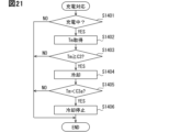
- FIG. 4 is a diagram for explaining a demagnetization region. 4 is a flowchart showing a procedure for flight control processing.
- 11 is a flowchart showing a procedure for a demagnetization response process.
- 10 is a flowchart showing the procedure of a second restricted range process.
- 11 is a flowchart showing the procedure of a restriction handling process.
- 11 is a flowchart showing a procedure of a maintenance process.
- 10 is a flowchart showing a procedure of a demagnetization response process in a second embodiment.
- FIG. 13 is a diagram for explaining the amount of deviation.
- FIG. 13 is a flowchart showing the procedure of a flight control process in a third embodiment.
- FIG. 4 is a diagram for explaining a demagnetization region.
- 13 is a flowchart showing the procedure of a flight control process in the fourth embodiment.
- 11 is a flowchart showing a procedure for a demagnetization response process.
- FIG. 13 is a block diagram showing the electrical configuration of a propulsion system according to a fifth embodiment.
- 4 is a flowchart showing a procedure for flight control processing.
- 4 is a flowchart showing the procedure for landing response processing.
- 5A and 5B are diagrams for explaining a first cooling threshold and a first stop threshold.
- 11 is a flowchart showing the procedure of a drive inspection process.
- 4 is a flowchart showing a procedure for takeoff preparation processing.
- 10 is a flowchart showing a procedure of a charging process.
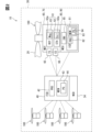
- the propulsion system 30 shown in FIG. 1 is mounted on the eVTOL 10.
- the eVTOL 10 is an electric vertical take-off and landing aircraft.
- the electric vertical take-off and landing aircraft is an electric vertical take-off and landing aircraft, and is capable of vertical take-off and landing.
- eVTOL is an abbreviation for electric Vertical Take-Off and Landing aircraft.
- the eVTOL 10 is an electric flying object that flies in the atmosphere, and may be referred to as an electric flying object.
- the eVTOL 10 is also an electric aircraft, and may be referred to as an electric aircraft.
- the eVTOL 10 is a manned flying object with a crew member on board.
- the crew member of the eVTOL 10 includes a pilot as a pilot or a driver.
- the propulsion system 30 is a system that drives the eVTOL 10 to propel it.
- the propulsion system 30 may be referred to as a flight system.
- the eVTOL 10 has an airframe 11 and a propeller 20.
- the airframe 11 has an airframe body 12 and wings 13.
- the airframe body 12 is the fuselage of the airframe 11 and has a shape that extends, for example, from front to back.
- the airframe body 12 has a passenger compartment 14 for passengers to ride in.
- the wings 13 extend from the airframe body 12 and multiple wings 13 are provided on the airframe body 12.
- the wings 13 are fixed wings.
- the multiple wings 13 include a main wing, a tail, etc.
- the eVTOL 10 has a cabin.
- the cabin is provided inside the eVTOL 10.
- the cabin is the internal space of the aircraft body 12, and is formed by the aircraft body 12.
- the cabin can be the crew compartment 14 or a cargo bay.
- the crew compartment 14 can be a passenger cabin or a pilot compartment.
- the crew compartment 14 is provided with seats for the crew to sit in.
- the crew compartment 14 does not have to have any crew on board, and may house cargo.
- the eVTOL 10 is a multicopter having at least three propellers 20.
- at least six propellers 20 are provided on the airframe 11.
- the propellers 20 are provided on each of the airframe body 12 and the wings 13.
- the propellers 20 rotate around a propeller axis.
- the propeller axis is, for example, the center line of the propeller 20.
- the propellers 20 are capable of generating thrust and lift for the eVTOL 10.
- the propellers 20 are sometimes referred to as rotors or rotating wings.
- propeller output includes the rotation speed and torque of the propellers 20.
- the propeller 20 has blades, a boss, and a propeller shaft.
- the blades are arranged in multiple rows circumferentially around the propeller axis.
- the boss connects the multiple blades.
- the propeller shaft is the rotation axis of the propeller 20, and extends from the boss along the propeller axis.
- Flight modes of the eVTOL 10 include vertical takeoff, vertical landing, cruise, hovering, etc. Flight modes are sometimes referred to as flight modes.
- vertical takeoff the eVTOL 10 can take off without running.
- vertical takeoff the eVTOL 10 can rise vertically or rise diagonally upward.
- vertical landing the eVTOL 10 can land without running.
- vertical landing the eVTOL 10 can descend vertically or descend diagonally downward.
- Cruise is sometimes referred to as horizontal flight.
- the eVTOL 10 may fly horizontally without moving vertically, or may fly horizontally while moving vertically. Hovering is sometimes referred to as stationary flight.
- hovering the eVTOL 10 may fly as if stopped at a predetermined position in the air, or the eVTOL 10 may deviate vertically or horizontally from the predetermined position.
- the flight modes of the eVTOL 10 include lift.
- the eVTOL 10 moves in an up and down direction.
- the eVTOL 10 may rise diagonally upward or descend diagonally downward.
- the eVTOL 10 takes off vertically by lifting upward.
- the eVTOL 10 lands vertically by lifting downward.
- the eVTOL 10 is a tilt rotor aircraft.
- the tilt angle of the propeller 20 is adjustable.
- one propeller 20 can function as both a lift propeller and a cruise propeller.
- the tilt angle is adjusted so that the propeller 20 functions as a lift rotor.
- the tilt angle is adjusted so that the propeller 20 functions as a cruise rotor.
- the eVTOL 10 does not have to be a tilt rotor aircraft.
- the eVTOL 10 may have a separate lift propeller 20 and a separate cruise propeller 20.
- the eVTOL 10 has a battery 31, a distributor 32, a communication unit 34, a flight control device 40, and an EPU 50.
- the battery 31, the distributor 32, the communication unit 34, the flight control device 40, and the EPU 50 are included in the propulsion system 30. Note that it is sufficient that the propulsion system 30 includes at least the flight control device 40 and the EPU 50.
- the flight control device 40 is sometimes referred to as a flight controller.
- the battery 31 is connected to the EPU 50 so that it can be electrically connected to it.
- the battery 31 is a power supply unit that supplies power to the EPU 50, and corresponds to a power supply unit.
- the battery 31 is a DC voltage source that applies a DC voltage to the EPU 50.
- the battery 31 has a secondary battery that can be charged and discharged. Examples of this secondary battery include a lithium ion battery and a nickel-metal hydride battery.
- the battery 31 is capable of storing power, and corresponds to a power storage device. Note that a fuel cell, a generator, or the like may be used as the power supply unit in addition to or instead of the battery 31.
- the distributor 32 is electrically connected to the battery 31 and the multiple EPUs 50.
- the distributor 32 distributes power from the battery 31 to the multiple EPUs 50.
- the battery 31 is electrically connected to the multiple EPUs 50 via the distributor 32.
- the battery 31 supplies power to the EPUs 50 via the distributor 32.
- the communication unit 34 is a communication device capable of wireless communication with an external device.
- the external device is a device located away from the eVTOL 10. Examples of external devices include communication devices installed in external facilities on the ground and communication devices installed in other flying objects. Examples of external facilities include a control center and a management center.
- the communication unit 34 is capable of communication with the flight control device 40.
- the communication unit 34 is connected to the flight control device 40 so that it can communicate via wired communication.
- the communication unit 34 may also be capable of wireless communication with the flight control device 40.
- the EPU 50 is a device that drives the propeller 20 to rotate, and corresponds to a drive device.
- EPU is an abbreviation for Electric Propulsion Unit.
- the EPU 50 is sometimes referred to as an electric drive device or an electric drive system.
- An EPU 50 is provided individually for each of the multiple propellers 20.
- the EPUs 50 are arranged on the propellers 20 along the propeller axis. All of the multiple EPUs 50 are fixed to the aircraft 11.
- the EPU 50 supports the propeller 20 so that it can rotate.
- the EPU 50 is connected to the propeller 20.
- the propeller 20 is fixed to the aircraft 11 via the EPU 50.
- the eVTOL 10 has a propulsion device 100.
- the propulsion device 100 is formed to include a propeller 20 and an EPU 50.
- the propulsion device 100 is a device for propelling the eVTOL 10.
- the propulsion device 100 causes the eVTOL 10 to fly by rotating the propeller 20.
- the eVTOL 10 is also a moving body that moves by the propulsion device 100.
- a plurality of propulsion devices 100 are provided in the eVTOL 10.
- One propulsion device 100 includes one each of a propeller 20 and an EPU 50 for driving the propeller 20. Of the propeller 20 and the EPU 50, only the EPU 50 may be referred to as the propulsion device 100.
- the EPU 50 has a motor device 60 and an inverter device 80.
- the motor device 60 has a motor 61 and a motor housing 70.
- the motor housing 70 is a housing and houses the motor 61.
- the motor 61 is a multi-phase AC motor.
- the motor 61 is a multi-phase AC rotating electric machine.
- the motor 61 is the flight drive source for the eVTOL 10 and functions as an electric motor.
- the motor 61 drives and rotates the propeller 20, enabling the eVTOL 10 to fly.
- the motor 61 is a flight motor for flying the eVTOL 10.
- the EPU 50 drives and rotates the propeller 20 by driving the motor 61.
- a brushless motor for example, is used as the motor 61.
- the motor 61 has a motor stator 62 and a motor rotor 63.
- the motor 61 has a motor stator 62.
- the motor stator 62 is a stator and is fixed to a motor housing 70.
- the motor rotor 63 rotates relative to the motor stator 62.
- the motor 61 is, for example, an axial gap type motor. In the motor 61, the motor stator 62 and the motor rotor 63 are aligned in the axial direction.
- the motor 61 has a motor shaft that rotates together with the motor rotor 63.
- the motor shaft is rotatably supported by the motor housing 70 or the like.
- the motor 61 is driven by supplying power to the motor stator 62.
- the motor stator 62 has a stator coil 62a.
- the stator coil 62a is a multi-phase coil.
- the stator coil 62a forms an armature.
- a current flows through the stator coil 62a, causing the motor rotor 63 to rotate.
- the motor rotor 63 has a rotor magnet 63a.
- the rotor magnet 63a forms a magnetic field.
- the rotor magnet 63a is a permanent magnet.
- the rotor magnet 63a is made of a rare earth magnet, a ferrite magnet, or the like.
- the rotor magnet 63a is made of a neodymium magnet.
- Thermal demagnetization can occur in the rotor magnet 63a. The higher the temperature of the rotor magnet 63a, the more likely the magnetic force of the rotor magnet 63a is to decrease due to thermal demagnetization.
- Reversible demagnetization and irreversible demagnetization can occur due to thermal demagnetization of the rotor magnet 63a.
- thermal demagnetization the magnetic force of the rotor magnet 63a decreases due to heat.
- reversible demagnetization occurs in the rotor magnet 63a due to thermal demagnetization, the higher the temperature of the rotor magnet 63a, the greater the amount of demagnetization due to reversible demagnetization.
- the motor output changes according to the magnetic force of the rotor magnet 63a.
- the motor output is a parameter that indicates the output of the motor 61.
- the motor output is the output torque of the motor 61.
- the output torque is the motor torque for rotating the motor rotor 63.
- the motor output is likely to decrease when the magnetic force of the rotor magnet 63a decreases.
- the motor output is likely to decrease as the irreversible demagnetization of the rotor magnet 63a progresses.
- the progression of irreversible demagnetization is sometimes referred to as the progression of deterioration.
- the motor device 60 is an air-cooled device.
- the motor device 60 has motor fins.
- the motor fins release heat from the motor device 60 to the outside air.
- the motor fins are heat dissipation fins and are included in the motor housing 70.
- the motor fins are provided on the outer surface of the motor housing 70.
- the inverter device 80 drives the motor device 60 by supplying power to the motor device 60.
- the inverter device 80 is a drive unit for driving the motor 61, and corresponds to a motor drive unit.
- the inverter device 80 has an inverter circuit 85 and an inverter housing 90.
- the inverter housing 90 is a housing and contains the inverter circuit 85.
- the inverter circuit 85 converts the power supplied to the motor 61.
- the inverter circuit 85 is sometimes referred to as an inverter, power conversion unit, or control circuit.
- the inverter circuit 85 performs power conversion for each of the multiple phases.
- the motor 61 drives according to the voltage and current supplied from the inverter circuit 85.
- the inverter device 80 is an air-cooled device.
- the inverter device 80 has inverter fins.
- the inverter fins release heat from the inverter device 80 to the outside air.
- the inverter fins are heat dissipation fins and are included in the inverter housing 90.
- the inverter fins are provided on the outer surface of the inverter housing 90.
- the propulsion device 100 is an air-cooled device.
- air cooling is possible using motor fins and inverter fins.
- a gas such as external air may flow into the interior of the propulsion device 100.
- the gas may pass through the interior of the motor housing 70 or the interior of the inverter housing 90.
- a gas such as air.
- the inverter device 80 has an inverter control unit 81.
- the inverter control unit 81 performs motor control via the inverter circuit 85.
- the motor control is control for driving the motor 61.
- the inverter control unit 81 also performs propulsion control.
- the propulsion control is control for driving the propulsion device 100.
- the propulsion control includes motor control.
- the propulsion control is also control for controlling the EPU 50, and is sometimes referred to as EPU control.
- the inverter control unit 81 has, for example, an ECU. ECU is an abbreviation for Electronic Control Unit.
- the inverter control unit 81 has a processor 82, a memory 83, and a program 84.
- the inverter control unit 81 is mainly composed of a computer. This computer has the processor 82, memory 83, an input/output interface, a bus connecting these, etc.
- the memory 83 stores the program 84.
- the program 84 is a program for performing propulsion control.
- the program 84 corresponds to a propulsion control program.
- the processor 82 is hardware for arithmetic processing coupled to the memory 83.
- the processor 82 executes various processes by accessing the memory 83.
- the memory 83 is a storage medium that stores a control program and the like.
- the memory 83 is a non-transitory tangible storage medium that non-temporarily stores computer-readable programs and data.
- the non-transitory tangible storage medium is a non-transitory tangible storage medium, and is realized by a semiconductor memory or a magnetic disk, for example.
- the program 84 includes computer-readable instructions that cause the processor 82 to execute various functions.
- the processor 82 is a processing unit that executes predetermined processes by executing instructions included in the program 84.
- the inverter control unit 81 controls the motor according to the required output.
- the required output is the motor output required of the inverter control unit 81.
- the required output includes the required torque required for the output torque.
- the required output is included in the command signal output by the flight control device 40 to the inverter control unit 81.
- the inverter control unit 81 adjusts the motor output according to the required output.
- the required output and the required torque are sometimes referred to as the target output and the target torque. Note that the motor output may be expressed as torque, current, voltage, motor rotation speed, etc.
- the inverter control unit 81 controls the motor using command signals from the flight control device 40 and detection signals from various sensors.
- the various sensors are communicatively connected to the inverter control unit 81.
- the various sensors include a motor sensor, a battery sensor, and an inverter sensor.
- the battery sensor is a temperature sensor or the like provided in the battery 31.
- the inverter sensor is a temperature sensor or the like provided in the inverter device 80.
- the motor sensors include a temperature sensor 65 and a current sensor 66.
- the temperature sensor 65 is provided in the motor device 60.
- the temperature sensor 65 detects the temperature of the motor 61.
- the temperature of the motor 61 includes the temperature of the rotor magnet 63a and the temperature of the stator coil 62a.
- the temperature sensor 65 can detect at least the temperature of the rotor magnet 63a.
- the temperature sensor 65 outputs a detection signal according to the temperature of the rotor magnet 63a.
- the temperature sensor 65 outputs a detection signal to the inverter control unit 81.
- the temperature sensor 65 may detect the temperature of the motor device 60, such as the motor housing 70.
- the current sensor 66 is provided in the motor device 60.
- the current sensor 66 detects the current flowing through the motor 61.
- the current sensor 66 detects the current flowing through the stator coil 62a.
- the current sensor 66 outputs a detection signal corresponding to the current flowing through the stator coil 62a.
- the current sensor 66 outputs the detection signal to the inverter control unit 81.
- the flight control device 40 is connected to the inverter control unit 81 so that they can communicate with each other.
- the flight control device 40 and the inverter control unit 81 may be capable of wireless communication.
- the flight control device 40 performs overall control to coordinate the drive of the multiple propulsion devices 100.
- the overall control coordinates the propulsion control performed by each of the multiple inverter control units 81.
- the flight control device 40 performs flight control.
- Flight control is control for flying the eVTOL 10.
- the flight control device 40 controls the propulsion system 30 and the EPU 50.
- Flight control is also control for propelling the eVTOL 10, and is sometimes referred to as propulsion control.
- the flight control device 40 corresponds to a propulsion control device.
- the flight control device 40 has, for example, an ECU.
- the flight control device 40 has a processor 42, a memory 43, and a program 44.
- the flight control device 40 is mainly composed of a computer. This computer has a processor 42, a memory 43, an input/output interface, a bus connecting these, etc.
- the memory 43 stores a program 44.
- the program 44 is a program for performing flight control.
- Processor 42 is hardware for arithmetic processing coupled to memory 43. Processor 42 executes various processes by accessing memory 43.
- Memory 43 is a storage medium that stores control programs and the like.
- Memory 43 is a non-transient tangible storage medium that non-temporarily stores computer-readable programs and data.
- Program 44 includes computer-readable instructions that cause processor 42 to execute various functions.
- Processor 42 is a processing unit that executes predetermined processes by executing instructions included in program 44.
- the flight control device 40 outputs information required for propulsion control to the inverter control unit 81.
- the flight control device 40 is a higher-level ECU for the inverter control unit 81.
- the flight control device 40 controls the multiple propulsion devices 100 individually according to the flight mode of the eVTOL 10, etc.
- the flight control device 40 can adjust the output of the propulsion devices 100 individually for each propulsion device 100.
- the flight control device 40 outputs a required output for each of the multiple propulsion devices 100.
- the required output is the output required of the propulsion device 100.
- the required output includes a required torque required for the motor 61. Note that the required output may be torque, current, voltage, propeller speed, etc.
- the flight control device 40 performs flight control according to the flight state of the eVTOL 10 and detection signals from various sensors.
- the flight state of the eVTOL 10 includes the flight mode and the flight attitude of the eVTOL 10.
- the various sensors are communicatively connected to the flight control device 40.
- the temperature sensor 65 and the current sensor 66 as various sensors are communicatively connected to both the inverter control unit 81 and the flight control device 40.
- the temperature sensor 65 and the current sensor 66 output detection signals to the flight control device 40.
- the temperature sensor 65 and the current sensor 66 may be directly connected to the flight control device 40, or may be indirectly connected to the flight control device 40 via the inverter control unit 81, etc.
- the flight control device 40 detects the motor temperature Tm using the detection signal of the temperature sensor 65.
- the motor temperature Tm is the temperature of the motor device 60.
- the motor temperature Tm is a temperature that corresponds to the magnet temperature.
- the magnet temperature is the temperature of the rotor magnet 63a. In this embodiment, the magnet temperature is detected as the motor temperature Tm.
- the flight control device 40 calculates the motor temperature Tm by correcting the detection signal of the temperature sensor 65 so that the temperature of the rotor magnet 63a can be detected as the motor temperature Tm.
- the flight control device 40 detects the motor current Im using the detection signal of the current sensor 66.
- the motor current Im is the current flowing through the motor 61.
- the motor current Im is the current flowing through the stator coil 62a.
- the flight control device 40 detects the motor current Im for at least one phase of the stator coil 62a. In motor control, the greater the torque required for the motor 61, the greater the motor current is likely to be. And the greater the motor current, the greater the output torque of the motor 61 is likely to be.
- the motor device 60 is shown as MOT, the motor stator 62 as STA, and the motor rotor 63 as ROT.
- the stator coil 62a is shown as Coil, the rotor magnet 63a as Mag, the temperature sensor 65 as TS, and the current sensor 66 as CS.
- the inverter device 80 is shown as MCU, the inverter circuit 85 as INV, and the inverter control unit 81 as ICD.
- the processor 82 is shown as PRO, the memory 83 as MEM, and the program 84 as PG.
- the flight control device 40 is shown as FCD, the processor 42 as PRO, the memory 43 as MEM, the program 44 as PG, and the communication unit 34 as WCD.
- the state of the rotor magnet 63a changes depending on the state of the motor 61.
- the state of the motor 61 changes depending on the motor temperature Tm and the motor current Im. For example, if the motor temperature Tm is too high, abnormalities in the rotor magnet 63a are likely to occur. Also, in a range in which the motor temperature Tm is not too high, no abnormalities in the rotor magnet 63a occur, but irreversible demagnetization of the rotor magnet 63a may occur. For example, in a range in which the motor temperature Tm is not too high, the greater the value of at least one of the motor temperature Tm and the motor current Im, the more likely irreversible demagnetization of the rotor magnet 63a is.
- irreversible demagnetization may be simply referred to as demagnetization.
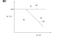
- multiple state regions are set for the motor temperature Tm and the motor current Im to indicate the state of the motor 61.
- the multiple state regions include an abnormal region A1, a demagnetization region A2, and a normal region A3.
- the abnormal region A1 is a region indicating that an abnormality in the rotor magnet 63a is likely to occur.
- the abnormal region A1 is also a region indicating that the motor temperature Tm has risen to a level corresponding to an abnormality in the rotor magnet 63a or the motor 61. If the state of the motor 61 continues to be in the abnormal region A1, there is a risk or possibility that an abnormality will occur in the rotor magnet 63a or the motor 61 even if the duration is short. Furthermore, the longer the duration, the higher the risk or possibility that an abnormality will occur in the rotor magnet 63a or the motor 61.
- the demagnetized area A2 and the normal area A3 are areas that indicate that the rotor magnet 63a is less likely to have an abnormality than the abnormal area A1.
- the demagnetized area A2 and the normal area A3 are areas that indicate that the rotor magnet 63a is normal, and are sometimes referred to as normal areas.
- the demagnetized area A2 and the normal area A3 are also areas that indicate that the motor temperature Tm has not risen to a level that corresponds to an abnormality in the rotor magnet 63a or the motor 61.
- the demagnetized area A2 and the normal area A3 are areas that are different from the abnormal area A1, and are areas that indicate that the motor temperature Tm is lower than the abnormal area A1.
- the normal region A3 is a region that does not correspond to an abnormality in the rotor magnet 63a and indicates that demagnetization of the rotor magnet 63a is less likely to occur than in the demagnetization region A2.
- demagnetization of the rotor magnet 63a hardly occurs.
- the demagnetization region A2 is a region that indicates that the rotor magnet 63a is likely to demagnetize, within a range that does not correspond to an abnormality of the rotor magnet 63a.
- the rotor magnet 63a is gradually demagnetized when the rotor magnet 63a is in the demagnetization region A2. For example, if the rotor magnet 63a is made of a neodymium magnet, the demagnetization of the neodymium magnet is likely to progress significantly when the motor 61 is in a high-temperature, high-current region such as the demagnetization region A2.
- the demagnetization cumulative time is the accumulated value of the time that the motor 61 is in the demagnetization region A2.
- the demagnetization cumulative time is the total value of all the time that the motor 61 is in the demagnetization region A2 after the eVTOL 10 is manufactured. The time that the motor 61 is in the abnormal region A1 or normal region A3 is not included in the demagnetization cumulative time.
- a first boundary line LB1 and a second boundary line LB2 exist for the abnormal region A1, the demagnetized region A2, and the normal region A3.
- the first boundary line LB1 indicates the boundary between the abnormal region A1 and the demagnetized region A2 and the normal region A3.
- the first boundary line LB1 indicates that the boundary between the abnormal region A1 and the normal region is the upper limit temperature TLB1.
- the upper limit temperature TLB1 is the upper limit value of the normal region.
- the first boundary line LB1 extends parallel to the axis of the motor current Im.
- the second boundary line LB2 indicates the boundary between the demagnetization region A2 and the normal region A3 in the normal region.
- the second boundary line LB2 extends so as to be inclined with respect to both the axis of the motor current Im and the axis of the motor temperature Tm.
- the second boundary line LB2 extends so that the state of the motor 61 is more likely to be included in the demagnetization region A2 the greater the value of at least one of the motor temperature Tm and the motor current Im.
- demagnetization of the rotor magnet 63a is likely to occur if the motor current Im is large even when the motor temperature Tm is low.
- demagnetization of the rotor magnet 63a is likely to occur if the motor temperature Tm is high even when the motor current Im is small.
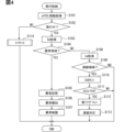
- the flight control device 40 performs flight control processing.
- the flight control processing will be explained with reference to the flowchart in FIG. 4.
- the flight control device 40 repeatedly executes the flight control processing at a predetermined control period.
- the flight control device 40 acquires eVTOL information in step S101.
- the eVTOL information is information that indicates the state of the eVTOL 10. Examples of the eVTOL information include information that indicates the flight state of the eVTOL 10 and information that indicates the state of each of the multiple propulsion devices 100. Information that indicates the state of the propulsion devices 100 includes detection signals from the temperature sensor 65 and the current sensor 66. Examples of the eVTOL information include information input from an external device to the flight control device 40 via the communication unit 34.
- step S102 the flight control device 40 determines whether the eVTOL 10 is in flight. For example, after the eVTOL 10 begins takeoff or before it has completed landing, it is determined that the eVTOL 10 is in flight. Also, while the eVTOL 10 is preparing for takeoff or after it has completed landing, it is determined that the eVTOL 10 is not in flight.
- the flight control device 40 executes the processing of steps S103 to S113 individually for each of the multiple propulsion devices 100.
- steps S103 to S111 that are executed for one propulsion device 100 are basically described. It is also assumed that the processing of steps S103 to S111 has been completed for the other propulsion devices 100.
- step S103 the flight control device 40 detects or calculates the motor temperature Tm.
- the motor temperature Tm is a parameter that indicates the driving state of the motor 61, and corresponds to the driving information.
- the function of the flight control device 40 that executes the processing of step S103 corresponds to the information acquisition unit.
- step S104 the flight control device 40 determines whether the state of the motor 61 is in the abnormal region A1. For example, the flight control device 40 determines whether the motor temperature Tm is higher than the upper limit temperature TLB1. If the motor temperature Tm is higher than the upper limit temperature TLB1, the flight control device 40 determines that the state of the motor 61 is in the abnormal region A1.
- the flight control device 40 performs abnormality response processing in steps S105 to S107.
- the abnormality response processing is processing for responding to an abnormality in the rotor magnet 63a.
- the flight control device 40 performs abnormality storage processing in step S105.
- processing is performed to store in the memory 43 or the like that the state of the motor 61 is in the abnormal region A1.
- the abnormality storage processing it is stored that the motor temperature Tm has risen to such an extent that it corresponds to an abnormality in the rotor magnet 63a or the motor 61.
- an abnormality flag is set in the management storage unit or the like.
- the abnormality flag is a flag for indicating that the state of the motor 61 is in the abnormal region A1.
- the management memory unit has volatile memory and non-volatile memory.
- volatile memory examples include RAM.
- RAM is an abbreviation for Random Access Memory.
- non-volatile memory examples include memories 43 and 83.
- Flags such as abnormality flags are stored in non-volatile memory. Memory data such as flags stored in the non-volatile memory of the management memory unit is not erased even if the power supply to eVTOL 10 is cut off, and remains in the management memory unit when the power supply to eVTOL 10 is turned on again. Flags such as abnormality flags may be stored in volatile memory such as RAM.
- the flight control device 40 performs an abnormality notification process in step S106.
- the abnormality notification process processing is performed to notify that the state of the motor 61 is in the abnormal region A1.
- the pilot or external facilities are notified that the motor temperature Tm has risen to such an extent that it corresponds to an abnormality in the rotor magnet 63a or the motor 61. Notification of various information is sometimes referred to as notifying various information.
- the flight control device 40 performs an abnormality limiting process in step S107.
- a process for limiting the motor current Im is performed.
- the motor temperature Tm decreases, and the state of the motor 61 is more likely to transition from the abnormal region A1 to the normal region.
- abnormalities in the rotor magnet 63a and the motor 61 are more likely to be resolved.
- the motor current Im is shut off.
- step S108 the flight control device 40 obtains the motor current Im by detection or calculation.
- the motor current Im is a parameter that indicates the driving state of the motor 61, and corresponds to the driving information.
- the function of the flight control device 40 that executes the processing of step S108 corresponds to the information acquisition unit.
- the flight control device 40 performs a management process to manage the demagnetization of the rotor magnet 63a in steps S109 to S113.
- the demagnetization state of the rotor magnet 63a is managed.
- the demagnetization state indicates the state of demagnetization of the rotor magnet 63a, such as whether or not demagnetization of the rotor magnet 63a has occurred.
- the demagnetization state includes the degree of demagnetization of the rotor magnet 63a.
- the degree of demagnetization indicates the extent to which the demagnetization of the rotor magnet 63a has progressed.
- the degree of demagnetization is sometimes referred to as the degree of deterioration of the rotor magnet 63a.
- the function that executes the processing of steps S109 to S113 in the flight control device 40 corresponds to the demagnetization management unit.
- step S109 the flight control device 40 determines whether the state of the motor 61 is in the demagnetization region A2.
- the motor temperature Tm and motor current Im are used for this determination.
- the flight control device 40 determines whether the current state of the motor 61 is in the demagnetization region A2.
- the motor temperature Tm and motor current Im acquired in steps S103 and S108 in the current flight control process are used as the current motor temperature Tm and motor current Im.
- step S110 the flight control device 40 counts the demagnetization counter Cd.
- the flight control device 40 adds a predetermined additional value to the demagnetization counter Cd.
- the additional value is sometimes called a count-up amount.
- the flight control device 40 sets the additional value to 1 and increments the demagnetization counter Cd by 1.
- the count value of the demagnetization counter Cd indicates the accumulated demagnetization time.
- the flight control device 40 obtains the degree of demagnetization of the rotor magnet 63a by counting the demagnetization counter Cd.
- the demagnetization counter Cd is set in the management memory unit.
- the demagnetization counter Cd may be counted as a RAM value of the management memory unit.
- the count value of the demagnetization counter Cd includes motor history information.
- the motor history information is information indicating the past state of the motor 61 as history.
- the motor history information is information indicating the history of the motor 61 with respect to past flight control processing executed before this time.
- the history of the motor 61 includes the history of the motor temperature Tm and the history of the motor current Im.
- the history of the motor temperature Tm includes information indicating that the motor temperature Tm is a temperature higher than the second boundary line LB2 when the state of the motor 61 is in the demagnetization region A2.
- the history of the motor current Im includes information indicating that the motor current Im is a current higher than the second boundary line LB2 when the state of the motor 61 is in the demagnetization region A2.
- the function of executing the processing of step S110 in the flight control device 40 corresponds to the history acquisition unit.
- the flight control device 40 manages the demagnetization of the rotor magnet 63a using the counter value of the demagnetization counter Cd.
- step S111 the flight control device 40 determines whether the demagnetization counter Cd has reached the counter threshold value TCd.
- the counter threshold value TCd is a value determined in advance through testing or the like, and is stored in the management memory unit.
- the counter threshold value TCd is a value that indicates that the demagnetization counter Cd has counted to a certain extent that the demagnetization of the rotor magnet 63a has progressed.
- step S109 the flight control device 40 determines whether the accumulated demagnetization time has reached the threshold time.
- step S109 the state of the motor 61 being in the demagnetization region A2 corresponds to a state in which the conditions for demagnetization of the rotor magnet 63a are met.
- step S110 the count value of the demagnetization counter Cd corresponds to the accumulated driving time of the motor 61 in a state in which the conditions for demagnetization of the rotor magnet 63a are met.
- step S111 the counter threshold value TCd corresponds to the threshold time.
- the function of the flight control device 40 that executes the processing of steps S109 to S111 corresponds to the accumulation determination unit.
- steps S109 to S113 the flight control device 40 manages the demagnetization of the rotor magnet 63a using the determination results of steps S109 to S111.
- step S109 if the state of the motor 61 is not in the demagnetization region A2, the flight control device 40 determines that demagnetization of the rotor magnet 63a is unlikely to occur and ends the flight control process. Also, in step S111, if the demagnetization counter Cd has not reached the counter threshold value TCd, the flight control device 40 determines that demagnetization of the rotor magnet 63a has not progressed much and ends the flight control process.
- step S112 the flight control device 40 sets a first flag in the management memory unit.
- the first flag is a flag indicating that the demagnetization counter Cd has reached the counter threshold value TCd.
- the first flag is a flag indicating that demagnetization of the rotor magnet 63a may have progressed to a certain extent.
- the flight control device 40 performs demagnetization response processing in step S113.
- the demagnetization response processing will be explained with reference to the flowchart shown in FIG. 5.
- the flight control device 40 determines whether the first flag is set.
- the flight control device 40 proceeds to step S202 and calculates the correction amount Ac.
- the flight control device 40 performs motor control for the motor 61 so that the motor output, such as the output torque, becomes the target output, such as the target torque.
- the motor control feedback control, learning control, etc. are performed on the motor current Im so that the motor output becomes the target output.
- the correction amount Ac is calculated so that the motor output becomes the target output, and the correction amount Ac is used to control the motor current Im.
- the target current is calculated using the target output, and the target current is corrected with the correction amount Ac to control the motor current Im.
- the target current is a target value of the motor current Im, and is calculated according to the target output using a map, an arithmetic expression, etc.
- the motor output is calculated using the motor current Im, etc.
- the motor output corresponds to the output value
- the target output corresponds to the target value.
- the target current is sometimes called the control initial value.
- step S203 the flight control device 40 determines whether the correction amount Ac is equal to or greater than the correction threshold value TAc.
- the correction threshold value TAc is a value determined in advance by testing or the like, and is stored in the memory 43 or the like. Determining whether the correction amount Ac is equal to or greater than the correction threshold value TAc corresponds to determining whether the correction amount Ac is excessive, and determining whether the magnetic force deficiency condition for the rotor magnet 63a is satisfied.
- the deficiency condition is a condition that indicates a magnetic force deficiency due to the progress of demagnetization for the rotor magnet 63a.
- the correction amount Ac being equal to or greater than the correction threshold value TAc corresponds to the correction amount Ac being excessive, and the magnetic force deficiency condition for the rotor magnet 63a being satisfied.
- the function of executing the processing of step S203 in the flight control device 40 corresponds to the correction determination unit and the progress determination unit.
- the flight control device 40 proceeds to step S204 and sets a second flag in the management memory unit.
- the second flag is a flag indicating that the correction amount Ac is equal to or greater than the correction threshold value TAc.
- the second flag is a flag indicating that demagnetization of the rotor magnet 63a has progressed to a certain extent.
- step S205 the flight control device 40 performs second limit range processing.
- the second limit range processing is processing for adjusting the limit range for limiting the motor current Im in accordance with the motor temperature Tm.
- the degree of limiting the motor current Im is adjusted.
- a current limit value for limiting the maximum value of the motor current Im is set.
- the current limit value is set to a value according to the degree of limiting the motor current Im. The greater the degree of limiting the motor current Im, the smaller the current limit value is set to.
- the current limit value is set with respect to the target current.
- the current limit value limits the maximum value of the motor current Im by limiting the maximum value of the target current.
- a current limit value is set for the motor current Im, and the motor output and output torque are limited by the current limit value.
- an output limit value for limiting the motor output and a torque limit value for limiting the output torque may also be set. Even in a configuration in which an output limit value and a torque limit value are set, the motor current Im is still limited.
- the second restricted range processing will be described with reference to the flowchart shown in FIG. 6.
- the flight control device 40 determines which of multiple temperature ranges the motor temperature Tm is included in.
- the multiple temperature ranges include a low range, a medium range, and a high range.
- the low range is a range of temperatures lower than the medium range.
- the high range is a range of temperatures higher than the medium range.
- step S301 the flight control device 40 determines whether the motor temperature Tm is lower than the first temperature threshold T1.
- the first temperature threshold T1 is a value determined in advance through testing or the like, and is stored in the memory 43 or the like.
- the flight control device 40 determines whether the motor temperature Tm is in the low range by determining whether the motor temperature Tm is lower than the first temperature threshold T1. If the motor temperature Tm is lower than the first temperature threshold T1, the flight control device 40 determines that the motor temperature Tm is in the low range.
- the flight control device 40 determines in step S302 whether the motor temperature Tm is lower than the second temperature threshold T2.
- the second temperature threshold T2 is set to a value higher than the first temperature threshold T1.
- the second temperature threshold T2 is a value determined in advance through testing or the like, and is stored in the memory 43 or the like. If the motor temperature Tm is equal to or higher than the first temperature threshold T1, the flight control device 40 determines whether the motor temperature Tm is in the intermediate range by determining whether the motor temperature Tm is lower than the second temperature threshold T2. If the motor temperature Tm is equal to or higher than the first temperature threshold T1 and lower than the second temperature threshold T2, the flight control device 40 determines that the motor temperature Tm is in the intermediate range.
- the flight control device 40 proceeds to step S303 and performs low range processing.
- low range processing the degree of limitation of the motor current Im is adjusted in accordance with the fact that the motor temperature Tm is in the low range.
- the degree of limitation of the motor current Im is set to a looser value.
- the degree of limitation is set so that the motor current Im is not limited.
- the flight control device 40 sets the current limit value to the maximum output value for the motor current Im.
- the maximum output value is the maximum value of the motor current Im in the range that the motor 61 can output.
- the maximum output value is a value determined according to the rated output of the motor 61.
- the flight control device 40 may not set a current limit value so that the motor current Im is not limited.
- the flight control device 40 proceeds to step S304 and performs intermediate range processing.
- intermediate range processing the degree of limitation of the motor current Im is set in accordance with the fact that the motor temperature Tm is in the intermediate range.
- the degree of limitation of the motor current Im in intermediate range processing is set to be stricter than the degree of limitation of the motor current Im in low range processing.
- the degree of limitation is set so that the motor current Im is limited.
- the flight control device 40 sets the current limit value to a value smaller than the maximum output value for the motor current Im and larger than zero.
- the current limit value is set to a value such as 50% of the maximum output value.
- the current limit value may be variably set according to the motor temperature Tm within a range smaller than the maximum output value and larger than zero.
- the flight control device 40 proceeds to step S305 and performs higher range processing.
- the degree of limitation of the motor current Im is set in accordance with the fact that the motor temperature Tm is in the higher range.
- the degree of limitation of the motor current Im in higher range processing is set to be stricter than the degree of limitation of the motor current Im in intermediate range processing. For example, in higher range processing, the degree of limitation is set so that the motor current Im is cut off. In this case, the flight control device 40 sets the current limit value to zero. In other words, the flight control device 40 sets the current limit value so that the drive of the motor 61 is stopped.
- the flight control device 40 determines whether or not restricted flight of the eVTOL 10 is possible in step S206.
- Restricted flight refers to flight of the eVTOL 10 with the motor current Im restricted to the current limit value.
- a case in which restricted flight of the eVTOL 10 is possible is when the target current for the motor current Im is smaller than the current limit value. In this case, even if the current limit value is set, the motor current Im is not restricted by the current limit value, so restricted flight of the eVTOL 10 is possible.
- Another case in which restricted flight of the eVTOL 10 is possible is when flight of the eVTOL 10 is possible by driving another propulsion device 100 for which the second flag is not set. In this case, the flight control device 40 performs processing for restricted flight of the eVTOL 10, such as processing for changing the target output and target torque for the other propulsion device 100.
- the second limiting process is a process for limiting the motor current Im.
- motor control is performed in a state in which the motor current Im is limited by the current limiting value.
- the flight control device 40 adjusts the degree of limiting the motor current Im according to the motor temperature Tm using the current limiting value set in the above step S205.
- the flight control device 40 can limit the motor current Im by performing the second limiting process when the magnetic force deficiency condition is satisfied for the rotor magnet 63a.
- the function of executing the processes of steps S205 and S207 in the flight control device 40 corresponds to the temperature response unit and the current limiting unit.
- the flight control device 40 limits the motor current Im using the current limiting value set in step S303 above.
- the current limiting value is set to the maximum output value, so that the motor current Im is not limited by the current limiting value. For this reason, the flight control device 40 does not limit the motor current Im in steps S207 and S303.
- the function of the flight control device 40 that executes the processing of steps S207 and S303 corresponds to the non-limiting section.
- the flight control device 40 limits the motor current Im using the current limit value set in step S304 above.
- the current limit value is set to a value smaller than the maximum output value and greater than zero. Therefore, in steps S207 and S304, the flight control device 40 limits the motor current Im using the current limit value so as not to cut it off.
- the function of the flight control device 40 to execute the processing of steps S207 and S304 corresponds to the specific limiting unit.
- the flight control device 40 limits the motor current Im using the current limit value set in step S305 above. In this case, the current limit value is set to zero. Therefore, in steps S207 and S305, the flight control device 40 cuts off the motor current Im so that the motor current Im does not flow.
- the function of the flight control device 40 that executes the processes of S207 and S305 corresponds to the current cutoff unit.
- the current limit value is set according to the motor temperature Tm.
- the flight control device 40 selects which of the above steps S303 to S305 to set the current limit value according to the motor current Im in steps S301 and S302.
- the flight control device 40 also selects the non-limiting section, the current limiting section, and the current interrupting section according to the motor temperature Tm.
- the function of the flight control device 40 that executes the processing of steps S301 and S302 corresponds to the limit selection section.
- the flight control device 40 proceeds to step S215 and performs demagnetization notification process.
- demagnetization notification process demagnetization information of the rotor magnet 63a is notified via the communication unit 34, etc. For example, the demagnetization information is notified to a pilot or an external device. The demagnetization information is also stored in the memory 43, etc. The demagnetization information is notified to an operator or a maintenance device via the memory 43, etc.
- the demagnetization information is information related to the demagnetization of the rotor magnet 63a.
- the demagnetization information includes information indicating the demagnetization state and degree of demagnetization of the rotor magnet 63a. In the demagnetization notification process, it is notified that the current state of the motor 61 is in the demagnetization region A2, that the accumulated demagnetization time has reached the threshold time, etc.
- the demagnetization notification process When proceeding to step S215 after step S207 as in this case, the demagnetization notification process notifies that the correction amount Ac is equal to or greater than the correction threshold value TAc. In other words, the demagnetization notification process notifies that the magnetic force deficiency condition is met for the rotor magnet 63a.
- the function of executing the process of step S215 in the flight control device 40 corresponds to the notification execution unit. Furthermore, the demagnetization notification process notifies that the eVTOL 10 is capable of restricted flight, that the second restriction process has been executed, and so on. Regarding the second restriction process, it notifies whether the motor temperature Tm is in the low range, medium range, or high range, and so on.
- step S215 the flight control device 40 proceeds to step S216 and performs restriction response processing.
- restriction response processing will be explained later.
- step S208 the flight control device 40 sets a third flag in the management memory unit.
- the third flag is a flag indicating that the correction amount Ac is equal to or greater than the correction threshold value TAc and restricted flight of the eVTOL 10 is not possible.
- the third flag is also a flag indicating that the second restriction process is not to be executed when the second flag is set.
- the flight control device 40 performs a second mitigation process in step S209.
- the second mitigation process is a process for prioritizing the flight of the eVTOL 10 over the limitation of the motor current Im.
- the limitation of the motor current Im is relaxed. That is, in the second mitigation process, the degree of limitation of the motor current Im is set lower.
- the degree of limitation of the motor current Im is adjusted so that the limitation of the motor current Im is relaxed compared to the second limitation process in step S207 above.
- the second mitigation process is a process for temporarily mitigating the limitation of the motor current Im, on the premise that appropriate measures will be reliably taken during maintenance, which will be described later, after the eVTOL 10 has landed at a destination, etc.
- the fact that limited flight of the eVTOL 10 is not possible corresponds to the fact that the motor current Im is insufficient for propulsion of the eVTOL 10 when the second limiting process limits the motor current Im.
- the function of executing the process of step S209 in the flight control device 40 corresponds to the limit relaxation section.
- the motor current Im is limited so that the limit on the motor current Im is relaxed compared to the second restriction process.
- the flight control device 40 does not limit the motor current Im as in step S303 above, and also relaxes the correction limit on the correction amount Ac.
- a correction amount range is set to limit the magnitude of the correction amount Ac.
- the correction amount Ac is not set to a value that exceeds the correction amount range.
- the correction amount Ac is set to a value that is equal to or less than the upper limit value of the correction amount range and equal to or greater than the lower limit value of the correction amount range.
- the correction amount range is set based on the magnitude of the target current.
- the upper limit of the correction amount range is set to +20% of the target current
- the lower limit is set to -20% of the target current.
- the flight control device 40 performs a process to widen the correction amount range as a relaxation of the correction amount range. In this process, at least one of the upper limit and lower limit of the correction amount range is changed. For example, the flight control device 40 changes the upper limit of the correction amount range to +40% of the target current. Meanwhile, the lower limit of the correction amount range is maintained as -20% of the target current.
- the flight control device 40 does not limit the motor current Im, as in step S303 above. Therefore, in the second mitigation process, when the motor temperature Tm is in the intermediate range, the same process as in step S303 above is performed, rather than the same process as in step S304 above, thereby mitigating the limit on the motor current Im.
- the flight control device 40 limits the motor current Im with a current limit value so as not to cut off the motor current Im, as in step S304 above. Therefore, in the second mitigation process, when the motor temperature Tm is in the higher range, the same process as in step S304 above is performed, rather than the same process as in step S305 above, thereby mitigating the limit on the motor current Im.
- the flight control device 40 sets a prohibition flag in the management memory unit in step S210.
- the prohibition flag is a flag for prohibiting the eVTOL 10 from taking off again.
- a retake is when the eVTOL 10 takes off again after landing at a destination or the like and ending the current flight.
- the prohibition flag is also a flag for restricting takeoff, such as a retake, of the eVTOL 10.
- the flight control device 40 restricts the takeoff of the eVTOL 10 when the magnetic force deficiency condition is met for the rotor magnet 63a.
- the function of the flight control device 40 that executes the processing of step S210 corresponds to the takeoff restriction unit.
- the flight control device 40 performs prohibition processing to prohibit the eVTOL 10 from taking off again.
- the prohibition processing includes setting a prohibition flag. Examples of prohibition processing include processing to restrict operations for re-taking off the eVTOL 10 and processing to restrict the propulsion device 100 from operating to re-taking off the eVTOL 10.
- the prohibition processing can restrict the eVTOL 10 from taking off again.
- the prohibition processing is sometimes referred to as a restriction processing.
- the flight control device 40 After performing the second mitigation process and setting the prohibition flag, the flight control device 40 proceeds to step S215 and performs the demagnetization notification process.
- the demagnetization notification process notifies that the magnetic force deficiency condition is met for the rotor magnet 63a, just as when proceeding to step S215 after step S207.
- this demagnetization notification process notifies that the eVTOL 10 is not capable of restricted flight and that the second mitigation process has been performed.
- the second mitigation process notifies whether the motor temperature Tm is in the low, medium, or high range.
- this demagnetization notification process notifies that re-takeoff of the eVTOL 10 is restricted.
- step S215 the flight control device 40 performs restriction response processing in step S216.
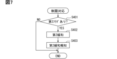
- the restriction response processing will be described with reference to the flowchart shown in FIG. 7.
- step S401 shown in FIG. 7 the flight control device 40 determines whether or not the third flag is set. When the third flag is set, there are cases where the process proceeds to step S216 after it is determined in step S206 that the eVTOL 10 is capable of restricted flight, and cases where the process proceeds to step S216 after it is determined that the eVTOL 10 is not capable of restricted flight.
- step S206 The result of the determination in step S206 as to whether or not the eVTOL 10 is capable of restricted flight may change depending on the flight state of the eVTOL 10. For this reason, the increase or decrease in the target output and target current depending on the flight state of the eVTOL 10 is reflected in the result of the determination as to whether or not the eVTOL 10 is capable of restricted flight. For example, even if the previous flight control process determined that the eVTOL 10 was not capable of restricted flight and the third flag was set, the current flight control process may determine that the eVTOL 10 is capable of restricted flight and perform the second restriction process.
- step S402 the flight control device 40 performs the second mitigation process in the same manner as in step S209 above. In this way, even if step S206 in the current flight control process determines that the eVTOL 10 is capable of restricted flight, the flight control device 40 performs the second mitigation process if the third flag is set.
- the function of the flight control device 40 that executes the process of step S402 corresponds to the restriction mitigation unit.
- the flight control device 40 performs the second mitigation notification process in step S403.
- the second mitigation notification process it is notified that the third flag has been set, that the second mitigation notification process will be performed even if the eVTOL 10 is capable of restricted flight, etc.
- the second mitigation notification process it is notified that the magnetic force deficiency condition is met for the rotor magnet 63a, similar to the demagnetization notification process.
- the function of executing the process of step S403 in the flight control device 40 corresponds to the notification execution unit.
- step S402 If there is no third flag in step S402, the flight control device 40 ends this restriction response process as is. In this case, the flight control device 40 ends this flight control process as is.
- a case in which there is no third flag is when the second mitigation process has never been performed in step S209 during the flight of the eVTOL 10.
- step S203 if the correction amount Ac is not equal to or greater than the correction threshold value TAc, the flight control device 40 proceeds to step S211.
- the flight control device 40 performs a first limit range process in step S211.
- the first limit range process is a process for adjusting the limit range of the motor current Im.
- the first limit range process is a process for adjusting the limit range of the motor current Im so as to relax the limit on the motor current Im compared to the second limit range process.
- the degree of limitation on the motor current Im is adjusted according to the motor temperature Tm.
- step S212 the flight control device 40 determines whether the eVTOL 10 is capable of limited flight, similar to step S206 above. If the eVTOL 10 is capable of limited flight, the flight control device 40 proceeds to step S213 and performs a first limiting process.
- the first limiting process is a process for limiting the motor current Im.
- the flight control device 40 adjusts the degree of limiting the motor current Im according to the motor temperature Tm, using the current limit value set in step S211 above. In the first limiting process, the motor current Im is limited so as to relax the limit on the motor current Im compared to the second limiting process.
- the flight control device 40 proceeds to step S215 and performs the demagnetization notification process.
- the demagnetization notification process notifies that the correction amount Ac is not equal to or greater than the correction threshold value TAc. In other words, this demagnetization notification process notifies that the magnetic force deficiency condition is not met for the rotor magnet 63a.
- This demagnetization notification process also notifies that the eVTOL 10 is capable of restricted flight, that the first restriction process has been performed, and so on.
- the first mitigation process is a process for prioritizing flight of the eVTOL 10 over the limitation of the motor current Im.
- the limitation of the motor current Im is relaxed. That is, in the first mitigation process, the degree of limitation of the motor current Im is set to a low level.
- the degree of limitation of the motor current Im is adjusted so that the limitation is relaxed compared to the first limitation process in step S213 above.
- the degree of limitation of the motor current Im is adjusted so that the limitation is relaxed compared to the second mitigation process in step S209 above.
- the motor current Im is not limited regardless of the motor temperature Tm.
- the flight control device 40 proceeds to step S215 and performs the demagnetization notification process.
- the demagnetization notification process notifies the user that the magnetic force deficiency condition is not met for the rotor magnet 63a.
- the current demagnetization notification process also notifies the user that the eVTOL 10 is not capable of restricted flight, that the first mitigation process has been performed, and so on.
- step S114 the flight control device 40 performs maintenance processing in step S114.
- the maintenance processing is performed when the eVTOL 10 is not flying, such as after the eVTOL 10 lands or before takeoff. The maintenance processing will be described with reference to the flowchart shown in FIG. 8.
- step S501 shown in FIG. 8 the flight control device 40 determines whether or not a reset process has been requested.
- the reset process is a process for resetting various flags, etc. Examples of the various flags include an abnormality flag and a first flag.
- the flight control device 40 determines whether or not a reset request for a reset process has been input.
- a reset request is input to the flight control device 40 when an operator such as a pilot operates an operating unit of a maintenance device, etc.
- a reset request is input to the flight control device 40 from an appropriate tool such as a maintenance device only when an operator performs an operation for a reset request using an appropriate tool or procedure. If a reset request is input to the flight control device 40, the flight control device 40 determines that the reset process should be performed and proceeds to step S502.
- step S502 the flight control device 40 determines whether or not maintenance has been performed on the eVTOL 10.
- the flight control device 40 determines whether or not a maintenance record indicating that maintenance has been performed is stored in the management memory unit.
- the maintenance record is a record indicating that maintenance was performed after the flight of the eVTOL 10 was completed.
- the maintenance device or the like stores the maintenance record in the management memory unit. Maintenance includes work to service the eVTOL 10, work to inspect the eVTOL 10, work to replace parts of the eVTOL 10, etc.
- step S503 the flight control device 40 performs a reset process in step S503.
- various flags and the like are reset. For example, in the reset process, flags set in the management memory unit among the various flags are cleared to an initial value such as zero.
- the demagnetization counter Cd may be reset.
- the reset request includes a request to reset the demagnetization counter Cd.
- the demagnetization counter Cd is reset.
- the demagnetization counter Cd is reset by clearing its counter value to an initial value such as zero.
- the management memory unit is capable of setting various flags and demagnetization counters Cd in states corresponding to each of the multiple propulsion devices 100.
- the management memory unit is also capable of setting various flags and demagnetization counters Cd in states corresponding to each of the multiple motors 61.
- the management memory unit be capable of setting multiple flags and demagnetization counters Cd for one propulsion device 100.
- the flight control device 40 performs a reset notification process in step S504.
- reset information indicating that various flags, etc. have been reset is notified to an operator or an external device.
- the reset information includes information indicating which of the various flags has been reset, information indicating whether the demagnetization counter Cd has been reset, etc.
- step S505 If maintenance has not been performed in step S502, the flight control device 40 proceeds to step S505.
- the flight control device 40 performs a reset prohibition process in step S505.
- the reset prohibition process is a process for prohibiting various flags, the demagnetization counter Cd, etc. from being reset.
- the flight control device 40 performs a prohibition notification process in step S506.
- the prohibition notification process reset prohibition information indicating that resetting of various flags, the demagnetization counter Cd, etc. is prohibited is notified to the operator or an external device.
- the reset prohibition information includes information such as the fact that maintenance has not been performed and the type of flag set in the management memory unit.
- the flight control device 40 manages the demagnetization of the rotor magnet 63a using drive information such as the motor temperature Tm and the motor current Im.
- drive information such as the motor temperature Tm and the motor current Im.
- the first and second limiting processes prevent the motor 61 from reaching a state of high temperature and high current.
- the first and second limiting processes make it difficult for demagnetization of the rotor magnet 63a to occur, preventing a decrease in performance of the motor 61.
- the first and second limiting processes can prevent the motor temperature Tm from becoming so high that it would be considered an abnormality in the motor 61.
- Tm motor temperature
- the mounting ability of the motor 61 will deteriorate and the weight and cost will increase as the size and cooling effect of the motor 61 increase.
- it is possible to improve the cooling effect by making the motor device 60 a liquid-cooled device.
- the motor current Im is limited by the first limiting process and the second limiting process, making it possible to avoid such a condition. Therefore, demagnetization of the rotor magnet 63a can be suppressed without increasing the output or cooling effect of the motor 61. Therefore, there is no need to increase the size, weight, or cost of the motor device 60 in order to suppress demagnetization of the rotor magnet 63a.
- the motor 61 In the eVTOL 10 as a manned aircraft, there is a strong demand for the motor 61 to be lightweight, while at the same time requiring high output of several tens to several hundreds of kW. In other words, there is a demand to increase the output density of the motor 61. In the motor 61, the higher the output density, the higher the motor temperature Tm tends to become. As the motor temperature Tm rises, the rotor magnet 63a becomes more susceptible to demagnetization. For this reason, a configuration in which the motor current Im is limited in a state in which the rotor magnet 63a is susceptible to demagnetization, as in this embodiment, is effective in suppressing demagnetization of the rotor magnet 63a in a manned aircraft.
- the flight control device 40 manages the demagnetization of the rotor magnet 63a using motor history information such as the demagnetization counter Cd.
- motor history information such as the demagnetization counter Cd.
- the flight control device 40 manages the demagnetization of the rotor magnet 63a using the result of the determination of whether the demagnetization counter Cd has reached the counter threshold value TCd. Since this determination result reflects the degree of demagnetization of the rotor magnet 63a, the flight control device 40 can manage the demagnetization state of the rotor magnet 63a by, for example, limiting the motor current Im according to the degree of demagnetization of the rotor magnet 63a. For example, when the demagnetization counter Cd has not reached the counter threshold value TCd, the motor current Im is not limited, thereby preventing a shortage of motor output. Furthermore, when the demagnetization counter Cd has reached the counter threshold value TCd, the demagnetization of the rotor magnet 63a can be prevented by limiting the motor current Im using the first limiting process or the second limiting process.
- the correction amount Ac is equal to or greater than the correction threshold value TAc, it is determined that the magnetic force deficiency condition is met for the rotor magnet 63a, and the motor current Im is limited by the second limiting process.
- the demagnetization of the rotor magnet 63a has progressed to the point where the magnetic force deficiency condition is met, further progression of the demagnetization can be prevented by limiting the motor current Im.
- the higher the motor temperature Tm the more likely demagnetization of the rotor magnet 63a occurs. For example, if the current motor temperature Tm is sufficiently low, the rotor magnet 63a is less likely to be demagnetized even if the motor current Im is large. For this reason, even if the correction amount Ac is equal to or greater than the correction threshold value TAc, if the current motor temperature Tm is low, the rotor magnet 63a is less likely to be demagnetized further.
- the flight control device 40 adjusts the degree of limitation of the motor current Im by the second limitation process according to the motor temperature Tm.
- the motor current Im can be adjusted according to the likelihood of demagnetization of the rotor magnet 63a.
- the demagnetization of the rotor magnet 63a can be more appropriately managed. For example, when the motor temperature Tm is low and demagnetization of the rotor magnet 63a is unlikely to occur, it is possible to prioritize preventing a shortage of the motor current Im over suppressing the demagnetization of the rotor magnet 63a. Also, when the motor temperature Tm is high and demagnetization of the rotor magnet 63a is likely to occur, it is possible to prioritize suppressing demagnetization of the rotor magnet 63a over ensuring the motor current Im.
- low range processing, intermediate range processing, and high range processing are selected according to the motor temperature Tm.
- the motor current Im is not limited
- the motor current Im is limited so as not to be cut off
- the motor current Im is cut off. Therefore, a configuration can be realized in which multiple stages of current limiting are applied to the motor current Im according to the motor temperature Tm.
- the current limiting is strict in the high temperature range where the motor temperature Tm is easily demagnetized, is not limited in the low temperature range where demagnetization is difficult, and is loosened in the intermediate range where demagnetization does not occur as much as in the high temperature range, so that the demagnetization of the rotor magnet 63a can be appropriately managed.
- the motor output such as the motor current Im
- the correction amount Ac is set to an excessively large value to compensate for this shortfall.
- the correction amount Ac is so excessive that it is equal to or greater than the correction threshold value TAc, the magnetic force deficiency condition for the rotor magnet 63a is met.
- the demagnetization notification process notifies the pilot, etc. that the correction amount Ac is equal to or greater than the correction threshold value TAc. For example, when the correction amount Ac is equal to or greater than the correction threshold value TAc, demagnetization information is stored and transmitted so that inspection or replacement can be performed before the demagnetization of the rotor magnet 63a progresses further.
- the limit on the motor current Im is relaxed by the second mitigation unit.
- priority can be given to ensuring that the motor current Im is not insufficient for propulsion of the eVTOL 10, rather than suppressing demagnetization of the rotor magnet 63a. Therefore, it is possible to achieve an appropriate balance between suppressing demagnetization of the rotor magnet 63a and ensuring the safety of the eVTOL 10.
- the flight control device 40 notifies the pilot or the like that a magnetic insufficiency condition is met for the rotor magnet 63a by a demagnetization notification process or the like.
- a demagnetization notification process or the like it is possible to notify the pilot or the like of the magnetic insufficiency of the rotor magnet 63a before the demagnetization of the rotor magnet 63a progresses to the point where an abnormality or performance degradation of the motor 61 occurs. Therefore, by performing inspections or part checks on the rotor magnet 63a before the motor 61 reaches an abnormality or performance degradation, it is possible to prevent the occurrence of an abnormality or performance degradation of the motor 61.
- the flight control device 40 restricts the takeoff of the eVTOL 10 when the magnetic force deficiency condition is met for the rotor magnet 63a. This makes it possible to avoid a situation in which the eVTOL 10 takes off again without maintenance of the motor 61 being performed, even though the magnetic force of the rotor magnet 63a is insufficient. This makes it possible to reliably prevent the safety of the eVTOL 10 from being reduced due to the magnetic force deficiency of the rotor magnet 63a.
- an abnormal region A1 and a demagnetization region A2 are set according to the motor temperature Tm as regions indicating the state of the motor 61.
- the abnormal region A1 has a temperature condition for the motor temperature Tm that quickly limits the motor current Im.
- the demagnetization region A2 has a temperature condition for the motor temperature Tm for determining demagnetization that is lower than the temperature condition of the abnormal region A1.
- the motor current Im is quickly limited by the abnormality limiting process. This makes it possible to prevent the output of the propulsion device 100 from being unintentionally insufficient due to the state of the motor 61 being in the abnormal region A1.
- the progress of demagnetization in the rotor magnet 63a can be monitored by determining whether the state of the motor 61 is in the abnormal region A1, the demagnetization region A2, or the normal region A3. This makes it possible to accept the risk that the demagnetization of the rotor magnet 63a will progress to a certain extent as the motor 61 is driven, while taking measures such as replacing parts before the demagnetization of the rotor magnet 63a actually affects the flight of the eVTOL 10.
- the demagnetization of the rotor magnet 63a is managed in accordance with the change in the correction amount Ac.
- the configurations, actions, and effects of the second embodiment that are not specifically described are the same as those of the first embodiment.
- the second embodiment will be described mainly with respect to the differences from the first embodiment.
- the flight control device 40 performs flight control processing in the same manner as in the first embodiment described above.
- the demagnetization response processing of the flight control processing will be described with reference to the flowchart in FIG. 9.
- the flight control device 40 performs the processing of steps S201 to S216 in the same manner as in the first embodiment described above.
- the flight control device 40 performs the processing of steps S601 and S602.
- the flight control device 40 calculates the smoothing value Sm in step S601.
- the smoothing value Sm is a value for smoothing the correction amount Ac.
- the smoothing value Sm is a value that smoothes the change in the correction amount Ac.
- the smoothing value Sm is calculated using Equation 1.
- Sm[t] ⁇ Ac[t]+(1- ⁇ ) ⁇ Sm[t-1]...Formula 1
- ⁇ is a value greater than zero and less than 1. That is, 0 ⁇ 1.
- [t] is the value acquired in the current demagnetization response process.
- [t-1] is the value acquired in the previous demagnetization response process.
- Sm[t] is the smoothing value Sm calculated in step S610 this time.
- Sm[t- 1] is the smoothing value Sm calculated in the previous step S601.
- Ac[t] is the correction amount Ac calculated in the current step S202.
- the smoothing value Sm is calculated based on the learning control Alternatively, the circumference value calculated by the following formula may be used.
- the smoothing value line LSm changes more gradually than the correction amount line LAC.
- the smoothing value line LSm is a line that shows the change in the smoothing value Sm.
- the correction amount line LAC is a line that shows the change in the correction amount Ac.
- the correction amount Ac is equal to or greater than the correction threshold value TAc.
- the flight control device 40 determines whether or not the sudden flag is set.
- the sudden flag is a flag that indicates that a sudden abnormality has occurred.
- a sudden abnormality is an abnormality that occurs suddenly, such as one that is accompanied by a sudden change in the correction amount Ac. Examples of sudden abnormalities include abnormalities that occur when a foreign object gets caught in the motor shaft or propeller shaft. Even if an abnormality occurs in the rotor magnet 63a or the motor 61 as the demagnetization of the rotor magnet 63a progresses, this abnormality is not included in the sudden abnormality. In other words, the sudden abnormality is not an abnormality caused by the demagnetization of the rotor magnet 63a.
- step S603 the flight control device 40 determines whether or not there is a deviation between the smoothing value Sm and the correction amount Ac. For example, the flight control device 40 determines whether or not the deviation amount Dt is greater than the deviation threshold value TDt.
- the deviation amount Dt is the difference between the smoothing value Sm and the correction amount Ac.
- the deviation threshold value TDt is a value determined in advance by testing or the like, and is stored in the memory 43 or the like.
- the flight control device 40 performs the processing of steps S204 to S216 in the same manner as in the first embodiment described above when the correction amount Ac is equal to or greater than the correction threshold value TAc.
- step S604 the flight control device 40 sets an unexpected flag in the management memory unit. As shown in FIG. 10, if an unexpected abnormality occurs at timing t11, the unexpected flag is set at timing t12, which is after timing t11. In this case, the discrepancy amount Dt is the difference between the smoothing value Sm and the correction amount Ac at timing t12.
- the flight control device 40 performs emergency response processing in step S605.
- the emergency response processing includes processing for storing the occurrence of a sudden abnormality in the memory 43, etc., and processing for notifying the pilot or external facilities, etc., of the occurrence of a sudden abnormality.
- the motor output such as the motor current Im, may be limited, and the drive of the motor 61 may be stopped.
- the tendency for demagnetization of the rotor magnet 63a to occur is reflected in the cumulative drive time.
- the configurations, actions, and effects of the third embodiment that are not specifically described are the same as those of the first embodiment.
- the third embodiment will be described with a focus on the differences from the first embodiment.
- the flight control process will be described with reference to the flowchart in FIG. 11.
- the flight control device 40 performs the process of steps S101 to S114 in the same manner as in the first embodiment. However, if the state of the motor 61 is in the demagnetization region A2 in step S109, the flight control device 40 proceeds to step S701.
- the function of the flight control device 40 that executes the process of steps S109 to S113 and S701 corresponds to the demagnetization management unit.
- the flight control device 40 performs a count correction process in step S701.
- the added value of the demagnetization counter Cd is corrected.
- the added value is a value added to the demagnetization counter Cd in step S110.
- the added value was a fixed value, but in this embodiment, the added value is a variable value.
- the flight control device 40 changes the added value depending on how easily the rotor magnet 63a is demagnetized. For example, the added value is variably set depending on where the state of the motor 61 is in the demagnetization region A2.
- the demagnetization area A2 includes a first demagnetization area A21, a second demagnetization area A22, and a third demagnetization area A23.
- the first demagnetization area A21 is an area where demagnetization of the rotor magnet 63a is less likely to occur than the second demagnetization area A22. For this reason, the addition value for the first demagnetization area A21 is set to a value smaller than the addition value for the second demagnetization area A22.
- the third demagnetization area A23 is an area where demagnetization of the rotor magnet 63a is more likely to occur than the second demagnetization area A22.
- the addition value for the third demagnetization area A23 is set to a value larger than the addition value for the second demagnetization area A22.
- the addition value for the first demagnetization area A21 is set to 1
- the addition value for the second demagnetization area A22 is set to 2
- the addition value for the third demagnetization area A23 is set to 3.
- step S701 the flight control device 40 proceeds to step S110 and adds an additional value to the demagnetization counter Cd.
- the longer the time that the motor 61 is in the third demagnetization region A23 the shorter the time that the demagnetization counter Cd is likely to reach the counter threshold value TCd.
- the longer the time that the motor 61 is in the first demagnetization region A21 the longer the time that the demagnetization counter Cd is likely to reach the counter threshold value TCd.
- weighting is applied to the region indicating the state of the motor 61 so that the added value of the demagnetization counter Cd is variably set according to how easily the rotor magnet 63a is demagnetized.
- the demagnetization region A2 the more easily the rotor magnet 63a is demagnetized in the region, the faster the demagnetization counter Cd increases.
- the processing burden on the flight control device 40 is more likely to increase compared to a configuration in which weighting is not applied, but the degree of demagnetization of the rotor magnet 63a can be accurately estimated.
- the demagnetization response process is performed when the accumulated demagnetization time during which the state of the motor 61 is in the demagnetization region A2 is relatively long.
- the demagnetization response process is performed when the correction amount Ac is relatively large.
- the flight control process will be described with reference to the flowchart in FIG. 13. As shown in FIG. 13, the flight control device 40 performs the processes of steps S101 to S108 and S112 to S114 in the same manner as in the first embodiment. However, after step S108, the flight control device 40 performs the processes of steps S801 and S802.
- step S801 and S802 the flight control device 40 performs the same processing as steps S202 and S203 in the first embodiment.
- step S801 the flight control device 40 calculates the correction amount Ac.
- the correction amount Ac is a parameter that indicates the driving state of the motor 61, and corresponds to the driving information.
- the function of the flight control device 40 that executes the processing of step S801 corresponds to the information acquisition unit.
- step S802 the flight control device 40 determines whether the correction amount Ac is equal to or greater than the correction threshold value TAc. Determining whether the correction amount Ac is equal to or greater than the correction threshold value TAc corresponds to determining whether the motor output is insufficient for the target output.
- the function in the flight control device 40 that executes the processing of step S802 corresponds to the output determination unit.
- the function in the flight control device 40 that executes the processing of steps S109 to S113 and S802 corresponds to the demagnetization management unit.
- the flight control device 40 performs the processes of steps S112 and S113. That is, the flight control device 40 performs demagnetization response processing in step S113.
- the demagnetization response processing will be explained with reference to the flowchart in FIG. 14.
- step S901 the flight control device 40 determines whether the correction amount Ac has reached the upper limit of the correction amount range.
- the correction amount Ac has reached the upper limit of the correction amount range, it may be necessary to set the correction amount Ac to a value greater than the upper limit of the correction amount range in order to bring the motor output closer to the target output.
- the motor output may be insufficient for the target output. In this case, the motor current Im is likely to be insufficient because the rotor magnet 63a has already been demagnetized to a certain extent.
- Determining whether the correction amount Ac has reached the upper limit of the correction amount range corresponds to determining whether the motor output is insufficient for the target output.
- the function of executing the processing of step S901 in the flight control device 40 corresponds to the output determination unit.
- the flight control device 40 proceeds to step S204 and sets the second flag.
- the second flag is a flag indicating that the correction amount Ac has reached the upper limit of the correction amount range.
- the second flag is a flag indicating that demagnetization of the rotor magnet 63a has progressed to a certain extent.
- step S902 the flight control device 40 calculates the output torque of the motor 61.
- the flight control device 40 calculates the output torque using the motor current Im, etc.
- the output torque is a parameter that indicates the driving state of the motor 61, and corresponds to the driving information.
- the function of the flight control device 40 that executes the processing of step S902 corresponds to the information acquisition unit.
- step S903 the flight control device 40 determines whether there is a torque shortage. That is, the flight control device 40 determines whether the output torque is insufficient relative to the target torque. For example, the flight control device 40 determines whether the torque difference between the output torque and the target torque is smaller than a predetermined torque threshold. If the torque difference is smaller than the torque threshold, the flight control device 40 determines that there is a torque shortage. Determining whether there is a torque shortage corresponds to determining whether the motor output is insufficient relative to the target output.
- the function of the flight control device 40 that executes the processing of step S903 corresponds to the output determination unit.
- step S207 If there is no torque deficiency, the flight control device 40 executes the second restriction process in step S207. If there is a torque deficiency, the flight control device 40 executes the second mitigation process in step S209.
- the flight control device 40 manages the demagnetization of the rotor magnet 63a using the result of the determination of whether the motor output is insufficient relative to the target output. Since this determination result reflects the degree of demagnetization of the rotor magnet 63a via the motor output, the flight control device 40 can manage the demagnetization state of the rotor magnet 63a by, for example, limiting the motor current Im according to the degree of demagnetization of the rotor magnet 63a. For example, when the correction amount Ac is not equal to or greater than the correction threshold value TAc, the motor current Im is not limited, thereby preventing the motor output from becoming insufficient. Furthermore, when the correction amount Ac is equal to or greater than the correction threshold value TAc, the demagnetization of the rotor magnet 63a can be prevented by limiting the motor current Im using the first limiting process or the second limiting process.
- the propulsion system 30 has a cooling mechanism capable of cooling the motor 61. Configurations, actions, and effects not specifically described in the fifth embodiment are similar to those in the first embodiment. The fifth embodiment will be described mainly with respect to differences from the first embodiment.
- the propulsion system 30 has a cooling device 110.
- the cooling device 110 is capable of cooling the motor 61.
- the cooling device 110 is included in the cooling mechanism.
- the cooling device 110 is provided in the eVTOL 10.
- the cooling device 110 cools at least the motor 61 of the EPU 50.
- the cooling device 110 is provided in the EPU 50.
- the driving source of the cooling device 110 is the motor 61.
- the cooling device 110 is driven by the motor 61.
- the cooling device 110 is an air-cooled or liquid-cooled cooling device.
- the air-cooled cooling device 110 has an air-cooled fan.
- the air-cooled fan is a blower fan that blows air as the motor 61 is driven.
- the air-cooled fan is fixed to the motor shaft.
- the air-cooled fans are arranged in the motor housing 70 and the inverter housing 90 along the motor shaft.
- the air-cooled fan cools the motor 61 and the inverter device 80 by flowing air, such as outside air, along the outer surfaces of the housings 70 and 90.
- the liquid-cooled cooling device 110 cools the motor 61 with a refrigerant such as water.
- the liquid-cooled cooling device 110 has a flow path forming section such as piping that forms a flow path, a refrigerant pump for flowing the refrigerant through the flow path, and a heat dissipation section for dissipating the heat of the refrigerant to the outside.
- the flow path is provided so that the refrigerant can easily cool the motor 61 and the inverter device 80.
- the refrigerant pump is driven in conjunction with the driving of the motor 61.
- the refrigerant pump is provided on the motor shaft, and pumps the refrigerant as the motor shaft rotates.
- the refrigerant may be a liquid refrigerant or a gas refrigerant.
- the inverter circuit 85 has multiple switching elements such as IGBTs and MOSFETs.
- each of the upper and lower arms of the upper and lower arm circuits is formed to include a switching element.
- the inverter circuit 85 drives the motor 61 by converting power through switching of the switching elements.
- the inverter circuit 85 corresponds to an inverter.
- the inverter control unit 81 drives the inverter circuit 85 by outputting a PWM signal as a command signal.
- the PWM signal is a pulse signal.
- the inverter control unit 81 changes the driving state of the motor 61, such as the motor rotation speed, by changing the frequency of the PWM signal.
- the frequency of the PWM signal is a frequency for driving the inverter circuit 85, and corresponds to the driving frequency.
- the frequency of the PWM signal is sometimes referred to as the PWM frequency.
- the PWM signal is generated using a carrier signal such as a triangular wave.
- the frequency of the PWM signal is the frequency of the carrier signal.
- the flight control process will be described with reference to the flowchart in FIG. 16.
- the flight control device 40 performs the processes of steps S101 to S114, similar to the first embodiment described above.
- the flight control device 40 performs the processes of steps S1001 to S1004 in addition to the process of step S114.
- the flight control device 40 performs landing response processing in step S1001.
- the landing response processing is processing that is performed in response to the landing of the eVTOL 10.
- the landing response processing will be described with reference to the flowchart shown in FIG. 17.
- the flight control device 40 determines whether or not the landing of the eVTOL 10 has been completed in step S1101 of the landing response process shown in FIG. 17. If the landing of the eVTOL 10 has not been completed, the flight control device 40 determines that the eVTOL 10 is flying and ends the landing response process. If the landing of the eVTOL 10 has been completed, the flight control device 40 proceeds to step S1102.
- step S1102 the flight control device 40 acquires the motor temperature Tm, similar to step S103 in the first embodiment.
- step S1103 the flight control device 40 determines whether the motor temperature Tm is equal to or higher than the first cooling threshold C1.
- the first cooling threshold C1 is a value determined in advance by testing or the like, and is stored in the memory 43 or the like.
- the first cooling threshold C1 is a value indicating that the motor temperature Tm is high enough that cooling of the motor 61 is necessary in the eVTOL 10 after landing, or a value indicating that demagnetization of the rotor magnet 63a may progress in the eVTOL 10 after landing.
- the first cooling threshold C1 corresponds to the cooling temperature. If the motor temperature Tm is equal to or higher than the first cooling threshold C1, the flight control device 40 determines that the motor 61 is too hot for the eVTOL 10 after landing.
- the first cooling threshold C1 is set to a temperature between the upper limit outside air temperature Tout and the upper limit temperature TLB1.
- the upper limit outside air temperature Tout is the highest upper limit temperature within the assumed range assumed for the outside air temperature of the eVTOL 10. This assumed range is the range of outside air temperatures assumed when the eVTOL 10 is on the ground.
- the upper limit outside air temperature Tout is assumed to be a temperature lower than the upper limit temperature TLB1.
- the first cooling threshold C1 is set to a temperature that is a predetermined temperature higher than the upper limit outside air temperature Tout.
- the first cooling threshold C1 is set to a temperature that is a predetermined temperature lower than the upper limit temperature TLB1.
- step S1104 the flight control device 40 performs a power-off prohibition process.
- a process is performed to prohibit the eVTOL 10 from being powered off.
- the flight control device 40 sets a prohibition flag in the memory 43 or the like to prohibit the eVTOL 10 from being powered off.
- the supply of power from the battery 31 to the EPU 50 is prohibited from being stopped. In other words, in the power-off prohibition process, the supply of power from the battery 31 to the EPU 50 is forcibly continued.
- the flight control device 40 restricts the power off of the eVTOL 10 by prohibiting the power off of the eVTOL 10.
- the power off prohibition process includes processes to prevent the power switch of the eVTOL 10 from being operated, and processes to prevent the power of the eVTOL 10 from being turned off even if the power switch of the eVTOL 10 is operated.
- the flight control device 40 performs a cooling process in step S1105.
- a process is performed to drive the motor 61 so that the cooling device 110 cools the motor 61.
- the flight control device 40 drives the motor 61 so that the eVTOL 10 does not fly even when the propeller 20 rotates, and so that the cooling device 110 cools the motor 61.
- the flight control device 40 controls the rotation speed of the motor 61 while limiting it so that the eVTOL 10 does not lift off the ground even when the propeller 20 rotates, and so that the attitude of the eVTOL 10 does not become unstable.
- the flight control device 40 sets the rotation speed of the motor 61, which is being driven to drive the cooling device 110, to a value smaller than the rotation speed of the motor 61, which is being driven to fly the eVTOL 10.
- the flight control device 40 sets the PWM frequency in the cooling process to a value smaller than the PWM frequency during flight of the eVTOL 10.
- the smaller the PWM frequency the less the number of switching times of the switching elements.
- the number of switching times of the switching elements in the inverter circuit 85 is likely to be smaller than the number of switching times during flight of the eVTOL 10. Therefore, in the cooling process, the heat generated in the inverter device 80 due to the operation of the inverter circuit 85 is likely to be smaller than the heat generated in the inverter device 80 during flight of the eVTOL 10.
- the function of executing the process of step S1105 in the flight control device 40 corresponds to a cooling execution unit. This cooling execution unit may be included in the demagnetization management unit.
- the number of switching times is the number of switching times per unit time.
- step S1106 the flight control device 40 determines whether the motor temperature Tm has fallen below the first stop threshold C1a.
- the first stop threshold C1a is a value determined in advance through testing or the like, and is stored in the memory 43 or the like.
- the first stop threshold C1a is a threshold for determining whether to stop cooling the motor 61 by the cooling device 110.
- the first stop threshold C1a is a value that indicates that the motor temperature Tm has been sufficiently reduced by the cooling process for the eVTOL 10 after landing. If the motor temperature Tm falls below the first stop threshold C1a, the flight control device 40 determines that the high temperature state in which the motor 61 was high has been resolved by the cooling process.
- the first stop threshold C1a is set to a temperature between the first cooling threshold C1 and the upper limit outside air temperature Tout.
- the first stop threshold C1a is set to a temperature that is a predetermined temperature lower than the first cooling threshold C1.
- the first stop threshold C1a is also set to a temperature that is a predetermined temperature higher than the upper limit outside air temperature Tout.
- the first stop threshold C1a may be set to the same temperature as the first cooling threshold C1 or to a temperature lower than the upper limit outside air temperature Tout. However, it is considered to be practically difficult for an air-cooled cooling device 110 to cool the motor temperature Tm to a temperature lower than the upper limit outside air temperature Tout.
- the flight control device 40 continues to perform the power off prohibition process and the cooling process until the motor temperature Tm becomes lower than the first stop threshold C1a.
- the flight control device 40 prohibits the cooling process from being stopped by performing the power off prohibition process while the cooling process is being performed. That is, in step S1104, the flight control device 40 restricts the power off of the eVTOL 10, thereby restricting the cooling device 110 from stopping cooling of the motor 61.
- the function of the flight control device 40 that executes the process of step S1104 corresponds to a stop regulation unit. This stop regulation unit may be included in the demagnetization management unit.
- the flight control device 40 performs a cooling process, which prevents heat from building up in the motor 61 and motor housing 70 after the eVTOL 10 lands. This makes it less likely that the motor temperature Tm will rise to the upper limit temperature TLB1 due to heat built up in the motor 61 and motor housing 70 after the eVTOL 10 lands. This prevents the state of the motor 61 from transitioning to the abnormal region A1 after the eVTOL 10 lands, which would cause the rotor magnet 63a to become demagnetized. In addition, because it is possible to prevent takeoff from starting with a high motor temperature Tm before the next takeoff, it is less likely that the motor temperature Tm will rise to the upper limit temperature TLB1 during takeoff.
- the flight control device 40 performs a cooling stop process in step S1107.
- the cooling stop process includes a process for stopping the cooling process and a process for stopping the operation of the cooling device 110. For example, in the cooling stop process, a process for stopping the operation of the motor 61 is performed, thereby stopping the operation of the cooling device 110.
- step S1108 the flight control device 40 performs a release process to release the power-off prohibition.
- a process is performed to permit the power to be turned off for the eVTOL 10.
- a prohibition flag for prohibiting the power to be turned off for the eVTOL 10 is cleared.
- a process is performed to enable the power switch of the eVTOL 10 to be operated.
- the landing response process will be explained in summary. If the eVTOL 10 is powered off after landing without cooling the motor 61, there is a concern that dead soak will occur in the eVTOL 10. For example, dead soak is a phenomenon in which the motor temperature Tm after landing is likely to be higher than the motor temperature Tm during flight after the eVTOL 10 is powered off, due to heat generated in the motor 61 during the flight of the eVTOL 10 being trapped in the motor device 60. In response to this, the motor 61 is cooled by the cooling process of the landing response process after the eVTOL 10 lands, thereby suppressing the occurrence of dead soak. Note that the function of executing the process of step S1001 in the flight control device 40 may be included in the demagnetization management unit.
- the drive inspection process is a process for inspecting the eVTOL 10 while driving the motor 61. This inspection includes an inspection of the drive state of the motor 61 and an inspection of the demagnetization state of the rotor magnet 63a. The drive inspection process will be explained with reference to the flowchart in FIG. 19.
- step S1201 of the drive inspection process shown in FIG. 19 the flight control device 40 determines whether or not there is a request for inspection drive of the motor 61.
- Inspection drive is to drive the motor 61 in order to perform a drive inspection.
- a request for inspection drive is input to the flight control device 40 when an operator operates the maintenance device or the operation unit of the eVTOL 10. If there is no request for inspection drive, the flight control device 40 determines that there is no need to perform a drive inspection of the motor 61 and ends the drive inspection process. If there is a request for inspection drive, the flight control device 40 proceeds to step S1202.
- the flight control device 40 performs inspection drive processing in step S1202.
- processing is performed to drive the motor 61 for inspection.
- the flight control device 40 drives the motor 61 so that the eVTOL 10 does not fly even if the propeller 20 rotates.
- the rotation speed of the motor 61 is limited so that the eVTOL 10 does not lift off the ground even if the propeller 20 rotates and so that the attitude of the eVTOL 10 does not become unstable.
- the rotation speed of the motor 61 is set to a value smaller than the rotation speed of the motor 61 driven to fly the eVTOL 10.
- step S1203 the flight control device 40 acquires the motor current Im, similar to step S108 in the first embodiment.
- step S1204 the flight control device 40 acquires the output torque Tr [Nm] of the motor 61.
- the output torque Tr is detected by a maintenance device including a torque sensor.
- the flight control device 40 detects the output torque Tr using the detection signal of the torque sensor.
- step S1205 the flight control device 40 determines whether the torque constant Km [Nm/A] is equal to or less than the constant threshold JKm. That is, the flight control device 40 determines whether the output torque Tr for the motor current Im is equal to or less than a predetermined value.
- the torque constant Km is a value indicating the torque per unit current.
- the flight control device 40 calculates the torque constant Km using the motor current Im and the output torque Tr.
- the constant threshold JKm is a value determined in advance through testing or the like, and is stored in the memory 43 or the like.
- the constant threshold JKm is a value indicating that the output torque Tr has decreased to the point where the torque constant Km is insufficient from the perspective of flying the eVTOL 10.
- the flight control device 40 determines that a torque abnormality has occurred and proceeds to step S1206.
- the flight control device 40 performs torque abnormality processing in step S1206.
- a diagnosis that a torque abnormality has occurred is stored in the memory 43 or the like as torque abnormality information.
- the flight control device 40 performs notification processing in step S1207. In the notification processing, the occurrence of a torque abnormality in the eVTOL 10 is notified to the pilot, external facilities, etc.
- the flight control device 40 determines that no torque abnormality has occurred and proceeds to step S1207 to perform notification processing. In this notification processing, the pilot, external facilities, etc. are notified that no torque abnormality has occurred in the eVTOL 10.
- step S1208 the flight control device 40 performs an inspection completion process.
- inspection completion information indicating that the drive inspection of the motor 61 has been completed is stored in the memory 43 or an external device such as a maintenance device.
- the inspection completion information includes the date and time when the drive inspection was performed, whether or not there was a torque abnormality, the value of the output torque Tr, the value of the torque constant Km, and so on.
- the worker performs part replacement work etc. according to the information recorded in the management storage unit or memory 43. For example, if flag history information indicating a history in which a deterioration flag has been set remains in the management storage unit, the worker replaces parts according to both the flag information during flight and the torque abnormality information during the drive inspection. Examples of deterioration flags include a first flag, a second flag, a third flag, etc.
- the worker may decide to replace parts such as the rotor 63 or rotor magnet 63a based only on the flag information acquired during the flight of the eVTOL 10, but may also decide on necessary measures such as part replacement after inspecting the eVTOL 10 again on the ground, such as by performing a drive inspection.
- step S1207 the flight control device 40 may report both the flag history information during flight and the torque abnormality information during the drive inspection. In addition, in step S1207, the flight control device 40 may report information indicating the demagnetization state of the rotor magnet 63a, information indicating the need for part replacement, etc.
- the flight control device 40 will report this history and the diagnosis results.
- the flight control device 40 will also report that the motor output has decreased due to the progression of irreversible demagnetization of the rotor magnet 63a, that the motor 61 or motor parts need to be replaced, etc.
- the flight control device 40 will report this history and the diagnosis results.
- the flight control device 40 will also report that the motor 61 has reached a state where the deterioration flag is set, but that irreversible demagnetization of the rotor magnet 63a has not actually progressed. In this case, the flight control device 40 may issue a report to request the operator to perform an additional inspection to confirm that no abnormalities have occurred in the motor 61.
- the flight control device 40 will report this history and the diagnosis results.
- the flight control device 40 will also report that the motor 61 is in a state where it cannot output normal power due to a factor other than demagnetization or deterioration of the rotor magnet 63a.
- the flight control device 40 reports that an abnormality has occurred in the EPU 50.
- the flight control device 40 may report that an inspection or investigation other than the drive inspection is required.
- the flight control device 40 will report this history and the diagnosis results. The flight control device 40 will also report that the EPU 50 is normal.
- the flight control device 40 proceeds to step S114 and performs maintenance processing.
- the flight control device 40 then proceeds to step S1003 and performs takeoff preparation processing.
- the takeoff preparation processing is a process that advances preparations for taking off the eVTOL 10. The takeoff preparation processing will be described with reference to the flowchart shown in FIG. 20.
- the flight control device 40 determines whether the power of the eVTOL 10 is on or not in step S1301 of the takeoff preparation process shown in FIG. 20. If the power of the eVTOL 10 is on, the battery 31 is in a state in which it can supply power to the EPU 50. In step S1302, the flight control device 40 determines whether the eVTOL 10 is on the ground or not. That is, the flight control device 40 determines whether the eVTOL 10 is in flight or not. If the eVTOL 10 is not in flight, the flight control device 40 determines that the eVTOL 10 is on the ground.
- step S1303 the flight control device 40 acquires the motor temperature Tm, similar to step S103 in the first embodiment described above.
- step S1304 the flight control device 40 determines whether the motor temperature Tm is equal to or higher than the second cooling threshold C2.
- the second cooling threshold C2 is a value determined in advance by testing or the like, and is stored in the memory 43 or the like.
- the second cooling threshold C2 is a value indicating that the motor temperature Tm is high enough that cooling of the motor 61 is necessary in the eVTOL 10 before takeoff, or a value indicating that demagnetization of the rotor magnet 63a may be progressing, for example.
- the second cooling threshold C2 corresponds to the limit temperature. If the motor temperature Tm is equal to or higher than the second cooling threshold C2, the flight control device 40 determines that the motor temperature Tm is too high for the eVTOL 10 before takeoff.
- the second cooling threshold C2 is set to a temperature between the upper limit outside air temperature Tout and the upper limit temperature TLB1.
- the second cooling threshold C2 is set to a temperature that is a predetermined temperature higher than the upper limit outside air temperature Tout.
- the second cooling threshold C2 is also set to a temperature that is a predetermined temperature lower than the upper limit temperature TLB1.
- the second cooling threshold C2 may be set to a value different from the first cooling threshold C1 and the first stop threshold C1a, or may be set to the same value as the first cooling threshold C1 and the first stop threshold C1a.
- step S1305 the flight control device 40 performs a takeoff prohibition process.
- a process for prohibiting the takeoff of the eVTOL 10 is performed.
- the flight control device 40 sets a prohibition flag for prohibiting the takeoff of the eVTOL 10 in the memory 43 or the like.
- the flight control device 40 restricts the takeoff of the eVTOL 10 by prohibiting the takeoff of the eVTOL 10.
- a process for restricting the pilot from performing an operation for taking off the eVTOL 10 is performed.
- the function of the flight control device 40 for executing the process of step S1305 corresponds to a restriction execution unit. This restriction execution unit may be included in the demagnetization management unit.
- step S1306 the flight control device 40 performs a cooling process similar to step S1105 above.
- the flight control device 40 performs a cooling process when the motor temperature Tm is equal to or higher than the second cooling threshold C2 and the takeoff of the eVTOL 10 is restricted.
- the functions of the flight control device 40 that execute the processing of step S1306 correspond to the restricted cooling unit and the cooling execution unit. These restricted cooling unit and cooling execution unit may be included in the demagnetization management unit.
- step S1307 the flight control device 40 determines whether the motor temperature Tm has fallen below the second stop threshold C2a.
- the second stop threshold C2a is a value determined in advance through testing or the like, and is stored in the memory 43 or the like.
- the second stop threshold C2a is a value that indicates that the motor temperature Tm of the eVTOL 10 before takeoff has been sufficiently reduced by the cooling process. If the motor temperature Tm falls below the second stop threshold C2a, the flight control device 40 determines that the high temperature state of the motor 61 has been resolved by the cooling process. If the motor temperature Tm is higher than the second cooling threshold C2, the flight control device 40 continues to perform the takeoff inhibition process and the cooling process until the motor temperature Tm falls below the second stop threshold C2a.
- the second stop threshold C2a is set to a temperature between the second cooling threshold C2 and the upper limit outside air temperature Tout.
- the second stop threshold C2a is set to a temperature that is a predetermined temperature lower than the second cooling threshold C2.
- the second stop threshold C2a is also set to a temperature that is a predetermined temperature higher than the upper limit outside air temperature Tout.
- the second stop threshold C2a may be set to the same temperature as the second cooling threshold C2 or a temperature lower than the upper limit outside air temperature Tout.
- the second stop threshold C2a may be set to a value different from the first cooling threshold C1 and the first stop threshold C1a, or may be set to the same value as the first cooling threshold C1 and the first stop threshold C1a.
- step S1308 the flight control device 40 performs the cooling stop process in the same manner as in step S1107 above.
- step S1309 the flight control device 40 performs a release process to release the prohibition on takeoff of the eVTOL 10.
- a process is performed to permit takeoff of the eVTOL 10.
- a prohibition flag for prohibiting takeoff of the eVTOL 10 is cleared.
- a process is performed to permit the pilot to perform operations to take off the eVTOL 10, etc.
- the takeoff preparation process will be explained in summary.
- the power consumed in the takeoff operation to lift the eVTOL 10 against gravity is generally greater than the power consumed when the eVTOL 10 is in horizontal flight. That is, the current flowing through the motor 61 during takeoff is greater than the current flowing through the motor 61 during horizontal flight. Also, during takeoff, cooling of the motor 61 by the air current as during horizontal flight cannot be expected, and therefore the motor temperature Tm is likely to rise.
- step S1003 in the flight control device 40 may be included in the demagnetization management unit.
- the flight control device 40 proceeds to step S1004 and performs charging response processing.
- the charging response processing is processing performed in response to charging the battery 31. The charging response processing will be explained with reference to the flowchart in FIG. 21.
- the flight control device 40 determines whether or not the battery 31 is being charged in step S1401 of the charging response process shown in FIG. 21. That is, the flight control device 40 determines whether or not the battery 31 is being charged by a charging device provided in an external facility or the like. For example, if the amount of stored power in the battery 31 is increasing, the flight control device 40 determines that the battery 31 is being charged. If the battery 31 is not being charged, the flight control device 40 simply ends the charging response process. If the battery 31 is being charged, the flight control device 40 proceeds to step S1402.
- step S1402 the flight control device 40 acquires the motor temperature Tm, similar to step S103 in the first embodiment.
- step S1403 the flight control device 40 determines whether the motor temperature is equal to or higher than the third cooling threshold C3.
- the third cooling threshold C3 is a value determined in advance by testing or the like, and is stored in the memory 43 or the like.
- the third cooling threshold C3 is a value indicating that the motor temperature is high enough that cooling of the motor 61 is necessary in the eVTOL 10 during charging, or a value indicating that demagnetization of the rotor magnet 63a may be progressing.
- the third cooling threshold C3 corresponds to the charging temperature. If the motor temperature Tm is equal to or higher than the third cooling threshold C3, the flight control device 40 determines that the motor 61 is too hot for the eVTOL 10 during charging.
- the third cooling threshold C3 like the first cooling threshold C1, is set to a temperature between the upper limit outside air temperature Tout and the upper limit temperature TLB1.
- the third cooling threshold C3 is set to a temperature that is a predetermined temperature higher than the upper limit outside air temperature Tout.
- the third cooling threshold C3 is also set to a temperature that is a predetermined temperature lower than the upper limit temperature TLB1.
- the third cooling threshold C3 may be set to a value different from the cooling thresholds C1, C2 and the stop thresholds C1a, C2a, or may be set to the same value as the cooling thresholds C1, C2 and the stop thresholds C1a, C2a.
- step S1404 the flight control device 40 performs a cooling process similar to step S1105 above.
- the flight control device 40 cools the motor 61 using the cooling device 110 while the battery 31 is being charged.
- the functions of the flight control device 40 that execute the process of step S1404 correspond to the charging and cooling unit and the cooling execution unit.
- the charging and cooling unit and the cooling execution unit may be included in the demagnetization management unit.
- the eVTOL 10 When the battery 31 is charging, it is conceivable that the eVTOL 10 is in a power-off state.
- the power supply from the battery 31 to the EPU 50 is cut off by a cut-off switch.
- the cut-off switch is a switch such as an SMR. SMR is an abbreviation for System Main Relay.
- the flight control device 40 switches the cut-off switch to an energized state, for example, to allow power to be supplied from the battery 31 to the EPU 50. Then, the flight control device 40 drives the motor 61 to perform motor cooling using the cooling device 110.
- step S1405 the flight control device 40 determines whether the motor temperature Tm has fallen below the third stop threshold C3a.
- the third stop threshold C3a is a value determined in advance through testing or the like, and is stored in the memory 43 or the like.
- the third stop threshold C3a is a value that indicates that the motor temperature Tm has been sufficiently lowered by the cooling process for the eVTOL 10 during charging. If the motor temperature Tm falls below the third stop threshold C3a, the flight control device 40 determines that the high temperature state of the motor 61 has been resolved by the cooling process. If the motor temperature Tm is higher than the third cooling threshold C3, the flight control device 40 continues the cooling process until the motor temperature Tm falls below the third stop threshold C3a.
- the third stop threshold C3a is set to a temperature between the third cooling threshold C3 and the upper limit outside air temperature Tout.
- the third stop threshold C3a is set to a temperature lower than the third cooling threshold C3 by a predetermined temperature.
- the third stop threshold C3a is also set to a temperature higher than the upper limit outside air temperature Tout by a predetermined temperature.
- the third stop threshold C3a may be set to the same temperature as the third cooling threshold C3 or a temperature lower than the upper limit outside air temperature Tout.
- the third stop threshold C3a may be set to a value different from the cooling thresholds C1, C2 and the stop thresholds C1a, C2a, or may be set to the same value as the cooling thresholds C1, C2 and the stop thresholds C1a, C2a.
- step S1406 the flight control device 40 performs the cooling stop process in the same manner as in step S1107 above. Note that charging of the battery 31 continues until the amount of stored electricity in the battery 31 reaches a predetermined amount, regardless of whether the motor temperature Tm is higher than the third cooling threshold C3 or the third stop threshold C3a.
- the charging response process will be explained in summary.
- a state in which the motor temperature Tm is high before the eVTOL 10 takes off is likely to occur when the eVTOL 10 flies again soon after the previous flight.
- the battery 31 is often charged before the eVTOL 10 flies again. Therefore, in the charging response process, the motor 61 is cooled while the battery 31 is being charged, which not only makes it difficult for takeoff to be restricted due to motor cooling, but also makes it possible to avoid a situation in which the battery 31 flies again with the amount of stored power reduced by the amount of the motor 61 being cooled.
- the function of executing the process of step S1004 in the flight control device 40 may be included in the demagnetization management unit.
- the flight control device 40 restricts the takeoff of the eVTOL 10 when the motor temperature Tm is equal to or higher than the first cooling threshold C1.
- This configuration can prevent the motor temperature Tm from rising further above the first cooling threshold C1 as the eVTOL 10 takes off. This prevents the motor temperature Tm from rising to the point where the rotor magnet 63a is demagnetized when the eVTOL 10 takes off.
- the flight control device 40 cools the motor 61 using the cooling device 110.
- the flight control device 40 cools the motor 61 using the cooling device 110.
- the flight control device 40 cools the motor 61 using the cooling device 110.
- the time required to charge the battery 31 can be used to cool the motor 61 so that the motor temperature Tm decreases. This prevents the takeoff of the eVTOL 10 from being delayed by the time required to cool the motor 61.
- the cooling device 110 cools the motor 61 after charging of the battery 31 is complete, this avoids a situation in which the eVTOL 10 is forced to take off with the amount of stored power in the battery 31 reduced by the amount of cooling the motor 61.
- the flight control device 40 restricts the cooling of the motor 61 by the cooling device 110 from being stopped.
- This configuration makes it possible to prevent heat from building up in the motor 61 and the motor housing 70 by stopping the cooling of the motor 61 even when the motor temperature Tm is high enough to require cooling of the motor 61.
- the flight control device 40 prevents the cooling device 110 from stopping cooling of the motor 61 if the motor temperature Tm is equal to or higher than the first cooling threshold C1 after the eVTOL 10 has landed.
- This configuration prevents the motor temperature Tm from rising higher after the eVTOL 10 has landed than when the eVTOL 10 was flying, due to heat from the motor 61 building up inside the motor housing 70, etc.
- the main reason why the motor 61 becomes hot while the eVTOL 10 is parked on the ground is that the motor 61 is in a high temperature state when the eVTOL 10 lands and is powered off in that state. For example, if the cooling device 110 is stopped when the eVTOL 10 is powered off, there is a concern that the heat of the motor 61, which was in a high temperature state when the eVTOL 10 landed, will be trapped inside the motor housing 70, causing the motor temperature Tm to rise and demagnetizing the rotor magnet 63a. In response to this, in this embodiment, it is effective to prohibit the eVTOL 10 from being powered off and to continue to operate the cooling device 110 until the motor 61 cools down, even after the eVTOL 10 has landed.
- the flight control device 40 drives the motor 61 so that the rotation speed of the motor 61 is lower than when the motor 61 is flying the eVTOL 10, and so that the cooling device 110 cools the motor 61.
- the rotation speed of the motor 61 when the motor 61 drives the cooling device 110 can be set to a sufficiently small rotation speed so that the cooling device 110 can generate cooling air to cool the motor 61. This makes it possible to avoid a situation in which the motor temperature Tm rises even though the cooling device 110 is cooling the motor 61.
- the rotation speed of the propeller 20 can be reduced, making it possible to prevent the eVTOL 10 from lifting off the ground and the attitude of the eVTOL 10 from becoming unstable.
- the flight control device 40 sets the PWM frequency for driving the motor 61 so that the cooling device 110 cools the motor 61 to a value smaller than the PWM frequency for driving the motor 61 so that the eVTOL 10 flies.
- the number of times the inverter circuit 85 is switched when the cooling device 110 cools the motor 61 tends to be smaller than the number of times the inverter circuit 85 is switched when the eVTOL 10 flies. Therefore, the heat generated by the drive of the inverter circuit 85 when the cooling device 110 cools the motor 61 can be reduced compared to the heat generated by the drive of the inverter circuit 85 when the eVTOL 10 flies.
- the PWM frequency during flight is often set to a high frequency above a certain level to suppress current ripple, but a low frequency is more advantageous from the perspective of suppressing inverter heating.
- the cooling control that cools the motor 61 drives the motor 61 at a lower speed than during flight, so there is less need to suppress current ripple. For this reason, in cooling control, it is preferable to prioritize suppressing inverter heating and set the PWM frequency to a low frequency.
- the cooling device 110 in a configuration in which an air-cooled cooling device 110 is used to cool the motor 61, it is effective to use the cooling device 110 to suppress demagnetization of the rotor magnet 63a due to the relatively severe cooling effect of the air-cooled type.
- the output margin that takes demagnetization into consideration can be reduced by suppressing irreversible demagnetization, so the effect of being able to reduce the physical size of the motor 61 can be obtained in the same way as with an air-cooled type.
- the liquid-cooled type has the effect of preventing high temperature abnormalities, so the margin in cooling performance can also be reduced, which has the effect of being able to reduce the physical size of the cooling mechanism.
- the disclosure of this specification is not limited to the exemplified embodiments.
- the disclosure includes the exemplified embodiments and modifications made by those skilled in the art based thereon.
- the disclosure is not limited to the combination of parts and elements shown in the embodiments, and can be implemented in various modifications.
- the disclosure can be implemented by various combinations.
- the disclosure can have additional parts that can be added to the embodiments.
- the disclosure includes those in which parts and elements of the embodiments are omitted.
- the disclosure includes the replacement or combination of parts and elements between one embodiment and another embodiment.
- the disclosed technical scope is not limited to the description of the embodiments.
- the disclosed technical scope is indicated by the description of the claims, and should be interpreted as including all modifications within the meaning and scope equivalent to the description of the claims.
- the status area for indicating the state of the motor 61 may be set in any manner.
- the demagnetization area A2 may include multiple areas.
- the status area may also include at least one of the abnormal area A1, the demagnetization area A2, and the normal area A3.
- the abnormal area A1 may not be an area defined only by the motor temperature Tm, but may be an area defined by both the motor temperature Tm and the motor current Im.
- the first boundary line LB1 may be inclined with respect to the axis of the motor current Im.
- the demagnetization counter Cd may be counted when the state of the motor 61 is such that demagnetization of the rotor magnet 63a is likely to occur.
- the demagnetization counter Cd may be counted when the state of the motor 61 is in the abnormal region A1 in addition to when the state of the motor 61 is in the demagnetization region A2.
- the accumulated demagnetization time corresponding to the demagnetization counter Cd may include the time when the state of the motor 61 is in the abnormal region A1 in addition to the time when the state of the motor 61 is in the demagnetization region A2.
- the motor current Im may not be limited.
- the motor current Im may not be limited.
- the first flag is set but the second flag is not set.
- the motor current Im may not be limited.
- the first limiting process may not be performed.
- the correction amount Ac is not the upper limit value of the correction amount range, the first limiting process may not be performed.
- the second limiting process when the second flag is set, the second limiting process may be performed regardless of the presence or absence of the third flag. For example, when the second flag is set, the limit on the motor current Im may not be relaxed.
- the parameters for determining whether or not to set a flag such as the first flag may be the same for at least two of the first flag, the second flag, and the third flag.
- a demagnetization counter Cd may be used to determine whether or not to set the first flag and the second flag.
- the counter threshold value TCd used to determine whether or not to set the second flag is set to a value greater than the counter threshold value TCd used to determine whether or not to set the first flag.
- the history of the motor temperature Tm and the history of the motor current Im may be included in one piece of information such as the demagnetization counter Cd, or may be included in separate pieces of information.
- the history of the motor temperature Tm may be included in the temperature history information.
- the history of the motor current Im may be included in the current history information.
- a determination may be made individually for each of the temperature history information and the current history information as to whether the accumulated driving time of the motor 61 has reached a threshold time.
- a counter for the temperature history information may be set, and a determination may be made as to whether this counter value has reached a threshold value.
- a counter for the current history information may be set, and a determination may be made as to whether this counter value has reached a threshold value. Then, when each of the counter for the temperature history information and the counter for the current history information has reached a threshold value, a first flag may be set.
- the cooling thresholds C1, C2, C3 and the stop thresholds C1a, C2a, C3a may be variably set according to the outside air temperature, etc.
- the cooling thresholds C1, C2, C3 may be set to a lower value the higher the outside air temperature, and may be set to a higher value the lower the outside air temperature.
- the cooling thresholds C1, C2, C3 may be set to a temperature that is a predetermined temperature higher than the outside air temperature.
- the driving source of the cooling device 110 does not have to be the motor 61.
- the cooling device 110 may be driven by an independent driving source provided independently of the motor 61.
- the independent driving source may be formed to include an independent motor provided independently of the motor 61.
- the cooling device 110 can be driven by the independent driving source.
- an air-cooled cooling device 110 an air-cooled fan may be driven by an independent driving source to blow air.
- a refrigerant pump may be driven by an independent driving source to pump the refrigerant.
- the motor 61 when the eVTOL 10 is on the ground, the motor 61 may be cooled by cooling equipment provided in an external facility or the like.
- the cooling equipment is stationary equipment capable of cooling the motor 61, the EPU 50, and the eVTOL 10.
- the cooling equipment may have an air-cooled fan.
- the cooling equipment is capable of wireless or wired communication with the flight control device 40. When the cooling equipment receives a cooling request from the flight control device 40 requesting cooling of the motor 61, it operates to cool the motor 61.
- the temperature sensor 65 may be any type of sensor that can detect the temperature of the motor 61.
- the temperature sensor 65 may be formed to include a thermocouple.
- the temperature sensor 65 may also be formed to include an electrical resistor, a thermistor, or the like.
- the temperature sensor 65 may detect the temperature of any part of the eVTOL 10 as long as it can detect the motor temperature Tm.
- the temperature sensor 65 may detect the temperature of the motor stator 62 as the motor temperature Tm.
- the temperature sensor 65 may detect the temperature of the coolant as the motor temperature Tm.
- the temperature sensor 65 can be provided in the EPU 50 or the motor 61 at a part where the temperature is desired to be known, it may be determined that the temperature of the part where the temperature is desired to be known has been detected based only on the detection value of the temperature sensor 65.
- the temperature sensor 65 Even if the temperature sensor 65 cannot be provided directly at the part where the temperature is desired to be known, it may be determined based on the detection value of the temperature sensor 65 provided at a part that is correlated. The temperature of the part where the temperature is desired to be known is included in the motor temperature Tm.
- the flight control device 40 may estimate the motor temperature Tm using the detection value of the temperature sensor 65.
- the flight control device 40 may estimate the temperature of the rotor magnet 63a as the motor temperature Tm using the detection value of the temperature sensor 65 and the parking history of the eVTOL 10.
- the parking history may include the parking time and the outside air temperature history indicating the history of the outside air temperature around the eVTOL 10. If it is not possible to install a temperature sensor in the part where the temperature is desired to be known, but it is desired to calculate the temperature of that part as accurately as possible, the detection value of the temperature sensor 65 may be used to estimate the temperature of the part where the temperature is desired to be known.
- the temperature that is actually desired to be known is the temperature of the rotor magnet 63a, and this may be estimated from the temperature of the motor stator 62 and the parking history.
- the temperature of the rotor magnet 63a may also be estimated from the temperature of the liquid refrigerant and the parking history.
- the temperature of the motor 61 may exceed the outside air temperature even if the aircraft is parked for a long period of time, so the temperature of the rotor magnet 63a may be estimated taking into account the sunlight conditions at the parking location.
- the flight control device 40 may estimate the motor temperature Tm without using the temperature sensor 65.
- the flight control device 40 may estimate that the motor temperature Tm is high when the parking time is short.
- An example of a short parking time is when the time since the end of the previous flight is short.
- the temperature of the motor 61 temporarily rises due to the stop of the cooling function, and then gradually drops to near the outside air temperature. Therefore, it is possible to estimate whether the motor 61 is hot enough to require cooling just from the parking time without relying on the temperature sensor 65.
- the flight control device 40 may combine at least two of the following configurations: a configuration that detects the motor temperature Tm using only the temperature sensor 65; a configuration that estimates the motor temperature Tm using the detection value of the temperature sensor 65; and a configuration that estimates the motor temperature Tm without using the temperature sensor 65.
- the flight control device 40 may determine that the motor 61 is at a high temperature by combining a configuration that estimates the motor temperature Tm using a short parking time and a configuration in which the detection value of the temperature sensor 65 indicates that the temperature of the motor stator 62, etc. is high.
- the abnormal region A1 may be a high temperature region.
- high temperature regions include a high temperature region where the effects of reversible demagnetization are so significant that it may not be possible to produce the output required for flight, and a high temperature region that exceeds the temperature range that may be the normal operating condition.
- Examples of the temperature range that may be the normal operating condition include design values.
- OTA is an abbreviation for Over the Air.
- At least one of the inverter control unit 81 and the flight control device 40 may perform flight control processing.
- the propulsion control program may be included in at least one of the programs 44, 84.
- at least one processing unit that executes the propulsion control program may include at least one of the processors 42, 82.
- the vertical take-off and landing aircraft on which the flight control device 40 is mounted may be an electrically powered vertical take-off and landing aircraft in which at least one propeller 20 is driven by at least one EPU 50.
- the vertical take-off and landing aircraft on which the flight control device 40 is mounted may be an electrically powered vertical take-off and landing aircraft in which at least one propeller 20 is driven by at least one EPU 50.
- a configuration in which one propeller 20 is driven by multiple EPUs 50, or a configuration in which one EPU 50 drives multiple propellers 20, may also be used.
- the aircraft on which the EPU 50 is mounted does not have to be a vertical take-off and landing aircraft as long as it is electrically powered.
- the aircraft may be an electrically powered aircraft capable of take-off and landing with a runway.
- the aircraft may be a rotorcraft or fixed-wing aircraft.
- the aircraft may be an unmanned aircraft with no passengers on board.
- the unmanned aircraft may or may not have a crew cabin 14.
- a pilot may also remotely control the aircraft.
- the moving body on which the EPU 50 is mounted does not have to be an air vehicle, so long as it can move by rotation of a rotating body.
- the moving body may be a vehicle, a ship, construction machinery, or agricultural machinery.
- the rotating body is a wheel for movement, and the output shaft is an axle, etc.
- the rotating body is a ship, the rotating body is a screw propeller for propulsion, and the output shaft is a propeller shaft, etc.
- the flight control device 40 and the inverter control unit 81 are provided by a control system including at least one computer.
- the control system includes at least one processor which is hardware. If this processor is referred to as a hardware processor, the hardware processor can be provided by the following (i), (ii), or (iii).
- the hardware processor may be a hardware logic circuit.
- the computer is provided by digital circuits including a large number of programmed logic units (gate circuits).
- the digital circuits may include a memory that stores at least one of a program and data.
- the computer may be provided by analog circuits.
- the computer may be provided by a combination of digital and analog circuits.
- the hardware processor may be at least one processor core that executes a program stored in at least one memory.
- the computer is provided with at least one memory and at least one processor core.
- the processor core is called, for example, a CPU.
- the memory is also called a storage medium.
- the memory is a non-transitive and tangible storage medium that non-transiently stores "at least one of a program and data" that can be read by the processor.
- the hardware processor may be a combination of (i) and (ii) above, where (i) and (ii) are located on different chips or on a common chip.
- At least one of the means and functions provided by the flight control device 40 and the inverter control unit 81 can be provided by hardware only, software only, or a combination of both.
- a propulsion system comprising:
- the information acquisition unit A history acquisition unit (S110) for acquiring motor history information (Cd) including a history of a motor temperature (Tm) of the motor and a history of a motor current (Im) of the motor as the driving information,
- the propulsion system according to Technical Idea 1, wherein the demagnetization management unit manages the demagnetization of the permanent magnets using the motor history information.
- the demagnetization management unit is A propulsion system according to Technical Idea 1 or 2, which includes an accumulation determination unit (S109 to S111) that determines whether or not a cumulative drive time (Cd) of the motor in a state in which a condition for causing demagnetization of the permanent magnet is satisfied has reached a threshold time (TCd), and which manages the demagnetization of the permanent magnet using a determination result of the accumulation determination unit.
- an accumulation determination unit S109 to S111
- TCd threshold time
- the demagnetization management unit is A propulsion system described in any one of Technical Ideas 1 to 3, which has an output judgment unit (S801, S901, S903) that judges whether the output value of the motor is insufficient with respect to a target value, and manages the demagnetization of the permanent magnet using the judgment result of the output judgment unit.
- the demagnetization management unit is A progress determination unit (S203) that determines whether or not a deficiency condition indicating a deficiency in magnetic force due to the progress of demagnetization is satisfied for the permanent magnet; a current limiting unit (S205, S207) that limits a motor current (Im) of the motor when the shortage condition is satisfied;
- a propulsion system according to any one of technical concepts 1 to 4, comprising:
- the current limiting unit is A propulsion system according to Technical Idea 5, further comprising a temperature response unit (S205, S207) that adjusts the degree of limiting the motor current in response to a motor temperature (Tm) of the motor.
- a temperature response unit S205, S207
- Tm motor temperature
- the current limiting unit is a non-limiting unit (S207, S303) that does not limit the motor current; A specific limiting unit (S207, S304) that limits the motor current so as not to cut off the motor current; A current interruption unit (S207, S305) that interrupts the motor current; A propulsion system according to Technical Idea 5 or 6, comprising a restriction selection unit (S301, S302) that selects the non-restriction unit, the specific restriction unit, and the current interruption unit in accordance with a motor temperature (Tm) of the motor.
- the progress determination unit is A propulsion system described in any one of Technical Ideas 5 to 7, comprising a correction determination unit (S203) that determines whether a correction amount (Ac) for correcting the target current of the motor current is excessive, and that determines that the deficiency condition is satisfied when the correction amount is excessive.
- a correction determination unit S203 that determines whether a correction amount (Ac) for correcting the target current of the motor current is excessive, and that determines that the deficiency condition is satisfied when the correction amount is excessive.
- the demagnetization management unit is A propulsion system according to any one of Technical Ideas 5 to 8, further comprising a limitation alleviation unit (S209, S402) that relaxes the limitation on the motor current when the motor current is insufficient for propulsion of the moving body when the current limiting unit limits the motor current.
- a limitation alleviation unit S209, S402
- the demagnetization management unit is A propulsion system described in any one of technical ideas 1 to 9, which has an alarm execution unit (S215, S403) that notifies the user that a deficiency condition indicating a deficiency of magnetic force due to the progression of demagnetization is satisfied when the deficiency condition is satisfied.
- the moving body is an aircraft (10) that flies by being driven by the motor
- the demagnetization management unit is A propulsion system described in any one of technical ideas 1 to 10, which has a takeoff restriction unit (S210) that restricts the aircraft from taking off when a deficiency condition indicating a deficiency of magnetic force due to the progression of demagnetization is satisfied for the permanent magnet.
- S210 takeoff restriction unit
- a propulsion system according to any one of technical ideas 1 to 11, comprising a restriction execution unit (S1305) that restricts the takeoff of the flying vehicle when the motor temperature (Tm) of the motor is equal to or higher than a predetermined restriction temperature (C1).
- a restriction execution unit S1305 that restricts the takeoff of the flying vehicle when the motor temperature (Tm) of the motor is equal to or higher than a predetermined restriction temperature (C1).
- a charging cooling unit S1404 that cools the motor using the cooling device when a motor temperature (Tm) of the motor is equal to or higher than a predetermined charging temperature (C3) while a power storage device (31) that supplies power to the motor in the moving body is being charged.
- Tm motor temperature
- C1 predetermined cooling temperature
- An inverter (85) is provided for converting power supplied to the motor in order to drive the motor;
- a propulsion control device for controlling a propulsion system (30) having a motor (61) that drives a moving body (10) to propel the moving body,
- An information acquisition unit (S103, S108, S801, S902) for acquiring driving information indicating a driving state of the motor;
- a demagnetization management unit (S109 to S113, S701, S802) that manages demagnetization of a permanent magnet (63a) of the motor using the drive information acquired by the information acquisition unit;
- a propulsion control device comprising:
Landscapes
- Engineering & Computer Science (AREA)
- Aviation & Aerospace Engineering (AREA)
- Power Engineering (AREA)
- Chemical & Material Sciences (AREA)
- Combustion & Propulsion (AREA)
- Mechanical Engineering (AREA)
- Control Of Electric Motors In General (AREA)
Abstract
Priority Applications (3)
| Application Number | Priority Date | Filing Date | Title |
|---|---|---|---|
| JP2025526114A JPWO2024253087A1 (fr) | 2023-06-07 | 2024-06-04 | |
| EP24819316.1A EP4725842A1 (fr) | 2023-06-07 | 2024-06-04 | Système de propulsion, dispositif de commande de propulsion et programme de commande de propulsion |
| US19/387,000 US20260074643A1 (en) | 2023-06-07 | 2025-11-12 | Propulsion system, propulsion control device, and non-transitory computer readable storage medium |
Applications Claiming Priority (2)
| Application Number | Priority Date | Filing Date | Title |
|---|---|---|---|
| JP2023-094322 | 2023-06-07 | ||
| JP2023094322 | 2023-06-07 |
Related Child Applications (1)
| Application Number | Title | Priority Date | Filing Date |
|---|---|---|---|
| US19/387,000 Continuation US20260074643A1 (en) | 2023-06-07 | 2025-11-12 | Propulsion system, propulsion control device, and non-transitory computer readable storage medium |
Publications (1)
| Publication Number | Publication Date |
|---|---|
| WO2024253087A1 true WO2024253087A1 (fr) | 2024-12-12 |
Family
ID=93796053
Family Applications (1)
| Application Number | Title | Priority Date | Filing Date |
|---|---|---|---|
| PCT/JP2024/020358 Ceased WO2024253087A1 (fr) | 2023-06-07 | 2024-06-04 | Système de propulsion, dispositif de commande de propulsion et programme de commande de propulsion |
Country Status (4)
| Country | Link |
|---|---|
| US (1) | US20260074643A1 (fr) |
| EP (1) | EP4725842A1 (fr) |
| JP (1) | JPWO2024253087A1 (fr) |
| WO (1) | WO2024253087A1 (fr) |
Citations (8)
| Publication number | Priority date | Publication date | Assignee | Title |
|---|---|---|---|---|
| CN107591981A (zh) * | 2016-07-08 | 2018-01-16 | 李扬远 | 一种商业小型旋翼无人机用微型无铁芯电动机 |
| JP6475899B1 (ja) * | 2018-01-04 | 2019-02-27 | 中国電力株式会社 | 飛行制御システム及び飛行計画作成方法 |
| JP2020040550A (ja) * | 2018-09-11 | 2020-03-19 | 新電元工業株式会社 | 有線給電型無人飛行体 |
| CN111211719A (zh) * | 2018-11-06 | 2020-05-29 | 株洲中车时代电气股份有限公司 | 一种永磁同步电机转子磁钢温度估算方法及系统 |
| JP2020205709A (ja) | 2019-06-18 | 2020-12-24 | 株式会社デンソー | モータシステム |
| CN114400941A (zh) * | 2021-12-22 | 2022-04-26 | 中车永济电机有限公司 | 大功率永磁直驱电力机车用永磁同步电机失磁故障检测及保护方法 |
| WO2022123940A1 (fr) * | 2020-12-10 | 2022-06-16 | 京セラ株式会社 | Dispositif de commande pour aéronef sans pilote, aéronef sans pilote, procédé de commande pour aéronef sans pilote et programme |
| CN114785225A (zh) * | 2022-05-06 | 2022-07-22 | 重庆美的通用制冷设备有限公司 | 永磁电机的检测方法、装置、可读存储介质和永磁电机 |
-
2024
- 2024-06-04 EP EP24819316.1A patent/EP4725842A1/fr active Pending
- 2024-06-04 JP JP2025526114A patent/JPWO2024253087A1/ja active Pending
- 2024-06-04 WO PCT/JP2024/020358 patent/WO2024253087A1/fr not_active Ceased
-
2025
- 2025-11-12 US US19/387,000 patent/US20260074643A1/en active Pending
Patent Citations (8)
| Publication number | Priority date | Publication date | Assignee | Title |
|---|---|---|---|---|
| CN107591981A (zh) * | 2016-07-08 | 2018-01-16 | 李扬远 | 一种商业小型旋翼无人机用微型无铁芯电动机 |
| JP6475899B1 (ja) * | 2018-01-04 | 2019-02-27 | 中国電力株式会社 | 飛行制御システム及び飛行計画作成方法 |
| JP2020040550A (ja) * | 2018-09-11 | 2020-03-19 | 新電元工業株式会社 | 有線給電型無人飛行体 |
| CN111211719A (zh) * | 2018-11-06 | 2020-05-29 | 株洲中车时代电气股份有限公司 | 一种永磁同步电机转子磁钢温度估算方法及系统 |
| JP2020205709A (ja) | 2019-06-18 | 2020-12-24 | 株式会社デンソー | モータシステム |
| WO2022123940A1 (fr) * | 2020-12-10 | 2022-06-16 | 京セラ株式会社 | Dispositif de commande pour aéronef sans pilote, aéronef sans pilote, procédé de commande pour aéronef sans pilote et programme |
| CN114400941A (zh) * | 2021-12-22 | 2022-04-26 | 中车永济电机有限公司 | 大功率永磁直驱电力机车用永磁同步电机失磁故障检测及保护方法 |
| CN114785225A (zh) * | 2022-05-06 | 2022-07-22 | 重庆美的通用制冷设备有限公司 | 永磁电机的检测方法、装置、可读存储介质和永磁电机 |
Also Published As
| Publication number | Publication date |
|---|---|
| EP4725842A1 (fr) | 2026-04-15 |
| JPWO2024253087A1 (fr) | 2024-12-12 |
| US20260074643A1 (en) | 2026-03-12 |
Similar Documents
| Publication | Publication Date | Title |
|---|---|---|
| WO2020152613A1 (fr) | Système de commande électrique pour aéronef à commande électrique | |
| JP7501494B2 (ja) | 飛行制御装置及び飛行制御プログラム | |
| US20250209860A1 (en) | Electric vertical takeoff and landing aircraft and control device for electric vertical takeoff and landing aircraft | |
| WO2021039649A1 (fr) | Aéronef électrique à décollage et atterrissage verticaux et dispositif de commande | |
| US12199541B2 (en) | Systems and methods for electric damping of aircraft flight control surfaces and propellers | |
| US12377998B2 (en) | Power supply system of vertical take-off and landing aircraft | |
| WO2024253087A1 (fr) | Système de propulsion, dispositif de commande de propulsion et programme de commande de propulsion | |
| US20250253676A1 (en) | Battery system | |
| CN121671878A (zh) | 用于飞行器中高压线路的热管理的系统和方法 | |
| JP7276253B2 (ja) | 電動垂直離着陸機および電動垂直離着陸機の制御装置 | |
| JP7708005B2 (ja) | 飛行制御装置及び飛行制御プログラム | |
| EP4467464B1 (fr) | Dispositif de commande pour aéronef électrique | |
| JP2024082151A (ja) | 監視装置、制御装置、運航管理システム、およびプログラム | |
| JP7505477B2 (ja) | 電動飛行体の制御装置及び制御プログラム | |
| US12580510B2 (en) | Systems and methods for electric damping of aircraft flight control surfaces and propellers | |
| JP2024057895A (ja) | 制御装置、運航管理システム、および制御プログラム | |
| JP7533438B2 (ja) | 電動垂直離着陸機の制御装置およびコンピュータプログラム | |
| JP2024167786A (ja) | 推進装置、推進制御装置及び推進制御プログラム | |
| JP2025003305A (ja) | 推進システム、推進制御装置及び推進制御プログラム | |
| WO2025033319A1 (fr) | Système de propulsion, dispositif de commande de propulsion et programme de commande de propulsion | |
| JP2024162433A (ja) | 制御装置、制御方法、および制御プログラム | |
| WO2024262133A1 (fr) | Système de propulsion, dispositif de commande de propulsion et programme de commande de propulsion | |
| JP2024067396A (ja) | 温調装置、温調制御装置及び温調制御プログラム |
Legal Events
| Date | Code | Title | Description |
|---|---|---|---|
| 121 | Ep: the epo has been informed by wipo that ep was designated in this application |
Ref document number: 24819316 Country of ref document: EP Kind code of ref document: A1 |
|
| ENP | Entry into the national phase |
Ref document number: 2025526114 Country of ref document: JP Kind code of ref document: A |
|
| WWE | Wipo information: entry into national phase |
Ref document number: 2025526114 Country of ref document: JP |
|
| WWE | Wipo information: entry into national phase |
Ref document number: 2024819316 Country of ref document: EP |
|
| NENP | Non-entry into the national phase |
Ref country code: DE |
|
| ENP | Entry into the national phase |
Ref document number: 2024819316 Country of ref document: EP Effective date: 20260107 |
|
| ENP | Entry into the national phase |
Ref document number: 2024819316 Country of ref document: EP Effective date: 20260107 |
|
| ENP | Entry into the national phase |
Ref document number: 2024819316 Country of ref document: EP Effective date: 20260107 |
|
| ENP | Entry into the national phase |
Ref document number: 2024819316 Country of ref document: EP Effective date: 20260107 |
|
| ENP | Entry into the national phase |
Ref document number: 2024819316 Country of ref document: EP Effective date: 20260107 |
|
| WWP | Wipo information: published in national office |
Ref document number: 2024819316 Country of ref document: EP |