WO2024256280A1 - Hydroconversion en lit bouillonnant ou hybride d'une charge comportant une fraction plastique et une fraction hydrocarbonee lourde non‐asphaltenique - Google Patents
Hydroconversion en lit bouillonnant ou hybride d'une charge comportant une fraction plastique et une fraction hydrocarbonee lourde non‐asphaltenique Download PDFInfo
- Publication number
- WO2024256280A1 WO2024256280A1 PCT/EP2024/065707 EP2024065707W WO2024256280A1 WO 2024256280 A1 WO2024256280 A1 WO 2024256280A1 EP 2024065707 W EP2024065707 W EP 2024065707W WO 2024256280 A1 WO2024256280 A1 WO 2024256280A1
- Authority
- WO
- WIPO (PCT)
- Prior art keywords
- hydroconversion
- fraction
- weight
- plastic
- heavy
- Prior art date
- Legal status (The legal status is an assumption and is not a legal conclusion. Google has not performed a legal analysis and makes no representation as to the accuracy of the status listed.)
- Ceased
Links
Classifications
-
- C—CHEMISTRY; METALLURGY
- C10—PETROLEUM, GAS OR COKE INDUSTRIES; TECHNICAL GASES CONTAINING CARBON MONOXIDE; FUELS; LUBRICANTS; PEAT
- C10G—CRACKING HYDROCARBON OILS; PRODUCTION OF LIQUID HYDROCARBON MIXTURES, e.g. BY DESTRUCTIVE HYDROGENATION, OLIGOMERISATION, POLYMERISATION; RECOVERY OF HYDROCARBON OILS FROM OIL-SHALE, OIL-SAND, OR GASES; REFINING MIXTURES MAINLY CONSISTING OF HYDROCARBONS; REFORMING OF NAPHTHA; MINERAL WAXES
- C10G47/00—Cracking of hydrocarbon oils, in the presence of hydrogen or hydrogen- generating compounds, to obtain lower boiling fractions
- C10G47/24—Cracking of hydrocarbon oils, in the presence of hydrogen or hydrogen- generating compounds, to obtain lower boiling fractions with moving solid particles
- C10G47/28—Cracking of hydrocarbon oils, in the presence of hydrogen or hydrogen- generating compounds, to obtain lower boiling fractions with moving solid particles according to the "moving-bed" technique
-
- C—CHEMISTRY; METALLURGY
- C10—PETROLEUM, GAS OR COKE INDUSTRIES; TECHNICAL GASES CONTAINING CARBON MONOXIDE; FUELS; LUBRICANTS; PEAT
- C10G—CRACKING HYDROCARBON OILS; PRODUCTION OF LIQUID HYDROCARBON MIXTURES, e.g. BY DESTRUCTIVE HYDROGENATION, OLIGOMERISATION, POLYMERISATION; RECOVERY OF HYDROCARBON OILS FROM OIL-SHALE, OIL-SAND, OR GASES; REFINING MIXTURES MAINLY CONSISTING OF HYDROCARBONS; REFORMING OF NAPHTHA; MINERAL WAXES
- C10G21/00—Refining of hydrocarbon oils, in the absence of hydrogen, by extraction with selective solvents
- C10G21/003—Solvent de-asphalting
-
- C—CHEMISTRY; METALLURGY
- C10—PETROLEUM, GAS OR COKE INDUSTRIES; TECHNICAL GASES CONTAINING CARBON MONOXIDE; FUELS; LUBRICANTS; PEAT
- C10G—CRACKING HYDROCARBON OILS; PRODUCTION OF LIQUID HYDROCARBON MIXTURES, e.g. BY DESTRUCTIVE HYDROGENATION, OLIGOMERISATION, POLYMERISATION; RECOVERY OF HYDROCARBON OILS FROM OIL-SHALE, OIL-SAND, OR GASES; REFINING MIXTURES MAINLY CONSISTING OF HYDROCARBONS; REFORMING OF NAPHTHA; MINERAL WAXES
- C10G47/00—Cracking of hydrocarbon oils, in the presence of hydrogen or hydrogen- generating compounds, to obtain lower boiling fractions
- C10G47/02—Cracking of hydrocarbon oils, in the presence of hydrogen or hydrogen- generating compounds, to obtain lower boiling fractions characterised by the catalyst used
- C10G47/10—Cracking of hydrocarbon oils, in the presence of hydrogen or hydrogen- generating compounds, to obtain lower boiling fractions characterised by the catalyst used with catalysts deposited on a carrier
-
- C—CHEMISTRY; METALLURGY
- C10—PETROLEUM, GAS OR COKE INDUSTRIES; TECHNICAL GASES CONTAINING CARBON MONOXIDE; FUELS; LUBRICANTS; PEAT
- C10G—CRACKING HYDROCARBON OILS; PRODUCTION OF LIQUID HYDROCARBON MIXTURES, e.g. BY DESTRUCTIVE HYDROGENATION, OLIGOMERISATION, POLYMERISATION; RECOVERY OF HYDROCARBON OILS FROM OIL-SHALE, OIL-SAND, OR GASES; REFINING MIXTURES MAINLY CONSISTING OF HYDROCARBONS; REFORMING OF NAPHTHA; MINERAL WAXES
- C10G49/00—Treatment of hydrocarbon oils, in the presence of hydrogen or hydrogen-generating compounds, not provided for in a single one of groups C10G45/02, C10G45/32, C10G45/44, C10G45/58 or C10G47/00
- C10G49/10—Treatment of hydrocarbon oils, in the presence of hydrogen or hydrogen-generating compounds, not provided for in a single one of groups C10G45/02, C10G45/32, C10G45/44, C10G45/58 or C10G47/00 with moving solid particles
- C10G49/12—Treatment of hydrocarbon oils, in the presence of hydrogen or hydrogen-generating compounds, not provided for in a single one of groups C10G45/02, C10G45/32, C10G45/44, C10G45/58 or C10G47/00 with moving solid particles suspended in the oil, e.g. slurries
-
- C—CHEMISTRY; METALLURGY
- C10—PETROLEUM, GAS OR COKE INDUSTRIES; TECHNICAL GASES CONTAINING CARBON MONOXIDE; FUELS; LUBRICANTS; PEAT
- C10G—CRACKING HYDROCARBON OILS; PRODUCTION OF LIQUID HYDROCARBON MIXTURES, e.g. BY DESTRUCTIVE HYDROGENATION, OLIGOMERISATION, POLYMERISATION; RECOVERY OF HYDROCARBON OILS FROM OIL-SHALE, OIL-SAND, OR GASES; REFINING MIXTURES MAINLY CONSISTING OF HYDROCARBONS; REFORMING OF NAPHTHA; MINERAL WAXES
- C10G65/00—Treatment of hydrocarbon oils by two or more hydrotreatment processes only
- C10G65/02—Treatment of hydrocarbon oils by two or more hydrotreatment processes only plural serial stages only
- C10G65/04—Treatment of hydrocarbon oils by two or more hydrotreatment processes only plural serial stages only including only refining steps
-
- C—CHEMISTRY; METALLURGY
- C10—PETROLEUM, GAS OR COKE INDUSTRIES; TECHNICAL GASES CONTAINING CARBON MONOXIDE; FUELS; LUBRICANTS; PEAT
- C10G—CRACKING HYDROCARBON OILS; PRODUCTION OF LIQUID HYDROCARBON MIXTURES, e.g. BY DESTRUCTIVE HYDROGENATION, OLIGOMERISATION, POLYMERISATION; RECOVERY OF HYDROCARBON OILS FROM OIL-SHALE, OIL-SAND, OR GASES; REFINING MIXTURES MAINLY CONSISTING OF HYDROCARBONS; REFORMING OF NAPHTHA; MINERAL WAXES
- C10G67/00—Treatment of hydrocarbon oils by at least one hydrotreatment process and at least one process for refining in the absence of hydrogen only
- C10G67/02—Treatment of hydrocarbon oils by at least one hydrotreatment process and at least one process for refining in the absence of hydrogen only plural serial stages only
- C10G67/04—Treatment of hydrocarbon oils by at least one hydrotreatment process and at least one process for refining in the absence of hydrogen only plural serial stages only including solvent extraction as the refining step in the absence of hydrogen
- C10G67/0454—Solvent desasphalting
-
- C—CHEMISTRY; METALLURGY
- C10—PETROLEUM, GAS OR COKE INDUSTRIES; TECHNICAL GASES CONTAINING CARBON MONOXIDE; FUELS; LUBRICANTS; PEAT
- C10G—CRACKING HYDROCARBON OILS; PRODUCTION OF LIQUID HYDROCARBON MIXTURES, e.g. BY DESTRUCTIVE HYDROGENATION, OLIGOMERISATION, POLYMERISATION; RECOVERY OF HYDROCARBON OILS FROM OIL-SHALE, OIL-SAND, OR GASES; REFINING MIXTURES MAINLY CONSISTING OF HYDROCARBONS; REFORMING OF NAPHTHA; MINERAL WAXES
- C10G2300/00—Aspects relating to hydrocarbon processing covered by groups C10G1/00 - C10G99/00
- C10G2300/10—Feedstock materials
- C10G2300/1074—Vacuum distillates
-
- C—CHEMISTRY; METALLURGY
- C10—PETROLEUM, GAS OR COKE INDUSTRIES; TECHNICAL GASES CONTAINING CARBON MONOXIDE; FUELS; LUBRICANTS; PEAT
- C10G—CRACKING HYDROCARBON OILS; PRODUCTION OF LIQUID HYDROCARBON MIXTURES, e.g. BY DESTRUCTIVE HYDROGENATION, OLIGOMERISATION, POLYMERISATION; RECOVERY OF HYDROCARBON OILS FROM OIL-SHALE, OIL-SAND, OR GASES; REFINING MIXTURES MAINLY CONSISTING OF HYDROCARBONS; REFORMING OF NAPHTHA; MINERAL WAXES
- C10G2300/00—Aspects relating to hydrocarbon processing covered by groups C10G1/00 - C10G99/00
- C10G2300/10—Feedstock materials
- C10G2300/1096—Aromatics or polyaromatics
Definitions
- the present invention relates to the field of hydroconversion of feedstocks comprising a specific plastic fraction of polyethylene (PE) type, in particular from plastic waste, and a heavy hydrocarbon fraction, in particular a heavy non-asphaltenic hydrocarbon fraction containing a portion of at least 90% by weight having a boiling point of at least 300°C.
- PE polyethylene
- the heavy hydrocarbon fraction is typically a deasphalted oil (DAO) or a vacuum distillate (VGO), for example from crude oil or an effluent from a crude oil refining process.
- DAO deasphalted oil
- VGO vacuum distillate
- this heavy fraction of non-asphaltenic hydrocarbons is associated with a fraction of plastic(s) containing at least 70% by weight of polyethylene (PE) in the high and/or low density form (HDPE and LDPE respectively for high density polyethylene or "High Density PolyEthylene” according to the Anglo-Saxon terminology and low density polyethylene or “Low Density PolyEthylene” according to the Anglo-Saxon terminology).
- PE polyethylene
- HDPE and LDPE high density polyethylene
- LDPE high density polyethylene or "High Density PolyEthylene” according to the Anglo-Saxon terminology and low density polyethylene or “Low Density PolyEthylene” according to the Anglo-Saxon terminology.
- the present invention relates to a process for the hydroconversion of such a mixed feedstock, comprising at least one hydroconversion step using one or more reactors operating in an ebullating bed or in a hybrid ebullating-entrained bed, and preferably two successive hydroconversion steps, with a view to producing higher quality materials, with a lower boiling point, for example for the purposes of fuel production, while allowing the recovery of plastic waste.
- patent US8623102 is known relating to a process for liquefying biomass selected from algae, lignocellulosic biomass or one or more constituents of lignocellulosic biomass selected from the group formed by cellulose, hemicellulose and lignin to produce fuel bases, said process comprising two successive hydroconversion stages under high pressure.
- plastics which are traditionally petroleum-derived products, in order to recover their value.
- This recovery of plastic waste may consist of transforming said plastics, by mechanical and/or chemical means, in order to allow the production of plastics or objects based on plastics again. This is then a question of recycling plastic waste.
- This recovery of plastic waste can also follow the path of energy recovery, in particular for non-recyclable or difficult to recycle plastic waste, as an alternative, in certain cases, to landfill.
- the energy recovery of plastic waste consists of producing energy, in the form of electricity and/or heat.
- plastics from collection and sorting channels to a pyrolysis step to produce, among other things, plastic pyrolysis oils, which are generally burned to generate electricity and/or used as fuel in industrial or district heating boilers.
- Plastic waste can also be transformed by high-pressure hydrogen hydroconversion processes into hydrocarbon fractions, which can be used in particular as fuels, for example to produce gasoline or diesel, or raw materials for petrochemicals.
- a mixture of plastics is treated using slurry technology based on the use of a reactor operating with an entrained catalyst, and is transformed into hydrocarbons having a boiling point ranging from 65°C to 175°C, corresponding to a naphtha cut.
- This is ultimately a process for the chemical recycling of plastic waste, making it possible to transform used plastics into a naphtha cut, which is one of the main reagents for the production of plastics.
- the feedstock in the slurry hydroconversion process according to application W02020129020 is a solid mixture of polymers, which can be mixed with a vacuum residue, and which is introduced in the form of slurry (suspension of solids) into a reactor operating in an entrained bed.
- slurry processes are known to treat heavy feedstocks and achieve higher conversion rates than other processes, e.g. hydroconversion processes using ebullated bed reactors using a supported catalyst maintained in the reactor, a major drawback of slurry processes lies in the complex and costly management of the catalyst entrained with the conversion products, in particular its separation from the final products.
- the French patent application filed by the Applicant under number FR 21/14.037 relates to a process for the hydroconversion of a mixed feedstock comprising a heavy hydrocarbon fraction and a plastic fraction, comprising at least one hydroconversion step using one or more reactors operating in an ebullated bed or in a hybrid ebullated-entrained bed, and pursuing in particular a general objective similar to that of the present invention, which is to produce higher quality materials, with a lower boiling point, for example for the purposes of fuel production, while allowing the recovery of plastic waste.
- This application describes different methods of conditioning and introducing the feedstock into the hydroconversion section.
- the heavy hydrocarbon fraction includes many possible feedstocks, as well as the plastic fraction which includes many types of plastics, and an example shows the good performance of the process for the hydroconversion of a mixed feedstock formed by a vacuum residue originating directly from the distillation of a crude oil combined with a fraction of polyethylene plastics.
- the present invention provides a process of the same type for the hydroconversion of a more specific mixed feed.
- the present invention relates to the field of the recovery of heavy loads that are difficult to recover, such as vacuum distillates or deasphalted oils, typically resulting from the refining of crude oil, which generally contain high levels of impurities such as sulfur and nitrogen, or even Conradson carbon, to convert them into lighter products, which can be recovered as fuels, for example to produce gasoline or diesel, or raw materials for petrochemicals.
- heavy loads that are difficult to recover, such as vacuum distillates or deasphalted oils, typically resulting from the refining of crude oil, which generally contain high levels of impurities such as sulfur and nitrogen, or even Conradson carbon, to convert them into lighter products, which can be recovered as fuels, for example to produce gasoline or diesel, or raw materials for petrochemicals.
- the inventors have demonstrated that, surprisingly, it is possible to incorporate a fraction of plastics from waste, comprising at least 70% by weight of polyethylene (PE) in the high and/or low density form, in different ways, into a non-asphaltenic heavy hydrocarbon feedstock traditionally treated in an ebullated bed or hybrid ebullated-entrained bed hydroconversion process, without significantly deteriorating the overall conversion of the feedstock.
- PE polyethylene
- the conversion of plastics can even be improved during the process under certain conditions while ensuring good operability of the process, in particular with a limitation of the formation of sediments.
- the present invention thus proposes a process for hydroconversion of a mixed feedstock in an ebullated bed or hybrid ebullated-entrained bed, said feedstock including a heavy fraction of non-asphaltenic hydrocarbons and a fraction of plastics from waste and comprising at least 70% by weight of polyethylene (PE) in high and/or low density form, allowing the production of fuel bases and other recoverable hydrocarbons (light hydrocarbons, distillates intended for a steam cracker in particular for the production of recycled polyolefins, bases for the production of bitumens, lubricants, etc.) while ensuring the recovery of plastic waste which could otherwise be destined for landfill, incineration. More generally, the invention contributes to increasing the share of recycling of plastic waste while treating plastic impurities.
- PE polyethylene
- the present invention proposes a process for hydroconversion of a feedstock comprising the following successive steps:
- a hydroconversion section (20) comprising at least one first ebullated bed or ebullated-entrained hybrid bed hydroconversion reactor comprising a first porous supported hydroconversion catalyst, said feed comprising a minor portion of a plastic fraction containing at least 70% by weight of polyethylene in high density (HDPE) and/or low density (LDPE) form, and a major portion of a heavy non-asphaltenic hydrocarbon fraction containing a portion of at least 90% by weight having a boiling point of at least 300°C, and containing less than 1% by weight of asphaltenes;
- HDPE high density
- LDPE low density
- step (c) optionally a step of separating part or all of said first effluent resulting from step (b), to form at least one heavy cut boiling mainly at a temperature greater than or equal to 350°C;
- step (d) optionally a second hydroconversion step in a second hydroconversion section comprising at least one second ebullated bed or ebullated-entrained hybrid bed hydroconversion reactor of part or all of said first effluent resulting from step (b) or optionally of said heavy cut resulting from step (c), said second hydroconversion reactor comprising a second porous supported catalyst and operating in the presence of hydrogen, to produce a second hydroconverted effluent; step (b) and optional step (d) being carried out at an absolute pressure of between 2 MPa and 38 MPa, at a temperature of between 350°C and 550°C, at an hourly space velocity relative to the volume of each hydroconversion reactor of between 0.05 h 1 and 10 h 1 , and with a quantity of hydrogen of between 50 Nm 3 /m 3 and 5000 Nm 3 /m 3 , (e) a step of fractionating all or part of said first hydroconverted effluent from step (b) or said second hydroconverted effluent from step
- the heavy fraction of non-asphaltenic hydrocarbons is chosen from the following fractions, alone or as a mixture: i) a vacuum distillate from the direct distillation of crude oil or from other refining processes chosen from cracking processes, preferably a fluid catalytic cracking process or a hydrocracking process, thermal conversion processes, preferably a coking process or a visbreaking process, coal liquefaction processes, biomass liquefaction processes, liquefaction processes, preferably pyrolysis, of plastics and/or tires and/or solid recovered fuels, and/or
- a deasphalted oil from a solvent deasphalting process, preferably from solvent deasphalting of a straight run residue of crude oil or other refining processes, and/or
- the heavy non-asphaltenic hydrocarbon fraction is a vacuum distillate containing a portion of at least 90% by weight having a boiling point of at least 300°C and a portion of at most 20% by weight having a boiling point of at least 540°C.
- the heavy fraction of non-asphaltenic hydrocarbons is a vacuum distillate from the vacuum distillation of a crude oil or a deasphalted oil from a solvent deasphalting process of a direct distillation residue of a crude oil.
- the plastic fraction contains at least 80% by weight, preferably at least 90% by weight, preferably at least 95% by weight, of polyethylene PE in the high density (HDPE) and/or low density (LDPE) form.
- HDPE high density
- LDPE low density
- step (a) in step (a), the plastic fraction and the heavy non-asphaltenic hydrocarbon fraction of the feedstock are introduced mixed into said at least one first hydroconversion reactor of the first hydroconversion section.
- step (a) the plastic fraction in the form of solid particles, optionally previously mixed with a diluent, is mixed with the heavy fraction of non-asphaltenic hydrocarbons so as to form a suspension, said suspension being heated to a temperature higher than the melting temperature of said plastic fraction to form the feedstock introduced into the first hydroconversion reactor.
- step (a) in step (a), the fraction and the heavy fraction of non-asphaltenic hydrocarbons of the feed are introduced separately into said at least one first hydroconversion reactor of the first hydroconversion section.
- step (a) the plastic fraction in the form of solid particles is mixed with a diluent in a mixing section (11) and heated in a heating section to a temperature higher than the melting temperature of said plastic fraction, preferably between 60°C and 295°C, before its introduction into the first hydroconversion reactor, the heating step being able to be carried out before or after the mixing with the diluent, and preferably after the mixing with the diluent.
- the first hydroconversion catalyst, and optionally the second hydroconversion catalyst contains at least one non-noble group VIII metal chosen from nickel and cobalt, preferably nickel, and at least one group VIB metal chosen from molybdenum and tungsten, preferably molybdenum, and comprising an amorphous support, preferably alumina.
- FIGS 1A to 1D illustrate the first embodiment of the hydroconversion process according to the invention, in which the non-asphaltenic heavy fraction and the plastic fraction of the feedstock are injected separately into the hydroconversion reactor, i.e. without being mixed before their introduction into the hydroconversion reactor.
- This first embodiment will be referred to as direct injection.
- FIGS 2A to 2E illustrate the second embodiment of the hydroconversion process according to the invention, in which the non-asphaltenic heavy fraction and the plastic fraction of the feedstock are mixed before their introduction into the hydroconversion reactor.
- This second embodiment will be referred to as indirect injection.
- Figure 1A is a functional diagram illustrating a first variant of the first embodiment of the hydroconversion process according to the invention, according to which the plastic fraction is heated before its introduction, in a substantially liquid form, into the hydroconversion reactor.
- Figure 1B is a functional diagram illustrating a second variant of the first embodiment of the hydroconversion process according to the invention, according to which the plastic fraction is mixed with a diluent and then heated to be injected in a substantially liquid form into the hydroconversion reactor.
- Figure IC is a functional diagram illustrating a third variant of the first embodiment of the hydroconversion process according to the invention, according to which the plastic fraction is injected into the hydroconversion reactor in the form of a suspension.
- Figure 2B is a functional diagram illustrating a second variant of the second embodiment of the hydroconversion process according to the invention, according to which the plastic fraction is mixed in solid form with a diluent and then mixed with the heavy non-asphaltenic fraction.
- Figure 2C is a block diagram illustrating a third variant of the second embodiment of the hydroconversion process according to the invention, according to which the plastic fraction is heated so as to be in a substantially liquid form before being mixed with the heavy non-asphaltenic fraction.
- Figure 2D is a functional diagram illustrating a fourth variant of the second embodiment of the hydroconversion process according to the invention, according to which the plastic fraction is mixed in solid form with a diluent and then heated so as to be in substantially liquid form before being mixed with the heavy non-asphaltenic fraction.
- Figure 2E is a block diagram illustrating a fifth variant of the second embodiment of the hydroconversion process according to the invention, according to which the plastic fraction is heated so as to be in a substantially liquid form, then mixed with a diluent before being mixed with the heavy non-asphaltenic fraction.
- the different ranges of values of given parameters may be used alone or in combination.
- a preferred range of pressure values may be combined with a more preferred range of temperature values, or a preferred range of values of one chemical compound or element may be combined with a more preferred range of values of another chemical compound or element.
- a mixture of substances in the form of a suspension usually corresponds to a system formed of solid particles dispersed in a liquid (liquid dispersion).
- a plastic fraction of the filler in the form of a suspension corresponds to a system comprising solid plastic particles dispersed in a liquid, for example a system comprising between 1% by weight and 50% by weight of solid plastic particles dispersed in a liquid, or even between 1% by weight and 30% by weight or between 5% by weight and 20% by weight.
- the liquid continuous phase in which the solid plastic particles are dispersed may be a diluent and/or the heavy non-asphaltenic liquid fraction of the filler. According to the definition given, it does not include the polymer(s) of the plastic fraction that would be melted.
- hydroconversion refers to a process the primary purpose of which is to reduce the boiling point range of a feedstock having at least 50% of a heavy hydrocarbon fraction and in which a substantial portion of the feedstock is converted to products having lower boiling point ranges than the original feedstock.
- Hydroconversion generally involves the fragmentation of larger hydrocarbon molecules into smaller molecular fragments having a lower number of carbon atoms and a higher hydrogen to carbon ratio.
- the reactions involved in hydroconversion reduce the size of hydrocarbon molecules primarily by cleavage of carbon-carbon bonds in the presence of hydrogen to saturate the cleaved bonds and aromatic rings.
- hydroconversion occurs typically involves the formation of hydrocarbon free radicals during fragmentation primarily by thermal cracking, followed by capping of the free radical ends or fragments with hydrogen in the presence of active catalyst sites.
- other reactions typically associated with hydrotreating may occur, such as, among others, the removal of sulfur or nitrogen from the feedstock, or the saturation of olefins, and as more broadly defined below.
- hydrotreating refers to a milder operation whose primary purpose is to remove impurities such as sulfur, nitrogen, oxygen, halides, and trace metals from the feedstock, and to saturate olefins and/or stabilize hydrocarbon free radicals by reacting them with hydrogen rather than allowing them to react with themselves.
- the primary purpose is not to change the boiling point range of the feedstock.
- hydrotreating includes, among other things, hydrodesulfurization reactions (commonly referred to as “HDS”), hydrodenitrogenation reactions (commonly referred to as “HDN”), and hydrodemetalation reactions (commonly referred to as “HDM”), along with hydrogenation reactions, hydrodeoxygenation, hydrodearomatization, hydroisomerization, hydrodealkylation, hydrocracking, hydrodeasphalting and Conradson carbon reduction.
- Hydrotreating is most commonly carried out using a fixed bed reactor, although other reactors can also be used for hydrotreating, for example an ebullated bed hydrotreating reactor.
- hydroconversion reactors include, but are not limited to, entrained bed reactors, also known as "slurry" reactors (three-phase reactors - liquid, gas, solid - in which the solid and liquid phases can behave as a homogeneous phase), ebullated bed reactors (three-phase fluidized reactors), moving bed reactors (three-phase reactors with downward movement of the solid catalyst and upward or downward flow of liquid and gas), and fixed bed reactors (three-phase reactors with downward flow of liquid feedstock over a fixed bed of supported catalyst with hydrogen typically flowing simultaneously with the liquid, but possibly countercurrently in some cases).
- entrained bed reactors also known as "slurry” reactors (three-phase reactors - liquid, gas, solid - in which the solid and liquid phases can behave as a homogeneous phase)
- ebullated bed reactors three-phase fluidized reactors
- moving bed reactors three-phase reactors with downward movement of the solid catalyst and upward or downward flow of liquid and gas
- fixed bed reactors three-phase reactors with
- hybrid bed and “hybrid bubbling bed” and “hybrid bubbling-entrained bed” for a hydroconversion reactor refer to a bubbling bed hydroconversion reactor comprising an entrained catalyst in addition to the porous supported catalyst maintained in the bubbling bed reactor. Similarly, for a hydroconversion process, these terms thus refer to a process comprising a hybrid operation of an bubbling bed and an entrained bed in at least one same hydroconversion reactor.
- the hybrid bed is a mixed bed of two types of catalysts of necessarily different particle size and/or density, one type of catalyst - the "porous supported catalyst” - being maintained in the reactor and the other type of catalyst - the "entrained catalyst", also commonly called “slurry catalyst” - being entrained out of the reactor with the effluents (upgraded feedstock).
- the entrained catalyst is a colloidal catalyst or a molecular catalyst, as defined below.
- colloidal catalyst and “colloidally dispersed catalyst” refer to catalyst particles having a particle size that is colloidal, eg less than 1 pm in size (diameter), preferably less than 500 nm in size, more preferably less than 250 nm in size, or less than 100 nm in size, or less than 50 nm in size, or less than 25 nm in size, or less than 10 nm in size, or less than 5 nm in size.
- colloidal catalyst includes, but is not limited to, molecular or molecularly dispersed catalyst compounds.
- molecular catalyst and “molecularly dispersed catalyst” refer to catalyst compounds that are substantially “dissolved” or completely dissociated from other catalyst compounds or molecules in a feed, non-volatile liquid fraction, bottoms fraction, residue, or other feed or product in which the catalyst may be present. They also refer to very small catalyst particles or sheetlets that contain only a few catalyst molecules joined together (e.g., 15 molecules or less).
- porous supported catalyst refers to catalysts that are typically used in conventional ebullated bed and fixed bed hydroconversion systems, including catalysts designed primarily for hydrocracking or hydrodemetallization and catalysts designed primarily for hydroprocessing.
- Such catalysts typically comprise (i) a catalyst support having a large surface area and numerous interconnected channels or pores and (ii) fine particles of an active catalyst such as sulfides of cobalt, nickel, tungsten, molybdenum, or mixed sulfides of these elements (e.g., NiMo, CoMo, etc.), dispersed within the pores.
- Supported catalysts are commonly produced as cylindrical extrudates ("pellets") or spherical solids, although other shapes are possible.
- FIGS. 1A to 2E representing different variants of the method according to the invention.
- certain steps of the hydroconversion method are similar.
- the sections of the hydroconversion installation implementing these similar steps are designated by the same reference in the figures, such as for example the hydroconversion 20, fractionation 30 and subsequent treatment(s) 40 sections described below.
- the object of the invention is to propose a process for the hydroconversion of a feedstock comprising a minor portion of a plastic fraction containing at least 70% by weight of PE in the high and/or low density form, and a major portion of a heavy fraction of non-asphaltenic hydrocarbons containing a portion of at least 90% by weight having a boiling point of at least 300°C, and containing less than 1% by weight of asphaltenes, comprising the following successive steps:
- step (c) optionally, a step of separating part or all of said first effluent resulting from step (b), to recover at least one heavy cut boiling mainly at a temperature greater than or equal to 350°C;
- step (d) optionally, a second hydroconversion step in a second hydroconversion section (not shown in the figures) comprising at least one second ebullated bed or hybrid bed reactor of part or all of said first effluent resulting from step (b) or optionally of said heavy cut resulting from step (c), said second reactor comprising a second porous supported catalyst and operating in the presence of hydrogen, to produce a second hydroconverted effluent; step (b) and optional step (d) being carried out at an absolute pressure of between 2 MPa and 38 MPa, at a temperature of between 350°C and 550°C, at an hourly space velocity relative to the volume of each reactor of between 0.05 h 1 and 10 h 1 , and with a quantity of hydrogen of between 50 Nm 3 /m 3 and 5000 Nm 3 /m 3 ,
- step (e) a step of fractionating all or part of said first hydroconverted effluent 105 from step (b) or said second hydroconverted effluent from step (d), in a fractionation section (30), to produce at least one heavy product which boils predominantly at a temperature greater than or equal to 350°C.
- the charge comprises a minor portion (i.e. less than 50% by weight) of a plastic fraction and a major portion (i.e. at least 50% by weight) of a heavy fraction of non-asphaltenic hydrocarbons.
- the plastic fraction constitutes less than 50% by weight of the filler (total weight of the filler), preferably between 0.1% and 49% by weight of the filler, more preferably between 0.5% and 45% by weight of the filler, even more preferably between 1% and 30% by weight of the filler, more preferably between 2% and 25% by weight of the filler, or even between 2.5% and 20% by weight of the filler.
- the heavy fraction of non-asphaltenic hydrocarbons containing a portion of at least 90% by weight having a boiling point of at least 300°C constitutes at least 50% by weight of the feedstock, preferably between 51% and 99.9% by weight of the feedstock, preferably between 55% and 99.5% by weight of the feedstock, preferably between 70% and 99% by weight of the feedstock, and more preferably between 75% and 98% by weight of the feedstock or even between 80% and 97.5% by weight of the feedstock.
- the sum of the plastic fraction and the heavy non-asphaltenic hydrocarbon fraction is equal to 100% by weight of the feedstock to be converted, sent to the first hydroconversion stage.
- the feedstock to be converted is made up of said plastic fraction and said heavy hydrocarbon fraction.
- the plastic fraction of the feedstock of the method according to the invention comprises plastics which themselves more particularly comprise polymers.
- plastic fraction is meant a solid fraction of plastics comprising one or more polymers as defined below, and which may contain other compounds, such as additives of organic or inorganic origin and/or usage impurities in particular resulting from the life cycle of plastic materials and objects, and/or resulting from the waste collection and sorting circuit.
- the usage impurities may be of the metallic, organic or mineral type; they may be packaging residues, food residues or compostable residues (biomass).
- the usage impurities may also comprise glass, wood, cardboard, paper, aluminium, iron, metals, tyres, rubber, silicones, rigid polymers, thermosetting polymers, household, chemical or cosmetic products, used oils, water.
- the plastic fraction of the feedstock of the process according to the invention therefore comprises polymers, and in particular thermoplastics.
- the plastic fraction of the filler contains at least 70% by weight, preferably at least 80% by weight, more preferably at least 90% by weight, and very preferably at least 95% by weight, or even consists (100%), of polyethylene (PE) in the high and/or low density form.
- PE polyethylene
- Polyethylene refers to ethylene polymers and belongs to the family of polyolefins, HDPE and LDPE being homopolymers.
- the plastic fraction may comprise at least 70% by weight of PE in the high and low density forms, for example comprising from 50% to 95% by weight of LDPE and from 5% to 50% by weight of HDPE, in particular from 55% to 70% by weight of LDPE and from 30% to 45% by weight of HDPE.
- the plastic fraction of the filler may comprise up to 30% by weight, preferably up to 20% by weight, or even up to 10% or even 5% by weight, of other polymers and/or additives and customary impurities.
- the plastic fraction of the filler comprises PE as defined above in a mixture with other polymers, and in particular in a mixture with thermoplastics and/or mixtures of thermoplastics and other polymers, and compounds other than these thermoplastics and polymers, in particular the additives advantageously used to formulate the plastic material and generally usage impurities resulting from the life cycle of plastic materials and objects, and/or resulting from the waste collection and sorting circuit.
- the plastic fraction of the filler may comprise up to 30% by weight of polymers other than PE in the high and/or low density form chosen from other alkene polymers such as polypropylene (PP), copolymers of ethylene and propylene, styrenic polymers such as polystyrene (PS), and mixtures thereof.
- polymers other than PE in the high and/or low density form chosen from other alkene polymers such as polypropylene (PP), copolymers of ethylene and propylene, styrenic polymers such as polystyrene (PS), and mixtures thereof.
- the plastic fraction of the filler may also comprise up to 5% by weight of other polymers selected from poly(vinyl chloride) (PVC), polyamides (PA), poly(methyl methacrylate) (PMMA), and polyethylene terephthalate (PET), and mixtures thereof.
- PVC poly(vinyl chloride)
- PA polyamides
- PMMA poly(methyl methacrylate)
- PET polyethylene terephthalate
- the plastic fraction of the filler generally comprises less than 30% by weight of these additives and customary impurities, preferably less than 20% by weight, and more preferably less than 10% by weight, and very preferably less than 6% by weight, of additives and impurities relative to the total weight of the plastic fraction of the filler.
- Said plastic fraction of the feedstock may advantageously be pretreated upstream of the process so as to at least eliminate all or part of the so-called coarse usage impurities, i.e. usage impurities in the form of particles of a size greater than or equal to 10 mm, preferably greater than or equal to 5 mm, or even greater than or equal to 1 mm, for example usage impurities of the wood, paper, biomass, iron, aluminum, glass, etc. type, and to shape it generally in the form of particles (divided solids) so as to facilitate treatment in the process.
- This pretreatment may comprise a grinding step, a washing step at atmospheric pressure and/or a drying step.
- This pretreatment may be carried out on a different site, for example in a waste collection and sorting center, or on the same site where the treatment method according to the invention is implemented. Preferably, this pretreatment makes it possible to reduce the content of usage impurities to less than 6% by weight.
- the feedstock is usually stored in particulate form, such as ground material or powder, to facilitate handling and transport to the process.
- plastic impurities refers to all compounds of the plastic fraction that are not polymers and that are not capable of being converted during the hydroconversion step(s) of the process.
- certain organic additives may be at least partly converted during hydroconversion, just like polymers. These are therefore not considered plastic impurities.
- some of the inorganic additives can be eliminated during hydroconversion, for example those containing metals, and/or sulfur, and/or nitrogen, and/or oxygen, and/or other heteroatoms (Cl, Br, etc.). They are considered plastic impurities.
- the heavy non-asphaltenic hydrocarbon fraction of the feedstock of the process according to the invention is a heavy hydrocarbon fraction containing a portion of at least 90% by weight having a boiling point (initial boiling point) of at least 300°C, preferably at least 350°C, and even more preferably at least 375°C.
- non-asphaltenic is meant that the heavy hydrocarbon fraction has an asphaltene content, in particular C 7 asphaltenes (heptane-insoluble compounds according to standard ASTM D 6560, also corresponding to standard NF T60-115), less than or equal to 1% by weight, preferably less than or equal to 0.5% by weight, or even less than or equal to 0.1% by weight, or even less than or equal to 0.05% by weight.
- This heavy fraction of non-asphaltenic hydrocarbons of the feedstock may come from the refining of a crude oil or from the processing of another hydrocarbon source in a refinery, in particular from the atmospheric and/or vacuum distillation of a crude oil and/or from effluents from thermal conversion, hydrotreatment, hydrocracking and/or hydroconversion units.
- the heavy fraction of non-asphaltenic hydrocarbons of the feedstock is a vacuum distillate (DSV or VGO) and/or a deasphalted oil (DAO), advantageously resulting from the atmospheric and/or vacuum distillation of a crude oil and/or effluents from thermal conversion, hydrotreatment, hydrocracking and/or hydroconversion units.
- DSV vacuum distillate
- DAO deasphalted oil
- the heavy fraction of non-asphaltenic hydrocarbons as defined is advantageously used in liquid form.
- a fraction in particular a VGO or a DAO is generally liquid at a temperature above 60°C.
- the heavy non-asphaltenic hydrocarbon fraction of the process feedstock contains a portion of at least 90% by weight having a boiling point of at least 300°C, preferably at least 350°C, and even more preferably at least 375°C, and contains a portion of at most 20% by weight having a boiling point of at least 540°C, typically corresponding to a definition of a vacuum distillate.
- the heavy fraction of non-asphaltenic hydrocarbons of the feedstock consists of one or more deasphalted oils (DAO) from a solvent deasphalting unit (raffinates from the deasphalting unit), for example from the solvent deasphalting of residues (from direct distillation or from conversion processes).
- DAO deasphalted oils
- the heavy non-asphaltenic hydrocarbon fraction of the feedstock consists of one or more aromatic cuts extracted from a lubricant production unit.
- the heavy fraction of non-asphaltenic hydrocarbons of the feedstock comprises, and may consist of, a fluidized bed catalytic cracking FCC effluent such as a heavy cycle oil (HCO) or a light cycle oil (LCO).
- a fluidized bed catalytic cracking FCC effluent such as a heavy cycle oil (HCO) or a light cycle oil (LCO).
- the heavy non-asphaltenic hydrocarbon fraction of the feedstock may also be derived from a direct coal liquefaction process, for example a VGO and/or a DAO derived from such a process (for example the H-CoalTM process).
- a direct coal liquefaction process for example a VGO and/or a DAO derived from such a process (for example the H-CoalTM process).
- the heavy fraction of non-asphaltenic hydrocarbons of the feedstock comes from a process of direct liquefaction of lignocellulosic biomass alone or in a mixture with coal and/or a petroleum fraction, in particular a VGO and/or a DAO resulting from such a process.
- the heavy fraction of non-asphaltenic hydrocarbons of the feedstock does not come from a process of direct liquefaction of lignocellulosic biomass alone or in a mixture with coal and/or a petroleum fraction.
- the heavy fraction of non-asphaltenic hydrocarbons of the feedstock is derived from a liquefaction process, preferably pyrolysis, of plastic and/or tires and/or solid recovered fuels (SRF), and preferably a VGO and/or a DAO derived from such a process.
- Tires are generally mainly made of rubbers for their elastic property (mixture of elastomers of the crosslinked natural and synthetic rubber type, added with additives of the silica, resin, sulfur, zinc oxide, carbon black, etc. type) and textile and metal fibers for their reinforcing property.
- CSR also called “refuse derived fuel” (RDF), or “solid recovered fuels” (SRF) according to the Anglo-Saxon terminology, are solid non-hazardous waste prepared for energy recovery, whether they come from household and similar waste, waste from economic activities or construction and demolition waste.
- CSR are generally a mixture of any combustible waste such as used tires, food by-products (fats, animal meal, etc.), viscose and wood waste, light fractions from shredders (e.g. from used vehicles, electrical and electronic equipment (WEEE), household and commercial waste, residues from the recycling of various types of waste, including certain municipal waste, plastic waste, textiles, wood among others.
- CSR generally contain plastic waste.
- the process of liquefaction of plastic and/or tires and/or CSR can be thermal pyrolysis, catalytic pyrolysis, hydropyrolysis (pyrolysis in the presence of a catalyst and hydrogen), or even hydrothermal conversion.
- All of these heavy hydrocarbon fractions can be used to constitute the heavy non-asphaltenic hydrocarbon fraction of the feedstock treated according to the invention, alone or in a mixture.
- the heavy fraction of non-asphaltenic hydrocarbons is chosen from the following fractions, alone or in a mixture: i) a vacuum distillate from the direct distillation of crude oil or from other refining processes chosen from cracking processes, preferably a fluid catalytic cracking process or a hydrocracking process, thermal conversion processes, preferably a coking process or a visbreaking process, coal liquefaction processes, biomass liquefaction processes, liquefaction processes, preferably pyrolysis, of plastics and/or tires and/or CSR, and/or
- a deasphalted oil from a solvent deasphalting process, preferably from solvent deasphalting of a straight run residue of crude oil or other refining processes, and/or
- the heavy non-asphaltenic hydrocarbon fraction of the feedstock treated according to the invention generally contains impurities, such as sulfur and nitrogen. It may also contain Conradson carbon, or other impurities such as metals in low content, or even asphaltenes, in particular C 7 asphaltenes which are insoluble in heptane, in very small quantities as described above, the heavy hydrocarbon fraction being defined as "non-asphaltenic".
- the metal content for example the cumulative nickel and vanadium content, or the cumulative nickel, vanadium and iron content, is preferably less than 100 ppm by weight, preferably less than 50 ppm by weight, or even less than 20 ppm by weight.
- the sulfur content may be greater than or equal to 0.1% by weight, or even greater than or equal to 0.5% or 1%, and may be greater than or equal to 2% by weight. Generally, the sulfur content is less than or equal to 5% by weight, or even less than or equal to 3% by weight for VGO type feedstocks.
- the nitrogen content may be greater than or equal to 1 ppm by weight, or even greater than or equal to 500 ppm by weight or even 0.1% by weight. It is generally less than or equal to 1% by weight.
- the Conradson carbon content may be greater than or equal to 1% by weight, or even up to 15% by weight, in particular for a heavy fraction of non-asphaltenic hydrocarbons of the DAO type.
- a VGO may comprise between 1% and 5% by weight of Conradson carbon
- a DAO may comprise between 2% and 15% by weight of Conradson carbon.
- the Conradson carbon content is defined by ASTM D 482 and represents to the skilled person a well-known assessment of the amount of carbon residue produced after pyrolysis under standard conditions of temperature and pressure.
- the method according to the invention comprises a step (a) of conditioning and introducing the feed into a first hydroconversion section 20 comprising at least one first ebullated bed or hybrid bed reactor comprising a first porous supported hydroconversion catalyst.
- conditioning of the feedstock is meant its conditioning for the following step (b) of hydroconversion of the feedstock once introduced into the first hydroconversion reactor, i.e. its placing in a state and at temperature and pressure conditions suitable for hydroconversion in the first hydroconversion reactor.
- the plastic fraction of the feedstock may be introduced in suspension into the first hydroconversion reactor, or in an essentially liquid form, previously mixed or not with the heavy non-asphaltenic hydrocarbon fraction of the feedstock.
- plastic fraction in a substantially liquid form is meant that at least 80% by weight of the polymer(s) of the plastic fraction are in a liquid form, preferably at least 90% by weight, more preferably at least 95% by weight, and even more preferably at least 98% by weight.
- polymers of the plastic fraction in a liquid form is meant polymers that are not in a solid form, the latter being generally considered to correspond to the crystalline, semi-crystalline and amorphous states of a polymer.
- the plastic fraction in the form of solid particles or in an essentially liquid form, is preferably mixed with a diluent before its introduction into the first hydroconversion reactor, and where appropriate before its mixing with the heavy hydrocarbon fraction of the feedstock.
- Said diluent which is referred to as "plastic diluent" in the present description, referenced 107 in the figures, is formed by a hydrocarbon or a mixture of liquid hydrocarbons of the same nature as the heavy fraction of non-asphaltenic hydrocarbons, and the examples of which are not described again here, or a lighter fraction of non-asphaltenic hydrocarbons such as a light diesel (which typically has a boiling range of 200°C to 360°C), lighter liquid hydrocarbons such as xylene, toluene, gasoline, their mixtures, etc.
- the plastic diluent 107 may have a function of solvent for the plastic fraction, in particular for the polymer(s) of the plastic fraction.
- step (a) are possible, which are distinguished at a first level by the way in which the feed is introduced into the first hydroconversion reactor:
- the plastic fraction and the heavy non-asphaltenic hydrocarbon fraction are injected separately into the first hydroconversion reactor (i.e. without being mixed before their introduction into the hydroconversion reactor).
- This first embodiment makes it possible in particular to limit the risk of incompatibility of the heavy hydrocarbon and plastic fractions of the feedstock, which could cause demixing or precipitation of asphaltenes for example.
- different variants can be implemented and better described below in relation to FIGS. 1A, 1B, 1C and 1D. These variants are distinguished at a second level by the fact that the plastic fraction is introduced into the hydroconversion reactor in a mainly liquid form (FIGS. 1A and 1B) or in the form of a slurry (FIGS. 1C and 1D).
- the plastic fraction and the heavy hydrocarbon fraction are mixed before their introduction into the hydroconversion reactor.
- This second embodiment has in particular the advantage of a better dispersion/solubilization of the plastic fraction in the feedstock, and such a more homogeneous feedstock introduced into the reactor is for example favorable to good fluidization of the catalyst, and to the good hydrodynamic operation of the reactor in general. It can also allow the use of common equipment, such as furnaces, feedstock distributors, hydrogen mixers with the feedstock for example of the T-shaped type ("T-mixer" according to the English terminology), which can contribute to reducing investment costs.
- FIGS. 2A, 2B, 2C, 2D, and 2E different variants can be implemented, described below in relation to FIGS. 2A, 2B, 2C, 2D, and 2E.
- These variants are distinguished at a second level by the fact that the plastic fraction is in solid or slurry form ( Figures 2A and 2B), or alternatively in essentially liquid form ( Figures 2C, 2D and 2E) when mixed with the heavy fraction of non-asphaltenic hydrocarbons.
- the bold arrows represent a flow in which the plastic fraction is in a substantially liquid form (i.e. at least 90% by weight, preferably at least 95% by weight, and more preferably at least 98% by weight of the plastic fraction is in liquid form), and the gray rectangles represent devices in which the plastic fraction is heated so as to melt.
- Figure 1A illustrates a first variant of the first embodiment, in which the step (a) of conditioning and injecting the charge is a step (al) of extruding the plastic fraction and introducing said extruded plastic fraction into the first hydroconversion reactor of the first hydroconversion section 20.
- the plastic fraction is thus introduced into said reactor in a substantially liquid form.
- step (a) of FIG. 1A The steps and associated devices other than step (a) of FIG. 1A are described later in the description.
- Extrusion is a process that allows the injection or shaping of a polymer that is initially in a solid state.
- the material is transported via one or more screws, kneaded and heated, which allows it to melt.
- the screw(s) convey the material and cause it to increase in pressure, which allows it to be injected into a die or a mold.
- the extrusion of the plastic fraction is a means of introducing the plastic fraction which is solid at room temperature into the hydroconversion reactor operating under high pressure and temperature.
- the extrusion therefore makes it possible to heat, in order to liquefy, and to pressurize the plastic fraction at the operating conditions of the first hydroconversion reactor as operated in step (b).
- the material is not injected into a die or mold as in a conventional extrusion process, thus not constituting a shaping process, but is injected directly into the first hydroconversion reactor of the first hydroconversion section 20.
- the plastic fraction in the form of solid particles 102 is sent into an extruder 10, preferably with a plastic diluent 107 as described above, in which it is gradually heated to a temperature higher than the melting temperature of said plastic fraction, and placed under the pressure of said first hydroconversion reactor during conveying, preferably for a period of less than 15 minutes, and the plastic fraction thus extruded 103 is introduced into the first hydroconversion reactor of the first hydroconversion section 20.
- the plastic fraction is preferably gradually heated to a temperature above its melting temperature so as to melt.
- at least 80% by weight of the plastic fraction is in liquid (molten) form at the end of the extrusion, very advantageously at least less than 90% by weight, preferably at least 95% by weight, or even 98% by weight.
- the plastic fraction generally contains compounds other than polymers, in particular plastic impurities. Some of these non-polymeric compounds, including plastic impurities, may be insoluble and/or have a higher melting point than the polymer(s) of the plastic fraction. Even if all of the polymer(s) melt, a portion of the liquid fraction, taking into account the non-polymeric compounds, may therefore remain in a solid form. This is true for all the steps described below in which heating results in the total or almost total liquefaction of the plastic fraction.
- the extrusion temperature depends on the polymer composition of the plastic fraction (nature and proportion(s) of the polymer(s)). It may also depend on a plastic diluent 107 added to the plastic fraction during extrusion.
- the extruder 10 is operated at a temperature between a temperature of 25°C below the melting temperature of the plastic fraction and a temperature of 25°C above the melting temperature of the plastic fraction.
- the extruder 10 is operated at a temperature between a temperature of 25°C lower than the melting temperature of the least refractory polymer (i.e. which has the lowest melting temperature) of the plastic fraction and a temperature of 25°C higher than the melting temperature of the most refractory polymer (i.e. which has the highest melting temperature) of the plastic fraction.
- the plastic fraction is preferably gradually heated in the extruder 10 to a temperature higher than the melting temperature of the polymer which has the highest melting point.
- the melting temperature of polyethylene (PE) is between approximately 85°C and 140°C.
- the melting temperature of other polymers such as polypropylene (PP) is around 170°C, and the melting temperature of polystyrene is between around 240°C and 270°C.
- the extrusion temperature is preferably such that thermal degradation of the polymer(s) which could result in the formation of undesirable solids is limited.
- the extrusion temperature is advantageously less than 200°C.
- the extruder 10 is operated at a temperature between 60°C and 295°C, more preferably between 60° and 195°C.
- the extruder 10 is operated at a temperature between 60°C and 165°C, so as to melt a plastic fraction mainly comprising PE.
- the operating temperature of the extruder is advantageously adapted according to the composition of the plastic fraction.
- the extruder 10 comprises at least one screw conveying section, called the extrusion section, fed by the plastic fraction.
- the residence time in this extrusion section is advantageously less than 15 minutes, preferably less than 10 minutes, and more preferably less than 2 minutes.
- Said extrusion section is advantageously connected to a vacuum extraction system so as to remove impurities such as dissolved gases, light organic compounds and/or moisture which may be present in the plastic fraction.
- Said extrusion section may also advantageously comprise a filtration system for removing solid particles of undesirable size, for example of a size greater than 200 pm, and preferably of a size greater than 40 pm, such as sand particles. If a diluent is used, the viscosity being able to decrease, it is possible to filter particles of smaller size, for example of a size greater than 3 pm.
- the plastic fraction is advantageously brought into contact with a hydrocarbon plastic diluent 107, resulting from the hydroconversion process according to the invention or not, and preferably resulting from the hydroconversion process, within said extrusion section of the extruder 10.
- the heavy non-asphaltenic hydrocarbon fraction 101 is introduced into the first hydroconversion reactor, and the hydroconversion step (b) as described below is carried out.
- the heavy non-asphaltenic hydrocarbon fraction 101 may be mixed with an entrained catalyst precursor 104, such that, upon formation of the entrained catalyst, in particular by reaction with sulfur, the entrained catalyst will comprise a colloidal or molecular catalyst dispersed in the feedstock.
- the entrained catalyst precursor may be selected from any metal catalyst precursor known to a person skilled in the art, capable of forming a colloidally or molecularly dispersed catalyst (i.e. the entrained catalyst) in the presence of hydrogen and/or H2S and/or any other sulfur source, and enabling the hydroconversion of the feedstock after its injection into the first hydroconversion reactor.
- the catalyst precursor is advantageously an oil-soluble catalyst precursor containing at least one transition metal.
- the catalyst precursor preferably comprises an oil-soluble organometallic compound or complex.
- the catalyst precursor may comprise an oil-soluble organometallic or bimetallic compound or complex comprising one or two of the following metals: Mo, Ni, V, Fe, Co or W, or mixtures of such compounds/complexes.
- the oil-soluble catalyst precursor preferably has a decomposition temperature (temperature below which the catalyst precursor is substantially chemically stable) in a range of 100°C to 350°C, more preferably in a range of 150°C to 300°C, and most preferably in a range of 175°C to 250°C.
- the oil-soluble organometallic compound or complex is preferably selected from the group consisting of molybdenum 2-ethylhexanoate, molybdenum naphthanate, vanadium naphthanate, vanadium octoate, molybdenum hexacarbonyl, vanadium hexacarbonyl, and iron pentacarbonyl. These compounds are non-limiting examples of oil-soluble catalyst precursors.
- the catalyst precursor comprises Mo and, for example, comprises a compound selected from the group consisting of molybdenum 2-ethylhexanoate, molybdenum naphthanate, and molybdenum hexacarbonyl.
- Catalyst precursor 104 preferably an oil-soluble catalyst precursor, may be pre-mixed with a diluent hydrocarbon stream to form a diluted precursor mixture, as described in US2005/0241991, US10822553 or US10941353 and recalled below.
- the mass ratio of catalyst precursor 104 to hydrocarbon oil diluent is preferably in a range of about 1:500 to about 1:1, more preferably in a range of about 1:150 to about 1:2, and even more preferably in a range of about 1:100 to about 1:5 (e.g. 1:100, 1:50, 1:30, or 1:10).
- Premixing the catalyst precursor 104 with a hydrocarbon diluent greatly facilitates the complete and intimate mixing of the precursor into the heavy non-asphaltenic hydrocarbon fraction, particularly in the relatively short period required for large-scale industrial operations to be economically viable.
- the diluted precursor is preferably combined with the heavy hydrocarbon fraction and mixed for a sufficient time and in a manner to disperse the catalyst precursor throughout the fraction.
- heavy non-asphaltenic hydrocarbon fraction so that the catalyst precursor is completely/intimately mixed with the heavy non-asphaltenic hydrocarbon fraction.
- the diluted precursor and the heavy non-asphaltenic fraction are more preferably mixed for a period in the range of 1 second to 10 minutes, and even more preferably in the range of 2 seconds to 3 minutes. Increasing the vigor and/or shear energy of the mixing process generally reduces the time required to achieve complete/intimate mixing.
- the heavy non-asphaltenic hydrocarbon fraction 101 which may contain the entrained catalyst precursor, diluted or not, may be heated in at least one preheater before being introduced into the hydroconversion reactor.
- This preheating may help to achieve a target temperature in the first hydroconversion reactor in the subsequent step (b).
- the preheating is preferably carried out at a temperature between 280°C and 450°C, even more preferably between 300°C and 400°C, and even more preferably between 320°C and 365°C.
- This preheating may be carried out at a temperature which is 100°C lower, preferably 50°C lower, than the hydroconversion temperature in the hydroconversion reactor.
- the absolute pressure during this preheating may be between atmospheric pressure (eg 0.101325 MPa) and 38 MPa, preferably between 5 MPa and 25 MPa, and preferably between 6 MPa and 20 MPa.
- the preheating advantageously causes a release of the sulfur contained in the heavy non-asphaltenic hydrocarbon fraction which can combine with the metal of the catalyst precursor.
- the colloidal or molecular catalyst may form, or at least begin to form, in situ in the heavy non-asphaltenic hydrocarbon fraction during this preheating step.
- sulfur In order to form the colloidal or molecular catalyst, sulfur must be available (eg as I-S) to combine with the metal of the dispersed catalyst precursor composition. Entrained catalyst may also be formed in hydroconversion step (b).
- the final activated catalyst can be formed in situ by heating said heavy fraction to a temperature sufficient to release the sulfur therefrom.
- a source of sulfur can thus be HzS dissolved in the non-asphaltenic heavy hydrocarbon fraction, or HzS contained in hydrogen recycled to the hydroconversion reactor, or HzS originating from sulfur-containing organic molecules present in the non-asphaltenic heavy hydrocarbon fraction or possibly previously introduced into said non-asphaltenic heavy fraction (e.g. injection of dimethyl disulfide, thioacetamide, any hydrocarbon feedstock containing sulfur of the mercaptan type, sulfides, petroleum containing sulfur, diesel containing sulfur, vacuum distillate containing sulfur, residue containing sulfur).
- a sulfur source may be sulfur compounds in the heavy fraction of non-asphaltenic hydrocarbons or a sulfur compound added to said heavy fraction.
- step (b) The temperature during preheating of the heavy hydrocarbon fraction and/or in step (b) allows the formation of the metal sulfide catalyst.
- the metal concentration of the catalyst, preferably Mo, in the feedstock is preferably between 5 ppm and 500 ppm by weight of the feedstock, more preferably between 10 ppm and 300 ppm by weight, more preferably between 10 ppm and 175 ppm by weight, even more preferably between 10 ppm and 75 ppm by weight, and even more preferably between 10 ppm and 50 ppm by weight.
- the colloidal or molecular catalyst comprises molybdenum disulfide.
- the plastic fraction in the form of solid particles may be mixed with a plastic diluent in a mixing section and heated in a heating section so as to obtain an essentially liquid plastic fraction (e.g. at a temperature above the melting temperature of said plastic fraction, preferably between 60°C and 295°C), before its introduction into the first hydroconversion reactor, the heating step being able to be carried out before or after the mixing with the plastic diluent, and preferably after the mixing with the plastic diluent.
- an essentially liquid plastic fraction e.g. at a temperature above the melting temperature of said plastic fraction, preferably between 60°C and 295°C
- step (a) may be a step (a2) of direct injection of the plastic fraction in an essentially liquid form after said plastic fraction has been mixed with a plastic diluent 107 to form a slurry then heated so as to obtain an essentially liquid plastic fraction.
- Figure 1B illustrates this second variant of the first embodiment of the method according to the invention. This variant has the advantage in particular of implementing simple and inexpensive equipment.
- the plastic fraction in the form of solid particles 102 is premixed with a plastic diluent 107 in a mixing section 11 to form a suspension 108, then said suspension 108 is sent to a heating section 12 to be heated to a temperature higher than the melting temperature of said plastic fraction, so that the solid particles of the suspended plastic fraction melt, and said heated plastic fraction 109 is introduced into the first hydroconversion reactor of the first hydroconversion section 20.
- the mixing of the plastic diluent 107 and the plastic fraction in the form of particles 102 in the mixing section 11 is preferably carried out at atmospheric pressure or a pressure close to atmospheric pressure.
- the temperature is such that the suspension 108 has a kinematic viscosity of less than 0.3.10 -3 m 2 /s, corresponding to the viscosity of a pumpable fluid.
- the temperature at this step is preferably lower than the temperature operated in the heating step described below, in the case where the mixing steps are dissociated and precede the heating step.
- the mixing section 11 may comprise a mixing tank having dynamic mixing means for suspension, for example an agitator and/or a recirculation pump.
- the heating temperature may also depend on the plastic diluent 107 used, such a plastic diluent being able in particular, depending on its nature, to allow the suspended plastic fraction to melt at a lower temperature.
- the heating section 12 comprises any heating means known to one skilled in the art capable of heating a suspended plastic fraction 108.
- the heating section 12 may comprise a furnace comprising at least one heating compartment, and/or tubes in which the suspension 108 flows, any type of suitable heat exchanger, etc.
- the mixing section 11 and the heating section 12 may be part of the same device configured to consecutively implement the mixing and then the heating of step (a2).
- the heated plastic fraction 109 Before its introduction into the first hydroconversion reactor, the heated plastic fraction 109 preferably undergoes a pressurization step to be adapted to the pressure operated in the first hydroconversion reactor, for example using a suitable pump. It may also be subjected to a filtration step aimed, for example, at removing solid particles from the plastic fraction which may be part of the plastic impurities, such as sand, glass, metals, certain additives called "fillers" according to Anglo-Saxon terminology, etc.
- the heavy non-asphaltenic hydrocarbon fraction 101 is introduced into the first hydroconversion reactor of the first hydroconversion section 20, and the hydroconversion step (b) as described below is carried out.
- the heavy non-asphaltenic hydrocarbon fraction 101 may be mixed with an entrained catalyst precursor 104, such that, upon formation of the entrained catalyst, in particular by reaction with sulfur, the entrained catalyst will comprise a colloidal or molecular catalyst dispersed in the feedstock. What has been described on this subject in step (a1) applies here in the same manner and is not repeated.
- step (a) can be a step (a'2) of direct injection of the plastic fraction in an essentially liquid form after said plastic fraction has been heated so as to obtain an essentially liquid plastic fraction, then mixed with a plastic diluent 107 to form a diluted plastic fraction introduced into the first hydroconversion reactor.
- the mixing step and the heating step are carried out simultaneously, the mixing and heating sections then forming part of the same device configured to implement the mixing and heating simultaneously.
- step (a) may be a step (a3) of direct injection of the suspended plastic fraction into the first hydroconversion reactor.
- Figure IC illustrates this third variant of the first embodiment of the method according to the invention.
- This variant has the particular advantage of implementing simple and inexpensive equipment.
- step (a3) the plastic fraction in the form of solid particles 102 is previously sent to a mixer 13 to be mixed with a plastic diluent 107 and form a suspension 110, then said plastic fraction in the form of suspension 110 is introduced into the first hydroconversion reactor of the first hydroconversion section 20.
- the mixing of the plastic diluent 107 and the plastic fraction 102 in the mixer is preferably carried out at a temperature greater than or equal to room temperature, eg 15°C, and lower than the melting temperature of said plastic fraction (or lower than the melting temperature of the polymer which has the lowest melting point if said plastic fraction comprises a mixture of polymers).
- a temperature slightly lower than the melting temperature of the plastic fraction may constitute the upper limit for the temperature of the mixture, since the plastic diluent 107 used, depending on its nature, has an influence on the temperature at which the plastic fraction can be dissolved (in the case where the plastic diluent has a solvent function).
- the mixing may be carried out at a temperature greater than or equal to 50°C or even 75°C and less than 140°C, or else carried out at a temperature greater than or equal to 50°C or even 75°C and less than 85°C, for example well suited to the use of a VGO as a plastic diluent and to the plastic fraction mainly comprising PE as a polymer.
- the mixing may be active or non-active.
- active mixing devices include, but are not limited to, high shear mixing such as mixing created in a pump with a propeller or turbine rotor, multiple static in-line mixers, multiple static in-line mixers in combination with high shear in-line mixers, multiple static in-line mixers in combination with high shear in-line mixers, multiple static in-line mixers in combination with high shear in-line mixers followed by recirculation pumping into the surge tank, combinations of the above devices followed by one or more multi-stage centrifugal pumps.
- the heavy non-asphaltenic hydrocarbon fraction 101 is introduced into the first hydroconversion reactor of the first hydroconversion section 20, and the hydroconversion step (b) as described below is carried out.
- the heavy non-asphaltenic hydrocarbon fraction 101 may be mixed with an entrained catalyst precursor 104, such that, upon formation of the entrained catalyst, in particular by reaction with sulfur, the entrained catalyst will comprise a colloidal or molecular catalyst dispersed in the feedstock. What has been described on this subject in step (a1) applies here in the same manner and is not repeated.
- the suspended plastic fraction 110 and the heavy non-asphaltenic hydrocarbon fraction 101 can undergo a pressurization step to be adapted to the pressure operated in the first hydroconversion reactor.
- step (a) may be a step (a4) of direct injection of the plastic fraction into the hydroconversion reactor in the form of suspension via the means of injection of the porous supported hydroconversion catalyst into said hydroconversion reactor.
- FIG. 1D illustrates this fourth variant of the first embodiment of the method according to the invention.
- This variant has the particular advantage of using existing means of injecting particles (the supported catalyst) into the reactor to inject the plastic fraction of the charge.
- step (a4) the plastic fraction in the form of solid particles 102 is previously mixed with a plastic diluent 107 and with the first porous supported hydroconversion catalyst in a distribution and mixing box 14 to form a suspension 112, then said suspension 112 is introduced into the first hydroconversion reactor of the first hydroconversion section 20 via means for injecting the catalyst into said reactor.
- the distribution and mixing box 14 is part of a device for drawing off and injecting porous supported catalyst into the first hydroconversion reactor.
- the plastic fraction in the form of solid particles 102 is sent into the distribution and mixing box 14 intermittently.
- the first hydroconversion reactor like each ebullated bed or hybrid hydroconversion reactor used in the process according to the invention, comprises means for injecting and withdrawing the catalyst supported in said reactor.
- an essential aspect of the operation of bubbling bed or hybrid reactors is the continuous replacement of the supported catalyst.
- a catalyst replacement is generally required in all hydrocarbon hydroconversion processes, because the supported catalyst is deactivated mainly by deposition of metals contained in the feedstock, e.g. in the form of vanadium sulfide and nickel sulfide, and by coke deposition.
- the bubbling bed technology if it does indeed allow to ultimately increase the time between two shutdowns of the conversion process by a continuous renewal of the catalyst, compared to other technologies such as fixed bed technologies, requires the implementation of a continuous catalyst renewal system, with a withdrawal and a catalyst top-up, for example daily.
- the spent catalyst, withdrawn from the reactor can be sent to a regeneration zone in which the carbon and sulfur it contains are eliminated. It is also possible to send the spent catalyst withdrawn from the reactor to a rejuvenation zone in which the majority of the deposited metals are removed, before sending the spent and rejuvenated catalyst to a regeneration zone in which the carbon and sulfur it contains are removed.
- the regenerated or rejuvenated catalyst can then be reintroduced into the reactor, possibly in association with fresh catalyst, by the catalyst injection means.
- the means for injecting and withdrawing the supported catalyst comprise at least one conduit opening into the expansion zone of the supported catalyst of the reactor for the introduction of the fresh (and/or regenerated and/or rejuvenated) supported catalyst into the expansion zone of the supported catalyst of the reactor and the withdrawal of spent catalyst from said zone.
- the introduction and withdrawal can be done with the same conduit, or by means of separate conduits, then requiring at least two conduits, an injection conduit for the injection of supported catalyst into the reactor and a conduit for the withdrawal of spent catalyst.
- the suspension 112 formed by mixing the plastic fraction in the form of particles 102, the supported catalyst 111 and the plastic diluent 107 in the distribution and mixing box 14, is injected into the reactor via the means for injecting the supported catalyst, in particular via a conduit connected at one end to said distribution and mixing box 14 and opening at its other end into the expansion zone of the supported catalyst of the first hydroconversion reactor.
- Said conduit may comprise means for controlling the circulation of the injected suspension, for example valves and/or other elements such as pumps, storage tanks, etc.
- the means for injecting the supported catalyst into the first hydroconversion reactor are therefore also means for injecting the plastic fraction in suspension into said first reactor.
- the heavy non-asphaltenic hydrocarbon fraction 101 is introduced into the first hydroconversion reactor of the first hydroconversion section 20, and the hydroconversion step (b) as described below is carried out.
- the heavy non-asphaltenic hydrocarbon fraction 101 may be mixed with an entrained catalyst precursor 104, such that, upon formation of the entrained catalyst, in particular by reaction with sulfur, the entrained catalyst will comprise a colloidal or molecular catalyst dispersed in the feedstock. What has been described on this subject in step (a1) applies here in the same manner and is not repeated.
- step (a) alternative to the first embodiment, in step (a), the plastic fraction and the heavy fraction of non-asphaltenic hydrocarbons of the feedstock (114, 117, 120, 122, 125) are introduced mixed into said at least one first hydroconversion reactor of the first hydroconversion section 20.
- step (aS) to (a9) described below in relation to FIGS. 2A to 2E.
- plastic fraction is in solid or slurry form ( Figures 2A and 2B), or alternatively in mainly liquid form ( Figures 2C, 2D and 2E) when mixed with the heavy non-asphaltenic hydrocarbon fraction.
- Figure 2A illustrates a first variant of the second embodiment, in which the step (a) of conditioning and injecting the charge is a step (aS) in which the plastic fraction is mixed in solid form with the heavy non-asphaltenic fraction. Said mixture then forms a suspension, and constitutes the charge, which is heated so as to obtain a plastic fraction. essentially liquid before the feedstock is introduced into the first hydroconversion reactor of the first hydroconversion section 20.
- This variant has the particular advantage of injecting into the first hydroconversion reactor a mixture comprising a plastic fraction already dispersed in the feed, of allowing good suspension of the plastic fraction thanks to the use of the heavy fraction of non-asphaltenic hydrocarbons for suspension, and of increasing the speed of solubilization of the plastic fraction where appropriate.
- step (a5) the plastic fraction in the form of solid particles 102 is first mixed with the heavy non-asphaltenic hydrocarbon fraction 101 in a mixing device 15, forming a suspension 113.
- Said mixing in the mixing device 15 is preferably carried out at a temperature greater than or equal to room temperature, e.g. 15°C, and lower than the melting temperature of said plastic fraction (or lower than the melting temperature of the polymer which has the lowest melting point if said plastic fraction comprises a mixture of polymers).
- the mixture can be carried out at a temperature greater than or equal to 50°C or even 75°C and less than 140°C, or even carried out at a temperature greater than or equal to 50°C or even 75°C and less than 85°C, for example well suited to the use of the plastic fraction mainly comprising PE as a polymer.
- the mixture may be active or not.
- active mixing apparatuses without limitation, which may be used are those already described in connection with step (a3) for mixing the plastic fraction with the plastic diluent.
- the heavy fraction of non-asphaltenic hydrocarbons 101 may be mixed with an entrained catalyst precursor 104, such that, upon formation of the entrained catalyst, in particular by reaction with sulfur, the entrained catalyst will comprise a colloidal or molecular catalyst dispersed in the feedstock. What has been described on this subject in step (a1) applies here in the same manner and is not repeated.
- the suspension 113 is then heated in a heating device 16, so that the solid particles of the plastic fraction melt. Said suspension 113 is thus heated to a temperature higher than the melting temperature of said plastic fraction.
- At the end of the heating of the suspension 113 at least 90% by weight of the plastic fraction of the filler 114 is advantageously in liquid form, very advantageously at least 95% by weight, preferably at least 98% by weight.
- the suspension 113 is heated so as to reach a target temperature in the first reactor.
- the heating is preferably carried out at a temperature between 280°C and 450°C, even more preferably between 300°C and 400°C, and even more preferably between between 320°C and 365°C.
- This preheating may be carried out at a temperature which is 100°C lower, preferably 50°C lower, than the hydroconversion temperature in the hydroconversion reactor.
- the heating section 16 comprises any heating means known to a person skilled in the art capable of heating a suspended plastic fraction 113.
- the heating section 16 may comprise a furnace comprising for example at least one heating compartment, and/or tubes in which the suspension flows, a mixer of the feedstock with H2, any type of suitable heat exchangers, for example tubular or spiral heat exchangers in which the suspension flows, etc.
- the mixing section 15 and the heating section 16 may be part of the same device configured to consecutively implement the mixing and then the heating of step (a5).
- the feedstock 114 in essentially liquid form, and comprising the plastic fraction and the heavy fraction of non-asphaltenic hydrocarbons in a mixture, is then introduced into the first hydroconversion reactor of the first hydroconversion section 20, and the hydroconversion step (b) as described below is carried out.
- a pressurization step is carried out after mixing the heavy fraction of non-asphaltenic hydrocarbons with the plastic fraction and before the heating section, so that the charge 114 is adapted to the pressure operated in the first hydroconversion reactor.
- step (a) may be an indirect injection step (a6), in which the plastic fraction is first mixed in solid form with a diluent before being mixed with the heavy non-asphaltenic fraction. Said final mixture then forms a suspension, and constitutes the feedstock, which is heated so as to obtain an essentially liquid plastic fraction before the feedstock is introduced into the first hydroconversion reactor of the first hydroconversion section 20.
- step (a6) in which the plastic fraction is first mixed in solid form with a diluent before being mixed with the heavy non-asphaltenic fraction. Said final mixture then forms a suspension, and constitutes the feedstock, which is heated so as to obtain an essentially liquid plastic fraction before the feedstock is introduced into the first hydroconversion reactor of the first hydroconversion section 20.
- This second variant of the second embodiment of the method according to the invention, illustrated in FIG. 2B, therefore differs only from step (a5) by the premixing of the plastic fraction in the form of particles 102 with a plastic diluent 107 in a first mixer 17 producing a first suspension 115.
- step (a3) The operating conditions of this premix in the first mixer 17, as well as the type of mixture and associated device, are identical to those already described in relation to step (a3) in relation to the mixing of the plastic fraction and the plastic diluent, and are not repeated here.
- the first suspension 115 is then mixed with the heavy non-asphaltenic hydrocarbon fraction 101 in a second mixer 18 to form a second suspension 116, in the same manner as described in step (a5) above, and is not repeated here.
- the heavy fraction of non-asphaltenic hydrocarbons 101 may be mixed with an entrained catalyst precursor 104, such that, upon formation of the entrained catalyst, in particular by reaction with sulfur, the entrained catalyst will comprise a colloidal or molecular catalyst dispersed in the feedstock. What has been described on this subject in step (a1) applies here in the same manner and is not repeated.
- the heating of the second suspension 116 in the heating device 19 is also carried out in the same manner as that described in step (a5) for the heating of the suspension 113, and allows the solid particles of the plastic fraction to melt.
- At the end of the heating of the second suspension 116 at least 90% by weight of the plastic fraction of the feedstock is advantageously in liquid form, very advantageously at least 95% by weight, preferably at least 98% by weight.
- the feedstock 117, resulting from the heating of the second suspension 116 in the heating device 19, comprising the essentially liquid plastic fraction and the heavy fraction of non-asphaltenic hydrocarbons in a mixture, is then introduced into the first hydroconversion reactor of the first hydroconversion section 20, and the hydroconversion step (b) as described below is carried out.
- step (a) may be an indirect injection step (a7), in which the plastic fraction is heated so as to be in a substantially liquid form before being mixed with the heavy non-asphaltenic hydrocarbon fraction.
- Figure 2C illustrates this third variant of the second embodiment of the method according to the invention.
- This variant has the particular advantage of avoiding the management of suspension of the plastic fraction and of freeing up associated mixing equipment.
- the plastic fraction in the form of solid particles 102 is first heated in a melting device 21 in order to melt said plastic fraction.
- the plastic fraction is heated to a temperature higher than the melting temperature of said plastic fraction.
- at least 80% by weight of the plastic fraction is in liquid form at the end of this heating, very advantageously at least 90% by weight, preferably at least 95% by weight, or even 98% by weight.
- the melting device 21 comprises any heating means known to a person skilled in the art capable of melting a solid plastic fraction.
- the melting device 21 may comprise an oven, a heated pot, etc.
- the melting device 21 may comprise mixing means for mixing the existing phases during melting.
- the melting device may be an extruder as described in step (a1).
- the molten plastic fraction 118 is then mixed with the heavy non-asphaltenic hydrocarbon fraction 101 in a mixer 22, to form a feedstock 119 then introduced into the first hydroconversion reactor of the first hydroconversion section 20, and the hydroconversion step (b) as described below is carried out.
- Said mixing in the mixer 22 is preferably carried out at a temperature between 85°C, or even 100°C, and 350°C, preferably between 150°C and 250°C.
- the temperature is advantageously adjusted according to the viscosity of the mixture.
- the heavy non-asphaltenic hydrocarbon fraction 101 may be mixed with an entrained catalyst precursor 104, such that, upon formation of the entrained catalyst, in particular by reaction with sulfur, the entrained catalyst will comprise a colloidal or molecular catalyst dispersed in the feedstock. What has been described on this subject in step (a1) applies here in the same manner and is not repeated.
- the entrained catalyst precursor 104 may also be mixed with the feedstock 119 from the mixer 22, prior to its introduction into the first hydroconversion reactor, in addition to or alternatively to the mixture with the heavy non-asphaltenic hydrocarbon fraction 101. In this case, the mixture will be similar to what has been described for the mixture with the heavy non-asphaltenic hydrocarbon fraction 101.
- step (a) may be an indirect injection step (a8), in which the plastic fraction is pre-mixed in solid form with a plastic diluent and then heated so as to be in substantially liquid form before being mixed with the heavy non-asphaltenic hydrocarbon fraction.
- step (a8) in which the plastic fraction is pre-mixed in solid form with a plastic diluent and then heated so as to be in substantially liquid form before being mixed with the heavy non-asphaltenic hydrocarbon fraction.
- This fourth variant of the second embodiment of the method according to the invention, illustrated in FIG. 2D, therefore differs only from step (a7) by the premixing of the plastic fraction in the form of particles 102 with a plastic diluent 107 in a pre-mixer 17, producing a suspension 120.
- This variant has the advantage in particular of good dispersion and/or good solubilization of the plastic fraction, and provides greater flexibility for mixing with the heavy fraction of non-asphaltenic hydrocarbons, in particular with regard to a targeted viscosity.
- the operating conditions of this premix in the premixer 17, as well as the type of mixture and associated device, are identical to those already described in relation to step (a3) and (a6) in relation to the mixing of the plastic fraction and the plastic diluent, and are not repeated here.
- the suspension 120 is then heated in a heating device 23, to a temperature higher than the melting temperature of said plastic fraction, so that the solid particles of the suspended plastic fraction melt.
- At least 90% by weight of the plastic fraction is advantageously in liquid form, very advantageously at least 95% by weight, preferably at least 98% by weight.
- the heating temperature can also depend on the plastic diluent 107 used, such a diluent being able in particular, depending on its nature, to allow the suspended plastic fraction to melt at a lower temperature.
- the heating section 23 comprises any heating means known to one skilled in the art capable of heating a suspended plastic fraction 120.
- the heating section 23 may comprise a furnace comprising at least one heating compartment, and/or tubes in which the suspension 120 flows, any type of suitable heat exchanger, etc.
- the mixing section 17 and the heating section 23 may be part of the same device configured to consecutively implement the mixing and then the heating of step (a8).
- the molten diluted plastic fraction 121 is then mixed with the heavy non-asphaltenic hydrocarbon fraction 101 in a mixer 22 in a manner identical to that described in step (a7) for the mixer 22, to form a feedstock 122 then introduced into the first hydroconversion reactor of the first hydroconversion section 20, and the hydroconversion step (b) as described later is carried out.
- the heavy fraction of non-asphaltenic hydrocarbons 101 may be mixed with an entrained catalyst precursor 104, such that, upon formation of the entrained catalyst, in particular by reaction with sulfur, the entrained catalyst will comprise a colloidal or molecular catalyst dispersed in the feedstock. What has been described on this subject in step (a1) applies here in the same manner and is not repeated.
- the entrained catalyst precursor 104 may also be mixed with the feedstock 122 from the mixer 22, before its introduction into the first hydroconversion reactor, in addition to or alternatively to the mixture with the heavy fraction of non-asphaltenic hydrocarbons 101. In this case, the mixture will be similar to what was described for the mixture with the heavy fraction of hydrocarbons 101.
- the entrained catalyst precursor 104 may further be mixed with the liquid plastic fraction 121 prior to its mixing with the heavy hydrocarbon fraction in the mixer 22, in addition to or alternatively to a mixture of the precursor with the heavy non-asphaltenic hydrocarbon fraction 101 or with the feedstock 122. In this case, the mixing will be similar to that described for mixing with the heavy non-asphaltenic hydrocarbon fraction 101.
- step (a) may be an indirect injection step (a9), in which the plastic fraction is heated so as to be in a substantially liquid form, then mixed with a diluent before being mixed with the heavy non-asphaltenic hydrocarbon fraction.
- step (a9) in which the plastic fraction is heated so as to be in a substantially liquid form, then mixed with a diluent before being mixed with the heavy non-asphaltenic hydrocarbon fraction.
- Figure 2E illustrates this fifth variant of the second embodiment of the method according to the invention.
- This variant has the particular advantage of good dispersion and/or good solubilization of the plastic fraction.
- the plastic fraction in the form of solid particles 102 is first heated in a melting device 24 in order to melt said plastic fraction, in the same manner as that described in step (a7).
- the plastic fraction is heated to a temperature higher than the melting temperature of said plastic fraction.
- at least 80% by weight of the plastic fraction is in liquid form at the end of this heating, very advantageously at least 90% by weight, preferably at least 95% by weight, or even 98% by weight.
- step (a1) What has been described for the temperature conditions of the extruder 10 in step (a1) applies for the heating of the plastic fraction in the melting device 24 in this step (a9), and is therefore not repeated here.
- the fusion device 24 is identical to what was described in step (a7) for the fusion device 21, and is not repeated here.
- the molten plastic fraction 123 is then mixed with a plastic diluent 107 in a first mixer 25, to form a diluted molten plastic fraction 124.
- Said mixing in the first mixer 25 is preferably carried out at a temperature higher than the melting temperature of the plastic fraction (for example higher than 85°C, or even higher than 100°C) and lower than or equal to 350°C, and preferably between 150°C and 250°C.
- the first mixer may comprise a static mixer or a dynamic mixer such as a stirred tank, and preferably comprise a static mixer.
- the diluted molten plastic fraction 124 is then mixed with the heavy non-asphaltenic hydrocarbon fraction 101 in a second mixer 26, to form a feedstock 125 then introduced into the first hydroconversion reactor of the first hydroconversion section 20, and the hydroconversion step (b) as described below is carried out.
- Said mixing in the mixer 26 is preferably similar to what was described in step (a7) for the mixer 22.
- the heavy non-asphaltenic hydrocarbon fraction 101 may be mixed with an entrained catalyst precursor 104, such that, upon formation of the entrained catalyst, in particular by reaction with sulfur, the entrained catalyst will comprise a colloidal or molecular catalyst dispersed in the feedstock. What has been described on this subject in step (a1) applies here in the same manner and is not repeated.
- the entrained catalyst precursor 104 may also be mixed with the diluted molten plastic fraction 124 prior to its mixing with the heavy hydrocarbon fraction in the mixer 26, in addition to or alternatively to mixing the precursor with the heavy non-asphaltenic hydrocarbon fraction 101. In this case, the mixing will be similar to that described for mixing with the heavy non-asphaltenic hydrocarbon fraction 101.
- the entrained catalyst precursor 104 may further be mixed with the hydrocarbon diluent, as already described above in connection with step (a1) and FIG. 1A in connection with the catalyst precursor, prior to its mixing with the molten plastic fraction 123 in the mixer 25, in addition to or alternatively to a mixture of the precursor with the heavy non-asphaltenic hydrocarbon fraction 101 or with the diluted molten plastic fraction 124.
- the mixture will be similar to what has been described for the mixture with the heavy non-asphaltenic hydrocarbon fraction 101.
- the feedstock (101, 102, 114, 117, 119, 122, 125) is introduced, whether the fractions composing it are separated or mixed, into the first hydroconversion reactor of the first hydroconversion section 20, together with hydrogen.
- Said first reactor comprises a first porous supported hydroconversion catalyst.
- the first hydroconversion step (b) is carried out under conditions making it possible to obtain a first hydroconverted effluent 105.
- Said first hydroconverted effluent 105 contains the conversion products, in particular said first effluent has a reduced content of hydrocarbons having a boiling point of at least 300°C.
- Said first hydroconverted effluent 105 may also have a reduced content of sulfur, and/or metals, and/or nitrogen, and/or Conradson carbon, and/or asphaltenes, depending on the reactions carried out in the first hydroconversion reactor.
- Step (b) is preferably carried out under an absolute pressure of between 2 MPa and 38 MPa, more preferably between 5 MPa and 25 MPa, and even more preferably between 6 MPa and 20 MPa, at a temperature of between 350°C and 550°C, more preferably between 350°C and 500°C, and preferably between 370°C and 450°C.
- the hourly space velocity (WH) relative to the volume of each reactor is preferably between 0.05 h 1 and 10 h 1 .
- the WH is between 0.1 h 1 and 10 h 1 , more preferably between 0.1 h 1 and 5 h 1 , even more preferably between 0.15 h 1 and 2 h" 1 , and even more preferably between 0.15 h 1 and 1 h 1 .
- the WH is between 0.05 h 1 and 0.09 h 1 .
- the amount of hydrogen mixed with the feedstock is preferably between 50 and 5000 normal cubic meters (Nm 3 ) per cubic meter (m 3 ) of liquid feedstock, preferably between 100 Nm 3 /m 3 and 2000 Nm 3 /m 3 and very preferably between 200 Nm 3 /m 3 and 1000 Nm 3 /m 3 .
- the first hydroconversion section 20 comprises one or more ebullated or hybrid bed reactors, containing at least one first supported hydroconversion catalyst, the reactors being able to be arranged in series and/or in parallel. At this stage, at least one first supported hydroconversion catalyst is therefore maintained in the reactor(s).
- the first hydroconversion section 20 comprises one or more hydroconversion reactors, which may be in series and/or in parallel, operating in an ebullated bed, as used for the H-OilTM process, as described, for example, in patents US4521295 or US4495060 or US4457831 or US4354852, in the article Aiche, March 19-23, 1995, Houston, Texas, article number 46d, "Second generation ebullated bed technology", or in chapter 3.5 "Hydroprocessing and Hydroconversion of Residue Fractions" of the book “Catalysis by Transition Metal Sulphides", Technip Editions, 2013.
- each reactor is operated in a fluidized bed called an ebullated bed.
- Each reactor advantageously comprises a recirculation pump which makes it possible to maintain the porous supported solid catalyst in a bubbling bed by continuous recycling of at least part of a liquid fraction withdrawn at the upper part of the reactor and reinjected at the lower part of the reactor.
- the bubbling bed reactor preferably comprises at least one inlet located at or near the lower part of the reactor through which the feedstock is introduced together with the hydrogen, and in particular two inlets in the case where the plastic fraction of the feedstock is introduced separately from the heavy non-asphaltenic hydrocarbon fraction, and an outlet at or near the upper part of the reactor through which the first hydroconverted effluent 105 is withdrawn.
- the reactor preferably further comprises an inlet and an outlet for the supported catalyst as already described above in connection with the means for injecting and withdrawing the supported catalyst.
- the bubbling bed reactor further comprises an expanded catalyst zone comprising the porous supported catalyst.
- the bubbling bed reactor also includes a lower supported catalyst free zone located below the expanded catalyst zone, and an upper supported catalyst free zone located above the expanded catalyst zone.
- the feed in the bubbling bed reactor continuously recirculates from the upper supported catalyst free zone to the lower supported catalyst free zone by means of a recycle conduit in communication with a boiling pump.
- a recycle conduit in communication with a boiling pump.
- At the top of the recycle conduit is preferably a funnel-shaped recycle cup through which the feed is drawn from the upper supported catalyst free zone.
- the internal recycled feed is mixed with "fresh" feed and additional hydrogen gas.
- the first supported hydroconversion catalyst used in the first hydroconversion step (b) may contain one or more elements from groups 4 to 12 of the periodic table of elements, which may or may not be supported.
- a catalyst comprising an amorphous support, such as silica, alumina, silica-alumina, titanium dioxide or combinations of these structures, and very preferably alumina, may be used.
- the first supported catalyst may contain at least one non-noble group VIII metal selected from nickel and cobalt, and preferably nickel, said group VIII element preferably being used in association with at least one group VIB metal selected from molybdenum and tungsten, and preferably the group VIB metal is molybdenum.
- group VIII or VI I IB
- CAS classification CRC Handbook of Chemistry and Physics, publisher CRC press, editor-in-chief D.R. Lide, 81st edition, 2000-2001.
- group VIII or VI I IB
- CAS classification corresponds to the metals of columns 8, 9 and 10 according to the new IUPAC classification.
- the first supported hydroconversion catalyst used in the first hydroconversion step (b) comprises an alumina support and at least one group VIII metal selected from nickel and cobalt, preferably nickel, and at least one group VIB metal selected from molybdenum and tungsten, preferably molybdenum.
- the first supported hydroconversion catalyst comprises nickel as a group VIII element and molybdenum as a group VIB element.
- non-noble group VIII metal in particular nickel
- metal oxide in particular NiO
- group VIB metal in particular molybdenum
- the metal contents are expressed as a percentage by weight of metal oxide relative to the weight of the catalyst.
- This first supported catalyst is advantageously used in the form of extrudates or beads.
- the beads have, for example, a diameter of between 0.4 mm and 4.0 mm.
- the extrudates have, for example, a cylindrical shape with a diameter of between 0.5 mm and 4.0 mm and a length of between 1 mm and 5 mm.
- the extrudates can also be objects of a different shape such as trilobes, regular or irregular tetralobes, or other multilobes.
- Porous supported catalysts of other shapes can also be used.
- the size of these different shapes of porous supported catalysts can be characterized by means of the equivalent diameter.
- the equivalent diameter is defined as six times the ratio between the volume of the particle and the external surface area of the particle.
- the porous supported catalyst, used in the form of extrudates, beads or other shapes, thus has an equivalent diameter of between 0.4 mm and 4.4 mm. These catalysts are well known to those skilled in the art.
- the first hydroconversion section 20 comprises one or more hybrid bed reactors (i.e. bubbling-entrained hybrid beds), simultaneously comprising at least one first supported hydroconversion catalyst which is maintained in the reactor and at least one entrained catalyst which enters the reactor with the feedstock and which is entrained out of the reactor with the effluents.
- a colloidal or molecular catalyst also called dispersed, entrained or slurry catalyst, has been able to form upstream or form in situ in the hybrid bed hydroconversion reactor.
- entrained catalysts are well known to those skilled in the art.
- the hybrid bed reactor comprises a solid phase comprising a porous supported catalyst in the form of an expanded bed, a liquid hydrocarbon phase comprising the feedstock containing the colloidal or molecular catalyst dispersed therein, and a gaseous phase comprising hydrogen.
- the hybrid bed reactor is an ebullated bed hydroconversion reactor as described above, but comprising, in addition to the porous supported catalyst in the form of an expanded bed maintained in the reactor, the molecular or colloidal catalyst entrained out of the reactor with the hydroconverted liquid effluent 105.
- the operation of the hybrid bed hydroconversion reactor is based on that of the ebullated bed reactor already described, and further involves that the colloidal or molecular catalyst is dispersed throughout the feed in the hybrid bed reactor, including both in the expanded catalyst zone and in the supported catalyst-free zones, and thus available to stimulate upgrading reactions in what are catalyst-free zones in conventional ebullated bed reactors.
- the presence of colloidal or molecular catalyst in the hybrid bed reactor provides additional catalytic hydrogenation activity, both in the expanded catalyst zone, in the conduit recycle, and in the lower and upper supported catalyst free zones.
- Free radical capping outside the porous supported catalyst minimizes the formation of sediments and coke precursors, which are often responsible for supported catalyst deactivation. This can allow a reduction in the amount of porous supported catalyst that would otherwise be required to carry out a desired hydroconversion reaction. It can also reduce the rate at which the porous supported catalyst must be withdrawn and replenished.
- a different first supported hydroconversion catalyst may be used in each reactor of the first hydroconversion section, the supported catalyst specific to each reactor being adapted to the feedstock sent to this reactor.
- several types of first supported catalyst are used in each reactor.
- the first supported hydroconversion catalyst when used, can be partly replaced by fresh supported catalyst, and/or used supported catalyst but with a catalytic activity higher than the used supported catalyst to be replaced, and/or regenerated supported catalyst, and/or rejuvenated supported catalyst (catalyst from a rejuvenation zone in which the majority of the deposited metals are removed, before sending the used and rejuvenated catalyst to a regeneration zone in which the carbon and sulfur it contains are removed, thus increasing the activity of the catalyst), by withdrawing the used supported catalyst preferably at the bottom of the reactor, and by introducing the replacement supported catalyst either at the top or at the bottom of the reactor.
- This replacement of used supported catalyst is preferably carried out at regular time intervals, and preferably in bursts or almost continuously.
- This withdrawal and replacement are carried out using a withdrawal and injection device advantageously allowing the continuous operation of this hydroconversion step.
- An example of such a device has already been described in relation to step (a), which can further allow the introduction of the plastic fraction according to a specific implementation (see step (a4)).
- the feedstock or the entrained catalyst precursor may be premixed with a organic additive, before the feedstock is introduced into the first hydroconversion reactor of the first hydroconversion section 20, in particular in order to minimize fouling of the installations before the hydroconversion in the hybrid bed reactor(s).
- the organic additive in admixture with the feedstock, allows a better solubility of the catalyst precursor entrained in the feedstock, avoiding or reducing fouling in particular due to metal deposits in the installations upstream of the hydroconversion reactor, such as in the heating devices, and thus improving the dispersion of the entrained catalyst, thus generating an increased availability of the metal active sites, promoting the hydrogenation of free radicals which are precursors of coke and sediments, and generating a substantial reduction in fouling of the installations.
- Said organic additive which is neither a catalyst nor a catalyst precursor (eg it does not contain metal), has at least one carboxylic acid function and/or at least one ester function and/or at least one acid anhydride function.
- the organic additive may be 2-ethylhexanoic acid, naphthenic acid, caprylic acid, adipic acid, pimelic acid, suberic acid, azelaic acid, sebacic acid, ethyl octanoate, ethyl 2-ethylhexanoate, 2-ethylhexyl 2-ethylhexanoate, benzyl 2-ethylhexanoate, diethyl adipate, dimethyl adipate, bis(2-ethylhexyl) adipate, dimethyl pimelate, dimethyl suberate, monomethyl suberate, hexanoic anhydride, caprylic anhydride, and mixtures thereof.
- the organic additive is preferably added during the mixing step such that the molar ratio of organic additive to active metal(s) of the catalyst precursor composition (eg Mo) is between 0.1:1 and 20:1, more preferably between 0.75:1 and 7:1, and even more preferably between 1:1 and 5:1.
- the molar ratio of organic additive to active metal(s) of the catalyst precursor composition eg Mo
- the other cut(s) are one or more light and intermediate cut(s).
- the light cut thus separated mainly contains gases (H2, H2S, NH3, and C1-C4), naphtha (cut that boils at a temperature below 150°C), kerosene (cut that boils between 150°C and 250°C), and at least part of the diesel (fraction that boils between 250°C and 375°C).
- gases H2, H2S, NH3, and C1-C4
- naphtha cut that boils at a temperature below 150°C
- kerosene cut that boils between 150°C and 250°C
- at least part of the diesel fraction that boils between 250°C and 375°C.
- the gaseous hydrogen thus recovered which may have been sent to a purification and compression plant, can advantageously be recycled to the first hydroconversion step (b), and/or to the second step hydroconversion (d) if implemented.
- the recovered hydrogen gas can also be used in other refinery facilities.
- the optional separation step (c) is carried out in a separation section (not shown in the figures), which comprises any separation means known to a person skilled in the art.
- Said separation section may comprise one or more flash drums arranged in series, and/or one or more steam and/or hydrogen stripping columns, and/or an atmospheric distillation column, and/or a vacuum distillation column, and is preferably constituted by a single flash drum, commonly called a "hot separator".
- the method further comprises a second hydroconversion step, in at least one second ebullated bed or hybrid bed reactor comprising a second porous supported catalyst, in the presence of hydrogen, of part or all of the first effluent 105 resulting from step (b), or optionally of the heavy cut resulting from step (c).
- This second hydroconversion step is carried out so as to produce a second hydroconverted effluent.
- Said second hydroconverted effluent advantageously contains a greater quantity of conversion products than the first hydroconverted effluent, and in particular an even lower content of hydrocarbons having a boiling point of at least 300°C.
- the second hydroconverted effluent may be provided with a reduced Conradson carbon residue, and optionally a reduced quantity of sulfur, and/or nitrogen, and/or metals, and/or asphaltenes.
- the second hydroconversion step is carried out in a manner similar to that described for the first hydroconversion step (b), and is not repeated here. This applies in particular to the operating conditions, the equipment used, the porous supported hydroconversion catalysts used, with the exception of the details mentioned below.
- the second hydroconversion step is carried out in at least one second ebullated bed or hybrid reactor. It is preferably carried out in one or more ebullated bed reactors if the first hydroconversion step is also carried out in one or more ebullated bed reactors, and it is preferably carried out in one or more hybrid bed reactors if the first hydroconversion step is carried out in one or more hybrid bed reactors.
- the operating conditions may be similar or different from those in hydroconversion step (d), the temperature remaining in the range between 350°C and 550°C, preferably between 350°C and 500°C, more preferably between 370°C and 450°C, more preferably between 400°C and 440°C, and even more preferably between 410°C and 435°C, and the amount of hydrogen introduced into the reactor remains in the range between 50 Nm 3 /m 3 and 5,000 Nm 3 /m 3 of liquid feed, preferably between 100 Nm 3 /m 3 and 3,000 Nm 3 /m 3 , and even more preferably between 200 Nm 3 /m 3 and 2,000 Nm 3 /m 3 .
- the other pressure and WH parameters are in the same ranges as those described for the hydroconversion step (d).
- the operating temperature in the second hydroconversion stage (d) may be higher than the operating temperature in the first hydroconversion stage (b). This may allow for more complete conversion of the feedstock not yet converted. Hydroconversion of liquid products from the first hydroconversion stage and feedstock conversion are enhanced, as are hydrotreating reactions such as hydrodesulfurization and hydrodenitrogenation, among others. Operating conditions are chosen to minimize the formation of solids (e.g. coke).
- the second porous supported hydroconversion catalyst used in the second hydroconversion reactor may be the same as that used in the first hydroconversion reactor(s) of the first hydroconversion section 20, or may be another porous supported catalyst also suitable for hydroconversion of the treated feedstock, as defined for the first supported catalyst used in the first hydroconversion step (b).
- This fractionation step (e) separates part or all of said hydroconverted effluent into several fractions including at least one liquid product 106a boiling mainly at a temperature below 350°C.
- This fractionation step also makes it possible to separate other products, such as a heavy liquid product 106b containing a portion boiling predominantly at a temperature greater than or equal to 350°C, for example containing a portion boiling at a temperature greater than 540°C, called the residual fraction (or vacuum residue).
- the heavy liquid product may contain a portion of the diesel fraction boiling between 250°C and 375° (heavy diesel, in a minor way) and a portion boiling between 375°C and 540°C (also called vacuum distillate).
- This fractionation step therefore provides at least two products including the liquid product 106a as described above, comprising light and intermediate cuts, which can themselves be separated during this fractionation step, and the other product(s) 106b comprising in particular heavier cuts. Light products in the form of gas are also generally obtained during this fractionation step.
- the fractionation section 30 comprises any separation means known to those skilled in the art.
- the fractionation section 30 can thus comprise one or more of the following separation equipment: one or more flash tanks arranged in series, and preferably a chain of at least two successive flash tanks, one or more steam and/or hydrogen stripping columns, an atmospheric distillation column, a vacuum distillation column.
- this fractionation step (e) is carried out by an atmospheric distillation column, and more preferably by an atmospheric distillation column and a vacuum column receiving the atmospheric residue.
- this fractionation step (e) is carried out by one or more flash flasks, an atmospheric distillation column and a vacuum column receiving the atmospheric residue.
- the fractionation section 30 can also receive, in addition to part or all of the hydroconverted liquid effluent, one or more additional effluents such as one or more hydrocarbon feeds external to the process (e.g. atmospheric and/or vacuum distillates, atmospheric and/or vacuum residues), a part of the heavy cut resulting from the separation step (c) if it is implemented.
- one or more additional effluents such as one or more hydrocarbon feeds external to the process (e.g. atmospheric and/or vacuum distillates, atmospheric and/or vacuum residues), a part of the heavy cut resulting from the separation step (c) if it is implemented.
- One or more further processing steps (f) of the products from the fractionation step (e) may be carried out.
- the various hydrocarbon products that may result from the fractionation step (e) in the fractionation means 30 may be sent to various processes in the refinery, illustrated in the figures under the general reference 40, and the details of these post-treatments are not described herein being generally known to those skilled in the art.
- gaseous fractions, naphtha, middle distillates, VGO may be sent to hydrotreatment, steam cracking, fluidized catalytic cracking (FCC), hydrocracking, lube oil extraction processes, etc.
- Residues atmospheric or vacuum residues
- the heavy fractions (product 106b or fractions of said product), including residues, may also be recycled into the hydroconversion process, for example in a hydroconversion reactor in step (b) or (d).
- part of the heavy residue fraction e.g. part of the heavy liquid product 106b
- the hydroconversion system e.g. into the first hydroconversion reactor or upstream
- a purge on the recycled stream may be implemented, generally to prevent certain compounds from accumulating at excessive levels.
- Example 1 is a reference example illustrating the performance of a hydroconversion process, particularly in an ebullated bed such as an H-OilTM process, for a vacuum distillate type feed without plastic material as defined below.
- Example 2 illustrates the performance of a hydroconversion process, in particular in an ebullated bed such as an H-OilTM process, with a feed comprising the plastic fraction and the heavy non-asphaltenic fraction as defined below, with implementation of a dispersion/dissolution pre-step making it possible to convert said plastic into lighter hydrocarbons of the light, medium and vacuum distillate type which can be recovered in the refinery.
- Examples 3 and 4 illustrate the performance of a hydroconversion process, in particular in an ebullated bed such as an H-OilTM process, for a feedstock comprising a heavy asphaltenic fraction of the vacuum residue type of a crude oil which can be compared to the performance of the process according to Example 2 in accordance with the invention.
- Example 3 is a reference illustrating the performance of a hydroconversion process (H-OilTM type) for a vacuum residue type feedstock without plastic material as defined below.
- Example 4 illustrates a hydroconversion process (of the H-OilTM type) fed with a feedstock comprising a vacuum residue type fraction, identical to that of Example 3, and a plastics fraction as defined below.
- the distillate fraction (I) of the feedstock is a vacuum distillate (VGO).
- the plastic fraction (II) of the feedstock is a mixture of plastics from conventional sorting channels, containing mainly low-density polyethylene (65%) but also a little high-density polyethylene (35%). This is in the form of solid particles with dimensions between 500 pm and 1 cm maximum.
- the heavy fraction (III) of the feedstock is a vacuum residue called straight-run (RSV-SR) coming directly from the distillation of a crude oil.
- Table 1 The operating conditions of these four examples are summarized in Table 2 below.
- the batch reactor is loaded with 100% VGO (fraction I of the feed), preheated to 100°C to make it less viscous.
- the reactor is closed, purged with nitrogen, purged with hydrogen, then pressurized with hydrogen to a pressure of approximately 3 MPa.
- the reactor is then heated to 100°C. At this temperature, stirring is started at 500 rpm 1 . Gradually, the temperature is increased from 100°C to the reaction temperature and, in parallel, stirring is gradually increased from 500 to 1000 rpm 1 .
- the pressure in the reactor is instantly adjusted to the target value by adding H 2 . At this point, the reaction time is counted down.
- the reactor is rapidly cooled to stop the reaction, stirring is stopped when the reactor is at room temperature, and the liquid effluent and gases are collected for analysis.
- Procedure for example 2 Procedure for example 2:
- the batch reactor is first loaded with 90% VGO (fraction I of the charge), then the 10% plastics (fraction II of the charge) are added and manually dispersed for a few seconds in the VGO, previously heated to 100°C to make it less viscous.
- the reactor is closed, purged with nitrogen, purged with hydrogen, then pressurized with hydrogen to a pressure of approximately 3 MPa.
- the reactor is then heated to 100°C. At this temperature, stirring is started at 500 rpm 1 . Gradually, the temperature is increased from 100°C to 200°C and, in parallel, stirring is gradually increased from 500 to 1000 rpm- 1 . At 200°C, the pressure in the reactor is then 4 MPa.
- a one-hour hold at this temperature is respected to ensure good dissolution and dispersion of the plastic (fraction II of the charge) in the VGO (fraction I of the charge).
- the batch reactor is heated to the reaction temperature, at which temperature the pressure in the reactor is instantly adjusted to the target value by adding H?.
- the reaction time is counted down.
- the reactor is rapidly cooled to stop the reaction, stirring is stopped when the reactor is at room temperature, and the liquid effluent and gases are collected for analysis.
- Example 3 The procedure of Example 3 is identical to that of Example 1, but the batch reactor is loaded with 100% RSV-SR (fraction III of the load).
- Example 4 The procedure of Example 4 is identical to that of Example 2, but the batch reactor is loaded with 95% RSV-SR (fraction III of the load) and 5% plastic (fraction II of the load).
- the conversion of plastics is obtained by difference in masses between the plastic of the load and the plastic remaining in the total liquid effluent, according to:
- the mass of plastic in the feed is perfectly known, this is an operational data.
- the mass of unconverted plastic in the effluent is obtained by DSC (Differential Scanning Calorimetry) which is a calorimetric method suitable for qualifying and quantifying plastics.
- DSC Different Scanning Calorimetry
- the principle is as follows: all crystalline or semi-crystalline materials (like most plastics) have first-order changes of state (melting and crystallization). As such, a melting temperature and an associated enthalpy of change of state can be determined, in particular by DSC analysis. In the case of plastics, the melting temperature is characteristic of the type of plastic, the enthalpy of change of state is characteristic of the crystallinity rate of this plastic. All amorphous materials and liquids (like RSV-SR and hydroconversion effluents), do not have a melting type transition and do not give any response in DSC.
- a DSC measurement of a mixture of plastic and hydrocarbons therefore has the thermal signature of a semi-crystalline material only if there is unconverted plastic remaining.
- a DSC measurement of this cut and a DSC measurement of the pure plastic it is possible to determine the quantity of remaining and unconverted plastic in the effluent. Otherwise, if the DSC does not show any particular signature, then the plastic has been completely converted.
- the plastics used are semi-crystalline: DSC is therefore an appropriate analytical tool to determine their conversion.
- the operating conditions of the hydroconversion process using a mixed VGO/plastic feedstock of high and low density PE type can be further tightened in order to push the conversion of plastics. Indeed, as illustrated in example 2, the sediment rate is very low at a hydroconversion operating temperature of 430°C, so the margin for maneuver with respect to sediment production is significant.
- example 3 show that the sediment content is already very high from 430°C, even without plastic in the feed.
- the margin of maneuver to tighten the operating conditions is small in this case.
- the addition of plastic with the hydrocarbon feed increases the sediment content to values that can be considered prohibitive for the operability of the process, showing that it will be difficult to further tighten a hydroconversion process in which a high and low density PE type plastic fraction is co-treated. with a heavy fraction of vacuum residue type hydrocarbons, the conversion of plastic being then limited.
- Example 2 It is also remarkable that the sediment content in Example 2 is lower than that in Example 4, while in Example 2 the plastic fraction in the feed is 10% by weight, higher than in Example 4 where it is 5% by weight.
Landscapes
- Chemical & Material Sciences (AREA)
- Oil, Petroleum & Natural Gas (AREA)
- Engineering & Computer Science (AREA)
- Chemical Kinetics & Catalysis (AREA)
- General Chemical & Material Sciences (AREA)
- Organic Chemistry (AREA)
- Production Of Liquid Hydrocarbon Mixture For Refining Petroleum (AREA)
Abstract
Description


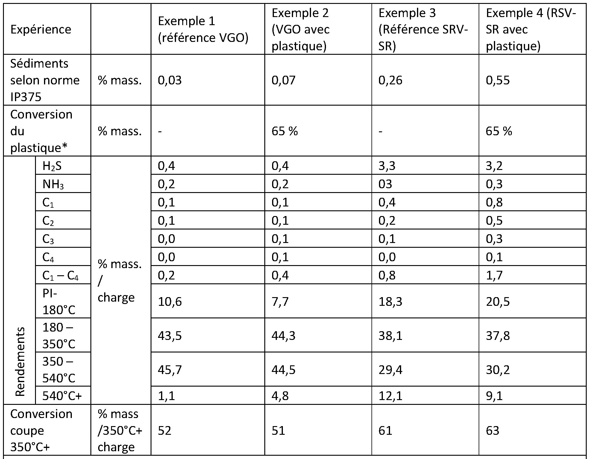
Claims
Priority Applications (2)
| Application Number | Priority Date | Filing Date | Title |
|---|---|---|---|
| EP24732232.4A EP4728028A1 (fr) | 2023-06-14 | 2024-06-07 | Hydroconversion en lit bouillonnant ou hybride d'une charge comportant une fraction plastique et une fraction hydrocarbonee lourde non?asphaltenique |
| CN202480039266.9A CN121358828A (zh) | 2023-06-14 | 2024-06-07 | 包含塑料馏分和非沥青质重质烃馏分的原料的沸腾床或杂化床加氢转化 |
Applications Claiming Priority (2)
| Application Number | Priority Date | Filing Date | Title |
|---|---|---|---|
| FR2306075A FR3149899A1 (fr) | 2023-06-14 | 2023-06-14 | Hydroconversion en lit bouillonnant ou hybride d’une charge comportant une fraction plastique et une fraction hydrocarbonee lourde non-asphaltenique |
| FRFR2306075 | 2023-06-14 |
Publications (1)
| Publication Number | Publication Date |
|---|---|
| WO2024256280A1 true WO2024256280A1 (fr) | 2024-12-19 |
Family
ID=88207441
Family Applications (1)
| Application Number | Title | Priority Date | Filing Date |
|---|---|---|---|
| PCT/EP2024/065707 Ceased WO2024256280A1 (fr) | 2023-06-14 | 2024-06-07 | Hydroconversion en lit bouillonnant ou hybride d'une charge comportant une fraction plastique et une fraction hydrocarbonee lourde non‐asphaltenique |
Country Status (4)
| Country | Link |
|---|---|
| EP (1) | EP4728028A1 (fr) |
| CN (1) | CN121358828A (fr) |
| FR (1) | FR3149899A1 (fr) |
| WO (1) | WO2024256280A1 (fr) |
Citations (10)
| Publication number | Priority date | Publication date | Assignee | Title |
|---|---|---|---|---|
| US4354852A (en) | 1981-04-24 | 1982-10-19 | Hydrocarbon Research, Inc. | Phase separation of hydrocarbon liquids using liquid vortex |
| US4457831A (en) | 1982-08-18 | 1984-07-03 | Hri, Inc. | Two-stage catalytic hydroconversion of hydrocarbon feedstocks using resid recycle |
| US4495060A (en) | 1982-12-27 | 1985-01-22 | Hri, Inc. | Quenching hydrocarbon effluent from catalytic reactor to avoid precipitation of asphaltene compounds |
| US4521295A (en) | 1982-12-27 | 1985-06-04 | Hri, Inc. | Sustained high hydroconversion of petroleum residua feedstocks |
| US20050241991A1 (en) | 2004-04-28 | 2005-11-03 | Headwaters Heavy Oil, Llc | Ebullated bed hydroprocessing methods and systems and methods of upgrading an existing ebullated bed system |
| FR2933710A1 (fr) * | 2008-07-10 | 2010-01-15 | Inst Francais Du Petrole | Procede de conversion comprenant un desasphaltage et une conversion de residu |
| US20110167713A1 (en) * | 2010-01-12 | 2011-07-14 | IFP Energies Nouvelles | Process for direct hydorliquefaction of biomass comprising two stages of ebullating bed hydroconversion |
| FR3033797A1 (fr) | 2015-03-16 | 2016-09-23 | Ifp Energies Now | Procede ameliore de conversion de charges hydrocarbonees lourdes |
| WO2020129020A1 (fr) | 2018-12-21 | 2020-06-25 | Eni S.P.A. | Procédé d'hydroconversion de mélange de polymères |
| US10822553B2 (en) | 2004-04-28 | 2020-11-03 | Hydrocarbon Technology & Innovation, Llc | Mixing systems for introducing a catalyst precursor into a heavy oil feedstock |
-
2023
- 2023-06-14 FR FR2306075A patent/FR3149899A1/fr active Pending
-
2024
- 2024-06-07 WO PCT/EP2024/065707 patent/WO2024256280A1/fr not_active Ceased
- 2024-06-07 EP EP24732232.4A patent/EP4728028A1/fr active Pending
- 2024-06-07 CN CN202480039266.9A patent/CN121358828A/zh active Pending
Patent Citations (13)
| Publication number | Priority date | Publication date | Assignee | Title |
|---|---|---|---|---|
| US4354852A (en) | 1981-04-24 | 1982-10-19 | Hydrocarbon Research, Inc. | Phase separation of hydrocarbon liquids using liquid vortex |
| US4457831A (en) | 1982-08-18 | 1984-07-03 | Hri, Inc. | Two-stage catalytic hydroconversion of hydrocarbon feedstocks using resid recycle |
| US4495060A (en) | 1982-12-27 | 1985-01-22 | Hri, Inc. | Quenching hydrocarbon effluent from catalytic reactor to avoid precipitation of asphaltene compounds |
| US4521295A (en) | 1982-12-27 | 1985-06-04 | Hri, Inc. | Sustained high hydroconversion of petroleum residua feedstocks |
| US10822553B2 (en) | 2004-04-28 | 2020-11-03 | Hydrocarbon Technology & Innovation, Llc | Mixing systems for introducing a catalyst precursor into a heavy oil feedstock |
| US20050241991A1 (en) | 2004-04-28 | 2005-11-03 | Headwaters Heavy Oil, Llc | Ebullated bed hydroprocessing methods and systems and methods of upgrading an existing ebullated bed system |
| US10941353B2 (en) | 2004-04-28 | 2021-03-09 | Hydrocarbon Technology & Innovation, Llc | Methods and mixing systems for introducing catalyst precursor into heavy oil feedstock |
| FR2933710A1 (fr) * | 2008-07-10 | 2010-01-15 | Inst Francais Du Petrole | Procede de conversion comprenant un desasphaltage et une conversion de residu |
| US20110167713A1 (en) * | 2010-01-12 | 2011-07-14 | IFP Energies Nouvelles | Process for direct hydorliquefaction of biomass comprising two stages of ebullating bed hydroconversion |
| US8623102B2 (en) | 2010-01-12 | 2014-01-07 | IFP Energies Nouvelles | Process for direct hydorliquefaction of biomass comprising two stages of ebullating bed hydroconversion |
| FR3033797A1 (fr) | 2015-03-16 | 2016-09-23 | Ifp Energies Now | Procede ameliore de conversion de charges hydrocarbonees lourdes |
| WO2020129020A1 (fr) | 2018-12-21 | 2020-06-25 | Eni S.P.A. | Procédé d'hydroconversion de mélange de polymères |
| US20220041937A1 (en) * | 2018-12-21 | 2022-02-10 | Eni S.P.A. | Process for polymer mixture hydroconversion |
Non-Patent Citations (3)
| Title |
|---|
| "Catalysis by Transition Metal Sulphides", TECHNIP, 2013 |
| AICHE: "Hydroprocessing and Hydroconversion of Residue Fractions", SECOND GENERATION EBULLATED BED TECHNOLOGY, no. 46d |
| D.R. LIDE: "CRC Handbook of Chemistry and Physics", 2000, CRC PRESS |
Also Published As
| Publication number | Publication date |
|---|---|
| CN121358828A (zh) | 2026-01-16 |
| EP4728028A1 (fr) | 2026-04-22 |
| FR3149899A1 (fr) | 2024-12-20 |
Similar Documents
| Publication | Publication Date | Title |
|---|---|---|
| FR3098522A1 (fr) | Procédé de conversion d’une charge contenant de l’huile de pyrolyse | |
| FR3021326A1 (fr) | Procede de conversion d'une charge hydrocarbonee lourde integrant un desasphaltage selectif en amont de l'etape de conversion. | |
| EP4486852A1 (fr) | Hydroconversion en lit bouillonnant ou hybride bouillonnant-entraîné d'une charge comportant une fraction d'huile végétale ou animale | |
| WO2023066694A1 (fr) | Procede de traitement d'huiles de pyrolyse de plastiques et/ou de combustibles solides de recuperation chargees en impuretes | |
| EP4334411A1 (fr) | Procede integre de traitement d'huiles de pyrolyse de plastiques et/ou de combustibles solides de recuperation chargees en impuretes | |
| EP4728028A1 (fr) | Hydroconversion en lit bouillonnant ou hybride d'une charge comportant une fraction plastique et une fraction hydrocarbonee lourde non?asphaltenique | |
| WO2012085408A1 (fr) | Procede de conversion de charge hydrocarbonee comprenant une huile de schiste par decontamination, hydroconversion en lit bouillonnant, et fractionnement par distillation atmospherique | |
| WO2023117596A1 (fr) | Hydroconversion en lit bouillonnant ou hybride bouillonnant entraîné d'une charge comportant une fraction plastique | |
| FR3149900A1 (fr) | Hydroconversion en lit bouillonnant ou hybride promue par de l’h2s d’une charge comportant une fraction plastique | |
| EP4608932A1 (fr) | Procede de traitement en lit fixe d'une charge lourde d'origine fossile comportant une fraction d'huile de pyrolyse de plastiques | |
| WO2023174767A1 (fr) | Hydroconversion en lit bouillonnant ou hybride bouillonnant‐entraîné d'une charge comportant une fraction d'huile de pyrolyse de plastiques et/ou de combustibles solides de recuperation | |
| EP4367207A1 (fr) | Hydroconversion en lit entraine d'une charge hydrocarbonee lourde comprenant le mélange de ladite charge avec un précurseur de catalyseur contenant un additif organique | |
| WO2023280625A1 (fr) | Hydroconversion en lit entraine d'une charge hydrocarbonee lourd comprenant le prémélange de ladite charge avec un additif organique | |
| EP4367206A1 (fr) | Hydroconversion en lit hybride bouillonnant-entraîné d'une charge hydrocarbonee lourde comprenant le mélange de ladite charge avec un précurseur de catalyseur contenant un additif organique | |
| EP4367204A1 (fr) | Hydroconversion en lit hybride bouillonnant-entraîné d'une charge hydrocarbonee lourde comprenant le prémélange de ladite charge avec un additif organique | |
| FR3141183A1 (fr) | Hydroconversion d’une charge plastique promue par du soufre et en presence d’un catalyseur bi-fonctionnel zeolithique | |
| FR3141184A1 (fr) | Hydroconversion d’une charge plastique promue par du soufre et en presence d’un catalyseur bi-fonctionnel silico-aluminique | |
| EP4419627A1 (fr) | Procede de traitement d'huiles de pyrolyse de plastiques et/ou de combustibles solides de recuperation chargees en impuretes | |
| WO2024245769A1 (fr) | Procede de production de distillats moyens et de naphta d'une charge comportant une fraction d'huile de pyrolyse paraffinique et olefiniques |
Legal Events
| Date | Code | Title | Description |
|---|---|---|---|
| 121 | Ep: the epo has been informed by wipo that ep was designated in this application |
Ref document number: 24732232 Country of ref document: EP Kind code of ref document: A1 |
|
| WWE | Wipo information: entry into national phase |
Ref document number: 2024732232 Country of ref document: EP |
|
| NENP | Non-entry into the national phase |
Ref country code: DE |
|
| ENP | Entry into the national phase |
Ref document number: 2024732232 Country of ref document: EP Effective date: 20260114 |
|
| ENP | Entry into the national phase |
Ref document number: 2024732232 Country of ref document: EP Effective date: 20260114 |
|
| ENP | Entry into the national phase |
Ref document number: 2024732232 Country of ref document: EP Effective date: 20260114 |
|
| ENP | Entry into the national phase |
Ref document number: 2024732232 Country of ref document: EP Effective date: 20260114 |
|
| WWP | Wipo information: published in national office |
Ref document number: 2024732232 Country of ref document: EP |