WO2024257215A1 - Mounting device and processing region setting method - Google Patents
Mounting device and processing region setting method Download PDFInfo
- Publication number
- WO2024257215A1 WO2024257215A1 PCT/JP2023/021899 JP2023021899W WO2024257215A1 WO 2024257215 A1 WO2024257215 A1 WO 2024257215A1 JP 2023021899 W JP2023021899 W JP 2023021899W WO 2024257215 A1 WO2024257215 A1 WO 2024257215A1
- Authority
- WO
- WIPO (PCT)
- Prior art keywords
- suction
- target
- pickup
- members
- head
- Prior art date
- Legal status (The legal status is an assumption and is not a legal conclusion. Google has not performed a legal analysis and makes no representation as to the accuracy of the status listed.)
- Ceased
Links
Images




Classifications
-
- H—ELECTRICITY
- H05—ELECTRIC TECHNIQUES NOT OTHERWISE PROVIDED FOR
- H05K—PRINTED CIRCUITS; CASINGS OR CONSTRUCTIONAL DETAILS OF ELECTRIC APPARATUS; MANUFACTURE OF ASSEMBLAGES OF ELECTRICAL COMPONENTS
- H05K13/00—Apparatus or processes specially adapted for manufacturing or adjusting assemblages of electric components
- H05K13/04—Mounting of components, e.g. of leadless components
-
- H—ELECTRICITY
- H05—ELECTRIC TECHNIQUES NOT OTHERWISE PROVIDED FOR
- H05K—PRINTED CIRCUITS; CASINGS OR CONSTRUCTIONAL DETAILS OF ELECTRIC APPARATUS; MANUFACTURE OF ASSEMBLAGES OF ELECTRICAL COMPONENTS
- H05K13/00—Apparatus or processes specially adapted for manufacturing or adjusting assemblages of electric components
- H05K13/08—Monitoring manufacture of assemblages
Definitions
- This specification discloses an implementation device and a method for setting a processing area.
- a mounting device capable of simultaneously picking up multiple components using multiple pickup members that processes images of simultaneously picked up components to recognize the pickup misalignment of the components, and then corrects the pickup misalignment before mounting each component.
- the mounting device in Patent Document 1 sets an area for each component that is the component size plus a constant that takes into account the component's inclination and pickup misalignment, and recognizes the pickup misalignment for each component by processing the image of the set area as the processing area.
- the primary objective of this disclosure is to prevent the processing area of image processing from becoming larger than necessary when performing simultaneous adsorption.
- the mounting device of the present disclosure is A mounting device that uses a suction member to pick up a component supplied to a supply position, processes an image captured after the component is picked up to recognize a component suction misalignment, and corrects the suction misalignment before mounting the component, an acquisition unit that acquires, for each pickup member, a positional deviation of each pickup member relative to a respective supply position of the target components to be simultaneously picked up when the plurality of pickup members simultaneously pick up the plurality of components; a setting unit that sets a processing area of the image processing for each of the target parts by offsetting a predetermined area in the image for each of the pickup members that simultaneously picks up the target parts based on the positional deviation for each of the pickup members acquired by the acquisition unit;
- the gist of the invention is to provide the following:
- the positional deviation of each pickup member relative to each supply position of the target components for simultaneous pickup is acquired for each pickup member.
- a processing area is set for each target component by offsetting a specific area defined in the image for each pickup member based on the positional deviation for each pickup member. This makes it possible to prevent the processing area for image processing from becoming unnecessarily large when performing simultaneous pickup.
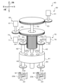
- FIG. 1 is a schematic configuration diagram of a mounting apparatus 10.
- FIG. 2 is a schematic diagram of a head 40.
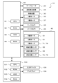
- FIG. 2 is a block diagram showing electrical connections of the mounting apparatus 10.
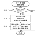
- 11 is a flowchart showing an example of a feeder position recognition process.
- 11 is a flowchart showing an example of a simultaneous adsorption process.
- FIG. 13 is an explanatory diagram showing an example of a center FC between target feeders and a center NC between target nozzles.
- FIG. 13 is an explanatory diagram showing an example of a center FC between target feeders and a center NC between target nozzles.
- FIG. 13 is an explanatory diagram showing an example of positional deviation during simultaneous chucking.
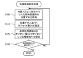
- 11 is a flowchart showing an example of a processing area setting process.
- FIG. 4 is an explanatory diagram showing an example of a reference processing area A0.
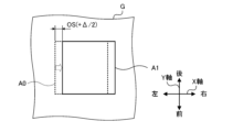
- FIG. 4 is an explanatory diagram showing an example of a processing region A1.
- FIG. 13 is an
- FIG. 1 is a schematic diagram of a mounting device 10.
- FIG. 2 is a schematic diagram of a head 40.
- FIG. 3 is a block diagram showing the electrical connections of the mounting device 10.
- the left-right direction (X-axis), front-back direction (Y-axis), and up-down direction (Z-axis) are as shown in FIG. 1.
- the mounting device 10 includes a tape feeder 20, a board transport device 24, a moving device 30, a head 40, a mark camera 25, a parts camera 26, and a control device 90 (see FIG. 3).
- a plurality of mounting devices 10 are arranged in the board transport direction (X-axis direction) to form a mounting line.
- the mounting line is managed by a management device 100 (see FIG. 3).
- the tape feeders 20 supply components to the mounting device 10, and are removably set in each slot formed in the feeder table on the front side of the mounting device 10, and are attached in a row in the X-axis direction (left and right direction).
- the tape feeder 20 includes a feeder section 21 and a reel 22 on which the tape 23 is wound.
- the tape 23 is pulled out from the reel 22 by a feed mechanism (not shown) of the feeder section 21 and sent to the component supply position.
- the tape 23 has cavities 23a (see FIG. 2) formed at predetermined intervals along its length. The cavities 23a accommodate components P.
- the components P accommodated in the cavities 23a are protected by a film covering the surface of the tape 23, and are exposed at the supply position by peeling off the film just before the supply position, and can be adsorbed by the suction nozzle 44 (adsorption member) of the head 40.
- the guide 23b that guides the tape 23 in the feed direction has a reference mark M (see FIG. 2) formed at a predetermined position on the upper surface.
- the substrate transport device 24 loads, fixes, and unloads the substrate S in the left-right direction (X-axis direction).
- the substrate transport device 24 has a pair of conveyor belts that are spaced apart from each other and span the left-right direction in FIG. 1. The substrate S is transported by these conveyor belts.
- the moving device 30 includes an X-axis slider 32 and a Y-axis slider 36, and moves the head 40 on the XY plane along the surface of the substrate S.
- the moving device 30 also includes an X-axis position sensor that detects the position of the X-axis slider 32 in the X-axis direction and a Y-axis position sensor that detects the position of the Y-axis slider 36 in the Y-axis direction, not shown.
- the X-axis slider 32 is supported by a pair of upper and lower X-axis guide rails 31 that are provided on the front surface of the Y-axis slider 36 so as to extend in the left-right direction.
- the X-axis slider 32 can be moved in the left-right direction (X-axis direction) by driving an X-axis motor 33 (see FIG. 3).
- the Y-axis slider 36 is supported by a pair of left and right Y-axis guide rails 35 that are provided on the upper stage of the housing 12 so as to extend in the front-rear direction.
- the Y-axis slider 36 can be moved in the front-rear direction (Y-axis direction) by driving a Y-axis motor 37 (see FIG. 3).
- a head 40 is attached to the X-axis slider 32. Therefore, the head 40 can be moved in the X and Y directions by the moving device 30.
- the head 40 picks up the component P supplied from the tape feeder 20 with the suction nozzle 44 and mounts it on the board S.
- the head 40 comprises a head body 41, a nozzle holder 42, a suction nozzle 44, an R-axis drive unit 50, a Q-axis drive unit 60, a first Z-axis drive unit 70, and a second Z-axis drive unit 75.
- the head 40 is configured as a rotary head in which multiple (e.g., 8, 20, 28, etc.) suction nozzles 44 are held by the head body 41.
- the head body 41 is a rotating body that can be rotated by the R-axis drive unit 50.
- the nozzle holders 42 are arranged at predetermined angular intervals in the circumferential direction relative to the head body 41, and are supported by the head body 41 so that they can be raised and lowered freely.
- a suction nozzle 44 is detachably attached to the tip of the nozzle holder 42.
- the suction nozzle 44 sucks up the component P by negative pressure supplied by a pressure supply device (not shown) through an internal flow path of the nozzle holder 42.
- the suction nozzle 44 also releases the suction of the component P by positive pressure supplied by the pressure supply device through an internal flow path of the nozzle holder 42.
- the pressure supply device is configured to include a negative pressure source, a positive pressure source, and a switching valve that can switch the pressure supplied to the suction port of each suction nozzle 44 between negative pressure, positive pressure, and atmospheric pressure, although not shown.
- the R-axis drive unit 50 rotates (revolves) the multiple nozzle holders 42 (multiple suction nozzles 44) in the circumferential direction around the central axis of the head body 41.
- the R-axis drive unit 50 includes an R-axis motor 51, an R-axis 52 extending in the axial direction from the central axis of the head body 41, a transmission gear 53 that transmits the rotation of the R-axis motor 51 to the R-axis 52, and an R-axis position sensor 55 that detects the rotation position of the R-axis motor 51.
- the R-axis drive unit 50 rotates the head body 41 by driving the R-axis 52 to rotate via the transmission gear 53 by the R-axis motor 51.
- Each nozzle holder 42 rotates (revolves) in the circumferential direction together with the suction nozzle 44 as the head body 41 rotates.
- the Q-axis drive unit 60 rotates (spins) each nozzle holder 42 (each suction nozzle 44) around its central axis.
- the Q-axis drive unit 60 includes a Q-axis motor 61, a cylindrical member 62, a transmission gear 63, a Q-axis gear 64, and a Q-axis position sensor 65 (see FIG. 3) that detects the rotational position of the Q-axis motor 61.
- the cylindrical member 62 is inserted coaxially and rotatably relative to the R-axis 52, and has a spur gear 62a formed on its outer circumferential surface.
- the transmission gear 63 transmits the rotation of the Q-axis motor 61 to the cylindrical member 62.
- the Q-axis gear 64 is provided on the upper portion of each nozzle holder 42, and engages with the spur gear 62a of the cylindrical member 62 so as to be slidable in the Z-axis direction (up and down direction).
- the Q-axis drive unit 60 rotates the cylindrical member 62 via the transmission gear 63 using the Q-axis motor 61, thereby collectively rotating each Q-axis gear 64 that meshes with the spur gear 62a of the cylindrical member 62.
- Each nozzle holder 42 rotates (spins) around its central axis together with the suction nozzle 44 due to the rotation of the Q-axis gear 64.
- the first and second Z-axis drive units 70, 75 are configured to be able to individually raise and lower the nozzle holder 42 in the Z-axis direction (lifting direction) at two lifting positions (predetermined positions) on the orbit of the nozzle holder 42.
- the first and second Z-axis drive units 70, 75 are arranged along the arrangement direction (X-axis direction) of the tape feeders 20.
- the first and second Z-axis drive devices 70, 75 include Z-axis sliders 72, 77, Z-axis motors 71, 76 that raise and lower the Z-axis sliders 72, 77, and Z-axis position sensors 74, 79 (see FIG. 3) that detect the raised and lowered positions of the Z-axis sliders 72, 77.
- the first and second Z-axis drive devices 70, 75 drive the Z-axis motors 71, 76, respectively, to raise and lower the Z-axis sliders 72, 77, thereby abutting against the nozzle holder 42 below the Z-axis sliders 72, 77, and raising and lowering the nozzle holder 42 together with the suction nozzle 44.
- the first and second Z-axis drive devices 70, 75 may use linear motors as the Z-axis motors 71, 76 to raise and lower the Z-axis sliders 72, 77, or may use a rotary motor and a ball screw mechanism to raise and lower the Z-axis sliders 72, 77.
- the head 40 is provided with two Z-axis drive devices 70, 75 that can raise and lower the nozzle holder 42 (suction nozzle 44) individually, and can perform the suction operation of the component P using the suction nozzle 44 individually.
- the head 40 can also use the two Z-axis drive devices 70, 75 to lower the two suction nozzles 44 approximately simultaneously to pick up two components P approximately simultaneously.
- the mark camera 25 is provided on the head 40 or the X-axis slider 32, and is configured to be movable in the X and Y directions by the moving device 30.
- the mark camera 25 captures images of the reference marks on the substrate S, the reference marks M on the tape feeder 20, the components P supplied to the supply position, etc. from above, and outputs the captured images to the control device 90.
- the parts camera 26 is disposed between the board transport device 24 and the tape feeder 20. When the suction nozzle 44 that has picked up the part P passes above the parts camera 26, the parts camera 26 captures an image of the part P from below, and outputs the captured image to the control device 90.
- the management device 100 is configured as a microprocessor centered on a CPU 101, and includes a ROM 102 that stores processing programs, an HDD 103 as an external storage device that stores various data, a RAM 104 used as a working area, an input/output interface, and the like.
- the external storage device is not limited to the HDD 103, and may be an SSD or the like.
- the management device 100 is connected to an input device 105 such as a keyboard and mouse through which an operator inputs various commands, and a display 106 that displays various information.
- the HDD 103 stores job information including a production program and other production information.
- the production program refers to a program that specifies which components P are to be mounted on which board S in which order in the mounting device 10, and how many boards S mounted in this manner are to be produced.
- the tape feeder 20 is removably set in each slot formed in the feeder table of the mounting device 10, and the reference position of the tape feeder 20 is determined by the pitch at which the slots are formed.
- the CPU 91 can recognize the mounting position of the tape feeder 20, including such variation, by performing a feeder position recognition process. In this embodiment, the CPU 91 recognizes the mounting position of the tape feeder 20 at least in the X-axis direction.
- the CPU 91 controls the moving device 30 so that the head 40 moves to a moving position where the center NC of the suction nozzle 44 (also called the target nozzle) that picks up the target parts to be picked up simultaneously coincides with the center FC between the target feeders (S210).
- the feeder pitch FP and the nozzle pitch NP are the same.
- the positions of the suction nozzles 44 in the head 40 are known in advance, for example, by calibration of the head 40 performed before the start of production.
- FIG. 6 shows a state in which the mounting positions Pa and Pb of the target feeders 20a and 20b are mounted at the reference position without error. Therefore, even without adjusting the position of the target nozzle (head 40), the center FC between the target feeders and the center NC between the target nozzles approximately coincide.
- FIG. 7 shows a state in which the mounting position Pb of the target feeder 20b is shifted to the right in the figure by a shift amount ⁇ from the reference position, resulting in a feeder pitch FP1 (>FP in FIG. 6). Therefore, if the target nozzle is left in the position of FIG. 6 (shown by a dotted line in FIG.
- the target nozzle (head 40) is moved to a moving position shifted to the right in FIG. 7 so that the center NC between the target nozzles coincides with the center FC between the target feeders.
- the effect of the misalignment amount ⁇ is evenly distributed to the left and right target nozzles 44a, 44b by the misalignment amount ( ⁇ /2), which reduces pickup and mounting failures compared to when the misalignment amount ⁇ is distributed to only one side.
- the head 40 is moved to a movement position where the misalignment of the target nozzle with respect to the mounting position of the target feeder is not biased toward either one of the target nozzles.
- the CPU 91 judges whether or not the suction of the target component to each target nozzle is complete (S240). If the CPU 91 judges that the suction of the target component is not complete, it rotates the head body 41 a predetermined amount to move the next target nozzle that has not yet picked up the target component above the supply position (S250), and executes the processes of S220 to S240. Therefore, each time simultaneous suction is performed by each target nozzle, a positional deviation is obtained in association with the target nozzle. On the other hand, if the CPU 91 judges that the suction of the target component is complete, it moves the head 40 above the part camera 26 and causes the part camera 26 to capture an image (target component) (S260). Next, the CPU 91 executes a processing area setting process for setting a processing area for image processing of each target component in the captured image (S270).
- FIG. 9 is a flow chart showing an example of the processing area setting process.
- the CPU 91 acquires the positional deviation during simultaneous pickup associated with the target nozzle that picks up the target component (S300).
- S300 the positional deviation acquired in S230 and stored in the HDD 103 (see FIG. 8) is acquired.
- the CPU 91 sets an offset amount OS based on the positional deviation during simultaneous pickup (S310), and offsets the reference processing area A0 associated with the target nozzle by the offset amount OS to set the processing area A1 of the target component (S320).
- the CPU 91 determines whether the setting of the processing area A1 has been completed for all target components in the image (S330), and if it determines that the setting has not been completed, it returns to S300, and if it determines that the setting has been completed, it ends the processing area setting process.
- the processing area A1 for the target part picked up by the target nozzle 44a is set by offsetting the reference processing area A0 to the left. In this way, the processing area A1 is set by offsetting the reference processing area A0 according to the positional deviation (amount and direction of deviation) during simultaneous pick-up.
- FIG. 12 is an explanatory diagram showing an example of a processing area A2 in the comparative example.
- the processing area A2 in the comparative example is set as an area obtained by enlarging the reference processing area A0 by adding the positional deviation ( ⁇ /2) at the time of simultaneous pickup to the left and right of the reference processing area A0 as a processing area for each target part picked up by the target nozzles 44a and 44b, for example.
- the processing area for each target part is larger than in this embodiment, and as a result, the processing time for image processing is longer.
- the head 40 is a rotary head capable of picking up multiple parts and the number of processing areas in the image G is relatively large, delays in processing time become a problem.
- the processing area A1 is set by offsetting the reference processing area A0 without enlarging it, so that the processing area A1 does not become larger than necessary, and it is possible to prevent the processing time for image processing from becoming longer.
- the CPU 91 performs image processing on the processing area A1 of each target component to recognize the suction deviation of each target component (S280).
- the CPU 91 performs image processing on the processing area A1 to recognize the target components, detect their center positions, and calculate the position deviation from the center position NO of each suction nozzle 44 in the image G to recognize the suction deviation of each target component.
- the CPU 91 corrects the mounting position of each target component based on the suction deviation and mounts the target components on the board S (S290), and ends the simultaneous suction process.
- the CPU 91 moves the head 40 so that the target components sucked by the suction nozzle 44 are positioned above the corrected mounting position, and lowers the suction nozzle 44 to mount the target components on the board S.
- the CPU 91 performs the mounting operation of S290 until the target components sucked by the multiple suction nozzles 44 are mounted.
- the control device 90 that executes S230 of the simultaneous pickup process of this embodiment corresponds to the acquisition unit of this disclosure, and the control device 90 that executes S270 of the simultaneous pickup process corresponds to the setting unit.
- the head 40 corresponds to the head
- the moving device 30 corresponds to the moving unit
- the control device 90 that executes S210 of the simultaneous pickup process corresponds to the movement control unit.
- the tape feeder 20 corresponds to the feeder
- the mark camera 25 corresponds to the imaging unit.
- an example of a processing area setting method of this disclosure is also clarified by explaining the operation of the mounting device 10.
- the positional deviation of the target nozzle relative to the mounting position of the target feeder (the supply position of the target components to be picked up simultaneously) is obtained for each target nozzle.
- a processing area A1 is set for each target component by offsetting a reference processing area A0 (predetermined area) defined in image G for each simultaneously picked up target nozzle based on the positional deviation for each target nozzle. This makes it possible to prevent the processing area A1 for image processing from becoming unnecessarily large when simultaneous pickup is performed, and therefore makes it possible to properly recognize the pickup deviation of the target components while preventing the image processing time from becoming long.
- the head 40 is moved to a movement position where the positional deviation of the target nozzles relative to the mounting position of the target feeder is not biased towards any one of the target nozzles. Then, the positional deviation of the target nozzles is obtained based on the positions of the target nozzles that perform simultaneous pickup in the head 40 that has been moved to the movement position and the mounting position of the target feeder. Therefore, when performing simultaneous pickup while preventing the positional deviation of each target nozzle relative to each supply position from being biased towards any one of the target nozzles, it is possible to prevent the processing area A1 from becoming unnecessarily large.
- the head 40 is moved to a position where the center FC between the two target feeders in the X-axis direction (predetermined direction) coincides with the center NC between the two target nozzles. This makes it possible to equalize the positional deviations of the target nozzles, stabilizing the suction of the target components while preventing the processing area A1 from becoming unnecessarily large.
- the mounting device 10 processes the image captured by the mark camera 25 to recognize the mounting position of the target feeder, and determines the movement position of the head 40 based on the recognized mounting position, and moves the head 40. Therefore, any error or positional deviation in the mounting position of the target feeder can be appropriately reflected in the setting of the processing area A1.
- each time multiple target nozzles are moved sequentially to the lifting position to perform simultaneous pickup a positional deviation corresponding to the target nozzle is obtained, and the reference processing area A0 is offset based on the positional deviation obtained corresponding to the target nozzle to set the processing area A1. Therefore, when simultaneous pickup is performed with the head 40 configured as a rotary head, the processing area A1 for each target component can be appropriately set.
- the present disclosure is applied to the setting of the processing area A1 in one image, but this is not limited to this.
- the present disclosure may be applied to the setting of the processing area in multiple images. Since super-resolution processing requires image processing of the processing areas of multiple images, offsetting and setting the processing area without enlarging it has a significant effect in shortening the processing time. For this reason, there is great significance in applying the present disclosure.
- the head 40 is a rotary head, but this is not limited to this and any configuration that allows simultaneous suction with multiple suction nozzles 44 may be used.
- a parallel-type head having multiple suction nozzles 44 arranged along the X-axis direction and each of which can be raised and lowered independently may be used.
- the head is not limited to one in which two suction nozzles 44 perform simultaneous suction, but may be one in which three or more suction nozzles 44 perform simultaneous suction.
- the CPU 91 recognizes the mounting position of the tape feeder 20 based on an image, but this is not limited thereto, and the mounting position of the tape feeder 20 may be recognized using a position detection sensor or the like. Also, while the CPU 91 recognizes the mounting position of the tape feeder 20 as the supply position of the target component, the supply position of the target component may be directly recognized by recognizing the component P from an image of the component P in the cavity 23a captured by the mark camera 25. Note that if the supply position of the target component is shifted in the Y direction, the processing area A1 may be set by offsetting the position shift in the Y direction in the same way as in the X direction.
- the head 40 is moved to a moving position where the center FC between the target feeders and the center NC between the target nozzles coincide, thereby equalizing the positional deviation during simultaneous suction for the two target nozzles, but this is not limited to the above.
- the positional deviation during simultaneous suction may be different for the two target nozzles.
- the positional deviation during simultaneous suction may remain biased toward one of the target nozzles, such as when a positional deviation occurs only in one of the target nozzles.
- simultaneous suction may be performed without adjusting the moving position of the target nozzle (head 40) while remaining biased toward one of the target nozzles. Even in such a case, by applying the present disclosure, it is possible to prevent the processing area A1 from becoming unnecessarily large when simultaneous suction is performed.
- the operation of the mounting device 10 has been described, but it may take the form of a processing area setting method for setting a processing area A1 for image processing, or an image processing method for setting a processing area A1 and performing image processing.
- the acquisition unit for acquiring the positional deviation of each suction nozzle 44 and the setting unit for setting the processing area may each be provided in separate devices.
- This disclosure can be used in technical fields such as mounting processing and image processing.
Landscapes
- Engineering & Computer Science (AREA)
- Manufacturing & Machinery (AREA)
- Microelectronics & Electronic Packaging (AREA)
- Operations Research (AREA)
- Supply And Installment Of Electrical Components (AREA)
Abstract
Description
本明細書は、実装装置および処理領域設定方法を開示する。 This specification discloses an implementation device and a method for setting a processing area.
従来、複数の部品を複数の吸着部材で同時吸着可能な実装装置において、同時吸着した部品を撮像した画像を画像処理して部品の吸着ずれを認識し、その吸着ずれを補正して各部品を実装するものが提案されている。例えば、特許文献1の実装装置では、部品サイズに、部品の傾きや吸着ずれ等を考慮した定数を加えた領域を部品毎に設定し、設定した領域を処理領域として画像処理することで、部品毎に吸着ずれを認識する。 In the past, a mounting device capable of simultaneously picking up multiple components using multiple pickup members has been proposed that processes images of simultaneously picked up components to recognize the pickup misalignment of the components, and then corrects the pickup misalignment before mounting each component. For example, the mounting device in Patent Document 1 sets an area for each component that is the component size plus a constant that takes into account the component's inclination and pickup misalignment, and recognizes the pickup misalignment for each component by processing the image of the set area as the processing area.
ここで、同時吸着を行う吸着部材の吸着位置自体に、部品が供給される供給位置とのずれが生じる場合がある。そのため、吸着位置自体のずれを考慮して、上述した特許文献1よりも大きな処理領域を設定することが考えられるが、画像処理に必要以上に時間がかかってしまう。 Here, there may be a misalignment between the pickup position of the simultaneous pickup members and the supply position to which the components are supplied. For this reason, it may be possible to set a processing area larger than that of the above-mentioned Patent Document 1, taking into account the misalignment of the pickup position itself, but this would result in image processing taking longer than necessary.
本開示は、同時吸着を行う際に、画像処理の処理領域が必要以上に大きくなるのを防止することを主目的とする。 The primary objective of this disclosure is to prevent the processing area of image processing from becoming larger than necessary when performing simultaneous adsorption.
本開示は、上述の主目的を達成するために以下の手段を採った。 This disclosure takes the following steps to achieve the above-mentioned primary objective:
本開示の実装装置は、
供給位置に供給された部品を吸着部材で吸着し、吸着後に撮像した画像を画像処理して部品の吸着ずれを認識し、該吸着ずれを補正して部品を実装する実装装置であって、
複数の前記吸着部材により複数の部品の同時吸着が行われる際に、該同時吸着の対象部品の各供給位置に対する各吸着部材の位置ずれを前記吸着部材毎に取得する取得部と、
前記対象部品を同時吸着した前記吸着部材毎に前記画像内に定められた所定領域を前記取得部が取得した前記吸着部材毎の位置ずれに基づいてオフセットすることで、前記対象部品毎に前記画像処理の処理領域を設定する設定部と、
を備えることを要旨とする。
The mounting device of the present disclosure is
A mounting device that uses a suction member to pick up a component supplied to a supply position, processes an image captured after the component is picked up to recognize a component suction misalignment, and corrects the suction misalignment before mounting the component,
an acquisition unit that acquires, for each pickup member, a positional deviation of each pickup member relative to a respective supply position of the target components to be simultaneously picked up when the plurality of pickup members simultaneously pick up the plurality of components;
a setting unit that sets a processing area of the image processing for each of the target parts by offsetting a predetermined area in the image for each of the pickup members that simultaneously picks up the target parts based on the positional deviation for each of the pickup members acquired by the acquisition unit;
The gist of the invention is to provide the following:
本開示の実装装置では、同時吸着の対象部品の各供給位置に対する各吸着部材の位置ずれを吸着部材毎に取得する。また、吸着部材毎に画像内に定められた所定領域を吸着部材毎の位置ずれに基づいてオフセットすることで、対象部品毎に処理領域を設定する。これにより、同時吸着を行う際に、画像処理の処理領域が必要以上に大きくなるのを防止することができる。 In the mounting device disclosed herein, the positional deviation of each pickup member relative to each supply position of the target components for simultaneous pickup is acquired for each pickup member. In addition, a processing area is set for each target component by offsetting a specific area defined in the image for each pickup member based on the positional deviation for each pickup member. This makes it possible to prevent the processing area for image processing from becoming unnecessarily large when performing simultaneous pickup.
本開示の実施形態について図面を用いて説明する。図1は、実装装置10の概略構成図である。図2は、ヘッド40の概略構成図である。図3は、実装装置10の電気的な接続関係を示すブロック図である。なお、本実施形態において、左右方向(X軸)、前後方向(Y軸)及び上下方向(Z軸)は、図1に示す通りとする。
An embodiment of the present disclosure will be described with reference to the drawings. FIG. 1 is a schematic diagram of a
実装装置10は、図1に示すように、テープフィーダ20と、基板搬送装置24と、移動装置30と、ヘッド40と、マークカメラ25と、パーツカメラ26と、制御装置90(図3参照)とを備える。実装装置10は、基板搬送方向(X軸方向)に複数配置されて実装ラインを構成する。実装ラインは、管理装置100(図3参照)により管理される。
As shown in FIG. 1, the
テープフィーダ20は、実装装置10に部品を供給するものであり、実装装置10の前側のフィーダ台に形成された各スロットに着脱可能にセットされ、X軸方向(左右方向)に複数並んで取り付けられている。テープフィーダ20は、フィーダ部21と、テープ23が巻回されたリール22とを備え、フィーダ部21の図示しない送り機構によりリール22からテープ23を引き出して部品の供給位置へ送り出す。テープ23には、その長手方向に沿って所定間隔毎にキャビティ23a(図2参照)が形成されている。キャビティ23aには、部品Pが収容されている。なお、キャビティ23aに収容された部品Pは、テープ23の表面を覆うフィルムによって保護されており、供給位置の手前でフィルムが剥がされることで供給位置にて露出した状態となり、ヘッド40の吸着ノズル44(吸着部材)により吸着可能となる。なお、テープ23を送り方向にガイドするガイド23bには、上面の所定位置に基準マークM(図2参照)が形成されている。
The
基板搬送装置24は、左右方向(X軸方向)に基板Sの搬入、固定および搬出を行うものである。基板搬送装置24は、図1の前後に間隔を空けて設けられ左右方向に架け渡された1対のコンベアベルトを有する。基板Sは、このコンベアベルトにより搬送される。
The
移動装置30は、X軸スライダ32とY軸スライダ36とを備え、基板Sの表面に沿うXY平面上でヘッド40を移動させる。また、移動装置30は、図示しないが、X軸スライダ32のX軸方向における位置を検知するX軸位置センサやY軸スライダ36のY軸方向における位置を検知するY軸位置センサなども備える。X軸スライダ32は、Y軸スライダ36の前面に左右方向に延在するように設けられた上下一対のX軸ガイドレール31に支持される。X軸スライダ32は、X軸モータ33(図3参照)の駆動によって左右方向(X軸方向)に移動可能である。Y軸スライダ36は、筐体12の上段部に前後方向に延在するように設けられた左右一対のY軸ガイドレール35に支持される。Y軸スライダ36は、Y軸モータ37(図3参照)の駆動によって前後方向(Y軸方向)に移動可能である。X軸スライダ32にはヘッド40が取り付けられている。したがって、ヘッド40は、移動装置30によりXY方向に移動可能となっている。
The
ヘッド40は、テープフィーダ20から供給された部品Pを吸着ノズル44で吸着し、基板Sに実装する。ヘッド40は、図2に示すように、ヘッド本体41と、ノズルホルダ42と、吸着ノズル44と、R軸駆動装置50と、Q軸駆動装置60と、第1Z軸駆動装置70と、第2Z軸駆動装置75とを備える。ヘッド40は、複数(例えば8個や20個、28個など)の吸着ノズル44がヘッド本体41に保持されるロータリヘッドとして構成されている。
The
ヘッド本体41は、R軸駆動装置50によって回転可能な回転体である。ノズルホルダ42は、ヘッド本体41に対して円周方向に所定角度間隔で配列され、且つ、ヘッド本体41に昇降自在に支持されている。ノズルホルダ42の先端部には、吸着ノズル44が着脱可能に取り付けられる。吸着ノズル44は、ノズルホルダ42の内部流路を介して圧力供給装置(図示せず)により供給される負圧により部品Pを吸着する。また、吸着ノズル44は、ノズルホルダ42の内部流路を介して圧力供給装置により供給される正圧により部品Pの吸着を解除する。圧力供給装置は、図示しないが、負圧源と、正圧源と、各吸着ノズル44の吸着口に供給する圧力を負圧と正圧と大気圧とに切り替え可能な切替弁と、を備えて構成される。
The
R軸駆動装置50は、複数のノズルホルダ42(複数の吸着ノズル44)をヘッド本体41の中心軸回りに円周方向に沿って旋回(公転)させる。R軸駆動装置50は、図2に示すように、R軸モータ51と、ヘッド本体41の中心軸から軸方向に延出されたR軸52と、R軸モータ51の回転をR軸52に伝達する伝達ギヤ53と、R軸モータ51の回転位置を検知するR軸位置センサ55とを備える。R軸駆動装置50は、R軸モータ51により伝達ギヤ53を介してR軸52を回転駆動することにより、ヘッド本体41を回転させる。各ノズルホルダ42は、ヘッド本体41の回転によって、吸着ノズル44と一体となって円周方向に旋回(公転)する。
The R-
Q軸駆動装置60は、各ノズルホルダ42(各吸着ノズル44)をその中心軸回りに回転(自転)させる。Q軸駆動装置60は、図2に示すように、Q軸モータ61と、円筒部材62と、伝達ギヤ63と、Q軸ギヤ64と、Q軸モータ61の回転位置を検知するQ軸位置センサ65(図3参照)とを備える。円筒部材62は、R軸52に対して同軸かつ相対回転可能に挿通され、外周面に平歯ギヤ62aが形成されている。伝達ギヤ63は、Q軸モータ61の回転を円筒部材62に伝達するものである。Q軸ギヤ64は、各ノズルホルダ42の上部に設けられ、円筒部材62の平歯ギヤ62aとZ軸方向(上下方向)にスライド可能に噛み合う。Q軸駆動装置60は、Q軸モータ61により伝達ギヤ63を介して円筒部材62を回転駆動することにより、円筒部材62の平歯ギヤ62aと噛み合う各Q軸ギヤ64を纏めて回転させる。各ノズルホルダ42は、Q軸ギヤ64の回転によって、吸着ノズル44と一体となってその中心軸回りに回転(自転)する。
The Q-
第1および第2Z軸駆動装置70,75は、ノズルホルダ42の旋回(公転)軌道上の2つの昇降位置(所定位置)において、ノズルホルダ42をZ軸方向(昇降方向)に個別に昇降可能に構成されている。本実施形態では、第1および第2Z軸駆動装置70,75は、テープフィーダ20の並び方向(X軸方向)に沿って設けられている。
The first and second Z-
第1および第2Z軸駆動装置70,75は、図2に示すように、Z軸スライダ72,77と、Z軸スライダ72,77を昇降させるZ軸モータ71,76と、Z軸スライダ72,77の昇降位置を検知するZ軸位置センサ74,79(図3参照)とを備える。第1および第2Z軸駆動装置70,75は、それぞれZ軸モータ71,76を駆動してZ軸スライダ72,77を昇降させることにより、Z軸スライダ72,77の下方にあるノズルホルダ42と当接して、当該ノズルホルダ42を吸着ノズル44と一体的に昇降させる。なお、第1および第2Z軸駆動装置70,75は、Z軸モータ71,76としてリニアモータを用いてZ軸スライダ72,77を昇降させてもよいし、回転モータとボールねじ機構とを用いてZ軸スライダ72,77を昇降させてもよい。このように、ヘッド40は、それぞれノズルホルダ42(吸着ノズル44)を個別に昇降可能な2つのZ軸駆動装置70,75を備え、吸着ノズル44による部品Pの吸着動作を個別に行うことができる。また、ヘッド40は、2つのZ軸駆動装置70,75によって、2つの吸着ノズル44を略同時に下降させて2つの部品Pを略同時に吸着させることもできる。
2, the first and second Z-
マークカメラ25は、ヘッド40またはX軸スライダ32に設けられており、移動装置30によりXY方向に移動可能に構成されている。マークカメラ25は、基板Sに付された基準マークや、テープフィーダ20に付された基準マークM、供給位置に供給された部品Pなどを上方から撮像し、撮像した画像を制御装置90へ出力する。
The
パーツカメラ26は、基板搬送装置24とテープフィーダ20との間に配置されている。パーツカメラ26は、部品Pを吸着した吸着ノズル44がパーツカメラ26の上方を通過する際、その部品Pを下方から撮像し、撮像した画像を制御装置90へ出力する。
The
制御装置90は、図3に示すように、CPU91を中心とするマイクロプロセッサとして構成され、処理プログラムを記憶するROM92や各種データを記憶する外部記憶装置としてのHDD93、作業領域として用いられるRAM94、入出力インタフェースなどを備える。なお、外部記憶装置は、HDD93に限られず、SSDなどでもよい。制御装置90は、テープフィーダ20や基板搬送装置24、移動装置30(X軸モータ33、Y軸モータ37)、ヘッド40(R軸モータ51、Q軸モータ61、Z軸モータ71,76)、マークカメラ25、パーツカメラ26へ制御信号を出力する。また、制御装置90は、ヘッド40(R軸位置センサ55、Q軸位置センサ65、Z軸位置センサ74,79)やテープフィーダ20、移動装置30、マークカメラ25、パーツカメラ26からの信号を入力する。
As shown in FIG. 3, the
管理装置100は、図3に示すように、CPU101を中心とするマイクロプロセッサとして構成され、処理プログラムを記憶するROM102や各種データを記憶する外部記憶装置としてのHDD103、作業領域として用いられるRAM104、入出力インタフェースなどを備える。なお、外部記憶装置は、HDD103に限られず、SSDなどでもよい。管理装置100には、作業者が各種指令を入力するキーボード及びマウス等の入力デバイス105と、各種情報を表示するディスプレイ106とが接続されている。HDD103には、生産プログラムやその他の生産情報を含むジョブ情報が記憶されている。ここで、生産プログラムは、実装装置10において、どの基板Sにどの部品Pをどの順番で実装するか、また、そのように実装した基板Sを何枚生産するかを定めたものをいう。
As shown in FIG. 3, the
こうして構成された実装装置10では、テープフィーダ20の取付位置を認識するための処理を実行する。図4は、フィーダ位置認識処理の一例を示すフローチャートである。CPU91は、実装装置10にテープフィーダ20が取り付けられたか否かを判定し(S100)、取り付けられていないと判定すると、フィーダ位置認識処理を終了する。一方、CPU91は、テープフィーダ20が取り付けられたと判定すると、そのテープフィーダ20の上方にマークカメラ25を移動させて基準マークMを撮像させる(S110)。続いて、CPU91は、撮像した画像を画像処理して基準マークMを検出し、その基準マークMに基づいてテープフィーダ20の取付位置を認識してHDD103に記憶し(S120)、フィーダ位置認識処理を終了する。
The mounting
ここで、テープフィーダ20は、実装装置10のフィーダ台に形成された各スロットに着脱可能にセットされるものであり、スロットの形成ピッチによりテープフィーダ20の基準位置が定まる。しかし、テープフィーダ20やスロットの寸法誤差や摩耗などにより、基準位置に対して実際の取付位置に若干のばらつき(誤差)が生じることがある。CPU91は、フィーダ位置認識処理を行うことにより、そのようなばらつきを含むテープフィーダ20の取付位置を認識することができる。なお、本実施形態では、CPU91は、少なくともX軸方向におけるテープフィーダ20の取付位置を認識する。
Here, the
次に、部品Pの同時吸着処理を説明する。図5は、同時吸着処理の一例を示すフローチャートである。同時吸着処理では、CPU91は、同時吸着の対象部品を供給するテープフィーダ20(対象フィーダともいう)の取付位置に基づいて、対象フィーダ間の中心FCを検出する(S200)。本実施形態では、2つの吸着ノズル44で同時吸着を行うため、対象フィーダは2つである。各対象フィーダの取付位置は、フィーダ位置認識処理で認識されてHDD103に記憶された位置が用いられる。次に、CPU91は、同時吸着の対象部品を吸着する吸着ノズル44(対象ノズルともいう)の中心NCが対象フィーダ間の中心FCと一致する移動位置にヘッド40が移動するように移動装置30を制御する(S210)。
Next, the simultaneous pickup process of the parts P will be described. FIG. 5 is a flow chart showing an example of the simultaneous pickup process. In the simultaneous pickup process, the
ここで、図6,図7は、対象フィーダ間の中心FCと対象ノズル間の中心NCの一例を示す説明図である。図6,図7では、左右方向(X軸方向)に並んだ2つの対象フィーダを対象フィーダ20a,20bとし、2つの対象ノズルを対象ノズル44a,44bとする。対象フィーダ間の中心FCは、対象フィーダ20aの取付位置Paと対象フィーダ20bの取付位置Pbとに基づく左右方向のフィーダピッチFPの中心位置である。また、対象ノズル間の中心NCは、ヘッド40における対象ノズル44aの位置と対象ノズル44bの位置とに基づく左右方向のノズルピッチNPの中心位置である。なお、対象フィーダ20a,20bの取付位置Pa,Pbが基準位置の場合、フィーダピッチFPとノズルピッチNPとが一致する。また、ヘッド40における各吸着ノズル44の位置は、例えば生産開始前に実行されるヘッド40のキャリブレーション(較正)により、予め把握されている。
6 and 7 are explanatory diagrams showing an example of the center FC between the target feeders and the center NC between the target nozzles. In FIG. 6 and FIG. 7, the two target feeders arranged in the left-right direction (X-axis direction) are the
図6は、対象フィーダ20a,20bの取付位置Pa,Pbが基準位置に誤差なく取り付けられている状態を示す。このため、対象ノズル(ヘッド40)の位置を調整しなくても、対象フィーダ間の中心FCと対象ノズル間の中心NCとが略一致する。一方、図7は、対象フィーダ20bの取付位置Pbが基準位置に対してずれ量Δで図中右側にずれており、フィーダピッチFP1(>図6のFP)となっている状態を示す。このため、対象ノズルを図6の位置としたまま(図7に点線で図示)で対象部品を同時吸着すると、対象ノズル44bが吸着する対象部品にずれ量Δの影響が及び、吸着不良や実装不良が生じるおそれがある。そこで、本実施形態では、対象ノズル間の中心NCが対象フィーダ間の中心FCと一致するように、図7の右側にずらした移動位置を定めて、対象ノズル(ヘッド40)を移動させる。これにより、左右の対象ノズル44a,44bに、ずれ量Δの影響が均等にずれ量(Δ/2)ずつ及ぶため、ずれ量Δの影響が一方のみに及ぶ場合よりも吸着不良や実装不良を低減させることができる。このように、S210では、対象フィーダの取付位置に対する対象ノズルの位置ずれが、いずれか一方の対象ノズルに偏らない移動位置にヘッド40を移動させる。
FIG. 6 shows a state in which the mounting positions Pa and Pb of the
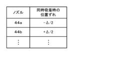
次に、CPU91は、Z軸駆動装置70,75により2つの対象ノズルを同時に下降させて、2つの対象ノズルに対象部品を同時吸着させる(S220)。また、CPU91は、同時吸着した対象ノズル毎に対象フィーダに対する位置ずれをそれぞれ取得してHDD103に記憶する(S230)。図8は、同時吸着時の位置ずれの一例を示す説明図であり、図7の位置ずれが記憶されている。なお、図7の各対象ノズルに対し右側のずれを正、左側のずれを負とする。このため、対象ノズル44aに位置ずれ(-Δ/2)が対応付けて記憶され、対象ノズル44bに位置ずれ(+Δ/2)が対応付けて記憶される。
Next, the
続いて、CPU91は、各対象ノズルへの対象部品の吸着が完了したか否かを判定する(S240)。CPU91は、対象部品の吸着が完了していないと判定すると、ヘッド本体41を所定量回転させて、対象部品を吸着していない次の対象ノズルを供給位置の上方へ移動させて(S250)、S220~S240の処理を実行する。このため、各対象ノズルで同時吸着が行われる度に、対象ノズルに対応付けて位置ずれが取得されることになる。一方、CPU91は、対象部品の吸着が完了したと判定すると、ヘッド40をパーツカメラ26の上方に移動させてパーツカメラ26により画像(対象部品)を撮像させる(S260)。続いて、CPU91は、撮像した画像において、各対象部品の画像処理の処理領域を設定するための処理領域設定処理を実行する(S270)。
Then, the
図9は、処理領域設定処理の一例を示すフローチャートである。処理領域設定処理では、CPU91は、対象部品を吸着している対象ノズルに対応付けられた同時吸着時の位置ずれを取得する(S300)。S300では、S230で取得されてHDD103に記憶された位置ずれ(図8参照)が取得される。次に、CPU91は、同時吸着時の位置ずれに基づくオフセット量OSを設定し(S310)、対象ノズルに対応付けられた基準処理領域A0をオフセット量OSでオフセットして対象部品の処理領域A1を設定する(S320)。そして、CPU91は、画像内の全ての対象部品について処理領域A1の設定が完了したか否かを判定し(S330)、設定が完了していないと判定するとS300に戻り、設定が完了したと判定すると処理領域設定処理を終了する。
FIG. 9 is a flow chart showing an example of the processing area setting process. In the processing area setting process, the
図10は、基準処理領域A0の一例を示す説明図である。図11は、処理領域A1の一例を示す説明図である。図10,図11では、パーツカメラ26により撮像された画像Gの一部を示す。図10に示すように、基準処理領域A0は、画像G内での吸着ノズル44の中心位置N0を中心として、部品Pのサイズと、キャビティ23a内での部品Pの位置ばらつきに伴うずれ量mとを考慮したサイズに定められている。画像G内での吸着ノズル44の中心位置N0は、上述したヘッド40のキャリブレーションにより把握された各吸着ノズル44の位置に基づいて定められる。なお、基準処理領域A0のサイズは、部品Pのサイズに拘わらず、キャビティ23aのサイズに基づいて定められてもよい。
FIG. 10 is an explanatory diagram showing an example of the reference processing area A0. FIG. 11 is an explanatory diagram showing an example of the processing area A1. FIGS. 10 and 11 show a portion of the image G captured by the
図11は、処理領域A1の一例として、図7の対象ノズル44bが吸着した対象部品用の処理領域A1を示す。図示するように、基準処理領域A0(図11に点線で図示)を、同時吸着時の位置ずれ(+Δ/2)に基づくオフセット量OSで、右側にオフセットした処理領域A1(図11に実線で図示)が設定される。即ち対象ノズル44bに対して対象部品の供給位置が右側にずれているため(図7参照)、対象ノズル44bが吸着した対象部品用の処理領域A1は基準処理領域A0を右側にオフセットして設定される。また、図示は省略するが、対象ノズル44aに対して対象部品の供給位置が左側にずれているため(図7参照)、対象ノズル44aが吸着した対象部品用の処理領域A1は基準処理領域A0を左側にオフセットして設定される。このように、基準処理領域A0を、同時吸着時の位置ずれ(ずれ量およびずれ方向)に応じてオフセットして処理領域A1が設定される。
11 shows, as an example of the processing area A1, the processing area A1 for the target part picked up by the
また、図12は、比較例の処理領域A2の一例を示す説明図である。比較例の処理領域A2は、例えば対象ノズル44a,44bが吸着した各対象部品用の処理領域として、同時吸着時の位置ずれ(Δ/2)を基準処理領域A0の左右にそれぞれ加えることで、基準処理領域A0を拡大した領域として設定される。このため、比較例では、本実施形態に比して対象部品毎の処理領域が大きくなり、結果的に画像処理の処理時間が長くなる。特に、ヘッド40が複数の部品を吸着可能なロータリヘッドであり、画像G内の処理領域の数が比較的多くなるため、処理時間の遅延が問題となる。本実施形態では、基準処理領域A0を拡大することなくオフセットして処理領域A1を設定するから、処理領域A1が必要以上に大きくならず、画像処理の処理時間が長くなるのを防止することができる。
FIG. 12 is an explanatory diagram showing an example of a processing area A2 in the comparative example. The processing area A2 in the comparative example is set as an area obtained by enlarging the reference processing area A0 by adding the positional deviation (Δ/2) at the time of simultaneous pickup to the left and right of the reference processing area A0 as a processing area for each target part picked up by the
こうしてS270(図9)の処理領域設定処理を実行すると、CPU91は、各対象部品の処理領域A1をそれぞれ画像処理して各対象部品の吸着ずれを認識する(S280)。S280では、CPU91は、処理領域A1を画像処理して対象部品を認識してその中心位置を検出し、画像G内における各吸着ノズル44の中心位置N0からの位置ずれを算出することで、対象部品の吸着ずれをそれぞれ認識する。続いて、CPU91は、吸着ずれに基づいて各対象部品の実装位置を補正して対象部品を基板Sに実装して(S290)、同時吸着処理を終了する。S290では、CPU91は、吸着ノズル44に吸着している対象部品が、補正した実装位置の上方に位置するようにヘッド40を移動させ、吸着ノズル44を下降させて対象部品を基板Sに実装させる。CPU91は、複数の吸着ノズル44に吸着している対象部品が実装されるまで、S290の実装動作を行う。
When the processing area setting process of S270 (FIG. 9) is thus executed, the
ここで、本実施形態の構成要素と本開示の構成要素との対応関係を明らかにする。本実施形態の同時吸着処理のS230を実行する制御装置90が本開示の取得部に相当し、同時吸着処理のS270を実行する制御装置90が設定部に相当する。ヘッド40がヘッドに相当し、移動装置30が移動部に相当し、同時吸着処理のS210を実行する制御装置90が移動制御部に相当する。テープフィーダ20がフィーダに相当し、マークカメラ25が撮像部に相当する。本実施形態では、実装装置10の動作を説明することにより本開示の処理領域設定方法の一例も明らかにしている。
Here, the correspondence between the components of this embodiment and the components of this disclosure will be clarified. The
以上説明した実施形態の実装装置10では、同時吸着が行われる際に、対象フィーダの取付位置(同時吸着の対象部品の供給位置)に対する対象ノズルの位置ずれを対象ノズル毎に取得する。また、同時吸着した対象ノズル毎に画像G内に定められた基準処理領域A0(所定領域)を、対象ノズル毎の位置ずれに基づいてオフセットすることで、対象部品毎に処理領域A1を設定する。これにより、同時吸着を行う際に、画像処理の処理領域A1が必要以上に大きくなるのを防止することができるから、画像処理の処理時間が長くなるのを防止しつつ対象部品の吸着ずれを適切に認識することができる。
In the mounting
また、実装装置10では、対象フィーダの取付位置に対する対象ノズルの位置ずれがいずれかの対象ノズルに偏らない移動位置にヘッド40を移動させる。そして、移動位置に移動したヘッド40において同時吸着を行う対象ノズルの位置と、対象フィーダの取付位置とに基づいて、対象ノズルの位置ずれを取得する。このため、各供給位置に対する各対象ノズルの位置ずれがいずれかの対象ノズルに偏らないようにして同時吸着を行う際に、処理領域A1が必要以上に大きくなるのを防止することができる。
In addition, in the mounting
また、実装装置10では、X軸方向(所定方向)における2つの対象フィーダ間の中心FCと2つの対象ノズル間の中心NCとが一致する位置を、移動位置としてヘッド40を移動させる。このため、各対象ノズルの位置ずれを均等化させて対象部品の吸着を安定化しつつ処理領域A1が必要以上に大きくなるのを防止することができる。
In addition, in the mounting
また、実装装置10では、マークカメラ25により撮像された画像を画像処理して対象フィーダの取付位置を認識し、認識した取付位置に基づいてヘッド40の移動位置を定めてヘッド40を移動させる。このため、対象フィーダの取付位置の誤差や位置ずれを処理領域A1の設定に適切に反映させることができる。
In addition, the mounting
また、実装装置10では、複数の対象ノズルが昇降位置に順次移動して同時吸着が行われる度に、対象ノズルに対応付けて位置ずれを取得し、対象ノズルに対応付けて取得された位置ずれに基づいて基準処理領域A0をオフセットして処理領域A1を設定する。このため、ロータリヘッドとして構成されたヘッド40で同時吸着を行う場合に、各対象部品の処理領域A1を適切に設定することができる。
In addition, in the mounting
なお、本開示は上述した実施形態に何ら限定されることはなく、本開示の技術的範囲に属する限り種々の態様で実施し得ることはいうまでもない。 It goes without saying that this disclosure is in no way limited to the above-described embodiments, and can be implemented in various forms as long as they fall within the technical scope of this disclosure.
例えば、上述した実施形態では、1つの画像内の処理領域A1の設定に本開示を適用したが、これに限られない。例えば、パーツカメラ26により撮像された複数の画像を用いて、より画質の高い画像を生成する超解像処理が実行される場合に、複数の画像内の処理領域の設定に本開示を適用してもよい。超解像処理では、複数の画像の処理領域を画像処理する必要があるから、処理領域を拡大することなくオフセットして設定することで処理時間を短縮する効果が大きくなる。このため、本開示を適用する意義が高いものとなる。
For example, in the above-described embodiment, the present disclosure is applied to the setting of the processing area A1 in one image, but this is not limited to this. For example, when super-resolution processing is performed to generate an image of higher image quality using multiple images captured by the
上述した実施形態では、ヘッド40をロータリヘッドとしたが、これに限られず、複数の吸着ノズル44で同時吸着が可能な構成であればよい。例えば、X軸方向に沿って配列され且つそれぞれ独立して昇降可能な複数の吸着ノズル44を有する並列型のヘッドでもよい。また、2つの吸着ノズル44が同時吸着を行うものに限られず、3つ以上の吸着ノズル44が同時吸着を行うものでもよい。
In the above embodiment, the
上述した実施形態では、CPU91が画像に基づいてテープフィーダ20の取付位置を認識したが、これに限られず、位置検出用のセンサなどを用いてテープフィーダ20の取付位置を認識してもよい。また、CPU91は、対象部品の供給位置としてテープフィーダ20の取付位置を認識したが、キャビティ23a内の部品Pをマークカメラ25で撮像した画像から部品Pを認識することで対象部品の供給位置を直接認識してもよい。なお、対象部品の供給位置がY方向にずれている場合、X方向と同様にY方向の位置ずれをオフセットして処理領域A1を設定してもよい。
In the above-described embodiment, the
上述した実施形態では、対象フィーダ間の中心FCと対象ノズル間の中心NCとが一致する移動位置にヘッド40を移動させることで、同時吸着時の位置ずれを2つの対象ノズルに均等化させたが、これに限られない。即ち、同時吸着時の位置ずれが一方の対象ノズルに偏らなければよく、同時吸着時の位置ずれが2つの対象ノズルで異なってもよい。あるいは、一方の対象ノズルのみに位置ずれが発生しているなど、同時吸着時の位置ずれが一方の対象ノズルに偏ったままでもよい。例えば、位置ずれが所定量以下であれば、一方の対象ノズルに偏ったまま対象ノズル(ヘッド40)の移動位置を調整せずに同時吸着を行ってもよい。そのような場合でも、本開示を適用することにより、同時吸着を行う際に処理領域A1が必要以上に大きくなるのを防止することができる。
In the above embodiment, the
上述した実施形態では、実装装置10の動作を説明したが、画像処理の処理領域A1を設定する処理領域設定方法の形態としてもよいし、処理領域A1を設定して画像処理を行う画像処理方法の形態としてもよい。また、各吸着ノズル44の位置ずれを取得する取得部と、処理領域の設定を行う設定部とが、それぞれ別々の装置に設けられていてもよい。
In the above embodiment, the operation of the mounting
本明細書では、出願当初の請求項5の「請求項1または2に記載の実装装置」を「請求項1ないし4のいずれか1項に記載の実装装置」に変更した技術思想も開示されている。
This specification also discloses the technical idea of changing the "mounting device according to
本開示は、実装処理の技術分野や画像処理の技術分野などに利用可能である。 This disclosure can be used in technical fields such as mounting processing and image processing.
10 実装装置、12 筐体、20 テープフィーダ、21 フィーダ部、22 リール、23 テープ、23a キャビティ、23b ガイド、24 基板搬送装置、25 マークカメラ、26 パーツカメラ、30 移動装置、31 X軸ガイドレール、32 X軸スライダ、33 X軸モータ、35 Y軸ガイドレール、36 Y軸スライダ、37 Y軸モータ、40 ヘッド、41 ヘッド本体、42 ノズルホルダ、44 吸着ノズル、50 R軸駆動装置、51 R軸モータ、52 R軸、53 伝達ギヤ、55 R軸位置センサ、60 Q軸駆動装置、61 Q軸モータ、62 円筒ギヤ、62a 平歯ギヤ、63 伝達ギヤ、64 Q軸ギヤ、65 Q軸位置センサ、70 第1Z軸駆動装置、71,76 Z軸モータ、72,77 Z軸スライダ、74,79 Z軸位置センサ、75 第2Z軸駆動装置、90 制御装置、91,101 CPU、92,102 ROM、93,103 HDD、94,104 RAM、100 管理装置、105 入力デバイス、106 ディスプレイ、A0 基準処理領域、A1,A2 処理領域、M 基準マーク、P 部品、S 基板。 10 mounting device, 12 housing, 20 tape feeder, 21 feeder section, 22 reel, 23 tape, 23a cavity, 23b guide, 24 substrate transport device, 25 mark camera, 26 parts camera, 30 moving device, 31 X-axis guide rail, 32 X-axis slider, 33 X-axis motor, 35 Y-axis guide rail, 36 Y-axis slider, 37 Y-axis motor, 40 head, 41 head body, 42 nozzle holder, 44 suction nozzle, 50 R-axis drive device, 51 R-axis motor, 52 R-axis, 53 transmission gear, 55 R-axis position sensor, 6 0 Q-axis drive unit, 61 Q-axis motor, 62 cylindrical gear, 62a spur gear, 63 transmission gear, 64 Q-axis gear, 65 Q-axis position sensor, 70 first Z-axis drive unit, 71, 76 Z-axis motor, 72, 77 Z-axis slider, 74, 79 Z-axis position sensor, 75 second Z-axis drive unit, 90 control unit, 91, 101 CPU, 92, 102 ROM, 93, 103 HDD, 94, 104 RAM, 100 management unit, 105 input device, 106 display, A0 reference processing area, A1, A2 processing area, M reference mark, P component, S board.
Claims (6)
複数の前記吸着部材により複数の部品の同時吸着が行われる際に、該同時吸着の対象部品の各供給位置に対する各吸着部材の位置ずれを前記吸着部材毎に取得する取得部と、
前記対象部品を同時吸着した前記吸着部材毎に前記画像内に定められた所定領域を前記取得部が取得した前記吸着部材毎の位置ずれに基づいてオフセットすることで、前記対象部品毎に前記画像処理の処理領域を設定する設定部と、
を備える実装装置。 A mounting device that uses a suction member to pick up a component supplied to a supply position, processes an image captured after the component is picked up to recognize a component suction misalignment, and corrects the suction misalignment before mounting the component,
an acquisition unit that acquires, for each pickup member, a positional deviation of each pickup member relative to a respective supply position of the target components to be simultaneously picked up when the plurality of pickup members simultaneously pick up the plurality of components;
a setting unit that sets a processing area of the image processing for each of the target parts by offsetting a predetermined area in the image for each of the pickup members that simultaneously picks up the target parts based on the positional deviation for each of the pickup members acquired by the acquisition unit;
A mounting device comprising:
前記吸着部材の昇降方向に直交する面に沿って前記ヘッドを移動させる移動部と、
前記同時吸着が行われる際に、各供給位置に対する各吸着部材の位置ずれがいずれかの前記吸着部材に偏らない移動位置に、前記移動部により前記ヘッドを移動させる移動制御部と、を備え、
前記取得部は、前記移動位置に移動した前記ヘッドにおいて前記同時吸着を行う各吸着部材の位置と、前記対象部品の各供給位置とに基づいて、前記吸着部材の位置ずれを取得する、
請求項1に記載の実装装置。 a head configured to simultaneously raise and lower a plurality of the suction members;
a moving unit that moves the head along a plane perpendicular to a direction in which the suction member is raised and lowered;
a movement control unit that causes the moving unit to move the head to a movement position where the positional deviation of each suction member with respect to each supply position is not biased toward any one of the suction members when the simultaneous suction is performed,
the acquisition unit acquires a positional deviation of the pickup members based on a position of each pickup member that performs the simultaneous pickup in the head that has been moved to the movement position and each supply position of the target components.
The mounting device according to claim 1 .
前記同時吸着は、2つの前記フィーダから供給された2つの前記対象部品を、2つの前記吸着部材がそれぞれ吸着することにより行われ、
前記移動制御部は、前記所定方向における2つの前記フィーダ間の中心と2つの前記吸着部材間の中心とが一致する位置を、前記移動位置として前記ヘッドを移動させる、
請求項2に記載の実装装置。 a plurality of feeders arranged in a predetermined direction to supply components to the supply position;
the simultaneous suction is performed by the two suction members respectively suctioning the two target parts supplied from the two feeders,
the movement control unit moves the head to a position where a center between the two feeders and a center between the two suction members in the predetermined direction coincide with each other, as the movement position.
The mounting device according to claim 2 .
前記複数のフィーダの取付位置を検出可能な画像を撮像する撮像部と、を備え、
前記移動制御部は、前記撮像部により撮像された画像を画像処理して複数の前記フィーダの取付位置を認識し、該認識した取付位置に基づいて前記移動位置を定めて前記ヘッドを移動させる、
請求項2に記載の実装装置。 a plurality of feeders removably positioned to supply components to the supply location;
An imaging unit that captures an image capable of detecting the installation positions of the plurality of feeders,
the movement control unit processes the image captured by the imaging unit to recognize mounting positions of the plurality of feeders, and determines the movement position based on the recognized mounting positions to move the head.
The mounting device according to claim 2 .
前記取得部は、複数の前記吸着部材が前記所定位置に順次移動して前記同時吸着が行われる度に、前記吸着部材に対応付けて前記位置ずれを取得し、
前記設定部は、複数の前記対象部品毎に、該対象部品を吸着した前記吸着部材に対応付けて取得された前記位置ずれに基づいて、前記処理領域をオフセットして設定する、
請求項1または2に記載の実装装置。 a head configured so that the plurality of suction members are movable in a circumferential direction and can simultaneously rise and fall at two or more predetermined positions, and the head sequentially moves the plurality of suction members to the predetermined positions to perform the simultaneous suction;
the acquiring unit acquires the positional deviation in association with the attraction members each time the attraction members are sequentially moved to the predetermined position and the simultaneous attraction is performed,
the setting unit offsets and sets the processing area for each of the plurality of target parts based on the positional deviation acquired in association with the pickup member that has picked up the target part.
The mounting device according to claim 1 .
(a)複数の前記吸着部材により複数の部品の同時吸着が行われる際に、該同時吸着の対象部品の各供給位置に対する各吸着部材の位置ずれを前記吸着部材毎に取得するステップと、
(b)前記対象部品を同時吸着した前記吸着部材毎に前記画像内に定められた所定領域を前記ステップ(a)で取得された前記吸着部材毎の位置ずれに基づいてオフセットすることで、前記対象部品毎に前記画像処理の処理領域を設定するステップと、
を含む処理領域設定方法。 1. A method for setting a processing area when a component supplied to a supply position is picked up by a pickup member, and an image captured after the pickup is processed to recognize a positional deviation of the component, comprising the steps of:
(a) acquiring, for each of the pickup members, a positional deviation of each pickup member relative to a respective supply position of the target components to be simultaneously picked up when the pickup members simultaneously pick up a plurality of components;
(b) setting a processing area of the image processing for each of the target parts by offsetting a predetermined area in the image for each of the pickup members that simultaneously picks up the target parts based on the positional deviation for each of the pickup members acquired in step (a);
A processing area setting method comprising:
Priority Applications (4)
| Application Number | Priority Date | Filing Date | Title |
|---|---|---|---|
| DE112023006494.6T DE112023006494T5 (en) | 2023-06-13 | 2023-06-13 | Assembly fixture and machining area setting procedure |
| CN202380099125.1A CN121264189A (en) | 2023-06-13 | 2023-06-13 | Mounting device and processing area setting method |
| JP2025526956A JPWO2024257215A1 (en) | 2023-06-13 | 2023-06-13 | |
| PCT/JP2023/021899 WO2024257215A1 (en) | 2023-06-13 | 2023-06-13 | Mounting device and processing region setting method |
Applications Claiming Priority (1)
| Application Number | Priority Date | Filing Date | Title |
|---|---|---|---|
| PCT/JP2023/021899 WO2024257215A1 (en) | 2023-06-13 | 2023-06-13 | Mounting device and processing region setting method |
Publications (1)
| Publication Number | Publication Date |
|---|---|
| WO2024257215A1 true WO2024257215A1 (en) | 2024-12-19 |
Family
ID=93851493
Family Applications (1)
| Application Number | Title | Priority Date | Filing Date |
|---|---|---|---|
| PCT/JP2023/021899 Ceased WO2024257215A1 (en) | 2023-06-13 | 2023-06-13 | Mounting device and processing region setting method |
Country Status (4)
| Country | Link |
|---|---|
| JP (1) | JPWO2024257215A1 (en) |
| CN (1) | CN121264189A (en) |
| DE (1) | DE112023006494T5 (en) |
| WO (1) | WO2024257215A1 (en) |
Citations (7)
| Publication number | Priority date | Publication date | Assignee | Title |
|---|---|---|---|---|
| JPH08181495A (en) * | 1994-12-26 | 1996-07-12 | Yamaha Motor Co Ltd | Component recognition device for mounting machine |
| JPH1065400A (en) * | 1997-05-28 | 1998-03-06 | Yamaha Motor Co Ltd | Component recognition device for mounting machine |
| JP2003101294A (en) * | 2001-09-20 | 2003-04-04 | Fuji Mach Mfg Co Ltd | Method for feeding electric component and system for mounting electric component |
| JP2003174286A (en) * | 2001-12-05 | 2003-06-20 | Matsushita Electric Ind Co Ltd | Component mounting head and component mounting method for component mounting device |
| JP2008211236A (en) * | 2008-04-17 | 2008-09-11 | Juki Corp | Component mounting equipment |
| JP2017224779A (en) * | 2016-06-17 | 2017-12-21 | 富士機械製造株式会社 | Mounting related apparatus |
| JP2018093229A (en) * | 2018-03-05 | 2018-06-14 | 株式会社Fuji | Component mounting system |
Family Cites Families (1)
| Publication number | Priority date | Publication date | Assignee | Title |
|---|---|---|---|---|
| JP4172757B2 (en) | 2002-07-18 | 2008-10-29 | Juki株式会社 | Component mounting equipment |
-
2023
- 2023-06-13 JP JP2025526956A patent/JPWO2024257215A1/ja active Pending
- 2023-06-13 DE DE112023006494.6T patent/DE112023006494T5/en active Pending
- 2023-06-13 WO PCT/JP2023/021899 patent/WO2024257215A1/en not_active Ceased
- 2023-06-13 CN CN202380099125.1A patent/CN121264189A/en active Pending
Patent Citations (7)
| Publication number | Priority date | Publication date | Assignee | Title |
|---|---|---|---|---|
| JPH08181495A (en) * | 1994-12-26 | 1996-07-12 | Yamaha Motor Co Ltd | Component recognition device for mounting machine |
| JPH1065400A (en) * | 1997-05-28 | 1998-03-06 | Yamaha Motor Co Ltd | Component recognition device for mounting machine |
| JP2003101294A (en) * | 2001-09-20 | 2003-04-04 | Fuji Mach Mfg Co Ltd | Method for feeding electric component and system for mounting electric component |
| JP2003174286A (en) * | 2001-12-05 | 2003-06-20 | Matsushita Electric Ind Co Ltd | Component mounting head and component mounting method for component mounting device |
| JP2008211236A (en) * | 2008-04-17 | 2008-09-11 | Juki Corp | Component mounting equipment |
| JP2017224779A (en) * | 2016-06-17 | 2017-12-21 | 富士機械製造株式会社 | Mounting related apparatus |
| JP2018093229A (en) * | 2018-03-05 | 2018-06-14 | 株式会社Fuji | Component mounting system |
Also Published As
| Publication number | Publication date |
|---|---|
| DE112023006494T5 (en) | 2026-04-23 |
| CN121264189A (en) | 2026-01-02 |
| JPWO2024257215A1 (en) | 2024-12-19 |
Similar Documents
| Publication | Publication Date | Title |
|---|---|---|
| JP5791408B2 (en) | Electronic component mounting equipment | |
| JP4896757B2 (en) | Surface mount machine | |
| JP7573091B2 (en) | Suction position adjustment device | |
| JP4587877B2 (en) | Component mounting equipment | |
| JP2009212251A (en) | Component transfer equipment | |
| JP6446282B2 (en) | Component mounting apparatus and component mounting method | |
| JP6853374B2 (en) | Parts mounting machine | |
| JP6356222B2 (en) | Component mounting device | |
| JP4860270B2 (en) | Judgment Method for Simultaneous Adsorption of Electronic Components in Mounting Equipment | |
| JP5988839B2 (en) | Component mounter | |
| JP2003347794A (en) | Method and apparatus for taking out electronic circuit component | |
| WO2024257215A1 (en) | Mounting device and processing region setting method | |
| US11343948B2 (en) | Mounting device and mounting method | |
| US11229151B2 (en) | Component mounting machine | |
| JP3997092B2 (en) | Electronic circuit component mounting machine | |
| JP3142720B2 (en) | Positioning method and device for mounting machine | |
| CN111788878A (en) | Component Mounting Device | |
| JP5860688B2 (en) | Board work machine | |
| JP7446499B2 (en) | Component mounting machine | |
| JPWO2016157287A1 (en) | Component mounter | |
| WO2020148901A1 (en) | Component mounting device | |
| EP3813503B1 (en) | Electronic component mounting device and control method | |
| JP6600570B2 (en) | Component mounting equipment | |
| WO2018158904A1 (en) | Component mounting device and image processing method | |
| WO2021002005A1 (en) | Component mounting machine |
Legal Events
| Date | Code | Title | Description |
|---|---|---|---|
| 121 | Ep: the epo has been informed by wipo that ep was designated in this application |
Ref document number: 23941523 Country of ref document: EP Kind code of ref document: A1 |
|
| ENP | Entry into the national phase |
Ref document number: 2025526956 Country of ref document: JP Kind code of ref document: A |
|
| WWE | Wipo information: entry into national phase |
Ref document number: 2025526956 Country of ref document: JP |
|
| WWE | Wipo information: entry into national phase |
Ref document number: 112023006494 Country of ref document: DE |