WO2024257215A1 - Dispositif de montage et procédé de réglage de région de traitement - Google Patents
Dispositif de montage et procédé de réglage de région de traitement Download PDFInfo
- Publication number
- WO2024257215A1 WO2024257215A1 PCT/JP2023/021899 JP2023021899W WO2024257215A1 WO 2024257215 A1 WO2024257215 A1 WO 2024257215A1 JP 2023021899 W JP2023021899 W JP 2023021899W WO 2024257215 A1 WO2024257215 A1 WO 2024257215A1
- Authority
- WO
- WIPO (PCT)
- Prior art keywords
- suction
- target
- pickup
- members
- head
- Prior art date
- Legal status (The legal status is an assumption and is not a legal conclusion. Google has not performed a legal analysis and makes no representation as to the accuracy of the status listed.)
- Ceased
Links
Images




Classifications
-
- H—ELECTRICITY
- H05—ELECTRIC TECHNIQUES NOT OTHERWISE PROVIDED FOR
- H05K—PRINTED CIRCUITS; CASINGS OR CONSTRUCTIONAL DETAILS OF ELECTRIC APPARATUS; MANUFACTURE OF ASSEMBLAGES OF ELECTRICAL COMPONENTS
- H05K13/00—Apparatus or processes specially adapted for manufacturing or adjusting assemblages of electric components
- H05K13/04—Mounting of components, e.g. of leadless components
-
- H—ELECTRICITY
- H05—ELECTRIC TECHNIQUES NOT OTHERWISE PROVIDED FOR
- H05K—PRINTED CIRCUITS; CASINGS OR CONSTRUCTIONAL DETAILS OF ELECTRIC APPARATUS; MANUFACTURE OF ASSEMBLAGES OF ELECTRICAL COMPONENTS
- H05K13/00—Apparatus or processes specially adapted for manufacturing or adjusting assemblages of electric components
- H05K13/08—Monitoring manufacture of assemblages
Definitions
- This specification discloses an implementation device and a method for setting a processing area.
- a mounting device capable of simultaneously picking up multiple components using multiple pickup members that processes images of simultaneously picked up components to recognize the pickup misalignment of the components, and then corrects the pickup misalignment before mounting each component.
- the mounting device in Patent Document 1 sets an area for each component that is the component size plus a constant that takes into account the component's inclination and pickup misalignment, and recognizes the pickup misalignment for each component by processing the image of the set area as the processing area.
- the primary objective of this disclosure is to prevent the processing area of image processing from becoming larger than necessary when performing simultaneous adsorption.
- the mounting device of the present disclosure is A mounting device that uses a suction member to pick up a component supplied to a supply position, processes an image captured after the component is picked up to recognize a component suction misalignment, and corrects the suction misalignment before mounting the component, an acquisition unit that acquires, for each pickup member, a positional deviation of each pickup member relative to a respective supply position of the target components to be simultaneously picked up when the plurality of pickup members simultaneously pick up the plurality of components; a setting unit that sets a processing area of the image processing for each of the target parts by offsetting a predetermined area in the image for each of the pickup members that simultaneously picks up the target parts based on the positional deviation for each of the pickup members acquired by the acquisition unit;
- the gist of the invention is to provide the following:
- the positional deviation of each pickup member relative to each supply position of the target components for simultaneous pickup is acquired for each pickup member.
- a processing area is set for each target component by offsetting a specific area defined in the image for each pickup member based on the positional deviation for each pickup member. This makes it possible to prevent the processing area for image processing from becoming unnecessarily large when performing simultaneous pickup.
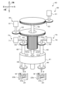
- FIG. 1 is a schematic configuration diagram of a mounting apparatus 10.
- FIG. 2 is a schematic diagram of a head 40.
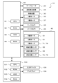
- FIG. 2 is a block diagram showing electrical connections of the mounting apparatus 10.
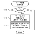
- 11 is a flowchart showing an example of a feeder position recognition process.
- 11 is a flowchart showing an example of a simultaneous adsorption process.
- FIG. 13 is an explanatory diagram showing an example of a center FC between target feeders and a center NC between target nozzles.
- FIG. 13 is an explanatory diagram showing an example of a center FC between target feeders and a center NC between target nozzles.
- FIG. 13 is an explanatory diagram showing an example of positional deviation during simultaneous chucking.
- 11 is a flowchart showing an example of a processing area setting process.
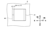
- FIG. 4 is an explanatory diagram showing an example of a reference processing area A0.
- FIG. 4 is an explanatory diagram showing an example of a processing region A1.
- FIG. 13 is an
- FIG. 1 is a schematic diagram of a mounting device 10.
- FIG. 2 is a schematic diagram of a head 40.
- FIG. 3 is a block diagram showing the electrical connections of the mounting device 10.
- the left-right direction (X-axis), front-back direction (Y-axis), and up-down direction (Z-axis) are as shown in FIG. 1.
- the mounting device 10 includes a tape feeder 20, a board transport device 24, a moving device 30, a head 40, a mark camera 25, a parts camera 26, and a control device 90 (see FIG. 3).
- a plurality of mounting devices 10 are arranged in the board transport direction (X-axis direction) to form a mounting line.
- the mounting line is managed by a management device 100 (see FIG. 3).
- the tape feeders 20 supply components to the mounting device 10, and are removably set in each slot formed in the feeder table on the front side of the mounting device 10, and are attached in a row in the X-axis direction (left and right direction).
- the tape feeder 20 includes a feeder section 21 and a reel 22 on which the tape 23 is wound.
- the tape 23 is pulled out from the reel 22 by a feed mechanism (not shown) of the feeder section 21 and sent to the component supply position.
- the tape 23 has cavities 23a (see FIG. 2) formed at predetermined intervals along its length. The cavities 23a accommodate components P.
- the components P accommodated in the cavities 23a are protected by a film covering the surface of the tape 23, and are exposed at the supply position by peeling off the film just before the supply position, and can be adsorbed by the suction nozzle 44 (adsorption member) of the head 40.
- the guide 23b that guides the tape 23 in the feed direction has a reference mark M (see FIG. 2) formed at a predetermined position on the upper surface.
- the substrate transport device 24 loads, fixes, and unloads the substrate S in the left-right direction (X-axis direction).
- the substrate transport device 24 has a pair of conveyor belts that are spaced apart from each other and span the left-right direction in FIG. 1. The substrate S is transported by these conveyor belts.
- the moving device 30 includes an X-axis slider 32 and a Y-axis slider 36, and moves the head 40 on the XY plane along the surface of the substrate S.
- the moving device 30 also includes an X-axis position sensor that detects the position of the X-axis slider 32 in the X-axis direction and a Y-axis position sensor that detects the position of the Y-axis slider 36 in the Y-axis direction, not shown.
- the X-axis slider 32 is supported by a pair of upper and lower X-axis guide rails 31 that are provided on the front surface of the Y-axis slider 36 so as to extend in the left-right direction.
- the X-axis slider 32 can be moved in the left-right direction (X-axis direction) by driving an X-axis motor 33 (see FIG. 3).
- the Y-axis slider 36 is supported by a pair of left and right Y-axis guide rails 35 that are provided on the upper stage of the housing 12 so as to extend in the front-rear direction.
- the Y-axis slider 36 can be moved in the front-rear direction (Y-axis direction) by driving a Y-axis motor 37 (see FIG. 3).
- a head 40 is attached to the X-axis slider 32. Therefore, the head 40 can be moved in the X and Y directions by the moving device 30.
- the head 40 picks up the component P supplied from the tape feeder 20 with the suction nozzle 44 and mounts it on the board S.
- the head 40 comprises a head body 41, a nozzle holder 42, a suction nozzle 44, an R-axis drive unit 50, a Q-axis drive unit 60, a first Z-axis drive unit 70, and a second Z-axis drive unit 75.
- the head 40 is configured as a rotary head in which multiple (e.g., 8, 20, 28, etc.) suction nozzles 44 are held by the head body 41.
- the head body 41 is a rotating body that can be rotated by the R-axis drive unit 50.
- the nozzle holders 42 are arranged at predetermined angular intervals in the circumferential direction relative to the head body 41, and are supported by the head body 41 so that they can be raised and lowered freely.
- a suction nozzle 44 is detachably attached to the tip of the nozzle holder 42.
- the suction nozzle 44 sucks up the component P by negative pressure supplied by a pressure supply device (not shown) through an internal flow path of the nozzle holder 42.
- the suction nozzle 44 also releases the suction of the component P by positive pressure supplied by the pressure supply device through an internal flow path of the nozzle holder 42.
- the pressure supply device is configured to include a negative pressure source, a positive pressure source, and a switching valve that can switch the pressure supplied to the suction port of each suction nozzle 44 between negative pressure, positive pressure, and atmospheric pressure, although not shown.
- the R-axis drive unit 50 rotates (revolves) the multiple nozzle holders 42 (multiple suction nozzles 44) in the circumferential direction around the central axis of the head body 41.
- the R-axis drive unit 50 includes an R-axis motor 51, an R-axis 52 extending in the axial direction from the central axis of the head body 41, a transmission gear 53 that transmits the rotation of the R-axis motor 51 to the R-axis 52, and an R-axis position sensor 55 that detects the rotation position of the R-axis motor 51.
- the R-axis drive unit 50 rotates the head body 41 by driving the R-axis 52 to rotate via the transmission gear 53 by the R-axis motor 51.
- Each nozzle holder 42 rotates (revolves) in the circumferential direction together with the suction nozzle 44 as the head body 41 rotates.
- the Q-axis drive unit 60 rotates (spins) each nozzle holder 42 (each suction nozzle 44) around its central axis.
- the Q-axis drive unit 60 includes a Q-axis motor 61, a cylindrical member 62, a transmission gear 63, a Q-axis gear 64, and a Q-axis position sensor 65 (see FIG. 3) that detects the rotational position of the Q-axis motor 61.
- the cylindrical member 62 is inserted coaxially and rotatably relative to the R-axis 52, and has a spur gear 62a formed on its outer circumferential surface.
- the transmission gear 63 transmits the rotation of the Q-axis motor 61 to the cylindrical member 62.
- the Q-axis gear 64 is provided on the upper portion of each nozzle holder 42, and engages with the spur gear 62a of the cylindrical member 62 so as to be slidable in the Z-axis direction (up and down direction).
- the Q-axis drive unit 60 rotates the cylindrical member 62 via the transmission gear 63 using the Q-axis motor 61, thereby collectively rotating each Q-axis gear 64 that meshes with the spur gear 62a of the cylindrical member 62.
- Each nozzle holder 42 rotates (spins) around its central axis together with the suction nozzle 44 due to the rotation of the Q-axis gear 64.
- the first and second Z-axis drive units 70, 75 are configured to be able to individually raise and lower the nozzle holder 42 in the Z-axis direction (lifting direction) at two lifting positions (predetermined positions) on the orbit of the nozzle holder 42.
- the first and second Z-axis drive units 70, 75 are arranged along the arrangement direction (X-axis direction) of the tape feeders 20.
- the first and second Z-axis drive devices 70, 75 include Z-axis sliders 72, 77, Z-axis motors 71, 76 that raise and lower the Z-axis sliders 72, 77, and Z-axis position sensors 74, 79 (see FIG. 3) that detect the raised and lowered positions of the Z-axis sliders 72, 77.
- the first and second Z-axis drive devices 70, 75 drive the Z-axis motors 71, 76, respectively, to raise and lower the Z-axis sliders 72, 77, thereby abutting against the nozzle holder 42 below the Z-axis sliders 72, 77, and raising and lowering the nozzle holder 42 together with the suction nozzle 44.
- the first and second Z-axis drive devices 70, 75 may use linear motors as the Z-axis motors 71, 76 to raise and lower the Z-axis sliders 72, 77, or may use a rotary motor and a ball screw mechanism to raise and lower the Z-axis sliders 72, 77.
- the head 40 is provided with two Z-axis drive devices 70, 75 that can raise and lower the nozzle holder 42 (suction nozzle 44) individually, and can perform the suction operation of the component P using the suction nozzle 44 individually.
- the head 40 can also use the two Z-axis drive devices 70, 75 to lower the two suction nozzles 44 approximately simultaneously to pick up two components P approximately simultaneously.
- the mark camera 25 is provided on the head 40 or the X-axis slider 32, and is configured to be movable in the X and Y directions by the moving device 30.
- the mark camera 25 captures images of the reference marks on the substrate S, the reference marks M on the tape feeder 20, the components P supplied to the supply position, etc. from above, and outputs the captured images to the control device 90.
- the parts camera 26 is disposed between the board transport device 24 and the tape feeder 20. When the suction nozzle 44 that has picked up the part P passes above the parts camera 26, the parts camera 26 captures an image of the part P from below, and outputs the captured image to the control device 90.
- the management device 100 is configured as a microprocessor centered on a CPU 101, and includes a ROM 102 that stores processing programs, an HDD 103 as an external storage device that stores various data, a RAM 104 used as a working area, an input/output interface, and the like.
- the external storage device is not limited to the HDD 103, and may be an SSD or the like.
- the management device 100 is connected to an input device 105 such as a keyboard and mouse through which an operator inputs various commands, and a display 106 that displays various information.
- the HDD 103 stores job information including a production program and other production information.
- the production program refers to a program that specifies which components P are to be mounted on which board S in which order in the mounting device 10, and how many boards S mounted in this manner are to be produced.
- the tape feeder 20 is removably set in each slot formed in the feeder table of the mounting device 10, and the reference position of the tape feeder 20 is determined by the pitch at which the slots are formed.
- the CPU 91 can recognize the mounting position of the tape feeder 20, including such variation, by performing a feeder position recognition process. In this embodiment, the CPU 91 recognizes the mounting position of the tape feeder 20 at least in the X-axis direction.
- the CPU 91 controls the moving device 30 so that the head 40 moves to a moving position where the center NC of the suction nozzle 44 (also called the target nozzle) that picks up the target parts to be picked up simultaneously coincides with the center FC between the target feeders (S210).
- the feeder pitch FP and the nozzle pitch NP are the same.
- the positions of the suction nozzles 44 in the head 40 are known in advance, for example, by calibration of the head 40 performed before the start of production.
- FIG. 6 shows a state in which the mounting positions Pa and Pb of the target feeders 20a and 20b are mounted at the reference position without error. Therefore, even without adjusting the position of the target nozzle (head 40), the center FC between the target feeders and the center NC between the target nozzles approximately coincide.
- FIG. 7 shows a state in which the mounting position Pb of the target feeder 20b is shifted to the right in the figure by a shift amount ⁇ from the reference position, resulting in a feeder pitch FP1 (>FP in FIG. 6). Therefore, if the target nozzle is left in the position of FIG. 6 (shown by a dotted line in FIG.
- the target nozzle (head 40) is moved to a moving position shifted to the right in FIG. 7 so that the center NC between the target nozzles coincides with the center FC between the target feeders.
- the effect of the misalignment amount ⁇ is evenly distributed to the left and right target nozzles 44a, 44b by the misalignment amount ( ⁇ /2), which reduces pickup and mounting failures compared to when the misalignment amount ⁇ is distributed to only one side.
- the head 40 is moved to a movement position where the misalignment of the target nozzle with respect to the mounting position of the target feeder is not biased toward either one of the target nozzles.
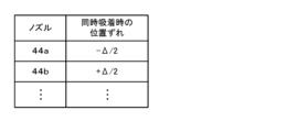
- the CPU 91 judges whether or not the suction of the target component to each target nozzle is complete (S240). If the CPU 91 judges that the suction of the target component is not complete, it rotates the head body 41 a predetermined amount to move the next target nozzle that has not yet picked up the target component above the supply position (S250), and executes the processes of S220 to S240. Therefore, each time simultaneous suction is performed by each target nozzle, a positional deviation is obtained in association with the target nozzle. On the other hand, if the CPU 91 judges that the suction of the target component is complete, it moves the head 40 above the part camera 26 and causes the part camera 26 to capture an image (target component) (S260). Next, the CPU 91 executes a processing area setting process for setting a processing area for image processing of each target component in the captured image (S270).
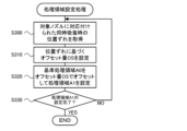
- FIG. 9 is a flow chart showing an example of the processing area setting process.
- the CPU 91 acquires the positional deviation during simultaneous pickup associated with the target nozzle that picks up the target component (S300).
- S300 the positional deviation acquired in S230 and stored in the HDD 103 (see FIG. 8) is acquired.
- the CPU 91 sets an offset amount OS based on the positional deviation during simultaneous pickup (S310), and offsets the reference processing area A0 associated with the target nozzle by the offset amount OS to set the processing area A1 of the target component (S320).
- the CPU 91 determines whether the setting of the processing area A1 has been completed for all target components in the image (S330), and if it determines that the setting has not been completed, it returns to S300, and if it determines that the setting has been completed, it ends the processing area setting process.
- the processing area A1 for the target part picked up by the target nozzle 44a is set by offsetting the reference processing area A0 to the left. In this way, the processing area A1 is set by offsetting the reference processing area A0 according to the positional deviation (amount and direction of deviation) during simultaneous pick-up.
- FIG. 12 is an explanatory diagram showing an example of a processing area A2 in the comparative example.
- the processing area A2 in the comparative example is set as an area obtained by enlarging the reference processing area A0 by adding the positional deviation ( ⁇ /2) at the time of simultaneous pickup to the left and right of the reference processing area A0 as a processing area for each target part picked up by the target nozzles 44a and 44b, for example.
- the processing area for each target part is larger than in this embodiment, and as a result, the processing time for image processing is longer.
- the head 40 is a rotary head capable of picking up multiple parts and the number of processing areas in the image G is relatively large, delays in processing time become a problem.
- the processing area A1 is set by offsetting the reference processing area A0 without enlarging it, so that the processing area A1 does not become larger than necessary, and it is possible to prevent the processing time for image processing from becoming longer.
- the CPU 91 performs image processing on the processing area A1 of each target component to recognize the suction deviation of each target component (S280).
- the CPU 91 performs image processing on the processing area A1 to recognize the target components, detect their center positions, and calculate the position deviation from the center position NO of each suction nozzle 44 in the image G to recognize the suction deviation of each target component.
- the CPU 91 corrects the mounting position of each target component based on the suction deviation and mounts the target components on the board S (S290), and ends the simultaneous suction process.
- the CPU 91 moves the head 40 so that the target components sucked by the suction nozzle 44 are positioned above the corrected mounting position, and lowers the suction nozzle 44 to mount the target components on the board S.
- the CPU 91 performs the mounting operation of S290 until the target components sucked by the multiple suction nozzles 44 are mounted.
- the control device 90 that executes S230 of the simultaneous pickup process of this embodiment corresponds to the acquisition unit of this disclosure, and the control device 90 that executes S270 of the simultaneous pickup process corresponds to the setting unit.
- the head 40 corresponds to the head
- the moving device 30 corresponds to the moving unit
- the control device 90 that executes S210 of the simultaneous pickup process corresponds to the movement control unit.
- the tape feeder 20 corresponds to the feeder
- the mark camera 25 corresponds to the imaging unit.
- an example of a processing area setting method of this disclosure is also clarified by explaining the operation of the mounting device 10.
- the positional deviation of the target nozzle relative to the mounting position of the target feeder (the supply position of the target components to be picked up simultaneously) is obtained for each target nozzle.
- a processing area A1 is set for each target component by offsetting a reference processing area A0 (predetermined area) defined in image G for each simultaneously picked up target nozzle based on the positional deviation for each target nozzle. This makes it possible to prevent the processing area A1 for image processing from becoming unnecessarily large when simultaneous pickup is performed, and therefore makes it possible to properly recognize the pickup deviation of the target components while preventing the image processing time from becoming long.
- the head 40 is moved to a movement position where the positional deviation of the target nozzles relative to the mounting position of the target feeder is not biased towards any one of the target nozzles. Then, the positional deviation of the target nozzles is obtained based on the positions of the target nozzles that perform simultaneous pickup in the head 40 that has been moved to the movement position and the mounting position of the target feeder. Therefore, when performing simultaneous pickup while preventing the positional deviation of each target nozzle relative to each supply position from being biased towards any one of the target nozzles, it is possible to prevent the processing area A1 from becoming unnecessarily large.
- the head 40 is moved to a position where the center FC between the two target feeders in the X-axis direction (predetermined direction) coincides with the center NC between the two target nozzles. This makes it possible to equalize the positional deviations of the target nozzles, stabilizing the suction of the target components while preventing the processing area A1 from becoming unnecessarily large.
- the mounting device 10 processes the image captured by the mark camera 25 to recognize the mounting position of the target feeder, and determines the movement position of the head 40 based on the recognized mounting position, and moves the head 40. Therefore, any error or positional deviation in the mounting position of the target feeder can be appropriately reflected in the setting of the processing area A1.
- each time multiple target nozzles are moved sequentially to the lifting position to perform simultaneous pickup a positional deviation corresponding to the target nozzle is obtained, and the reference processing area A0 is offset based on the positional deviation obtained corresponding to the target nozzle to set the processing area A1. Therefore, when simultaneous pickup is performed with the head 40 configured as a rotary head, the processing area A1 for each target component can be appropriately set.
- the present disclosure is applied to the setting of the processing area A1 in one image, but this is not limited to this.
- the present disclosure may be applied to the setting of the processing area in multiple images. Since super-resolution processing requires image processing of the processing areas of multiple images, offsetting and setting the processing area without enlarging it has a significant effect in shortening the processing time. For this reason, there is great significance in applying the present disclosure.
- the head 40 is a rotary head, but this is not limited to this and any configuration that allows simultaneous suction with multiple suction nozzles 44 may be used.
- a parallel-type head having multiple suction nozzles 44 arranged along the X-axis direction and each of which can be raised and lowered independently may be used.
- the head is not limited to one in which two suction nozzles 44 perform simultaneous suction, but may be one in which three or more suction nozzles 44 perform simultaneous suction.
- the CPU 91 recognizes the mounting position of the tape feeder 20 based on an image, but this is not limited thereto, and the mounting position of the tape feeder 20 may be recognized using a position detection sensor or the like. Also, while the CPU 91 recognizes the mounting position of the tape feeder 20 as the supply position of the target component, the supply position of the target component may be directly recognized by recognizing the component P from an image of the component P in the cavity 23a captured by the mark camera 25. Note that if the supply position of the target component is shifted in the Y direction, the processing area A1 may be set by offsetting the position shift in the Y direction in the same way as in the X direction.
- the head 40 is moved to a moving position where the center FC between the target feeders and the center NC between the target nozzles coincide, thereby equalizing the positional deviation during simultaneous suction for the two target nozzles, but this is not limited to the above.
- the positional deviation during simultaneous suction may be different for the two target nozzles.
- the positional deviation during simultaneous suction may remain biased toward one of the target nozzles, such as when a positional deviation occurs only in one of the target nozzles.
- simultaneous suction may be performed without adjusting the moving position of the target nozzle (head 40) while remaining biased toward one of the target nozzles. Even in such a case, by applying the present disclosure, it is possible to prevent the processing area A1 from becoming unnecessarily large when simultaneous suction is performed.
- the operation of the mounting device 10 has been described, but it may take the form of a processing area setting method for setting a processing area A1 for image processing, or an image processing method for setting a processing area A1 and performing image processing.
- the acquisition unit for acquiring the positional deviation of each suction nozzle 44 and the setting unit for setting the processing area may each be provided in separate devices.
- This disclosure can be used in technical fields such as mounting processing and image processing.
Landscapes
- Engineering & Computer Science (AREA)
- Manufacturing & Machinery (AREA)
- Microelectronics & Electronic Packaging (AREA)
- Operations Research (AREA)
- Supply And Installment Of Electrical Components (AREA)
Abstract
L'invention concerne un dispositif de montage qui utilise un élément d'aspiration pour aspirer un composant fourni à une position d'alimentation, effectue un traitement d'image sur une image capturée après l'aspiration pour reconnaître un écart d'aspiration du composant, et monte le composant après correction de l'écart d'aspiration. Le dispositif de montage comprend : une unité d'acquisition qui, lorsqu'une aspiration simultanée d'une pluralité de composants est effectuée au moyen d'une pluralité d'éléments d'aspiration, acquiert, pour chaque élément d'aspiration, un écart de position de l'élément d'aspiration par rapport à chaque position d'alimentation d'un composant cible pour une aspiration simultanée ; et une unité de réglage pour régler une région de traitement du traitement d'image pour chaque composant cible par décalage d'une région prédéterminée, qui est déterminée dans l'image pour chacun des éléments d'aspiration qui ont aspiré les composants cibles simultanément, sur la base de l'écart de position de chaque élément d'aspiration acquis par l'unité d'acquisition.
Priority Applications (4)
| Application Number | Priority Date | Filing Date | Title |
|---|---|---|---|
| DE112023006494.6T DE112023006494T5 (de) | 2023-06-13 | 2023-06-13 | Montagevorrichtung und Bearbeitungsbereichs-Einstellungsverfahren |
| CN202380099125.1A CN121264189A (zh) | 2023-06-13 | 2023-06-13 | 安装装置及处理区域设定方法 |
| JP2025526956A JPWO2024257215A1 (fr) | 2023-06-13 | 2023-06-13 | |
| PCT/JP2023/021899 WO2024257215A1 (fr) | 2023-06-13 | 2023-06-13 | Dispositif de montage et procédé de réglage de région de traitement |
Applications Claiming Priority (1)
| Application Number | Priority Date | Filing Date | Title |
|---|---|---|---|
| PCT/JP2023/021899 WO2024257215A1 (fr) | 2023-06-13 | 2023-06-13 | Dispositif de montage et procédé de réglage de région de traitement |
Publications (1)
| Publication Number | Publication Date |
|---|---|
| WO2024257215A1 true WO2024257215A1 (fr) | 2024-12-19 |
Family
ID=93851493
Family Applications (1)
| Application Number | Title | Priority Date | Filing Date |
|---|---|---|---|
| PCT/JP2023/021899 Ceased WO2024257215A1 (fr) | 2023-06-13 | 2023-06-13 | Dispositif de montage et procédé de réglage de région de traitement |
Country Status (4)
| Country | Link |
|---|---|
| JP (1) | JPWO2024257215A1 (fr) |
| CN (1) | CN121264189A (fr) |
| DE (1) | DE112023006494T5 (fr) |
| WO (1) | WO2024257215A1 (fr) |
Citations (7)
| Publication number | Priority date | Publication date | Assignee | Title |
|---|---|---|---|---|
| JPH08181495A (ja) * | 1994-12-26 | 1996-07-12 | Yamaha Motor Co Ltd | 実装機の部品認識装置 |
| JPH1065400A (ja) * | 1997-05-28 | 1998-03-06 | Yamaha Motor Co Ltd | 実装機の部品認識装置 |
| JP2003101294A (ja) * | 2001-09-20 | 2003-04-04 | Fuji Mach Mfg Co Ltd | 電気部品供給方法および電気部品装着システム |
| JP2003174286A (ja) * | 2001-12-05 | 2003-06-20 | Matsushita Electric Ind Co Ltd | 部品装着装置用の部品装着ヘッド及び部品装着方法 |
| JP2008211236A (ja) * | 2008-04-17 | 2008-09-11 | Juki Corp | 部品実装装置 |
| JP2017224779A (ja) * | 2016-06-17 | 2017-12-21 | 富士機械製造株式会社 | 実装関連処理装置 |
| JP2018093229A (ja) * | 2018-03-05 | 2018-06-14 | 株式会社Fuji | 部品実装システム |
Family Cites Families (1)
| Publication number | Priority date | Publication date | Assignee | Title |
|---|---|---|---|---|
| JP4172757B2 (ja) | 2002-07-18 | 2008-10-29 | Juki株式会社 | 部品実装装置 |
-
2023
- 2023-06-13 JP JP2025526956A patent/JPWO2024257215A1/ja active Pending
- 2023-06-13 DE DE112023006494.6T patent/DE112023006494T5/de active Pending
- 2023-06-13 WO PCT/JP2023/021899 patent/WO2024257215A1/fr not_active Ceased
- 2023-06-13 CN CN202380099125.1A patent/CN121264189A/zh active Pending
Patent Citations (7)
| Publication number | Priority date | Publication date | Assignee | Title |
|---|---|---|---|---|
| JPH08181495A (ja) * | 1994-12-26 | 1996-07-12 | Yamaha Motor Co Ltd | 実装機の部品認識装置 |
| JPH1065400A (ja) * | 1997-05-28 | 1998-03-06 | Yamaha Motor Co Ltd | 実装機の部品認識装置 |
| JP2003101294A (ja) * | 2001-09-20 | 2003-04-04 | Fuji Mach Mfg Co Ltd | 電気部品供給方法および電気部品装着システム |
| JP2003174286A (ja) * | 2001-12-05 | 2003-06-20 | Matsushita Electric Ind Co Ltd | 部品装着装置用の部品装着ヘッド及び部品装着方法 |
| JP2008211236A (ja) * | 2008-04-17 | 2008-09-11 | Juki Corp | 部品実装装置 |
| JP2017224779A (ja) * | 2016-06-17 | 2017-12-21 | 富士機械製造株式会社 | 実装関連処理装置 |
| JP2018093229A (ja) * | 2018-03-05 | 2018-06-14 | 株式会社Fuji | 部品実装システム |
Also Published As
| Publication number | Publication date |
|---|---|
| DE112023006494T5 (de) | 2026-04-23 |
| CN121264189A (zh) | 2026-01-02 |
| JPWO2024257215A1 (fr) | 2024-12-19 |
Similar Documents
| Publication | Publication Date | Title |
|---|---|---|
| JP5791408B2 (ja) | 電子部品実装装置 | |
| JP4896757B2 (ja) | 表面実装機 | |
| JP7573091B2 (ja) | 吸着位置調整装置 | |
| JP4587877B2 (ja) | 部品実装装置 | |
| JP2009212251A (ja) | 部品移載装置 | |
| JP6446282B2 (ja) | 部品実装装置、及び部品実装方法 | |
| JP6853374B2 (ja) | 部品実装機 | |
| JP6356222B2 (ja) | 部品装着装置 | |
| JP4860270B2 (ja) | 実装装置における電子部品の同時吸着の可否判定方法 | |
| JP5988839B2 (ja) | 部品実装機 | |
| JP2003347794A (ja) | 電子回路部品取出し方法および取出し装置 | |
| WO2024257215A1 (fr) | Dispositif de montage et procédé de réglage de région de traitement | |
| US11343948B2 (en) | Mounting device and mounting method | |
| US11229151B2 (en) | Component mounting machine | |
| JP3997092B2 (ja) | 電子回路部品装着機 | |
| JP3142720B2 (ja) | 実装機の位置補正方法及びその装置 | |
| CN111788878A (zh) | 元件安装装置 | |
| JP5860688B2 (ja) | 対基板作業機 | |
| JP7446499B2 (ja) | 部品実装機 | |
| JPWO2016157287A1 (ja) | 部品実装機 | |
| WO2020148901A1 (fr) | Dispositif de montage de composant | |
| EP3813503B1 (fr) | Dispositif de montage de composants électroniques et procédé de commande | |
| JP6600570B2 (ja) | 部品実装装置 | |
| WO2018158904A1 (fr) | Dispositif de montage de composant et procédé de traitement d'image | |
| WO2021002005A1 (fr) | Machine de montage de composant |
Legal Events
| Date | Code | Title | Description |
|---|---|---|---|
| 121 | Ep: the epo has been informed by wipo that ep was designated in this application |
Ref document number: 23941523 Country of ref document: EP Kind code of ref document: A1 |
|
| ENP | Entry into the national phase |
Ref document number: 2025526956 Country of ref document: JP Kind code of ref document: A |
|
| WWE | Wipo information: entry into national phase |
Ref document number: 2025526956 Country of ref document: JP |
|
| WWE | Wipo information: entry into national phase |
Ref document number: 112023006494 Country of ref document: DE |