WO2024257236A1 - Endoscope, capuchon d'endoscope - Google Patents
Endoscope, capuchon d'endoscope Download PDFInfo
- Publication number
- WO2024257236A1 WO2024257236A1 PCT/JP2023/021963 JP2023021963W WO2024257236A1 WO 2024257236 A1 WO2024257236 A1 WO 2024257236A1 JP 2023021963 W JP2023021963 W JP 2023021963W WO 2024257236 A1 WO2024257236 A1 WO 2024257236A1
- Authority
- WO
- WIPO (PCT)
- Prior art keywords
- endoscope
- sensor
- pressure
- tip
- cap
- Prior art date
- Legal status (The legal status is an assumption and is not a legal conclusion. Google has not performed a legal analysis and makes no representation as to the accuracy of the status listed.)
- Ceased
Links
Images








Classifications
-
- A—HUMAN NECESSITIES
- A61—MEDICAL OR VETERINARY SCIENCE; HYGIENE
- A61B—DIAGNOSIS; SURGERY; IDENTIFICATION
- A61B1/00—Instruments for performing medical examinations of the interior of cavities or tubes of the body by visual or photographical inspection, e.g. endoscopes; Illuminating arrangements therefor
- A61B1/00064—Constructional details of the endoscope body
- A61B1/00071—Insertion part of the endoscope body
- A61B1/0008—Insertion part of the endoscope body characterised by distal tip features
- A61B1/00097—Sensors
-
- A—HUMAN NECESSITIES
- A61—MEDICAL OR VETERINARY SCIENCE; HYGIENE
- A61B—DIAGNOSIS; SURGERY; IDENTIFICATION
- A61B1/00—Instruments for performing medical examinations of the interior of cavities or tubes of the body by visual or photographical inspection, e.g. endoscopes; Illuminating arrangements therefor
-
- A—HUMAN NECESSITIES
- A61—MEDICAL OR VETERINARY SCIENCE; HYGIENE
- A61B—DIAGNOSIS; SURGERY; IDENTIFICATION
- A61B1/00—Instruments for performing medical examinations of the interior of cavities or tubes of the body by visual or photographical inspection, e.g. endoscopes; Illuminating arrangements therefor
- A61B1/00002—Operational features of endoscopes
- A61B1/00004—Operational features of endoscopes characterised by electronic signal processing
- A61B1/00006—Operational features of endoscopes characterised by electronic signal processing of control signals
-
- A—HUMAN NECESSITIES
- A61—MEDICAL OR VETERINARY SCIENCE; HYGIENE
- A61B—DIAGNOSIS; SURGERY; IDENTIFICATION
- A61B1/00—Instruments for performing medical examinations of the interior of cavities or tubes of the body by visual or photographical inspection, e.g. endoscopes; Illuminating arrangements therefor
- A61B1/00002—Operational features of endoscopes
- A61B1/00043—Operational features of endoscopes provided with output arrangements
- A61B1/00045—Display arrangement
-
- A—HUMAN NECESSITIES
- A61—MEDICAL OR VETERINARY SCIENCE; HYGIENE
- A61B—DIAGNOSIS; SURGERY; IDENTIFICATION
- A61B1/00—Instruments for performing medical examinations of the interior of cavities or tubes of the body by visual or photographical inspection, e.g. endoscopes; Illuminating arrangements therefor
- A61B1/00112—Connection or coupling means
- A61B1/00114—Electrical cables in or with an endoscope
-
- A—HUMAN NECESSITIES
- A61—MEDICAL OR VETERINARY SCIENCE; HYGIENE
- A61B—DIAGNOSIS; SURGERY; IDENTIFICATION
- A61B1/00—Instruments for performing medical examinations of the interior of cavities or tubes of the body by visual or photographical inspection, e.g. endoscopes; Illuminating arrangements therefor
- A61B1/00131—Accessories for endoscopes
- A61B1/00137—End pieces at either end of the endoscope, e.g. caps, seals or forceps plugs
-
- A—HUMAN NECESSITIES
- A61—MEDICAL OR VETERINARY SCIENCE; HYGIENE
- A61B—DIAGNOSIS; SURGERY; IDENTIFICATION
- A61B1/00—Instruments for performing medical examinations of the interior of cavities or tubes of the body by visual or photographical inspection, e.g. endoscopes; Illuminating arrangements therefor
- A61B1/005—Flexible endoscopes
-
- A—HUMAN NECESSITIES
- A61—MEDICAL OR VETERINARY SCIENCE; HYGIENE
- A61B—DIAGNOSIS; SURGERY; IDENTIFICATION
- A61B1/00—Instruments for performing medical examinations of the interior of cavities or tubes of the body by visual or photographical inspection, e.g. endoscopes; Illuminating arrangements therefor
- A61B1/012—Instruments for performing medical examinations of the interior of cavities or tubes of the body by visual or photographical inspection, e.g. endoscopes; Illuminating arrangements therefor characterised by internal passages or accessories therefor
- A61B1/018—Instruments for performing medical examinations of the interior of cavities or tubes of the body by visual or photographical inspection, e.g. endoscopes; Illuminating arrangements therefor characterised by internal passages or accessories therefor for receiving instruments
-
- A—HUMAN NECESSITIES
- A61—MEDICAL OR VETERINARY SCIENCE; HYGIENE
- A61B—DIAGNOSIS; SURGERY; IDENTIFICATION
- A61B90/00—Instruments, implements or accessories specially adapted for surgery or diagnosis and not covered by any of the groups A61B1/00 - A61B50/00, e.g. for luxation treatment or for protecting wound edges
- A61B90/06—Measuring instruments not otherwise provided for
-
- A—HUMAN NECESSITIES
- A61—MEDICAL OR VETERINARY SCIENCE; HYGIENE
- A61B—DIAGNOSIS; SURGERY; IDENTIFICATION
- A61B90/00—Instruments, implements or accessories specially adapted for surgery or diagnosis and not covered by any of the groups A61B1/00 - A61B50/00, e.g. for luxation treatment or for protecting wound edges
- A61B90/06—Measuring instruments not otherwise provided for
- A61B2090/064—Measuring instruments not otherwise provided for for measuring force, pressure or mechanical tension
-
- A—HUMAN NECESSITIES
- A61—MEDICAL OR VETERINARY SCIENCE; HYGIENE
- A61B—DIAGNOSIS; SURGERY; IDENTIFICATION
- A61B2560/00—Constructional details of operational features of apparatus; Accessories for medical measuring apparatus
- A61B2560/04—Constructional details of apparatus
- A61B2560/0462—Apparatus with built-in sensors
-
- A—HUMAN NECESSITIES
- A61—MEDICAL OR VETERINARY SCIENCE; HYGIENE
- A61B—DIAGNOSIS; SURGERY; IDENTIFICATION
- A61B2562/00—Details of sensors; Constructional details of sensor housings or probes; Accessories for sensors
- A61B2562/02—Details of sensors specially adapted for in-vivo measurements
- A61B2562/0247—Pressure sensors
-
- A—HUMAN NECESSITIES
- A61—MEDICAL OR VETERINARY SCIENCE; HYGIENE
- A61B—DIAGNOSIS; SURGERY; IDENTIFICATION
- A61B2562/00—Details of sensors; Constructional details of sensor housings or probes; Accessories for sensors
- A61B2562/04—Arrangements of multiple sensors of the same type
- A61B2562/043—Arrangements of multiple sensors of the same type in a linear array
-
- A—HUMAN NECESSITIES
- A61—MEDICAL OR VETERINARY SCIENCE; HYGIENE
- A61B—DIAGNOSIS; SURGERY; IDENTIFICATION
- A61B2562/00—Details of sensors; Constructional details of sensor housings or probes; Accessories for sensors
- A61B2562/22—Arrangements of medical sensors with cables or leads; Connectors or couplings specifically adapted for medical sensors
- A61B2562/225—Connectors or couplings
- A61B2562/227—Sensors with electrical connectors
Definitions
- This invention relates to an endoscope and an endoscope cap.
- endoscopes have been widely used in, for example, the medical and industrial fields.
- Medical endoscopes used in the medical field have a function of inserting an insertion section equipped with an imaging unit into the inside of a body cavity or organ of a subject such as a living organism, and acquiring images of an object to be observed, including lesions within the body cavity or organ.
- the images acquired in this way are used for image diagnosis, etc., to observe or inspect lesions, etc.
- Endoscopic examinations using conventional medical endoscopes include, for example, upper gastrointestinal endoscopy, which mainly observes, examines and treats the inside of the upper gastrointestinal tract, such as the esophagus, stomach and duodenum, and colonoscopy, which mainly observes, examines and treats the inside of the lumen of the large intestine, and these types of endoscopic examinations are widely performed.
- upper gastrointestinal endoscopy which mainly observes, examines and treats the inside of the upper gastrointestinal tract, such as the esophagus, stomach and duodenum
- colonoscopy which mainly observes, examines and treats the inside of the lumen of the large intestine
- an insertion operation is performed in which the tip component of the insertion part is inserted into a lumen from the oral cavity or anus, etc., and advanced deeper along the lumen.
- This insertion operation includes specific operations such as actively bending the bending part of the insertion part by performing a specific bending operation as necessary, or twisting the insertion part.
- endoscopic image data is continuously acquired by the imaging unit provided at the tip component of the insertion part, and specific image processing is performed. Images generated based on the endoscopic image data are then continuously displayed on the display device. This allows a user such as a surgeon (hereinafter referred to as the surgeon, etc.) to observe the endoscopic images in real time.
- the insertion operation of the insertion part at this time may be performed while, for example, the tip component of the insertion part is pressed against the inner wall of the lumen.
- the load applied to the inner wall when the tip component is pressed against the inner wall i.e., the amount of pressing force or load force (hereinafter simply referred to as force) is usually adjusted by the surgeon while checking the endoscopic image and based on the feel of his/her fingers.
- organs and other objects to be observed and examined are arranged in a complex manner within a living subject, and there are many bent parts. Furthermore, it is known that organs and other objects do not always maintain a constant shape within a subject, and that their shape is constantly changing depending on, for example, the subject's posture.
- the insertion operation during endoscopic examination in which the insertion part is inserted into the interior of organs, etc., which are arranged in a complex manner and cannot be directly viewed, tends to depend on the skill of the surgeon, etc.
- the tip component is pressed against the inner wall of an organ, etc., with excessive force during the insertion operation, it may cause a burden on the subject (patient, etc.) and affect the organ, etc.
- the technology disclosed in the above-mentioned International Patent Publication WO2021/176530 and the like is an endoscope hood that is attached to the tip component of the insertion part of an endoscope, and this endoscope hood has a main body part consisting of a hood part that is located further towards the tip than the insertion part and an attachment part that fits around the outer periphery of the insertion part, and a pressure sensor provided on the attachment part.
- the hood cap type pressure sensor for an endoscope disclosed in the above-mentioned Patent Publication No. 2016-152863 is provided on the outer surface of a cylindrical hood with high rigidity, and the pressure sensor is composed of multiple sensors in order to measure a fine pressure distribution. As a result, there is a problem in that the number of wirings extending from the multiple sensors becomes large.
- the endoscope hood of the endoscope disclosed in the above-mentioned International Patent Publication WO2021/176530 and the like is formed of a hard hood portion provided on the tip side of the insertion portion, and a soft mounting portion that fits around the outer periphery of the insertion portion.
- a single pressure-sensitive portion (sensor element) is embedded in the mounting portion.
- the hood portion is hard and has high rigidity, it comes into contact with the inner wall surface of the lumen, and if a large force is applied to the insertion portion, the force transmitted from the tip component to the inner wall surface of the lumen may become strong.
- the conventional endoscope hoods disclosed in the above-mentioned Patent Publication No. 2016-152863, International Patent Publication No. WO2021/176530, etc. are all attachment-type, so the wiring extending from each sensor extends along the outer surface of the insertion section to the operating section. The wiring is then fixed to the outer surface of the insertion section using adhesive or the like.
- the present invention aims to provide an endoscope and an endoscope cap that can reliably and accurately detect the amount of load applied to the tip component of the insertion section of the endoscope, and that is configured to reduce the impact on an organ, etc., even if the tip component is pressed against the inner wall surface of an organ, etc.
- an endoscope includes an insertion section and a pressure sensor, the pressure sensor being disposed inside the insertion section at a location near the tip, and the rigidity of a first region of the insertion section, including the internal contact surfaces with which the pressure-sensitive sensor sections of the pressure sensor are in contact, is higher than the rigidity of a second region of the insertion section, including the outer surface of the insertion section.
- An endoscopic cap is an endoscopic cap that is attached to the tip of an insertion section of an endoscope, and has an internal pressure sensor, with the rigidity of a first region including an internal contact surface with which the pressure-sensitive sensor section of the pressure sensor comes into contact being higher than the rigidity of a second region including an outer surface.
- the present invention provides an endoscope and an endoscope cap that can reliably and accurately detect the amount of load applied to the tip component of the insertion section of the endoscope, and that is configured to reduce the impact on an organ, etc., even if the tip component is pressed against the inner wall surface of an organ, etc.
- FIG. 1 is a schematic diagram showing an overall configuration of an endoscope system including an endoscope according to a first embodiment of the present invention
- FIG. 2 is an external perspective view showing an enlarged view of a distal end portion of an insertion portion of an endoscope according to a first embodiment of the present invention
- FIG. 3 is a vertical cross-sectional view taken along a virtual plane indicated by arrow [3] in FIG.
- FIG. 3 is a front view taken in the direction indicated by the arrow [4] in FIG.
- FIG. 1 is a conceptual diagram showing an operation of the endoscope according to the first embodiment of the present invention, illustrating a state in which an insertion portion is inserted into a subject;
- FIG. 5 is a conceptual diagram showing a cross section along the curve indicated by the reference numeral [10] in FIG.
- FIG. 11 is an exploded perspective view showing an enlarged view of an endoscope cap according to a second embodiment of the present invention and a distal end portion of an insertion section to which the endoscope cap is attached;
- FIG. 1 is a conceptual diagram showing an operation of the endoscope according to the first embodiment of the present invention, illustrating a state in which an insertion portion is inserted into a subject
- FIG. 5 is a conceptual diagram showing a cross section along the curve indicated by the reference numeral [10] in FIG.
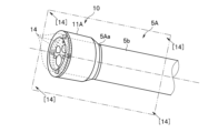
- FIG. 13 is an external perspective view showing a state in which the endoscope cap of FIG. 12 is attached to the distal end portion of the insertion portion.
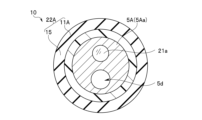
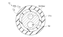
- FIG. 14 is a vertical cross-sectional view taken along an imaginary plane indicated by arrow [14] in FIG. 15 is a cross-sectional view taken along the line indicated by the arrow [15] in FIG. 15 is a cross-sectional view taken along the line indicated by the arrow [16] in FIG. 15 is a cross-sectional view taken along the line indicated by the arrow [17] in FIG. 15 is a cross-sectional view taken along the line indicated by the arrow [18] in FIG. 15 is a cross-sectional view taken along the line indicated by the arrow [19] in FIG.
- FIG. 1 is a schematic diagram showing the overall configuration of the endoscope system including the endoscope according to the first embodiment of the present invention.
- the endoscope system 1 is configured to include an endoscope 2, a light source device 3, a processor 4, and a monitor 8. Note that this endoscope system 1 is an example of a colonoscopic examination for observing the inside of a subject's (patient's) colon.
- the basic configuration of the endoscope system 1 shown in FIG. 1 is substantially the same as that of a conventional endoscope system of the same type.
- the endoscope 2 is composed of an insertion section 5, an operating section 6, a universal cord 7, etc.
- the insertion section 5 is a component that is inserted into a subject such as a living organism.
- the insertion section 5 is formed by connecting, in order from the tip side, a tip component section 5a, a curved section 5b, and a flexible tube section 5c.
- the insertion section 5 is formed in a generally elongated tube shape.
- the insertion section 5 has an internal treatment tool insertion channel 5d, which is a conduit for inserting an endoscopic treatment tool (not shown). This treatment tool insertion channel 5d is provided so as to pass through the insertion section 5 from its tip to its base end.
- the operation section 6 is connected to the base end side of the insertion section 5.
- the imaging unit is an electronic device unit consisting of a photoelectric conversion element and an optical lens (imaging lens) that acquires image information (still images and moving images) of an internal observation object of the subject (for example, the inner wall surface of an organ such as the large intestine).
- the illumination unit is a component unit including an optical element (illumination lens) that emits a light beam guided from the light source device 3 forward from the tip surface of the tip component 5a to illuminate an observation target area including a lesion in the subject. Details of the internal configuration of the tip component 5a of the insertion section 5 in the endoscope 2 of this embodiment will be described later.
- the operating section 6 is connected to the base end of the insertion section 5.
- the operating section 6 is composed of an operating section main body 6a, a bending operation knob 6b, multiple operating members 6c, a treatment tool insertion port 6d, etc.
- the operating unit body 6a has a generally box-like shape overall and constitutes a gripping section that is held by the surgeon or other user of the endoscope 2. As described above, the insertion section 5 extends from the operating unit body 6a.
- the bending operation knob 6b and the multiple operation members 6c are operation members for performing various operations of the endoscope 2.
- the bending operation knob 6b and the multiple operation members 6c are each provided at a predetermined position on the outer surface of the operation unit main body 6a.
- the treatment tool insertion port 6d is provided at a predetermined position near the tip of the operating unit main body 6a.
- the treatment tool insertion port 6d is the proximal opening of the treatment tool insertion channel 5d of the insertion section 5.
- the treatment tool insertion channel 5d is connected to the channel opening 5e (not shown in Figure 1; see Figure 2, etc., described later) which is the tip opening of the tip component 5a on the tip side.
- an endoscopic treatment tool (not shown) inserted through the treatment tool insertion port 6d can be inserted through the treatment tool insertion channel 5d and then protruded outward from the channel opening 5e of the tip component 5a.
- the universal cord 7 is a connection cord for connecting the endoscope 2 to the light source device 3 and the processor 4. To this end, the universal cord 7 is made of a tubular member extending from the side of the operation unit body 6a of the operation unit 6. A scope connector 7a is provided at the tip of the universal cord 7. This scope connector 7a is connected to the front panel of the light source device 3.
- An electrical cable 7b extends from the scope connector 7a.
- a connector 7c is provided at the end of this electrical cable 7b. This connector 7c is connected to the front panel of the processor 4.
- Various signal transmission cables, optical fiber cables, etc. (not shown) are inserted into the universal cord 7.
- the light source device 3 is a device that supplies illumination light to an illumination unit provided inside the tip component 5a of the insertion section 5 of the endoscope 2.
- the illumination light emitted from the light source device 3 is transmitted to the illumination unit of the tip component 5a through an optical fiber cable (not shown) that is inserted from the scope connector 7a through the universal cord 7, the operation section 6, and the insertion section 5.
- the illumination light then passes through an illumination lens, etc. included in the illumination unit of the tip component 5a, and is irradiated toward the observation target area in front of the tip component 5a.
- the processor 4 is a control device and signal processing device that includes a control circuit and a signal processing circuit that control the entire endoscope system 1.
- the control circuit in the processor 4 receives, for example, an operation instruction signal from the operation member 6c of the operation section 6 of the endoscope 2, and outputs various control signals for driving and controlling, for example, the imaging unit, the light source device, or the lighting unit.
- the signal processing circuit receives, for example, an imaging signal from the imaging unit provided inside the tip component 5a of the insertion section 5 of the endoscope 2, and performs predetermined image signal processing, etc.
- the processor 4 and the imaging unit are electrically connected by a signal transmission cable (not shown).
- the signal transmission cable is inserted through the connector 7c, the electrical cable 7b, the scope connector 7a, the universal cord 7, the operation section 6, the insertion section 5, and then through to the imaging unit of the tip configuration section 5a.
- One form of signal transmission cable is a composite cable in which multiple cables are bundled together and covered with an outer shield, outer tube, etc.
- the monitor 8 is a display device that receives image signals output from the processor 4 and displays endoscopic images and various types of information in a predetermined format. To achieve this, the monitor 8 and the processor 4 are electrically connected using a video cable 9 in a predetermined format.
- the monitor 8 may be in the form of a display device that is configured using, for example, a general liquid crystal panel.
- the light source device 3 and the processor 4 are not limited to being configured separately, as in the example configuration shown in FIG. 1.
- the light source device 3 and the processor 4 may be configured as an integrated unit.
- the configuration example of the lighting unit is not limited to the above-mentioned configuration example (a form in which the lighting light from the light source device is transmitted to the tip component through an optical fiber cable or the like).
- a light-emitting element such as an LED (Light Emitting Diode) as a lighting light source can be provided inside the tip component, and the power supply to the lighting light source (LED) and its light emission control can be controlled by a control circuit of the processor 4.
- Figs. 2 to 8 are external perspective views showing an enlarged view of the tip portion of the insertion section in the endoscope of this embodiment.
- Fig. 2 is an external perspective view of the tip portion of the insertion section.
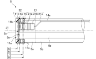
- Fig. 3 is a vertical cross-sectional view along an imaginary plane indicated by arrow [3] in Fig. 2.
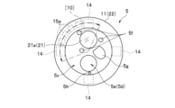
- Fig. 4 is a front view seen from the direction indicated by arrow [4] in Fig. 2.
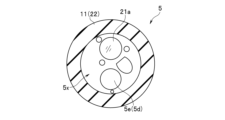
- Fig. 5 is a cross-sectional view along the line indicated by arrow [5] in Fig. 3.
- Fig. 3 is a vertical cross-sectional view along an imaginary plane indicated by arrow [3] in Fig. 2.
- Fig. 4 is a front view seen from the direction indicated by arrow [4] in Fig. 2.
- Fig. 5 is a cross-sectional view along the line indicated by arrow [5] in Fig. 3.
- FIG. 6 is a cross-sectional view along the line indicated by arrow [6] in Fig. 3.
- Fig. 7 is a cross-sectional view along the line indicated by arrow [7] in Fig. 3.
- Fig. 8 is a cross-sectional view along the line indicated by arrow [8] in Fig. 3.
- the tip component 5a of the insertion section 5 in the endoscope 2 of this embodiment is provided with an imaging unit 21, a lighting unit (not shown), a treatment tool insertion channel 5d (part of it), a load detection unit 22 (see Figure 3), etc.
- the imaging unit 21 is a component unit that includes an imaging lens 21a, an imaging element 21b, a signal transmission cable 21c, etc., and acquires a desired image.
- the illumination unit is a component unit that includes an illumination lens 5f shown in FIG. 4, etc., and illuminates an object.
- the treatment tool insertion channel 5d is a hollow tubular member that has a channel opening 5e at its tip and passes through the inside of the insertion section 5 to the inside of the operation section 6.
- the imaging unit 21, lighting unit, and treatment tool insertion channel 5d are configured in substantially the same manner as those used in conventional endoscopes of the same type. Therefore, detailed descriptions of these components will be omitted.
- the front surface 5x of the tip component 5a is provided with various components such as an imaging lens 21a which is part of the imaging unit 21, an illumination lens 5f which is part of the illumination unit, an air/water supply nozzle 5g, an auxiliary water supply port 5h, and a channel opening 5e.
- the load detection unit 22 is disposed at the tip of the tip component 5a, and is a component unit that detects the amount of force (load) applied to the tip of the insertion section 5. As shown in Figures 2 and 3, the load detection unit 22 is configured to include a tip cap 11, a rigid ring 13, multiple pressure sensors 14, and a sensor board 15.
- the tip cap 11 is an exterior member that mainly covers the side and part of the front (outer peripheral edge) near the tip of the outer surface of the tip component 5a, and forms part of the outer surface of the insertion section 5.
- the tip cap 11 has a generally cylindrical shape.
- An inward flange 11b with a first opening 11a is formed at one end (tip side) of the tip cap 11.
- a second opening 11c is formed at the other end (base end side) of the tip cap 11.
- the first opening 11a and the second opening 11c are connected by a through hole that penetrates the tip cap 11.
- the first opening 11a has a size (area) that can expose, without obstructing, the front faces of all of the various components (imaging lens 21a, illumination lens 5f, air/water supply nozzle 5g, auxiliary water supply port 5h, channel opening 5e, etc.) arranged on the front face 5x of the tip component 5a.
- the tip cap 11 is formed using a flexible material with low rigidity (e.g., rubber material, etc.).
- the rigid ring 13, pressure sensor 14, and sensor board 15 are arranged in order from the tip side toward the base end. These components (rigid ring 13, pressure sensor 14, and sensor board 15) are located inside the tip component 5a of the insertion section 5, near the tip.
- the rigid ring 13 is a member having an approximately circular ring shape overall.
- the outer peripheral surface of the rigid ring 13 is disposed along the inner wall surface of the side of the tip cap 11.
- the front end surface of the rigid ring 13 is disposed in contact with the inner surface of the inward flange 11b of the tip cap 11.
- the front end surface of the rigid ring 13 is integrally fixed to the inner surface of the inward flange 11b, for example, by adhesive.
- the rigid ring 13 is disposed near the tip of the tip component 5a and in the vicinity of the outer peripheral edge.
- the rigid ring 13 is formed using a hard material with high rigidity (for example, a metal material such as SUS or a hard resin). Therefore, the rigid ring 13 is configured to have a rigidity higher than that of the tip cap 11.
- the rigid ring 13 is configured to have a thickness dimension of approximately 0.005 mm to 3 mm and a diameter dimension of approximately 5 mm to 20 mm.
- the pressure sensor 14 is a sensor device that is disposed inside the insertion portion 5 (inside the tip cap 11) near the tip and detects pressure applied to the tip component 5a.
- Multiple pressure sensors 14 are mounted on the mounting surface of the sensor board 15.
- the sensor pressure sensing portion (front surface) of the pressure sensor 14 is disposed facing the rear end surface of the rigid ring 13. At this time, there is almost no gap between the sensor pressure sensing portion of the pressure sensor 14 and the rear end surface of the rigid ring 13 (i.e., almost in contact), or they are disposed facing each other with a small gap (e.g., about 0.1 mm).
- the front end surface of the rigid ring 13 is fixed integrally to the inner surface of the inward flange 11b of the tip cap 11.
- the rear end surface of the rigid ring 13 is disposed in contact with a position facing the sensor pressure sensing portion of the pressure sensor 14.
- the surface that contacts the sensor pressure sensing portion of the pressure sensor 14 is referred to as the internal contact surface.
- a predetermined area including the rigid ring 13 is referred to as a first area. Furthermore, in the tip cap 11, a predetermined area including the outer surface is referred to as a second area.
- the tip cap 11 of the insertion portion 5 is set so that the rigidity of a first region including the internal contact surface (rigidity ring 13) with which each pressure-sensitive sensor portion of the pressure sensor 14 comes into contact is higher than the rigidity of a second region including the outer surface of the tip cap 11 of the insertion portion 5.
- the rigidity ring 13, which is the contact member is higher than the second region.
- the sensor pressure sensing portion of the pressure sensor 14 contacts the rear end surface of the rigid ring 13. Therefore, in this configuration example, the internal contact surface is the rear end surface of the rigid ring 13.
- the rigid ring 13 is a contact member provided at a position where the sensor pressure sensing portion of the pressure sensor 14 contacts.
- the rigid ring 13, which is a contact member is disposed between the internal contact surface and the sensor pressure sensing portion. And, with this configuration, the force applied to the outer surface of the insertion portion 5 (tip cap 11) is transmitted to the sensor pressure sensing portion of the pressure sensor 14 through the rigid ring 13, which is a contact member.
- the pressure sensors 14 are arranged at approximately equal intervals in the circumferential direction around the central axis J1 of the tip cap 11. At least two pressure sensors 14 should be provided.
- pressure sensors 14 are arranged at approximately equal intervals in the circumferential direction around the central axis J1 of the tip cap 11.
- a piezoelectric element is used as the pressure sensor 14.
- the sensor board 15 has a generally circular ring shape, with its outer periphery arranged along the inner surface of the side of the tip cap 11.
- the pressure sensor 14 is mounted on the mounting surface (front side) of the sensor board 15.
- an electronic circuit e.g., an AD conversion circuit, etc. that receives the output signal of the pressure sensor 14 and performs a predetermined signal processing is also mounted on the same mounting surface of the sensor board 15.
- a signal cable 14a extends from the pressure sensor 14 (the sensor board 15 on which it is mounted) towards the base end of the insertion section 5.
- the signal cable 14a passes through the inside of the insertion section 5 together with other signal transmission cables 21c and the like.
- the signal cable 14a passes from the insertion section 5 through the operation section 6, universal cord 7, scope connector 7a, electrical cable 7b, and connector 7c, and is connected to the processor 4. In this way, the output signal of the pressure sensor 14 is transmitted to the processor 4.
- the tip component 5a is configured to include a load detection unit 22.
- the endoscope 2 functions as a detection device that detects the amount of force (load) applied mainly toward the front surface 5x of the insertion portion 5.
- the insertion section 5 of the endoscope 2 in the endoscope system 1 shown in FIG. 1 is inserted into the subject, such as a patient, to be examined according to normal examination procedures (not shown).
- FIG. 9 is a diagram showing the operation of the endoscope 2 of the first embodiment of the present invention, and is a conceptual diagram showing the state in which the insertion portion 5 is inserted into the subject.
- the insertion section 5 of the endoscope 2 is inserted inside the lumen of an organ 100, such as the large intestine.
- the surgeon, etc. performs a predetermined insertion operation using the bending operation knob 6b, etc. of the operation section 6, while performing an operation to advance the insertion section 5 along the inside of the lumen of the subject's organ, etc.
- the tip of the insertion section 5 When the insertion section 5 is inserted along the inside of a lumen of an organ, for example, the tip of the insertion section 5 may come into contact with the inner wall of the subject's organ, as shown in Figure 9. In this case, if the insertion operation of the insertion section 5 is continued, the tip of the insertion section 5 will be pressed with a strong force against the inner wall of the organ.
- the state shown in Figure 9 shows the state in which the tip of the insertion section 5 comes into contact with a part of the inner wall of the subject's organ (the part indicated by the symbol [A] in Figure 9).
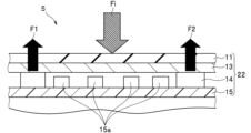
- FIG. 10 is a conceptual diagram showing an expanded cross section along the curve indicated by reference numeral [10] in FIG. 4.
- the amount of force applied to the tip of the insertion section 5 is indicated by the arrow Fi.
- This amount of force Fi is first applied to the outer surface of the tip cap 11.
- This amount of force Fi then presses against the inward flange 11b.
- the tip cap 11 (inward flange 11b) is made of a flexible material with low rigidity. Therefore, even if the outer surface of the tip of the insertion section 5 abuts against and presses against the inner wall surface of the organ 100, there is little effect on the inner wall surface.
- the rigid ring 13 is made of a hard material that is more rigid than the tip cap 11. Therefore, when the force Fi is transmitted to the rigid ring 13, the rigid ring 13 as a whole is pushed in the same direction as the force Fi (the direction of the arrow Fi in Figure 10). As a result, the rigid ring 13 presses against the sensor pressure sensing portion of the pressure sensor 14.
- the force Fi applied to the outer surface of the tip cap 11 acts, for example, at a position corresponding to the position where the pressure sensor 14 is located, the force Fi passes through the rigid ring 13 and presses against the sensor pressure sensing portion of the pressure sensor 14 that corresponds to the straight.
- the force Fi applied to the outer surface of the tip cap 11 acts, for example, at any position in the intermediate region relative to the positions where the two pressure sensors 14 are disposed, the force Fi passes through the rigid ring 13 and presses the sensor pressure sensing parts of the two pressure sensors 14 with a predetermined force.
- the position at which the force acts around the central axis J1 of the insertion portion 5 can also be detected based on the output signals F1 and F2 of the two pressure sensors 14.
- reaction forces F1 and F2 of each pressure sensor 14 are, for example, F1>F2.
- the output signals of each pressure sensor 14 are then transmitted to the processor 4 via the signal cables 14a.
- the processor 4 performs predetermined signal processing based on the input output signals of each pressure sensor 14. In this way, predetermined display information is generated.
- the generated display information is then output to the monitor 8. In response, the monitor 8 displays the various pieces of information generated based on the output signals of the pressure sensors 14.
- FIG. 11 is a conceptual diagram of the display screen displayed on the monitor 8 during an examination such as a colonoscopy performed using the endoscope system 1 of FIG. 1.
- the display screen 8a of the monitor 8 shows a real-time endoscopic image 101 being acquired by the endoscope 2, and examples of various pieces of information generated based on the output signals of each pressure sensor 14.
- Examples of information displays shown in FIG. 11 include a distribution display of the force applied to the tip of the insertion portion 5 (see reference numeral 102 in FIG. 11), a guide display for the insertion operation of the insertion portion 5 (see reference numeral 103 in FIG. 11), and an iconized display of the guide display for the insertion operation of the insertion portion 5 (see reference numeral 104 in FIG. 11).
- the force distribution display 102 displays, in the form of an icon, the force distribution on the tip surface when viewed from the tip of the insertion section 5.
- an icon the force distribution on the tip surface when viewed from the tip of the insertion section 5.
- four regions are shown around the tip surface of the insertion section 5. Of these four regions, the region that includes the region to which force is being applied is displayed in a predetermined color (cross-hatching is used to display the color in FIG. 11).
- this embodiment shows an example configuration in which four pressure sensors 14 are provided inside the tip configuration portion 5a of the insertion portion 5. For this reason, the force distribution display 102 in FIG. 11 shows four regions corresponding to the four pressure sensors 14.
- the multiple display areas corresponding to the two pressure sensors 14 near the action position can be displayed in a predetermined color, etc., to display the action position (direction of force) around the central axis of the insertion part 5. Furthermore, at this time, the action position display can be made clearer by, for example, displaying the multiple display areas in a shade of gray according to the distance from the action position of the pressure sensor 14.
- the outer surface of the insertion part 5 is configured with a tip cap 11 made of a flexible material with low rigidity, and a rigid ring 13 made of a hard material with high rigidity is provided at the portion where the sensor sensitive part of the pressure sensor 14 comes into contact.
- a rigid ring 13 is provided between the rear end surface of the inward flange 11b of the tip cap 11 and the sensor pressure sensing portion of the pressure sensor 14, and a predetermined gap is provided between the internal contact surface of the rigid ring 13 and the multiple electronic components 15a.
- the rigid ring 13 (contact member) is disposed across each sensor pressure sensing portion of at least two pressure sensors 14.
- a predetermined gap is provided between a surface parallel to the sensor pressure sensing portion and the mounting surface of the sensor board 15 on which the pressure sensor 14 is mounted.
- the multiple electronic components 15a are disposed within the range of the predetermined gap.
- the force Fi applied to the outer surface of the tip cap 11 is received by the rigid ring 13.
- the force Fi does not affect the multiple electronic components 15a. Therefore, the force Fi does not damage the electronic circuits on the sensor board 15, which includes the multiple electronic components 15a.
- the output signal of the pressure sensor 14 is also transmitted to the processor 4, where it is subjected to a predetermined signal processing before being sent to the monitor 8.
- the information acquired based on the output signal of the pressure sensor 14 is disclosed to the surgeon, etc. through the display on the monitor 8. This allows the surgeon, etc. to properly perform the insertion operation of the insertion portion 5 while looking at the displayed information on the monitor 8. This can therefore contribute to smoother insertion operation of the insertion portion 5 and improved operability.
- the above-mentioned first embodiment is a configuration example in which the tip component 5a of the insertion section 5 in the endoscope 2 is equipped with a load detection unit 22.
- the configuration of the present invention is not limited to the configuration example of the above-mentioned first embodiment.
- the second embodiment of the present invention is an endoscope cap that is configured separately from the insertion section 5 and is configured to be freely attached and detached to the tip of the insertion section 5.
- This endoscope cap is configured to include a load detection unit such as a pressure sensor.
- the basic configuration of the load detection unit applied in this embodiment is substantially the same as that of the load detection unit applied in the endoscope of the first embodiment described above.
- This embodiment is an example of the configuration of an endoscope cap configured to include each component of the load detection unit (equipped in the tip component portion) in the endoscope of the first embodiment described above. Therefore, in this embodiment, the same components as in the first embodiment described above are given the same reference numerals, detailed description of which is omitted, and only the different components are described below.
- FIGS. 12 to 19 are diagrams showing an endoscopic cap according to a second embodiment of the present invention.
- FIG. 12 to FIG. 14 are diagrams showing an endoscopic cap according to this embodiment and an enlarged view of the tip portion of the insertion section to which this endoscopic cap is attached.
- FIG. 12 is an exploded perspective view showing the state in which the endoscopic cap is attached to the tip portion of the insertion section.
- FIG. 13 is an external perspective view showing the state in which the endoscopic cap according to this embodiment is attached to the tip portion of the insertion section.
- FIG. 14 is a longitudinal cross-sectional view along an imaginary plane indicated by arrow [14] in FIG. 13.
- FIGS. 15 to 19 are enlarged cross-sectional views of the tip of the insertion section with the endoscope cap of this embodiment attached.
- FIG. 15 is a cross-sectional view taken along the line indicated by the arrow [15] in FIG. 14.
- FIG. 16 is a cross-sectional view taken along the line indicated by the arrow [16] in FIG. 14.
- FIG. 17 is a cross-sectional view taken along the line indicated by the arrow [17] in FIG. 14.
- FIG. 18 is a cross-sectional view taken along the line indicated by the arrow [18] in FIG. 14.
- FIG. 19 is a cross-sectional view taken along the line indicated by the arrow [19] in FIG. 14.
- the endoscopic cap 10 of this embodiment is a component that is attached to the tip component of the insertion section of an endoscope included in a general type of endoscopic system so as to cover part of the outer surface (part of each of the side and front surfaces) of the tip component.
- the endoscopic cap 10 when the endoscopic cap 10 is attached to a predetermined position on the insertion section 5A of the endoscope, it functions as a load detection device for detecting the amount of force (load) applied to the tip portion of the insertion section 5A.
- the endoscopic cap 10 is configured to be freely attached and detached to the tip component 5Aa.
- the endoscopic cap 10 of this embodiment is used in a state where it is attached to the tip component of the insertion section of an endoscope in a conventional general endoscope system. Therefore, the internal structure of the tip component 5Aa is configured in a manner substantially similar to that applied to conventional general endoscopes. Therefore, a detailed description of the internal structure of the tip component 5Aa will be omitted, and a brief description will be given below.
- the tip component 5Aa of the insertion section 5A in an endoscope to which the endoscopic cap 10 of this embodiment is applied has a general form comprising an imaging unit 21 (see Figure 14), an illumination unit (not shown), a treatment tool insertion channel 5d (part), etc.
- the configurations of the imaging unit 21, illumination unit, treatment tool insertion channel 5d, etc. are substantially similar to those used in conventional endoscopes of the same type.
- the imaging unit 21 is a component unit that includes an imaging lens 21a, an imaging element 21b, a signal transmission cable 21c, etc., and acquires a desired image (see FIG. 14).
- the illumination unit is a component unit that includes an illumination lens and illuminates an object.
- the treatment tool insertion channel 5d is a hollow tubular member that has a channel opening 5e at its tip and passes through the inside of the insertion section 5A to the inside of the operation section.
- the front surface 5x of the tip component 5Aa is provided with various components such as an imaging lens 21a which is part of the imaging unit 21, an illumination lens 5f which is part of the illumination unit, an air/water supply nozzle 5g, an auxiliary water supply port 5h, and a channel opening 5e.
- the tip component 5Aa in this embodiment does not include a load detection unit.
- An endoscopic cap 10 according to a second embodiment of the present invention is attached to the tip component 5Aa having such a configuration. That is, as shown in FIG. 12 etc., the endoscopic cap 10 is attached from the direction of arrow X1 along the central axis J1 of the insertion section 5A toward the tip portion of the tip component 5Aa. As a result, as shown in FIG. 13 and FIG. 14, the endoscopic cap 10 is attached so as to cover the side near the tip of the outer surface of the tip component 5Aa and part of the front surface 5x. Note that in this case, the endoscopic cap 10 is freely attached and detached to the tip component 5Aa.
- the endoscopic cap 10 is formed into a generally cylindrical shape overall.
- One end (tip end) of the endoscopic cap 10 has a first opening 11a.
- the other end (base end) of the endoscopic cap 10 has a second opening 11c.
- the first opening 11a and the second opening 11c are connected by a through hole that passes through the endoscopic cap 10.
- the first opening 11a is an opening formed in the inward flange 11b of the tip cap 11A, which will be described later.
- the inner diameter D2 of the second opening 11c is approximately the same as or slightly larger than the outer diameter D3 of the tip component 5Aa (D2 ⁇ D3).
- the inner diameter D1 of the first opening 11a is smaller than the outer diameter D3 of the tip component 5Aa (D3>D1).
- the first opening 11a has a size (area) that allows all of the various components (imaging lens 21a, illumination lens 5f, air/water supply nozzle 5g, auxiliary water supply port 5h, channel opening 5e, etc.) arranged on the front surface 5x of the tip component 5Aa to be exposed without being obstructed when the endoscope cap 10 is attached to a predetermined position of the tip component 5Aa.
- the endoscope cap 10 of this embodiment is configured with a load detection unit 22A.
- the load detection unit 22A is disposed at the tip of the tip component 5Aa, and is a component unit that detects the amount of force (load) applied to the tip of the insertion section 5A.
- the endoscope cap 10 is configured to include a distal end cap 11A, a proximal end cap 12, a rigid ring 13, a pressure sensor 14, and a sensor board 15.
- the tip cap 11A is an exterior member that covers mainly the side surface near the tip and part of the front surface (outer peripheral edge portion) of the outer surface of the tip component 5Aa.
- the tip cap 11A has a generally cylindrical shape.
- One end (tip side) of the tip cap 11A has an inward flange 11b in which a first opening 11a is formed.
- the other end (base end side) of the tip cap 11A has a second opening 11c.
- the first opening 11a and the second opening 11c are connected by a through hole that penetrates the tip cap 11A.
- the tip cap 11A is formed using a flexible material with low rigidity (e.g., rubber material, etc.).
- a rigid ring 13, a pressure sensor 14, a sensor board 15, and a base cap 12 are arranged in order from the tip side toward the base side.
- the base end cap 12 has a generally cylindrical shape and is inserted into the other end (base end side) of the tip cap 11A.
- the base end cap 12 is made of a material (e.g., a resin material) that is more rigid than the tip cap 11A.
- the tip component 5Aa When the endoscopic cap 10 is attached to the tip component 5Aa (see Figures 13 and 14), the tip component 5Aa is inserted and held inside the base end cap 12. Therefore, the inner diameter of the base end cap 12 is set to be approximately equal to or slightly larger than the inner diameter of the second opening 11c of the endoscopic cap 10.
- the front end face is disposed in contact with the inner surface of the inward flange 11b of the tip cap 11A.
- the front end face of the rigid ring 13 is fixed integrally to the inner surface of the inward flange 11b, for example by adhesive.
- the rigid ring 13 is disposed near the tip of the tip component 5Aa and near the outer circumferential edge.
- the rigid ring 13 is formed using a hard material with high rigidity (e.g., metal material such as SUS). Therefore, the rigid ring 13 has a rigidity higher than that of the tip cap 11A.
- a hard material with high rigidity e.g., metal material such as SUS. Therefore, the rigid ring 13 has a rigidity higher than that of the tip cap 11A.
- Multiple pressure sensors 14 are mounted on the mounting surface of the sensor board 15.
- the sensor pressure sensing part (front surface) of the pressure sensor 14 is disposed facing the rear end surface of the rigid ring 13. At this time, there is almost no gap between the sensor pressure sensing part of the pressure sensor 14 and the rear end surface of the rigid ring 13, or they are disposed facing each other with a small gap (for example, about 0.1 mm).
- the pressure sensors 14 are arranged at approximately equal intervals in the circumferential direction around the central axis J1 of the tip cap 11A. At least three pressure sensors 14 should be provided. For example, a piezoelectric element is used as the pressure sensor 14.
- the sensor board 15 has a generally circular ring shape, with its outer circumferential surface disposed along the inner wall surface of the side of the tip cap 11A.
- Multiple pressure sensors 14 are mounted on the mounting surface (front side) of the sensor board 15.
- an electronic circuit e.g., an AD conversion circuit, etc.
- receives the output signal of the pressure sensor 14 and performs a predetermined signal processing is mounted on the mounting surface of the sensor board 15.
- the rear side of the sensor board 15 is fixed to the tip surface of the base end cap 12.
- a signal cable 14a extends from the pressure sensor 14 (the sensor board 15 on which it is mounted) toward the base end of the insertion section 5A.
- the signal cable 14a is inserted inside the treatment tool insertion channel 5d of the insertion section 5A.
- the signal cable 14a extends from, for example, the treatment tool insertion port 6d and is then connected to the processor 4 via a specified connector (not shown). This allows the output signal of the pressure sensor 14 to be transmitted to the processor 4.
- the endoscope cap 10 When the endoscope cap 10 configured in this manner is attached to the tip component 5Aa of the insertion section 5A, it functions as a detection device that detects the amount of force (load) applied mainly toward the front surface 5x of the tip portion of the insertion section 5A.
- the operation of the endoscopic cap 10 of this embodiment configured in this manner is substantially the same as that of the first embodiment described above. However, in this embodiment, the difference is that endoscopic examination and the like is performed with the endoscopic cap 10 attached to the tip component 5a of the insertion section 5A of the endoscope in a predetermined procedure.
- the signal cable 14a is inserted through the treatment tool insertion channel 5d.
- the second embodiment configured in this manner can also achieve substantially the same effects as the first embodiment described above.
- the number of wires in the signal cable 14a for transmitting the output signal from the pressure sensor 14 can be reduced. Therefore, the signal cable 14a can be arranged by passing it through, for example, the treatment tool insertion channel 5d.
- the present invention is not limited to the above-described embodiment, and various modifications and applications can be implemented without departing from the spirit of the invention.
- the above-described embodiment includes inventions at various stages, and various inventions can be extracted by appropriate combinations of the multiple components disclosed. For example, if some components are deleted from all the components shown in the above embodiment, and the problem that the invention is intended to solve can be solved and the effects of the invention can be obtained, then the configuration from which these components are deleted can be extracted as the invention.
- components from different embodiments may be combined as appropriate. This invention is not restricted by its specific implementations, except as limited by the accompanying claims.
Landscapes
- Health & Medical Sciences (AREA)
- Life Sciences & Earth Sciences (AREA)
- Surgery (AREA)
- Engineering & Computer Science (AREA)
- General Health & Medical Sciences (AREA)
- Veterinary Medicine (AREA)
- Pathology (AREA)
- Public Health (AREA)
- Nuclear Medicine, Radiotherapy & Molecular Imaging (AREA)
- Animal Behavior & Ethology (AREA)
- Biomedical Technology (AREA)
- Heart & Thoracic Surgery (AREA)
- Medical Informatics (AREA)
- Molecular Biology (AREA)
- Biophysics (AREA)
- Physics & Mathematics (AREA)
- Radiology & Medical Imaging (AREA)
- Optics & Photonics (AREA)
- Signal Processing (AREA)
- Oral & Maxillofacial Surgery (AREA)
- Endoscopes (AREA)
Abstract
Cet endoscope comprend une partie d'insertion (5) et un capteur de pression (14). Le capteur de pression est disposé à l'intérieur de la partie d'insertion vers la pointe. La partie d'insertion est conçue de telle sorte que la rigidité d'une première région qui comprend une surface de contact interne avec laquelle viennent en contact des parties sensibles à la pression de capteur du capteur de pression est supérieure à la rigidité d'une seconde région qui comprend la surface externe de la partie d'insertion
Priority Applications (4)
| Application Number | Priority Date | Filing Date | Title |
|---|---|---|---|
| JP2025526972A JPWO2024257236A1 (fr) | 2023-06-13 | 2023-06-13 | |
| PCT/JP2023/021963 WO2024257236A1 (fr) | 2023-06-13 | 2023-06-13 | Endoscope, capuchon d'endoscope |
| CN202380099254.0A CN121285323A (zh) | 2023-06-13 | 2023-06-13 | 内窥镜、内窥镜帽 |
| US19/413,221 US20260102053A1 (en) | 2023-06-13 | 2025-12-09 | Endoscope, endoscope cap, and endoscope system |
Applications Claiming Priority (1)
| Application Number | Priority Date | Filing Date | Title |
|---|---|---|---|
| PCT/JP2023/021963 WO2024257236A1 (fr) | 2023-06-13 | 2023-06-13 | Endoscope, capuchon d'endoscope |
Related Child Applications (1)
| Application Number | Title | Priority Date | Filing Date |
|---|---|---|---|
| US19/413,221 Continuation US20260102053A1 (en) | 2023-06-13 | 2025-12-09 | Endoscope, endoscope cap, and endoscope system |
Publications (1)
| Publication Number | Publication Date |
|---|---|
| WO2024257236A1 true WO2024257236A1 (fr) | 2024-12-19 |
Family
ID=93851503
Family Applications (1)
| Application Number | Title | Priority Date | Filing Date |
|---|---|---|---|
| PCT/JP2023/021963 Ceased WO2024257236A1 (fr) | 2023-06-13 | 2023-06-13 | Endoscope, capuchon d'endoscope |
Country Status (4)
| Country | Link |
|---|---|
| US (1) | US20260102053A1 (fr) |
| JP (1) | JPWO2024257236A1 (fr) |
| CN (1) | CN121285323A (fr) |
| WO (1) | WO2024257236A1 (fr) |
Citations (6)
| Publication number | Priority date | Publication date | Assignee | Title |
|---|---|---|---|---|
| JPS5880202U (ja) * | 1981-11-27 | 1983-05-31 | オリンパス光学工業株式会社 | 内視鏡 |
| JPH0277226A (ja) * | 1988-06-14 | 1990-03-16 | Olympus Optical Co Ltd | 内視鏡と内視鏡用フードと内視鏡装置および筒状物用全周方向圧力センサ |
| JP2008272302A (ja) * | 2007-05-01 | 2008-11-13 | Olympus Medical Systems Corp | 回転自走式内視鏡システム |
| WO2012153703A1 (fr) * | 2011-05-09 | 2012-11-15 | 国立大学法人鳥取大学 | Capteur de pression, endoscope et dispositif d'endoscope |
| JP2014094273A (ja) * | 2012-10-09 | 2014-05-22 | Kagawa Univ | 内視鏡フード、内視鏡、内視鏡用圧力センサおよび組織サイズ測定方法 |
| WO2021176530A1 (fr) * | 2020-03-02 | 2021-09-10 | オリンパス株式会社 | Capuchon d'endoscope et système d'endoscope |
-
2023
- 2023-06-13 CN CN202380099254.0A patent/CN121285323A/zh active Pending
- 2023-06-13 JP JP2025526972A patent/JPWO2024257236A1/ja active Pending
- 2023-06-13 WO PCT/JP2023/021963 patent/WO2024257236A1/fr not_active Ceased
-
2025
- 2025-12-09 US US19/413,221 patent/US20260102053A1/en active Pending
Patent Citations (6)
| Publication number | Priority date | Publication date | Assignee | Title |
|---|---|---|---|---|
| JPS5880202U (ja) * | 1981-11-27 | 1983-05-31 | オリンパス光学工業株式会社 | 内視鏡 |
| JPH0277226A (ja) * | 1988-06-14 | 1990-03-16 | Olympus Optical Co Ltd | 内視鏡と内視鏡用フードと内視鏡装置および筒状物用全周方向圧力センサ |
| JP2008272302A (ja) * | 2007-05-01 | 2008-11-13 | Olympus Medical Systems Corp | 回転自走式内視鏡システム |
| WO2012153703A1 (fr) * | 2011-05-09 | 2012-11-15 | 国立大学法人鳥取大学 | Capteur de pression, endoscope et dispositif d'endoscope |
| JP2014094273A (ja) * | 2012-10-09 | 2014-05-22 | Kagawa Univ | 内視鏡フード、内視鏡、内視鏡用圧力センサおよび組織サイズ測定方法 |
| WO2021176530A1 (fr) * | 2020-03-02 | 2021-09-10 | オリンパス株式会社 | Capuchon d'endoscope et système d'endoscope |
Also Published As
| Publication number | Publication date |
|---|---|
| CN121285323A (zh) | 2026-01-06 |
| US20260102053A1 (en) | 2026-04-16 |
| JPWO2024257236A1 (fr) | 2024-12-19 |
Similar Documents
| Publication | Publication Date | Title |
|---|---|---|
| JP5435957B2 (ja) | 内視鏡 | |
| US8212862B2 (en) | Endoscope system | |
| US7981027B2 (en) | Endoscope and front cover | |
| US10045685B2 (en) | Endoscope | |
| US20090105538A1 (en) | Endoscope System | |
| CN105939650B (zh) | 内窥镜系统 | |
| WO2018069992A1 (fr) | Système d'insertion | |
| US9125553B2 (en) | Endoscope with electrical conductive portion | |
| US11998172B2 (en) | Endoscope and method of use | |
| JP2005095582A (ja) | 内視鏡用フード | |
| WO2009014895A1 (fr) | Ensemble endoscope et procédé de visualisation d'une zone à l'intérieur d'une cavité | |
| CN102469930A (zh) | 内窥镜系统 | |
| AU2004296136A1 (en) | Endoscope system, and endoscope | |
| US8002697B2 (en) | Dual endoscope system with display unit | |
| JP4530128B2 (ja) | 内視鏡および内視鏡システム | |
| WO2024257236A1 (fr) | Endoscope, capuchon d'endoscope | |
| CN113365543B (zh) | 内窥镜装置以及其使用方法 | |
| WO2021176530A1 (fr) | Capuchon d'endoscope et système d'endoscope | |
| KR20180123811A (ko) | 내시경용 광원장치의 정전식 터치 어셈블리 및 이를 포함하는 내시경 시스템 | |
| US12582380B2 (en) | Endoscope and distal end body | |
| WO2021181705A1 (fr) | Endoscope | |
| US20250375102A1 (en) | Imaging unit of endoscope and endoscope | |
| JP7732888B2 (ja) | 超音波内視鏡 | |
| US20230248223A1 (en) | Endoscope and distal-end constituting portion of endoscope | |
| US20240293005A1 (en) | Endoscope distal end, endoscope, and endoscope system |
Legal Events
| Date | Code | Title | Description |
|---|---|---|---|
| 121 | Ep: the epo has been informed by wipo that ep was designated in this application |
Ref document number: 23941543 Country of ref document: EP Kind code of ref document: A1 |
|
| ENP | Entry into the national phase |
Ref document number: 2025526972 Country of ref document: JP Kind code of ref document: A |
|
| WWE | Wipo information: entry into national phase |
Ref document number: 2025526972 Country of ref document: JP |
|
| NENP | Non-entry into the national phase |
Ref country code: DE |