WO2024257320A1 - Rotary coupler - Google Patents
Rotary coupler Download PDFInfo
- Publication number
- WO2024257320A1 WO2024257320A1 PCT/JP2023/022337 JP2023022337W WO2024257320A1 WO 2024257320 A1 WO2024257320 A1 WO 2024257320A1 JP 2023022337 W JP2023022337 W JP 2023022337W WO 2024257320 A1 WO2024257320 A1 WO 2024257320A1
- Authority
- WO
- WIPO (PCT)
- Prior art keywords
- waveguide
- fixed
- rotating
- rotary coupler
- coupling
- Prior art date
- Legal status (The legal status is an assumption and is not a legal conclusion. Google has not performed a legal analysis and makes no representation as to the accuracy of the status listed.)
- Ceased
Links
Images



Classifications
-
- H—ELECTRICITY
- H01—ELECTRIC ELEMENTS
- H01P—WAVEGUIDES; RESONATORS, LINES, OR OTHER DEVICES OF THE WAVEGUIDE TYPE
- H01P1/00—Auxiliary devices
- H01P1/06—Movable joints, e.g. rotating joints
-
- H—ELECTRICITY
- H01—ELECTRIC ELEMENTS
- H01P—WAVEGUIDES; RESONATORS, LINES, OR OTHER DEVICES OF THE WAVEGUIDE TYPE
- H01P5/00—Coupling devices of the waveguide type
- H01P5/02—Coupling devices of the waveguide type with invariable factor of coupling
Definitions
- This disclosure relates to a rotary coupler.
- a rotary coupler that includes a fixed part and a rotating part that rotates relative to the fixed part.
- This rotary coupler allows signals to be transmitted and received between the fixed part and the rotating part.
- An example of such a conventional rotary coupler is disclosed in Patent Document 1.
- the rotary coupler disclosed in Patent Document 1 has microstrip lines in both the fixed section and the rotating section.
- the microstrip lines provided in the fixed section and the microstrip lines provided in the rotating section are of different lengths, are formed in an arc shape, and are arranged opposite each other.
- the rotary coupler disclosed in Patent Document 1 enables signals to be transmitted and received between the two microstrip lines by electromagnetically coupling the microstrip lines of the fixed section and the microstrip lines of the rotating section while rotating the rotating section relative to the fixed section.
- the present disclosure has been made to solve the problems described above, and aims to provide a rotary coupler that can transmit and receive signals between a fixed part and a rotating part at all rotation angle positions of the rotating part.
- the rotary coupler according to the present disclosure is a rotary coupler that uses electromagnetic coupling to transmit and receive signals between a fixed part and a rotating part that is rotatably supported on the fixed part, the fixed part having a first waveguide and a second waveguide that have the same diameter and are arranged in an arc shape and facing each other about a central axis, a lossy medium to which one end of the first waveguide and one end of the second waveguide are connected, and a fixed-side transmission/reception circuit to which the other end of the first waveguide and the other end of the second waveguide are connected, the rotating part rotates about the central axis as the center of rotation and has a coupling part that electromagnetically couples with at least one of the first waveguide and the second waveguide, and a rotating-side transmission/reception circuit that is connected to the coupling part and transmits and receives signals between the fixed-side transmission/reception circuit.
- signals can be transmitted and received between the fixed part and the rotating part at all rotation angle positions of the rotating part.
- FIG. 1 is a schematic configuration diagram of a rotary coupler according to a first embodiment
- 2A and 2B are diagrams showing configurations of a fixed section and a rotating section according to embodiment 1.
- Fig. 2A is a schematic diagram showing the configuration of a fixed section
- Fig. 2B is a schematic diagram showing the configuration of a rotating section.
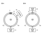
- 3A and 3B are diagrams illustrating the operation of the rotary coupler according to the first embodiment, in which the coupling portion of the rotary part is not opposed to the lossy medium of the fixed part, and the coupling portion of the rotary part is opposed to the lossy medium of the fixed part.
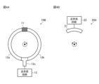
- 4A and 4B are diagrams showing the configurations of a fixed section and a rotating section in a rotary coupler according to embodiment 2.
- FIG. 4A is a schematic diagram showing the configuration of the fixed section
- Fig. 4B is a schematic diagram showing the configuration of the rotating section.
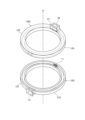
- FIG. 11 is an exploded perspective view of a rotary coupler according to a third embodiment.
- 6A and 6B are diagrams illustrating a configuration of a rotary coupler according to a third embodiment, in which Fig. 6A is a plan view of the rotary coupler, and Fig. 6B is a cross-sectional view taken along the line VI-VI in Fig. 6A.
- Embodiment 1 A rotary coupler according to a first embodiment will be described with reference to FIGS. 1 to 3.
- FIG. 1 A rotary coupler according to a first embodiment will be described with reference to FIGS. 1 to 3.
- FIG. 1 A rotary coupler according to a first embodiment will be described with reference to FIGS. 1 to 3.
- FIG. 1 A rotary coupler according to a first embodiment will be described with reference to FIGS. 1 to 3.
- Fig. 1 is a schematic diagram of the rotary coupler according to the first embodiment.
- Fig. 2 is a diagram showing the configuration of the fixed part 10A and the rotating part 20A according to the first embodiment.
- the rotary coupler As shown in FIG. 1, the rotary coupler according to the first embodiment includes a fixed portion 10A and a rotating portion 20A. This rotary coupler transmits and receives signals (e.g., high-frequency signals) between the fixed portion 10A and the rotating portion 20A using electromagnetic coupling.
- signals e.g., high-frequency signals
- the fixed part 10A and the rotating part 20A are arranged coaxially and are separated from each other with a certain gap in the axial direction.
- the rotating part 20A rotates around the central axis O (see FIG. 2) of the rotary coupler relative to the fixed part 10A.
- the arrow surrounding the central axis O indicates the rotation direction of the rotating part 20A.
- the rotating part 20A can rotate both clockwise and counterclockwise.
- the fixed part 10A has a lossy medium 11, a first waveguide 12a (hereinafter simply referred to as waveguide 12a), a second waveguide 12b (hereinafter simply referred to as waveguide 12b), and a transmission/reception circuit 13.
- the transmission/reception circuit 13 constitutes the fixed side transmission/reception circuit.
- Both the waveguides 12a and 12b are arc-shaped and have the same diameter. Furthermore, the waveguides 12a and 12b are arranged on the same plane and are coaxial with the central axis O. Therefore, the waveguides 12a and 12b are arranged facing each other, and as a whole, they form a substantially circular arc shape.
- One end of the waveguide 12a and one end of the waveguide 12b are connected via a lossy medium 11. Meanwhile, the other end of the waveguide 12a and the other end of the waveguide 12b are each connected to a transmitting/receiving circuit 13.
- the rotating part 20A has a coupling part 21 and a transmitting/receiving circuit 22.
- the transmitting/receiving circuit 22 constitutes the rotating side transmitting/receiving circuit.
- the coupling portion 21 is a transmission line.
- the coupling portion 21 is arc-shaped and has the same diameter as the diameter D of the waveguides 12a and 12b.
- the length of the coupling portion 21 is different from the lengths of the waveguides 12a and 12b. Specifically, the length of the coupling portion 21 is shorter than the lengths of the waveguides 12a and 12b.
- the coupling portion 21 is also arranged coaxially with the central axis O. That is, the waveguides 12a and 12b, and the coupling portion 21 are arranged coaxially. Furthermore, the coupling portion 21 is connected to the transmission/reception circuit 22.
- the coupling portion 21 rotates together with the rotation of the rotating portion 20A around the central axis O. At this time, the coupling portion 21 faces at least one of the waveguides 12a and 12b in the axial direction. Therefore, the coupling portion 21 is electrically coupled to at least one of the waveguides 12a and 12b. As a result, signals are transmitted and received between the transmission/reception circuit 13 of the fixed portion 10A and the transmission/reception circuit 22 of the rotating portion 20A.
- FIG. 3 is a diagram showing the operation of the rotary coupler according to the first embodiment. Note that the white arrows shown in FIG. 1 and FIG. 3 indicate the flow of signals.
- Figure 3A is a diagram showing a state in which the coupling part 21 of the rotating part 20A does not face the lossy medium 11 of the fixed part 10A.
- the signal output from the transmission/reception circuit 13 of the fixed part 10A is in phase with the other end of the waveguide 12a and the other end of the waveguide 12b and is split into two.
- the signal distributed to the other end of waveguide 12a is transmitted along the length of waveguide 12a and then absorbed by lossy medium 11.
- the signal distributed to the other end of waveguide 12b is transmitted along the length of waveguide 12b and then reaches coupling section 21. Therefore, the signal that reaches coupling section 21 is electromagnetically coupled with coupling section 21 and transmitted to transmission/reception circuit 22.
- Such a signal that travels from transmission/reception circuit 13, through waveguide 12b, through coupling section 21, and to transmission/reception circuit 22 is transmitted without discontinuity in the electromagnetic field distribution and as a wideband signal.
- Figure 3B is a diagram showing the state in which the coupling part 21 of the rotating part 20A faces the lossy medium 11 of the fixed part 10A.
- the signal output from the transmission/reception circuit 13 of the fixed part 10A is in phase with the other end of the waveguide 12a and the other end of the waveguide 12b and is split into two.
- the signal distributed to the other end of the waveguide 12a is transmitted along the length of the waveguide 12a before reaching the coupling section 21.
- the signal distributed to the other end of the waveguide 12b is transmitted along the length of the waveguide 12b before reaching the coupling section 21.
- the signal transmitted from waveguide 12a and the signal transmitted from waveguide 12b are combined in phase because waveguides 12a and 12b are electromagnetically coupled to coupling section 21.
- the combined signal is then transmitted to transmission/reception circuit 22.
- Such a signal that travels from transmission/reception circuit 13, through waveguides 12a and 12b, through coupling section 21, and to transmission/reception circuit 22 is transmitted as a wideband signal without discontinuity in the electromagnetic field distribution.
- the rotary coupler according to embodiment 1 does not cause discontinuity in the electromagnetic field distribution when the coupling unit 21 is placed at a rotational angle position other than directly above the lossy medium 11. Furthermore, when the rotary coupler according to embodiment 1 is placed at a rotational angle position corresponding to directly above the lossy medium 11, the signals from both are combined in phase by electromagnetic coupling between the waveguides 12a, 12b and the coupling unit 21. Therefore, the rotary coupler according to embodiment 1 can transmit and receive signals between the fixed unit 10A and the rotating unit 20A regardless of the rotational angle position of the rotating unit 20A.
- the rotary coupler is a rotary coupler that uses electromagnetic coupling to transmit and receive signals between the fixed part 10A and the rotating part 20A that is rotatably supported by the fixed part 10A.
- the fixed part 10A has waveguides 12a and 12b that have the same diameter, are arc-shaped, and are arranged facing each other with the central axis O as the center, a lossy medium 11 to which one end of the waveguide 12a and one end of the waveguide 12b are connected, and a transmission/reception circuit 13 to which the other end of the waveguide 12a and the other end of the waveguide 12b are connected.
- the rotating part 20A rotates around the central axis O as the center of rotation, and has a coupling part 21 that electromagnetically couples with at least one of the waveguides 12a and 12b, and a transmission/reception circuit 22 that is connected to the coupling part 21 and transmits and receives signals between the transmission/reception circuit 13. Therefore, the rotary coupler according to embodiment 1 can transmit and receive signals between the fixed part 10A and the rotating part 20A at all rotation angle positions of the rotating part 20A.
- FIG. 4 is a diagram showing the configuration of a fixed section 10B and a rotating section 20A in the rotary coupler according to the second embodiment. Note that components having the same functions as those described in the first embodiment are given the same reference numerals, and the description thereof will be omitted.
- the rotary coupler according to the second embodiment includes a fixed portion 10B and a rotating portion 20A.
- This rotary coupler transmits and receives signals between the fixed portion 10B and the rotating portion 20A using electromagnetic coupling.
- the rotary coupler according to the second embodiment has a structure including a fixed portion 10B instead of the fixed portion 10A of the rotary coupler according to the first embodiment.
- the fixed part 10B has a lossy medium 11, a waveguide 12a, a waveguide 12b, a branch part 12c, and a transmitting/receiving circuit 13.
- the waveguide 12a, the waveguide 12b, and the branch portion 12c are assumed to be microstrip lines, and the lossy medium 11 is assumed to be a terminator. Therefore, the rotary coupler can easily manufacture the waveguide 12a, the waveguide 12b, and the branch portion 12c. Furthermore, by using the lossy medium 11 as a terminator, the rotary coupler can prevent unwanted reflection of signals at the ends of the microstrip lines (the tips of the waveguide 12a and the waveguide 12b).
- the branch portion 12c is formed in a T-shape or a bifurcated shape.
- the base end of the branch portion 12c is connected to the transmission/reception circuit 13.
- the two ends of the branch portion 12c are connected to the other end of the waveguide 12a and the other end of the waveguide 12b, respectively.
- the rotating section 20A has a coupling section 21 and a transmitting/receiving circuit 22.
- the coupling section 21 is assumed to be a probe using a microstrip line.
- the position of the probe is disposed on the rotation radius (diameter dimension D) of the lossy medium 11, the waveguide 12a, the waveguide 12b, and the branch section 12c.
- the rotary coupler is capable of adjusting the position of the probe as appropriate, so long as it is within a range in which the desired amount of electromagnetic coupling can be obtained.
- the transmission line used in the probe may be in a form other than a microstrip line. It is also preferable that the transmission line used in the probe does not resonate at the frequency used. For example, if the transmission line is linear, the length of the transmission line may be set to be equal to ⁇ /2.
- the rotary coupler according to embodiment 2 does not cause discontinuity in the electromagnetic field distribution when the coupling unit 21 is placed at a rotational angle position other than directly above the lossy medium 11. Furthermore, when the rotary coupler according to embodiment 2 is placed at a rotational angle position corresponding to directly above the lossy medium 11, the signals from both are combined in phase by electromagnetic coupling between the waveguides 12a, 12b and the coupling unit 21. Therefore, the rotary coupler according to embodiment 2 can transmit and receive signals between the fixed unit 10B and the rotating unit 20A regardless of the rotational angle position of the rotating unit 20A.
- the rotary coupler according to the second embodiment is a rotary coupler that uses electromagnetic coupling to transmit and receive signals between the fixed part 10B and the rotating part 20A that is rotatably supported by the fixed part 10B.
- the fixed part 10B has waveguides 12a and 12b that have the same diameter, are arc-shaped, and are arranged facing each other with the central axis O as the center, a lossy medium 11 to which one end of the waveguide 12a and one end of the waveguide 12b are connected, and a transmission/reception circuit 13 to which the other end of the waveguide 12a and the other end of the waveguide 12b are connected.
- the rotating part 20A rotates around the central axis O as the center of rotation, and has a coupling part 21 that electromagnetically couples with at least one of the waveguides 12a and 12b, and a transmission/reception circuit 22 that is connected to the coupling part 21 and transmits and receives signals between the transmission/reception circuit 13. Therefore, the rotary coupler according to embodiment 2 can transmit and receive signals between the fixed part 10B and the rotating part 20A at all rotation angle positions of the rotating part 20A.
- FIG. 5 is an exploded perspective view of the rotary coupler according to the third embodiment.
- Fig. 6 is a diagram showing the configuration of the rotary coupler according to the third embodiment. Note that components having the same functions as those described in the first embodiment above are given the same reference numerals, and the description thereof will be omitted.
- the rotary coupler includes a fixed portion 10C and a rotating portion 20C.
- This rotary coupler transmits and receives signals between the fixed portion 10C and the rotating portion 20C using electromagnetic coupling.
- the fixed section 10C has a lossy medium 11, a first fixed-side half-waveguide 121 of the waveguide 12a (hereinafter simply referred to as the fixed-side half-waveguide 121), a second fixed-side half-waveguide 123 of the waveguide 12b (hereinafter simply referred to as the fixed-side half-waveguide 123), and a transmitting/receiving circuit 13.
- the fixed section 10C assumes that the lossy medium 11 is a radio wave absorber.
- the rotating section 20C has a coupling section 21, a transmitting/receiving circuit 22, a first rotating-side half-waveguide 122 of the waveguide 12a (hereinafter simply referred to as the rotating-side half-waveguide 122), and a second rotating-side half-waveguide 124 of the waveguide 12b (hereinafter simply referred to as the rotating-side half-waveguide 124).
- the waveguide 12a has a half structure (or a divided structure) in the axial direction, with the boundary between the fixed part 10C and the rotating part 20C.
- This waveguide 12a is divided into a fixed-side half waveguide 121 and a rotating-side half waveguide 122.
- the fixed-side half waveguide 121 and the rotating-side half waveguide 122 are both groove-shaped, and are arranged so that their openings face each other in the axial direction. Therefore, a hollow section that serves as a waveguide is formed between them.
- the waveguide 12b has a half structure (or a divided structure) in the axial direction, with the boundary between the fixed part 10C and the rotating part 20C.
- This waveguide 12b is divided into a fixed-side half waveguide 123 and a rotating-side half waveguide 124.
- the fixed-side half waveguide 123 and the rotating-side half waveguide 124 are both groove-shaped, and are arranged so that their openings face each other in the axial direction. Therefore, a hollow section that serves as a waveguide is formed between them.
- One end of the fixed-side half-split waveguide 121 and one end of the fixed-side half-split waveguide 123 are connected via a lossy medium 11.
- the other end of the fixed-side half-split waveguide 121 and the other end of the fixed-side half-split waveguide 123 are each connected to the transmission/reception circuit 13.
- the other end of the fixed-side half-split waveguide 121 and the other end of the fixed-side half-split waveguide 123 may also be connected to the transmission/reception circuit 13 via a branch portion 12c.
- one end of the rotating side half-split waveguide 122 and one end of the rotating side half-split waveguide 124 are connected via a coupling portion 21.
- the other end of the fixed side half-split waveguide 121 and the other end of the fixed side half-split waveguide 123 are connected to each other.
- the rotary coupler according to embodiment 3 does not cause discontinuity in the electromagnetic field distribution when the coupling unit 21 is placed at a rotational angle position other than directly above the lossy medium 11. Furthermore, when the rotary coupler according to embodiment 3 is placed at a rotational angle position corresponding to directly above the lossy medium 11, the signals from both are combined in phase by electromagnetic coupling between the waveguides 12a, 12b and the coupling unit 21. Therefore, the rotary coupler according to embodiment 3 can transmit and receive signals between the fixed unit 10C and the rotating unit 20C regardless of the rotational angle position of the rotating unit 20C.
- the fixed part 10C includes a fixed-side half-slit waveguide 121 that constitutes the waveguide 12a, a fixed-side half-slit waveguide 123 that constitutes the waveguide 12b, a lossy medium 11 to which one end of the fixed-side half-slit waveguide 121 and one end of the fixed-side half-slit waveguide 123 are connected, and a transmission/reception circuit 13 to which the other end of the fixed-side half-slit waveguide 121 and the other end of the fixed-side half-slit waveguide 123 are connected.
- the rotating unit 20C has a rotating half-waveguide 122 constituting the waveguide 12a, a rotating half-waveguide 124 constituting the waveguide 12b, a coupling unit 21 to which one end of the rotating half-waveguide 122 and one end of the rotating half-waveguide 124 are connected and which rotates about the central axis O as the center of rotation and which electromagnetically couples with at least one of the fixed half-waveguide 121 and the fixed half-waveguide 123, and a transmission/reception circuit 22 connected to the coupling unit 21 and which transmits and receives signals with the transmission/reception circuit 13. Therefore, the rotary coupler according to the third embodiment can transmit and receive signals between the fixed unit 10C and the rotating unit 20C at all rotation angle positions of the rotating unit 20C.
Landscapes
- Waveguide Connection Structure (AREA)
Abstract
Description
本開示は、回転結合器に関する。 This disclosure relates to a rotary coupler.
従来、固定部及びこの固定部に対して回転する回転部を備える回転結合器が、提供されている。この回転結合器は、固定部と回転部との間において、信号を送受信可能とするものである。このような、従来の回転結合器としては、例えば、特許文献1に開示されている。 Conventionally, a rotary coupler has been provided that includes a fixed part and a rotating part that rotates relative to the fixed part. This rotary coupler allows signals to be transmitted and received between the fixed part and the rotating part. An example of such a conventional rotary coupler is disclosed in Patent Document 1.
特許文献1に開示された回転結合器は、マイクロストリップ線路を、固定部と回転部とにそれぞれ備えている。固定部に設けられたマイクロストリップ線路と、回転部に設けられたマイクロストリップ線路とは、互いに異なる長さで、且つ、円弧状に形成されており、互いに対向して配置されている。特許文献1に開示された回転結合器は、固定部に対して、回転部を回転させながら、固定部のマイクロストリップ線路と回転部のマイクロストリップ線路との間を電磁結合することにより、2つのマイクロストリップ線路間において、信号の送受信を可能としている。 The rotary coupler disclosed in Patent Document 1 has microstrip lines in both the fixed section and the rotating section. The microstrip lines provided in the fixed section and the microstrip lines provided in the rotating section are of different lengths, are formed in an arc shape, and are arranged opposite each other. The rotary coupler disclosed in Patent Document 1 enables signals to be transmitted and received between the two microstrip lines by electromagnetically coupling the microstrip lines of the fixed section and the microstrip lines of the rotating section while rotating the rotating section relative to the fixed section.
ここで、回転部のマイクロストリップ線路が、固定部のマイクロストリップ線路に設けられる終端部と対向する位置を、通過(回転)する場合、当該回転部のマイクロストリップ線路に対応する固定部のマイクロストリップ線路が、一時的に無くなる。このため、2つのマイクロストリップ線路間における電磁的な結合力が、非常に小さくなり、利得が低下してしまう。この結果、特許文献1に開示された回転結合器は、回転部の全ての回転角度において、信号の送受信ができないおそれがある。 Here, when the microstrip line of the rotating part passes (rotates) a position facing the terminal end of the microstrip line of the fixed part, the microstrip line of the fixed part corresponding to the microstrip line of the rotating part temporarily disappears. This causes the electromagnetic coupling force between the two microstrip lines to become very small, resulting in a decrease in gain. As a result, the rotary coupler disclosed in Patent Document 1 may not be able to transmit and receive signals at all rotation angles of the rotating part.
本開示は、上記のような課題を解決するためになされたもので、回転部の全ての回転角度位置において、固定部と回転部との間で信号の送受信を行うことができる回転結合器を提供することを目的とする。 The present disclosure has been made to solve the problems described above, and aims to provide a rotary coupler that can transmit and receive signals between a fixed part and a rotating part at all rotation angle positions of the rotating part.
本開示に係る回転結合器は、固定部と、当該固定部に対して回転可能に支持される回転部との間において、信号の送受信を、電磁的な結合を用いて行う回転結合器であって、固定部は、同一径を有し、且つ、円弧状をなして、向き合うように中心軸を中心として配置される第1の導波管及び第2の導波管と、第1の導波管の一端と第2の導波管の一端とが接続される損失性媒質と、第1の導波管の他端と第2の導波管の他端とが接続される固定側送受信回路とを有し、回転部は、中心軸を回転中心として回転し、第1の導波管及び第2の導波管のうちの少なくともいずれか一方の導波管との間で、電磁結合する結合部と、結合部と接続し、固定側送受信回路との間で信号の送受信を行う回転側送受信回路とを有するものである。 The rotary coupler according to the present disclosure is a rotary coupler that uses electromagnetic coupling to transmit and receive signals between a fixed part and a rotating part that is rotatably supported on the fixed part, the fixed part having a first waveguide and a second waveguide that have the same diameter and are arranged in an arc shape and facing each other about a central axis, a lossy medium to which one end of the first waveguide and one end of the second waveguide are connected, and a fixed-side transmission/reception circuit to which the other end of the first waveguide and the other end of the second waveguide are connected, the rotating part rotates about the central axis as the center of rotation and has a coupling part that electromagnetically couples with at least one of the first waveguide and the second waveguide, and a rotating-side transmission/reception circuit that is connected to the coupling part and transmits and receives signals between the fixed-side transmission/reception circuit.
本開示によれば、回転部の全ての回転角度位置において、固定部と回転部との間で信号の送受信を行うことができる。 According to the present disclosure, signals can be transmitted and received between the fixed part and the rotating part at all rotation angle positions of the rotating part.
以下、本開示をより詳細に説明するために、本開示を実施するための形態について、添付の図面に従って説明する。 Below, in order to explain this disclosure in more detail, the form for implementing this disclosure will be described with reference to the attached drawings.
実施の形態1.
実施の形態1に係る回転結合器について、図1から図3を用いて説明する。
Embodiment 1.
A rotary coupler according to a first embodiment will be described with reference to FIGS. 1 to 3. FIG.
先ず、実施の形態1に係る回転結合器の構成について、図1及び図2を用いて説明する。図1は、実施の形態1に係る回転結合器の概略構成図である。図2は、実施の形態1に係る固定部10A及び回転部20Aの構成を示す図である。
First, the configuration of the rotary coupler according to the first embodiment will be described with reference to Figs. 1 and 2. Fig. 1 is a schematic diagram of the rotary coupler according to the first embodiment. Fig. 2 is a diagram showing the configuration of the
図1に示すように、実施の形態1に係る回転結合器は、固定部10A及び回転部20Aを備えている。この回転結合器は、固定部10Aと回転部20Aとの間における信号(例えば、高周波信号)の送受信を、電磁的な結合を用いて行うものである。
As shown in FIG. 1, the rotary coupler according to the first embodiment includes a fixed
固定部10Aと回転部20Aとは、同軸上に配置されており、その軸方向において所定の隙間量を有して、互いに離間している。回転部20Aは、固定された固定部10Aに対して、回転結合器の中心軸O(図2参照)を回転中心として回転する。なお、図2Bにおいて、中心軸Oを囲う矢印は、回転部20Aの回転方向を示している。即ち、回転部20Aは、時計回り及び反時計回りで回転可能となっている。
The
図1及び図2に示すように、固定部10Aは、損失性媒質11、第1の導波管12a(以下、単に、導波管12aと記載する)、第2の導波管12b(以下、単に、導波管12bと記載する)、及び、送受信回路13を有している。なお、送受信回路13は、固定側送受信回路を構成するものである。
As shown in Figures 1 and 2, the
導波管12aと導波管12bとは、共に円弧状をなしており、同一径を有している。また、導波管12aと導波管12bとは、互いに中心軸Oと同軸上に配置された状態で、同一平面上に設けられている。このため、導波管12aと導波管12bとは、互いに向き合うように配置されており、全体としても、実質的に1周する円弧状をなしている。
Both the
導波管12aの一端と、導波管12bの一端とは、損失性媒質11を介して、接続されている。一方、導波管12aの他端と、導波管12bの他端とは、送受信回路13にそれぞれ接続されている。
One end of the
図1及び図2に示すように、回転部20Aは、結合部21及び送受信回路22を有している。なお、送受信回路22は、回転側送受信回路を構成するものである。
As shown in Figures 1 and 2, the
結合部21は、伝送線路である。この結合部21は、円弧状をなしており、導波管12a,12bの径寸法Dと同じ径寸法を有している。結合部21の長さは、導波管12a,12bの長さとは、異なる長さとなっている。具体的には、結合部21の長さは、導波管12a,12bの長さよりも短い長さとなっている。また、結合部21は、中心軸Oと同軸上に配置されている。即ち、導波管12a、導波管12b、及び、結合部21は、同軸上に配置されている。更に、結合部21は、送受信回路22と接続されている。
The
結合部21は、回転部20Aの中心軸O周りの回転と共に回転する。このとき、結合部21は、導波管12a,12bのうちの少なくともいずれか一方の導波管と、軸方向において対向する。このため、結合部21は、導波管12a,12bのうちの少なくともいずれか一方の導波管と、電気結合する。この結果、固定部10Aの送受信回路13と、回転部20Aの送受信回路22との間において、信号の送受信が行われる。
The
次に、実施の形態1に係る回転結合器の動作について、図3を用いて説明する。図3は、実施の形態1に係る回転結合器の動作を示す図である。なお、図1及び図3に示す白抜きの矢印は、信号の流れを示している。 Next, the operation of the rotary coupler according to the first embodiment will be explained with reference to FIG. 3. FIG. 3 is a diagram showing the operation of the rotary coupler according to the first embodiment. Note that the white arrows shown in FIG. 1 and FIG. 3 indicate the flow of signals.
図3Aは、回転部20Aの結合部21が固定部10Aの損失性媒質11と対向していない状態を示す図である。この図3Aに示すように、回転部20Aの結合部21が固定部10Aの損失性媒質11と対向していない場合(言い換えれば、結合部21が損失性媒質11に対してずれて配置される)、固定部10Aの送受信回路13から出力された信号は、導波管12aの他端及び導波管12bの他端に対して、同相で、且つ、2分配される。
Figure 3A is a diagram showing a state in which the
導波管12aの他端に分配された信号は、当該導波管12aの長さ方向に沿って伝送された後、損失性媒質11に吸収される。一方、導波管12bの他端に分配された信号は、当該導波管12bの長さ方向に沿って伝送された後、結合部21に到達する。このため、結合部21に到達した信号は、当該結合部21と電磁結合し、送受信回路22に伝送される。このような、送受信回路13から、導波管12bを介して、結合部21を通過し、送受信回路22に至るまでの信号は、電磁界分布に不連続性が無く、且つ、広帯域な信号として、伝送される。
The signal distributed to the other end of
図3Bは、回転部20Aの結合部21が固定部10Aの損失性媒質11と対向した状態を示す図である。この図3Bに示すように、回転部20Aの結合部21が固定部10Aの損失性媒質11と対向する場合(言い換えれば、結合部21が損失性媒質11の直上に位置する場合)、固定部10Aの送受信回路13から出力された信号は、導波管12aの他端及び導波管12bの他端に対して、同相で、且つ、2分配される。
Figure 3B is a diagram showing the state in which the
導波管12aの他端に分配された信号は、当該導波管12aの長さ方向に沿って伝送された後、結合部21に到達する。一方、導波管12bの他端に分配された信号は、当該導波管12bの長さ方向に沿って伝送された後、結合部21に到達する。
The signal distributed to the other end of the
ここで、導波管12aの長さと、導波管12bの長さとが、同じ長さである場合、又は、導波管12aの長さと導波管12bの長さとの差が、信号の波長の整数倍である場合、導波管12aから伝送されてきた信号と、導波管12bから伝送されてきた信号とは、導波管12a及び導波管12bと結合部21とが電磁結合するため、同相で合成される。そして、合成された信号は、送受信回路22に伝送される。このような、送受信回路13から、導波管12a及び導波管12bを介して、結合部21を通過し、送受信回路22に至るまでの信号は、電磁界分布に不連続性が無く、且つ、広帯域な信号として、伝送される。
Here, when the length of
なお、上述した回転結合器の動作においては、固定部10Aの送受信回路13から送信された信号を、回転部20Aの送受信回路22で受信する動作を説明したが、この説明から、回転部20Aの送受信回路22から送信された信号を、固定部10Aの送受信回路13で受信する動作を十分に理解することができるので、その説明については省略する。
In addition, in the operation of the rotary coupler described above, the operation of receiving a signal transmitted from the transmission/
従って、実施の形態1に係る回転結合器は、結合部21が損失性媒質11の直上以外に対応する回転角度位置に配置される場合、電磁界分布に不連続性を発生させることが無い。また、実施の形態1に係る回転結合器は、結合部21が損失性媒質11の直上に対応する回転角度位置に配置される場合、導波管12a,12bと結合部21との電磁結合によって、双方からの信号を同相で合成する。このため、実施の形態1に係る回転結合器は、回転部20Aがどのような回転角度位置であっても、固定部10Aと回転部20Aとの間で信号の送受信を行うことができる。
Therefore, the rotary coupler according to embodiment 1 does not cause discontinuity in the electromagnetic field distribution when the
以上、実施の形態1に係る回転結合器は、固定部10Aと、当該固定部10Aに対して回転可能に支持される回転部20Aとの間において、信号の送受信を、電磁的な結合を用いて行う回転結合器である。固定部10Aは、同一径を有し、且つ、円弧状をなして、向き合うように中心軸Oを中心として配置される導波管12a,12bと、導波管12aの一端と導波管12bの一端とが接続される損失性媒質11と、導波管12aの他端と導波管12bの他端とが接続される送受信回路13とを有する。回転部20Aは、中心軸Oを回転中心として回転し、導波管12a,12bのうちの少なくともいずれか一方の導波管との間で、電磁結合する結合部21と、結合部21と接続し、送受信回路13との間で信号の送受信を行う送受信回路22とを有する。このため、実施の形態1に係る回転結合器は、回転部20Aの全ての回転角度位置において、固定部10Aと回転部20Aとの間で信号の送受信を行うことができる。
As described above, the rotary coupler according to the first embodiment is a rotary coupler that uses electromagnetic coupling to transmit and receive signals between the
実施の形態2.
実施の形態2に係る回転結合器について、図4を用いて説明する。図4は、実施の形態2に係る回転結合器における固定部10B及び回転部20Aの構成を示す図である。なお、上述した実施の形態1で説明した構成と同様の機能を有する構成については、同一の符号を付し、その説明を省略する。
Embodiment 2.
A rotary coupler according to the second embodiment will be described with reference to Fig. 4. Fig. 4 is a diagram showing the configuration of a fixed
図4に示すように、実施の形態2に係る回転結合器は、固定部10B及び回転部20Aを備えている。この回転結合器は、固定部10Bと回転部20Aとの間における信号の送受信を、電磁的な結合を用いて行うものである。即ち、実施の形態2に係る回転結合器は、実施の形態1に係る回転結合器の固定部10Aに替えて、固定部10Bを備えた構造となっている。
As shown in FIG. 4, the rotary coupler according to the second embodiment includes a fixed
図4Aに示すように、固定部10Bは、損失性媒質11、導波管12a、導波管12b、分岐部12c、及び、送受信回路13を有している。
As shown in FIG. 4A, the
固定部10Bは、導波管12a、導波管12b、及び、分岐部12cを、マイクロストリップ線路と想定しており、損失性媒質11を終端器と想定している。このため、回転結合器は、導波管12a、導波管12b、及び、分岐部12cを、容易に製造することができる。また、回転結合器は、損失性媒質11を終端器とすることで、マイクロストリップ線路の末端(導波管12aの先端、及び、導波管12bの先端)における、信号の不要な反射を防ぐことができる。
In the fixed
分岐部12cは、T字状又は二股状に形成されている。分岐部12cの基端は、送受信回路13と接続されている。また、分岐部12cの2つの先端は、導波管12aの他端及び導波管12bの他端に、それぞれ接続されている。
The
図4Bに示すように、回転部20Aは、結合部21及び送受信回路22を有している。実施の形態2に係る回転結合器は、結合部21を、マイクロストリップ線路を用いたプローブと想定している。この場合、プローブの位置は、損失性媒質11、導波管12a、導波管12b、及び、分岐部12cの回転半径(径寸法D)上に配置されている。このとき、回転結合器は、所望の電磁結合量が得られる範囲内であれば、プローブの位置を、適宜、調整可能となっている。
As shown in FIG. 4B, the
なお、プローブに用いられる伝送線路は、マイクロストリップ線路以外の線路形態でも良い。また、プローブに用いられる伝送線路は、使用周波数において共振しないことが好ましい。例えば、その伝送線路の形状が線状であるならば、当該伝送線路は、λ/2に等しい長さにすれば良い。 The transmission line used in the probe may be in a form other than a microstrip line. It is also preferable that the transmission line used in the probe does not resonate at the frequency used. For example, if the transmission line is linear, the length of the transmission line may be set to be equal to λ/2.
従って、実施の形態2に係る回転結合器は、結合部21が損失性媒質11の直上以外に対応する回転角度位置に配置される場合、電磁界分布に不連続性を発生させることが無い。また、実施の形態2に係る回転結合器は、結合部21が損失性媒質11の直上に対応する回転角度位置に配置される場合、導波管12a,12bと結合部21との電磁結合によって、双方からの信号を同相で合成する。このため、実施の形態2に係る回転結合器は、回転部20Aがどのような回転角度位置であっても、固定部10Bと回転部20Aとの間で信号の送受信を行うことができる。
Therefore, the rotary coupler according to embodiment 2 does not cause discontinuity in the electromagnetic field distribution when the
以上、実施の形態2に係る回転結合器は、固定部10Bと、当該固定部10Bに対して回転可能に支持される回転部20Aとの間において、信号の送受信を、電磁的な結合を用いて行う回転結合器である。固定部10Bは、同一径を有し、且つ、円弧状をなして、向き合うように中心軸Oを中心として配置される導波管12a,12bと、導波管12aの一端と導波管12bの一端とが接続される損失性媒質11と、導波管12aの他端と導波管12bの他端とが接続される送受信回路13とを有する。回転部20Aは、中心軸Oを回転中心として回転し、導波管12a,12bのうちの少なくともいずれか一方の導波管との間で、電磁結合する結合部21と、結合部21と接続し、送受信回路13との間で信号の送受信を行う送受信回路22とを有する。このため、実施の形態2に係る回転結合器は、回転部20Aの全ての回転角度位置において、固定部10Bと回転部20Aとの間で信号の送受信を行うことができる。
As described above, the rotary coupler according to the second embodiment is a rotary coupler that uses electromagnetic coupling to transmit and receive signals between the
実施の形態3.
実施の形態3に係る回転結合器について、図5及び図6を用いて説明する。図5は、実施の形態3に係る回転結合器の分解斜視図である。図6は、実施の形態3に係る回転結合器の構成を示す図である。なお、上述した実施の形態1で説明した構成と同様の機能を有する構成については、同一の符号を付し、その説明を省略する。
Embodiment 3.
A rotary coupler according to the third embodiment will be described with reference to Fig. 5 and Fig. 6. Fig. 5 is an exploded perspective view of the rotary coupler according to the third embodiment. Fig. 6 is a diagram showing the configuration of the rotary coupler according to the third embodiment. Note that components having the same functions as those described in the first embodiment above are given the same reference numerals, and the description thereof will be omitted.
図5及び図6に示すように、実施の形態3に係る回転結合器は、固定部10C及び回転部20Cを備えている。この回転結合器は、固定部10Cと回転部20Cとの間における信号の送受信を、電磁的な結合を用いて行うものである。
As shown in Figures 5 and 6, the rotary coupler according to the third embodiment includes a fixed portion 10C and a
固定部10Cは、損失性媒質11、導波管12aの第1の固定側半割導波管121(以下、単に、固定側半割導波管121と記載する)、導波管12bの第2の固定側半割導波管123(以下、単に、固定側半割導波管123と記載する)、及び、送受信回路13を有している。固定部10Cは、損失性媒質11を電波吸収体と想定している。
The fixed section 10C has a
これに対して、回転部20Cは、結合部21、送受信回路22、導波管12aの第1の回転側半割導波管122(以下、単に、回転側半割導波管122と記載する)、及び、導波管12bの第2の回転側半割導波管124(以下、単に、回転側半割導波管124と記載する)を有している。
In contrast, the
即ち、導波管12aは、軸方向において、固定部10Cと回転部20Cとの間を境にして、半割構造(又は分割構造)をなしている。この導波管12aは、固定側半割導波管121と回転側半割導波管122とに分割されて構成されている。固定側半割導波管121及び回転側半割導波管122は、共に溝型をなしており、開口部同士を軸方向において対向させるように配置されている。このため、それらの間には、導波路となる中空部が形成される。
In other words, the
一方、導波管12bは、軸方向において、固定部10Cと回転部20Cとの間を境にして、半割構造(又は分割構造)をなしている。この導波管12bは、固定側半割導波管123と回転側半割導波管124とに分割されて構成されている。固定側半割導波管123及び回転側半割導波管124は、共に溝型をなしており、開口部同士を軸方向において対向させるように配置されている。このため、それらの間には、導波路となる中空部が形成される。
On the other hand, the
固定側半割導波管121の一端と、固定側半割導波管123の一端とは、損失性媒質11を介して、接続されている。固定側半割導波管121の他端と、固定側半割導波管123の他端とは、送受信回路13にそれぞれ接続されている。なお、固定側半割導波管121の他端と、固定側半割導波管123の他端とは、分岐部12cを介して、送受信回路13に接続されても良い。
One end of the fixed-side half-
また、回転側半割導波管122の一端と、回転側半割導波管124の一端とは、結合部21を介して、接続されている。固定側半割導波管121の他端と、固定側半割導波管123の他端とは、互いに接続されている。
Furthermore, one end of the rotating side half-
従って、実施の形態3に係る回転結合器は、結合部21が損失性媒質11の直上以外に対応する回転角度位置に配置される場合、電磁界分布に不連続性を発生させることが無い。また、実施の形態3に係る回転結合器は、結合部21が損失性媒質11の直上に対応する回転角度位置に配置される場合、導波管12a,12bと結合部21との電磁結合によって、双方からの信号を同相で合成する。このため、実施の形態3に係る回転結合器は、回転部20Cがどのような回転角度位置であっても、固定部10Cと回転部20Cとの間で信号の送受信を行うことができる。
Therefore, the rotary coupler according to embodiment 3 does not cause discontinuity in the electromagnetic field distribution when the
以上、実施の形態3に係る回転結合器は、固定部10Cと、当該固定部10Cに対して回転可能に支持される回転部20Cとの間において、信号の送受信を、電磁的な結合を用いて行う回転結合器であって、固定部10Cと回転部20Cとの間において、同一径を有し、且つ、円弧状をなして、向き合うように中心軸Oを中心として配置される、半割構造をなす導波管12a,12を備える。固定部10Cは、導波管12aを構成する固定側半割導波管121と、導波管12bを構成する固定側半割導波管123と、固定側半割導波管121の一端と固定側半割導波管123の一端とが接続される損失性媒質11と、固定側半割導波管121の他端と固定側半割導波管123の他端とが接続される送受信回路13とを有する。回転部20Cは、導波管12aを構成する回転側半割導波管122と、導波管12bを構成する回転側半割導波管124と、回転側半割導波管122の一端と回転側半割導波管124の一端とが接続されると共に、中心軸Oを回転中心として回転し、固定側半割導波管121及び固定側半割導波管123のうちの少なくともいずれか一方の導波管との間で、電磁結合する結合部21と、結合部21と接続し、送受信回路13との間で信号の送受信を行う送受信回路22とを有する。このため、実施の形態3に係る回転結合器は、回転部20Cの全ての回転角度位置において、固定部10Cと回転部20Cとの間で信号の送受信を行うことができる。
As described above, the rotary coupler according to the third embodiment is a rotary coupler that uses electromagnetic coupling to transmit and receive signals between a fixed part 10C and a
なお、本開示は、その開示の範囲内において、各実施の形態の自由な組み合わせ、或いは、各実施の形態における任意の構成要素の変形、若しくは、各実施の形態における任意の構成要素の省略が可能である。 Furthermore, within the scope of this disclosure, it is possible to freely combine the embodiments, modify any of the components in each embodiment, or omit any of the components in each embodiment.
本開示に係る回転結合器は、固定部に損失性媒質を設けることで、回転部の全ての回転角度位置において、固定部と回転部との間で信号の送受信を行うことができ、回転結合器等に用いるのに適している。 The rotary coupler according to the present disclosure is suitable for use in rotary couplers, etc., because it is possible to transmit and receive signals between the fixed and rotating parts at all rotation angle positions of the rotating part by providing a lossy medium in the fixed part.
10A,10B,10C 固定部、11 損失性媒質、12a 第1の導波管、121 第1の固定側半割導波管、122 第1の回転側半割導波管、12b 第2の導波管、123 第2の固定側半割導波管、124 第2の回転側半割導波管、12c 分岐部、13 送受信回路、20A,20C 回転部、21 結合部、22 送受信回路、D 径寸法、O 中心軸。 10A, 10B, 10C fixed section, 11 lossy medium, 12a first waveguide, 121 first fixed half waveguide, 122 first rotating half waveguide, 12b second waveguide, 123 second fixed half waveguide, 124 second rotating half waveguide, 12c branch section, 13 transmitting/receiving circuit, 20A, 20C rotating section, 21 coupling section, 22 transmitting/receiving circuit, D diameter, O central axis.
Claims (5)
前記固定部は、
同一径を有し、且つ、円弧状をなして、向き合うように中心軸を中心として配置される第1の導波管及び第2の導波管と、
前記第1の導波管の一端と前記第2の導波管の一端とが接続される損失性媒質と、
前記第1の導波管の他端と前記第2の導波管の他端とが接続される固定側送受信回路とを有し、
前記回転部は、
前記中心軸を回転中心として回転し、前記第1の導波管及び前記第2の導波管のうちの少なくともいずれか一方の導波管との間で、電磁結合する結合部と、
前記結合部と接続し、前記固定側送受信回路との間で信号の送受信を行う回転側送受信回路とを有する
ことを特徴とする回転結合器。 A rotary coupler that uses electromagnetic coupling to transmit and receive signals between a fixed part and a rotating part that is rotatably supported relative to the fixed part,
The fixing portion is
a first waveguide and a second waveguide having the same diameter, forming an arc shape, and disposed about a central axis so as to face each other;
a lossy medium to which one end of the first waveguide and one end of the second waveguide are connected;
a fixed-side transmitting/receiving circuit to which the other end of the first waveguide and the other end of the second waveguide are connected,
The rotating part is
a coupling portion that rotates about the central axis and is electromagnetically coupled with at least one of the first waveguide and the second waveguide;
a rotation-side transmitting/receiving circuit connected to the coupling portion and transmitting/receiving signals to/from the fixed-side transmitting/receiving circuit.
前記固定部と前記回転部との間において、同一径を有し、且つ、円弧状をなして、向き合うように中心軸を中心として配置される、半割構造をなす第1の導波管及び第2の導波管を備え、
前記固定部は、
前記第1の導波管を構成する第1の固定側半割導波管と、
前記第2の導波管を構成する第2の固定側半割導波管と、
前記第1の固定側半割導波管の一端と前記第2の固定側半割導波管の一端とが接続される損失性媒質と、
前記第1の固定側半割導波管の他端と前記第2の固定側半割導波管の他端とが接続される固定側送受信回路とを有し、
前記回転部は、
前記第1の導波管を構成する第1の回転側半割導波管と、
前記第2の導波管を構成する第2の回転側半割導波管と、
前記第1の回転側半割導波管の一端と前記第2の回転側半割導波管の一端とが接続されると共に、前記中心軸を回転中心として回転し、前記第1の固定側半割導波管及び前記第2の固定側半割導波管のうちの少なくともいずれか一方の導波管との間で、電磁結合する結合部と、
前記結合部と接続し、前記固定側送受信回路との間で信号の送受信を行う回転側送受信回路とを有する
ことを特徴とする回転結合器。 A rotary coupler that uses electromagnetic coupling to transmit and receive signals between a fixed part and a rotating part that is rotatably supported relative to the fixed part,
a first waveguide and a second waveguide having a split structure, the first waveguide and the second waveguide having the same diameter, being arc-shaped, and being disposed about a central axis so as to face each other, between the fixed portion and the rotating portion;
The fixing portion is
a first fixed half-waveguide constituting the first waveguide;
a second fixed half-waveguide constituting the second waveguide;
a lossy medium to which one end of the first fixed half-waveguide and one end of the second fixed half-waveguide are connected;
a fixed-side transmitting/receiving circuit to which the other end of the first fixed-side half-waveguide and the other end of the second fixed-side half-waveguide are connected,
The rotating part is
a first rotating half-waveguide constituting the first waveguide;
a second rotating half-waveguide constituting the second waveguide;
a coupling section that connects one end of the first rotating-side half-waveguide and one end of the second rotating-side half-waveguide, rotates about the central axis, and electromagnetically couples with at least one of the first fixed-side half-waveguide and the second fixed-side half-waveguide;
a rotation-side transmitting/receiving circuit connected to the coupling portion and transmitting/receiving signals to/from the fixed-side transmitting/receiving circuit.
ことを特徴とする請求項1又は請求項2記載の回転結合器。 3. The rotary coupler according to claim 1, wherein the first waveguide and the second waveguide have the same length.
ことを特徴とする請求項1又は請求項2記載の回転結合器。 3. A rotary coupler according to claim 1 or 2, wherein the difference between the length of said first waveguide and the length of said second waveguide is an integer multiple of a wavelength of a signal.
ことを特徴とする請求項1、請求項3、及び、請求項4のうちのいずれか1項記載の回転結合器。 5. The rotary coupler according to claim 1, 3, or 4, wherein the first waveguide and the second waveguide are microstrip lines.
Priority Applications (3)
| Application Number | Priority Date | Filing Date | Title |
|---|---|---|---|
| PCT/JP2023/022337 WO2024257320A1 (en) | 2023-06-16 | 2023-06-16 | Rotary coupler |
| JP2024575368A JP7651083B1 (en) | 2023-06-16 | 2023-06-16 | Rotary Coupler |
| TW112147865A TW202501875A (en) | 2023-06-16 | 2023-12-08 | Rotary coupler |
Applications Claiming Priority (1)
| Application Number | Priority Date | Filing Date | Title |
|---|---|---|---|
| PCT/JP2023/022337 WO2024257320A1 (en) | 2023-06-16 | 2023-06-16 | Rotary coupler |
Publications (1)
| Publication Number | Publication Date |
|---|---|
| WO2024257320A1 true WO2024257320A1 (en) | 2024-12-19 |
Family
ID=93851725
Family Applications (1)
| Application Number | Title | Priority Date | Filing Date |
|---|---|---|---|
| PCT/JP2023/022337 Ceased WO2024257320A1 (en) | 2023-06-16 | 2023-06-16 | Rotary coupler |
Country Status (3)
| Country | Link |
|---|---|
| JP (1) | JP7651083B1 (en) |
| TW (1) | TW202501875A (en) |
| WO (1) | WO2024257320A1 (en) |
Citations (3)
| Publication number | Priority date | Publication date | Assignee | Title |
|---|---|---|---|---|
| JPH0445505A (en) * | 1990-06-13 | 1992-02-14 | Sony Corp | Rotation coupler |
| JPH09500513A (en) * | 1994-04-17 | 1997-01-14 | ウルリヒ シュヴァーン | Data transmission equipment |
| US20200212528A1 (en) * | 2019-01-02 | 2020-07-02 | ThinKom Solutions, Inc | Compact concentric split ring waveguide rotary joint |
-
2023
- 2023-06-16 WO PCT/JP2023/022337 patent/WO2024257320A1/en not_active Ceased
- 2023-06-16 JP JP2024575368A patent/JP7651083B1/en active Active
- 2023-12-08 TW TW112147865A patent/TW202501875A/en unknown
Patent Citations (3)
| Publication number | Priority date | Publication date | Assignee | Title |
|---|---|---|---|---|
| JPH0445505A (en) * | 1990-06-13 | 1992-02-14 | Sony Corp | Rotation coupler |
| JPH09500513A (en) * | 1994-04-17 | 1997-01-14 | ウルリヒ シュヴァーン | Data transmission equipment |
| US20200212528A1 (en) * | 2019-01-02 | 2020-07-02 | ThinKom Solutions, Inc | Compact concentric split ring waveguide rotary joint |
Also Published As
| Publication number | Publication date |
|---|---|
| TW202501875A (en) | 2025-01-01 |
| JPWO2024257320A1 (en) | 2024-12-19 |
| JP7651083B1 (en) | 2025-03-25 |
Similar Documents
| Publication | Publication Date | Title |
|---|---|---|
| JP2800636B2 (en) | Flexible waveguide | |
| US5847625A (en) | Power Divider directional coupler | |
| EP0827637B1 (en) | Radio frequency coupler | |
| US7772940B2 (en) | Rotatable polarizer device using a hollow dielectric tube and feed network using the same | |
| JP5355643B2 (en) | Dual-band microwave radiating element | |
| JP4650561B2 (en) | Phase shifter | |
| JP3908071B2 (en) | Rotary joint | |
| JP7651083B1 (en) | Rotary Coupler | |
| US4511868A (en) | Apparatus and method for transfer of r.f. energy through a mechanically rotatable joint | |
| US5001444A (en) | Two-frequency radiating device | |
| US5463358A (en) | Multiple channel microwave rotary polarizer | |
| US4163961A (en) | Rotary joint | |
| US4654613A (en) | Radar rotary joint | |
| KR20030035905A (en) | Curved waveguide element and transmission device comprising the said element | |
| JPS5927522B2 (en) | rotary phase shifter | |
| US4841261A (en) | Microwave rotary junction with external rotary energy coupling | |
| US2654868A (en) | Microwave rotatable joint | |
| JP7562046B2 (en) | Rotary Joint | |
| JP4057761B2 (en) | Waveguide connection element, waveguide connection element impedance matching method, and S-band radar apparatus | |
| JP6778703B2 (en) | Higher mode coupler | |
| JPH04227340A (en) | Power connection element for microwave signal protected by redundancy | |
| JPH11168308A (en) | Coaxial power combiner | |
| JP3617397B2 (en) | Dielectric line waveguide converter, dielectric line connection structure, primary radiator, oscillator, and transmitter | |
| RU2109375C1 (en) | Rotary-joint antenna-feeder assembly with mechanically scanned directivity pattern | |
| RU1787300C (en) | Rotatable waveguide joint |
Legal Events
| Date | Code | Title | Description |
|---|---|---|---|
| WWE | Wipo information: entry into national phase |
Ref document number: 2024575368 Country of ref document: JP |
|
| 121 | Ep: the epo has been informed by wipo that ep was designated in this application |
Ref document number: 23941622 Country of ref document: EP Kind code of ref document: A1 |
|
| NENP | Non-entry into the national phase |
Ref country code: DE |