WO2024257320A1 - Coupleur rotatif - Google Patents
Coupleur rotatif Download PDFInfo
- Publication number
- WO2024257320A1 WO2024257320A1 PCT/JP2023/022337 JP2023022337W WO2024257320A1 WO 2024257320 A1 WO2024257320 A1 WO 2024257320A1 JP 2023022337 W JP2023022337 W JP 2023022337W WO 2024257320 A1 WO2024257320 A1 WO 2024257320A1
- Authority
- WO
- WIPO (PCT)
- Prior art keywords
- waveguide
- fixed
- rotating
- rotary coupler
- coupling
- Prior art date
- Legal status (The legal status is an assumption and is not a legal conclusion. Google has not performed a legal analysis and makes no representation as to the accuracy of the status listed.)
- Ceased
Links
Images



Classifications
-
- H—ELECTRICITY
- H01—ELECTRIC ELEMENTS
- H01P—WAVEGUIDES; RESONATORS, LINES, OR OTHER DEVICES OF THE WAVEGUIDE TYPE
- H01P1/00—Auxiliary devices
- H01P1/06—Movable joints, e.g. rotating joints
-
- H—ELECTRICITY
- H01—ELECTRIC ELEMENTS
- H01P—WAVEGUIDES; RESONATORS, LINES, OR OTHER DEVICES OF THE WAVEGUIDE TYPE
- H01P5/00—Coupling devices of the waveguide type
- H01P5/02—Coupling devices of the waveguide type with invariable factor of coupling
Definitions
- This disclosure relates to a rotary coupler.
- a rotary coupler that includes a fixed part and a rotating part that rotates relative to the fixed part.
- This rotary coupler allows signals to be transmitted and received between the fixed part and the rotating part.
- An example of such a conventional rotary coupler is disclosed in Patent Document 1.
- the rotary coupler disclosed in Patent Document 1 has microstrip lines in both the fixed section and the rotating section.
- the microstrip lines provided in the fixed section and the microstrip lines provided in the rotating section are of different lengths, are formed in an arc shape, and are arranged opposite each other.
- the rotary coupler disclosed in Patent Document 1 enables signals to be transmitted and received between the two microstrip lines by electromagnetically coupling the microstrip lines of the fixed section and the microstrip lines of the rotating section while rotating the rotating section relative to the fixed section.
- the present disclosure has been made to solve the problems described above, and aims to provide a rotary coupler that can transmit and receive signals between a fixed part and a rotating part at all rotation angle positions of the rotating part.
- the rotary coupler according to the present disclosure is a rotary coupler that uses electromagnetic coupling to transmit and receive signals between a fixed part and a rotating part that is rotatably supported on the fixed part, the fixed part having a first waveguide and a second waveguide that have the same diameter and are arranged in an arc shape and facing each other about a central axis, a lossy medium to which one end of the first waveguide and one end of the second waveguide are connected, and a fixed-side transmission/reception circuit to which the other end of the first waveguide and the other end of the second waveguide are connected, the rotating part rotates about the central axis as the center of rotation and has a coupling part that electromagnetically couples with at least one of the first waveguide and the second waveguide, and a rotating-side transmission/reception circuit that is connected to the coupling part and transmits and receives signals between the fixed-side transmission/reception circuit.
- signals can be transmitted and received between the fixed part and the rotating part at all rotation angle positions of the rotating part.
- FIG. 1 is a schematic configuration diagram of a rotary coupler according to a first embodiment
- 2A and 2B are diagrams showing configurations of a fixed section and a rotating section according to embodiment 1.
- Fig. 2A is a schematic diagram showing the configuration of a fixed section
- Fig. 2B is a schematic diagram showing the configuration of a rotating section.
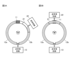
- 3A and 3B are diagrams illustrating the operation of the rotary coupler according to the first embodiment, in which the coupling portion of the rotary part is not opposed to the lossy medium of the fixed part, and the coupling portion of the rotary part is opposed to the lossy medium of the fixed part.
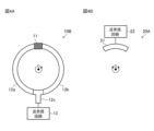
- 4A and 4B are diagrams showing the configurations of a fixed section and a rotating section in a rotary coupler according to embodiment 2.
- FIG. 4A is a schematic diagram showing the configuration of the fixed section
- Fig. 4B is a schematic diagram showing the configuration of the rotating section.
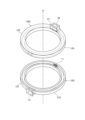
- FIG. 11 is an exploded perspective view of a rotary coupler according to a third embodiment.
- 6A and 6B are diagrams illustrating a configuration of a rotary coupler according to a third embodiment, in which Fig. 6A is a plan view of the rotary coupler, and Fig. 6B is a cross-sectional view taken along the line VI-VI in Fig. 6A.
- Embodiment 1 A rotary coupler according to a first embodiment will be described with reference to FIGS. 1 to 3.
- FIG. 1 A rotary coupler according to a first embodiment will be described with reference to FIGS. 1 to 3.
- FIG. 1 A rotary coupler according to a first embodiment will be described with reference to FIGS. 1 to 3.
- FIG. 1 A rotary coupler according to a first embodiment will be described with reference to FIGS. 1 to 3.
- Fig. 1 is a schematic diagram of the rotary coupler according to the first embodiment.
- Fig. 2 is a diagram showing the configuration of the fixed part 10A and the rotating part 20A according to the first embodiment.
- the rotary coupler As shown in FIG. 1, the rotary coupler according to the first embodiment includes a fixed portion 10A and a rotating portion 20A. This rotary coupler transmits and receives signals (e.g., high-frequency signals) between the fixed portion 10A and the rotating portion 20A using electromagnetic coupling.
- signals e.g., high-frequency signals
- the fixed part 10A and the rotating part 20A are arranged coaxially and are separated from each other with a certain gap in the axial direction.
- the rotating part 20A rotates around the central axis O (see FIG. 2) of the rotary coupler relative to the fixed part 10A.
- the arrow surrounding the central axis O indicates the rotation direction of the rotating part 20A.
- the rotating part 20A can rotate both clockwise and counterclockwise.
- the fixed part 10A has a lossy medium 11, a first waveguide 12a (hereinafter simply referred to as waveguide 12a), a second waveguide 12b (hereinafter simply referred to as waveguide 12b), and a transmission/reception circuit 13.
- the transmission/reception circuit 13 constitutes the fixed side transmission/reception circuit.
- Both the waveguides 12a and 12b are arc-shaped and have the same diameter. Furthermore, the waveguides 12a and 12b are arranged on the same plane and are coaxial with the central axis O. Therefore, the waveguides 12a and 12b are arranged facing each other, and as a whole, they form a substantially circular arc shape.
- One end of the waveguide 12a and one end of the waveguide 12b are connected via a lossy medium 11. Meanwhile, the other end of the waveguide 12a and the other end of the waveguide 12b are each connected to a transmitting/receiving circuit 13.
- the rotating part 20A has a coupling part 21 and a transmitting/receiving circuit 22.
- the transmitting/receiving circuit 22 constitutes the rotating side transmitting/receiving circuit.
- the coupling portion 21 is a transmission line.
- the coupling portion 21 is arc-shaped and has the same diameter as the diameter D of the waveguides 12a and 12b.
- the length of the coupling portion 21 is different from the lengths of the waveguides 12a and 12b. Specifically, the length of the coupling portion 21 is shorter than the lengths of the waveguides 12a and 12b.
- the coupling portion 21 is also arranged coaxially with the central axis O. That is, the waveguides 12a and 12b, and the coupling portion 21 are arranged coaxially. Furthermore, the coupling portion 21 is connected to the transmission/reception circuit 22.
- the coupling portion 21 rotates together with the rotation of the rotating portion 20A around the central axis O. At this time, the coupling portion 21 faces at least one of the waveguides 12a and 12b in the axial direction. Therefore, the coupling portion 21 is electrically coupled to at least one of the waveguides 12a and 12b. As a result, signals are transmitted and received between the transmission/reception circuit 13 of the fixed portion 10A and the transmission/reception circuit 22 of the rotating portion 20A.
- FIG. 3 is a diagram showing the operation of the rotary coupler according to the first embodiment. Note that the white arrows shown in FIG. 1 and FIG. 3 indicate the flow of signals.
- Figure 3A is a diagram showing a state in which the coupling part 21 of the rotating part 20A does not face the lossy medium 11 of the fixed part 10A.
- the signal output from the transmission/reception circuit 13 of the fixed part 10A is in phase with the other end of the waveguide 12a and the other end of the waveguide 12b and is split into two.
- the signal distributed to the other end of waveguide 12a is transmitted along the length of waveguide 12a and then absorbed by lossy medium 11.
- the signal distributed to the other end of waveguide 12b is transmitted along the length of waveguide 12b and then reaches coupling section 21. Therefore, the signal that reaches coupling section 21 is electromagnetically coupled with coupling section 21 and transmitted to transmission/reception circuit 22.
- Such a signal that travels from transmission/reception circuit 13, through waveguide 12b, through coupling section 21, and to transmission/reception circuit 22 is transmitted without discontinuity in the electromagnetic field distribution and as a wideband signal.
- Figure 3B is a diagram showing the state in which the coupling part 21 of the rotating part 20A faces the lossy medium 11 of the fixed part 10A.
- the signal output from the transmission/reception circuit 13 of the fixed part 10A is in phase with the other end of the waveguide 12a and the other end of the waveguide 12b and is split into two.
- the signal distributed to the other end of the waveguide 12a is transmitted along the length of the waveguide 12a before reaching the coupling section 21.
- the signal distributed to the other end of the waveguide 12b is transmitted along the length of the waveguide 12b before reaching the coupling section 21.
- the signal transmitted from waveguide 12a and the signal transmitted from waveguide 12b are combined in phase because waveguides 12a and 12b are electromagnetically coupled to coupling section 21.
- the combined signal is then transmitted to transmission/reception circuit 22.
- Such a signal that travels from transmission/reception circuit 13, through waveguides 12a and 12b, through coupling section 21, and to transmission/reception circuit 22 is transmitted as a wideband signal without discontinuity in the electromagnetic field distribution.
- the rotary coupler according to embodiment 1 does not cause discontinuity in the electromagnetic field distribution when the coupling unit 21 is placed at a rotational angle position other than directly above the lossy medium 11. Furthermore, when the rotary coupler according to embodiment 1 is placed at a rotational angle position corresponding to directly above the lossy medium 11, the signals from both are combined in phase by electromagnetic coupling between the waveguides 12a, 12b and the coupling unit 21. Therefore, the rotary coupler according to embodiment 1 can transmit and receive signals between the fixed unit 10A and the rotating unit 20A regardless of the rotational angle position of the rotating unit 20A.
- the rotary coupler is a rotary coupler that uses electromagnetic coupling to transmit and receive signals between the fixed part 10A and the rotating part 20A that is rotatably supported by the fixed part 10A.
- the fixed part 10A has waveguides 12a and 12b that have the same diameter, are arc-shaped, and are arranged facing each other with the central axis O as the center, a lossy medium 11 to which one end of the waveguide 12a and one end of the waveguide 12b are connected, and a transmission/reception circuit 13 to which the other end of the waveguide 12a and the other end of the waveguide 12b are connected.
- the rotating part 20A rotates around the central axis O as the center of rotation, and has a coupling part 21 that electromagnetically couples with at least one of the waveguides 12a and 12b, and a transmission/reception circuit 22 that is connected to the coupling part 21 and transmits and receives signals between the transmission/reception circuit 13. Therefore, the rotary coupler according to embodiment 1 can transmit and receive signals between the fixed part 10A and the rotating part 20A at all rotation angle positions of the rotating part 20A.
- FIG. 4 is a diagram showing the configuration of a fixed section 10B and a rotating section 20A in the rotary coupler according to the second embodiment. Note that components having the same functions as those described in the first embodiment are given the same reference numerals, and the description thereof will be omitted.
- the rotary coupler according to the second embodiment includes a fixed portion 10B and a rotating portion 20A.
- This rotary coupler transmits and receives signals between the fixed portion 10B and the rotating portion 20A using electromagnetic coupling.
- the rotary coupler according to the second embodiment has a structure including a fixed portion 10B instead of the fixed portion 10A of the rotary coupler according to the first embodiment.
- the fixed part 10B has a lossy medium 11, a waveguide 12a, a waveguide 12b, a branch part 12c, and a transmitting/receiving circuit 13.
- the waveguide 12a, the waveguide 12b, and the branch portion 12c are assumed to be microstrip lines, and the lossy medium 11 is assumed to be a terminator. Therefore, the rotary coupler can easily manufacture the waveguide 12a, the waveguide 12b, and the branch portion 12c. Furthermore, by using the lossy medium 11 as a terminator, the rotary coupler can prevent unwanted reflection of signals at the ends of the microstrip lines (the tips of the waveguide 12a and the waveguide 12b).
- the branch portion 12c is formed in a T-shape or a bifurcated shape.
- the base end of the branch portion 12c is connected to the transmission/reception circuit 13.
- the two ends of the branch portion 12c are connected to the other end of the waveguide 12a and the other end of the waveguide 12b, respectively.
- the rotating section 20A has a coupling section 21 and a transmitting/receiving circuit 22.
- the coupling section 21 is assumed to be a probe using a microstrip line.
- the position of the probe is disposed on the rotation radius (diameter dimension D) of the lossy medium 11, the waveguide 12a, the waveguide 12b, and the branch section 12c.
- the rotary coupler is capable of adjusting the position of the probe as appropriate, so long as it is within a range in which the desired amount of electromagnetic coupling can be obtained.
- the transmission line used in the probe may be in a form other than a microstrip line. It is also preferable that the transmission line used in the probe does not resonate at the frequency used. For example, if the transmission line is linear, the length of the transmission line may be set to be equal to ⁇ /2.
- the rotary coupler according to embodiment 2 does not cause discontinuity in the electromagnetic field distribution when the coupling unit 21 is placed at a rotational angle position other than directly above the lossy medium 11. Furthermore, when the rotary coupler according to embodiment 2 is placed at a rotational angle position corresponding to directly above the lossy medium 11, the signals from both are combined in phase by electromagnetic coupling between the waveguides 12a, 12b and the coupling unit 21. Therefore, the rotary coupler according to embodiment 2 can transmit and receive signals between the fixed unit 10B and the rotating unit 20A regardless of the rotational angle position of the rotating unit 20A.
- the rotary coupler according to the second embodiment is a rotary coupler that uses electromagnetic coupling to transmit and receive signals between the fixed part 10B and the rotating part 20A that is rotatably supported by the fixed part 10B.
- the fixed part 10B has waveguides 12a and 12b that have the same diameter, are arc-shaped, and are arranged facing each other with the central axis O as the center, a lossy medium 11 to which one end of the waveguide 12a and one end of the waveguide 12b are connected, and a transmission/reception circuit 13 to which the other end of the waveguide 12a and the other end of the waveguide 12b are connected.
- the rotating part 20A rotates around the central axis O as the center of rotation, and has a coupling part 21 that electromagnetically couples with at least one of the waveguides 12a and 12b, and a transmission/reception circuit 22 that is connected to the coupling part 21 and transmits and receives signals between the transmission/reception circuit 13. Therefore, the rotary coupler according to embodiment 2 can transmit and receive signals between the fixed part 10B and the rotating part 20A at all rotation angle positions of the rotating part 20A.
- FIG. 5 is an exploded perspective view of the rotary coupler according to the third embodiment.
- Fig. 6 is a diagram showing the configuration of the rotary coupler according to the third embodiment. Note that components having the same functions as those described in the first embodiment above are given the same reference numerals, and the description thereof will be omitted.
- the rotary coupler includes a fixed portion 10C and a rotating portion 20C.
- This rotary coupler transmits and receives signals between the fixed portion 10C and the rotating portion 20C using electromagnetic coupling.
- the fixed section 10C has a lossy medium 11, a first fixed-side half-waveguide 121 of the waveguide 12a (hereinafter simply referred to as the fixed-side half-waveguide 121), a second fixed-side half-waveguide 123 of the waveguide 12b (hereinafter simply referred to as the fixed-side half-waveguide 123), and a transmitting/receiving circuit 13.
- the fixed section 10C assumes that the lossy medium 11 is a radio wave absorber.
- the rotating section 20C has a coupling section 21, a transmitting/receiving circuit 22, a first rotating-side half-waveguide 122 of the waveguide 12a (hereinafter simply referred to as the rotating-side half-waveguide 122), and a second rotating-side half-waveguide 124 of the waveguide 12b (hereinafter simply referred to as the rotating-side half-waveguide 124).
- the waveguide 12a has a half structure (or a divided structure) in the axial direction, with the boundary between the fixed part 10C and the rotating part 20C.
- This waveguide 12a is divided into a fixed-side half waveguide 121 and a rotating-side half waveguide 122.
- the fixed-side half waveguide 121 and the rotating-side half waveguide 122 are both groove-shaped, and are arranged so that their openings face each other in the axial direction. Therefore, a hollow section that serves as a waveguide is formed between them.
- the waveguide 12b has a half structure (or a divided structure) in the axial direction, with the boundary between the fixed part 10C and the rotating part 20C.
- This waveguide 12b is divided into a fixed-side half waveguide 123 and a rotating-side half waveguide 124.
- the fixed-side half waveguide 123 and the rotating-side half waveguide 124 are both groove-shaped, and are arranged so that their openings face each other in the axial direction. Therefore, a hollow section that serves as a waveguide is formed between them.
- One end of the fixed-side half-split waveguide 121 and one end of the fixed-side half-split waveguide 123 are connected via a lossy medium 11.
- the other end of the fixed-side half-split waveguide 121 and the other end of the fixed-side half-split waveguide 123 are each connected to the transmission/reception circuit 13.
- the other end of the fixed-side half-split waveguide 121 and the other end of the fixed-side half-split waveguide 123 may also be connected to the transmission/reception circuit 13 via a branch portion 12c.
- one end of the rotating side half-split waveguide 122 and one end of the rotating side half-split waveguide 124 are connected via a coupling portion 21.
- the other end of the fixed side half-split waveguide 121 and the other end of the fixed side half-split waveguide 123 are connected to each other.
- the rotary coupler according to embodiment 3 does not cause discontinuity in the electromagnetic field distribution when the coupling unit 21 is placed at a rotational angle position other than directly above the lossy medium 11. Furthermore, when the rotary coupler according to embodiment 3 is placed at a rotational angle position corresponding to directly above the lossy medium 11, the signals from both are combined in phase by electromagnetic coupling between the waveguides 12a, 12b and the coupling unit 21. Therefore, the rotary coupler according to embodiment 3 can transmit and receive signals between the fixed unit 10C and the rotating unit 20C regardless of the rotational angle position of the rotating unit 20C.
- the fixed part 10C includes a fixed-side half-slit waveguide 121 that constitutes the waveguide 12a, a fixed-side half-slit waveguide 123 that constitutes the waveguide 12b, a lossy medium 11 to which one end of the fixed-side half-slit waveguide 121 and one end of the fixed-side half-slit waveguide 123 are connected, and a transmission/reception circuit 13 to which the other end of the fixed-side half-slit waveguide 121 and the other end of the fixed-side half-slit waveguide 123 are connected.
- the rotating unit 20C has a rotating half-waveguide 122 constituting the waveguide 12a, a rotating half-waveguide 124 constituting the waveguide 12b, a coupling unit 21 to which one end of the rotating half-waveguide 122 and one end of the rotating half-waveguide 124 are connected and which rotates about the central axis O as the center of rotation and which electromagnetically couples with at least one of the fixed half-waveguide 121 and the fixed half-waveguide 123, and a transmission/reception circuit 22 connected to the coupling unit 21 and which transmits and receives signals with the transmission/reception circuit 13. Therefore, the rotary coupler according to the third embodiment can transmit and receive signals between the fixed unit 10C and the rotating unit 20C at all rotation angle positions of the rotating unit 20C.
Landscapes
- Waveguide Connection Structure (AREA)
Abstract
Ce coupleur rotatif utilise un couplage électromagnétique pour émettre et recevoir des signaux entre une partie fixe (10A) et une partie rotative (20A) qui est supportée de manière rotative par rapport à la partie fixe (10A). La partie fixe (10A) comporte des guides d'ondes (12a, 12b) qui ont le même diamètre et sont disposés autour d'un axe central (O) de manière à se faire face selon une forme arquée, un milieu à perte (11) auquel sont connectées une extrémité du guide d'ondes (12a) et une extrémité du guide d'ondes (12b), et un circuit d'émission/réception (13) auquel sont connectées l'autre extrémité du guide d'ondes (12a) et l'autre extrémité du guide d'ondes (12b). La partie rotative (20A) comporte une partie de couplage (21) qui tourne autour de l'axe central (O) et se couple électromagnétiquement avec au moins l'un des guides d'ondes (12a, 12b), et un circuit d'émission/réception (22) qui est connecté à la partie de couplage (21) et émet/reçoit des signaux vers le/en provenance du circuit d'émission/réception (13).
Priority Applications (3)
| Application Number | Priority Date | Filing Date | Title |
|---|---|---|---|
| PCT/JP2023/022337 WO2024257320A1 (fr) | 2023-06-16 | 2023-06-16 | Coupleur rotatif |
| JP2024575368A JP7651083B1 (ja) | 2023-06-16 | 2023-06-16 | 回転結合器 |
| TW112147865A TW202501875A (zh) | 2023-06-16 | 2023-12-08 | 旋轉耦合器 |
Applications Claiming Priority (1)
| Application Number | Priority Date | Filing Date | Title |
|---|---|---|---|
| PCT/JP2023/022337 WO2024257320A1 (fr) | 2023-06-16 | 2023-06-16 | Coupleur rotatif |
Publications (1)
| Publication Number | Publication Date |
|---|---|
| WO2024257320A1 true WO2024257320A1 (fr) | 2024-12-19 |
Family
ID=93851725
Family Applications (1)
| Application Number | Title | Priority Date | Filing Date |
|---|---|---|---|
| PCT/JP2023/022337 Ceased WO2024257320A1 (fr) | 2023-06-16 | 2023-06-16 | Coupleur rotatif |
Country Status (3)
| Country | Link |
|---|---|
| JP (1) | JP7651083B1 (fr) |
| TW (1) | TW202501875A (fr) |
| WO (1) | WO2024257320A1 (fr) |
Citations (3)
| Publication number | Priority date | Publication date | Assignee | Title |
|---|---|---|---|---|
| JPH0445505A (ja) * | 1990-06-13 | 1992-02-14 | Sony Corp | 回転結合器 |
| JPH09500513A (ja) * | 1994-04-17 | 1997-01-14 | ウルリヒ シュヴァーン | データ伝送装置 |
| US20200212528A1 (en) * | 2019-01-02 | 2020-07-02 | ThinKom Solutions, Inc | Compact concentric split ring waveguide rotary joint |
-
2023
- 2023-06-16 WO PCT/JP2023/022337 patent/WO2024257320A1/fr not_active Ceased
- 2023-06-16 JP JP2024575368A patent/JP7651083B1/ja active Active
- 2023-12-08 TW TW112147865A patent/TW202501875A/zh unknown
Patent Citations (3)
| Publication number | Priority date | Publication date | Assignee | Title |
|---|---|---|---|---|
| JPH0445505A (ja) * | 1990-06-13 | 1992-02-14 | Sony Corp | 回転結合器 |
| JPH09500513A (ja) * | 1994-04-17 | 1997-01-14 | ウルリヒ シュヴァーン | データ伝送装置 |
| US20200212528A1 (en) * | 2019-01-02 | 2020-07-02 | ThinKom Solutions, Inc | Compact concentric split ring waveguide rotary joint |
Also Published As
| Publication number | Publication date |
|---|---|
| TW202501875A (zh) | 2025-01-01 |
| JPWO2024257320A1 (fr) | 2024-12-19 |
| JP7651083B1 (ja) | 2025-03-25 |
Similar Documents
| Publication | Publication Date | Title |
|---|---|---|
| JP2800636B2 (ja) | フレキシブル導波管 | |
| US5847625A (en) | Power Divider directional coupler | |
| EP0827637B1 (fr) | Coupleur haute frequence | |
| US7772940B2 (en) | Rotatable polarizer device using a hollow dielectric tube and feed network using the same | |
| JP5355643B2 (ja) | 二帯域マイクロ波放射エレメント | |
| JP4650561B2 (ja) | 移相器 | |
| JP3908071B2 (ja) | ロータリージョイント | |
| JP7651083B1 (ja) | 回転結合器 | |
| US4511868A (en) | Apparatus and method for transfer of r.f. energy through a mechanically rotatable joint | |
| US5001444A (en) | Two-frequency radiating device | |
| US5463358A (en) | Multiple channel microwave rotary polarizer | |
| US4163961A (en) | Rotary joint | |
| US4654613A (en) | Radar rotary joint | |
| KR20030035905A (ko) | 곡선 도파관 소자 및 이 소자를 포함하는 송신 디바이스 | |
| JPS5927522B2 (ja) | 回転形移相器 | |
| US4841261A (en) | Microwave rotary junction with external rotary energy coupling | |
| US2654868A (en) | Microwave rotatable joint | |
| JP7562046B2 (ja) | ロータリージョイント | |
| JP4057761B2 (ja) | 導波管接続素子、導波管接続素子のインピーダンス整合方法およびsバンドレーダ装置 | |
| JP6778703B2 (ja) | 高次モード結合器 | |
| JPH04227340A (ja) | 冗長によって保護されるマイクロ波信号用電力接続部 | |
| JPH11168308A (ja) | 同軸型電力合成器 | |
| JP3617397B2 (ja) | 誘電体線路導波管変換器、誘電体線路接続構造、1次放射器、発振器および送信装置 | |
| RU2109375C1 (ru) | Антенно-фидерное устройство с вращающимся соединением и одновременным механическим сканированием диаграммы направленности | |
| RU1787300C (ru) | Поворотное волноводное соединение |
Legal Events
| Date | Code | Title | Description |
|---|---|---|---|
| WWE | Wipo information: entry into national phase |
Ref document number: 2024575368 Country of ref document: JP |
|
| 121 | Ep: the epo has been informed by wipo that ep was designated in this application |
Ref document number: 23941622 Country of ref document: EP Kind code of ref document: A1 |
|
| NENP | Non-entry into the national phase |
Ref country code: DE |