WO2024257331A1 - Dispositif d'inspection de défauts et procédé d'inspection de défauts - Google Patents
Dispositif d'inspection de défauts et procédé d'inspection de défauts Download PDFInfo
- Publication number
- WO2024257331A1 WO2024257331A1 PCT/JP2023/022383 JP2023022383W WO2024257331A1 WO 2024257331 A1 WO2024257331 A1 WO 2024257331A1 JP 2023022383 W JP2023022383 W JP 2023022383W WO 2024257331 A1 WO2024257331 A1 WO 2024257331A1
- Authority
- WO
- WIPO (PCT)
- Prior art keywords
- sample
- detection unit
- unit
- defect inspection
- scattered light
- Prior art date
- Legal status (The legal status is an assumption and is not a legal conclusion. Google has not performed a legal analysis and makes no representation as to the accuracy of the status listed.)
- Ceased
Links
Images










Classifications
-
- G—PHYSICS
- G01—MEASURING; TESTING
- G01B—MEASURING LENGTH, THICKNESS OR SIMILAR LINEAR DIMENSIONS; MEASURING ANGLES; MEASURING AREAS; MEASURING IRREGULARITIES OF SURFACES OR CONTOURS
- G01B11/00—Measuring arrangements characterised by the use of optical techniques
- G01B11/02—Measuring arrangements characterised by the use of optical techniques for measuring length, width or thickness
- G01B11/06—Measuring arrangements characterised by the use of optical techniques for measuring length, width or thickness for measuring thickness ; e.g. of sheet material
-
- G—PHYSICS
- G01—MEASURING; TESTING
- G01N—INVESTIGATING OR ANALYSING MATERIALS BY DETERMINING THEIR CHEMICAL OR PHYSICAL PROPERTIES
- G01N21/00—Investigating or analysing materials by the use of optical means, i.e. using sub-millimetre waves, infrared, visible or ultraviolet light
- G01N21/84—Systems specially adapted for particular applications
- G01N21/88—Investigating the presence of flaws or contamination
- G01N21/95—Investigating the presence of flaws or contamination characterised by the material or shape of the object to be examined
- G01N21/956—Inspecting patterns on the surface of objects
-
- G—PHYSICS
- G02—OPTICS
- G02B—OPTICAL ELEMENTS, SYSTEMS OR APPARATUS
- G02B5/00—Optical elements other than lenses
Definitions
- the present invention relates to a defect inspection device and a defect inspection method.
- inspections are conducted for defects on the surfaces of semiconductor substrates, thin-film substrates, etc. to maintain and improve product yields.
- Patent Document 1 is known as background technology in this technical field.
- Patent Document 1 describes a configuration "configured to divide the full collection NA of the collection subsystem into different segments and to direct the scattered light collected in the different segments to separate detectors," and as an example, describes an aperture mirror placed in the Fourier plane of the collection subsystem, saying that "the aperture mirror transmits the scattered light collected in one segment of the collection NA while reflecting the scattered light collected in another segment of the collection NA.” It also discloses a technology for suppressing surface scattering from the wafer surface by "configuring the scattered light in one of the different segments to be separated based on polarization into different portions of the scattered light.”
- the defect inspection used in the manufacturing process of semiconductors and other products requires (1) the detection of minute defects, (2) the measurement of the dimensions of detected defects with high precision, (3) the inspection of the sample non-destructively, i.e., without altering the sample, (4) the inspection results obtained when inspecting the same sample are substantially consistent with respect to, for example, the number, position, dimensions, and type of defects detected, and (5) the inspection of a large number of samples within a certain period of time.
- the optical path is branched using an "aperture mirror" on the Fourier plane of the objective lens to discriminate from background scattered light, and for each branched optical path, the optical path is further branched using polarized light.
- Inspection methods that branch the optical path are greatly affected by the height fluctuation of the sample surface that occurs during the inspection.
- the sample rotates at a high speed of several thousand RPM (rotations per minute), and height fluctuation occurs in the direction perpendicular to the sample surface due to the warping of the sample, the influence of the chuck, air currents, and the wobble of the rotation axis.
- this height fluctuation occurs at the highest speed, it occurs at the same frequency as the rotation of the sample.
- This height fluctuation causes the focus of the sample surface relative to the detection system to shift, reducing the resolution of the image on the sensor surface. As a result, the image does not fit in the pixel, and the signal output by the pixel decreases.
- the present invention is a defect inspection device that has an illumination unit that irradiates a sample with light emitted from a light source, a detection unit that detects scattered light generated from the sample, a sample height detection unit that measures the amount of sample movement in a direction perpendicular to the sample surface, a photoelectric conversion unit that converts the scattered light detected by the detection unit into an electrical signal, and a signal processing unit that processes the electrical signal converted by the photoelectric conversion unit to detect defects in the sample, the detection unit has a mechanism that adjusts the position after branching an aperture in response to the amount of sample surface movement acquired by the sample height detection unit, and a mechanism that branches the aperture to separate and detect the scattered light generated from the sample at multiple detection elevation angles, and the signal processing unit has a mechanism that corrects the positions of multiple images formed by branching the aperture in response to the amount of sample surface movement acquired by the sample height detection unit.
- the present invention provides a defect inspection device and defect inspection method that can reduce the effect of height variations on the sample surface and achieve high sensitivity.
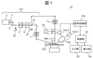
- FIG. 1 is a schematic diagram illustrating an overall configuration of a defect inspection device according to a first embodiment.
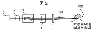
- 5A and 5B are diagrams illustrating a first example of an illumination intensity distribution shape realized by an illumination unit in the first embodiment.
- 6 is a diagram showing a second example of an illumination intensity distribution shape realized by the illumination unit in the first embodiment.
- FIG. 13 is a diagram showing a third example of an illumination intensity distribution shape realized by the illumination unit in the first embodiment.
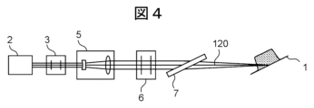
- FIG. 13 is a diagram showing a fourth example of an illumination intensity distribution shape realized by the illumination unit in the first embodiment.
- FIG. FIG. 13 is a diagram illustrating a fifth example of an illumination intensity distribution shape realized by the illumination unit in the first embodiment.
- 5A and 5B are diagrams illustrating optical elements included in the illumination intensity distribution control unit in the first embodiment.
- 5A and 5B are diagrams showing an illumination distribution shape and a scanning direction on a sample surface in Example 1.
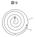
- 5A and 5B are diagrams illustrating trajectories of illumination spots caused by scanning in the first embodiment.
- 4 is a side view showing the arrangement and detection direction of a detection unit in the first embodiment.
- FIG. 4 is a plan view showing the arrangement and detection direction of a detection unit in the first embodiment.
- FIG. 2 is a configuration diagram of a detection unit in the first embodiment. 4 is a diagram showing the arrangement of illumination spots and photoelectric conversion units in the first embodiment.
- FIG. 14 is a view of FIG. 13 as seen from above on the paper surface.
- FIG. 2 is a schematic diagram showing the three-dimensional arrangement of a sample and a detection unit in the first embodiment.
- FIG. 2 is a diagram showing a cross section of a photoelectric conversion unit in the first embodiment.
- 4 is a diagram showing the relationship between the absorptance of the antireflection film of the photoelectric conversion unit and the angle of incidence in Example 1.
- FIG. FIG. 2 is a schematic diagram of a sample height detection unit in the first embodiment.
- 1A and 1B are diagrams illustrating the configuration of a detection unit in the first embodiment, and are diagrams for explaining the height direction displacement of a sample surface, the imaging position shift, and the imaging blur.
- 11A and 11B are diagrams illustrating an imaging position shift and an imaging blur at a high-angle detection unit before a height displacement in the first embodiment.
- FIG. 11A and 11B are diagrams illustrating an imaging position shift and an imaging blur at a high-angle detection unit after a height change in the first embodiment.
- 11A and 11B are diagrams illustrating an imaging position shift and an imaging blur at a low-angle detection unit before a height displacement in the first embodiment.
- 11A and 11B are diagrams illustrating an imaging position shift and an imaging blur at a low-angle detection unit after a height change in the first embodiment.
- FIG. 4 is a functional block diagram illustrating details of a signal processing unit in the first embodiment.
- FIG. 11 is a configuration diagram of a detection unit in the second embodiment, illustrating the height direction displacement of a sample surface and details of an optical element adjustment mechanism.
- FIG. 11 is a functional block diagram of a signal processing unit in the second embodiment.
- FIG. 11 is a functional block diagram of another signal processing unit in the second embodiment.
- 13 is a diagram illustrating a cross-correlation filter by a filter processing unit in the third embodiment.
- FIG. 13 is a diagram illustrating a cross-correlation filter by a filter processing unit in the third embodiment.
- FIG. 11 is a functional block diagram of a signal processing unit in the third embodiment.
- FIG. 13 is a configuration diagram of a detection unit in the fourth embodiment.
- FIG. 13 is a functional block diagram of a signal processing unit in the fifth embodiment.
- FIG. 23 is a configuration diagram of a detection unit in the sixth embodiment.
- FIG. 1 is a schematic diagram of the entire configuration of the defect inspection device in this embodiment.
- the defect inspection device 10 has an illumination unit 101, a detection unit 102, photoelectric conversion units 103-1 and 103-2 (hereinafter, these may be collectively referred to as photoelectric conversion unit 103), a stage 104 on which a sample 1 can be placed and which can be moved in a direction perpendicular to the surface by an actuator, a signal processing unit 105, a sample height detection unit 106, a control unit 53, a display unit 54, and an input unit 55.
- the illumination unit 101 appropriately comprises a laser light source 2, an attenuator 3, an emitted light adjustment unit 4, a beam expander 5, a polarization control unit 6, and an illumination intensity distribution control unit 7.
- the laser light beam emitted from the laser light source 2 is adjusted to a desired beam intensity by the attenuator 3, adjusted to a desired beam position and beam traveling direction by the emitted light adjustment unit 4, adjusted to a desired beam diameter by the beam expander 5, adjusted to a desired polarization state by the polarization control unit 6, and adjusted to a desired intensity distribution by the illumination intensity distribution control unit 7, and illuminated onto the inspection target area of the sample 1.
- the angle of incidence of the illumination light on the sample surface is determined by the position and angle of the reflecting mirror of the output light adjustment unit 4 arranged in the optical path of the illumination unit 101.
- the angle of incidence of the illumination light is set to an angle suitable for detecting minute defects.
- the larger the illumination incidence angle that is, the smaller the illumination elevation angle (angle between the sample surface and the illumination optical axis), the weaker the scattered light (called haze) from minute irregularities on the sample surface, which becomes noise in the scattered light from minute foreign objects on the sample surface, and the more suitable it is for detecting minute defects.
- the incidence angle of the illumination light is preferably set to 75 degrees or more (elevation angle 15 degrees or less).
- the incidence angle of the illumination light is preferably set to 60 degrees or more and 75 degrees or less (elevation angle 15 degrees or more and 30 degrees or less).
- the polarization control in the polarization control unit 6 of the illumination unit 101 allows the illumination polarization to be P-polarized, which increases the scattered light from defects on the sample surface compared to other polarizations.
- the illumination polarization can be set to S-polarized, which reduces the scattered light from minute irregularities on the sample surface compared to other polarizations.
- a mirror 21 can be inserted in the optical path of the illumination unit 101 and other mirrors can be positioned as appropriate to change the illumination optical path and irradiate the sample surface with illumination light from a direction substantially perpendicular to the sample surface (perpendicular illumination).
- the illumination intensity distribution on the sample surface is controlled by the illumination intensity distribution control unit 7v in the same way as for oblique incidence illumination.
- vertical illumination that is substantially perpendicular to the sample surface is suitable for obtaining oblique incidence illumination and scattered light from concave defects on the sample surface (polishing scratches and crystal defects in crystalline materials).
- the laser light source 2 is one that emits a short-wavelength (355 nm or less) ultraviolet or vacuum ultraviolet laser beam with a high output of 2 W or more, as this is a wavelength that does not easily penetrate into the sample.
- the emitted beam diameter is about 1 mm.
- a visible or infrared laser beam with a wavelength that easily penetrates into the sample is used.
- the attenuator 3 is appropriately equipped with a first polarizing plate, a half-wave plate that can rotate around the optical axis of the illumination light, and a second polarizing plate.
- the light incident on the attenuator 3 is converted into linearly polarized light by the first polarizing plate, and the polarization direction is rotated in an arbitrary direction according to the slow axis azimuth angle of the half-wave plate, and passes through the second polarizing plate.
- the azimuth angle of the half-wave plate By controlling the azimuth angle of the half-wave plate, the light intensity is reduced at an arbitrary ratio. If the degree of linear polarization of the light incident on the attenuator 3 is sufficiently high, the first polarizing plate is not necessarily required.
- the attenuator 3 used has a relationship between the input signal and the light reduction rate calibrated in advance.
- the output light adjustment unit 4 is equipped with multiple reflecting mirrors.
- an example is described in which it is configured with two reflecting mirrors, but this is not limited to this, and three or more reflecting mirrors may be used as appropriate.
- a three-dimensional Cartesian coordinate system (XYZ coordinates) is provisionally defined, and it is assumed that the light incident on the reflecting mirror travels in the +X direction.
- the first reflecting mirror is installed to deflect the incident light in the +Y direction (incident and reflected in the XY plane), and the second reflecting mirror is installed to deflect the light reflected by the first reflecting mirror in the +Z direction (incident and reflected in the YZ plane).
- the position and traveling direction (angle) of the light emitted from the output light adjustment unit 4 are adjusted by translating each reflecting mirror and adjusting the tilt angle.
- XY plane entrance/reflection surface
- YZ plane entrance/reflection surface
- the beam expander 5 has two or more lens groups and has the function of expanding the diameter of the parallel light beam incident thereon.
- a Galilean type beam expander having a combination of concave and convex lenses is used.
- the beam expander 5 is installed on a translation stage with two or more axes, and its position can be adjusted so that its center coincides with a specified beam position.
- the beam expander 5 is provided with a function for adjusting the tilt angle of the entire beam expander 5 so that the optical axis of the beam expander 5 coincides with a specified beam optical axis.
- the expansion rate of the light beam diameter can be controlled by adjusting the lens spacing (zoom mechanism).
- the diameter of the light beam is expanded and collimated (the light beam is made quasi-parallel) at the same time by adjusting the lens spacing.
- the light beam can be collimated by installing a collimating lens upstream of the beam expander 5 independently of the beam expander 5.
- the beam diameter expansion factor of the beam expander 5 is about 5 to 10 times, so the beam emitted from the light source with a diameter of 1 mm is expanded to about 5 to 10 mm.
- the polarization control unit 6 is composed of a half-wave plate and a quarter-wave plate, and controls the polarization state of the illumination light to any polarization state. In the middle of the optical path of the illumination unit 101, the state of the light incident on the beam expander 5 and the light incident on the illumination intensity distribution control unit 7 is measured by the beam monitor 22.
- FIGS. 2 to 6 are schematic diagrams showing the positional relationship between the illumination optical axis 120 guided to the sample surface from the illumination unit 101 and the illumination intensity distribution shape. Note that the configuration of the illumination unit 101 in FIG. 2 to FIG. 6 shows only a part of the configuration of the illumination unit 101, and the emitted light adjustment unit 4, mirror 21, beam monitor 22, etc. are omitted.
- FIG. 2 is a schematic diagram of a cross section of the incidence plane (plane including the illumination optical axis and the sample surface normal) of the oblique incidence illumination in this embodiment.
- the oblique incidence illumination is inclined with respect to the sample surface within the incidence plane.
- the illumination unit 101 creates a substantially uniform illumination intensity distribution within the incidence plane.
- the length of the part with uniform illumination intensity is approximately 100 ⁇ m to 4 mm in order to inspect a wide area per unit time.
- FIG. 3 is a schematic diagram of a cross section of a plane that includes the sample surface normal and is perpendicular to the incident plane of oblique incidence illumination in this embodiment.
- the illumination intensity distribution on the sample surface forms an illumination intensity distribution in which the intensity is weaker at the periphery than at the center. More specifically, the intensity distribution is similar to a Gaussian distribution that reflects the intensity distribution of the light incident on the illumination intensity distribution control unit 7, or a first-order Bessel function of the first kind or a sinc function that reflects the aperture shape of the illumination intensity distribution control unit 7.
- the length of the illumination intensity distribution within this plane (the length of the region with an illumination intensity of 13.5% or more of the maximum illumination intensity) is shorter than the length of the portion in the incident plane where the illumination intensity is uniform, and is approximately 2.5 ⁇ m to 20 ⁇ m, in order to reduce haze generated from the sample surface.
- the illumination intensity distribution control unit 7 includes optical elements such as an aspheric lens, a diffractive optical element, a cylindrical lens array, and a light pipe, which will be described later.
- the optical elements that make up the illumination intensity distribution control unit 7 are installed perpendicular to the illumination optical axis, as shown in Figures 2 and 3.
- the illumination intensity distribution control unit 7 includes optical elements that act on the phase distribution and intensity distribution of the incident light.
- FIG. 7 is a diagram showing the optical elements included in the illumination intensity distribution control unit 7 in this embodiment.
- a diffractive optical element 71 DOE: Diffractive Optical Element
- the diffractive optical element 71 is formed by forming a fine undulating shape with dimensions equal to or smaller than the wavelength of light on the surface of a substrate made of a material that transmits incident light. As a material that transmits incident light, fused quartz is used for ultraviolet light.
- the diffractive optical element 71 In order to suppress attenuation of light due to passing through the diffractive optical element 71, it is preferable to use one that is coated with an anti-reflection film.
- the fine undulating shape is formed by using a lithography method. By passing the light that has become quasi-parallel light after passing through the beam expander 5 through the diffractive optical element 71, an illumination intensity distribution on the sample surface according to the undulating shape of the diffractive optical element 71 is formed.
- the undulating shape of the diffractive optical element 71 is designed and manufactured to a shape calculated based on Fourier optics theory so that the illumination intensity distribution formed on the sample surface is a long and uniform distribution within the incident surface.
- the optical element provided in the illumination intensity distribution control unit 7 is provided with a translation adjustment mechanism with two or more axes and a rotation adjustment mechanism with two or more axes so that the relative position and angle with respect to the optical axis of the incident light can be adjusted.
- a focus adjustment mechanism by movement in the optical axis direction is provided.
- an aspheric lens, a combination of a cylindrical lens array and a cylindrical lens, or a combination of a light pipe and an imaging lens may be used as an alternative optical element having the same function as the diffractive optical element 71.
- a Gaussian distribution illumination that is long in one direction is created by having a spherical lens in the illumination intensity distribution control unit 7 and forming an elliptical beam that is long in one direction with the beam expander 5, or by configuring the illumination intensity distribution control unit 7 with multiple lenses including a cylindrical lens.
- a part or all of the spherical lens or cylindrical lens in the illumination intensity distribution control unit 7 is placed parallel to the sample surface, thereby forming an illumination intensity distribution that is long in one direction on the sample surface and has a narrow width in the direction perpendicular to the direction.
- the illumination intensity distribution is highly stable.
- the light transmittance is high and efficiency is high compared to the case where a diffractive optical element or a microlens array is used for the illumination intensity distribution control unit 7.
- the state of the illumination light in the illumination unit 101 is measured by the beam monitor 22.
- the beam monitor 22 measures and outputs the position and angle (traveling direction) of the illumination light that has passed through the outgoing light adjustment unit 4, or the position and wavefront of the illumination light that is incident on the illumination intensity distribution control unit 7.
- the position of the illumination light is measured by measuring the center of gravity of the light intensity of the illumination light.
- Specific position measurement means include an optical position sensor (PSD: Position Sensitive Detector) or an image sensor such as a CCD sensor or CMOS sensor.
- the angle of the illumination light is measured by an optical position sensor or an image sensor installed at a position farther away from the light source than the position measurement means, or at the focusing position by a collimating lens.
- the illumination light position and illumination light angle detected by the sensor are input to the control unit 53 and displayed on the display unit 54. If the illumination light position or angle deviates from the specified position or angle, it is adjusted to return to the specified position in the outgoing light adjustment unit 4.
- the wavefront measurement of the illumination light is performed to measure the parallelism of the light incident on the illumination intensity distribution control unit 7. If the wavefront measurement shows that the light incident on the illumination intensity distribution control unit 7 is not quasi-parallel light but is diverging or converging, the lens group of the front-stage beam expander 5 can be displaced in the optical axis direction to make it closer to quasi-parallel light.
- a spatial light phase modulator which is a type of spatial light modulator (SLM: Spatial Light Modulator)
- SLM Spatial Light Modulator
- the above wavefront accuracy measurement and adjustment means suppress the wavefront accuracy of the light incident on the illumination intensity distribution control unit 7 (deviation from a predetermined wavefront (design value or initial state)) to ⁇ /10 rms or less.
- the illumination intensity distribution on the sample surface adjusted by the illumination intensity distribution control unit 7 is measured by the illumination intensity distribution monitor 24. As shown in FIG. 1, even when vertical illumination is used, the illumination intensity distribution on the sample surface adjusted by the illumination intensity distribution control unit 7v is measured by the illumination intensity distribution monitor 24.
- the illumination intensity distribution monitor 24 detects the sample surface as an image by forming an image of the sample surface on an image sensor such as a CCD sensor or CMOS sensor via a lens.
- the image of the illumination intensity distribution detected by the illumination intensity distribution monitor 24 is processed by the control unit 53, and the center position of the intensity, maximum intensity, maximum intensity position, width and length of the illumination intensity distribution (width and length of the illumination intensity distribution region where the intensity is equal to or greater than a specified intensity or a specified ratio to the maximum intensity value), etc. are calculated and displayed on the display unit 54 together with the contour shape and cross-sectional waveform of the illumination intensity distribution.
- the height displacement of the sample surface causes a displacement of the position of the illumination intensity distribution and disturbance of the illumination intensity distribution due to defocus. To prevent this, the height of the sample surface is measured, and if the height is shifted, the deviation is corrected by adjusting the height using the illumination intensity distribution control unit 7 or the Z axis of the stage 104.
- the illuminance distribution shape (illumination spot 20) formed on the sample surface by the illumination unit 101 and the sample scanning method are explained using Figures 8 and 9.
- Stage 104 is equipped with a translation stage, a rotation stage, and a Z stage for adjusting the height of the sample surface (none of which are shown).
- illumination spot 20 has a long illumination intensity distribution in one direction, which direction is designated as S2, and a direction substantially perpendicular to S2 is designated as S1.
- the rotational motion of the rotation stage scans in the circumferential direction S1 of a circle centered on the rotation axis of the rotation stage, and the translational motion of the translation stage scans in the translation direction S2 of the translation stage.
- the illumination spot 20 is scanned in scanning direction S2 by a distance equal to or less than the longitudinal length of the illumination spot 20, so that the illumination spot traces a spiral trajectory T on the sample 1, and the entire surface of the sample 1 is scanned.
- a plurality of detection units 102 are arranged so as to detect scattered light in a plurality of directions emanating from the illumination spot 20.
- An example of the arrangement of the detection units 102 with respect to the sample 1 and illumination spot 20 will be described with reference to Figs. 10 to 12.
- Figure 10 shows a side view of the arrangement of the detection unit 102.
- the angle between the normal to the sample 1 and the detection direction (the direction of the center of the detection aperture) by the detection unit 102 is defined as the detection zenith angle.
- the detection unit 102 is composed of a high-angle detection unit 102h with a detection zenith angle of 45 degrees or less, a low-angle detection unit 102l with a detection zenith angle of 45 degrees or more, and high-angle detection unit 102h' and low-angle detection unit 102l' that are positioned symmetrically with respect to the normal to the sample 1.
- Each of the high-angle detection unit 102h and low-angle detection unit 102l detects scattered light using a common objective lens, which is branched at the Fourier plane of the objective lens. Furthermore, the detection unit 102 is composed of multiple detection units so as to cover scattered light in multiple directions.
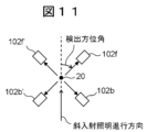
- FIG. 11 shows a plan view of the arrangement of the detection unit 102.
- the detection unit 102 appropriately comprises a front detection unit 102f, a rear detection unit 102b, and a front detection unit 102f' and a rear detection unit 102b' that are positioned symmetrically with respect to the illumination incidence plane.
- the front detection unit 102f is installed at a detection azimuth angle of 0 degrees or more and 90 degrees or less
- the rear detection unit 102b is installed at a detection azimuth angle of 90 degrees or more and 180 degrees or less.
- a low-angle detection unit and a high-angle detection unit are provided for each detection azimuth. This is not limiting, and the number and positions of the detection units may be changed as appropriate.
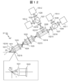
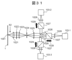
- Figure 12 is a diagram of the detection unit in this embodiment.
- scattered light generated from the illumination spot 20 is collected by the objective lens 1021.
- the detection NA of the objective lens 1021 is 0.3 or more. If necessary, the lower end of the objective lens 1021 is cut out so that it does not interfere with the sample 1.
- the imaging lens 1023 forms an image of the illumination spot 20 at the position of the aperture 1024.
- the aperture 1024 is an aperture set to pass only the light of the area detected by the photoelectric conversion unit 103 from the image of the illumination spot 20.
- the aperture 1024 passes only the central part of the Gaussian distribution where the light amount is strong in the S2 direction, and blocks the area of the beam end where the light amount is weak.
- the size of the image formed in the S1 direction is set to be approximately the same as that of the illumination spot 20, suppressing disturbances such as air scattering that occur when the illumination passes through the air.
- 1025 is a condenser lens that re-condenses the image of the aperture 1024 formed.
- the Fourier plane of the objective lens 1021 is relayed by the condenser lens 1025, and a polarization control filter 1022 is placed on the Fourier plane.
- the polarization control filter 1022 for example, a 1/2 wavelength plate whose rotation angle can be controlled by a driving mechanism such as a motor is used.
- the pupil plane is relayed by a relay lens consisting of an imaging lens 1023, a condenser lens 1025, an imaging lens 10213, and a condenser lens 10214, and a knife edge 1026 (branching optical member) is placed on the pupil plane.
- the knife edge 1026 branches the scattered light condensed to the high-angle detection unit 102h, which has a detection zenith angle of 45 degrees or less, and the low-angle detection unit 102l, which has a detection zenith angle of 45 degrees or more.
- the angles between the chief ray of the branched scattered light and the normal line of the sample surface are different, and in FIG.
- the angle between the chief ray 10218 of the scattered light detected by the low-angle detection unit 102l and the normal line 10217 of the sample surface is larger than the angle between the chief ray 10219 of the scattered light detected by the high-angle detection unit 102h and the normal line 10217 of the sample surface.
- the branching angle of the detection zenith angle is not necessarily 45 degrees and can be changed as appropriate.
- a polarizing beam splitter 1027 is installed on each pupil plane of the light that is relayed and branched by the imaging lens 10215 and the condenser lens 10216. This separates the light whose polarization direction has been converted by the polarization control filter 1022 according to the polarization direction.
- the low-angle detection unit 102l detects with the photoelectric conversion units 103-1 and 103-3.
- the high-angle detection unit 102h detects with the photoelectric conversion units 103-2 and 103-4.
- 1028 is an imaging lens that forms an image of the illumination spot 20 on the photoelectric conversion unit 103.
- a cylindrical lens can also be used as the imaging lens 1028 to form an image in only one direction.
- the combination of the polarization control filter 1022 and the polarizing beam splitter 1027 is used to detect only light of a specific polarization direction from the light collected by 1021 in the photoelectric conversion unit 103.
- the polarization control filter 1022 can be a wire grid polarizer with a transmittance of 80% or more, and only light of the desired polarization direction can be extracted without using the polarizing beam splitter 1027.
- a beam diffuser is used instead of the imaging lens 1028 to prevent unnecessary light from becoming stray light.
- Fig. 13 is a diagram showing the arrangement of the illumination spot and the photoelectric conversion unit in this embodiment.
- Fig. 14 is a diagram showing Fig. 13 as viewed from above on the paper.
- the optical axis 121 is inclined with respect to the normal direction of the light receiving unit 1031.
- the light receiving unit 1031 of the photoelectric conversion unit 103 is arranged parallel to the longitudinal direction ⁇ of the optical image 25 formed on the light receiving unit 1031 by the detection unit 102, in which the linear illumination spot 20 irradiated on the surface of the sample 1 is irradiated.
- the paired cylindrical lenses 10210 and 10211 form a cylindrical beam expander, and the spread of the optical image 25 formed by the illumination spot 20 in the short direction ⁇ is made smaller than the spread of the optical image 25 in the longitudinal direction.
- the photoelectric conversion unit 103 captures the optical image 25 and outputs it as an electrical signal.
- the photoelectric conversion unit 103 has an array of light receiving units and an anti-reflection film at a position conjugate with the illumination spot irradiated on the surface of the sample 1.
- the light receiving surface of the photoelectric conversion unit 103 is not conjugate with the sample surface in the short direction ⁇ .
- the short direction ⁇ is also the short direction of the illumination spot 20
- the image height of the optical image 25 is low and almost no defocus occurs. Therefore, by increasing the imaging magnification of the optical image 25 in the short direction ⁇ , it is possible to reduce the variation in the angle of incidence on the light receiving unit 1031.
- FIG. 15 is a schematic diagram of the three-dimensional arrangement of the sample 1 and the detection unit 102 in this embodiment.
- the optical axis 121 of the detection unit 102 shown with reference to the objective lens 1021, is inclined at an angle ⁇ with respect to the normal direction Z of the sample 1.
- the projection of the optical axis 121 onto the sample surface is inclined at an angle ⁇ with respect to the longitudinal direction S2 of the illumination spot 20.
- optical axis 121 that detects the light from the detection unit 102 is offset by an angle ⁇ with respect to the normal direction of the sample 1 and an angle ⁇ with respect to the longitudinal direction of the illumination spot 20, then in three-dimensional space, this optical axis 121 is represented by the vector v0 in the following equation (1).
- the angle ⁇ between this vector v0 and the longitudinal direction of the illumination spot 20 is calculated using the following formula (2).
- the defect inspection device 100 detects a section of 2L in the longitudinal direction of the illumination spot 20 using the photoelectric conversion unit 103.
- the working distance (the distance between the sample 1 and the detection unit 102) changes as ⁇ Z shown in the following formula (3).
- the imaging magnification M is determined by the objective lens 1021 and the imaging lens 1028.
- the position of the image formed here is expressed by the following equation (4).
- a line sensor is positioned so that it is perpendicular to the optical axis, which is the center of the light beam emitted by the imaging lens.
- the optical axis 121 incident on the photoelectric conversion unit 103 and the pixel array vector v1 of the light receiving surface are set so that they are within the plane spanned by the longitudinal direction of the illumination spot 20 and vector v0, and the angle ⁇ between vector v1 and vector v0 satisfies the following formula (5).
- angle ⁇ is the angle between vector v2 and vector v0, and satisfies equation (6).
- the imaging magnification M increases, the angle ⁇ between vectors v0 and v1 decreases, and the angle of incidence increases.
- M 2
- the light ray with the largest angle of incidence enters the photoelectric conversion unit 103 at an angle close to 90 degrees.
- the absorptance of the anti-reflection film 1033 of the photoelectric conversion unit 103 depends on the angle of incidence, and the absorptance becomes very small at angles of incidence close to 90 degrees. To prevent this, the imaging magnification M is set to 2x or less.
- the angle between the optical axis 121 incident on the photoelectric conversion unit 103 from the imaging lens 1028 and the vector v1 can be maximized.
- the numerical aperture of the incident light beam on the objective lens 1021 is N
- the spread of the light beam emitted to the photoelectric conversion unit 103 is the reciprocal of the imaging magnification M multiplied by the spread of the light beam emitted to the imaging lens 1028.
- the imaging magnification M is set to 1x or more. As a result, the angle ⁇ becomes smaller than the angle ⁇ , and typically becomes smaller by 5 degrees or more when a magnification of about 1.3x is applied.
- FIG. 16 is a cross-sectional view of the image sensor 1036 that constitutes the photoelectric conversion unit 103 in this embodiment.
- the image sensor 1036 is configured by laminating an anti-reflection film 1033, a light receiving unit 1031, and a wiring unit 1032 in this order from the surface.
- Incident light 122A to 122C is light that is incident on the image sensor 1036.
- Incoming light 122A is light on optical axis 121 shown in Figures 13 and 14.
- Incident light 122B, 122C is light that is incident from an angle different from optical axis 121.
- Anti-reflection film 1033 is a film for preventing surface reflection of each of incident light 122A to 122C.
- Light receiving section 1031 is in an array shape, and performs photoelectric conversion for each divided area, i.e., pixel.
- Wiring section 1032 independently extracts the electricity output by light receiving section 1031 to the outside.
- a sensor with such a structure in which light receiving section 1031 is on the light incident side of wiring section 1032 is known as a back side illumination sensor.
- incident light is incident at a predetermined angle shifted from the normal direction of the light receiving section.
- FSI Front Side Illumination
- incident light 122A to 122C As shown by incident light 122A to 122C, light is incident on the light receiving section 1031 from a variety of directions. Therefore, unless the anti-reflection film 1033 has a high absorption rate for these incident light beams 122A to 122C, good sensitivity cannot be obtained.
- Figure 17 is a graph showing the characteristics of an anti-reflection coating 1033 formed from a single layer of hafnium oxide HfO2, 25 nm thick.
- the horizontal axis of the graph represents the angle of incidence, and the vertical axis of the graph represents the absorptance.
- Curve 10333 represents the absorptance characteristics for S-polarized light.
- Curve 10334 represents the absorptance characteristics for P-polarized light. The absorptance of P-polarized light decreases as the angle of incidence increases, but the absorptance drops to 0.5 when the angle of incidence is around 60 degrees.
- the incidence angle of S-polarized light increases up to about 70 degrees, and in the incidence angle range of 0 to 80 degrees, an absorption rate of 70% or more is shown.
- the photoelectric conversion units 103-1 and 103-2 must be tilted by a certain angle in order to achieve image detection without focus shifting, regardless of changes in the field of view at the working distance. In other words, it is desirable to tilt the normal to the light receiving surface of the photoelectric conversion unit 103-1 by, for example, 10 to 80 degrees from the optical axis 121-1 of the detection unit 102-1.
- FIG. 18 is a schematic diagram of the sample height detection unit in this embodiment.
- the sample height detection unit 106 uses height sensors 1061-1, 1061-2, and 1061-3, such as multiple laser interferometers, to measure the height of the sample at multiple points in real time during inspection. By measuring the height displacement of the inspection area in advance before detecting the scattered light in the inspection area, delays during inspection can be prevented.
- the height displacement of the sample surface causes a displacement of the illumination intensity distribution position and disturbance of the illumination intensity distribution due to defocus.
- the height of the sample surface is measured, and if the height is shifted, the illumination intensity distribution control unit 7 or the height adjustment on the Z axis of the stage 104 is used to correct the image shift caused by the displacement of the sample surface.
- the height of the sample surface in the Z-axis direction displaces by several tens to several hundreds of ⁇ m at a frequency of several tens to several hundreds of Hz.
- causes of the displacement include misalignment of the rotation axis and vibration of the stage.
- This Z-axis displacement of the sample surface displaces the position of the image formed on the sensor surface.
- the displacement of each divided image due to the Z-axis displacement ⁇ w is shown in formula (7),
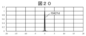
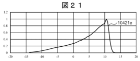
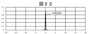
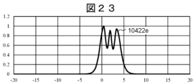
- Figures 19 to 23 are diagrams explaining the height-wise displacement of the sample surface and the shift in the imaging position.
- the image of foreign matter 1041d becomes image 10421d in Figure 20
- the image of foreign matter 1041e becomes image 10421e in Figure 21.
- the horizontal axis of each graph is the distance in the ⁇ direction of the light-receiving surface of photoelectric conversion unit 103.
- the imaging positions on the light-receiving surfaces of 10421d and 10421e are significantly different.
- FIG. 24 is a functional block diagram of the signal processing unit 105 in this embodiment.
- the sample height detection unit 106 e.g., an optical sensor detects the Z-axis displacement of the detection area on the sample surface in real time and stores it in the memory 241.
- the imaging position calculation unit 242 calculates the deviation of the imaging position from the Z-axis displacement of the detection area. For one or more of the detection point apex angles 102l with large detection point apex angles and 102h with small detection point apex angles that respectively constitute the detection units 102f, 102b, 102f', and 102b' shown in FIG. 11, the imaging in the direction of the large detection point apex angle and the signal in the direction of the small detection point apex angle are divided into two or more groups and integrated by the photoelectric conversion unit 103.
- the imaging position correction unit 243 corrects the imaging position shift of signals with large imaging position shifts (i.e., groups including many signals of scattered light with large detection point apex angles), and the signal integration unit 244 integrates the images of all groups, thereby preventing a decrease in sensitivity due to imaging position shifts.
- the mechanism of FIG. 24 can operate in real time at a frequency of several tens to several hundreds of Hz during inspection, and prevents a decrease in sensitivity to Z-axis displacement due to the inspection.
- the signal combining unit 244 can also operate as follows.
- the signal combining unit 244 groups scattered light whose detected elevation angles are similar (the difference between them is within a specified range) to form one or more scattered light groups.
- the signal combining unit 244 first combines the images of the members of each group to generate a number of provisional integrated images equal to the number of groups.
- the imaging position correction unit 243 corrects the imaging position for each provisional integrated image (i.e., group).
- the signal combining unit 244 generates a final integrated image by re-integrating each provisional integrated image after the imaging position has been corrected.
- the defect inspection device 10 is configured to detect and integrate foreign objects at the same position on the sample 1 on the same coordinates on the light receiving surface of the photoelectric conversion units 103-1 and 103-2 after branching at the knife edge 1026, using scattered light with similar angles of incidence to the condenser lens 1025, and to correct image position shifts to a greater extent for scattered light with a larger apex angle of the detection point. This allows even the smallest defects to be detected with high precision, and image shifts caused by displacement of the sample surface in the Z direction to be accurately corrected.
- the optical path is split by an optical splitting means placed at the pupil position of the focusing means, or at the position where the pupil is relayed, or in the vicinity thereof, thereby making it possible to discriminate from background scattered light.
- the photoelectric conversion unit is placed conjugate to the sample and inclined with respect to the optical axis, enabling imaging detection without blurring in the longitudinal direction of the illumination and imaging detection from a direction that is not perpendicular to the longitudinal direction of the illumination. This makes it possible to place an imaging detection system without being restricted by the azimuth angle, making it possible to image almost the entire light scattered from minute defects present on the sample surface, achieving high-speed and high-sensitivity detection.
- the signal processing unit 105 corrects the image position shift, but in this embodiment, the positions of the optical elements of the detection optical system are adjusted to correct the change in the PSF (point spread function) of the image, which is the image blur.
- PSF point spread function
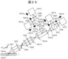
- FIG. 25 is a diagram of the detection unit 102 in this embodiment, and is a diagram for explaining the height direction displacement of the sample surface and the details of the optical element adjustment mechanism.
- the same components as in FIG. 19 are given the same reference numerals, and their explanation will be omitted.
- a mechanism 10212 for adjusting the position along the optical axis direction is attached to the imaging lens 1028 and one or more of the photoelectric conversion units 103-1 and 103-2.
- a micrometer with a piezoelectric motor can be used as the mechanism 10212 for adjusting the position.
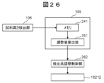
- FIG. 26 is a functional block diagram of the signal processing unit 105 in this embodiment.
- the adjustment amount calculation unit 261 calculates the adjustment distance in the optical axis direction from the Z-axis displacement of the sample surface stored in the memory 241, and the detection system adjustment control unit 262 adjusts a part of the detection unit 102 (one or more optical elements) in the optical axis direction. This reduces the difference in the changes in PSF due to the Z-axis displacement of the sample surface, reduces blurring of the integrated image, and prevents a decrease in sensitivity.
- the position of which optical element is to be adjusted can be determined as follows.
- the operation of the composite lens can be calculated. Therefore, when the position of any optical element is moved, the operation of the composite lens caused by the movement can also be calculated.
- the adjustment amount calculation unit 261 can calculate each PSF change by calculating the operation of the composite lens when, for example, one or more of the optical elements from the objective lens 1021 to the photoelectric conversion unit 103 are randomly selected and their positions are moved.
- the adjustment amount calculation unit 261 can determine the optical element to be adjusted in position and the amount of position movement by searching for a combination of optical elements and position adjustment amounts that minimize each PSF change.
- the search may be performed randomly, or a search algorithm based on an appropriate evaluation function may be used.
- the optical elements for which the PSF should be corrected with priority are predetermined (for example, optical elements with small size are given priority), the positions of those optical elements may be adjusted in order.
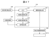
- the signal processing unit 105 may simultaneously adjust the position of the optical element and perform the signal processing described in the first embodiment to prevent a decrease in sensitivity.
- a functional block diagram of the signal processing unit in this case is shown in FIG. 27.
- the image position correction unit 243 and the adjustment amount calculation unit 261 determine the correction amount and adjustment amount for each sample height in advance. The correction amount and adjustment amount are set so that the image position shift and the change in PSF caused by the change in sample height are minimized, thereby preventing a decrease in sensitivity.
- FIG. 28 and 29 show the characteristics of the cross-correlation filter in this embodiment.
- FIG. 28 shows a cross-correlation filter corresponding to the image 10421e of scattered light with a large detection point apex angle and a large change in PSF
- FIG. 29 shows a cross-correlation filter corresponding to the image 10422e of scattered light with a small detection point apex angle.
- the 4 ⁇ Gaussian fitting curves of each image are convoluted with the signal after the image position is corrected by the image position correction unit 243. This convolution is performed in the same way before and after the sample height displacement occurs.
- the signal processing unit has a cross-correlation filter, which is a mechanism for reducing the difference in signal between when defocused and when focused.
- the shape of this cross-correlation filter can be arbitrarily determined by checking in advance the change in the image caused by the height displacement of the sample for each detection point apex angle and detection azimuth angle. In addition, by arbitrarily determining the shape of the cross-correlation filter for the amount of sample height displacement detected by the sample height detection unit 106 and multiplying it by the signal of each image, the difference in signal strength caused by the height displacement of the sample can be reduced.
- FIG. 30 is a functional block diagram of the signal processing unit in this embodiment.
- the sample height detection unit 106 e.g., an optical sensor detects the Z-axis displacement of the detection area on the sample surface in real time and stores it in the memory 241.
- the signals whose imaging positions have been corrected in the imaging position correction unit 243 are convolved with a cross-correlation filter in the filter processing unit 245.
- the convolved signals are integrated in the signal integration unit 244. It is also possible to select a cross-correlation filter according to the amount of sample height displacement in the filter selection unit 246, and perform processing in the filter processing unit 245 using the selected filter.
- the mechanism in FIG. 30 can operate in real time at a frequency of several tens to several hundreds of Hz during inspection, preventing sensitivity changes before and after Z-axis displacement due to inspection.
- the detection system is placed obliquely to the sample, but it is also possible to place the detection system perpendicular to the sample. In that case, the photoelectric conversion unit does not need to be at an angle to the optical axis, and is placed on a plane conjugate to the sample.
- FIG. 31 is a diagram showing the configuration of the detection unit in this embodiment.
- the same components as those in FIG. 12 are given the same reference numerals, and their explanations are omitted.
- 1029 is a beam diffuser, which prevents unnecessary light from becoming stray light.
- the light is branched for each detection point apex angle and detected separately.
- the detected scattered light is branched into three regions for each detection point apex angle and detected by photoelectric conversion units 103-1, 103-2, and 103-3, respectively, but the number of branches can be determined arbitrarily, and it can be branched into two or more regions.
- image shift and PSF change occur due to displacement of the sample surface, and the image shift and PSF change differ for each detection point apex angle. To prevent a decrease in sensitivity due to these, correction is performed using the configuration shown in Examples 1 to 3.
- the photoelectric conversion unit 103 does not need to be arranged at an angle to the optical axis, so it is possible to use a CCD or TDI sensor in addition to a CMOS sensor.
- Example 2 we will explain a configuration in which Example 2 and Example 3 are performed simultaneously.
- FIG. 32 is a functional block diagram of the signal processing unit in this embodiment.
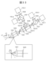
- Example 1 the configuration shown in FIG. 33 can be considered for the example of the detection unit shown in FIG. 12. That is, as shown in FIG. 33, one relay in the Fourier plane consisting of the imaging lens 10213 and the condenser lens 10214 in FIG. 12 is omitted, and the polarization control filter 1022 and the knife edge 1026 are arranged close to each other. This makes it possible to shorten the length of the entire optical system.
Landscapes
- Physics & Mathematics (AREA)
- General Physics & Mathematics (AREA)
- Optics & Photonics (AREA)
- Health & Medical Sciences (AREA)
- Life Sciences & Earth Sciences (AREA)
- Chemical & Material Sciences (AREA)
- Analytical Chemistry (AREA)
- Biochemistry (AREA)
- General Health & Medical Sciences (AREA)
- Immunology (AREA)
- Pathology (AREA)
- Investigating Materials By The Use Of Optical Means Adapted For Particular Applications (AREA)
Abstract
La présente invention concerne un dispositif d'inspection de défauts et un procédé d'inspection de défauts permettant de réduire l'influence due à la variation de hauteur d'une surface d'échantillon et d'obtenir une sensibilité élevée. Afin d'atteindre l'objectif mentionné ci-dessus, le présent dispositif d'inspection de défauts comprend : une unité d'éclairage qui irradie un échantillon avec de la lumière émise par une source de lumière; une unité de détection qui détecte la lumière diffusée générée à partir de l'échantillon; une unité de détection de hauteur d'échantillon qui mesure une quantité de variation de l'échantillon dans un sens perpendiculaire à une surface de l'échantillon; une unité de conversion photoélectrique qui convertit la lumière diffusée détectée par l'unité de détection en un signal électrique; et une unité de traitement de signal qui traite le signal électrique converti par l'unité de conversion photoélectrique pour détecter un défaut de l'échantillon. L'unité de détection comporte un mécanisme pour régler sa position après divergence à partir d'une ouverture en fonction de la quantité de variation de la surface de l'échantillon acquise par l'unité de détection de hauteur d'échantillon, et un mécanisme pour détecter séparément la lumière diffusée, qui a été générée à partir de l'échantillon après divergence depuis l'ouverture, à une pluralité d'angles d'élévation pour la détection. L'unité de traitement de signal comprend un mécanisme pour corriger les positions d'une pluralité d'images formées par divergence à partir de l'ouverture en fonction de la quantité de variation de la surface de l'échantillon acquise par l'unité de détection de hauteur d'échantillon.
Priority Applications (1)
| Application Number | Priority Date | Filing Date | Title |
|---|---|---|---|
| PCT/JP2023/022383 WO2024257331A1 (fr) | 2023-06-16 | 2023-06-16 | Dispositif d'inspection de défauts et procédé d'inspection de défauts |
Applications Claiming Priority (1)
| Application Number | Priority Date | Filing Date | Title |
|---|---|---|---|
| PCT/JP2023/022383 WO2024257331A1 (fr) | 2023-06-16 | 2023-06-16 | Dispositif d'inspection de défauts et procédé d'inspection de défauts |
Publications (1)
| Publication Number | Publication Date |
|---|---|
| WO2024257331A1 true WO2024257331A1 (fr) | 2024-12-19 |
Family
ID=93851712
Family Applications (1)
| Application Number | Title | Priority Date | Filing Date |
|---|---|---|---|
| PCT/JP2023/022383 Ceased WO2024257331A1 (fr) | 2023-06-16 | 2023-06-16 | Dispositif d'inspection de défauts et procédé d'inspection de défauts |
Country Status (1)
| Country | Link |
|---|---|
| WO (1) | WO2024257331A1 (fr) |
Cited By (1)
| Publication number | Priority date | Publication date | Assignee | Title |
|---|---|---|---|---|
| CN119935891A (zh) * | 2025-04-07 | 2025-05-06 | 深圳镭赫技术有限公司 | 监测系统及其监测方法、光学系统及其工作方法 |
Citations (13)
| Publication number | Priority date | Publication date | Assignee | Title |
|---|---|---|---|---|
| JPH1152224A (ja) * | 1997-06-04 | 1999-02-26 | Hitachi Ltd | 自動焦点検出方法およびその装置並びに検査装置 |
| JP2008096430A (ja) * | 2006-09-13 | 2008-04-24 | Hitachi High-Technologies Corp | 欠陥検査方法およびその装置 |
| JP2009053132A (ja) * | 2007-08-29 | 2009-03-12 | Hitachi High-Technologies Corp | 欠陥検査方法および欠陥検査装置 |
| JP2014504370A (ja) * | 2010-12-16 | 2014-02-20 | ケーエルエー−テンカー コーポレイション | ウェーハ検査 |
| JP2014521957A (ja) * | 2011-07-28 | 2014-08-28 | ケーエルエー−テンカー コーポレイション | ウェハの欠陥検出 |
| JP2015511011A (ja) * | 2012-03-07 | 2015-04-13 | ケーエルエー−テンカー コーポレイション | ウェハおよびレチクル検査システムならびに照明瞳配置を選択するための方法 |
| JP2015197320A (ja) * | 2014-03-31 | 2015-11-09 | 株式会社日立ハイテクノロジーズ | 欠陥検査装置および検査方法 |
| JP2016528478A (ja) * | 2013-06-04 | 2016-09-15 | ケーエルエー−テンカー コーポレイション | 欠陥検出を強化するための最良の開口及びモードを発見するための装置及び方法 |
| JP2018506843A (ja) * | 2014-12-17 | 2018-03-08 | ケーエルエー−テンカー コーポレイション | 半導体検査及び度量衡用ラインスキャンナイフエッジ高さセンサ |
| WO2020136697A1 (fr) * | 2018-12-25 | 2020-07-02 | 株式会社日立ハイテク | Dispositif d'inspection de défaut |
| WO2021024319A1 (fr) * | 2019-08-02 | 2021-02-11 | 株式会社日立ハイテク | Dispositif d'inspection de défauts et procédé d'inspection de défauts |
| WO2021029025A1 (fr) * | 2019-08-14 | 2021-02-18 | 株式会社日立ハイテク | Dispositif d'inspection de défauts et procédé d'inspection de défauts |
| WO2021250771A1 (fr) * | 2020-06-09 | 2021-12-16 | 株式会社日立ハイテク | Dispositif d'inspection de défaut |
-
2023
- 2023-06-16 WO PCT/JP2023/022383 patent/WO2024257331A1/fr not_active Ceased
Patent Citations (13)
| Publication number | Priority date | Publication date | Assignee | Title |
|---|---|---|---|---|
| JPH1152224A (ja) * | 1997-06-04 | 1999-02-26 | Hitachi Ltd | 自動焦点検出方法およびその装置並びに検査装置 |
| JP2008096430A (ja) * | 2006-09-13 | 2008-04-24 | Hitachi High-Technologies Corp | 欠陥検査方法およびその装置 |
| JP2009053132A (ja) * | 2007-08-29 | 2009-03-12 | Hitachi High-Technologies Corp | 欠陥検査方法および欠陥検査装置 |
| JP2014504370A (ja) * | 2010-12-16 | 2014-02-20 | ケーエルエー−テンカー コーポレイション | ウェーハ検査 |
| JP2014521957A (ja) * | 2011-07-28 | 2014-08-28 | ケーエルエー−テンカー コーポレイション | ウェハの欠陥検出 |
| JP2015511011A (ja) * | 2012-03-07 | 2015-04-13 | ケーエルエー−テンカー コーポレイション | ウェハおよびレチクル検査システムならびに照明瞳配置を選択するための方法 |
| JP2016528478A (ja) * | 2013-06-04 | 2016-09-15 | ケーエルエー−テンカー コーポレイション | 欠陥検出を強化するための最良の開口及びモードを発見するための装置及び方法 |
| JP2015197320A (ja) * | 2014-03-31 | 2015-11-09 | 株式会社日立ハイテクノロジーズ | 欠陥検査装置および検査方法 |
| JP2018506843A (ja) * | 2014-12-17 | 2018-03-08 | ケーエルエー−テンカー コーポレイション | 半導体検査及び度量衡用ラインスキャンナイフエッジ高さセンサ |
| WO2020136697A1 (fr) * | 2018-12-25 | 2020-07-02 | 株式会社日立ハイテク | Dispositif d'inspection de défaut |
| WO2021024319A1 (fr) * | 2019-08-02 | 2021-02-11 | 株式会社日立ハイテク | Dispositif d'inspection de défauts et procédé d'inspection de défauts |
| WO2021029025A1 (fr) * | 2019-08-14 | 2021-02-18 | 株式会社日立ハイテク | Dispositif d'inspection de défauts et procédé d'inspection de défauts |
| WO2021250771A1 (fr) * | 2020-06-09 | 2021-12-16 | 株式会社日立ハイテク | Dispositif d'inspection de défaut |
Cited By (1)
| Publication number | Priority date | Publication date | Assignee | Title |
|---|---|---|---|---|
| CN119935891A (zh) * | 2025-04-07 | 2025-05-06 | 深圳镭赫技术有限公司 | 监测系统及其监测方法、光学系统及其工作方法 |
Similar Documents
| Publication | Publication Date | Title |
|---|---|---|
| US11143598B2 (en) | Defect inspection apparatus and defect inspection method | |
| US8922764B2 (en) | Defect inspection method and defect inspection apparatus | |
| KR101478476B1 (ko) | 결함 검사 방법, 미약광 검출 방법 및 미약광 검출기 | |
| JP5773939B2 (ja) | 欠陥検査装置および欠陥検査方法 | |
| JP5520737B2 (ja) | 欠陥検査装置および欠陥検査方法 | |
| JP6328468B2 (ja) | 欠陥検査装置および検査方法 | |
| KR101800471B1 (ko) | 계측 시스템 및 계측 방법 | |
| US10739275B2 (en) | Simultaneous multi-directional laser wafer inspection | |
| US12313566B2 (en) | Defect inspection device and defect inspection method | |
| US11356594B1 (en) | Tilted slit confocal system configured for automated focus detection and tracking | |
| KR102280137B1 (ko) | 반도체 검사 및 계측을 위한 라인 주사 나이프 에지 높이 센서 | |
| WO2020136697A1 (fr) | Dispositif d'inspection de défaut | |
| JP5815798B2 (ja) | 欠陥検査方法および欠陥検査装置 | |
| JP6117305B2 (ja) | 欠陥検査方法、微弱光検出方法および微弱光検出器 | |
| US12146840B2 (en) | Defect inspection device | |
| WO2024257319A1 (fr) | Dispositif d'inspection de défauts et système optique | |
| WO2025013238A1 (fr) | Dispositif et procédé d'inspection de défauts | |
| WO2026058313A1 (fr) | Dispositif d'inspection de défaut et procédé de traitement de données de capteur | |
| WO2025248576A1 (fr) | Dispositif d'inspection de défauts, et procédé d'inspection de défauts |
Legal Events
| Date | Code | Title | Description |
|---|---|---|---|
| 121 | Ep: the epo has been informed by wipo that ep was designated in this application |
Ref document number: 23941633 Country of ref document: EP Kind code of ref document: A1 |
|
| NENP | Non-entry into the national phase |
Ref country code: DE |