WO2024257350A1 - アンテナ装置および電波制御板 - Google Patents
アンテナ装置および電波制御板 Download PDFInfo
- Publication number
- WO2024257350A1 WO2024257350A1 PCT/JP2023/022478 JP2023022478W WO2024257350A1 WO 2024257350 A1 WO2024257350 A1 WO 2024257350A1 JP 2023022478 W JP2023022478 W JP 2023022478W WO 2024257350 A1 WO2024257350 A1 WO 2024257350A1
- Authority
- WO
- WIPO (PCT)
- Prior art keywords
- antenna
- transmission
- radio wave
- phased array
- array antenna
- Prior art date
- Legal status (The legal status is an assumption and is not a legal conclusion. Google has not performed a legal analysis and makes no representation as to the accuracy of the status listed.)
- Ceased
Links
Images




Classifications
-
- H—ELECTRICITY
- H01—ELECTRIC ELEMENTS
- H01Q—ANTENNAS, i.e. RADIO AERIALS
- H01Q19/00—Combinations of primary active antenna elements and units with secondary devices, e.g. with quasi-optical devices, for giving the antenna a desired directional characteristic
- H01Q19/06—Combinations of primary active antenna elements and units with secondary devices, e.g. with quasi-optical devices, for giving the antenna a desired directional characteristic using refracting or diffracting devices, e.g. lens
-
- H—ELECTRICITY
- H01—ELECTRIC ELEMENTS
- H01Q—ANTENNAS, i.e. RADIO AERIALS
- H01Q21/00—Antenna arrays or systems
- H01Q21/06—Arrays of individually energised antenna units similarly polarised and spaced apart
- H01Q21/08—Arrays of individually energised antenna units similarly polarised and spaced apart the units being spaced along or adjacent to a rectilinear path
-
- H—ELECTRICITY
- H01—ELECTRIC ELEMENTS
- H01Q—ANTENNAS, i.e. RADIO AERIALS
- H01Q3/00—Arrangements for changing or varying the orientation or the shape of the directional pattern of the waves radiated from an antenna or antenna system
- H01Q3/44—Arrangements for changing or varying the orientation or the shape of the directional pattern of the waves radiated from an antenna or antenna system varying the electric or magnetic characteristics of reflecting, refracting, or diffracting devices associated with the radiating element
- H01Q3/46—Active lenses or reflecting arrays
Definitions
- This disclosure relates to an antenna device and a radio wave control board.
- the antenna device disclosed herein includes a phased array antenna including multiple antenna elements, and a control unit that is disposed in the transmission direction of radio waves transmitted by the phased array antenna, and that controls the transmission radio waves so that the transmission phase differs depending on the position at which the transmission radio waves are incident, and a predetermined beam pattern is formed, and the multiple antenna elements are arranged at intervals wider than half the wavelength of the transmission radio waves.
- the radio wave control plate disclosed herein is provided in the transmission direction of radio waves transmitted by a phased array antenna including multiple antenna elements, and includes multiple unit structures arranged two-dimensionally, and the phases of the multiple unit structures have a distribution of transmission phases that diffuse the transmission radio waves according to the wavelength of the transmission radio waves.
- FIG. 1 is a diagram for explaining an overview of a phased array antenna.
- FIG. 2 is a diagram for explaining the signal level of the transmission radio wave transmitted by the phased array antenna.
- FIG. 3 is a diagram for explaining a configuration example of the phased array antenna according to the first embodiment.
- FIG. 4 is a diagram for explaining the signal level of the transmission radio wave transmitted by the phased array antenna according to the first embodiment.
- FIG. 5 is a diagram illustrating an example of the configuration of the antenna device according to the first embodiment.
- FIG. 6 is a diagram showing an example of the configuration of the radio wave control plate according to the first embodiment.
- FIG. 7 is a diagram for explaining the transmission direction of radio waves transmitted by a phased array antenna according to a comparative example.
- FIG. 1 is a diagram for explaining an overview of a phased array antenna.
- FIG. 2 is a diagram for explaining the signal level of the transmission radio wave transmitted by the phased array antenna.
- FIG. 3 is a diagram for explaining a configuration example
- FIG. 8 is a diagram for explaining the transmission direction of the transmission radio wave of the antenna device according to the first embodiment.
- FIG. 9 is a diagram for explaining simulation conditions for the antenna device according to the first embodiment.
- FIG. 10 is a diagram for explaining the simulation conditions of the antenna device according to the first embodiment.
- FIG. 11 is a diagram for explaining the conditions for calculating the transmission coefficient of the radio wave control plate according to the first embodiment.
- FIG. 12 is a diagram for explaining simulation conditions for the antenna device according to the first comparative example of the first embodiment.
- FIG. 13 is a diagram showing a simulation result of a transmission wave of an antenna device according to a first comparative example of the first embodiment.
- FIG. 14 is a diagram for explaining simulation conditions for the antenna device according to the second comparative example of the first embodiment. In FIG. FIG. FIG.
- FIG. 15 is a diagram showing a simulation result of a transmission wave of an antenna device according to a second comparative example of the first embodiment.
- FIG. 16 is a diagram for explaining simulation conditions for the antenna device according to the first embodiment.
- FIG. 17 is a diagram for explaining a method of setting the phase distribution of the unit structure of the radio wave control plate according to the first embodiment.
- FIG. 18 is a diagram showing a simulation result of a transmission wave of the antenna device according to the first embodiment.
- FIG. 19 is a diagram illustrating an example of the configuration of an antenna device according to the second embodiment.
- an XYZ Cartesian coordinate system is set, and the positional relationship of each part is explained with reference to this XYZ Cartesian coordinate system.
- the direction parallel to the X-axis in a horizontal plane is defined as the X-axis direction
- the direction parallel to the Y-axis in the horizontal plane perpendicular to the X-axis is defined as the Y-axis direction
- the direction parallel to the Z-axis perpendicular to the horizontal plane is defined as the Z-axis direction.
- the plane containing the X-axis and Y-axis will be appropriately referred to as the XY plane
- the plane containing the X-axis and Z-axis will be appropriately referred to as the XZ plane
- the plane containing the Y-axis and Z-axis will be appropriately referred to as the YZ plane.
- the XY plane is parallel to the horizontal plane.
- the XY plane, XZ plane, and YZ plane are perpendicular to each other.
- Fig. 1 is a diagram for explaining the overview of a phased array antenna.
- the phased array antenna 10a includes a substrate 11, a plurality of antenna elements 12, and a plurality of phase shifters 13.
- the substrate 11 is, for example, a dielectric substrate on which multiple antenna elements 12 are arranged.
- the multiple antenna elements 12 are arranged in a one-dimensional or two-dimensional array at equal intervals on the substrate 11 in the XY plane.
- the multiple antenna elements 12 transmit radio waves in a predetermined direction in the +Z axis direction.
- the multiple antenna elements 12 receive radio waves arriving from a predetermined direction in the +Z axis direction.
- the spacing D1 between the antenna elements 12 is ⁇ /2, where ⁇ is the wavelength of the radio waves transmitted and received by the antenna elements 12.
- 32 antenna elements 12 are arranged one-dimensionally at ⁇ /2 intervals along the X axis direction.
- the multiple phase shifters 13 are provided for each antenna element 12. Each of the multiple phase shifters 13 controls the phase of the corresponding antenna element 12. By controlling the phase of the corresponding antenna element 12, the multiple phase shifters 13 can change the directivity of the radio waves being transmitted and received. In the example shown in FIG. 1, for example, the phase difference between adjacent antenna elements 12 is controlled to 90°.
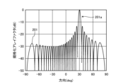
- FIG. 2 is a diagram for explaining the signal level of the transmission radio waves transmitted by the phased array antenna.
- the horizontal axis indicates the direction in which the transmission radio waves are transmitted (deg (degrees)), and the vertical axis indicates the array factor (dB (decibels)) normalized by the maximum value.
- Waveform 201 indicates the signal level of the transmission radio waves transmitted by the phased array antenna 10a shown in FIG. 1.
- phased array antenna 10a is controlled to adjust the phase of each antenna element 12 and transmit the transmission radio waves in a direction of 30°. Therefore, waveform 201 has a main lobe 201a in the direction of 30°.
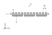
- Fig. 3 is a diagram for explaining a configuration example of the phased array antenna according to the first embodiment.
- the phased array antenna 10 includes a substrate 11, a plurality of antenna elements 12, and a plurality of RFIC chips 14.
- the plurality of phase shifters 13 are omitted.
- the physical length of half the wavelength of the radio waves decreases. For example, when the frequency of the radio waves is 300 GHz (gigahertz), the half wavelength of the radio waves is 0.5. Therefore, when considering a phased array antenna with the same number of antenna elements 12, the area becomes smaller as the frequency increases.
- the phased array antenna 10 usually has an RFIC (Radio-Frequency Integrated Circuits) chip 14 on the side opposite to the side on which the antenna elements 12 are provided. It is difficult to miniaturize the RFIC chip 14 in proportion to the wavelength even if the frequency becomes higher. Therefore, if the elements are arranged according to the size of the RFIC chip 14, the spacing between the antenna elements 12 exceeds ⁇ /2. In the example shown in FIG. 3, the spacing D2 between the antenna elements 12 is ⁇ . Specifically, in the example shown in FIG. 3, 32 antenna elements 12 are arranged one-dimensionally at ⁇ intervals along the X-axis direction, and the phase difference between adjacent antenna elements 12 is controlled to 180°.
- RFIC Radio-Frequency Integrated Circuits
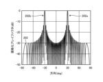
- FIG. 4 is a diagram for explaining the signal level of the transmission radio wave transmitted by the phased array antenna according to the first embodiment.
- the horizontal axis indicates the direction in which the transmission radio wave is transmitted (deg (degrees)), and the vertical axis indicates the array factor (dB (decibels)) normalized by the maximum value.
- a waveform 202 indicates the signal level of the transmission radio wave transmitted by the phased array antenna 10 shown in FIG. 3.
- the phased array antenna 10 is controlled to adjust the phase of each antenna element 12 and transmit the transmission radio wave in a direction of 30°.
- a grating lobe 202b occurs in the direction of -30° in addition to the main lobe 202a in the direction of 30°.
- the present disclosure provides a phased array antenna that has good characteristics even when the spacing between antenna elements 12 of the phased array antenna 10 exceeds ⁇ /2.
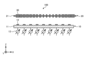
- FIG. 5 is a diagram showing a configuration example of the antenna device according to the first embodiment.
- the antenna device 100 includes a phased array antenna 10 and a radio wave control plate 20.
- the radio wave control plate 20 is provided in the transmission direction of the radio waves transmitted by the phased array antenna 10.
- the radio wave control plate 20 is configured to refract the radio waves transmitted by the phased array antenna 10 in a predetermined direction.
- the radio wave control plate 20 is a type of control unit that refracts the radio waves transmitted from the phased array antenna 10.
- the radio wave control plate 20 comprises a substrate 21 and a number of unit structures 30.
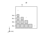
- FIG. 6 is a diagram showing an example of the configuration of the radio wave control plate according to the first embodiment.
- the radio wave control plate 20 is a plate-shaped member configured to transmit the radio waves transmitted by the phased array antenna 10 and enable the formation of a specific beam. For example, when the radio wave control plate 20 receives the radio waves transmitted by the phased array antenna 10, it refracts the transmitted radio waves at a predetermined angle.
- the radio wave control plate 20 can be configured, for example, with a metasurface having an array of resonators that change the phase of the incident wave.
- the radio wave control plate 20 may include, for example, a substrate 21, a unit structure 30a, a unit structure 30b, a unit structure 30c, and a unit structure 30d.
- unit structures 30 When there is no need to distinguish between unit structures 30a to 30d, they are collectively referred to as unit structures 30.
- the unit structure 30a, the unit structure 30b, the unit structure 30c, and the unit structure 30d may be formed on the substrate 2.
- the substrate 21 may be, for example, a dielectric substrate formed of a dielectric material.
- the substrate 21 may have, for example, a rectangular shape, but is not limited to this.
- the unit structure 30a, the unit structure 30b, the unit structure 30c, and the unit structure 30d may be arranged two-dimensionally.
- a plurality of unit structures 30a are arranged along the X-axis direction on one level.
- a plurality of unit structures 30b are arranged along the X-axis direction, for example.
- a plurality of unit structures 30c are arranged along the X-axis direction, for example.
- a plurality of unit structures 30d are arranged along the X-axis direction, for example.
- the unit structures 30a, 30b, 30c, and 30d are arranged periodically along the Y-axis direction.
- Unit structure 30a, unit structure 30b, unit structure 30c, and unit structure 30d each have a different size.
- unit structure 30a is the largest, followed by unit structure 30b, unit structure 30c, and unit structure 30d in order of size.
- radio wave control plate 20 has a structure in which multiple unit structures 30 of different sizes are periodically arranged.
- the unit structures 30a to 30d each have a different amount of phase change when radio waves pass through them. That is, the unit structures 30a to 30d are periodically arranged so that there is a gradient in the amount of phase change.
- the unit structures 30a to 30d each have a rectangular shape, but are not limited to this. By changing the size and shape of the unit structures 30a to 30d, the amount of phase change of the passing radio waves can be adjusted. In other words, the radio wave control plate 20 can refract the transmitted radio waves from the phased array antenna 10 in a desired direction or form a desired beam shape by changing the arrangement method and size of the unit structures 30a to 30d.
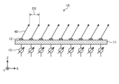
- FIG. 7 is a diagram for explaining the transmission direction of the transmission radio waves of a phased array antenna according to a comparative example.
- the phased array antenna 10 transmits transmission radio waves 40 from each antenna element 12, for example, in a direction of 30°.
- the spacing between the antenna elements 12 is ⁇
- the spacing D3 of the transmission radio waves 40 is ⁇ .
- grating lobes occur in the transmission radio waves 40 in the direction of -30°.
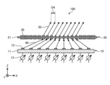
- the antenna device 100 is configured to refract the transmission radio wave 40 transmitted by the phased array antenna 10, in which the spacing between the antenna elements 12 is ⁇ , and emit the transmitted wave 50 in a direction of 30°.
- the phased array antenna 10 transmits the transmission radio wave 40 to the radio wave control plate 20 based on the phase gradient of the unit structure 30 of the radio wave control plate 20 so that the radio wave control plate 20 emits the transmitted wave 50 in a direction of 30°.
- the phased array antenna 10 controls the direction in which the transmission radio wave 40 is transmitted according to the phase gradient of the unit structure 30 of the radio wave control plate 20. In the example shown in FIG.
- the spacing D4 of the transmitted wave 50 is ⁇ /2. That is, by including the radio wave control plate 20, the antenna device 100 can transmit transmission radio waves in which the spacing between the antenna elements 12 of the phased array antenna 10 can be considered to be ⁇ /2. As a result, even if the spacing between the antenna elements 12 is ⁇ , grating lobes can be suppressed.
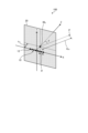
- the phased array antenna 10 includes a first antenna element 121 , a second antenna element 122 , a third antenna element 123 , a fourth antenna element 124, a fifth antenna element 125 , a sixth antenna element 126 , a seventh antenna element 127 , and an eighth antenna element 128.
- the antenna elements 12 are arranged one-dimensionally at equal intervals along the X-axis direction.
- the interval D between the antenna elements 12 is ⁇ .
- the Y coordinate of the center of the phased array antenna 10 is set to 0.
- the radio wave control plate 20 is disposed at a position zm from the phased array antenna 10 in the transmission direction of the transmitted radio wave from the phased array antenna 10. zm is 10 ⁇ .
- the X and Y coordinates of the radio wave control plate 20 are set to 0.
- a reception point P indicates a reception position of a radio wave transmitted by the antenna device 100.
- the reception point P is set on a circle C at a distance d2,k from the origin in the ZX plane, where d2,k is 100 m.
- the calculation conditions for the characteristics of the antenna device 100 will be described.
- the phased array antenna 10 is port 1.
- the receiving point P is port 2.
- the angle between the line connecting the origin and the receiving point P and the Z axis is ⁇ .
- the transmission coefficient S21( ⁇ ) of the radio wave control plate 20 at this time is calculated using the following formula (1), and the radiation pattern is calculated by changing ⁇ .
- s i,k represents the transmission coefficient of a path that passes from the i-th antenna element 12 of the phased array antenna 10 through the k-th unit structure 30 of the radio wave control plate 20 to the reception point P.
- s i,k is calculated by the following formula (2).
- FIG. 11 is a diagram for explaining the conditions for calculating the transmission coefficient of the radio wave control plate according to the first embodiment.
- the transmission point P1 indicates the position of the antenna element 12 that transmits the transmission radio wave.
- the reception point P2 indicates the reception position of the transmission wave emitted from the radio wave control plate 20.
- the unit structure 30 is a square with one side of ⁇ A.
- A is the area of the unit structure 30.
- ⁇ i,k is the angle between the direction of the i-th antenna element 12 as seen from the k-th unit structure 30 k and the Z axis.
- ⁇ 2,k is the angle between the direction of the reception point P as seen from the k-th unit structure 30 and the Z axis.
- d i,k is the distance between the k-th unit structure 30 k and the i-th antenna element 12 i .
- d 2,k is the distance between the k-th unit structure 30 k and the reception point P.
- ⁇ k indicates the phase change of the k-th unit structure.
- ⁇ is the wavelength of the transmission radio wave transmitted by the phased array antenna 10.
- FIG. 12 is a diagram for explaining a simulation condition of an antenna device according to a first comparative example of the first embodiment.
- Fig. 13 is a diagram showing a calculation result of
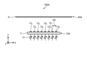
- the antenna device 100A includes a phased array antenna 10A and a radio wave control plate 20A.
- the phased array antenna 10A includes a substrate 11, a first antenna element 121 to an eighth antenna element 128 , and a plurality of phase shifters 13.
- the first antenna element 121 to the eighth antenna element 128 are arranged at equal intervals along the X-axis direction.
- the interval D5 between adjacent antenna elements 12 among the first antenna element 121 to the eighth antenna element 128 is ⁇ /2.
- the phase difference between each antenna element 12 is ⁇ 90°.
- the plurality of phase shifters 13 are provided for each of the first antenna element 121 to the eighth antenna element 128 .
- the transmission phases of the unit structures 30 arranged on the radio wave control plate 20A are all equal. Therefore, although the unit structures 30 are actually arranged on the radio wave control plate 20A, they are omitted in FIG. 12.
- Waveform 211 indicates the signal level of the transmission radio wave transmitted by antenna device 100A shown in FIG. 12.
- antenna device 100A is controlled to adjust the phase of each antenna element 12 and transmit the transmission radio wave in a direction of 30°.
- Fig. 14 is a diagram for explaining the simulation conditions of the antenna device according to the second comparative example of the first embodiment.
- Fig. 15 is a diagram showing a simulation result of the transmission wave of the antenna device according to the second comparative example of the first embodiment.
- the antenna device 100B includes a phased array antenna 10B and a radio wave control plate 20B.
- the phased array antenna 10B differs from the phased array antenna 10A shown in Fig. 12 in that the interval D6 between adjacent antenna elements 12 from the first antenna element 121 to the eighth antenna element 128 is ⁇ . Also, in the phased array antenna 10B, the phase difference between each antenna element 12 is -180°.
- the configuration of the radio wave control plate 20B is the same as that of the radio wave control plate 20A shown in Fig. 12.
- Waveform 212 indicates the signal level of the transmission radio wave transmitted by antenna device 100B shown in FIG. 14.
- antenna device 100B is controlled to adjust the phase of each antenna element 12 and transmit the transmission radio wave in a 30° direction.
- waveform 212 there is a main lobe 212a in the 30° direction, and a grating lobe 212b in the -30° direction.
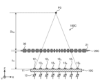
- Fig. 16 is a diagram for explaining the simulation conditions of the antenna device according to the first embodiment.
- the antenna device 100C includes a phased array antenna 10C and a radio wave control plate 20C.
- the configuration of the phased array antenna 10C is the same as that of the phased array antenna 10B shown in FIG. 14.
- the radio wave control plate 20C comprises a substrate 21 and a plurality of unit structures 30.
- the plurality of unit structures 30 have a distribution of transmission phases that diffuse the radio waves transmitted from the phased array antenna 10C.
- the phase distribution of the transmission phases of the plurality of unit structures 30 is set according to the wavelength of the transmitted radio waves.
- FIG. 17 is a diagram for explaining a method for setting the phase distribution of the unit structures of the radio wave control plate according to the first embodiment.
- the distance between the phased array antenna 10C and the radio wave control plate 20C is zm .
- the position of the focal point P3 is set at a position 2zm away from the radio wave control plate 20C.
- zm is, for example, 10m.
- the phase distribution of each unit structure 30 is set according to the following formula (3).
- Equation (3) is an equation for setting a phase distribution in which the focal point of the unit structure 30 as a concave lens is ⁇ 2z m .
- the radio wave control plate 20C diffuses radio waves from a distant place toward the phased array antenna 10C, and conversely, it is possible to control the radio waves from the phased array antenna 10C to form a beam in a predetermined direction.
- the presence of the radio wave control plate 20C allows an antenna device including the phased array antenna 10C and the radio wave control plate 20C to operate equivalently in the same manner as a phased array antenna with a narrow spacing.
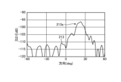
- Waveform 213 indicates the signal level of the transmission radio waves transmitted by the antenna device 100C shown in FIG. 17.
- the antenna device 100C is controlled to adjust the phase of each antenna element 12 and transmit the transmission radio waves in a 30° direction.
- the antenna device 100C can suppress the grating lobes 212b that were generated in FIG. 15.
- the first embodiment combines a phased array antenna with a radio wave control plate to suppress grating lobes that occur when the spacing between antenna elements of a phased array antenna is equal to or greater than half the wavelength of the transmitted radio wave.
- the antenna device 100 has been described as including a radio wave control plate 20 that refracts the transmission radio wave transmitted by the phased array antenna 10, but the present disclosure is not limited thereto.
- a dielectric dielectric lens
- a dielectric plate having a dielectric constant distribution dielectric constant near the center is lower than the periphery.
- the phased array antenna 10C and the antenna device including the dielectric lens can operate in the same manner as a phased array antenna with a narrow spacing equivalently, as in the first embodiment.
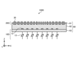
- Fig. 19 illustrates an example of the configuration of an antenna device according to the second embodiment.
- Fig. 19 is a diagram illustrating an example of the configuration of an antenna device according to the second embodiment.
- the antenna device 100D includes a phased array antenna 10D, a radio wave control plate 20D, and a substrate 60.
- the substrate 60 is, for example, a dielectric substrate.
- the substrate 60 has three regions: a first dielectric layer 61, a second dielectric layer 62, and a third dielectric layer 63.
- the phased array antenna 10D comprises a plurality of antenna elements 12, a plurality of phase shifters 13, and a third dielectric layer 63.
- the third dielectric layer 63 can be regarded as a dielectric substrate on which the plurality of antenna elements 12 are arranged.
- the configuration of the phased array antenna 10D is the same as the configuration of the phased array antenna 10C shown in FIG. 16.
- the radio wave control plate 20D comprises a plurality of unit structures 30 and a first dielectric layer 61.
- the first dielectric layer 61 can be regarded as a dielectric substrate on which the plurality of unit structures 30 are arranged.
- the configuration of the radio wave control plate 20D is the same as that of the radio wave control plate 20C shown in FIG. 16.
- the second dielectric layer 62 is located between the first dielectric layer 61 and the third dielectric layer 63.
- the first dielectric layer 61, the second dielectric layer 62, and the third dielectric layer 63 can be considered to be an integrally formed dielectric substrate.
- the antenna device 100D is configured by integrating the phased array antenna 10D and the radio wave control plate 20D.
- the distance between the phased array antenna 10D and the radio wave control plate 20D is stabilized, so that grating lobes can be appropriately suppressed.
- the antenna device 100 includes a phased array antenna 10 including a plurality of antenna elements 12, and a control unit that is provided in the transmission direction of radio waves transmitted by the phased array antenna 10 and that controls the transmission radio waves so that a predetermined beam pattern is formed by forming the transmission phase to differ depending on the position of incidence of the transmission radio waves, and the plurality of antenna elements 12 are arranged at intervals wider than half the wavelength of the transmission radio waves.
- a control unit in the transmission direction of the transmission radio waves of the phased array antenna 10, it is possible to suppress grating lobes.
- the antenna device 100 according to the second aspect of the present disclosure is the antenna device 100 according to the first aspect, in which the control unit is a radio wave control plate 20 including a plurality of unit structures 30 arranged two-dimensionally, and the plurality of unit structures 30 have a distribution of transmission phases that diffuse the transmitted radio waves. According to the present disclosure, grating lobes can be appropriately suppressed.
- the antenna device 100 according to the third aspect of the present disclosure is the antenna device 100 according to the first or second aspect, in which the distribution of the transmission phase of the multiple unit structures 30 is set according to the wavelength of the transmitted radio wave. According to the present disclosure, grating lobes can be appropriately suppressed.
- control section is a dielectric material having a concave lens shape. According to the present disclosure, grating lobes can be appropriately suppressed.
- the phased array antenna 10 and the control unit are integrally configured.
- the antenna device 100 can be configured as a single device.
- the radio wave control plate 20 is provided in the transmission direction of radio waves transmitted by a phased array antenna 10 including a plurality of antenna elements 12, and includes a plurality of unit structures 30 arranged two-dimensionally, and the phases of the plurality of unit structures 30 have a distribution of transmission phases that diffuse the transmitted radio waves according to the wavelength of the transmitted radio waves. According to the present disclosure, it is possible to suppress grating lobes that occur in the transmitted radio waves of the phased array antenna 10.
Landscapes
- Variable-Direction Aerials And Aerial Arrays (AREA)
Abstract
アンテナ装置は、複数のアンテナ素子を含むフェーズドアレイアンテナと、フェーズドアレイアンテナが送信する送信電波の送信方向に設けられ、送信電波が入射した位置によって透過位相が異なるように形成され、所定のビームパターンが形成されるように送信電波を制御する制御部と、を含む。複数のアンテナ素子は、送信電波の半波長よりも広い間隔で配列されている。
Description
本開示は、アンテナ装置および電波制御板に関する。
特許文献1に記載されているように、複数のサブアレイを有するフェーズドアレイアンテナが知られている。
本開示のアンテナ装置は、複数のアンテナ素子を含むフェーズドアレイアンテナと、前記フェーズドアレイアンテナが送信する送信電波の送信方向に設けられ、前記送信電波が入射した位置によって透過位相が異なるように形成され、所定のビームパターンが形成されるように前記送信電波を制御する制御部と、を含み、複数の前記アンテナ素子は、前記送信電波の半波長よりも広い間隔で配列されている。
本開示の電波制御板は、複数のアンテナ素子を含むフェーズドアレイアンテナが送信する送信電波の送信方向に設けられ、2次元状に配列された複数の単位構造を含み、複数の前記単位構造の位相は、前記送信電波の波長に応じた、前記送信電波を拡散させる透過位相の分布を有する。
以下、添付図面を参照して、本発明に係る実施形態を詳細に説明する。なお、この実施形態により本発明が限定されるものではなく、また、以下の実施形態において、同一の部位には同一の符号を付することにより重複する説明を省略する。
以下の説明においては、XYZ直交座標系を設定し、このXYZ直交座標系を参照しつつ各部の位置関係について説明する。水平面内のX軸と平行な方向をX軸方向とし、X軸と直交する水平面内のY軸と平行な方向をY軸方向とし、水平面と直交するZ軸と平行な方向をZ軸方向とする。また、X軸およびY軸を含む平面を適宜XY平面と称し、X軸およびZ軸を含む平面を適宜XZ平面と称し、Y軸およびZ軸を含む平面を適宜YZ平面と称する。XY平面は、水平面と平行である。XY平面とXZ平面とYZ平面とは直交する。
[概要]
(フェーズドアレイアンテナ)
図1を用いて、フェーズドアレイアンテナの概要について説明する。図1は、フェーズドアレイアンテナの概要を説明するための図である。
(フェーズドアレイアンテナ)
図1を用いて、フェーズドアレイアンテナの概要について説明する。図1は、フェーズドアレイアンテナの概要を説明するための図である。
図1に示すように、フェーズドアレイアンテナ10aは、基板11と、複数のアンテナ素子12と、複数の移相器13と、を含む。
基板11は、例えば、複数のアンテナ素子12が配置される誘電体基板である。
複数のアンテナ素子12は、XY平面において、基板11上に等間隔で1次元または2次元のアレイ状に配置されている。複数のアンテナ素子12は、+Z軸方向の所定の方向に向かって送信電波を送信する。複数のアンテナ素子12は、+Z軸方向の所定の方向から到来する受信電波を受信する。アンテナ素子12間の間隔D1は、アンテナ素子12が送受信する電波の波長をλとするとλ/2である。図1に示す例では、例えば、32個のアンテナ素子12がX軸方向に沿ってλ/2間隔で1次元状に配列されている。
複数の移相器13は、アンテナ素子12ごとに設けられている。複数の移相器13は、それぞれ、対応するアンテナ素子12の位相を制御する。複数の移相器13は、対応するアンテナ素子12の位相を制御することで、送受信する電波の指向性を変化させることができる。図1に示す例では、例えば、隣接するアンテナ素子12の位相差が90°に制御されている。
図2は、フェーズドアレイアンテナが送信する送信電波の信号レベルを説明するための図である。図2は、横軸が送信電波を送信する方向(deg(度))を示し、縦軸が最大値で規格化したアレイファクタ(dB(デシベル))を示す。波形201は、図1に示すフェーズドアレイアンテナ10aが送信する送信電波の信号レベルを示す。図2に示す例では、波形201に示すように、フェーズドアレイアンテナ10aは、各アンテナ素子12の位相を調整し、30°の方向に送信電波を送信するように制御されている。そのため、波形201は、30°の方向にメインローブ201aを有する。
[第1実施形態]
図3を用いて、第1実施形態に係るフェーズドアレイアンテナの構成例について説明する。図3は、第1実施形態に係るフェーズドアレイアンテナの構成例を説明するための図である。
図3を用いて、第1実施形態に係るフェーズドアレイアンテナの構成例について説明する。図3は、第1実施形態に係るフェーズドアレイアンテナの構成例を説明するための図である。
図3に示すように、フェーズドアレイアンテナ10は、基板11と、複数のアンテナ素子12と、複数のRFICチップ14と、を含む。図3においては、複数の移相器13は省略されている。
フェーズドアレイアンテナ10が送受信する電波の周波数が高くなると、電波の半波長の物理的な長さは小さくなる。例えば、電波の周波数が300GHz(ギガヘルツ)である場合には、電波の半波長は0.5となる。そのため、アンテナ素子12の数が同じ数のフェーズドアレイアンテナを考えると、周波数が高くなるほど面積が小さくなる。
フェーズドアレイアンテナ10は、通常、アンテナ素子12が設けられている反対の面にRFIC(Radio-Frequency Integrated Circuits)チップ14を備えている。RFICチップ14は、周波数が高くなっても波長に比例して小型化することは困難である。そのため、RFICチップ14のサイズに合わせて素子を配列すると、アンテナ素子12間の間隔はλ/2を超えてしまう。図3に示す例では、アンテナ素子12間の間隔D2は、λである。具体的には、図3に示す例では、32個のアンテナ素子12がX軸方向に沿ってλ間隔で1次元状に配列され、隣接するアンテナ素子12の位相差が180°に制御されている。
図4は、第1実施形態に係るフェーズドアレイアンテナが送信する送信電波の信号レベルを説明するための図である。図4は、横軸が送信電波を送信する方向(deg(度))を示し、縦軸が最大値で規格化したアレイファクタ(dB(デシベル))を示す。波形202は、図3に示すフェーズドアレイアンテナ10が送信する送信電波の信号レベルを示す。図4に示す例では、波形202に示すように、フェーズドアレイアンテナ10は、各アンテナ素子12の位相を調整し、30°の方向に送信電波を送信するように制御されている。しかしながら、アンテナ素子12間の間隔がλ/2を超えると、30°の方向のメインローブ202aの他に-30°の方向にグレーティングローブ202bが発生してしまう。
そこで、本開示は、フェーズドアレイアンテナ10のアンテナ素子12間の間隔が、λ/2を超える場合であっても、良好な特性を有するフェーズドアレイアンテナを構成する。
[アンテナ装置]
図5を用いて、第1実施形態に係るアンテナ装置の構成例について説明する。図5は、第1実施形態に係るアンテナ装置の構成例を示す図である。
図5を用いて、第1実施形態に係るアンテナ装置の構成例について説明する。図5は、第1実施形態に係るアンテナ装置の構成例を示す図である。
図5に示すように、アンテナ装置100は、フェーズドアレイアンテナ10と、電波制御板20と、を含む。
電波制御板20は、フェーズドアレイアンテナ10が送信する送信電波の送信方向に設けられている。電波制御板20は、フェーズドアレイアンテナ10が送信する送信電波を所定の方向に屈折させるように構成されている。電波制御板20は、フェーズドアレイアンテナ10からの送信電波を屈折させる制御部の一種である。
電波制御板20は、基板21と、複数の単位構造30とを備える。
[電波制御板]
図6を用いて、第1実施形態に係る電波制御板の構成例について説明する。図6は、第1実施形態に係る電波制御板の構成例を示す図である。
図6を用いて、第1実施形態に係る電波制御板の構成例について説明する。図6は、第1実施形態に係る電波制御板の構成例を示す図である。
電波制御板20は、フェーズドアレイアンテナ10が送信した送信電波を透過し、特定のビーム形成を可能にするよう構成された板状の部材である。電波制御板20は、例えば、フェーズドアレイアンテナ10が送信した送信電波を受けると、その送信電波を所定の角度に屈折させるように構成されている。電波制御板20は、例えば、入射波の位相を変化させる共振器を配列したメタサーフェスなどで構成され得る。
図6に示すように、電波制御板20は、例えば、基板21と、単位構造30aと、単位構造30bと、単位構造30cと、単位構造30dとを含み得る。単位構造30aから単位構造30dを区別する必要のない場合には、単位構造30と総称する。
単位構造30aと、単位構造30bと、単位構造30cと、単位構造30dとは、基板2上に形成され得る。基板21は、例えば、誘電体で形成された誘電体基板であり得る。基板21は、例えば、矩形形状を有し得るが、これに限定されない。単位構造30aと、単位構造30bと、単位構造30cと、単位構造30dとは、2次元状に配列され得る。
電波制御板20には、例えば、1つの段には複数の単位構造30aがX軸方向に沿って配列されている。単位構造30aが配置されている段の上の段には、例えば、複数の単位構造30bがX軸方向に沿って配列されている。単位構造30bが配置されている段の上の段には、例えば、複数の単位構造30cがX軸方向に沿って配置されている。単位構造30cが設置されている段の上の段には、例えば、複数の単位構造30dがX軸方向に沿って配列されている。図6に示す例では、単位構造30aと、単位構造30bと、単位構造30cと、単位構造30dとが、Y軸方向に沿って、周期的に配列されている。
単位構造30aと、単位構造30bと、単位構造30cと、単位構造30dとは、それぞれ、サイズが異なる。図6に示す例では、単位構造30aのサイズが最も大きく、単位構造30b、単位構造30c、単位構造30dの順にサイズが小さい。すなわち、電波制御板20は、サイズの異なる複数の単位構造30が周期的に配列された構造を有する。
単位構造30aから単位構造30dは、それぞれ、電波が通過する際の位相変化量が異なる。すなわち、単位構造30aから単位構造30dは、位相変化量に勾配を持つように周期的に配列されている。単位構造30aから単位構造30dは、それぞれ矩形形状を有しているが、これに限定されない。単位構造30aから単位構造30dの大きさおよび形状を変化させることで、透過する電波の位相変化量を調整することができる。言い換えれば、電波制御板20は、単位構造30aから単位構造30dの配列方法および大きさなどを変更することで、フェーズドアレイアンテナ10からの送信電波を所望の方向に屈折させたり所望のビーム形状を形成することができる。
図7は、比較例に係るフェーズドアレイアンテナの送信電波の送信方向を説明するための図である。図7に示すように、フェーズドアレイアンテナ10は、各アンテナ素子12から、例えば、30°の方向に送信電波40を送信する。アンテナ素子12間の間隔がλである場合には、送信電波40の間隔D3はλである。この場合、上述したように、送信電波40には、-30°の方向には、グレーティングローブが発生してしまう。
図8は、第1実施形態に係るアンテナ装置の送信電波の送信方向を説明するための図である。アンテナ装置100は、アンテナ素子12間の間隔がλであるフェーズドアレイアンテナ10が送信した送信電波40を屈折させて、透過波50を30°の方向に出射するように構成されている。この場合、フェーズドアレイアンテナ10は、電波制御板20の単位構造30の位相勾配に基づいて、電波制御板20が透過波50を30°の方向に出射するように、電波制御板20に対して送信電波40を送信する。言い換えれば、フェーズドアレイアンテナ10は、電波制御板20の単位構造30の位相勾配に応じて、送信電波40を送信する方向を制御する。図8に示す例では、透過波50の間隔D4はλ/2である。すなわち、アンテナ装置100は、電波制御板20を備えることで、フェーズドアレイアンテナ10のアンテナ素子12の間隔がλ/2とみなせる、送信電波を送信することができる。これにより、アンテナ素子12の間隔がλであってもグレーティングローブを抑圧することができる。
[シミュレーション]
(シミュレーション条件)
第1実施形態では、アンテナ装置100についてシミュレーションを実施して、特性を確認した。図9と、図10は、第1実施形態に係るアンテナ装置のシミュレーション条件を説明するための図である。
(シミュレーション条件)
第1実施形態では、アンテナ装置100についてシミュレーションを実施して、特性を確認した。図9と、図10は、第1実施形態に係るアンテナ装置のシミュレーション条件を説明するための図である。
図9と、図10とに示す例では、フェーズドアレイアンテナ10は、第1アンテナ素子121と、第2アンテナ素子122と、第3アンテナ素子123と、第4アンテナ素子124と、第5アンテナ素子125と、第6アンテナ素子126と、第7アンテナ素子127と、第8アンテナ素子128と、を備える。第1アンテナ素子121から第8アンテナ素子128を区別する必要のない場合には、アンテナ素子12と総称する。すなわち、フェーズドアレイアンテナ10は、アンテナ素子12をM=8個備える(Mはフェーズドアレイアンテナの素子数)。各アンテナ素子12は、X軸方向に沿って等間隔に1次元状に配列されている。アンテナ素子12間の間隔Dはλである。フェーズドアレイアンテナ10の中心のY座標を0としている。
電波制御板20は、フェーズドアレイアンテナ10の送信電波の送信方向において、フェーズドアレイアンテナ10からzmの位置に設けられている。zmは10λである。電波制御板20には、N=32×32=1024個の単位構造30が2次元状に等間隔で配列されている(Nはメタサーフェスの素子数)。単位構造30間の間隔はλ/2である。電波制御板20のX座標およびY座標を0としている。
受信点Pは、図10に示すように、アンテナ装置100が送信する送信電波の受信位置を示す。受信点Pは、ZX平面において、原点から距離d2,kの円C上に設定される。d2,kは100mである。
(計算条件)
アンテナ装置100の特性の計算条件について説明する。フェーズドアレイアンテナ10をポート1とする。受信点Pをポート2とする。原点と受信点Pを結ぶ直線と、Z軸とのなす角度をθとする。このときの、電波制御板20の透過係数S21(θ)を以下の式(1)で計算し、θを変化させて放射パターンを計算する。
アンテナ装置100の特性の計算条件について説明する。フェーズドアレイアンテナ10をポート1とする。受信点Pをポート2とする。原点と受信点Pを結ぶ直線と、Z軸とのなす角度をθとする。このときの、電波制御板20の透過係数S21(θ)を以下の式(1)で計算し、θを変化させて放射パターンを計算する。

ここで、si,kは、フェーズドアレイアンテナ10のi番目のアンテナ素子12から電波制御板20のk番目の単位構造30を通過して受信点Pに到達する経路の透過係数を表す。si,kを以下の式(2)で算出する。

図11は、第1実施形態に係る電波制御板の透過係数を算出する条件を説明するための図である。送信点P1は、送信電波を送信するアンテナ素子12の位置を示す。受信点P2は、電波制御板20から出射する透過波の受信位置を示す。単位構造30は、1辺が√Aの正方形としている。ここで、Aは単位構造30の面積である。φi,kはk番目の単位構造30kからみたi番目のアンテナ素子12方向とZ軸とのなす角度である。φ2,kは、k番目の単位構造30からみた受信点Pの方向とZ軸とのなす角度である。di,kは、k番目の単位構造30kとi番目のアンテナ素子12iとの間の距離である。d2,kは、k番目の単位構造30kと受信点Pとの間の距離である。Φkは、k番目の単位構造の位相変化を示す。λはフェーズドアレイアンテナ10が送信する送信電波の波長である。
(計算結果)
<第1比較例>
第1比較例に係るアンテナ装置の送信電波のシミュレーション結果について説明する。図12は、第1実施形態の第1比較例に係るアンテナ装置のシミュレーション条件を説明するための図である。図13は、第1実施形態の第1比較例に係るアンテナ装置の|S21|の計算結果を示す図である。
<第1比較例>
第1比較例に係るアンテナ装置の送信電波のシミュレーション結果について説明する。図12は、第1実施形態の第1比較例に係るアンテナ装置のシミュレーション条件を説明するための図である。図13は、第1実施形態の第1比較例に係るアンテナ装置の|S21|の計算結果を示す図である。
図12に示すように、アンテナ装置100Aは、フェーズドアレイアンテナ10Aと、電波制御板20Aと、を含む。
フェーズドアレイアンテナ10Aは、基板11と、第1アンテナ素子121から第8アンテナ素子128と、複数の移相器13と、を含む。第1アンテナ素子121から第8アンテナ素子128は、X軸方向に沿って等間隔に配列されている。第1アンテナ素子121から第8アンテナ素子128の隣接するアンテナ素子12間の間隔D5はλ/2である。各アンテナ素子12間の位相差は、-90°である。複数の移相器13は、第1アンテナ素子121から第8アンテナ素子128ごとに設けられている。
電波制御板20Aには、N=32×32=1024個の単位構造30が2次元状に等間隔で配列されている。第1比較例では、電波制御板20Aに配置されている単位構造30の透過位相は全て等しい。そのため、電波制御板20Aには、実際には単位構造30が配列されているが、図12では省略して示している。
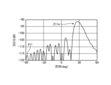
図13は、横軸が送信電波を送信する方向(deg)を示し、縦軸が式(1)で計算したS21の振幅(dB)を示す。波形211は、図12に示すアンテナ装置100Aが送信する送信電波の信号レベルを示す。図13に示す例では、波形211に示すように、アンテナ装置100Aは、各アンテナ素子12の位相を調整し、30°の方向に送信電波を送信するように制御されている。波形211が示すように、30°方向にメインローブ211aがあるが、グレーティングローブは発生していない。
<第2比較例>
第2比較例に係るアンテナ装置の送信電波のシミュレーション結果について説明する。図14は、第1実施形態の第2比較例に係るアンテナ装置のシミュレーション条件を説明するための図である。図15は、第1実施形態の第2比較例に係るアンテナ装置の送信電波のシミュレーション結果を示す図である。
第2比較例に係るアンテナ装置の送信電波のシミュレーション結果について説明する。図14は、第1実施形態の第2比較例に係るアンテナ装置のシミュレーション条件を説明するための図である。図15は、第1実施形態の第2比較例に係るアンテナ装置の送信電波のシミュレーション結果を示す図である。
図14に示すように、アンテナ装置100Bは、フェーズドアレイアンテナ10Bと、電波制御板20Bと、を含む。
フェーズドアレイアンテナ10Bは、第1アンテナ素子121から第8アンテナ素子128の隣接するアンテナ素子12間の間隔D6がλである点で、図12に示すフェーズドアレイアンテナ10Aと異なる。また、フェーズドアレイアンテナ10Bにおいては、各アンテナ素子12間の位相差は、-180°である。電波制御板20Bの構成は、図12に示す電波制御板20Aと同じである。
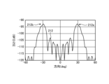
図15は、横軸が送信電波を送信する方向(deg)を示し、縦軸が式(1)で計算したS21の振幅(dB)を示す。波形212は、図14に示すアンテナ装置100Bが送信する送信電波の信号レベルを示す。図15に示す例では、波形212に示すように、アンテナ装置100Bは、各アンテナ素子12の位相を調整し、30°の方向に送信電波を送信するように制御されている。波形212が示すように、30°方向にメインローブ212aがあり、-30°の方向にグレーティングローブ212bがある。
<第1実施形態>
第1実施形態に係るアンテナ装置の送信電波のシミュレーション結果について説明する。図16は、第1実施形態に係るアンテナ装置のシミュレーション条件を説明するための図である。
第1実施形態に係るアンテナ装置の送信電波のシミュレーション結果について説明する。図16は、第1実施形態に係るアンテナ装置のシミュレーション条件を説明するための図である。
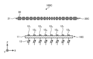
図16に示すように、アンテナ装置100Cは、フェーズドアレイアンテナ10Cと、電波制御板20Cと、を含む。フェーズドアレイアンテナ10Cの構成は、図14に示すフェーズドアレイアンテナ10Bと同じである。
電波制御板20Cは、基板21と、複数の単位構造30と、を備える。電波制御板20Cにおいて、複数の単位構造30は、フェーズドアレイアンテナ10Cからの送信電波を拡散させる透過位相の分布を有する。具体的には、複数の単位構造30の透過位相の位相分布は、送信電波の波長に応じて設定されている。
図17は、第1実施形態に係る電波制御板の単位構造の位相分布を設定する方法を説明するための図である。フェーズドアレイアンテナ10Cと、電波制御板20Cとの間の距離をzmとする。このとき、焦点P3の位置を電波制御板20Cから2zmの位置に設定する。zmは、例えば、10mである。この場合、各単位構造30の位相分布は、以下の式(3)に従って設定されている。

ここで、xmは、単位構造30のX座標である。ymは、単位構造30のY座標である。式(3)は、凹レンズとしての焦点が-2zmとなる位相分布を設定するための式である。このような位相分布により、電波制御板20Cは、遠方からの電波をフェーズドアレイアンテナ10Cに向けて拡散することになり、逆にフェーズドアレイアンテナ10Cからの電波を所定の方向にビームが形成されるように制御することができる。すなわち、電波制御板20Cが存在することにより、フェーズドアレイアンテナ10Cと、電波制御板20Cとを備えたアンテナ装置は、等価的に間隔の狭いフェーズドアレイアンテナと同様の動作をさせることができる。
図18は、第1実施形態に係るアンテナ装置の送信電波のシミュレーション結果を示す図である。図18は、横軸が送信電波を送信する方向(deg)を示し、縦軸が式(1)で計算したS21の振幅(dB)を示す。波形213は、図17に示すアンテナ装置100Cが送信する送信電波の信号レベルを示す。図17に示す例では、波形213に示すように、アンテナ装置100Cは、各アンテナ素子12の位相を調整し、30°の方向に送信電波を送信するように制御されている。波形213が示すように、30°方向にメインローブ213aがあるが、グレーティングローブは発生していない。すなわち、アンテナ装置100Cは、図15で発生していた、グレーティングローブ212bを抑圧することができる。
上述のとおり、第1実施形態は、フェーズドアレイアンテナと、電波制御板とを組み合わせることで、フェーズドアレイアンテナのアンテナ素子の間隔が送信電波の半波長以上になったときに発生するグレーティングローブを抑圧することができる。
[第1実施形態の変形例]
第1実施形態の変形例について説明する。図5に示すように、第1実施形態では、アンテナ装置100は、フェーズドアレイアンテナ10が送信する送信電波を屈折させる電波制御板20を含むものとして説明したが、本開示はこれに限定されない。本開示は、電波制御板の代わりに、周囲に比べて中心付近の厚さが薄い凹型のレンズ形状を有する誘電体(誘電体レンズ)であってもよい。または誘電率に分布(周囲に比べて中心付近の誘電率が低い)を持たせた誘電体板であってもよい。第1実施形態の変形例では、このような凹型のレンズ形状の誘電体により、フェーズドアレイアンテナ10Cと、当該誘電体レンズとを備えたアンテナ装置は、上記第1実施形態と同様に、等価的に間隔の狭いフェーズドアレイアンテナと同様の動作をさせることができる。
第1実施形態の変形例について説明する。図5に示すように、第1実施形態では、アンテナ装置100は、フェーズドアレイアンテナ10が送信する送信電波を屈折させる電波制御板20を含むものとして説明したが、本開示はこれに限定されない。本開示は、電波制御板の代わりに、周囲に比べて中心付近の厚さが薄い凹型のレンズ形状を有する誘電体(誘電体レンズ)であってもよい。または誘電率に分布(周囲に比べて中心付近の誘電率が低い)を持たせた誘電体板であってもよい。第1実施形態の変形例では、このような凹型のレンズ形状の誘電体により、フェーズドアレイアンテナ10Cと、当該誘電体レンズとを備えたアンテナ装置は、上記第1実施形態と同様に、等価的に間隔の狭いフェーズドアレイアンテナと同様の動作をさせることができる。
これにより、第1実施形態の変形例では、フェーズドアレイアンテナのアンテナ素子の間隔が送信電波の半波長以上になったときに発生するグレーティングローブを抑制することができる。
[第2実施形態]
図19は、第2実施形態に係るアンテナ装置の構成例について説明する。図19は、第2実施形態に係るアンテナ装置の構成例を示す図である。
図19は、第2実施形態に係るアンテナ装置の構成例について説明する。図19は、第2実施形態に係るアンテナ装置の構成例を示す図である。
図19に示すように、アンテナ装置100Dは、フェーズドアレイアンテナ10Dと、電波制御板20Dと、基板60と、を含む。
基板60は、例えば、誘電体基板である。基板60は、第1誘電体層61と、第2誘電体層62と、第3誘電体層63との3つの領域を有する。
フェーズドアレイアンテナ10Dは、複数のアンテナ素子12と、複数の移相器13と、第3誘電体層63と、を備える。第3誘電体層63は、複数のアンテナ素子12が配置される誘電体基板とみなせる。フェーズドアレイアンテナ10Dの構成は、図16に示すフェーズドアレイアンテナ10Cの構成と同じである。
電波制御板20Dは、複数の単位構造30と、第1誘電体層61と、を備える。第1誘電体層61は、複数の単位構造30が配列される誘電体基板とみなせる。電波制御板20Dの構成は、図16に示す電波制御板20Cと同じである。
第2誘電体層62は、第1誘電体層61と、第3誘電体層63との間に位置する。第1誘電体層61と、第2誘電体層62と、第3誘電体層63とは、一体に構成された誘電体基板とみなせる。
すなわち、アンテナ装置100Dは、フェーズドアレイアンテナ10Dと、電波制御板20Dとが一体に構成されている。フェーズドアレイアンテナ10Dと、電波制御板20Dとを一体に構成することで、フェーズドアレイアンテナ10Dと、電波制御板20Dとの間の距離が安定するので、グレーティングローブを適切に抑圧することができる。
本開示の第1態様に係るアンテナ装置100は、複数のアンテナ素子12を含むフェーズドアレイアンテナ10と、フェーズドアレイアンテナ10が送信する送信電波の送信方向に設けられ、送信電波が入射した位置によって透過位相が異なるように形成され、所定のビームパターンが形成されるように送信電波を制御する制御部と、を含み、複数のアンテナ素子12は、送信電波の半波長よりも広い間隔で配列されている。本開示によれば、フェーズドアレイアンテナ10の送信電波の送信方向に制御部を設けることで、グレーティングローブを抑圧することができる。
本開示の第2態様に係るアンテナ装置100は、第1態様に係るアンテナ装置100であって、制御部は、2次元状に配列された複数の単位構造30を含む電波制御板20であり、複数の単位構造30は、送信電波を拡散させる透過位相の分布を有する。本開示によれば、グレーティングローブを適切に抑圧することができる。
本開示の第3態様に係るアンテナ装置100は、第1態様または第2態様に係るアンテナ装置100であって、複数の単位構造30の透過位相の分布は、送信電波の波長に応じて設定されている。本開示によれば、グレーティングローブを適切に抑圧することができる。
本開示の第4態様に係るアンテナ装置100は、制御部は、凹型のレンズ形状を有する誘電体である。本開示によれば、グレーティングローブを適切に抑圧することができる。
本開示の第5態様に係るアンテナ装置100は、フェーズドアレイアンテナ10と、制御部とは、一体に構成されている。本開示によれば、アンテナ装置100を、1つの装置として構成することができる。
本開示の第6態様に係る電波制御板20は、複数のアンテナ素子12を含むフェーズドアレイアンテナ10が送信する送信電波の送信方向に設けられ、2次元状に配列された複数の単位構造30を含み、複数の単位構造30の位相は、送信電波の波長に応じた、送信電波を拡散させる透過位相の分布を有する。本開示によれば、フェーズドアレイアンテナ10の送信電波に生じる、グレーティングローブを抑圧することができる。
以上、本開示の実施形態を説明したが、これら実施形態の内容により本開示が限定されるものではない。また、前述した構成要素には、当業者が容易に想定できるもの、実質的に同一のもの、いわゆる均等の範囲のものが含まれる。さらに、前述した構成要素は適宜組み合わせることが可能である。さらに、前述した実施形態の要旨を逸脱しない範囲で構成要素の種々の省略、置換又は変更を行うことができる。
10,10a,10A,10B,10C,10D フェーズドアレイアンテナ
11,21,60 基板
12 アンテナ素子
13 移相器
20,20A,20B,20C,20D 電波制御板
30 単位構造
40 送信電波
50 透過波
61 第1誘電体層
62 第2誘電体層
63 第3誘電体層
100,100A,100B,100C,100D アンテナ装置
11,21,60 基板
12 アンテナ素子
13 移相器
20,20A,20B,20C,20D 電波制御板
30 単位構造
40 送信電波
50 透過波
61 第1誘電体層
62 第2誘電体層
63 第3誘電体層
100,100A,100B,100C,100D アンテナ装置
Claims (6)
- 複数のアンテナ素子を含むフェーズドアレイアンテナと、
前記フェーズドアレイアンテナが送信する送信電波の送信方向に設けられ、前記送信電波が入射した位置によって透過位相が異なるように形成され、所定のビームパターンが形成されるように前記送信電波を制御する制御部と、を含み、
複数の前記アンテナ素子は、前記送信電波の半波長よりも広い間隔で配列されている、
アンテナ装置。 - 前記制御部は、2次元状に配列された複数の単位構造を含む電波制御板であり、
複数の前記単位構造は、前記送信電波を拡散させる透過位相の分布を有する、
請求項1に記載のアンテナ装置。 - 複数の単位構造の透過位相の分布は、前記送信電波の波長に応じて設定されている、
請求項2に記載のアンテナ装置。 - 前記制御部は、凹型のレンズ形状を有する誘電体である、
請求項1に記載のアンテナ装置。 - 前記フェーズドアレイアンテナと、前記制御部とは、一体に構成されている、
請求項1に記載のアンテナ装置。 - 複数のアンテナ素子を含むフェーズドアレイアンテナが送信する送信電波の送信方向に設けられ、2次元状に配列された複数の単位構造を含み、
複数の前記単位構造の位相は、前記送信電波の波長に応じた、前記送信電波を拡散させる透過位相の分布を有する、
電波制御板。
Priority Applications (2)
| Application Number | Priority Date | Filing Date | Title |
|---|---|---|---|
| JP2023559000A JP7634715B1 (ja) | 2023-06-16 | 2023-06-16 | アンテナ装置および電波制御板 |
| PCT/JP2023/022478 WO2024257350A1 (ja) | 2023-06-16 | 2023-06-16 | アンテナ装置および電波制御板 |
Applications Claiming Priority (1)
| Application Number | Priority Date | Filing Date | Title |
|---|---|---|---|
| PCT/JP2023/022478 WO2024257350A1 (ja) | 2023-06-16 | 2023-06-16 | アンテナ装置および電波制御板 |
Publications (1)
| Publication Number | Publication Date |
|---|---|
| WO2024257350A1 true WO2024257350A1 (ja) | 2024-12-19 |
Family
ID=93851638
Family Applications (1)
| Application Number | Title | Priority Date | Filing Date |
|---|---|---|---|
| PCT/JP2023/022478 Ceased WO2024257350A1 (ja) | 2023-06-16 | 2023-06-16 | アンテナ装置および電波制御板 |
Country Status (2)
| Country | Link |
|---|---|
| JP (1) | JP7634715B1 (ja) |
| WO (1) | WO2024257350A1 (ja) |
Citations (5)
| Publication number | Priority date | Publication date | Assignee | Title |
|---|---|---|---|---|
| JPH09162638A (ja) * | 1995-12-08 | 1997-06-20 | Dx Antenna Co Ltd | 平面アレーアンテナ |
| JPH1065439A (ja) * | 1996-08-22 | 1998-03-06 | Mitsubishi Electric Corp | アレーアンテナ装置 |
| JP2018157541A (ja) * | 2017-03-17 | 2018-10-04 | アイソトロピック システムズ リミテッドIsotropic Systems Ltd. | レンズアンテナシステム |
| JP2021516005A (ja) * | 2018-02-22 | 2021-06-24 | ユニバーシティ オブ マサチューセッツ | アンテナハードウェア及び制御 |
| JP2023509575A (ja) * | 2020-01-08 | 2023-03-09 | メタウェーブ コーポレーション | 2次元ビームスキャニングを有するリフレクトアレイアンテナ |
Family Cites Families (1)
| Publication number | Priority date | Publication date | Assignee | Title |
|---|---|---|---|---|
| CN111834756B (zh) * | 2019-04-15 | 2021-10-01 | 华为技术有限公司 | 天线阵列及无线设备 |
-
2023
- 2023-06-16 WO PCT/JP2023/022478 patent/WO2024257350A1/ja not_active Ceased
- 2023-06-16 JP JP2023559000A patent/JP7634715B1/ja active Active
Patent Citations (5)
| Publication number | Priority date | Publication date | Assignee | Title |
|---|---|---|---|---|
| JPH09162638A (ja) * | 1995-12-08 | 1997-06-20 | Dx Antenna Co Ltd | 平面アレーアンテナ |
| JPH1065439A (ja) * | 1996-08-22 | 1998-03-06 | Mitsubishi Electric Corp | アレーアンテナ装置 |
| JP2018157541A (ja) * | 2017-03-17 | 2018-10-04 | アイソトロピック システムズ リミテッドIsotropic Systems Ltd. | レンズアンテナシステム |
| JP2021516005A (ja) * | 2018-02-22 | 2021-06-24 | ユニバーシティ オブ マサチューセッツ | アンテナハードウェア及び制御 |
| JP2023509575A (ja) * | 2020-01-08 | 2023-03-09 | メタウェーブ コーポレーション | 2次元ビームスキャニングを有するリフレクトアレイアンテナ |
Also Published As
| Publication number | Publication date |
|---|---|
| JP7634715B1 (ja) | 2025-02-21 |
| JPWO2024257350A1 (ja) | 2024-12-19 |
Similar Documents
| Publication | Publication Date | Title |
|---|---|---|
| JP6798657B1 (ja) | アンテナモジュールおよびそれを搭載した通信装置 | |
| Rupakula et al. | Limited scan-angle phased arrays using randomly grouped subarrays and reduced number of phase shifters | |
| JP7224174B2 (ja) | 電子装置およびレーダー制御方法 | |
| JP7156518B2 (ja) | サブアレイアンテナ、アレイアンテナ、アンテナモジュール、および通信装置 | |
| EP3783738B1 (en) | Wideband beam broadening for phased array antenna systems | |
| CA2793316C (en) | An rf feed network for modular active aperture electronically steered arrays | |
| US9972915B2 (en) | Optimized true-time delay beam-stabilization techniques for instantaneous bandwith enhancement | |
| US9054414B2 (en) | Antenna system for low-earth-orbit satellites | |
| CN114336080A (zh) | 透镜天线系统 | |
| CN112072309B (zh) | 一种步进补偿低成本相控阵天线架构及其设计方法 | |
| US12218435B2 (en) | Multi-beam on receive electronically-steerable antenna | |
| WO2019170541A1 (en) | Extreme scanning focal-plane arrays using a double-reflector concept with uniform array illumination | |
| JP7634715B1 (ja) | アンテナ装置および電波制御板 | |
| US10741917B2 (en) | Power division in antenna systems for millimeter wave applications | |
| Rahimian | Design and Performance of a K U-Band Rotman Lens Beamforming Network for Satellite Systems | |
| US12132255B2 (en) | Multibeam antenna | |
| CN120222040A (zh) | 随机旋转组阵的同心圆环稀布阵圆极化相控阵天线设计方法 | |
| KR102021888B1 (ko) | 모노펄스 시스템을 위한 나선형 능동 위상배열 안테나 | |
| US12119557B2 (en) | Grating lobe cancellation | |
| Ghate et al. | Quasi-optical beamforming approach using vertically oriented dielectric wedges | |
| Laue et al. | Design and analysis of a proof-of-concept checkered-network compressive array | |
| WO2021106003A1 (en) | Metal waveguide connected antenna array | |
| TWI797919B (zh) | 波束成型裝置及波束控制方法 | |
| CN116315676B (zh) | 一种相控阵阵面及阵面优化方法 | |
| JP7457073B2 (ja) | ビーム形成装置およびビーム制御方法 |
Legal Events
| Date | Code | Title | Description |
|---|---|---|---|
| WWE | Wipo information: entry into national phase |
Ref document number: 2023559000 Country of ref document: JP |
|
| 121 | Ep: the epo has been informed by wipo that ep was designated in this application |
Ref document number: 23941649 Country of ref document: EP Kind code of ref document: A1 |
|
| NENP | Non-entry into the national phase |
Ref country code: DE |
|
| 122 | Ep: pct application non-entry in european phase |
Ref document number: 23941649 Country of ref document: EP Kind code of ref document: A1 |