WO2024257350A1 - Dispositif d'antenne et plaque de commande d'onde radio - Google Patents
Dispositif d'antenne et plaque de commande d'onde radio Download PDFInfo
- Publication number
- WO2024257350A1 WO2024257350A1 PCT/JP2023/022478 JP2023022478W WO2024257350A1 WO 2024257350 A1 WO2024257350 A1 WO 2024257350A1 JP 2023022478 W JP2023022478 W JP 2023022478W WO 2024257350 A1 WO2024257350 A1 WO 2024257350A1
- Authority
- WO
- WIPO (PCT)
- Prior art keywords
- antenna
- transmission
- radio wave
- phased array
- array antenna
- Prior art date
- Legal status (The legal status is an assumption and is not a legal conclusion. Google has not performed a legal analysis and makes no representation as to the accuracy of the status listed.)
- Pending
Links
Images


Classifications
-
- H—ELECTRICITY
- H01—ELECTRIC ELEMENTS
- H01Q—ANTENNAS, i.e. RADIO AERIALS
- H01Q19/00—Combinations of primary active antenna elements and units with secondary devices, e.g. with quasi-optical devices, for giving the antenna a desired directional characteristic
- H01Q19/06—Combinations of primary active antenna elements and units with secondary devices, e.g. with quasi-optical devices, for giving the antenna a desired directional characteristic using refracting or diffracting devices, e.g. lens
-
- H—ELECTRICITY
- H01—ELECTRIC ELEMENTS
- H01Q—ANTENNAS, i.e. RADIO AERIALS
- H01Q21/00—Antenna arrays or systems
- H01Q21/06—Arrays of individually energised antenna units similarly polarised and spaced apart
- H01Q21/08—Arrays of individually energised antenna units similarly polarised and spaced apart the units being spaced along or adjacent to a rectilinear path
-
- H—ELECTRICITY
- H01—ELECTRIC ELEMENTS
- H01Q—ANTENNAS, i.e. RADIO AERIALS
- H01Q3/00—Arrangements for changing or varying the orientation or the shape of the directional pattern of the waves radiated from an antenna or antenna system
- H01Q3/44—Arrangements for changing or varying the orientation or the shape of the directional pattern of the waves radiated from an antenna or antenna system varying the electric or magnetic characteristics of reflecting, refracting, or diffracting devices associated with the radiating element
- H01Q3/46—Active lenses or reflecting arrays
Definitions
- This disclosure relates to an antenna device and a radio wave control board.
- the antenna device disclosed herein includes a phased array antenna including multiple antenna elements, and a control unit that is disposed in the transmission direction of radio waves transmitted by the phased array antenna, and that controls the transmission radio waves so that the transmission phase differs depending on the position at which the transmission radio waves are incident, and a predetermined beam pattern is formed, and the multiple antenna elements are arranged at intervals wider than half the wavelength of the transmission radio waves.
- the radio wave control plate disclosed herein is provided in the transmission direction of radio waves transmitted by a phased array antenna including multiple antenna elements, and includes multiple unit structures arranged two-dimensionally, and the phases of the multiple unit structures have a distribution of transmission phases that diffuse the transmission radio waves according to the wavelength of the transmission radio waves.
- FIG. 1 is a diagram for explaining an overview of a phased array antenna.
- FIG. 2 is a diagram for explaining the signal level of the transmission radio wave transmitted by the phased array antenna.
- FIG. 3 is a diagram for explaining a configuration example of the phased array antenna according to the first embodiment.
- FIG. 4 is a diagram for explaining the signal level of the transmission radio wave transmitted by the phased array antenna according to the first embodiment.
- FIG. 5 is a diagram illustrating an example of the configuration of the antenna device according to the first embodiment.
- FIG. 6 is a diagram showing an example of the configuration of the radio wave control plate according to the first embodiment.
- FIG. 7 is a diagram for explaining the transmission direction of radio waves transmitted by a phased array antenna according to a comparative example.
- FIG. 1 is a diagram for explaining an overview of a phased array antenna.
- FIG. 2 is a diagram for explaining the signal level of the transmission radio wave transmitted by the phased array antenna.
- FIG. 3 is a diagram for explaining a configuration example
- FIG. 8 is a diagram for explaining the transmission direction of the transmission radio wave of the antenna device according to the first embodiment.
- FIG. 9 is a diagram for explaining simulation conditions for the antenna device according to the first embodiment.
- FIG. 10 is a diagram for explaining the simulation conditions of the antenna device according to the first embodiment.
- FIG. 11 is a diagram for explaining the conditions for calculating the transmission coefficient of the radio wave control plate according to the first embodiment.
- FIG. 12 is a diagram for explaining simulation conditions for the antenna device according to the first comparative example of the first embodiment.
- FIG. 13 is a diagram showing a simulation result of a transmission wave of an antenna device according to a first comparative example of the first embodiment.
- FIG. 14 is a diagram for explaining simulation conditions for the antenna device according to the second comparative example of the first embodiment. In FIG. FIG. FIG.
- FIG. 15 is a diagram showing a simulation result of a transmission wave of an antenna device according to a second comparative example of the first embodiment.
- FIG. 16 is a diagram for explaining simulation conditions for the antenna device according to the first embodiment.
- FIG. 17 is a diagram for explaining a method of setting the phase distribution of the unit structure of the radio wave control plate according to the first embodiment.
- FIG. 18 is a diagram showing a simulation result of a transmission wave of the antenna device according to the first embodiment.
- FIG. 19 is a diagram illustrating an example of the configuration of an antenna device according to the second embodiment.
- an XYZ Cartesian coordinate system is set, and the positional relationship of each part is explained with reference to this XYZ Cartesian coordinate system.
- the direction parallel to the X-axis in a horizontal plane is defined as the X-axis direction
- the direction parallel to the Y-axis in the horizontal plane perpendicular to the X-axis is defined as the Y-axis direction
- the direction parallel to the Z-axis perpendicular to the horizontal plane is defined as the Z-axis direction.
- the plane containing the X-axis and Y-axis will be appropriately referred to as the XY plane
- the plane containing the X-axis and Z-axis will be appropriately referred to as the XZ plane
- the plane containing the Y-axis and Z-axis will be appropriately referred to as the YZ plane.
- the XY plane is parallel to the horizontal plane.
- the XY plane, XZ plane, and YZ plane are perpendicular to each other.
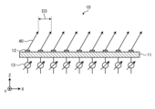
- Fig. 1 is a diagram for explaining the overview of a phased array antenna.
- the phased array antenna 10a includes a substrate 11, a plurality of antenna elements 12, and a plurality of phase shifters 13.
- the substrate 11 is, for example, a dielectric substrate on which multiple antenna elements 12 are arranged.
- the multiple antenna elements 12 are arranged in a one-dimensional or two-dimensional array at equal intervals on the substrate 11 in the XY plane.
- the multiple antenna elements 12 transmit radio waves in a predetermined direction in the +Z axis direction.
- the multiple antenna elements 12 receive radio waves arriving from a predetermined direction in the +Z axis direction.
- the spacing D1 between the antenna elements 12 is ⁇ /2, where ⁇ is the wavelength of the radio waves transmitted and received by the antenna elements 12.
- 32 antenna elements 12 are arranged one-dimensionally at ⁇ /2 intervals along the X axis direction.
- the multiple phase shifters 13 are provided for each antenna element 12. Each of the multiple phase shifters 13 controls the phase of the corresponding antenna element 12. By controlling the phase of the corresponding antenna element 12, the multiple phase shifters 13 can change the directivity of the radio waves being transmitted and received. In the example shown in FIG. 1, for example, the phase difference between adjacent antenna elements 12 is controlled to 90°.
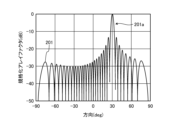
- FIG. 2 is a diagram for explaining the signal level of the transmission radio waves transmitted by the phased array antenna.
- the horizontal axis indicates the direction in which the transmission radio waves are transmitted (deg (degrees)), and the vertical axis indicates the array factor (dB (decibels)) normalized by the maximum value.
- Waveform 201 indicates the signal level of the transmission radio waves transmitted by the phased array antenna 10a shown in FIG. 1.
- phased array antenna 10a is controlled to adjust the phase of each antenna element 12 and transmit the transmission radio waves in a direction of 30°. Therefore, waveform 201 has a main lobe 201a in the direction of 30°.
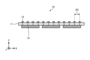
- Fig. 3 is a diagram for explaining a configuration example of the phased array antenna according to the first embodiment.
- the phased array antenna 10 includes a substrate 11, a plurality of antenna elements 12, and a plurality of RFIC chips 14.
- the plurality of phase shifters 13 are omitted.
- the physical length of half the wavelength of the radio waves decreases. For example, when the frequency of the radio waves is 300 GHz (gigahertz), the half wavelength of the radio waves is 0.5. Therefore, when considering a phased array antenna with the same number of antenna elements 12, the area becomes smaller as the frequency increases.
- the phased array antenna 10 usually has an RFIC (Radio-Frequency Integrated Circuits) chip 14 on the side opposite to the side on which the antenna elements 12 are provided. It is difficult to miniaturize the RFIC chip 14 in proportion to the wavelength even if the frequency becomes higher. Therefore, if the elements are arranged according to the size of the RFIC chip 14, the spacing between the antenna elements 12 exceeds ⁇ /2. In the example shown in FIG. 3, the spacing D2 between the antenna elements 12 is ⁇ . Specifically, in the example shown in FIG. 3, 32 antenna elements 12 are arranged one-dimensionally at ⁇ intervals along the X-axis direction, and the phase difference between adjacent antenna elements 12 is controlled to 180°.
- RFIC Radio-Frequency Integrated Circuits
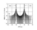
- FIG. 4 is a diagram for explaining the signal level of the transmission radio wave transmitted by the phased array antenna according to the first embodiment.
- the horizontal axis indicates the direction in which the transmission radio wave is transmitted (deg (degrees)), and the vertical axis indicates the array factor (dB (decibels)) normalized by the maximum value.
- a waveform 202 indicates the signal level of the transmission radio wave transmitted by the phased array antenna 10 shown in FIG. 3.
- the phased array antenna 10 is controlled to adjust the phase of each antenna element 12 and transmit the transmission radio wave in a direction of 30°.
- a grating lobe 202b occurs in the direction of -30° in addition to the main lobe 202a in the direction of 30°.
- the present disclosure provides a phased array antenna that has good characteristics even when the spacing between antenna elements 12 of the phased array antenna 10 exceeds ⁇ /2.
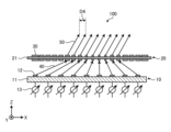
- FIG. 5 is a diagram showing a configuration example of the antenna device according to the first embodiment.
- the antenna device 100 includes a phased array antenna 10 and a radio wave control plate 20.
- the radio wave control plate 20 is provided in the transmission direction of the radio waves transmitted by the phased array antenna 10.
- the radio wave control plate 20 is configured to refract the radio waves transmitted by the phased array antenna 10 in a predetermined direction.
- the radio wave control plate 20 is a type of control unit that refracts the radio waves transmitted from the phased array antenna 10.
- the radio wave control plate 20 comprises a substrate 21 and a number of unit structures 30.
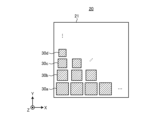
- FIG. 6 is a diagram showing an example of the configuration of the radio wave control plate according to the first embodiment.
- the radio wave control plate 20 is a plate-shaped member configured to transmit the radio waves transmitted by the phased array antenna 10 and enable the formation of a specific beam. For example, when the radio wave control plate 20 receives the radio waves transmitted by the phased array antenna 10, it refracts the transmitted radio waves at a predetermined angle.
- the radio wave control plate 20 can be configured, for example, with a metasurface having an array of resonators that change the phase of the incident wave.
- the radio wave control plate 20 may include, for example, a substrate 21, a unit structure 30a, a unit structure 30b, a unit structure 30c, and a unit structure 30d.
- unit structures 30 When there is no need to distinguish between unit structures 30a to 30d, they are collectively referred to as unit structures 30.
- the unit structure 30a, the unit structure 30b, the unit structure 30c, and the unit structure 30d may be formed on the substrate 2.
- the substrate 21 may be, for example, a dielectric substrate formed of a dielectric material.
- the substrate 21 may have, for example, a rectangular shape, but is not limited to this.
- the unit structure 30a, the unit structure 30b, the unit structure 30c, and the unit structure 30d may be arranged two-dimensionally.
- a plurality of unit structures 30a are arranged along the X-axis direction on one level.
- a plurality of unit structures 30b are arranged along the X-axis direction, for example.
- a plurality of unit structures 30c are arranged along the X-axis direction, for example.
- a plurality of unit structures 30d are arranged along the X-axis direction, for example.
- the unit structures 30a, 30b, 30c, and 30d are arranged periodically along the Y-axis direction.
- Unit structure 30a, unit structure 30b, unit structure 30c, and unit structure 30d each have a different size.
- unit structure 30a is the largest, followed by unit structure 30b, unit structure 30c, and unit structure 30d in order of size.
- radio wave control plate 20 has a structure in which multiple unit structures 30 of different sizes are periodically arranged.
- the unit structures 30a to 30d each have a different amount of phase change when radio waves pass through them. That is, the unit structures 30a to 30d are periodically arranged so that there is a gradient in the amount of phase change.
- the unit structures 30a to 30d each have a rectangular shape, but are not limited to this. By changing the size and shape of the unit structures 30a to 30d, the amount of phase change of the passing radio waves can be adjusted. In other words, the radio wave control plate 20 can refract the transmitted radio waves from the phased array antenna 10 in a desired direction or form a desired beam shape by changing the arrangement method and size of the unit structures 30a to 30d.
- FIG. 7 is a diagram for explaining the transmission direction of the transmission radio waves of a phased array antenna according to a comparative example.
- the phased array antenna 10 transmits transmission radio waves 40 from each antenna element 12, for example, in a direction of 30°.
- the spacing between the antenna elements 12 is ⁇
- the spacing D3 of the transmission radio waves 40 is ⁇ .
- grating lobes occur in the transmission radio waves 40 in the direction of -30°.
- the antenna device 100 is configured to refract the transmission radio wave 40 transmitted by the phased array antenna 10, in which the spacing between the antenna elements 12 is ⁇ , and emit the transmitted wave 50 in a direction of 30°.
- the phased array antenna 10 transmits the transmission radio wave 40 to the radio wave control plate 20 based on the phase gradient of the unit structure 30 of the radio wave control plate 20 so that the radio wave control plate 20 emits the transmitted wave 50 in a direction of 30°.
- the phased array antenna 10 controls the direction in which the transmission radio wave 40 is transmitted according to the phase gradient of the unit structure 30 of the radio wave control plate 20. In the example shown in FIG.
- the spacing D4 of the transmitted wave 50 is ⁇ /2. That is, by including the radio wave control plate 20, the antenna device 100 can transmit transmission radio waves in which the spacing between the antenna elements 12 of the phased array antenna 10 can be considered to be ⁇ /2. As a result, even if the spacing between the antenna elements 12 is ⁇ , grating lobes can be suppressed.
- the phased array antenna 10 includes a first antenna element 121 , a second antenna element 122 , a third antenna element 123 , a fourth antenna element 124, a fifth antenna element 125 , a sixth antenna element 126 , a seventh antenna element 127 , and an eighth antenna element 128.
- the antenna elements 12 are arranged one-dimensionally at equal intervals along the X-axis direction.
- the interval D between the antenna elements 12 is ⁇ .
- the Y coordinate of the center of the phased array antenna 10 is set to 0.
- the radio wave control plate 20 is disposed at a position zm from the phased array antenna 10 in the transmission direction of the transmitted radio wave from the phased array antenna 10. zm is 10 ⁇ .
- the X and Y coordinates of the radio wave control plate 20 are set to 0.
- a reception point P indicates a reception position of a radio wave transmitted by the antenna device 100.
- the reception point P is set on a circle C at a distance d2,k from the origin in the ZX plane, where d2,k is 100 m.
- the calculation conditions for the characteristics of the antenna device 100 will be described.
- the phased array antenna 10 is port 1.
- the receiving point P is port 2.
- the angle between the line connecting the origin and the receiving point P and the Z axis is ⁇ .
- the transmission coefficient S21( ⁇ ) of the radio wave control plate 20 at this time is calculated using the following formula (1), and the radiation pattern is calculated by changing ⁇ .
- s i,k represents the transmission coefficient of a path that passes from the i-th antenna element 12 of the phased array antenna 10 through the k-th unit structure 30 of the radio wave control plate 20 to the reception point P.
- s i,k is calculated by the following formula (2).
- FIG. 11 is a diagram for explaining the conditions for calculating the transmission coefficient of the radio wave control plate according to the first embodiment.
- the transmission point P1 indicates the position of the antenna element 12 that transmits the transmission radio wave.
- the reception point P2 indicates the reception position of the transmission wave emitted from the radio wave control plate 20.
- the unit structure 30 is a square with one side of ⁇ A.
- A is the area of the unit structure 30.
- ⁇ i,k is the angle between the direction of the i-th antenna element 12 as seen from the k-th unit structure 30 k and the Z axis.
- ⁇ 2,k is the angle between the direction of the reception point P as seen from the k-th unit structure 30 and the Z axis.
- d i,k is the distance between the k-th unit structure 30 k and the i-th antenna element 12 i .
- d 2,k is the distance between the k-th unit structure 30 k and the reception point P.
- ⁇ k indicates the phase change of the k-th unit structure.
- ⁇ is the wavelength of the transmission radio wave transmitted by the phased array antenna 10.
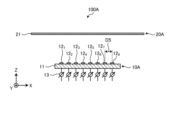
- FIG. 12 is a diagram for explaining a simulation condition of an antenna device according to a first comparative example of the first embodiment.
- Fig. 13 is a diagram showing a calculation result of
- the antenna device 100A includes a phased array antenna 10A and a radio wave control plate 20A.
- the phased array antenna 10A includes a substrate 11, a first antenna element 121 to an eighth antenna element 128 , and a plurality of phase shifters 13.
- the first antenna element 121 to the eighth antenna element 128 are arranged at equal intervals along the X-axis direction.
- the interval D5 between adjacent antenna elements 12 among the first antenna element 121 to the eighth antenna element 128 is ⁇ /2.
- the phase difference between each antenna element 12 is ⁇ 90°.
- the plurality of phase shifters 13 are provided for each of the first antenna element 121 to the eighth antenna element 128 .
- the transmission phases of the unit structures 30 arranged on the radio wave control plate 20A are all equal. Therefore, although the unit structures 30 are actually arranged on the radio wave control plate 20A, they are omitted in FIG. 12.
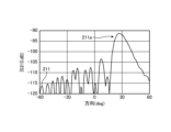
- Waveform 211 indicates the signal level of the transmission radio wave transmitted by antenna device 100A shown in FIG. 12.
- antenna device 100A is controlled to adjust the phase of each antenna element 12 and transmit the transmission radio wave in a direction of 30°.
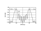
- Fig. 14 is a diagram for explaining the simulation conditions of the antenna device according to the second comparative example of the first embodiment.
- Fig. 15 is a diagram showing a simulation result of the transmission wave of the antenna device according to the second comparative example of the first embodiment.
- the antenna device 100B includes a phased array antenna 10B and a radio wave control plate 20B.
- the phased array antenna 10B differs from the phased array antenna 10A shown in Fig. 12 in that the interval D6 between adjacent antenna elements 12 from the first antenna element 121 to the eighth antenna element 128 is ⁇ . Also, in the phased array antenna 10B, the phase difference between each antenna element 12 is -180°.
- the configuration of the radio wave control plate 20B is the same as that of the radio wave control plate 20A shown in Fig. 12.
- Waveform 212 indicates the signal level of the transmission radio wave transmitted by antenna device 100B shown in FIG. 14.
- antenna device 100B is controlled to adjust the phase of each antenna element 12 and transmit the transmission radio wave in a 30° direction.
- waveform 212 there is a main lobe 212a in the 30° direction, and a grating lobe 212b in the -30° direction.
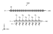
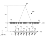
- Fig. 16 is a diagram for explaining the simulation conditions of the antenna device according to the first embodiment.
- the antenna device 100C includes a phased array antenna 10C and a radio wave control plate 20C.
- the configuration of the phased array antenna 10C is the same as that of the phased array antenna 10B shown in FIG. 14.
- the radio wave control plate 20C comprises a substrate 21 and a plurality of unit structures 30.
- the plurality of unit structures 30 have a distribution of transmission phases that diffuse the radio waves transmitted from the phased array antenna 10C.
- the phase distribution of the transmission phases of the plurality of unit structures 30 is set according to the wavelength of the transmitted radio waves.
- FIG. 17 is a diagram for explaining a method for setting the phase distribution of the unit structures of the radio wave control plate according to the first embodiment.
- the distance between the phased array antenna 10C and the radio wave control plate 20C is zm .
- the position of the focal point P3 is set at a position 2zm away from the radio wave control plate 20C.
- zm is, for example, 10m.
- the phase distribution of each unit structure 30 is set according to the following formula (3).
- Equation (3) is an equation for setting a phase distribution in which the focal point of the unit structure 30 as a concave lens is ⁇ 2z m .
- the radio wave control plate 20C diffuses radio waves from a distant place toward the phased array antenna 10C, and conversely, it is possible to control the radio waves from the phased array antenna 10C to form a beam in a predetermined direction.
- the presence of the radio wave control plate 20C allows an antenna device including the phased array antenna 10C and the radio wave control plate 20C to operate equivalently in the same manner as a phased array antenna with a narrow spacing.
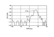
- Waveform 213 indicates the signal level of the transmission radio waves transmitted by the antenna device 100C shown in FIG. 17.
- the antenna device 100C is controlled to adjust the phase of each antenna element 12 and transmit the transmission radio waves in a 30° direction.
- the antenna device 100C can suppress the grating lobes 212b that were generated in FIG. 15.
- the first embodiment combines a phased array antenna with a radio wave control plate to suppress grating lobes that occur when the spacing between antenna elements of a phased array antenna is equal to or greater than half the wavelength of the transmitted radio wave.
- the antenna device 100 has been described as including a radio wave control plate 20 that refracts the transmission radio wave transmitted by the phased array antenna 10, but the present disclosure is not limited thereto.
- a dielectric dielectric lens
- a dielectric plate having a dielectric constant distribution dielectric constant near the center is lower than the periphery.
- the phased array antenna 10C and the antenna device including the dielectric lens can operate in the same manner as a phased array antenna with a narrow spacing equivalently, as in the first embodiment.
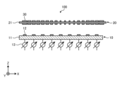
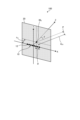
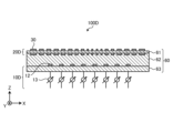
- Fig. 19 illustrates an example of the configuration of an antenna device according to the second embodiment.
- Fig. 19 is a diagram illustrating an example of the configuration of an antenna device according to the second embodiment.
- the antenna device 100D includes a phased array antenna 10D, a radio wave control plate 20D, and a substrate 60.
- the substrate 60 is, for example, a dielectric substrate.
- the substrate 60 has three regions: a first dielectric layer 61, a second dielectric layer 62, and a third dielectric layer 63.
- the phased array antenna 10D comprises a plurality of antenna elements 12, a plurality of phase shifters 13, and a third dielectric layer 63.
- the third dielectric layer 63 can be regarded as a dielectric substrate on which the plurality of antenna elements 12 are arranged.
- the configuration of the phased array antenna 10D is the same as the configuration of the phased array antenna 10C shown in FIG. 16.
- the radio wave control plate 20D comprises a plurality of unit structures 30 and a first dielectric layer 61.
- the first dielectric layer 61 can be regarded as a dielectric substrate on which the plurality of unit structures 30 are arranged.
- the configuration of the radio wave control plate 20D is the same as that of the radio wave control plate 20C shown in FIG. 16.
- the second dielectric layer 62 is located between the first dielectric layer 61 and the third dielectric layer 63.
- the first dielectric layer 61, the second dielectric layer 62, and the third dielectric layer 63 can be considered to be an integrally formed dielectric substrate.
- the antenna device 100D is configured by integrating the phased array antenna 10D and the radio wave control plate 20D.
- the distance between the phased array antenna 10D and the radio wave control plate 20D is stabilized, so that grating lobes can be appropriately suppressed.
- the antenna device 100 includes a phased array antenna 10 including a plurality of antenna elements 12, and a control unit that is provided in the transmission direction of radio waves transmitted by the phased array antenna 10 and that controls the transmission radio waves so that a predetermined beam pattern is formed by forming the transmission phase to differ depending on the position of incidence of the transmission radio waves, and the plurality of antenna elements 12 are arranged at intervals wider than half the wavelength of the transmission radio waves.
- a control unit in the transmission direction of the transmission radio waves of the phased array antenna 10, it is possible to suppress grating lobes.
- the antenna device 100 according to the second aspect of the present disclosure is the antenna device 100 according to the first aspect, in which the control unit is a radio wave control plate 20 including a plurality of unit structures 30 arranged two-dimensionally, and the plurality of unit structures 30 have a distribution of transmission phases that diffuse the transmitted radio waves. According to the present disclosure, grating lobes can be appropriately suppressed.
- the antenna device 100 according to the third aspect of the present disclosure is the antenna device 100 according to the first or second aspect, in which the distribution of the transmission phase of the multiple unit structures 30 is set according to the wavelength of the transmitted radio wave. According to the present disclosure, grating lobes can be appropriately suppressed.
- control section is a dielectric material having a concave lens shape. According to the present disclosure, grating lobes can be appropriately suppressed.
- the phased array antenna 10 and the control unit are integrally configured.
- the antenna device 100 can be configured as a single device.
- the radio wave control plate 20 is provided in the transmission direction of radio waves transmitted by a phased array antenna 10 including a plurality of antenna elements 12, and includes a plurality of unit structures 30 arranged two-dimensionally, and the phases of the plurality of unit structures 30 have a distribution of transmission phases that diffuse the transmitted radio waves according to the wavelength of the transmitted radio waves. According to the present disclosure, it is possible to suppress grating lobes that occur in the transmitted radio waves of the phased array antenna 10.
Landscapes
- Variable-Direction Aerials And Aerial Arrays (AREA)
Abstract
Ce dispositif d'antenne comprend : une antenne réseau à commande de phase comprenant une pluralité d'éléments d'antenne ; et une unité de commande qui est disposée dans la direction de transmission d'une onde radio transmise par l'antenne réseau à commande de phase, qui est formée de telle sorte que la phase de transmission diffère en fonction de la position où l'onde radio de transmission est incidente, et qui commande l'onde radio de transmission de façon à former un motif de faisceau prescrit. Les éléments d'antenne sont agencés à un intervalle plus large que la demi-longueur d'onde de l'onde radio de transmission.
Priority Applications (2)
| Application Number | Priority Date | Filing Date | Title |
|---|---|---|---|
| PCT/JP2023/022478 WO2024257350A1 (fr) | 2023-06-16 | 2023-06-16 | Dispositif d'antenne et plaque de commande d'onde radio |
| JP2023559000A JP7634715B1 (ja) | 2023-06-16 | 2023-06-16 | アンテナ装置および電波制御板 |
Applications Claiming Priority (1)
| Application Number | Priority Date | Filing Date | Title |
|---|---|---|---|
| PCT/JP2023/022478 WO2024257350A1 (fr) | 2023-06-16 | 2023-06-16 | Dispositif d'antenne et plaque de commande d'onde radio |
Publications (1)
| Publication Number | Publication Date |
|---|---|
| WO2024257350A1 true WO2024257350A1 (fr) | 2024-12-19 |
Family
ID=93851638
Family Applications (1)
| Application Number | Title | Priority Date | Filing Date |
|---|---|---|---|
| PCT/JP2023/022478 Pending WO2024257350A1 (fr) | 2023-06-16 | 2023-06-16 | Dispositif d'antenne et plaque de commande d'onde radio |
Country Status (2)
| Country | Link |
|---|---|
| JP (1) | JP7634715B1 (fr) |
| WO (1) | WO2024257350A1 (fr) |
Citations (5)
| Publication number | Priority date | Publication date | Assignee | Title |
|---|---|---|---|---|
| JPH09162638A (ja) * | 1995-12-08 | 1997-06-20 | Dx Antenna Co Ltd | 平面アレーアンテナ |
| JPH1065439A (ja) * | 1996-08-22 | 1998-03-06 | Mitsubishi Electric Corp | アレーアンテナ装置 |
| JP2018157541A (ja) * | 2017-03-17 | 2018-10-04 | アイソトロピック システムズ リミテッドIsotropic Systems Ltd. | レンズアンテナシステム |
| JP2021516005A (ja) * | 2018-02-22 | 2021-06-24 | ユニバーシティ オブ マサチューセッツ | アンテナハードウェア及び制御 |
| JP2023509575A (ja) * | 2020-01-08 | 2023-03-09 | メタウェーブ コーポレーション | 2次元ビームスキャニングを有するリフレクトアレイアンテナ |
Family Cites Families (1)
| Publication number | Priority date | Publication date | Assignee | Title |
|---|---|---|---|---|
| CN111834756B (zh) * | 2019-04-15 | 2021-10-01 | 华为技术有限公司 | 天线阵列及无线设备 |
-
2023
- 2023-06-16 WO PCT/JP2023/022478 patent/WO2024257350A1/fr active Pending
- 2023-06-16 JP JP2023559000A patent/JP7634715B1/ja active Active
Patent Citations (5)
| Publication number | Priority date | Publication date | Assignee | Title |
|---|---|---|---|---|
| JPH09162638A (ja) * | 1995-12-08 | 1997-06-20 | Dx Antenna Co Ltd | 平面アレーアンテナ |
| JPH1065439A (ja) * | 1996-08-22 | 1998-03-06 | Mitsubishi Electric Corp | アレーアンテナ装置 |
| JP2018157541A (ja) * | 2017-03-17 | 2018-10-04 | アイソトロピック システムズ リミテッドIsotropic Systems Ltd. | レンズアンテナシステム |
| JP2021516005A (ja) * | 2018-02-22 | 2021-06-24 | ユニバーシティ オブ マサチューセッツ | アンテナハードウェア及び制御 |
| JP2023509575A (ja) * | 2020-01-08 | 2023-03-09 | メタウェーブ コーポレーション | 2次元ビームスキャニングを有するリフレクトアレイアンテナ |
Also Published As
| Publication number | Publication date |
|---|---|
| JP7634715B1 (ja) | 2025-02-21 |
| JPWO2024257350A1 (fr) | 2024-12-19 |
Similar Documents
| Publication | Publication Date | Title |
|---|---|---|
| JP7224174B2 (ja) | 電子装置およびレーダー制御方法 | |
| JP6973607B2 (ja) | アンテナモジュールおよびそれを搭載した通信装置 | |
| CA2793316C (fr) | Reseau d'alimentation rf pour des ensembles orientes electroniquement, a ouverture active, modulaires | |
| EP3783738B1 (fr) | Élargissement de faisceau à large bande pour des systèmes d'antenne réseau à commande de phase | |
| US9972915B2 (en) | Optimized true-time delay beam-stabilization techniques for instantaneous bandwith enhancement | |
| JP7156518B2 (ja) | サブアレイアンテナ、アレイアンテナ、アンテナモジュール、および通信装置 | |
| US9054414B2 (en) | Antenna system for low-earth-orbit satellites | |
| JPWO2020261807A1 (ja) | アンテナモジュールおよびそれを搭載した通信装置 | |
| US12218435B2 (en) | Multi-beam on receive electronically-steerable antenna | |
| CN112072309B (zh) | 一种步进补偿低成本相控阵天线架构及其设计方法 | |
| WO2019170541A1 (fr) | Réseaux de plans focaux à balayage extrême utilisant un concept à double réflecteur avec éclairage de réseau uniforme | |
| JP7634715B1 (ja) | アンテナ装置および電波制御板 | |
| US10741917B2 (en) | Power division in antenna systems for millimeter wave applications | |
| Rahimian | Design and Performance of a K U-Band Rotman Lens Beamforming Network for Satellite Systems | |
| US12132255B2 (en) | Multibeam antenna | |
| CN120222040A (zh) | 随机旋转组阵的同心圆环稀布阵圆极化相控阵天线设计方法 | |
| KR102021888B1 (ko) | 모노펄스 시스템을 위한 나선형 능동 위상배열 안테나 | |
| US12119557B2 (en) | Grating lobe cancellation | |
| Ghate et al. | Quasi-optical beamforming approach using vertically oriented dielectric wedges | |
| Laue et al. | Design and analysis of a proof-of-concept checkered-network compressive array | |
| WO2021106003A1 (fr) | Réseau d'antennes connecté à un guide d'ondes métalliques | |
| TWI797919B (zh) | 波束成型裝置及波束控制方法 | |
| CN116315676B (zh) | 一种相控阵阵面及阵面优化方法 | |
| JP7457073B2 (ja) | ビーム形成装置およびビーム制御方法 | |
| WO2025249160A1 (fr) | Dispositif radar |
Legal Events
| Date | Code | Title | Description |
|---|---|---|---|
| WWE | Wipo information: entry into national phase |
Ref document number: 2023559000 Country of ref document: JP |
|
| 121 | Ep: the epo has been informed by wipo that ep was designated in this application |
Ref document number: 23941649 Country of ref document: EP Kind code of ref document: A1 |
|
| NENP | Non-entry into the national phase |
Ref country code: DE |