WO2024257419A1 - Circuit haute fréquence et dispositif de communication - Google Patents
Circuit haute fréquence et dispositif de communication Download PDFInfo
- Publication number
- WO2024257419A1 WO2024257419A1 PCT/JP2024/008975 JP2024008975W WO2024257419A1 WO 2024257419 A1 WO2024257419 A1 WO 2024257419A1 JP 2024008975 W JP2024008975 W JP 2024008975W WO 2024257419 A1 WO2024257419 A1 WO 2024257419A1
- Authority
- WO
- WIPO (PCT)
- Prior art keywords
- band
- frequency
- terminal
- signal
- filter
- Prior art date
- Legal status (The legal status is an assumption and is not a legal conclusion. Google has not performed a legal analysis and makes no representation as to the accuracy of the status listed.)
- Ceased
Links
Images








Classifications
-
- H—ELECTRICITY
- H04—ELECTRIC COMMUNICATION TECHNIQUE
- H04B—TRANSMISSION
- H04B1/00—Details of transmission systems, not covered by a single one of groups H04B3/00 - H04B13/00; Details of transmission systems not characterised by the medium used for transmission
- H04B1/06—Receivers
- H04B1/10—Means associated with receiver for limiting or suppressing noise or interference
-
- H—ELECTRICITY
- H04—ELECTRIC COMMUNICATION TECHNIQUE
- H04B—TRANSMISSION
- H04B1/00—Details of transmission systems, not covered by a single one of groups H04B3/00 - H04B13/00; Details of transmission systems not characterised by the medium used for transmission
-
- H—ELECTRICITY
- H04—ELECTRIC COMMUNICATION TECHNIQUE
- H04B—TRANSMISSION
- H04B1/00—Details of transmission systems, not covered by a single one of groups H04B3/00 - H04B13/00; Details of transmission systems not characterised by the medium used for transmission
- H04B1/005—Details of transmission systems, not covered by a single one of groups H04B3/00 - H04B13/00; Details of transmission systems not characterised by the medium used for transmission adapting radio receivers, transmitters andtransceivers for operation on two or more bands, i.e. frequency ranges
- H04B1/0053—Details of transmission systems, not covered by a single one of groups H04B3/00 - H04B13/00; Details of transmission systems not characterised by the medium used for transmission adapting radio receivers, transmitters andtransceivers for operation on two or more bands, i.e. frequency ranges with common antenna for more than one band
- H04B1/0057—Details of transmission systems, not covered by a single one of groups H04B3/00 - H04B13/00; Details of transmission systems not characterised by the medium used for transmission adapting radio receivers, transmitters andtransceivers for operation on two or more bands, i.e. frequency ranges with common antenna for more than one band using diplexing or multiplexing filters for selecting the desired band
-
- H—ELECTRICITY
- H04—ELECTRIC COMMUNICATION TECHNIQUE
- H04B—TRANSMISSION
- H04B1/00—Details of transmission systems, not covered by a single one of groups H04B3/00 - H04B13/00; Details of transmission systems not characterised by the medium used for transmission
- H04B1/005—Details of transmission systems, not covered by a single one of groups H04B3/00 - H04B13/00; Details of transmission systems not characterised by the medium used for transmission adapting radio receivers, transmitters andtransceivers for operation on two or more bands, i.e. frequency ranges
- H04B1/0053—Details of transmission systems, not covered by a single one of groups H04B3/00 - H04B13/00; Details of transmission systems not characterised by the medium used for transmission adapting radio receivers, transmitters andtransceivers for operation on two or more bands, i.e. frequency ranges with common antenna for more than one band
- H04B1/006—Details of transmission systems, not covered by a single one of groups H04B3/00 - H04B13/00; Details of transmission systems not characterised by the medium used for transmission adapting radio receivers, transmitters andtransceivers for operation on two or more bands, i.e. frequency ranges with common antenna for more than one band using switches for selecting the desired band
-
- H—ELECTRICITY
- H04—ELECTRIC COMMUNICATION TECHNIQUE
- H04B—TRANSMISSION
- H04B1/00—Details of transmission systems, not covered by a single one of groups H04B3/00 - H04B13/00; Details of transmission systems not characterised by the medium used for transmission
- H04B1/38—Transceivers, i.e. devices in which transmitter and receiver form a structural unit and in which at least one part is used for functions of transmitting and receiving
- H04B1/40—Circuits
- H04B1/50—Circuits using different frequencies for the two directions of communication
Definitions
- the present invention relates to high-frequency circuits and communication devices.
- Multiband front-end circuits are required to transmit and receive multiple high-frequency signals with low loss and high isolation.
- Patent Document 1 discloses a high-frequency module (high-frequency circuit) in which multiple filters with different passbands are connected to an antenna via a multiplexer (switch).
- 3GPP (3rd Generation Partnership Project) is considering simultaneous transmission of signals in two communication bands with partially overlapping frequency bands.
- the present invention aims to provide a small high-frequency circuit and communication device that can simultaneously transmit signals in two communication bands with partially overlapping frequency bands while minimizing degradation of isolation and reception sensitivity.
- a high-frequency circuit comprises a first filter having a passband including a first frequency band, which is one of the transmission band and reception band of a first communication band, and a second filter having a passband including a second frequency band, which is the other of the transmission band and reception band of a second communication band, the first communication band and the second communication band being a band combination capable of simultaneous communication, the first frequency band including a first subband that overlaps with the second frequency band and a second subband that does not overlap with the second frequency band, the second frequency band including the first subband and a third subband that does not overlap with the first communication band, and the passband of the first filter is variable to a first passband including the first subband and the second subband, and a second passband including the second subband and narrower than the first passband.
- the present invention makes it possible to provide a small high-frequency circuit and communication device that can simultaneously transmit signals in two communication bands with partially overlapping frequency bands while minimizing degradation of isolation and reception sensitivity.
- FIG. 1 is a circuit configuration diagram of a high-frequency circuit and a communication device according to an embodiment.
- FIG. 2 is a diagram illustrating the frequency relationship of communication bands and the pass characteristics of filters applied to the high-frequency circuit according to the embodiment.
- FIG. 3A is a circuit diagram showing a connection state of a first switch when a signal in a first communication band is transmitted alone in the high-frequency circuit according to the embodiment.
- FIG. 3B is a circuit diagram showing a connection state of the first switch when signals in the first communication band and signals in the second communication band are transmitted simultaneously in the high-frequency circuit according to the embodiment.
- FIG. 4A is a diagram illustrating the frequency relationship of communication bands and the pass characteristics of filters applied to the high-frequency circuit according to the first modification.
- FIG. 4B is a diagram illustrating the frequency relationship of communication bands and the pass characteristics of filters applied to the high-frequency circuit according to the second modification.
- FIG. 5A is a diagram illustrating a first example of a circuit configuration of a first filter according to an embodiment.
- FIG. 5B is a diagram illustrating a second example of the circuit configuration of the first filter according to the embodiment.
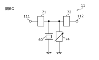
- FIG. 5C is a diagram illustrating a third example of a circuit configuration of the first filter according to the embodiment.
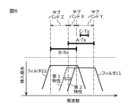
- FIG. 6 is a diagram illustrating the frequency relationship of communication bands and the pass characteristics of filters applied to the high-frequency circuit according to the third modification.
- FIG. 7A is a circuit configuration diagram showing a first connection state of a high-frequency circuit according to Modification 4. As shown in FIG. FIG.
- FIG. 7B is a diagram illustrating the frequency relationship of communication bands applied to the high-frequency circuit according to the fourth modification, and the pass characteristic of a filter in the first connection state.
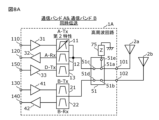
- FIG. 8A is a circuit configuration diagram showing a second connection state of the high-frequency circuit according to the fourth modification.
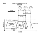
- FIG. 8B is a diagram illustrating the frequency relationship of communication bands applied to the high-frequency circuit according to the fourth modification, and the pass characteristic of the filter in the second connection state.
- FIG. 9A is a circuit configuration diagram of a high-frequency circuit and a diverter circuit according to a fifth modified example.
- FIG. 9B is a circuit configuration diagram of a high-frequency circuit and a primary circuit according to Modification 6.
- each figure is a schematic diagram in which emphasis, omissions, or adjustments to the ratio have been made as appropriate to illustrate the present invention, and is not necessarily an exact illustration, and may differ from the actual shape, positional relationship, and ratio.
- the same reference numerals are used for substantially the same configuration, and duplicate explanations may be omitted or simplified.
- connection refers not only to direct connection by a connection terminal and/or wiring conductor, but also to electrical connection via other circuit elements. Additionally, “connected between A and B” refers to connection to A and B on the path connecting A and B.
- a "transmission path” refers to a transmission line that is composed of a wiring through which a high-frequency transmission signal propagates, an electrode directly connected to the wiring, and a terminal directly connected to the wiring or the electrode.
- a “reception path” refers to a transmission line that is composed of a wiring through which a high-frequency reception signal propagates, an electrode directly connected to the wiring, and a terminal directly connected to the wiring or the electrode.
- the passband of a filter is defined as the frequency band between two frequencies that are 3 dB greater than the minimum insertion loss within the passband.
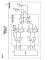
- Fig. 1 is a circuit configuration diagram of a high-frequency circuit 1 and a communication device 4 according to the embodiment.
- the communication device 4 includes a high-frequency circuit 1, antennas 2a and 2b, and an RF signal processing circuit (RFIC) 3.
- RFIC RF signal processing circuit
- the high-frequency circuit 1 transmits high-frequency signals between the antennas 2a and 2b and the RFIC 3.
- the detailed circuit configuration of the high-frequency circuit 1 will be described later.
- Antenna 2a is connected to antenna terminal 101 of high frequency circuit 1, and transmits high frequency signals output from high frequency circuit 1, and also receives high frequency signals from the outside and outputs them to high frequency circuit 1.
- Antenna 2b is connected to antenna terminal 102 of high frequency circuit 1, and transmits high frequency signals output from high frequency circuit 1, and also receives high frequency signals from the outside and outputs them to high frequency circuit 1.
- the RFIC3 is an example of a signal processing circuit that processes high-frequency signals. Specifically, the RFIC3 processes the high-frequency received signal input via the receiving path of the high-frequency circuit 1 by down-conversion or the like, and outputs the received signal generated by the signal processing to a baseband signal processing circuit (BBIC: not shown). The RFIC3 also processes the transmission signal input from the BBIC by up-conversion or the like, and outputs the high-frequency transmission signal generated by the signal processing to the transmitting path of the high-frequency circuit 1. The RFIC3 also has a control unit that controls the switches and amplifiers of the high-frequency circuit 1. Note that some or all of the functions of the RFIC3 as a control unit may be implemented outside the RFIC3, for example, in the BBIC or the high-frequency circuit 1.
- antennas 2a and 2b are not essential components of communication device 4 in this embodiment.
- the high-frequency circuit 1 includes filters 11, 12, 21, and 22, a switch 50, power amplifiers 31 and 41, low-noise amplifiers 32 and 42, antenna terminals 101 and 102, high-frequency input terminals 110 and 130, and high-frequency output terminals 120 and 140.
- the antenna terminal 101 is connected to the antenna 2a and the terminal 50a of the switch 50.
- the antenna terminal 102 is connected to the antenna 2b and the terminal 50b of the switch 50.
- the radio frequency input terminal 110 is connected to the RFIC 3 and the power amplifier 31, and is a terminal for receiving a radio frequency transmission signal from the RFIC 3.
- the radio frequency input terminal 130 is connected to the RFIC 3 and the power amplifier 41, and is a terminal for receiving a radio frequency transmission signal from the RFIC 3.
- the radio frequency output terminal 120 is connected to the RFIC 3 and the low noise amplifier 32, and is a terminal for outputting a radio frequency reception signal to the RFIC 3.
- the radio frequency output terminal 140 is connected to the RFIC 3 and the low noise amplifier 42, and is a terminal for outputting a radio frequency reception signal to the RFIC 3.
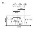
- FIG. 2 illustrates the frequency relationship between communication band A and communication band B applied to high-frequency circuit 1 according to the embodiment, and the pass characteristics of filters 11 and 22.
- communication band A is an example of a first communication band
- communication band B is an example of a second communication band.
- Communication band A and communication band B are a band combination that allows simultaneous communication. As shown in FIG. 2, the transmission band (A-Tx) of communication band A and the reception band (B-Rx) of communication band B partially overlap in frequency.
- the transmission band of communication band A is an example of a first frequency band
- the reception band of communication band B is an example of a second frequency band.
- the transmission band of communication band A includes subband X (first subband) that overlaps with the reception band of communication band B, and subband Y (second subband) that does not overlap with the reception band of communication band B.
- the reception band of communication band B includes subband X (first subband) that overlaps with the transmission band of communication band A, and subband Z (third subband) that does not overlap with the transmission band of communication band A.
- one band partially overlaps with another band does not only mean that a portion of the frequency range of one band overlaps with a portion of the frequency range of the other band, but also means that a point at the low frequency end or high frequency end of one band coincides with a point at the high frequency end or low frequency end of the other band, but does not coincide at other frequencies.
- subband X may be composed of only one predetermined frequency point.
- each of communication band A, communication band B, and communication band C and communication band D described below means a frequency band predefined by a standardization organization (e.g., 3GPP (registered trademark), IEEE (Institute of Electrical and Electronics Engineers), etc.) for a communication system constructed using radio access technology (RAT).
- a standardization organization e.g., 3GPP (registered trademark), IEEE (Institute of Electrical and Electronics Engineers), etc.
- RAT radio access technology
- Examples of communication systems that can be used include, but are not limited to, an LTE (Long Term Evolution) system, a 5G (5th Generation)-NR (New Radio) system, and a WLAN (Wireless Local Area Network) system.
- Filter 11 is an example of a first filter, and has a passband that includes the transmission band (first frequency band) of communication band A. More specifically, the passband of filter 11 is variable between a first passband that includes subband X and subband Y, and a second passband that includes subband Y and is narrower than the first passband. In other words, filter 11 varies between a first characteristic having a first passband and a second characteristic having a second passband, for example, by a control signal output from RFIC 3. One end of filter 11 is connected to terminal 50c (first terminal) of switch 50 (first switch), and the other end of filter 11 is connected to the output terminal of power amplifier 31.
- Filter 22 is an example of a second filter, and has a pass band that includes the reception band (second frequency band) of communication band B.
- One end of filter 22 is connected to terminal 50d (second terminal) of switch 50 (first switch), and the other end of filter 22 is connected to the input terminal of low-noise amplifier 42.
- the filter 12 has a pass band that includes the reception band of the communication band A.
- One end of the filter 12 is connected to the terminal 50c of the switch 50, and the other end of the filter 12 is connected to the input terminal of the low noise amplifier 32.
- the filter 21 has a passband that includes the transmission band of the communication band B. One end of the filter 21 is connected to the terminal 50d of the switch 50, and the other end of the filter 21 is connected to the output terminal of the power amplifier 41.
- Switch 50 is an example of a first switch, and has terminal 50a (first antenna connection terminal), terminal 50b (second antenna connection terminal), terminal 50c (first terminal), and terminal 50d (second terminal).
- Switch 50 is a DPDT (Double Pole Double Throw) type switch, and switches between connection and non-connection between terminals 50a and 50c, between connection and non-connection between terminals 50a and 50d, between connection and non-connection between terminals 50b and 50c, and between connection and non-connection between terminals 50b and 50d.
- Terminal 50a is connected to antenna terminal 101
- terminal 50b is connected to antenna terminal 102
- terminal 50c is connected to filters 11 and 12
- terminal 50d is connected to filters 21 and 22.
- the switch 50 switches between the connection and disconnection between the antenna 2a and the filters 11 and 12, between the connection and disconnection between the antenna 2a and the filters 21 and 22, between the connection and disconnection between the antenna 2b and the filters 11 and 12, and between the connection and disconnection between the antenna 2b and the filters 21 and 22.
- the power amplifier 31 has an output terminal connected to the filter 11 and an input terminal connected to the radio frequency input terminal 110.
- the power amplifier 31 amplifies the radio frequency transmission signal (hereinafter referred to as the transmission signal) of the communication band A input from the radio frequency input terminal 110.
- the output terminal of the power amplifier 41 is connected to the filter 21, and the input terminal is connected to the radio frequency input terminal 130.
- the power amplifier 41 amplifies the transmission signal of the communication band B input from the radio frequency input terminal 130.
- the input terminal of the low-noise amplifier 32 is connected to the filter 12, and the output terminal is connected to the high-frequency output terminal 120.
- the low-noise amplifier 32 amplifies the high-frequency reception signal (hereinafter referred to as the reception signal) of the communication band A input from the antenna terminal 101 or 102.
- the input terminal of the low noise amplifier 42 is connected to the filter 22, and the output terminal is connected to the high frequency output terminal 140.
- the low noise amplifier 42 amplifies the received signal of the communication band B input from the antenna terminal 101 or 102.
- the high frequency circuit 1 can execute (1) a first mode in which a transmission signal of sub-band Y of communication band A and a reception signal of sub-band Z of communication band B are simultaneously transmitted, (2) a second mode in which a transmission signal of communication band A is transmitted but a reception signal of communication band B is not transmitted, and (3) a third mode in which a reception signal of communication band B is transmitted but a transmission signal of communication band A is not transmitted.
- FIG. 3A is a circuit diagram showing the connection state of the switch 50 when a signal of communication band A is transmitted alone in the high-frequency circuit 1 according to the embodiment.
- FIG. 3B is a circuit diagram showing the connection state of the switch 50 when a transmission signal of communication band A and a reception signal of communication band B are simultaneously transmitted in the high-frequency circuit 1 according to the embodiment.
- the filter 11 when the second mode is executed, the filter 11 is set to the first passband, so that the transmission signal of the communication band A can be transmitted using the entire transmission band of the communication band A.
- the terminals 50a and 50c of the switch 50 are connected as shown in FIG. 3A. Furthermore, when the second mode is executed, it is desirable to disconnect the terminals 50b and 50d of the switch 50. This allows the transmission signal of the communication band A that passes through the filter 11 to be transmitted with low loss.
- the received signal of communication band B can be transmitted using filter 22. Furthermore, when the third mode is executed, terminals 50b and 50d of switch 50 are connected. Furthermore, when the third mode is executed, it is desirable to disconnect terminals 50a and 50c of switch 50. This allows the received signal of communication band B that passes through filter 22 to be transmitted with low loss.
- the filter 11 When the first mode is executed, the filter 11 is set to the second passband, and as shown in FIG. 3B, the terminals 50a and 50c of the switch 50 are connected, and the terminals 50b and 50d are connected. This improves the isolation between the transmission signal of communication band A that passes through the filter 11 and the reception signal of communication band B that passes through the filter 22, and suppresses deterioration of the reception sensitivity of communication band B.
- a so-called coband filter is used that has a passband that includes the partially overlapping transmission band of communication band A and the reception band of communication band B.
- the transmission signal of communication band A it is not possible to prevent the transmission signal of communication band A from leaking into the reception path of communication band B via the coband filter, resulting in a deterioration in the reception sensitivity of communication band B.
- a second example of a conventional configuration for implementing the first mode is one that includes a first high-frequency circuit for transmitting a transmission signal in communication band A and a second high-frequency circuit for transmitting a reception signal in communication band B, with the first and second high-frequency circuits being completely separated.
- the first and second high-frequency circuits are close to each other, the mutual interference between the transmission signal in communication band A and the reception signal in communication band B will become stronger, resulting in poor isolation.
- the circuit will become larger.
- the passband of the filter 11 is variable, so that even if the filter 11 and the filter 22 are placed close to each other, mutual interference between the transmission signal of the communication band A and the reception signal of the communication band B during execution of the first mode can be suppressed, and isolation can be ensured. Therefore, it is possible to provide a small-sized high-frequency circuit 1 that can simultaneously transmit the transmission signal of the communication band A and the reception signal of the communication band B while suppressing the deterioration of isolation and reception sensitivity.
- the switch 50 may be an SPDT (Single Pole Double Throw) type switch instead of a DPDT type switch.
- the first switch has one antenna connection terminal, a first terminal, and a second terminal, and switches between connection and non-connection between the antenna connection terminal and the first terminal, and between connection and non-connection between the antenna connection terminal and the second terminal.
- the antenna connection terminal is connected to one antenna, the first terminal is connected to filters 11 and 12, and the second terminal is connected to filters 21 and 22.
- the filter 11 when the second mode is executed, the filter 11 is set to the first passband, so that the transmission signal of the communication band A can be transmitted using the entire transmission band of the communication band A. Furthermore, when the second mode is executed, the antenna connection terminal of the first switch is connected to the first terminal. Furthermore, when the second mode is executed, it is desirable to disconnect the antenna connection terminal of the first switch from the second terminal. This allows the transmission signal of the communication band A that passes through the filter 11 to be transmitted with low loss.
- the first switch is an SPDT type switch
- the third mode when the third mode is executed, the received signal of communication band B can be transmitted using filter 22.
- the antenna connection terminal and the second terminal of the first switch are connected.
- the filter 11 when the first mode is executed, the filter 11 is set to the second passband, the antenna connection terminal of the first switch is connected to the first terminal, and the antenna connection terminal is connected to the second terminal.
- This improves the isolation between the transmission signal of communication band A passing through the filter 11 and the reception signal of communication band B passing through the filter 22, and suppresses deterioration of the reception sensitivity of communication band B.
- the filters 11 and 22 are essential components, and other circuit elements are not necessary.
- the communication band A is, for example, either band 8 for 4G-LTE (transmission band: 880-915MHz, reception band: 925-960MHz) or band n8 for 5G-NR (transmission band: 880-915MHz, reception band: 925-960MHz), and the communication band B is, for example, either band 5 for 4G-LTE (transmission band: 824-849MHz, reception band: 869-894MHz) or band n5 for 5G-NR (transmission band: 824-849MHz, reception band: 869-894MHz).
- the filter 11 may not vary the pass band, and the filter 22 may vary the pass band.
- the high frequency circuit according to the first modification includes filters 11, 12, 21 and 22, a switch 50, power amplifiers 31 and 41, low noise amplifiers 32 and 42, antenna terminals 101 and 102, high frequency input terminals 110 and 130, and high frequency output terminals 120 and 140.
- the high frequency circuit according to this modification differs from the high frequency circuit 1 according to the embodiment only in that filter 11 is a filter with a fixed pass band and filter 22 is a filter with a variable pass band.
- filter 11 is a filter with a fixed pass band
- filter 22 is a filter with a variable pass band.
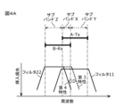
- FIG. 4A is a diagram illustrating the frequency relationship between communication band A and communication band B applied to a high-frequency circuit according to the first variation of the embodiment, and the pass characteristics of filters 11 and 22.
- communication band A is an example of a second communication band
- communication band B is an example of a first communication band.
- Communication band A and communication band B are a band combination that allows simultaneous communication. As shown in FIG. 4A, the transmission band (A-Tx) of communication band A and the reception band (B-Rx) of communication band B partially overlap in frequency.
- the reception band of communication band B is an example of a first frequency band
- the transmission band of communication band A is an example of a second frequency band.
- the reception band of communication band B includes subband X (first subband) that overlaps with the transmission band of communication band A, and subband Z (second subband) that does not overlap with the transmission band of communication band A.
- the transmission band of communication band A includes subband X (first subband) that overlaps with the reception band of communication band B, and subband Y (third subband) that does not overlap with the reception band of communication band B.
- Filter 22 is an example of a first filter, and has a passband that includes the reception band (first frequency band) of communication band B. More specifically, filter 22 varies a first passband that includes subband X and subband Z, and a second passband that includes subband Z and is narrower than the first passband. In other words, filter 22 varies a third characteristic having the first passband, and a fourth characteristic having the second passband. One end of filter 22 is connected to terminal 50d (first terminal) of switch 50 (first switch), and the other end of filter 22 is connected to the input end of low-noise amplifier 42.
- Filter 11 is an example of a second filter, and has a passband that includes the transmission band (second frequency band) of communication band A. One end of filter 11 is connected to terminal 50c (second terminal) of switch 50 (first switch), and the other end of filter 11 is connected to the input terminal of power amplifier 31.
- Switch 50 is an example of a first switch and has terminal 50a (first antenna connection terminal), terminal 50b (second antenna connection terminal), terminal 50c (second terminal), and terminal 50d (first terminal).
- the high-frequency circuit according to this modified example can execute (1) a first mode in which a transmit signal in subband Y of communication band A and a receive signal in subband Z of communication band B are simultaneously transmitted, (2) a second mode in which a transmit signal in communication band A is transmitted but a receive signal in communication band B is not transmitted, and (3) a third mode in which a receive signal in communication band B is transmitted but a transmit signal in communication band A is not transmitted.
- the filter 22 when the third mode is executed, the filter 22 is set to the first passband, so that the reception signal of the communication band B can be transmitted using the entire reception band of the communication band B. Also, when the second mode is executed, the transmission signal of the communication band A can be transmitted using the filter 11. Also, when the first mode is executed, the filter 22 is set to the second passband, so that the isolation between the reception signal of the communication band B that passes through the filter 22 and the transmission signal of the communication band A that passes through the filter 11 can be improved, and the deterioration of the reception sensitivity of the communication band B can be suppressed.
- the passband of filter 22 is variable, so that even if filter 11 and filter 22 are placed close to each other, mutual interference between the transmission signal of communication band A and the reception signal of communication band B during execution of the first mode can be suppressed, and isolation can be ensured. Therefore, a small-sized high-frequency circuit can be provided that can simultaneously transmit the transmission signal of communication band A and the reception signal of communication band B while suppressing the deterioration of isolation and reception sensitivity.
- communication band A is, for example, either band 8 for 4G-LTE or band n8 for 5G-NR
- communication band B is, for example, either band 5 for 4G-LTE or band n5 for 5G-NR.
- both the filters 11 and 22 may have variable passbands.
- the high-frequency circuit according to the second modification includes filters 11, 12, 21, and 22, a switch 50, power amplifiers 31 and 41, low-noise amplifiers 32 and 42, antenna terminals 101 and 102, high-frequency input terminals 110 and 130, and high-frequency output terminals 120 and 140.
- the high-frequency circuit according to this modification differs from the high-frequency circuit 1 according to the embodiment only in that both filters 11 and 22 are filters with variable passbands.
- FIG. 4B is a diagram illustrating the frequency relationship between communication band A and communication band B applied to the high-frequency circuit according to the second modification of the embodiment, and the pass characteristics of filters 11 and 22.
- communication band A is an example of a first communication band
- communication band B is an example of a second communication band.
- Communication band A and communication band B are a band combination that allows simultaneous communication.
- the transmission band (A-Tx) of communication band A and the reception band (B-Rx) of communication band B partially overlap in frequency.
- the transmission band of communication band A is an example of a first frequency band
- the reception band of communication band B is an example of a second frequency band.
- the transmission band of communication band A includes subband X (first subband) that overlaps with the reception band of communication band B, and subband Y (second subband) that does not overlap with the reception band of communication band B.
- the reception band of communication band B includes subband X (first subband) that overlaps with the transmission band of communication band A, and subband Z (third subband) that does not overlap with the transmission band of communication band A.
- Filter 11 is an example of a first filter, and has a passband that includes the transmission band (first frequency band) of communication band A. More specifically, filter 11 varies a first passband that includes subband X and subband Y, and a second passband that includes subband Y and is narrower than the first passband. In other words, filter 11 varies a first characteristic having a first passband, and a second characteristic having a second passband. One end of filter 11 is connected to terminal 50c (first terminal) of switch 50 (first switch), and the other end of filter 11 is connected to the output terminal of power amplifier 31.
- Filter 22 is an example of a second filter, and has a passband that includes the reception band (second frequency band) of communication band B. More specifically, filter 22 varies a third passband that includes subband X and subband Z, and a fourth passband that includes subband Z and is narrower than the third passband. In other words, filter 22 varies a third characteristic having a third passband, and a fourth characteristic having a fourth passband.
- One end of filter 22 is connected to terminal 50d (second terminal) of switch 50 (first switch), and the other end of filter 22 is connected to the input end of low-noise amplifier 42.
- the high-frequency circuit according to this modified example can execute (1) a first mode in which a transmit signal in subband Y of communication band A and a receive signal in subband Z of communication band B are simultaneously transmitted, (2) a second mode in which a transmit signal in communication band A is transmitted but a receive signal in communication band B is not transmitted, and (3) a third mode in which a receive signal in communication band B is transmitted but a transmit signal in communication band A is not transmitted.
- the filter 11 when the second mode is executed, the filter 11 is set to the first passband, so that the transmission signal of the communication band A can be transmitted using the entire transmission band of the communication band A. Furthermore, when the third mode is executed, the filter 22 can be used to transmit the reception signal of the communication band B. Furthermore, when the first mode is executed, the filter 11 is set to the second passband, and the filter 22 is set to the fourth passband, so that the mutual interference between the transmission signal of the communication band A passing through the filter 11 and the reception signal of the communication band B passing through the filter 22 can be further suppressed, improving isolation and suppressing deterioration of the reception sensitivity of the reception signal of the communication band B.
- the passbands of filters 11 and 22 are variable, so that high isolation between the transmission signal of communication band A and the reception signal of communication band B during execution of the first mode can be ensured even if filters 11 and 22 are placed close to each other. Therefore, it is possible to provide a small-sized high-frequency circuit that can simultaneously transmit the transmission signal of communication band A and the reception signal of communication band B while suppressing deterioration of isolation and reception sensitivity.
- communication band A is, for example, either band 8 for 4G-LTE or band n8 for 5G-NR
- communication band B is, for example, either band 5 for 4G-LTE or band n5 for 5G-NR.
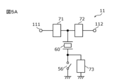
- FIG. 5A is a diagram showing a first example of the circuit configuration of a filter 11 according to an embodiment.
- FIG. 5B is a diagram showing a second example of the circuit configuration of a filter 11 according to an embodiment.
- FIG. 5C is a diagram showing a third example of the circuit configuration of a filter 11 according to an embodiment.
- the filter 11 shown in FIG. 5A includes circuit elements 71, 72, and 73, a switch 56, and an elastic wave resonator 60.
- the circuit elements 71 and 72 are connected in series on a series arm path connecting the terminals 111 and 112.
- the elastic wave resonator 60 is connected between the connection point of the circuit elements 71 and 72 and ground.
- the switch 56 is connected in series with the elastic wave resonator 60 on a parallel arm path connecting the connection point and ground.
- the circuit element 73 is connected in parallel to the switch 56.
- Each of the circuit elements 71, 72, and 73 is, for example, any one of an inductor, a capacitor, and an elastic wave resonator.
- the resonance bandwidth (frequency difference between the antiresonance frequency and the resonance frequency) of the elastic wave resonator 60 is variable depending on whether the switch 51 is conductive or non-conductive.
- the pass band of the filter 11 in this example is variable depending on whether the switch 56 is conductive or non-conductive.
- the filter 11 shown in FIG. 5B includes circuit elements 71, 72, and 73, a switch 56, and an elastic wave resonator 60.
- the circuit elements 71 and 72 are connected in series on a series arm path connecting terminals 111 and 112.
- the elastic wave resonator 60 is connected between the connection point of the circuit elements 71 and 72 and ground.
- the series connection circuit of the switch 56 and the circuit element 73 is connected in parallel to the elastic wave resonator 60.
- Each of the circuit elements 71, 72, and 73 is, for example, any one of an inductor, a capacitor, and an elastic wave resonator.
- the resonance bandwidth of the elastic wave resonator 60 is variable depending on whether the switch 56 is conductive or non-conductive.
- the passband of the filter 11 in this example is variable depending on whether the switch 56 is conductive or non-conductive.
- the filter 11 shown in FIG. 5C includes circuit elements 71 and 72, a variable circuit element 74, and an elastic wave resonator 60.
- the circuit elements 71 and 72 are connected in series on a series arm path connecting the terminals 111 and 112.
- the elastic wave resonator 60 is connected between the connection point of the circuit elements 71 and 72 and ground.
- the variable circuit element 74 is connected between the connection point of the circuit elements 71 and 72 and ground.
- Each of the circuit elements 71 and 72 is, for example, any of an inductor, a capacitor, and an elastic wave resonator.
- the variable circuit element 74 is, for example, any of a variable inductor and a variable capacitor.
- the variable circuit element 74 may be composed of an inductor, a capacitor, an elastic wave resonator, and a switch.
- the resonance bandwidth of the elastic wave resonator 60 is variable by varying the physical quantity (inductance value or capacitance value) of the variable circuit element 74.
- the pass band of the filter 11 in this example is variable by varying the physical quantity of the variable circuit element 74.
- the passband of the filter 11 may include one of the transmission band and the reception band of the communication band C (third communication band).
- the high frequency circuit according to the third modification includes filters 11, 12, 21 and 22, a switch 50, power amplifiers 31 and 41, low noise amplifiers 32 and 42, antenna terminals 101 and 102, high frequency input terminals 110 and 130, and high frequency output terminals 120 and 140.
- the high frequency circuit according to this modification differs from the high frequency circuit 1 according to the embodiment only in that the pass band of filter 11 includes the transmission band of communication band C (third communication band).
- the description of the high frequency circuit according to this modification that is the same as that of the high frequency circuit 1 according to the embodiment will be omitted, and the description will focus on the different configurations.
- FIG. 6 is a diagram illustrating the frequency relationship of communication bands A, B, and C applied to a high-frequency circuit according to the third modified embodiment, and the pass characteristics of filters 11 and 22.
- communication band A is an example of a first communication band
- communication band B is an example of a second communication band.
- Communication bands A and B are a band combination that allows simultaneous communication.
- the transmission band (A-Tx) of communication band A and the reception band (B-Rx) of communication band B partially overlap in frequency.
- the transmission band (C-Tx) of communication band C overlaps with sub-band Y of the transmission band of communication band A, but does not overlap with sub-band X.
- Filter 11 is an example of a first filter, and has a passband that includes the transmission band of communication band A (first frequency band) and the transmission band of communication band C.
- the high-frequency circuit according to variant 3 can execute (1) a first mode in which a transmission signal of subband Y of communication band A and a reception signal of subband Z of communication band B are simultaneously transmitted; (2) a second mode in which a transmission signal of communication band A is transmitted but a reception signal of communication band B is not transmitted; (3) a third mode in which a reception signal of communication band B is transmitted but a transmission signal of communication band A is not transmitted; and (4) a fourth mode in which a transmission signal of communication band C is transmitted.
- the signal quality of the transmission signal of communication band C that passes through filter 11 can be improved by setting filter 11 to the second passband.
- the transmission band of the communication band C may overlap with the sub-band X.
- the transmission signal of the communication band C can be transmitted using the entire transmission band of the communication band C by setting the filter 11 to the first passband.
- the transmission band of communication band A it is possible for the transmission band of communication band A to overlap with the reception band of communication band C, rather than the transmission band of communication band C.
- the filter 11 when transmitting a reception signal of communication band C, the filter 11 can be set to the second passband to suppress deterioration of the reception sensitivity of communication band C.
- the passband of the filter 22 may include one of the transmission band and reception band of the communication band C (third communication band).
- the quality of the transmission signal of the communication band C can be improved or the deterioration of the reception sensitivity of the communication band C can be suppressed by setting the filter 22 to the third passband or the fourth passband.
- the passband of filter 11 or the passband of filter 22 may include one of the transmission band and reception band of communication band C (third communication band).
- the passband of filter 11 or the passband of filter 22 may include one of the transmission band and reception band of communication band C (third communication band).
- the quality of the transmission signal of communication band C can be improved, or the deterioration of the reception sensitivity of communication band C can be suppressed.
- communication band A is, for example, either band 8 for 4G-LTE or band n8 for 5G-NR
- communication band B is, for example, either band 5 for 4G-LTE or band n5 for 5G-NR
- communication band C is, for example, band n106 for 5G-NR (transmission band: 896-901 MHz, reception band: 935-940 MHz).
- FIG. 7A is a circuit diagram showing a first connection state of the high-frequency circuit 1A according to Modification 4.
- FIG. 7B is a diagram showing an example of the frequency relationship of each communication band applied to the high-frequency circuit 1A according to Modification 4, and the pass characteristics of each filter in the first connection state.
- FIG. 8A is a circuit diagram showing a second connection state of the high-frequency circuit 1A according to Modification 4.
- FIG. 8B is a diagram showing an example of the frequency relationship of each communication band applied to the high-frequency circuit 1A according to Modification 4, and the pass characteristics of each filter in the second connection state.
- the high-frequency circuit 1A according to the fourth modification includes filters 11, 12, 13, 21, and 22, a switch 51, a matching circuit 75, power amplifiers 31, 33, and 41, low-noise amplifiers 32 and 42, antenna terminals 101 and 102, high-frequency input terminals 110, 130, and 150, and high-frequency output terminals 120 and 140.
- the high-frequency circuit 1A according to this modification differs from the high-frequency circuit 1 according to the embodiment in that a circuit element for transmitting signals of communication band D is added.
- a description of the configuration of the high-frequency circuit 1A according to this modification that is the same as that of the high-frequency circuit 1 according to the embodiment will be omitted, and the different configuration will be mainly described.
- Antenna terminal 101 is connected to antenna 2a and terminal 51a of switch 51.
- Antenna terminal 102 is connected to antenna 2b and terminal 51b of switch 51.
- High frequency input terminal 150 is connected to power amplifier 33 and is a terminal for receiving a transmission signal.
- communication band A is an example of a first communication band
- communication band B is an example of a second communication band
- communication band D is an example of a fourth communication band.
- Communication band A, communication band B, and communication band D are a band combination that allows simultaneous communication.
- the transmission band (A-Tx) of communication band A and the reception band (B-Rx) of communication band B partially overlap in frequency.
- the transmission band (D-Tx) of communication band D does not overlap in frequency with the transmission band (A-Tx) of communication band A and the reception band (B-Rx) of communication band B.
- the transmission band of communication band A is an example of a first frequency band
- the reception band of communication band B is an example of a second frequency band
- the transmission band of communication band D is an example of a third frequency band.
- the transmission band of communication band A includes subband X (first subband) that overlaps with the reception band of communication band B, and subband Y (second subband) that does not overlap with the reception band of communication band B.
- the reception band of communication band B includes subband X (first subband) that overlaps with the transmission band of communication band A, and subband Z (third subband) that does not overlap with the transmission band of communication band A.
- Filter 11 is an example of a first filter, and varies a first passband including subband X and subband Y, and a second passband including subband Y and narrower than the first passband. In other words, filter 11 varies a first characteristic having a first passband, and a second characteristic having a second passband.
- One end of filter 11 is connected to terminal 51c (first terminal) of switch 51 (first switch), and the other end of filter 11 is connected to the output terminal of power amplifier 31.
- Filter 22 is an example of a second filter, and has a passband that includes the reception band (second frequency band) of communication band B.
- One end of filter 22 is connected to terminal 51d (second terminal) of switch 51 (first switch), and the other end of filter 22 is connected to the input terminal of low-noise amplifier 42.
- the filter 12 has a pass band that includes the reception band of the communication band A.
- One end of the filter 12 is connected to the terminal 51c of the switch 51, and the other end of the filter 12 is connected to the input terminal of the low-noise amplifier 32.
- the filter 21 has a pass band that includes the transmission band of the communication band B. One end of the filter 21 is connected to the terminal 51d of the switch 51, and the other end of the filter 21 is connected to the output terminal of the power amplifier 41.
- Filter 13 is an example of a third filter, and has a passband that includes the transmission band (third frequency band) of communication band D.
- One end of filter 13 is connected to terminal 51c (first terminal) of switch 51 (first switch), and the other end of filter 13 is connected to the output terminal of power amplifier 33.
- Matching circuit 75 is an example of an impedance matching circuit, and is connected between terminal 51e and ground.
- Matching circuit 75 is composed of, for example, at least one of an inductor, a capacitor, and an elastic wave resonator.
- Switch 51 is an example of a first switch and a second switch, and has terminal 51a (first antenna connection terminal), terminal 51b (second antenna connection terminal), terminal 51c (first terminal), terminal 51d (second terminal), and terminal 51e.
- Terminals 51a, 51b, 51c, and 51d of switch 51 constitute a first switch
- terminals 51a and 51e of switch 51 constitute a second switch.
- Switch 51 switches between connection and non-connection between terminals 51a and 51c, between connection and non-connection between terminals 51a and 51d, between connection and non-connection between terminals 51b and 51c, and between connection and non-connection between terminals 51b and 51c, and between connection and non-connection between terminals 51b and 51d.
- Switch 51 also switches between connection and non-connection between terminals 51a and 51e.
- switch 51 may be a switch circuit composed of a first switch having terminals 51a, 51b, 51c, and 51d, and a second switch having terminals 51a and 51e.
- Terminal 51a is connected to antenna terminal 101
- terminal 51b is connected to antenna terminal 102
- terminal 51c is connected to filters 11, 12 and 13
- terminal 51d is connected to filters 21 and 22,
- terminal 51e is connected to matching circuit 75.
- switch 51 switches between connection and disconnection between antenna 2a and filters 11 to 13, between connection and disconnection between antenna 2a and filters 21 and 22, between connection and disconnection between antenna 2b and filters 11 to 13, between connection and disconnection between antenna 2b and filters 21 and 22, and between connection and disconnection between antenna 2a and matching circuit 75.
- switch 51 may switch between connection and disconnection between terminal 51c and terminal 51e. In this case, instead of switching between connecting and disconnecting the antenna 2a and the matching circuit 75, the switch 51 switches between connecting and disconnecting the filters 11 to 13 and the matching circuit 75.
- the output terminal of the power amplifier 33 is connected to the filter 13, and the input terminal is connected to the radio frequency input terminal 150.
- the power amplifier 33 amplifies the transmission signal of the communication band D input from the radio frequency input terminal 150.
- the high frequency circuit 1A can execute (1) a fifth mode in which a transmission signal of subband Y of communication band A, a reception signal of subband Z of communication band B, and a transmission signal of communication band D are simultaneously transmitted, (2) a sixth mode in which a transmission signal of communication band A and a transmission signal of communication band D are simultaneously transmitted, but a reception signal of communication band B is not transmitted, and (3) a third mode in which a reception signal of communication band B is transmitted, but a transmission signal of communication band A is not transmitted.
- the filter 11 is set to the first passband, so that the transmission signal of communication band A can be transmitted using the entire transmission band of communication band A.
- terminal 51a is connected to terminal 51c, and terminal 51d is not connected to terminals 51a and 51b. Furthermore, terminal 51a is not connected to terminal 51e.
- the filter 11 when the fifth mode is executed, the filter 11 is set to the second passband. At this time, terminals 51a and 51c are connected, and terminals 51b and 51d are connected. This improves the isolation between the transmission signal of communication band A that passes through filter 11 and the reception signal of communication band B that passes through filter 22, and suppresses deterioration of the reception sensitivity of communication band B.
- the passband of filter 11 is changed from the first passband to the second passband, and the attenuation characteristics of filter 11 in the transmission band of communication band D change (the attenuation characteristics are shown by the dashed line in Fig. 8B (matching circuit 75 not connected)).
- matching circuit 75 is connected to filters 11, 12, and 13 by further connecting terminals 51a and 51e. This makes it possible to adjust the attenuation characteristics of filter 11 when the passband changes, and improves the attenuation characteristics of filter 11 in the transmission band of communication band D (the attenuation characteristics are shown by the solid line in Fig. 8B (matching circuit 75 connected)).
- the communication band A is, for example, either band 8 for 4G-LTE or band n8 for 5G-NR
- the communication band B is, for example, either band 5 for 4G-LTE or band n5 for 5G-NR
- the communication band D is, for example, either band 28 (transmit band: 703-748MHz, receive band: 758-803MHz) and band 12 (transmit band: 699-716MHz, receive band: 729-746MHz) for 4G-LTE
- band n28 transmit band: 703-748MHz, receive band: 758-803MHz
- band n12 transmit band: 699-716MHz, receive band: 729-746MHz for 5G-NR.
- FIG. 9A is a circuit diagram of a high-frequency circuit 1B and a diver circuit 5B according to Modification 5.
- the high-frequency circuit 1B is an example of a high-frequency circuit according to the present invention, and is connected to the diver circuit 5B.
- the high-frequency circuit 1B according to this modification includes filters 11, 12, 13, 21, 22, and 23, a switch 52, and a matching circuit 75.
- Filter 11 is an example of a first filter and has a passband that includes the transmission band of band n8 (communication band A) for 5G-NR.
- Band n8 for 5G-NR is an example of a first communication band.
- Filter 12 has a passband that includes the reception band of band n8 for 5G-NR.
- Filter 21 has a passband that includes the transmission band of band n5 (communication band B) for 5G-NR and the transmission band of band n26 (transmission band: 814-849 MHz, reception band: 859-894 MHz).
- Band n5 for 5G-NR is an example of a second communication band.
- Filter 22 is an example of a second filter and has a passband that includes the reception band of band n5 and the reception band of band n26 for 5G-NR.
- Filter 13 has a passband that includes the transmission band of band n28 (communication band D) for 5G-NR or the transmission band of band n12 (communication band D) for 5G-NR.
- Filter 23 has a passband that includes the receiving band of band n28 for 5G-NR or the receiving band of band n12 for 5G-NR.
- band n8 and band n5 are a band combination that allows simultaneous communication.
- the transmission band of band n8 and the reception band of band n5 partially overlap in frequency.
- the transmission band of band n8 is an example of a first frequency band
- the reception band of band n5 is an example of a second frequency band.
- the transmission band of band n8 includes subband X (first subband) that overlaps with the reception band of band n5, and subband Y (second subband) that does not overlap with the reception band of band n5.
- the reception band of band n5 includes subband X (first subband) that overlaps with the transmission band of band n8, and subband Z (third subband) that does not overlap with the transmission band of band n8.
- Filter 11 varies between a first passband that includes subband X and subband Y, and a second passband that includes subband Y and is narrower than the first passband.
- One end of filter 11 is connected to a first selection terminal of switch 52.
- Filter 22 has a passband that includes subband X and subband Z. One end of filter 22 is connected to the second selection terminal of switch 52.
- Matching circuit 75 is an example of an impedance matching circuit, and is connected between the third selection terminal of switch 52 and ground.
- Switch 52 is an example of a first switch, and switches between the connection and disconnection of the first antenna and filters 11 and 12, between the connection and disconnection of the first antenna and filters 21 and 22, between the connection and disconnection of the first antenna and filters 13 and 23, between the connection and disconnection of the first antenna and diverter circuit 5B, between the connection and disconnection of the second antenna and filters 11 and 12, between the connection and disconnection of the second antenna and filters 21 and 22, between the connection and disconnection of the second antenna and filters 13 and 23, between the connection and disconnection of the second antenna and diverter circuit 5B, and between the connection and disconnection of the second antenna and matching circuit 75.
- the diver circuit 5B also includes filters 82 and 92 and a switch 53.
- Filter 92 has a passband that includes the reception band of band n5 and the reception band of band n26 for 5G-NR.
- Filter 82 has a passband that includes the receive band of band n8 for 5G-NR.
- the switch 53 switches between the connection and disconnection between the third antenna and the filter 92, between the connection and disconnection between the third antenna and the filter 82, between the connection and disconnection between the third antenna and the high-frequency circuit 1B, between the connection and disconnection between the fourth antenna and the filter 92, between the connection and disconnection between the fourth antenna and the filter 82, and between the connection and disconnection between the fourth antenna and the high-frequency circuit 1B.
- the high frequency circuit 1B and the diver circuit 5B can execute (1) a first mode in which a transmission signal of sub-band Y of communication band A and a reception signal of sub-band Z of communication band B are simultaneously transmitted, (2) a second mode in which a transmission signal of communication band A is transmitted but a reception signal of communication band B is not transmitted, and (3) a third mode in which a reception signal of communication band B is transmitted but a transmission signal of communication band A is not transmitted.
- the filter 11 when the second mode is executed, the filter 11 is set to the first passband, so that the transmission signal of the communication band A can be transmitted using the entire transmission band of the communication band A. Also, when the second mode is executed, the filter 11 is connected to the first antenna or the second antenna.
- the received signal of the communication band B can be transmitted using the filter 22.
- the filter 22 is connected to the first antenna or the second antenna.
- the filter 11 When the first mode is executed, the filter 11 is set to the second passband, and as shown in FIG. 9A, the filter 11 is connected to the second antenna, and the filter 22 is connected to the first antenna.
- the first antenna or the second antenna may also be connected to a matching circuit 75. This improves the isolation between the transmission signal of communication band A that passes through the filter 11 and the reception signal of communication band B that passes through the filter 22, and suppresses deterioration of the reception sensitivity of communication band B.
- the filter 82 may be connected to the fourth antenna, and the filter 92 may be connected to the third antenna. This allows the reception signal of communication band A and the reception signal of communication band B to be received by the diver circuit 5B.
- 9B is a circuit configuration diagram of a high-frequency circuit 1C and a primary circuit 5C according to Modification 6.
- the high-frequency circuit 1C is an example of a high-frequency circuit according to the present invention, and is connected to the primary circuit 5C.
- the high-frequency circuit 1C according to this modification includes filters 11, 12, 22, and 23, a switch 55, and a matching circuit 75.
- Filter 11 is an example of a first filter and has a passband that includes the transmission band of band n8 (communication band A) for 5G-NR.
- Band n8 for 5G-NR is an example of a first communication band.
- Filter 12 has a passband that includes the reception band of band n8 for 5G-NR.
- Filter 22 is an example of a second filter and has a passband that includes the reception band of band n5 (communication band B) for 5G-NR and the reception band of band n26.
- Filter 23 has a passband that includes the reception band of band n28 (communication band D) for 5G-NR or the reception band of band n12 for 5G-NR.
- band n8 and band n5 are a band combination that allows simultaneous communication.
- the transmission band of band n8 and the reception band of band n5 partially overlap in frequency.
- the transmission band of band n8 is an example of a first frequency band
- the reception band of band n5 is an example of a second frequency band.
- the transmission band of band n8 includes subband X (first subband) that overlaps with the reception band of band n5, and subband Y (second subband) that does not overlap with the reception band of band n5.
- the reception band of band n5 includes subband X (first subband) that overlaps with the transmission band of band n8, and subband Z (third subband) that does not overlap with the transmission band of band n8.
- Filter 11 varies between a first passband that includes subband X and subband Y, and a second passband that includes subband Y and is narrower than the first passband.
- One end of filter 11 is connected to a first selection terminal of switch 55.
- Filter 22 has a passband that includes subband X and subband Z. One end of filter 22 is connected to the second selection terminal of switch 55.
- the matching circuit 75 is an example of an impedance matching circuit, and is connected between the third selection terminal of the switch 55 and ground.
- Switch 55 is an example of a first switch, and switches between the connection and disconnection of the first antenna and filters 11 and 12, between the connection and disconnection of the first antenna and filter 22, between the connection and disconnection of the first antenna and filter 23, between the connection and disconnection of the first antenna and primary circuit 5C, between the connection and disconnection of the second antenna and filters 11 and 12, between the connection and disconnection of the second antenna and filter 22, between the connection and disconnection of the second antenna and filter 23, between the connection and disconnection of the second antenna and primary circuit 5C, and between the connection and disconnection of the second antenna and matching circuit 75.
- the primary circuit 5C includes filters 82, 83, 84, 91, and 92, and a switch 54.
- Filter 82 has a passband that includes the receive band of band n8 for 5G-NR.
- Filter 83 has a passband that includes the transmission band of band n28 for 5G-NR or the transmission band of band n12 for 5G-NR.
- Filter 84 has a passband that includes the receiving band of band n28 for 5G-NR or the receiving band of band n12 for 5G-NR.
- Filter 91 has a passband that includes the transmission band of band n5 and the transmission band of band n26 for 5G-NR.
- Filter 92 has a passband that includes the reception band of band n5 and the reception band of band n26 for 5G-NR.
- Switch 54 switches between connection and disconnection between the third antenna and filter 82, between connection and disconnection between the third antenna and filters 83 and 84, between connection and disconnection between the third antenna and filters 91 and 92, between connection and disconnection between the third antenna and high-frequency circuit 1C, between connection and disconnection between the fourth antenna and filter 82, between connection and disconnection between the fourth antenna and filters 83 and 84, between connection and disconnection between the fourth antenna and filters 91 and 92, and between connection and disconnection between the fourth antenna and high-frequency circuit 1C.
- the high-frequency circuit 1C and the primary circuit 5C can execute (1) a first mode in which a transmission signal of subband Y of communication band A and a reception signal of subband Z of communication band B are simultaneously transmitted, (2) a second mode in which a transmission signal of communication band A is transmitted but a reception signal of communication band B is not transmitted, and (3) a third mode in which a reception signal of communication band B is transmitted but a transmission signal of communication band A is not transmitted.
- the filter 11 when the second mode is executed, the filter 11 is set to the first passband, so that the transmission signal of the communication band A can be transmitted using the entire transmission band of the communication band A. Also, when the second mode is executed, the filter 11 is connected to the first antenna or the second antenna.
- the received signal of the communication band B can be transmitted using the filter 22.
- the filter 22 is connected to the first antenna or the second antenna.
- filter 11 When the first mode is executed, filter 11 is set to the second passband, and as shown in FIG. 9B, filter 11 is connected to the second antenna, and filter 22 is connected to the first antenna. Also, the first antenna or the second antenna may be connected to matching circuit 75. This improves the isolation between the transmission signal of communication band A that passes through filter 11 and the reception signal of communication band B that passes through filter 22, and suppresses deterioration of the reception sensitivity of communication band B.
- filter 82 may be connected to the fourth antenna, and filters 91 and 92 may be connected to the third antenna. This allows the received signal of communication band A and the received signal of communication band B to be transmitted simultaneously by primary circuit 5C.
- the high-frequency circuit 1 includes the filter 11 having a pass band including a first frequency band which is one of the transmission band and reception band of the communication band A, and the filter 22 having a pass band including a second frequency band which is the other of the transmission band and reception band of the communication band B, the communication band A and the communication band B are a band combination enabling simultaneous communication, the first frequency band includes a sub-band X which overlaps with the second frequency band and a sub-band Y which does not overlap with the second frequency band, the second frequency band includes sub-band X and a sub-band Z which does not overlap with the first frequency band, and the pass band of the filter 11 is variable to a first pass band which includes sub-band X and sub-band Y, and a second pass band which includes sub-band Y and is narrower than the first pass band.
- the signal when a signal in the first frequency band is transmitted alone, the signal can be transmitted using the entire bandwidth of the first frequency band by setting filter 11 to the first passband.
- the isolation between the two signals can be improved by setting filter 11 to the second passband, so that deterioration of reception sensitivity when signals in subband Y and signals in subband Z are transmitted simultaneously can be suppressed.
- a small-sized high-frequency circuit 1 can be provided that can simultaneously transmit signals in communication band A and communication band B while suppressing deterioration of isolation and reception sensitivity.
- the passband of the filter 11 becomes the first passband, and when the first frequency band signal and the second frequency band signal are transmitted simultaneously, the passband of the filter 11 becomes the second passband.
- the first frequency band is the transmission band of communication band A
- the second frequency band is the reception band of communication band B.
- the transmission signal when a transmission signal of communication band A is transmitted alone, the transmission signal can be transmitted using the entire bandwidth of the transmission band of communication band A by setting filter 11 to the first pass band.
- a transmission signal of communication band A when a transmission signal of communication band A is passed through filter 11 and a reception signal of communication band B is passed through filter 22 for simultaneous transmission, even if filter 11 and filter 22 are arranged close to each other, isolation between the two signals can be improved by setting filter 11 to the second pass band, so that deterioration of reception sensitivity can be suppressed when a transmission signal of communication band A and a reception signal of communication band B are transmitted simultaneously. Therefore, a small-sized high-frequency circuit 1 can be provided that can simultaneously transmit a transmission signal of communication band A and a reception signal of communication band B while suppressing deterioration of isolation and reception sensitivity.
- the first frequency band is the receiving band of communication band B
- the second frequency band is the transmitting band of communication band A
- filter 22 varies between a first passband that includes subband X and subband Z, and a second passband that includes subband Z and is narrower than the first passband.
- the received signal of communication band B when the received signal of communication band B is transmitted alone, the received signal can be transmitted using the entire bandwidth of the received band of communication band B by setting filter 22 to the first passband.
- the received signal of communication band B when the received signal of communication band B is passed through filter 22 and the transmitted signal of communication band A is passed through filter 11 for simultaneous transmission, the isolation of both signals can be improved by setting filter 22 to the second passband, thereby suppressing deterioration of the receiving sensitivity of communication band B when transmitted simultaneously.
- subband Y overlaps with at least one of the transmission band and reception band of communication band C
- subband X does not overlap with at least one of the transmission band and reception band of communication band C
- the passband of filter 11 becomes the second passband
- the quality of the signal of communication band C passing through filter 11 can be improved by setting filter 11 to the second passband.
- communication band C is band n106 for 5G-NR.
- filter 11 varies a first passband including subband X and subband Y and a second passband including subband Y and narrower than the first passband
- filter 22 varies a third passband including subband X and subband Z and a fourth passband including subband Z and narrower than the third passband.
- the passbands of filters 11 and 22 are variable, so that even if filters 11 and 22 are placed close to each other, isolation between signals in communication band A and signals in communication band B can be ensured. This makes it possible to suppress deterioration of reception sensitivity when signals in subband Y and subband Z are transmitted simultaneously.
- the passband of filter 11 when only the first frequency band signal of the first frequency band signal and the second frequency band signal is transmitted, the passband of filter 11 is the first passband, when only the second frequency band signal of the first frequency band signal and the second frequency band signal is transmitted, the passband of filter 22 is the third passband, and when the first frequency band signal and the second frequency band signal are transmitted simultaneously, the passband of filter 11 is the second passband and the passband of filter 22 is the fourth passband.
- the high frequency circuit 1 further includes a switch 50 having a terminal 50a connected to an antenna, a terminal 50b connected to an antenna, a terminal 50c connected to the filter 11, and a terminal 50d connected to the filter 22.
- the terminal 50c when transmitting only the first frequency band signal out of the first frequency band signal and the second frequency band signal, the terminal 50c is connected to the terminal 50a and the terminal 50d is connected to neither the terminal 50a nor the terminal 50b, and when transmitting the first frequency band signal and the second frequency band signal simultaneously, the terminal 50c is connected to the terminal 50a and the terminal 50d is connected to the terminal 50b.
- the high-frequency circuit 1A according to the fourth modification further includes a filter 13 connected to the terminal 51c and having a passband including a third frequency band, which is one of the transmission band and reception band of the communication band D, a matching circuit 75, and a switch 51 for switching between connection and disconnection between the terminal 51c and the matching circuit 75, and the third frequency band does not overlap with the first frequency band and the second frequency band.
- the high frequency circuit 1A can execute (1) a fifth mode in which signals of communication band A, communication band B, and communication band D are transmitted simultaneously, (2) a sixth mode in which signals of communication band A and communication band D are transmitted simultaneously, but signals of communication band B are not transmitted, and (3) a third mode in which signals of communication band B are transmitted, but signals of communication band A are not transmitted.
- the matching circuit 75 can be switched between connected and disconnected when switching between modes, making it possible to improve the attenuation characteristics of the filter 11 in the communication band D.
- terminal 51c when transmitting only the first frequency band signal out of the first frequency band signal and the second frequency band signal, terminal 51c is connected to terminal 51a, terminal 51d is connected to neither terminal 51a nor 51b, and matching circuit 75 is connected to terminals 51c and 51e, whereas when transmitting the first frequency band signal and the second frequency band signal simultaneously, terminal 51c is connected to terminal 51a, terminal 51d is connected to terminal 51b, and matching circuit 75 is connected to terminal 51c.
- the passband of the filter 11 When switching from the sixth mode to the fifth mode, the passband of the filter 11 is changed from the first passband to the second passband, thereby changing the attenuation characteristics of the filter 11 in the communication band D.
- a matching circuit 75 when switching to the fifth mode, by further connecting a matching circuit 75 to the filter 11, it is possible to adjust the attenuation characteristics of the filter 11 when the passband is changed, and to improve the attenuation characteristics of the filter 11 in the communication band D. Therefore, in the simultaneous transmission of signals of two communication bands A and B, which have partially overlapping frequency bands, it is possible to suppress deterioration of isolation and receiving sensitivity, and it is possible to transmit the communication band D, which is transmitted simultaneously with the communication bands A and B, with low loss.
- the communication band D is either band 28 or band 12 for 4G-LTE, or band n28 or band n12 for 5G-NR.
- a first switch of the SPDT type is provided that has an antenna connection terminal, a first terminal connected to the filter 11, and a second terminal connected to the filter 22.
- the first terminal when transmitting only the first frequency band signal out of the first frequency band signal and the second frequency band signal, the first terminal is connected to the antenna connection terminal and the second terminal is not connected to the antenna connection terminal, and when transmitting the first frequency band signal and the second frequency band signal simultaneously, the first terminal is connected to the antenna connection terminal and the second terminal is connected to the antenna connection terminal.
- the communication band A is either band 8 for 4G-LTE or band n8 for 5G-NR
- the communication band B is either band 5 for 4G-LTE or band n5 for 5G-NR.
- the communication device 4 also includes an RFIC 3 that processes high-frequency signals, and a high-frequency circuit 1 that transmits high-frequency signals between the RFIC 3 and the antennas 2a and 2b.
- the effects of the high-frequency circuit 1 can be realized in the communication device 4.
- the high-frequency circuit and communication device according to the present invention have been described above based on the embodiments and modifications, the high-frequency circuit and communication device according to the present invention are not limited to the above-mentioned embodiments and modifications.
- the present invention also includes other embodiments realized by combining any of the components in the above-mentioned embodiments and modifications, modifications obtained by applying various modifications to the above-mentioned embodiments and modifications that would come to mind by a person skilled in the art without departing from the spirit of the present invention, and various devices incorporating the above-mentioned high-frequency circuit and communication device.
- circuit elements and wiring etc. may be inserted between the paths connecting the circuit elements and signal paths shown in the drawings.
- a cellular band for 5G-NR or LTE is used, but a communication band for another radio access technology may be used in addition to or instead of 5G-NR or LTE.
- a communication band for a wireless local area network may be used.
- a first filter having a passband that includes a first frequency band, the first frequency band being one of a transmit band and a receive band of a first communications band; a second filter having a passband that includes a second frequency band that is the other of the transmission band and the reception band of the second communications band; the first communication band and the second communication band are a band combination capable of simultaneous communication, the first frequency band includes a first sub-band that overlaps with the second frequency band and a second sub-band that does not overlap with the second frequency band; the second frequency band includes the first sub-band and a third sub-band that does not overlap with the first communications band;
- a high-frequency circuit wherein the passband of the first filter is variable to a first passband including the first subband and the second subband, and a second passband including the second subband and narrower than the first passband.
- the pass band of the first filter is the first pass band
- the first frequency band is a transmission band of the first communications band;
- the first frequency band is a reception band of the first communication band;
- the second subband overlaps with at least one of a transmission band and a reception band of a third communications band; the first sub-band does not overlap with at least one of a transmission band and a reception band of the third communications band;
- the high-frequency circuit according to any one of ⁇ 1> to ⁇ 4>, wherein, when transmitting at least one signal of a transmission band and a reception band of the third communication band, a pass band of the first filter becomes the second pass band.
- ⁇ 6> The high-frequency circuit according to ⁇ 5>, wherein the third communication band is band n106 for 5G-NR.
- ⁇ 7> The high-frequency circuit according to any one of ⁇ 1> to ⁇ 6>, wherein the second filter varies a third passband including the first subband and the third subband, and a fourth passband including the third subband and narrower than the third passband.
- ⁇ 8> When transmitting only the first frequency band signal of the first frequency band signal and the second frequency band signal, the pass band of the first filter becomes the first pass band, When transmitting only the second frequency band signal of the first frequency band signal and the second frequency band signal, the pass band of the second filter becomes the third pass band,
- the high-frequency circuit according to ⁇ 7> wherein, when a signal of the first frequency band and a signal of the second frequency band are simultaneously transmitted, a pass band of the first filter is the second pass band, and a pass band of the second filter is the fourth pass band.
- the high-frequency circuit according to any one of ⁇ 1> to ⁇ 8>, comprising a first switch having a first antenna connecting terminal, a second antenna connecting terminal, a first terminal connected to the first filter, and a second terminal connected to the second filter.
- ⁇ 10> when transmitting only the first frequency band signal of the first frequency band signal and the second frequency band signal, the first terminal is connected to one of the first antenna connecting terminal and the second antenna connecting terminal, and the second terminal is connected to neither the first antenna connecting terminal nor the second antenna connecting terminal,
- the high-frequency circuit according to ⁇ 9> wherein, when a signal of the first frequency band and a signal of the second frequency band are simultaneously transmitted, the first terminal is connected to the first antenna connection terminal or the second antenna connection terminal, and the second terminal is connected to the first antenna connection terminal or the second antenna connection terminal.
- a third filter connected to the first terminal and having a passband that includes a third frequency band, the third frequency band being one of a transmit band and a receive band of a fourth communications band;
- An impedance matching circuit An impedance matching circuit; a second switch that switches between connection and disconnection between the first terminal and the impedance matching circuit, The high-frequency circuit according to ⁇ 9> or ⁇ 10>, wherein the third frequency band does not overlap with the first frequency band and the second frequency band.
- ⁇ 12> when transmitting only the first frequency band signal of the first frequency band signal and the second frequency band signal, the first terminal is connected to one of the first antenna connecting terminal and the second antenna connecting terminal, the second terminal is connected to neither the first antenna connecting terminal nor the second antenna connecting terminal, and the impedance matching circuit is not connected to the first terminal,
- the high-frequency circuit according to ⁇ 11> wherein, when a signal in the first frequency band and a signal in the second frequency band are simultaneously transmitted, the first terminal is connected to the first antenna connection terminal or the second antenna connection terminal, the second terminal is connected to the first antenna connection terminal or the second antenna connection terminal, and the impedance matching circuit is connected to the first terminal.
- the fourth communication band is any one of band 28 and band 12 for 4G-LTE, and band n28 and band n12 for 5G-NR.
- the high-frequency circuit according to any one of ⁇ 1> to ⁇ 8> further comprising a first switch having an antenna connection terminal, a first terminal connected to the first filter, and a second terminal connected to the second filter.
- ⁇ 15> When transmitting only the first frequency band signal among the first frequency band signal and the second frequency band signal, the first terminal is connected to the antenna connection terminal and the second terminal is not connected to the antenna connection terminal;
- the high-frequency circuit according to ⁇ 14> wherein, when a signal of the first frequency band and a signal of the second frequency band are simultaneously transmitted, the first terminal is connected to the antenna connection terminal, and the second terminal is connected to the antenna connection terminal.
- a third filter connected to the first terminal and having a passband that includes a third frequency band, the third frequency band being one of a transmit band and a receive band of a fourth communications band;
- An impedance matching circuit An impedance matching circuit; a second switch that switches between connection and disconnection between the first terminal and the impedance matching circuit, The high-frequency circuit according to ⁇ 14> or ⁇ 15>, wherein the third frequency band does not overlap with the first frequency band and the second frequency band.
- ⁇ 17> when transmitting only the first frequency band signal of the first frequency band signal and the second frequency band signal, the first terminal is connected to the antenna connection terminal, the second terminal is not connected to the antenna connection terminal, and the impedance matching circuit is not connected to the first terminal;
- the high-frequency circuit according to ⁇ 16> wherein, when a signal in the first frequency band and a signal in the second frequency band are simultaneously transmitted, the first terminal is connected to the antenna connection terminal, the second terminal is connected to the antenna connection terminal, and the impedance matching circuit is connected to the first terminal.
- the fourth communication band is any one of band 28 and band 12 for 4G-LTE, and band n28 and band n12 for 5G-NR.
- the first communication band is either band 8 for 4G-LTE or band n8 for 5G-NR;
- the radio frequency circuit according to any one of ⁇ 1> to ⁇ 18>, wherein the second communication band is either band 5 for 4G-LTE or band n5 for 5G-NR.
- a signal processing circuit for processing a high frequency signal A communication device comprising: a high-frequency circuit according to any one of ⁇ 1> to ⁇ 19>, which transmits the high-frequency signal between the signal processing circuit and an antenna.
- the present invention can be widely used as a high-frequency circuit placed in the front end of communication devices such as mobile phones.
Landscapes
- Engineering & Computer Science (AREA)
- Computer Networks & Wireless Communication (AREA)
- Signal Processing (AREA)
- Transceivers (AREA)
Abstract
Un circuit haute fréquence (1) comprend : un filtre (11) ayant une largeur de bande passante comprenant une bande de transmission d'une bande de communication A ; et un filtre (22) ayant une largeur de bande passante comprenant une bande de réception d'une bande de communication B. La bande de communication A et la bande de communication B sont une combinaison de bandes capable de communication simultanée. La bande de transmission de la bande de communication A comprend une sous-bande X chevauchant la bande de réception de la bande de communication B et une sous-bande Y ne chevauchant pas la bande de réception de la bande de communication B. La bande de réception de la bande de communication B comprend la sous-bande X et une sous-bande Z ne chevauchant pas la bande de transmission de la bande de communication A. La largeur de bande passante du filtre (11) est variable à une première largeur de bande passante comprenant la sous-bande X et la sous-bande Y et à une deuxième largeur de bande passante qui comprend la sous-bande Y et qui est plus étroite que la première largeur de bande passante.
Priority Applications (1)
| Application Number | Priority Date | Filing Date | Title |
|---|---|---|---|
| US19/412,880 US20260095200A1 (en) | 2023-06-16 | 2025-12-09 | Radio-frequency circuit and communication device |
Applications Claiming Priority (2)
| Application Number | Priority Date | Filing Date | Title |
|---|---|---|---|
| JP2023-099393 | 2023-06-16 | ||
| JP2023099393 | 2023-06-16 |
Related Child Applications (1)
| Application Number | Title | Priority Date | Filing Date |
|---|---|---|---|
| US19/412,880 Continuation US20260095200A1 (en) | 2023-06-16 | 2025-12-09 | Radio-frequency circuit and communication device |
Publications (1)
| Publication Number | Publication Date |
|---|---|
| WO2024257419A1 true WO2024257419A1 (fr) | 2024-12-19 |
Family
ID=93851772
Family Applications (1)
| Application Number | Title | Priority Date | Filing Date |
|---|---|---|---|
| PCT/JP2024/008975 Ceased WO2024257419A1 (fr) | 2023-06-16 | 2024-03-08 | Circuit haute fréquence et dispositif de communication |
Country Status (2)
| Country | Link |
|---|---|
| US (1) | US20260095200A1 (fr) |
| WO (1) | WO2024257419A1 (fr) |
Citations (2)
| Publication number | Priority date | Publication date | Assignee | Title |
|---|---|---|---|---|
| WO2018037967A1 (fr) * | 2016-08-23 | 2018-03-01 | 株式会社村田製作所 | Dispositif de filtrage, circuit frontal à haute fréquence, et dispositif de communication |
| WO2022044580A1 (fr) * | 2020-08-28 | 2022-03-03 | 株式会社村田製作所 | Circuit haute-fréquence et dispositif de communication |
-
2024
- 2024-03-08 WO PCT/JP2024/008975 patent/WO2024257419A1/fr not_active Ceased
-
2025
- 2025-12-09 US US19/412,880 patent/US20260095200A1/en active Pending
Patent Citations (2)
| Publication number | Priority date | Publication date | Assignee | Title |
|---|---|---|---|---|
| WO2018037967A1 (fr) * | 2016-08-23 | 2018-03-01 | 株式会社村田製作所 | Dispositif de filtrage, circuit frontal à haute fréquence, et dispositif de communication |
| WO2022044580A1 (fr) * | 2020-08-28 | 2022-03-03 | 株式会社村田製作所 | Circuit haute-fréquence et dispositif de communication |
Also Published As
| Publication number | Publication date |
|---|---|
| US20260095200A1 (en) | 2026-04-02 |
Similar Documents
| Publication | Publication Date | Title |
|---|---|---|
| KR102140190B1 (ko) | 스위칭 유닛을 구비한 디바이스 및 그 애플리케이션 | |
| US10277191B2 (en) | Composite filter apparatus, high-frequency front end circuit, and communication apparatus | |
| CN213937873U (zh) | 高频模块和通信装置 | |
| US12088538B2 (en) | Radio frequency module and communication device | |
| EP1532745A1 (fr) | Module a haute frequence | |
| US11539381B2 (en) | Radio frequency circuit, antenna module, and communication device | |
| US11121694B2 (en) | Multiplexer | |
| JP2020167445A (ja) | フロントエンド回路および通信装置 | |
| JP2020205477A (ja) | マルチプレクサおよび通信装置 | |
| WO2019187773A1 (fr) | Circuit frontal haute fréquence et dispositif de communication | |
| JP2008522533A (ja) | 分散型ダイプレクサ | |
| WO2022145128A1 (fr) | Circuit haute fréquence et dispositif de communication | |
| US11881844B2 (en) | Multiplexer | |
| WO2022044580A1 (fr) | Circuit haute-fréquence et dispositif de communication | |
| US12592726B2 (en) | Radio frequency module and communication device | |
| JP6798521B2 (ja) | マルチプレクサ、高周波フロントエンド回路および通信装置 | |
| US12341551B2 (en) | High-frequency circuit and communication device | |
| US12132508B2 (en) | Radio-frequency circuit and communication device | |
| WO2024257419A1 (fr) | Circuit haute fréquence et dispositif de communication | |
| WO2022264862A1 (fr) | Circuit haute fréquence et dispositif de communication | |
| US20260074719A1 (en) | Radio-frequency circuit | |
| JP2021082975A (ja) | 高周波回路および通信装置 | |
| WO2024057696A1 (fr) | Circuit haute fréquence et appareil de communication | |
| JP2025020577A (ja) | 高周波フィルタ、高周波回路および通信装置 | |
| JP2024083885A (ja) | 高周波回路および通信装置 |
Legal Events
| Date | Code | Title | Description |
|---|---|---|---|
| 121 | Ep: the epo has been informed by wipo that ep was designated in this application |
Ref document number: 24823042 Country of ref document: EP Kind code of ref document: A1 |
|
| NENP | Non-entry into the national phase |
Ref country code: DE |