WO2024257428A1 - Système de mesure, dispositif de traitement de données, dispositif de mesure, procédé de traitement de données et programme - Google Patents
Système de mesure, dispositif de traitement de données, dispositif de mesure, procédé de traitement de données et programme Download PDFInfo
- Publication number
- WO2024257428A1 WO2024257428A1 PCT/JP2024/011321 JP2024011321W WO2024257428A1 WO 2024257428 A1 WO2024257428 A1 WO 2024257428A1 JP 2024011321 W JP2024011321 W JP 2024011321W WO 2024257428 A1 WO2024257428 A1 WO 2024257428A1
- Authority
- WO
- WIPO (PCT)
- Prior art keywords
- time
- measurement
- difference
- data
- unit
- Prior art date
- Legal status (The legal status is an assumption and is not a legal conclusion. Google has not performed a legal analysis and makes no representation as to the accuracy of the status listed.)
- Ceased
Links
Images


Classifications
-
- H—ELECTRICITY
- H04—ELECTRIC COMMUNICATION TECHNIQUE
- H04B—TRANSMISSION
- H04B10/00—Transmission systems employing electromagnetic waves other than radio-waves, e.g. infrared, visible or ultraviolet light, or employing corpuscular radiation, e.g. quantum communication
- H04B10/80—Optical aspects relating to the use of optical transmission for specific applications, not provided for in groups H04B10/03 - H04B10/70, e.g. optical power feeding or optical transmission through water
-
- G—PHYSICS
- G01—MEASURING; TESTING
- G01V—GEOPHYSICS; GRAVITATIONAL MEASUREMENTS; DETECTING MASSES OR OBJECTS; TAGS
- G01V1/00—Seismology; Seismic or acoustic prospecting or detecting
- G01V1/16—Receiving elements for seismic signals; Arrangements or adaptations of receiving elements
-
- G—PHYSICS
- G01—MEASURING; TESTING
- G01V—GEOPHYSICS; GRAVITATIONAL MEASUREMENTS; DETECTING MASSES OR OBJECTS; TAGS
- G01V1/00—Seismology; Seismic or acoustic prospecting or detecting
- G01V1/16—Receiving elements for seismic signals; Arrangements or adaptations of receiving elements
- G01V1/162—Details
-
- G—PHYSICS
- G01—MEASURING; TESTING
- G01V—GEOPHYSICS; GRAVITATIONAL MEASUREMENTS; DETECTING MASSES OR OBJECTS; TAGS
- G01V1/00—Seismology; Seismic or acoustic prospecting or detecting
- G01V1/24—Recording seismic data
- G01V1/26—Reference-signal-transmitting devices, e.g. indicating moment of firing of shot
-
- G—PHYSICS
- G01—MEASURING; TESTING
- G01V—GEOPHYSICS; GRAVITATIONAL MEASUREMENTS; DETECTING MASSES OR OBJECTS; TAGS
- G01V1/00—Seismology; Seismic or acoustic prospecting or detecting
- G01V1/28—Processing seismic data, e.g. for interpretation or for event detection
-
- G—PHYSICS
- G01—MEASURING; TESTING
- G01V—GEOPHYSICS; GRAVITATIONAL MEASUREMENTS; DETECTING MASSES OR OBJECTS; TAGS
- G01V1/00—Seismology; Seismic or acoustic prospecting or detecting
- G01V1/28—Processing seismic data, e.g. for interpretation or for event detection
- G01V1/36—Effecting static or dynamic corrections on records, e.g. correcting spread; Correlating seismic signals; Eliminating effects of unwanted energy
-
- G—PHYSICS
- G01—MEASURING; TESTING
- G01V—GEOPHYSICS; GRAVITATIONAL MEASUREMENTS; DETECTING MASSES OR OBJECTS; TAGS
- G01V1/00—Seismology; Seismic or acoustic prospecting or detecting
- G01V1/38—Seismology; Seismic or acoustic prospecting or detecting specially adapted for water-covered areas
-
- G—PHYSICS
- G01—MEASURING; TESTING
- G01V—GEOPHYSICS; GRAVITATIONAL MEASUREMENTS; DETECTING MASSES OR OBJECTS; TAGS
- G01V2200/00—Details of seismic or acoustic prospecting or detecting in general
- G01V2200/10—Miscellaneous details
- G01V2200/12—Clock synchronization-related issues
Definitions
- the present invention relates to a measurement system, a data processing device, a measurement device, a data processing method, and a program.
- Patent Document 1 discloses a technology that prevents the measurement results from being affected by clock drift in the measurement device by connecting the seismic exploration equipment to a PTP (Precision Time Protocol) network via a cable, enabling the seismic exploration equipment to recognize the exact time.
- PTP Precision Time Protocol
- the present invention was made in consideration of these points, and aims to reduce the effects of clock drift on the measurement results of measurement devices installed on the seabed.
- the measurement system of the first aspect of the present invention comprises a measurement device installed on the seabed, and a data processing device that analyzes measurement data of seismic waves detected by the measurement device in response to vibration waves emitted from a source toward the seabed from a ship sailing on the sea during a measurement period.
- the measurement device has an oscillator used for timekeeping, and a measurement data creation unit that creates a plurality of pieces of measurement data associated with an internal time kept based on the oscillator.
- Either the measurement device or the data processing device has a time difference determination unit that determines (1) a first time difference that is the difference between the absolute start time at the time when the measurement period starts and the internal time associated with the measurement data at the time when the measurement period starts, and (2) a second time difference that is the difference between the absolute end time at the time when the measurement period ends and the internal time associated with the measurement data at the time when the measurement period ends, and a correction unit that corrects the internal time associated with the plurality of measurement data based on at least the first time difference and the second time difference.
- the correction unit may determine the amount of change in the difference between the absolute time and the internal time per unit time based on the time difference between the start absolute time and the end absolute time and the difference between the first time difference and the second time difference, and correct the internal time associated with the multiple measurement data based on the determined amount of change.
- the correction unit may add to the first time difference a value obtained by multiplying the amount of change by the elapsed time from the start absolute time to the internal time, thereby determining the difference between the internal time and the absolute time in the internal time, and correct the internal time based on the determined difference.
- the data processing device may further have a signal transmitting unit that transmits a first acoustic signal including an absolute time
- the measurement device may further have an acoustic signal receiving unit that receives the first acoustic signal
- the time difference determining unit may determine at least one of the first time difference and the second time difference based on the difference between the absolute time indicated by the first acoustic signal and the internal time at the time the measurement device receives the first acoustic signal.
- the time difference determination unit may determine at least one of the first time difference and the second time difference based on the difference between the time obtained by adding the time required for the first acoustic signal to reach the measuring device to the absolute time indicated by the first acoustic signal and the internal time at the time when the measuring device receives the first acoustic signal.
- the measurement system may further include an optical communication device that emits a first optical signal indicating absolute time to the measurement device underwater, and the measurement device may further include an optical signal receiving unit that receives the first optical signal emitted by the optical communication device, and the time difference determining unit may determine at least one of the first time difference and the second time difference based on the difference between the emission time at which the optical communication device emits the first optical signal and the internal time at the time when the measurement device receives the first optical signal.
- the measurement system may further include an optical communication device that emits a first optical signal indicating absolute time to the measurement device underwater
- the data processing device may further include a signal transmission unit that transmits a first acoustic signal including control data for controlling the measurement device
- the measurement device may further include an optical signal receiving unit that receives the first optical signal emitted by the optical communication device, and an acoustic signal receiving unit that receives the first acoustic signal
- the time difference determining unit may determine the first time difference based on the difference between the absolute time when the signal transmitting unit transmits the first acoustic signal and the internal time at the time when the measurement device receives the first acoustic signal, and may determine the second time difference based on the difference between the emission time when the optical communication device emits the first optical signal and the internal time at the time when the measurement device receives the first optical signal.
- the correction unit may determine the frequency deviation of the oscillator of the measurement device at the time when the measurement period ends based on the first time difference and the second time difference, and notify the measurement device of the determined frequency deviation, and the measurement device may further have a calibration unit that calibrates the frequency of the oscillator based on the frequency deviation notified by the data processing device.
- the measurement system has a plurality of the measuring devices installed at different locations, and the data processing device further has a signal transmitting unit that transmits a first acoustic signal including control data for controlling the measuring devices, and a signal receiving unit that receives a second acoustic signal emitted by the measuring device that has received the first acoustic signal, and the signal transmitting unit may transmit the first acoustic signal including startup data for starting the measuring device to each of the plurality of measuring devices, and transmit the first acoustic signal including time data to the measuring device from which the signal receiving unit has received the second acoustic signal including response data to the startup data.
- the data processing device is mounted on the ship and has a memory unit that stores the positions of the multiple measuring devices in association with identification information of the measuring devices, and a position information acquisition unit that acquires position information indicating the position of the ship, and the signal transmission unit may transmit the first acoustic signal including the time data to the measuring devices that are within a predetermined range from the position indicated by the position information by referring to the positions of the multiple measuring devices stored in the memory unit.
- the signal transmitting unit may transmit the first acoustic signal including recording start data indicating an instruction to start recording measurement data to the measuring device from which the signal receiving unit has received a response to the first acoustic signal including the time data.
- the measurement system may further include a control device that notifies the seismic source that it is in a state where it can generate the seismic waves after the signal transmission unit transmits the first acoustic signal including the recording start data to the multiple measurement devices.
- the data processing device of the second aspect of the present invention has a data acquisition unit that acquires a plurality of measurement data indicating seismic waves detected by a measurement device installed on the seabed in response to vibration waves emitted from a source toward the seabed from a ship sailing on the sea during a measurement period, the measurement data being generated by the measurement device and associated with an internal time kept by the measurement device; a time difference determination unit that determines (1) a first time difference that is the difference between an absolute start time at which the measurement period starts and the internal time associated with the measurement data at the time the measurement period starts, and (2) a second time difference that is the difference between an absolute end time at which the measurement period ends and the internal time associated with the measurement data at the time the measurement period ends; and a correction unit that corrects the internal time associated with the plurality of measurement data based on at least the first time difference and the second time difference.
- the measurement device of the third aspect of the present invention is a measurement device that measures seismic waves generated on the seabed in response to vibration waves emitted from a seismic source toward the seabed from a ship sailing on the sea during a measurement period, and has a data creation unit that creates multiple measurement data associated with internal times measured by the measurement device, a time difference determination unit that determines (1) a first time difference that is the difference between the absolute start time when the measurement period starts and the internal time associated with the measurement data at the time when the measurement period starts, and (2) a second time difference that is the difference between the absolute end time when the measurement period ends and the internal time associated with the measurement data at the time when the measurement period ends, and a correction unit that corrects the internal times associated with the multiple measurement data based on at least the first time difference and the second time difference.
- the data processing method of the fourth aspect of the present invention includes the steps of acquiring, executed by a computer, a plurality of measurement data indicating seismic waves detected by a measurement device installed on the seabed in response to vibration waves emitted from a source from a ship sailing on the sea toward the seabed during a measurement period, the plurality of measurement data being generated by the measurement device and associated with an internal time clocked by the measurement device; (1) identifying a first time difference, which is the difference between an absolute start time at which the measurement period starts and the internal time associated with the measurement data at the time the measurement period starts, and (2) a second time difference, which is the difference between an absolute end time at which the measurement period ends and the internal time associated with the measurement data at the time the measurement period ends; and correcting the internal time associated with the plurality of measurement data based on at least the first time difference and the second time difference.
- the program of the fifth aspect of the present invention is a program for causing a computer to execute the steps of: acquiring a plurality of pieces of measurement data indicative of seismic waves detected by a measuring device installed on the seabed in response to vibration waves emitted from a source from a ship sailing on the sea toward the seabed during a measurement period, the plurality of pieces of measurement data being generated by the measuring device and associated with an internal time kept by the measuring device; (1) identifying a first time difference, which is the difference between an absolute start time at which the measurement period starts and the internal time associated with the measurement data at the time the measurement period starts, and (2) a second time difference, which is the difference between an absolute end time at which the measurement period ends and the internal time associated with the measurement data at the time the measurement period ends; and correcting the internal time associated with the plurality of measurement data based on at least the first time difference and the second time difference.
- the present invention has the effect of reducing the effect of clock drift on the measurement results of a measuring device installed on the seabed.
- FIG. 1 is a diagram showing an overview of a measurement system S.
- FIG. 1 is a diagram showing an overview of a measurement system S.
- 11 is a diagram for explaining a procedure for starting up a plurality of measuring devices 4.
- FIG. 13 is a diagram showing an example of a management table showing the state of each measuring device 4.
- FIG. 1 is a diagram showing a configuration of a data processing device 1.
- FIG. 2 is a diagram showing a configuration of a measuring device 4.
- 10A and 10B are diagrams for explaining aging characteristics of an oscillator.
- 10A and 10B are diagrams for explaining aging characteristics of an oscillator.
- 10A and 10B are diagrams for explaining aging characteristics of an oscillator.
- 10A and 10B are diagrams for explaining aging characteristics of an oscillator.
- 10A and 10B are diagrams for explaining aging characteristics of an oscillator.
- FIG. 11 is a diagram for explaining the difference between calculating the second time difference using an acoustic signal at the end of measurement and calculating the second time difference using an optical signal.
- FIG. 11 is a diagram for explaining the difference between calculating the second time difference using an acoustic signal at the end of measurement and calculating the second time difference using an optical signal.
- FIG. 1 is a diagram showing a configuration of a measurement device 4 capable of calibrating a frequency.
- 13 is a diagram for explaining the calibration of the frequency of the oscillator 41 by the calibration unit 483.
- FIG. 13 is a diagram for explaining the calibration of the frequency of the oscillator 41 by the calibration unit 483.
- FIG. 3 is a flowchart showing a process flow in the data processing device 1.
- FIG. 3 is a flowchart showing a process flow in the data processing device 1.
- 13 is a flowchart showing the flow of a measurement data correction process (S25).
- FIG. 11 is a diagram showing a configuration of a data processing device 1A according to a first modified example.
- FIG. 13 is a diagram showing a configuration of a measurement device 4A according to a first modified example.
- 13 is a flowchart showing a process flow in a data processing device 1A according to a first modified example.
- 13 is a flowchart showing a process flow in a measurement device 4A according to a first modified example.
- FIG. 13 is a diagram showing a configuration of a data processing device 1B according to a second modified example.
- FIG. 13 is a diagram showing a configuration of a measurement device 4B according to a second modified example.
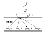
- FIG. 1 is a diagram showing an overview of a measurement system S.
- the measurement system S is a marine geophysical exploration system for analyzing sub-seafloor geological structures.
- seismic waves are generated from a seismic source 2 such as an air gun or a sparker, and a data processing device 1 analyzes the sub-seafloor geological structure using the results of measurements of the seismic waves by a number of measuring devices 4 installed on the seabed.
- the measurement system S comprises a data processing device 1, a seismic source 2, an optical communication device 3, and a number of measurement devices 4.
- the data processing device 1, the seismic source 2, and the optical communication device 3 are mounted on a ship 100 capable of moving on the ocean.
- the multiple measurement devices 4 are installed on the seabed at intervals of at least a predetermined distance.
- the data processing device 1 is, for example, a computer, which acquires measurement data indicating the vibration state of the seabed observed by multiple measuring devices 4 at the time when seismic waves are emitted, and analyzes the acquired measurement data. That is, the data processing device 1 analyzes the measurement data of the measuring devices 4 installed on the seabed and the seismic waves detected by the measuring devices 4 in response to the emission of seismic waves from a seismic source 2 toward the seabed from a ship sailing on the sea during a measurement period. As shown in FIG. 1A, the data processing device 1 controls the multiple measuring devices 4 by sending and receiving acoustic signals, and receives the measurement data generated by the multiple measuring devices 4. The data processing device 1 also acquires information indicating absolute time from, for example, a PTP network or a GPS (Global Positioning System).
- GPS Global Positioning System
- the seismic source 2 generates seismic waves during the measurement period.
- the seismic source 2 generates seismic waves, for example, under the control of the data processing device 1, but may also generate seismic waves under the control of a control device different from the data processing device 1 (for example, a computer installed on a ship different from the ship 100).
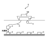
- the optical communication device 3 acquires measurement data from at least one measuring device 4 by optically communicating with it based on the control of the data processing device 1.
- the optical communication device 3 emits a first optical signal to the measuring device 4 underwater, and receives a second optical signal transmitted by the measuring device 4 that has received the first optical signal.
- the optical communication device 3 is connected to the data processing device 1 by a cable C, and, based on the control of the data processing device 1, it dives to a position where it can perform optical communication with the measuring device 4, and then performs optical communication with the measuring device 4.
- the optical communication device 3 moves sequentially to the vicinity of multiple measuring devices 4, and acquires measurement data from the multiple measuring devices 4 sequentially.
- the measurement system S may have multiple optical communication devices 3, and the multiple optical communication devices 3 may acquire measurement data from the multiple measuring devices 4.
- the measuring device 4 generates measurement data indicating the amount of vibration of the measuring device 4.
- the measurement data indicates the amount of vibration of the measuring device 4 caused by seismic waves.
- the measurement data is data indicating the magnitude of vibration detected by a sensor possessed by the measuring device 4, and is, for example, data including a measurement value generated by sampling the signal output by the sensor every millisecond.
- the measurement data is associated with the internal time kept by an oscillator inside the measuring device 4.
- the measuring device 4 transmits the measurement data to the optical communication device 3 by an optical signal.
- the internal time of the measuring device 4 is different from the absolute time because it is measured by an oscillator built into the measuring device 4. Furthermore, due to the aging characteristics of the oscillator of the measuring device 4, the frequency of the oscillator changes over time. As a result, a difference occurs between the internal time that the measuring device 4 associates with the measurement data and the absolute time. Even if a chip-scale atomic clock (CSAC), which has relatively good aging characteristics, is used as the oscillator, a frequency offset occurs over time.
- CSAC chip-scale atomic clock
- the data processing device 1 therefore uses an acoustic signal or an optical signal to determine the time difference between the absolute time and the internal time in the measuring device 4 at the start and end of the measurement, and corrects the internal time associated with the measurement data based on the determined result. If the oscillator in the measuring device 4 has an approximately constant amount of change in frequency offset per unit time regardless of the passage of time, the time difference between the absolute time and the internal time at each measurement point within the measurement period also changes linearly. In other words, the time difference per unit time is approximately constant. The data processing device 1 uses this characteristic to calculate the difference between the internal time and the absolute time corresponding to each measurement value by multiplying the amount of change in the time difference per unit time by the time elapsed since the start of the measurement. The data processing device 1 corrects the internal time associated with the measurement data based on the calculated time difference.
- the data processing device 1 By operating the data processing device 1 in this manner, the data processing device 1 does not need to determine the time difference between the absolute time and the internal time of the measuring device 4 using an acoustic signal or optical signal continuously while the measuring device 4 is measuring, but only needs to determine the time difference between the start and end points of the measurement. Therefore, even if multiple measuring devices 4 are not connected to a PTP network, the data processing device 1 can analyze the measurement data with high accuracy without significantly reducing measurement efficiency.
- Measurements for analyzing the subseafloor geological structure are carried out periodically. For example, measurements are carried out over several days to several weeks once a year. If multiple measurement devices 4 are installed each time a measurement period is required, the installation work takes a lot of time, resulting in poor measurement efficiency. Therefore, the measurement system S in this embodiment is configured to have multiple measurement devices 4 installed in advance on the seabed measure seismic waves during multiple measurement periods spanning multiple years.
- the measuring device 4 runs on batteries, if it is installed on the seabed and operates for a long period of time, the battery will be depleted in a short time. Therefore, in the measurement system S, multiple measuring devices 4 are configured to start up at the start of a measurement period and stop measuring operation when the measurement period ends.
- the measuring device 4 that has stopped measuring operation enters a sleep state in which its oscillator is stopped to reduce power consumption, while maintaining the function of receiving acoustic signals from the data processing device 1.
- the measuring device 4 has, for example, a measurement state in which measurement is performed, a standby state in which the oscillator is operating and no measurement is being performed, and a sleep state in which the oscillator is stopped and no measurement is being performed.
- FIGS. 2 and 3 are diagrams for explaining the procedure for starting up multiple measuring devices 4.
- FIG. 2 shows a schematic diagram of multiple measuring devices 4 as viewed from above.
- the circles ( ⁇ ) shown in FIG. 2 indicate measuring devices 4 installed on the seabed.
- the numbers under the circles are identification information (ID) for identifying the measuring devices 4.
- ID identification information
- the data processing device 1 transmits an acoustic signal including control information to the measuring device 4 within the range reached by the acoustic signal (e.g., the range within the dashed frame in FIG. 2), thereby enabling the measuring device 4 to start a measurement operation.
- the data processing device 1 transmits a start command, a synchronization command, and a recording start command, thereby enabling the measuring device 4 to start a measurement operation.
- the dashed arrow in FIG. 2 represents a start command, and the solid arrow represents a synchronization command.
- the data processing device 1 may transmit parameters required for measurement (e.g., sampling interval or preamplifier gain) to the measuring device 4.
- the start-up command includes a character string corresponding to an instruction to transition the measuring device 4 from a sleep state to a state where it can measure, and the ID of the measuring device 4.
- the synchronization command includes a character string corresponding to an instruction to request the internal time of the measuring device 4, and the ID of the measuring device 4.
- the data processing device 1 may send a synchronization command including an absolute time recognized by the data processing device 1.
- synchronization the process in which the data processing device 1 determines the relationship between the absolute time and the internal time of the measuring device 4 based on the internal time received from the measuring device 4 by sending a synchronization command to the measuring device 4 is referred to as "synchronization".
- the start recording command includes a character string corresponding to an instruction to start recording measurement data, and the ID of the measuring device 4.
- a measuring device 4 with no letter in a circle shown in Figure 2 (for example, a measuring device 4 with an ID of 0606) is in a stopped state.
- a measuring device 4 with a "W” in a dashed circle indicates that it has received a startup command and is currently executing startup processing.
- a measuring device 4 with a "W” in a solid circle indicates that it has completed startup, but synchronization has not yet been completed.
- a measuring device 4 with an "S” in a dashed circle indicates that it has received a synchronization command and is currently executing synchronization processing.
- a measuring device 4 with an "S” in a solid circle indicates that synchronization has been completed.
- FIG. 3 is a diagram showing an example of a management table indicating the state of each measuring device 4.
- the ID of the measuring device 4 information indicating whether startup has been completed, information indicating whether synchronization has been completed, the previous action (i.e., the action executed immediately before), and the time at which the action was executed are associated with each other.
- the data processing device 1 sends startup commands and synchronization commands to different measuring devices 4 in a time-division manner.
- the data processing device 1 transmits a synchronization command to the already started second measuring device 4 during the period from when the start-up command is transmitted to the first measuring device 4 until the start-up of the first measuring device 4 is completed.
- the multiple measuring devices 4 can be brought into a state in which they can measure in a shorter time than if the start-up command was transmitted to the measuring device 4 and then the measuring device 4 waited until the measuring device 4 started up.
- the measuring devices 4 can be brought into a state in which they can measure reliably in a shorter time than if a person were to start up each measuring device 4.
- the data processing device 1 also activates multiple measuring devices 4 while proceeding in a fixed direction. As an example, as shown in FIG. 2, the data processing device 1 transmits an activation command to multiple measuring devices 4 located in front of the ship 100, and transmits a synchronization command to the multiple measuring devices 4 after the ship 100 moves to a position ahead of the activated multiple measuring devices 4.
- the data processing device 1 transmits commands to multiple measuring devices 4 located at the front of the vessel 100 on which the data processing device 1 is mounted and capable of receiving acoustic signals, and to multiple measuring devices 4 located at the rear of the vessel 100 and capable of receiving acoustic signals.
- the data processing device 1 can bring multiple measuring devices 4 into a state where they can make measurements in a shorter time than if commands were sent only to measuring devices 4 located either at the front or rear of the vessel 100.
- the data processing device 1 may send a recording start command to the measurement device 4 that has completed synchronization after receiving a response to the synchronization command from the measurement device 4 and completing synchronization.
- the recording start command may be a command that includes an instruction to start recording immediately, or may be a command that indicates the time to start recording.
- the data processing device 1 may send recording start commands continuously to multiple measurement devices 4 after synchronization of all measurement devices 4 is completed and before the seismic source generates seismic waves.
- the data processing device 1 sequentially starts up and synchronizes the multiple measuring devices 4 before a measurement period, and when the measurement period ends, the measuring devices 4 go into sleep mode to reduce battery consumption. Because the measurement system S is configured in this way, it is possible to have multiple measuring devices 4 measure seismic waves efficiently over a long period of time.
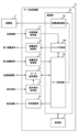
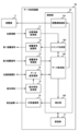
- [Configuration of data processing device 1] 4 is a diagram showing the configuration of the data processing device 1.
- the data processing device 1 has a position information acquisition unit 11, an acoustic signal transmission unit 12, an acoustic signal reception unit 13, a data transmission/reception unit 14, an absolute time acquisition unit 15, an external communication unit 16, a storage unit 17, and a control unit 18.
- the control unit 18 has a seismic source control unit 181, a command creation unit 182, a data acquisition unit 183, a time difference identification unit 184, and a correction unit 185. Note that some of the functional units of the control unit 18 may be provided in a device other than the data processing device 1.
- the location information acquisition unit 11 acquires location information indicating the location of the data processing device 1, i.e., the location of the ship 100 on which the data processing device 1 is mounted.
- the location information acquisition unit 11 acquires, for example, radio waves received from a GPS satellite as location information, and identifies the latitude and longitude based on the acquired location information.
- the location information acquisition unit 11 notifies the command creation unit 182 of the identified latitude and longitude.
- the acoustic signal transmitting unit 12 is an acoustic communication unit that transmits a first acoustic signal to the measuring device 4.
- the acoustic signal transmitting unit 12 transmits a first acoustic signal including control data (e.g., various commands) input from the command creating unit 182 based on the control of the command creating unit 182.
- the acoustic signal receiving unit 13 transmits a first acoustic signal including a command to a measuring device 4 within a predetermined range from the position of the ship 100 indicated by the position information acquired by the position information acquiring unit 11 by referring to the respective positions of the multiple measuring devices 4 stored in the memory unit 17.
- the predetermined range is a range within which the measuring device 4 can receive the first acoustic signal transmitted by the acoustic signal transmitting unit 12.
- the acoustic signal transmitting unit 12 transmits a first acoustic signal including a startup command, which is startup data for starting up the measuring device 4, to each of the multiple measuring devices 4.
- the acoustic signal transmitting unit 12 transmits a first acoustic signal including a synchronization command indicating absolute time (i.e., a synchronization command including time data) to a measuring device 4 from which the acoustic signal receiving unit 13 has received a second acoustic signal including response data to the startup command.
- the acoustic signal transmitting unit 12 also transmits a first acoustic signal including a recording start command, which is recording start data indicating an instruction to start recording measurement data, to a measuring device 4 from which the acoustic signal receiving unit 13 has received a response to the first acoustic signal including a synchronization command.
- the acoustic signal transmitting unit 12 transmits a first acoustic signal including recording start data to a measuring device 4 that has transmitted response data to the synchronization command.
- the acoustic signal transmitting unit 12 may transmit a recording start command including the ID of one measuring device 4, or may transmit a recording start command including the IDs of multiple measuring devices 4 that have completed synchronization.
- the acoustic signal transmitting unit 12 may transmit a recording start command including information indicating that the command is intended for all measuring devices 4.
- the acoustic signal receiving unit 13 is an acoustic communication unit that receives a second acoustic signal emitted by the measuring device 4 that has received the first acoustic signal.
- the acoustic signal receiving unit 13 receives, for example, the second acoustic signal indicating the internal time of the measuring device 4.
- the acoustic signal receiving unit 13 identifies the internal time based on the time data included in the received acoustic signal, and notifies the data acquisition unit 183 of the identified internal time.
- the data transmission/reception unit 14 is a communication interface for transmitting and receiving data with the optical communication device 3.
- the data transmission/reception unit 14 transmits data input from the data acquisition unit 183 to the optical communication device 3, including an instruction to acquire the internal time from the measurement device 4, and receives time data indicating the internal time acquired by the optical communication device 3 from the measurement device 4.
- the data transmitter/receiver 14 may notify the optical communication device 3 of the absolute time acquired by the absolute time acquisition unit 15, and receive time data in which the internal time is associated with the absolute time at the time when the optical communication device 3 acquired the internal time from the measurement device 4.
- the data transmitter/receiver 14 receives data indicating the internal time acquired by the optical communication device 3 from the measurement device 4 at a time within a specified range from the time when the last measurement is performed in the measurement period.
- the data transmitter/receiver 14 notifies the data acquisition unit 183 of the acquired time data.
- the absolute time acquisition unit 15 acquires absolute time, for example, from a GPS satellite.
- the absolute time acquisition unit 15 notifies the acquired absolute time to the time difference determination unit 184.
- the absolute time acquisition unit 15 may also notify the data transmission/reception unit 14 of the absolute time.
- the external communication unit 16 transmits the measurement results, including the measurement data after the internal time has been corrected, input from the correction unit 185.
- the external communication unit 16 may transmit the measurement results to an external computer that executes a process of analyzing the measurement results and identifying the sub-seafloor geological structure, or may transmit the measurement results to another processing unit included in the control unit 18.
- the memory unit 17 has storage media such as a ROM (Read Only Memory), a RAM (Random Access Memory), and an SSD (Solid State Drive).
- the memory unit 17 stores programs executed by the control unit 18.
- the memory unit 17 also stores various data for causing the multiple measuring devices 4 to perform measurements.
- the memory unit 17 stores, for example, the position of each of the multiple measuring devices 4 in association with the identification information of the measuring device 4. Specifically, the memory unit 17 stores the latitude and longitude of the measuring devices 4 in association with the IDs of the multiple measuring devices 4.
- the storage unit 17 also stores a management table such as that shown in FIG. 3. Furthermore, the storage unit 17 stores multiple pieces of measurement data acquired from the measurement devices 4 in association with the IDs of the multiple measurement devices 4. The storage unit 17 stores multiple pieces of measurement data in association with the internal time of the measurement device 4 at the time the measurement data was generated. After that, when the time corrected from the internal time by the correction unit 185 is associated with the measurement data, the storage unit 17 stores the measurement data in association with the corrected time.
- the control unit 18 has, for example, a CPU (Central Processing Unit).
- the control unit 18 executes the programs stored in the storage unit 17, thereby functioning as an epicenter control unit 181, a command creation unit 182, a data acquisition unit 183, a time difference determination unit 184, and a correction unit 185.
- a CPU Central Processing Unit
- the epicenter control unit 181 transmits an instruction to generate seismic waves to the epicenter 2.
- the epicenter control unit 181 causes the epicenter 2 to generate seismic waves, for example, after the acoustic signal transmission unit 12 transmits a first acoustic signal including a recording start command to the multiple measuring devices 4.
- the epicenter control unit 181 transmits an instruction to generate seismic waves to the epicenter 2, for example, after receiving a notification from the data acquisition unit 183 that all measuring devices 4 are ready to perform measurements.
- the epicenter control unit 181 may cause the epicenter 2 to generate seismic waves at a predetermined date and time, or may cause the epicenter 2 to generate seismic waves in response to receiving an instruction from an external device.
- the data processing device 1 may not have the epicenter control unit 181, and an external control device may function as the epicenter control unit 181.
- the command creation unit 182 creates commands to be sent by the acoustic signal transmission unit 12 to the measuring device 4.
- the command creation unit 182 creates, for example, a startup command, a synchronization command, and a recording start command, and inputs the created commands to the acoustic signal transmission unit 12.
- the command creation unit 182 selects a measuring device 4 within a predetermined range from the latitude and longitude input from the position information acquisition unit 11 by referring to the latitude and longitude of the locations where multiple measuring devices 4 are installed that are stored in the memory unit 17.
- the command creation unit 182 creates a command that includes the ID of the selected measuring device 4.
- the command creation unit 182 creates a startup command for a measuring device 4 in a sleep state among multiple measuring devices 4 within a predetermined range.
- the command creation unit 182 creates a synchronization command for that measuring device 4.
- the command creation unit 182 creates a recording start command for that measuring device 4.
- the command creation unit 182 When the command creation unit 182 inputs the created command to the acoustic signal transmission unit 12, it updates the "last action" in the management table stored in the memory unit 17. When the command creation unit 182 inputs a start-up command to the acoustic signal transmission unit 12, it sets the “last action” corresponding to the ID of the measuring device 4 included in the start-up command to "starting up.” When the command creation unit 182 inputs a synchronization command to the acoustic signal transmission unit 12, it sets the "last action” corresponding to the ID of the measuring device 4 included in the synchronization command to "synchronizing.”
- the data acquisition unit 183 acquires various data transmitted from the measuring device 4.
- the data acquisition unit 183 acquires response data to a command transmitted by the acoustic signal transmission unit 12 via the acoustic signal reception unit 13.
- the data acquisition unit 183 notifies the command creation unit 182 that the response data has been acquired.
- the data acquisition unit 183 When the data acquisition unit 183 acquires response data, it updates the contents of the "most recent action" in the management table stored in the storage unit 17. When the data acquisition unit 183 acquires response data indicating startup, for example, it updates the "most recent action" corresponding to the ID of the measuring device 4 included in the response data to "startup completed.” When the data acquisition unit 183 acquires response data including the internal time of the measuring device 4 sent by the measuring device 4 in response to receiving a synchronization command, it updates the "most recent action” corresponding to the ID of the measuring device 4 included in the response data to "synchronization completed.” The data acquisition unit 183 associates the absolute time when the synchronization command was sent and the internal time indicated by the response data with the ID of the measuring device 4 and stores them in the storage unit 17.
- the data acquisition unit 183 acquires response data indicating that the measuring device 4 has started recording, it updates the "last action" corresponding to the ID of the measuring device 4 contained in the response data to "start recording”.
- the data acquisition unit 183 receives response commands to the start recording command from all measuring devices 4, that is, when the "last action" of all measuring devices 4 has become “start recording”, it notifies the epicenter control unit 181 that measurement can start.
- the data acquisition unit 183 may further acquire the emission time, which is the absolute time when the optical communication device 3 emits the first optical signal, and the internal time included in the second optical signal received by the optical communication device 3.
- the second optical signal is an optical signal transmitted by the measurement device 4 in response to receiving the first optical signal.
- the data acquisition unit 183 associates the emission time and the internal time with the ID of the measurement device 4, stores them in the memory unit 17, and notifies the time difference determination unit 184.
- the data acquisition unit 183 acquires measurement data from the measuring device 4 via the data transmission/reception unit 14.
- the data acquisition unit 183 acquires multiple pieces of measurement data each indicating a measurement value corresponding to a different time. For example, after the measurement period ends, the data acquisition unit 183 acquires multiple pieces of measurement data collected from the measuring device 4 by the optical communication device 3 through optical communication from the data transmission/reception unit 14.
- the data acquisition unit 183 associates the acquired measurement data with the ID of the measuring device 4 and stores it in the memory unit 17, thereby enabling the time difference identification unit 184 to refer to the measurement data.
- the time difference determination unit 184 refers to the measurement data stored in the memory unit 17 to determine the time difference between the absolute time and the internal time of the measurement device 4 associated with the measurement data. Specifically, the time difference determination unit 184 refers to the absolute time and internal time stored in the memory unit 17 in association with the ID of the measurement device 4 to determine a first time difference, which is the difference between the start absolute time when the measurement period starts and the internal time of the measurement device 4 associated with the measurement data at the time when the measurement period starts. In addition, the time difference determination unit 184 determines a second time difference, which is the difference between the end absolute time when the measurement period ends and the internal time associated with the measurement data at the time when the measurement period ends.
- the time difference determination unit 184 determines at least one of the first time difference and the second time difference based on the difference between the absolute time when the acoustic signal transmission unit 12 transmitted the first acoustic signal and the internal time indicated by the second acoustic signal received by the acoustic signal reception unit 13.
- the time difference determination unit 184 determines the first time difference based on the difference between the absolute time transmitted by the command creation unit 182 in the synchronization command and the internal time of the measurement device 4 included in the response data to the synchronization command, for example.
- the time difference determination unit 184 also determines the second time difference based on the difference between the absolute time included in the measurement data acquisition request command transmitted by the optical communication device 3 to the measurement device 4 after the measurement period ends and the internal time of the measurement device 4 included in the response data to the measurement data acquisition request command.
- the absolute time at the time when the measuring device 4 receives the first acoustic signal differs from the absolute time at which the acoustic signal transmitting unit 12 transmits the first acoustic signal.
- the time difference determining unit 184 may determine at least one of the first time difference and the second time difference based on the difference between the time obtained by adding the time required for the first acoustic signal to reach the measuring device 4 to the absolute time at which the acoustic signal transmitting unit 12 transmits the first acoustic signal and the internal time indicated by the second acoustic signal received by the acoustic signal receiving unit 13.
- the time difference determination unit 184 may determine at least either the first time difference or the second time difference based on the difference between the internal time indicated by the second acoustic signal and the time obtained by adding the time required for the measurement device 4 to determine the internal time after receiving the first acoustic signal to the absolute time when the acoustic signal transmission unit 12 transmitted the first acoustic signal. In this way, the time difference determination unit 184 uses the propagation time of the first acoustic signal and the processing time in the measurement device 4, thereby improving the accuracy of determining the difference between the absolute time and the internal time.
- the time difference determination unit 184 may determine both the first time difference and the second time difference based on the difference between the absolute time when the acoustic signal transmitting unit 12 transmits the first acoustic signal and the internal time included in the second acoustic signal received by the acoustic signal receiving unit 13, but may also determine at least one of them based on the difference between the light emission time, which is the absolute time when the optical communication device 3 transmits the first optical signal, and the internal time included in the second optical signal received by the optical communication device 3 from the measurement device 4.
- the time difference determination unit 184 may determine at least one of the first time difference and the second time difference based on the difference between the absolute time when the optical communication device 3 transmits the first optical signal plus the time it takes for the first optical signal to reach the measurement device 4 and the internal time indicated by the second optical signal received by the optical communication device 3.
- the absolute time when the optical communication device 3 transmits the first optical signal may be the time when the data transmission/reception unit 14 instructs the optical communication device 3 to transmit the first optical signal.
- the optical communication device 3 emits the first optical signal at a position closer to the measurement device 4 than the data processing device 1. Therefore, the propagation time required for the first optical signal emitted by the optical communication device 3 to reach the measurement device 4 is shorter than the propagation time required for the first acoustic signal transmitted by the acoustic signal transmitter 12 to reach the measurement device 4, and therefore there is less variation in the propagation time. As a result, the accuracy of determining the time difference is improved by using an optical signal to determine the time difference.
- the time difference determination unit 184 determines the first time difference using an acoustic signal at the start of the measurement, and determines the second time difference using an optical signal at the end of the measurement when the optical communication device 3 moves close to the measurement device 4 to collect the measurement data. By operating in this manner, the time difference determination unit 184 can determine the time difference with high accuracy based on the optical signal without increasing the time that the optical communication device 3 spends moving to obtain the internal time, thereby achieving both measurement efficiency and measurement accuracy.
- the correction unit 185 reads out the multiple pieces of measurement data stored in the memory unit 17, and corrects the internal times associated with the multiple pieces of measurement data based on at least the first time difference and the second time difference.
- the correction unit 185 stores the multiple pieces of measurement data with the corrected internal times in the memory unit 17.
- the correction unit 185 determines the amount of change per unit time in the difference between the absolute time and the internal time based on the time difference between the absolute start time, which is the absolute time when the measurement starts, and the absolute end time, which is the absolute time when the measurement ends, and the difference between the first time difference and the second time difference.
- the correction unit 185 corrects the internal times associated with the multiple measurement data based on the determined amount of change.
- the correction unit 185 determines the difference between the internal time and the absolute time at the internal time corresponding to the measurement data to be corrected by adding to the first time difference the value obtained by multiplying the elapsed time from the start absolute time to the internal time by the amount of change per unit time.
- the correction unit 185 corrects the internal time of the measurement data to be corrected based on the determined difference. In this way, if the amount of change per unit time in the frequency offset of the oscillator possessed by the measurement device 4 is approximately constant regardless of the passage of time, the time difference determination unit 184 can efficiently correct the internal time corresponding to the measurement data using the first time difference at the start of measurement and the second time difference at the end of measurement.
- the data acquisition unit 183 may also send a synchronization command during the measurement period to acquire the internal time of the measurement device 4, and the correction unit 185 may correct the internal time of the measurement data based on the difference between the absolute time during the measurement period and the internal time of the measurement device 4.
- the correction unit 185 may also correct the internal time of the measurement data based on the time difference between the internal time and the absolute time identified based on the synchronization command issued at a number of points corresponding to the linearity of the aging characteristics of the oscillator possessed by the measurement device 4. By operating in this manner, the correction unit 185 can appropriately correct the internal time corresponding to the measurement data in accordance with the aging characteristics of the oscillator possessed by the measurement device 4.
- FIG. 5 is a diagram showing the configuration of the measuring device 4.
- the measuring device 4 has an oscillator 41, a sensor 42, an acoustic signal receiving unit 43, an acoustic signal transmitting unit 44, an optical signal receiving unit 45, an optical signal transmitting unit 46, a storage unit 47, and a control unit 48.
- the control unit 48 has a data creating unit 481 and a data communication unit 482.
- the oscillator 41 generates an oscillation signal used to keep internal time in the measuring device 4.
- the oscillator 41 is, for example, a chip-scale atomic oscillator, but may be another type of oscillator.
- the sensor 42 generates a detection signal whose level changes according to the vibration of the measuring device 4.
- the sensor 42 inputs the detection signal to the data creation unit 481.
- the acoustic signal receiving unit 43 receives a first acoustic signal transmitted from the data processing device 1.
- the acoustic signal receiving unit 43 inputs data such as the command and absolute time contained in the received first acoustic signal to the data communication unit 482.
- the acoustic signal transmitting unit 44 transmits a second acoustic signal indicating the internal time at which the first acoustic signal was received to the data processing device 1.
- the optical signal receiving unit 45 receives a first optical signal transmitted from the optical communication device 3.
- the optical signal receiving unit 45 inputs data such as commands and absolute time contained in the received first optical signal to the data communication unit 482.
- the optical signal transmitting unit 46 transmits a second optical signal indicating the internal time at which the first optical signal was received.
- the optical signal transmitting unit 46 transmits the second optical signal including the internal time input from the data communication unit 482, for example, to the optical communication device 3.
- the storage unit 47 has storage media such as ROM, RAM, and SSD.
- the storage unit 47 stores the programs executed by the control unit 48.
- the storage unit 47 also stores the measurement data created by the data creation unit 481.
- the control unit 48 has, for example, a CPU.
- the control unit 48 functions as a data creation unit 481 and a data communication unit 482 by executing a program stored in the storage unit 47.
- the data creation unit 481 functions as a measurement data creation unit that creates multiple pieces of measurement data associated with the internal time measured based on the oscillator 41.
- the data creation unit 481 creates multiple pieces of measurement data indicating the sampled signal level (i.e., the measurement value) by, for example, sampling the detection signal input from the sensor 42 at a predetermined time interval (for example, 1 millisecond intervals).
- the data creation unit 481 associates the multiple pieces of measurement data with the internal time and stores them in the memory unit 47.
- the data creation unit 481 may measure the internal time by counting the oscillation signal input from the oscillator 41, or may identify the internal time based on data indicating the internal time input from the oscillator 41.
- the data communication unit 482 transmits, via the acoustic signal transmission unit 44, response data to a command contained in the first acoustic signal received from the data processing device 1 via the acoustic signal reception unit 43.
- the data communication unit 482 also transmits, via the optical signal transmission unit 46, response data to a command contained in the optical signal received from the optical communication device 3 via the optical signal reception unit 45.
- the data communication unit 482 receives a synchronization command, it acquires the internal time at the time the synchronization command was received from the oscillator 41 or the data creation unit 481, and transmits response data including the acquired internal time.
- the data communication unit 482 also transmits the multiple pieces of measurement data created by the data creation unit 481 to the optical communication device 3 via the optical signal transmission unit 46. Specifically, the data communication unit 482 transmits the multiple pieces of measurement data stored in the storage unit 47 in association with the internal time.
- Fig. 6 and Fig. 7 are diagrams for explaining the aging characteristics of an oscillator.
- Fig. 6 shows the characteristics of an oscillator whose aging characteristics are worse than those of oscillator 41
- Fig. 7 shows the aging characteristics of oscillator 41.
- Fig. 6A and Fig. 7A show the characteristics in the initial state
- Fig. 6B and Fig. 7B show the characteristics after a long period of time (several years) has passed.
- the horizontal axis in Figures 6 and 7 indicates the number of days that have passed since the start of measurement.
- the thin solid line in Figures 6 and 7 indicates the amount of clock drift (left vertical axis).
- the thick solid line indicates a state in which the amount of clock drift changes linearly over time, and the correction unit 185 corrects the internal time corresponding to multiple measurement data under the assumption that the amount of clock drift changes as indicated by the thick solid line.
- the dashed line indicates the residual error (right vertical axis) after the correction unit 185 corrects the internal time. The residual error is greatest near the center of the measurement period, and in Figure 6, a maximum residual error of approximately 0.44 milliseconds occurs.
- the residual error is approximately 0.009 milliseconds, and it can be seen that the internal time corresponding to the measurement data is corrected with high accuracy by the correction process of the correction unit 185.
- the process of correcting the internal time corresponding to the measurement data during the measurement period based on the first time difference at the start of the measurement and the second time difference at the end of the measurement is particularly effective.
- FIG. 8 is a diagram illustrating the difference between calculating the second time difference using an acoustic signal at the end of the measurement and calculating the second time difference using an optical signal.
- the solid line indicates the amount of clock drift, and the dashed line indicates the maximum and minimum values of the error due to correction.
- FIG. 8A shows a case where the time difference is determined based on the acoustic signal at the start and end of the measurement.
- FIG. 8B shows a case where the first time difference is determined based on the acoustic signal at the start of the measurement, and the second time difference is determined based on the optical signal at the end of the measurement.
- the measurement system S may be configured to calibrate the frequency of the oscillator 41 when the measurement period ends.
- FIG. 9 is a diagram showing the configuration of a measuring device 4 capable of calibrating the frequency.
- the measuring device 4 shown in FIG. 9 differs from the measuring device 4 shown in FIG. 5 in that it further includes a calibration unit 483, but is otherwise the same.
- correction unit 185 determines the frequency deviation of the oscillator of measurement device 4 at the end of the measurement period based on the first time difference and the second time difference, and notifies measurement device 4 of the determined frequency deviation.
- Correction unit 185 calculates the amount of internal time deviation per unit time, for example, by dividing the difference between the first time difference and the second time difference by the measurement period. Since the amount of internal time deviation per unit time is proportional to the magnitude of the frequency deviation, correction unit 185 can calculate the frequency deviation based on the amount of internal time deviation per unit time.
- the calibration unit 483 calibrates the frequency of the oscillator 41 based on the frequency deviation notified from the data processing device 1. Specifically, the calibration unit 483 changes the voltage of a control signal used to control the oscillation frequency of the oscillator 41 according to the frequency deviation. When the frequency deviation is, for example, +1.0 ⁇ 10-10 , the control voltage is changed so as to lower the oscillation frequency of the oscillator 41 by a frequency equivalent to the frequency deviation of 1.0 ⁇ 10-10 .
- the calibration unit 483 may calibrate the frequency of the oscillator 41 when the frequency deviation at the time when the measurement period ends is equal to or greater than a threshold value.
- the calibration unit 483 may calibrate the frequency of the oscillator 41 using the average value of the time difference between the absolute time transmitted by the optical communication device 3 via an optical signal and the internal time at the time when the measurement device 4 receives the optical signal, obtained multiple times over a certain period of time (e.g., 10 minutes).
- FIG. 10 is a diagram for explaining the calibration of the frequency of oscillator 41 by calibration unit 483.
- FIG. 10 it is assumed that there is a measurement period of 40 days per year.
- FIG. 10 it is shown that the frequency offset becomes large while oscillator 41 is operating, and that the frequency offset does not change while oscillator 41 is stopped.
- the error bars extending above and below the black dot indicating the frequency offset indicate the error range (magnitude of instability) caused by the power cycle.
- Fig. 10A shows the change in frequency deviation when the calibration unit 483 does not calibrate the frequency of the oscillator 41.
- Fig. 10B shows the change in frequency deviation when the calibration unit 483 calibrates the frequency of the oscillator 41 when the frequency deviation becomes +3.0 ⁇ 10 -10 or more.
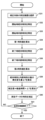
- Figures 11 to 13 are flowcharts showing the flow of processing in the data processing device 1.
- Figures 11 and 12 show the flow of processing from the start to the end of measurement in one measurement period.
- Figure 13 shows the flow of correction processing of the internal time corresponding to the measurement data.
- the flowchart shown in FIG. 11 starts from the point when all the measuring devices 4 are in a sleep state.
- the command creation unit 182 monitors whether the timing to start the measuring devices 4, i.e., whether the measurement period has arrived (S11). If the command creation unit 182 determines that the measurement period has arrived (YES in S11), it selects a measuring device 4 that is within a predetermined range from the position of the ship 100 and is in a sleep state (S12). The command creation unit 182 transmits a start-up command to the selected measuring device 4 (S13).
- the command creation unit 182 selects a measurement device 4 that is within a predetermined range from the position of the ship 100 and for which synchronization has not been completed (S14).
- the command creation unit 182 transmits a synchronization command to the selected measurement device 4 (S15).
- the time difference determination unit 184 determines the first time difference based on the relationship between the internal time and the absolute time at which the command creation unit 182 sent the synchronization command.
- the time difference determination unit 184 associates the determined first time difference with the ID of the measurement device 4 and stores it in the storage unit 17 (S16).
- the time difference determination unit 184 may not determine the first time difference at this point, and the data acquisition unit 183 may associate the absolute time at which the synchronization command was sent with the internal time received from the measurement device 4 and store them in the storage unit 17.
- the command creation unit 182 sends a recording start command to the measuring device 4 that received the response data to the synchronization command (S17).
- the command creation unit 182 refers to the management table stored in the memory unit 17 and determines whether synchronization of all measuring devices 4 is complete and preparations for recording measurement data are complete (S18). If preparations for all measuring devices 4 are not complete (NO in S18), the command creation unit 182 repeats the processes from S12 to S17. If preparations for all measuring devices 4 are complete (YES in S18), the command creation unit 182 notifies the epicenter control unit 181 that preparations for measurement are complete, and the epicenter control unit 181 generates seismic waves in the epicenter 2 (S19).
- the epicenter control unit 181 generates seismic waves in the epicenter 2 until the last scheduled measurement is completed (NO in S20). When the last scheduled measurement is completed (YES in S20), the epicenter control unit 181 notifies the command creation unit 182 that the measurement has been completed.
- the command creation unit 182 sends a recording end command to the measuring device 4 via the data transmission/reception unit 14 (S21).
- the measuring device 4 that has received the recording end command ends recording of the measurement data and transitions to a standby state.
- the data acquisition unit 183 acquires multiple pieces of measurement data via the optical communication device 3 (S22).
- the data acquisition unit 183 stores the acquired multiple pieces of measurement data in the memory unit 17, associating them with the ID of the measuring device 4.
- the data acquisition unit 183 also acquires, via the data transmission/reception unit 14, the absolute time at the time when the optical communication device 3 requests the internal time from the measurement device 4 in response to the end of the measurement, and the internal time acquired by the optical communication device 3 from the measurement device 4 (S23).
- the time difference determination unit 184 determines a second time difference based on the absolute time at the time when the measurement was completed acquired by the data acquisition unit 183 and the internal time of the measurement device 4 at that time (S24).
- the time difference determination unit 184 associates the determined second time difference with the ID of the measurement device 4 and stores it in the storage unit 17.
- the correction unit 185 analyzes the multiple pieces of measurement data.
- the correction unit 185 corrects the internal time associated with the multiple pieces of measurement data based on the first time difference and the second time difference stored in the memory unit 17 in association with the ID of the common measurement device 4 (S25).
- the correction unit 185 outputs the measurement result including the multiple pieces of measurement data after correction (S26).
- FIG. 13 is a flowchart showing the flow of the measurement data correction process (S25).
- the correction unit 185 selects a measurement device 4 for which measurement data is to be corrected (S31).
- the method by which the correction unit 185 selects the measurement device 4 is arbitrary, and the correction unit 185 selects, for example, in the order of the IDs of the measurement devices 4.
- the correction unit 185 then identifies the absolute start time stored in the storage unit 17 in association with the ID of the selected measurement device 4 (S32).
- the correction unit 185 also identifies the internal start time corresponding to the absolute start time (S33).
- the correction unit 185 calculates the first time difference based on the absolute start time and the internal start time (S34). As described above, the correction unit 185 may calculate the first time difference based further on the time required from when the position information acquisition unit 11 transmits a first acoustic signal including a synchronization command until the first acoustic signal reaches the measurement device 4.
- the correction unit 185 identifies the end absolute time and the end internal time stored in the memory unit 17 in association with the ID of the selected measurement device 4 (S35, S36). The correction unit 185 calculates the second time difference based on the end absolute time and the end internal time (S37). The correction unit 185 may calculate the second time difference based further on the time required from when the position information acquisition unit 11 transmits a first optical signal to request the internal time until the first optical signal reaches the measurement device 4.
- the correction unit 185 calculates the amount of change ⁇ T per unit time in the difference between the absolute time and the internal time based on the first time difference and the second time difference (S38). Specifically, the correction unit 185 calculates the amount of change ⁇ T by dividing the difference between the first time difference and the second time difference by the elapsed time from the start absolute time to the end absolute time.
- the correction unit 185 calculates a correction value corresponding to each internal time by multiplying the elapsed time from the measurement start internal time to the internal time when each piece of measurement data was acquired by the unit amount ⁇ T (S39).
- the correction unit 185 calculates a corrected internal time by adding the calculated correction value to the internal time when each piece of measurement data was acquired.
- the correction unit 185 corrects the time corresponding to the measurement data by updating the internal time of each piece of measurement data corresponding to the selected measurement device 4 to the corrected internal time (S40).
- the correction unit 185 may correct the internal time corresponding to all of the measurement data, or may correct the internal time corresponding to a portion of the measurement data necessary to analyze the seismic waves.
- the correction unit 185 associates the measurement data with the corrected time and stores them in the memory unit 17.
- the correction unit 185 repeats the processes from S31 to S40. If the correction of the measurement data of all the measuring devices 4 has been completed (YES in S41), the correction unit 185 ends the correction process.
- the data processing device 1 includes a time difference specifying unit 184 that specifies a first time difference, which is the difference between the internal time and the absolute start time when the measurement period starts, and a second time difference, which is the difference between the internal time and the absolute end time when the measurement period ends, and a correction unit 185 that corrects the internal time associated with a plurality of measurement data based on the first time difference and the second time difference.
- the data processing device 1 can specify the relationship between the seismic waves and the seismic waves detected by the measurement device 4 with high accuracy, with almost no effect on the time required for measurement, even if the measurement device 4 is not connected to the PTP network and cannot recognize the absolute time.
- the data processing device 1 identifies the first and second time differences, but the measurement device 4 may identify the first and second time differences and correct the internal time associated with the measurement data.
- the measurement device 4 creates measurement data associated with the corrected internal time (i.e., a time approximately equal to absolute time), and the data processing device 1 can obtain the measurement data associated with the corrected internal time.
- FIG. 14 is a diagram showing the configuration of a data processing device 1A according to this modified example.
- FIG. 15 is a diagram showing the configuration of a measurement device 4A according to this modified example.
- FIG. 16 is a flowchart showing the processing flow in the data processing device 1A according to this modified example.
- FIG. 17 is a flowchart showing the processing flow in the measurement device 4A according to this modified example.
- Data processing device 1A differs from data processing device 1 in that it does not have the time difference determination unit 184 and correction unit 185 that data processing device 1 shown in FIG. 4 has.
- the functions of each unit shown in FIG. 14 are equivalent to the functions of each unit with the same reference numerals in data processing device 1 shown in FIG. 4.
- the data acquisition unit 183 acquires the measurement data whose internal time has been corrected in the measurement device 4 via the data transmission/reception unit 14.
- the time associated with the measurement data acquired by the data acquisition unit 183 is almost equal to the absolute time, and can therefore be used as is for analysis. Therefore, the data acquisition unit 183 transmits the measurement results, including the acquired measurement data, to the outside via the external communication unit 16.
- the measurement device 4A differs from the measurement device 4 in that, in addition to the configuration of the measurement device 4 shown in FIG. 5, the measurement device 4A has a time difference determination unit 484 and a correction unit 485.
- the measurement device 4A may further have the calibration unit 483 shown in FIG. 9.
- the data communication unit 482 When the data communication unit 482 acquires a synchronization command via the acoustic signal receiving unit 43, the data communication unit 482 notifies the time difference determination unit 484 of the absolute time included in the synchronization command.
- the time difference determination unit 484 determines the time difference between the internal time at that time and the notified absolute time as the first time difference at the start of measurement.
- the time difference determination unit 484 stores the determined first time difference in the memory unit 47.
- the data communication unit 482 when the data communication unit 482 acquires the absolute time at the time when the measurement ends via the acoustic signal receiving unit 43 or the optical signal receiving unit 45, the data communication unit 482 notifies the time difference determination unit 484 of the acquired absolute time.
- the time difference determination unit 484 determines the time difference between the internal time at that time and the notified absolute time as the second time difference at the time when the measurement ends.
- the time difference determination unit 484 stores the determined second time difference in the memory unit 47.
- the time difference determination unit 484 can execute the same processing as the time difference determination unit 184. For example, the time difference determination unit 484 calculates a first time difference based on the difference between the absolute time and the internal time and the propagation time for the first acoustic signal transmitted from the data processing device 1A to reach the measurement device 4A. The time difference determination unit 484 also calculates a second time difference based on the difference between the absolute time and the internal time and the propagation time for the first optical signal transmitted from the optical communication device 3 to reach the measurement device 4A.
- the correction unit 485 corrects the internal time at which the sensor 42 outputs the measurement data, based on the first time difference and second time difference identified by the time difference identification unit 484. Similar to the correction unit 185, the correction unit 485 identifies the amount of change per unit time in the difference between the absolute time and the internal time, based on the time difference between the start absolute time, which is the absolute time at which the measurement starts, and the end absolute time, which is the absolute time at which the measurement ends, and the difference between the first time difference and the second time difference. Next, the correction unit 485 corrects the internal time associated with the multiple measurement data created by the data creation unit 481, based on the identified amount of change. The correction unit 485 notifies the data communication unit 482 of the corrected internal time, in association with the measurement data.
- the data communication unit 482 transmits the multiple pieces of measurement data associated with the corrected internal time notified by the correction unit 485 to the optical communication device 3 via the optical signal transmission unit 46.
- the flowchart of data processing device 1A shown in FIG. 16 shows the process flow from the start of measurement in one measurement period to when data processing device 1A acquires measurement data.
- the processes from S11 to S20 in the flowchart shown in FIG. 16 differ from the flowchart shown in FIG. 11 in that there is no process (S16) for identifying the first time difference, but are otherwise the same.
- the flowchart of the measuring device 4A shown in FIG. 17 starts from the point when the data processing device 1 transmits a first acoustic signal including a synchronization command.
- the time difference determining unit 484 determines the absolute time included in the synchronization command as the start absolute time (S42).
- the time difference determining unit 484 also determines the internal time at this point in time as the start internal time (S43).
- the time difference determining unit 484 calculates the difference between the start absolute time and the start internal time as the first time difference (S44).
- the measurement device 4A measures seismic waves (S45), and the data creation unit 481 creates measurement data associated with the internal time output by the oscillator 41.
- the optical signal receiving unit 45 receives a first optical signal including absolute time from the optical communication device 3 (S46).
- the time difference determination unit 484 determines the absolute time included in the first optical signal as the end absolute time (S47).
- the time difference determination unit 484 also determines the internal time at this point as the end internal time (S48).
- the time difference determination unit 484 calculates the difference between the end absolute time and the end internal time as the second time difference (S49).
- the correction unit 485 calculates the amount of change ⁇ T per unit time in the difference between the absolute time and the internal time based on the first time difference and the second time difference (S50). Specifically, the correction unit 485 calculates the amount of change ⁇ T by dividing the difference between the first time difference and the second time difference by the elapsed time from the start absolute time to the end absolute time.
- the correction unit 485 then calculates a correction value corresponding to each internal time by multiplying the elapsed time from the measurement start internal time to the internal time when each piece of measurement data was acquired by a unit amount ⁇ T (S51).
- the correction unit 485 calculates a corrected internal time by adding the calculated correction value to the internal time when each piece of measurement data was acquired.
- the correction unit 185 corrects the time corresponding to the measurement data by updating the internal time of each piece of measurement data to the corrected internal time (S52).
- the correction unit 485 may correct the internal time corresponding to all of the measurement data, or may correct the internal time corresponding to a portion of the measurement data required to analyze seismic waves.
- the correction unit 485 inputs the measurement data associated with the corrected time to the data communication unit 482.
- the data communication unit 482 transmits the measurement data with the corrected time to the optical communication device 3 via the optical signal transmission unit 46 (S53).
- Fig. 18 is a diagram showing the configuration of a data processing device 1B according to the second modification.
- Fig. 19 is a diagram showing the configuration of a measurement device 4B according to the second modification.
- the second modification is different from the data processing device 1A according to the first modification in that the data processing device 1B has a correction unit 185.
- the measurement device 4A has a time difference specifying unit 484 and a correction unit 485, but in the second modification, the measurement device 4B has a time difference specifying unit 484 and does not have a correction unit 485.
- the time difference determination unit 484 of the measurement device 4B operates together with the time difference determination unit 484 of the measurement device 4A. That is, the time difference determination unit 484 calculates a first time difference based on the difference between the absolute time and the internal time and the propagation time for the first acoustic signal transmitted from the data processing device 1A to reach the measurement device 4A. The time difference determination unit 484 also calculates a second time difference based on the difference between the absolute time and the internal time and the propagation time for the first optical signal transmitted from the optical communication device 3 to reach the measurement device 4A. The time difference determination unit 484 inputs the determined first time difference and second time difference to the data communication unit 482.
- the data creation unit 481 of the measurement device 4B also associates the multiple pieces of measurement data output by the sensor 42 with the internal time and inputs them to the data communication unit 482.
- the data communication unit 482 associates the multiple pieces of measurement data with the internal time and transmits them to the data processing device 1B via the optical signal transmission unit 46, and also transmits the first time difference and second time difference identified by the time difference identification unit 484 to the data processing device 1B.
- correction unit 185 corrects the internal times associated with each of the multiple measurement data, similar to data processing device 1. In this way, it is optional whether the time difference determination unit and correction unit are provided in the data processing device or the measurement device.
- Data processing device 2 Source 3 Optical communication device 4 Measurement device 11 Position information acquisition unit 12 Acoustic signal transmission unit 13 Acoustic signal reception unit 14 Data transmission/reception unit 15 Absolute time acquisition unit 16 External communication unit 17 Memory unit 18 Control unit 41 Oscillator 42 Sensor 43 Acoustic signal reception unit 44 Acoustic signal transmission unit 45 Optical signal reception unit 46 Optical signal transmission unit 47 Memory unit 48 Control unit 100 Ship 181 Source control unit 182 Command creation unit 183 Data acquisition unit 184 Time difference determination unit 185 Correction unit 481 Data creation unit 482 Data communication unit 483 Calibration unit 484 Time difference determination unit 485 Correction unit
Landscapes
- Physics & Mathematics (AREA)
- Life Sciences & Earth Sciences (AREA)
- Engineering & Computer Science (AREA)
- Remote Sensing (AREA)
- General Physics & Mathematics (AREA)
- Environmental & Geological Engineering (AREA)
- Geology (AREA)
- General Life Sciences & Earth Sciences (AREA)
- Acoustics & Sound (AREA)
- Geophysics (AREA)
- Electromagnetism (AREA)
- Computer Networks & Wireless Communication (AREA)
- Signal Processing (AREA)
- Oceanography (AREA)
- Geophysics And Detection Of Objects (AREA)
- Optical Communication System (AREA)
Abstract
La présente invention porte sur un dispositif de traitement de données 1 qui comprend : une unité d'acquisition de données 183 qui acquiert une pluralité d'éléments de données de mesure associés à un temps interne cadencé par un dispositif de mesure 4 qui est installé sur le fond marin, les données de mesure étant générées par le dispositif de mesure 4 sur la base d'ondes sismiques détectées par le dispositif de mesure 4 en réponse à l'émission, vers le fond marin à partir d'un navire se déplaçant sur la mer, d'ondes de vibration provenant d'une source de vibration pendant une période de mesure ; une unité d'identification de différence de temps 184 qui identifie (1) une première différence de temps, qui est la différence entre un temps de début absolu au moment où la période de mesure commence, et le temps interne associé aux données de mesure au moment où la période de mesure commence, et (2) une seconde différence de temps, qui est la différence entre un temps de fin absolu au moment où la période de mesure se termine, et le temps interne associé aux données de mesure au moment où la période de mesure se termine ; et une unité de correction 185 qui corrige le temps interne associé à la pluralité d'éléments de données de mesure sur la base d'au moins la première différence de temps et la seconde différence de temps.
Priority Applications (1)
| Application Number | Priority Date | Filing Date | Title |
|---|---|---|---|
| US19/409,606 US20260086254A1 (en) | 2023-06-15 | 2025-12-04 | Measurement system, data processing apparatus, and measuring apparatus |
Applications Claiming Priority (2)
| Application Number | Priority Date | Filing Date | Title |
|---|---|---|---|
| JP2023-098681 | 2023-06-15 | ||
| JP2023098681A JP7593679B1 (ja) | 2023-06-15 | 2023-06-15 | 測定システム、データ処理装置、測定装置、データ処理方法及びプログラム |
Related Child Applications (1)
| Application Number | Title | Priority Date | Filing Date |
|---|---|---|---|
| US19/409,606 Continuation US20260086254A1 (en) | 2023-06-15 | 2025-12-04 | Measurement system, data processing apparatus, and measuring apparatus |
Publications (1)
| Publication Number | Publication Date |
|---|---|
| WO2024257428A1 true WO2024257428A1 (fr) | 2024-12-19 |
Family
ID=93655308
Family Applications (1)
| Application Number | Title | Priority Date | Filing Date |
|---|---|---|---|
| PCT/JP2024/011321 Ceased WO2024257428A1 (fr) | 2023-06-15 | 2024-03-22 | Système de mesure, dispositif de traitement de données, dispositif de mesure, procédé de traitement de données et programme |
Country Status (3)
| Country | Link |
|---|---|
| US (1) | US20260086254A1 (fr) |
| JP (1) | JP7593679B1 (fr) |
| WO (1) | WO2024257428A1 (fr) |
Families Citing this family (1)
| Publication number | Priority date | Publication date | Assignee | Title |
|---|---|---|---|---|
| JP7665248B1 (ja) * | 2024-10-21 | 2025-04-21 | サイスガジェット株式会社 | 地震波測定方法、エージングレート測定方法、プログラム及びデータ処理装置 |
Citations (7)
| Publication number | Priority date | Publication date | Assignee | Title |
|---|---|---|---|---|
| JPH11118961A (ja) * | 1997-10-16 | 1999-04-30 | Nec Eng Ltd | 刻時補正システム |
| JP2007292662A (ja) * | 2006-04-26 | 2007-11-08 | Mitsutoyo Corp | データ記録装置及びデータ記録装置の時刻校正方法 |
| US20190094402A1 (en) * | 2017-09-25 | 2019-03-28 | Seabed Geosolutions B.V. | Temperature compensated parabolic skew estimation for clocks on an autonomous seismic node |
| US20200264330A1 (en) * | 2015-12-18 | 2020-08-20 | Bp Corporation North America, Inc. | System and Method for Correction of Receiver Clock Drift |
| CN111624656A (zh) * | 2019-02-27 | 2020-09-04 | 中国石油天然气集团有限公司 | 基于近偏移距地震信号的节点时钟漂移校正方法及装置 |
| US20210041586A1 (en) * | 2018-03-02 | 2021-02-11 | Inapril As | Method for correction of clock drift in seismic nodes, a seismic node and a seismic node handling system |
| US20210263477A1 (en) * | 2018-06-29 | 2021-08-26 | Sercel | Method and system for estimating the drift of a clock for dating seismic data samples |
-
2023
- 2023-06-15 JP JP2023098681A patent/JP7593679B1/ja active Active
-
2024
- 2024-03-22 WO PCT/JP2024/011321 patent/WO2024257428A1/fr not_active Ceased
-
2025
- 2025-12-04 US US19/409,606 patent/US20260086254A1/en active Pending
Patent Citations (7)
| Publication number | Priority date | Publication date | Assignee | Title |
|---|---|---|---|---|
| JPH11118961A (ja) * | 1997-10-16 | 1999-04-30 | Nec Eng Ltd | 刻時補正システム |
| JP2007292662A (ja) * | 2006-04-26 | 2007-11-08 | Mitsutoyo Corp | データ記録装置及びデータ記録装置の時刻校正方法 |
| US20200264330A1 (en) * | 2015-12-18 | 2020-08-20 | Bp Corporation North America, Inc. | System and Method for Correction of Receiver Clock Drift |
| US20190094402A1 (en) * | 2017-09-25 | 2019-03-28 | Seabed Geosolutions B.V. | Temperature compensated parabolic skew estimation for clocks on an autonomous seismic node |
| US20210041586A1 (en) * | 2018-03-02 | 2021-02-11 | Inapril As | Method for correction of clock drift in seismic nodes, a seismic node and a seismic node handling system |
| US20210263477A1 (en) * | 2018-06-29 | 2021-08-26 | Sercel | Method and system for estimating the drift of a clock for dating seismic data samples |
| CN111624656A (zh) * | 2019-02-27 | 2020-09-04 | 中国石油天然气集团有限公司 | 基于近偏移距地震信号的节点时钟漂移校正方法及装置 |
Also Published As
| Publication number | Publication date |
|---|---|
| JP7593679B1 (ja) | 2024-12-03 |
| US20260086254A1 (en) | 2026-03-26 |
| JP2024179667A (ja) | 2024-12-26 |
Similar Documents
| Publication | Publication Date | Title |
|---|---|---|
| US7457601B2 (en) | Precisely timed execution of a measurement or control action and synchronization of several such actions | |
| CN111149018B (zh) | 用于校准系统参数的方法和系统 | |
| US9417359B2 (en) | Ocean bottom seismic node system | |
| US20110090759A1 (en) | Seismic Acquisition System | |
| US8760963B2 (en) | Synchronous recording system and synchronous recording method | |
| US20260086254A1 (en) | Measurement system, data processing apparatus, and measuring apparatus | |
| EP1486795A1 (fr) | Terminal portable et procede pour retenir le temps GPS | |
| Kebkal et al. | Underwater acoustic modems with integrated atomic clocks for one-way travel-time underwater vehicle positioning | |
| EP2120343B1 (fr) | Contrôle Dither de fréquence d'oscillateur pour réduire une erreur temporelle cumulative dans une horloge | |
| JP2006311023A (ja) | 測位システム、情報提供装置、端末装置、情報提供装置の制御方法、情報提供装置の制御プログラム、情報提供装置の制御プログラムを記録したコンピュータ読み取り可能な記録媒体 | |
| CN108762049B (zh) | 一种基于声场互易定理的水下授时方法及系统 | |
| JP2001249174A (ja) | Gps受信機 | |
| JP7751919B1 (ja) | 測定装置 | |
| JP3037228B2 (ja) | 刻時補正システム | |
| CN114815571B (zh) | 一种星地时差的测量方法、系统、存储介质和电子设备 | |
| US20230161373A1 (en) | Clock drift | |
| CN115267789B (zh) | 双探头多波束控制方法、装置及多波束探测系统 | |
| JP7781469B1 (ja) | 地震波測定方法、プログラム及び地震波測定システム | |
| CN115856838B (zh) | 一种抑制同频异频光源干扰信号的方法和光电传感器 | |
| JP2026075025A (ja) | 測定装置 | |
| JP2013246024A (ja) | Gpsモジュール及びgpsによる位置測定方法並びにコンピュータプログラム | |
| JP2026074648A (ja) | 地震波測定方法、エージングレート測定方法、プログラム及びデータ処理装置 | |
| JP2026074649A (ja) | 地震波測定方法、プログラム及び地震波測定システム | |
| JP2019169006A (ja) | 多点同時計測システム | |
| CN101477209B (zh) | 地震采集系统 |
Legal Events
| Date | Code | Title | Description |
|---|---|---|---|
| 121 | Ep: the epo has been informed by wipo that ep was designated in this application |
Ref document number: 24823051 Country of ref document: EP Kind code of ref document: A1 |
|
| NENP | Non-entry into the national phase |
Ref country code: DE |