WO2024257428A1 - 測定システム、データ処理装置、測定装置、データ処理方法及びプログラム - Google Patents
測定システム、データ処理装置、測定装置、データ処理方法及びプログラム Download PDFInfo
- Publication number
- WO2024257428A1 WO2024257428A1 PCT/JP2024/011321 JP2024011321W WO2024257428A1 WO 2024257428 A1 WO2024257428 A1 WO 2024257428A1 JP 2024011321 W JP2024011321 W JP 2024011321W WO 2024257428 A1 WO2024257428 A1 WO 2024257428A1
- Authority
- WO
- WIPO (PCT)
- Prior art keywords
- time
- measurement
- difference
- data
- unit
- Prior art date
- Legal status (The legal status is an assumption and is not a legal conclusion. Google has not performed a legal analysis and makes no representation as to the accuracy of the status listed.)
- Ceased
Links
Images


Classifications
-
- H—ELECTRICITY
- H04—ELECTRIC COMMUNICATION TECHNIQUE
- H04B—TRANSMISSION
- H04B10/00—Transmission systems employing electromagnetic waves other than radio-waves, e.g. infrared, visible or ultraviolet light, or employing corpuscular radiation, e.g. quantum communication
- H04B10/80—Optical aspects relating to the use of optical transmission for specific applications, not provided for in groups H04B10/03 - H04B10/70, e.g. optical power feeding or optical transmission through water
-
- G—PHYSICS
- G01—MEASURING; TESTING
- G01V—GEOPHYSICS; GRAVITATIONAL MEASUREMENTS; DETECTING MASSES OR OBJECTS; TAGS
- G01V1/00—Seismology; Seismic or acoustic prospecting or detecting
- G01V1/16—Receiving elements for seismic signals; Arrangements or adaptations of receiving elements
-
- G—PHYSICS
- G01—MEASURING; TESTING
- G01V—GEOPHYSICS; GRAVITATIONAL MEASUREMENTS; DETECTING MASSES OR OBJECTS; TAGS
- G01V1/00—Seismology; Seismic or acoustic prospecting or detecting
- G01V1/16—Receiving elements for seismic signals; Arrangements or adaptations of receiving elements
- G01V1/162—Details
-
- G—PHYSICS
- G01—MEASURING; TESTING
- G01V—GEOPHYSICS; GRAVITATIONAL MEASUREMENTS; DETECTING MASSES OR OBJECTS; TAGS
- G01V1/00—Seismology; Seismic or acoustic prospecting or detecting
- G01V1/24—Recording seismic data
- G01V1/26—Reference-signal-transmitting devices, e.g. indicating moment of firing of shot
-
- G—PHYSICS
- G01—MEASURING; TESTING
- G01V—GEOPHYSICS; GRAVITATIONAL MEASUREMENTS; DETECTING MASSES OR OBJECTS; TAGS
- G01V1/00—Seismology; Seismic or acoustic prospecting or detecting
- G01V1/28—Processing seismic data, e.g. for interpretation or for event detection
-
- G—PHYSICS
- G01—MEASURING; TESTING
- G01V—GEOPHYSICS; GRAVITATIONAL MEASUREMENTS; DETECTING MASSES OR OBJECTS; TAGS
- G01V1/00—Seismology; Seismic or acoustic prospecting or detecting
- G01V1/28—Processing seismic data, e.g. for interpretation or for event detection
- G01V1/36—Effecting static or dynamic corrections on records, e.g. correcting spread; Correlating seismic signals; Eliminating effects of unwanted energy
-
- G—PHYSICS
- G01—MEASURING; TESTING
- G01V—GEOPHYSICS; GRAVITATIONAL MEASUREMENTS; DETECTING MASSES OR OBJECTS; TAGS
- G01V1/00—Seismology; Seismic or acoustic prospecting or detecting
- G01V1/38—Seismology; Seismic or acoustic prospecting or detecting specially adapted for water-covered areas
-
- G—PHYSICS
- G01—MEASURING; TESTING
- G01V—GEOPHYSICS; GRAVITATIONAL MEASUREMENTS; DETECTING MASSES OR OBJECTS; TAGS
- G01V2200/00—Details of seismic or acoustic prospecting or detecting in general
- G01V2200/10—Miscellaneous details
- G01V2200/12—Clock synchronization-related issues
Definitions
- the present invention relates to a measurement system, a data processing device, a measurement device, a data processing method, and a program.
- Patent Document 1 discloses a technology that prevents the measurement results from being affected by clock drift in the measurement device by connecting the seismic exploration equipment to a PTP (Precision Time Protocol) network via a cable, enabling the seismic exploration equipment to recognize the exact time.
- PTP Precision Time Protocol
- the present invention was made in consideration of these points, and aims to reduce the effects of clock drift on the measurement results of measurement devices installed on the seabed.
- the measurement system of the first aspect of the present invention comprises a measurement device installed on the seabed, and a data processing device that analyzes measurement data of seismic waves detected by the measurement device in response to vibration waves emitted from a source toward the seabed from a ship sailing on the sea during a measurement period.
- the measurement device has an oscillator used for timekeeping, and a measurement data creation unit that creates a plurality of pieces of measurement data associated with an internal time kept based on the oscillator.
- Either the measurement device or the data processing device has a time difference determination unit that determines (1) a first time difference that is the difference between the absolute start time at the time when the measurement period starts and the internal time associated with the measurement data at the time when the measurement period starts, and (2) a second time difference that is the difference between the absolute end time at the time when the measurement period ends and the internal time associated with the measurement data at the time when the measurement period ends, and a correction unit that corrects the internal time associated with the plurality of measurement data based on at least the first time difference and the second time difference.
- the correction unit may determine the amount of change in the difference between the absolute time and the internal time per unit time based on the time difference between the start absolute time and the end absolute time and the difference between the first time difference and the second time difference, and correct the internal time associated with the multiple measurement data based on the determined amount of change.
- the correction unit may add to the first time difference a value obtained by multiplying the amount of change by the elapsed time from the start absolute time to the internal time, thereby determining the difference between the internal time and the absolute time in the internal time, and correct the internal time based on the determined difference.
- the data processing device may further have a signal transmitting unit that transmits a first acoustic signal including an absolute time
- the measurement device may further have an acoustic signal receiving unit that receives the first acoustic signal
- the time difference determining unit may determine at least one of the first time difference and the second time difference based on the difference between the absolute time indicated by the first acoustic signal and the internal time at the time the measurement device receives the first acoustic signal.
- the time difference determination unit may determine at least one of the first time difference and the second time difference based on the difference between the time obtained by adding the time required for the first acoustic signal to reach the measuring device to the absolute time indicated by the first acoustic signal and the internal time at the time when the measuring device receives the first acoustic signal.
- the measurement system may further include an optical communication device that emits a first optical signal indicating absolute time to the measurement device underwater, and the measurement device may further include an optical signal receiving unit that receives the first optical signal emitted by the optical communication device, and the time difference determining unit may determine at least one of the first time difference and the second time difference based on the difference between the emission time at which the optical communication device emits the first optical signal and the internal time at the time when the measurement device receives the first optical signal.
- the measurement system may further include an optical communication device that emits a first optical signal indicating absolute time to the measurement device underwater
- the data processing device may further include a signal transmission unit that transmits a first acoustic signal including control data for controlling the measurement device
- the measurement device may further include an optical signal receiving unit that receives the first optical signal emitted by the optical communication device, and an acoustic signal receiving unit that receives the first acoustic signal
- the time difference determining unit may determine the first time difference based on the difference between the absolute time when the signal transmitting unit transmits the first acoustic signal and the internal time at the time when the measurement device receives the first acoustic signal, and may determine the second time difference based on the difference between the emission time when the optical communication device emits the first optical signal and the internal time at the time when the measurement device receives the first optical signal.
- the correction unit may determine the frequency deviation of the oscillator of the measurement device at the time when the measurement period ends based on the first time difference and the second time difference, and notify the measurement device of the determined frequency deviation, and the measurement device may further have a calibration unit that calibrates the frequency of the oscillator based on the frequency deviation notified by the data processing device.
- the measurement system has a plurality of the measuring devices installed at different locations, and the data processing device further has a signal transmitting unit that transmits a first acoustic signal including control data for controlling the measuring devices, and a signal receiving unit that receives a second acoustic signal emitted by the measuring device that has received the first acoustic signal, and the signal transmitting unit may transmit the first acoustic signal including startup data for starting the measuring device to each of the plurality of measuring devices, and transmit the first acoustic signal including time data to the measuring device from which the signal receiving unit has received the second acoustic signal including response data to the startup data.
- the data processing device is mounted on the ship and has a memory unit that stores the positions of the multiple measuring devices in association with identification information of the measuring devices, and a position information acquisition unit that acquires position information indicating the position of the ship, and the signal transmission unit may transmit the first acoustic signal including the time data to the measuring devices that are within a predetermined range from the position indicated by the position information by referring to the positions of the multiple measuring devices stored in the memory unit.
- the signal transmitting unit may transmit the first acoustic signal including recording start data indicating an instruction to start recording measurement data to the measuring device from which the signal receiving unit has received a response to the first acoustic signal including the time data.
- the measurement system may further include a control device that notifies the seismic source that it is in a state where it can generate the seismic waves after the signal transmission unit transmits the first acoustic signal including the recording start data to the multiple measurement devices.
- the data processing device of the second aspect of the present invention has a data acquisition unit that acquires a plurality of measurement data indicating seismic waves detected by a measurement device installed on the seabed in response to vibration waves emitted from a source toward the seabed from a ship sailing on the sea during a measurement period, the measurement data being generated by the measurement device and associated with an internal time kept by the measurement device; a time difference determination unit that determines (1) a first time difference that is the difference between an absolute start time at which the measurement period starts and the internal time associated with the measurement data at the time the measurement period starts, and (2) a second time difference that is the difference between an absolute end time at which the measurement period ends and the internal time associated with the measurement data at the time the measurement period ends; and a correction unit that corrects the internal time associated with the plurality of measurement data based on at least the first time difference and the second time difference.
- the measurement device of the third aspect of the present invention is a measurement device that measures seismic waves generated on the seabed in response to vibration waves emitted from a seismic source toward the seabed from a ship sailing on the sea during a measurement period, and has a data creation unit that creates multiple measurement data associated with internal times measured by the measurement device, a time difference determination unit that determines (1) a first time difference that is the difference between the absolute start time when the measurement period starts and the internal time associated with the measurement data at the time when the measurement period starts, and (2) a second time difference that is the difference between the absolute end time when the measurement period ends and the internal time associated with the measurement data at the time when the measurement period ends, and a correction unit that corrects the internal times associated with the multiple measurement data based on at least the first time difference and the second time difference.
- the data processing method of the fourth aspect of the present invention includes the steps of acquiring, executed by a computer, a plurality of measurement data indicating seismic waves detected by a measurement device installed on the seabed in response to vibration waves emitted from a source from a ship sailing on the sea toward the seabed during a measurement period, the plurality of measurement data being generated by the measurement device and associated with an internal time clocked by the measurement device; (1) identifying a first time difference, which is the difference between an absolute start time at which the measurement period starts and the internal time associated with the measurement data at the time the measurement period starts, and (2) a second time difference, which is the difference between an absolute end time at which the measurement period ends and the internal time associated with the measurement data at the time the measurement period ends; and correcting the internal time associated with the plurality of measurement data based on at least the first time difference and the second time difference.
- the program of the fifth aspect of the present invention is a program for causing a computer to execute the steps of: acquiring a plurality of pieces of measurement data indicative of seismic waves detected by a measuring device installed on the seabed in response to vibration waves emitted from a source from a ship sailing on the sea toward the seabed during a measurement period, the plurality of pieces of measurement data being generated by the measuring device and associated with an internal time kept by the measuring device; (1) identifying a first time difference, which is the difference between an absolute start time at which the measurement period starts and the internal time associated with the measurement data at the time the measurement period starts, and (2) a second time difference, which is the difference between an absolute end time at which the measurement period ends and the internal time associated with the measurement data at the time the measurement period ends; and correcting the internal time associated with the plurality of measurement data based on at least the first time difference and the second time difference.
- the present invention has the effect of reducing the effect of clock drift on the measurement results of a measuring device installed on the seabed.
- FIG. 1 is a diagram showing an overview of a measurement system S.
- FIG. 1 is a diagram showing an overview of a measurement system S.
- 11 is a diagram for explaining a procedure for starting up a plurality of measuring devices 4.
- FIG. 13 is a diagram showing an example of a management table showing the state of each measuring device 4.
- FIG. 1 is a diagram showing a configuration of a data processing device 1.
- FIG. 2 is a diagram showing a configuration of a measuring device 4.
- 10A and 10B are diagrams for explaining aging characteristics of an oscillator.
- 10A and 10B are diagrams for explaining aging characteristics of an oscillator.
- 10A and 10B are diagrams for explaining aging characteristics of an oscillator.
- 10A and 10B are diagrams for explaining aging characteristics of an oscillator.
- 10A and 10B are diagrams for explaining aging characteristics of an oscillator.
- FIG. 11 is a diagram for explaining the difference between calculating the second time difference using an acoustic signal at the end of measurement and calculating the second time difference using an optical signal.
- FIG. 11 is a diagram for explaining the difference between calculating the second time difference using an acoustic signal at the end of measurement and calculating the second time difference using an optical signal.
- FIG. 1 is a diagram showing a configuration of a measurement device 4 capable of calibrating a frequency.
- 13 is a diagram for explaining the calibration of the frequency of the oscillator 41 by the calibration unit 483.
- FIG. 13 is a diagram for explaining the calibration of the frequency of the oscillator 41 by the calibration unit 483.
- FIG. 3 is a flowchart showing a process flow in the data processing device 1.
- FIG. 3 is a flowchart showing a process flow in the data processing device 1.
- 13 is a flowchart showing the flow of a measurement data correction process (S25).
- FIG. 11 is a diagram showing a configuration of a data processing device 1A according to a first modified example.
- FIG. 13 is a diagram showing a configuration of a measurement device 4A according to a first modified example.
- 13 is a flowchart showing a process flow in a data processing device 1A according to a first modified example.
- 13 is a flowchart showing a process flow in a measurement device 4A according to a first modified example.
- FIG. 13 is a diagram showing a configuration of a data processing device 1B according to a second modified example.
- FIG. 13 is a diagram showing a configuration of a measurement device 4B according to a second modified example.
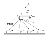
- FIG. 1 is a diagram showing an overview of a measurement system S.
- the measurement system S is a marine geophysical exploration system for analyzing sub-seafloor geological structures.
- seismic waves are generated from a seismic source 2 such as an air gun or a sparker, and a data processing device 1 analyzes the sub-seafloor geological structure using the results of measurements of the seismic waves by a number of measuring devices 4 installed on the seabed.
- the measurement system S comprises a data processing device 1, a seismic source 2, an optical communication device 3, and a number of measurement devices 4.
- the data processing device 1, the seismic source 2, and the optical communication device 3 are mounted on a ship 100 capable of moving on the ocean.
- the multiple measurement devices 4 are installed on the seabed at intervals of at least a predetermined distance.
- the data processing device 1 is, for example, a computer, which acquires measurement data indicating the vibration state of the seabed observed by multiple measuring devices 4 at the time when seismic waves are emitted, and analyzes the acquired measurement data. That is, the data processing device 1 analyzes the measurement data of the measuring devices 4 installed on the seabed and the seismic waves detected by the measuring devices 4 in response to the emission of seismic waves from a seismic source 2 toward the seabed from a ship sailing on the sea during a measurement period. As shown in FIG. 1A, the data processing device 1 controls the multiple measuring devices 4 by sending and receiving acoustic signals, and receives the measurement data generated by the multiple measuring devices 4. The data processing device 1 also acquires information indicating absolute time from, for example, a PTP network or a GPS (Global Positioning System).
- GPS Global Positioning System
- the seismic source 2 generates seismic waves during the measurement period.
- the seismic source 2 generates seismic waves, for example, under the control of the data processing device 1, but may also generate seismic waves under the control of a control device different from the data processing device 1 (for example, a computer installed on a ship different from the ship 100).
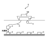
- the optical communication device 3 acquires measurement data from at least one measuring device 4 by optically communicating with it based on the control of the data processing device 1.
- the optical communication device 3 emits a first optical signal to the measuring device 4 underwater, and receives a second optical signal transmitted by the measuring device 4 that has received the first optical signal.
- the optical communication device 3 is connected to the data processing device 1 by a cable C, and, based on the control of the data processing device 1, it dives to a position where it can perform optical communication with the measuring device 4, and then performs optical communication with the measuring device 4.
- the optical communication device 3 moves sequentially to the vicinity of multiple measuring devices 4, and acquires measurement data from the multiple measuring devices 4 sequentially.
- the measurement system S may have multiple optical communication devices 3, and the multiple optical communication devices 3 may acquire measurement data from the multiple measuring devices 4.
- the measuring device 4 generates measurement data indicating the amount of vibration of the measuring device 4.
- the measurement data indicates the amount of vibration of the measuring device 4 caused by seismic waves.
- the measurement data is data indicating the magnitude of vibration detected by a sensor possessed by the measuring device 4, and is, for example, data including a measurement value generated by sampling the signal output by the sensor every millisecond.
- the measurement data is associated with the internal time kept by an oscillator inside the measuring device 4.
- the measuring device 4 transmits the measurement data to the optical communication device 3 by an optical signal.
- the internal time of the measuring device 4 is different from the absolute time because it is measured by an oscillator built into the measuring device 4. Furthermore, due to the aging characteristics of the oscillator of the measuring device 4, the frequency of the oscillator changes over time. As a result, a difference occurs between the internal time that the measuring device 4 associates with the measurement data and the absolute time. Even if a chip-scale atomic clock (CSAC), which has relatively good aging characteristics, is used as the oscillator, a frequency offset occurs over time.
- CSAC chip-scale atomic clock
- the data processing device 1 therefore uses an acoustic signal or an optical signal to determine the time difference between the absolute time and the internal time in the measuring device 4 at the start and end of the measurement, and corrects the internal time associated with the measurement data based on the determined result. If the oscillator in the measuring device 4 has an approximately constant amount of change in frequency offset per unit time regardless of the passage of time, the time difference between the absolute time and the internal time at each measurement point within the measurement period also changes linearly. In other words, the time difference per unit time is approximately constant. The data processing device 1 uses this characteristic to calculate the difference between the internal time and the absolute time corresponding to each measurement value by multiplying the amount of change in the time difference per unit time by the time elapsed since the start of the measurement. The data processing device 1 corrects the internal time associated with the measurement data based on the calculated time difference.
- the data processing device 1 By operating the data processing device 1 in this manner, the data processing device 1 does not need to determine the time difference between the absolute time and the internal time of the measuring device 4 using an acoustic signal or optical signal continuously while the measuring device 4 is measuring, but only needs to determine the time difference between the start and end points of the measurement. Therefore, even if multiple measuring devices 4 are not connected to a PTP network, the data processing device 1 can analyze the measurement data with high accuracy without significantly reducing measurement efficiency.
- Measurements for analyzing the subseafloor geological structure are carried out periodically. For example, measurements are carried out over several days to several weeks once a year. If multiple measurement devices 4 are installed each time a measurement period is required, the installation work takes a lot of time, resulting in poor measurement efficiency. Therefore, the measurement system S in this embodiment is configured to have multiple measurement devices 4 installed in advance on the seabed measure seismic waves during multiple measurement periods spanning multiple years.
- the measuring device 4 runs on batteries, if it is installed on the seabed and operates for a long period of time, the battery will be depleted in a short time. Therefore, in the measurement system S, multiple measuring devices 4 are configured to start up at the start of a measurement period and stop measuring operation when the measurement period ends.
- the measuring device 4 that has stopped measuring operation enters a sleep state in which its oscillator is stopped to reduce power consumption, while maintaining the function of receiving acoustic signals from the data processing device 1.
- the measuring device 4 has, for example, a measurement state in which measurement is performed, a standby state in which the oscillator is operating and no measurement is being performed, and a sleep state in which the oscillator is stopped and no measurement is being performed.
- FIGS. 2 and 3 are diagrams for explaining the procedure for starting up multiple measuring devices 4.
- FIG. 2 shows a schematic diagram of multiple measuring devices 4 as viewed from above.
- the circles ( ⁇ ) shown in FIG. 2 indicate measuring devices 4 installed on the seabed.
- the numbers under the circles are identification information (ID) for identifying the measuring devices 4.
- ID identification information
- the data processing device 1 transmits an acoustic signal including control information to the measuring device 4 within the range reached by the acoustic signal (e.g., the range within the dashed frame in FIG. 2), thereby enabling the measuring device 4 to start a measurement operation.
- the data processing device 1 transmits a start command, a synchronization command, and a recording start command, thereby enabling the measuring device 4 to start a measurement operation.
- the dashed arrow in FIG. 2 represents a start command, and the solid arrow represents a synchronization command.
- the data processing device 1 may transmit parameters required for measurement (e.g., sampling interval or preamplifier gain) to the measuring device 4.
- the start-up command includes a character string corresponding to an instruction to transition the measuring device 4 from a sleep state to a state where it can measure, and the ID of the measuring device 4.
- the synchronization command includes a character string corresponding to an instruction to request the internal time of the measuring device 4, and the ID of the measuring device 4.
- the data processing device 1 may send a synchronization command including an absolute time recognized by the data processing device 1.
- synchronization the process in which the data processing device 1 determines the relationship between the absolute time and the internal time of the measuring device 4 based on the internal time received from the measuring device 4 by sending a synchronization command to the measuring device 4 is referred to as "synchronization".
- the start recording command includes a character string corresponding to an instruction to start recording measurement data, and the ID of the measuring device 4.
- a measuring device 4 with no letter in a circle shown in Figure 2 (for example, a measuring device 4 with an ID of 0606) is in a stopped state.
- a measuring device 4 with a "W” in a dashed circle indicates that it has received a startup command and is currently executing startup processing.
- a measuring device 4 with a "W” in a solid circle indicates that it has completed startup, but synchronization has not yet been completed.
- a measuring device 4 with an "S” in a dashed circle indicates that it has received a synchronization command and is currently executing synchronization processing.
- a measuring device 4 with an "S” in a solid circle indicates that synchronization has been completed.
- FIG. 3 is a diagram showing an example of a management table indicating the state of each measuring device 4.
- the ID of the measuring device 4 information indicating whether startup has been completed, information indicating whether synchronization has been completed, the previous action (i.e., the action executed immediately before), and the time at which the action was executed are associated with each other.
- the data processing device 1 sends startup commands and synchronization commands to different measuring devices 4 in a time-division manner.
- the data processing device 1 transmits a synchronization command to the already started second measuring device 4 during the period from when the start-up command is transmitted to the first measuring device 4 until the start-up of the first measuring device 4 is completed.
- the multiple measuring devices 4 can be brought into a state in which they can measure in a shorter time than if the start-up command was transmitted to the measuring device 4 and then the measuring device 4 waited until the measuring device 4 started up.
- the measuring devices 4 can be brought into a state in which they can measure reliably in a shorter time than if a person were to start up each measuring device 4.
- the data processing device 1 also activates multiple measuring devices 4 while proceeding in a fixed direction. As an example, as shown in FIG. 2, the data processing device 1 transmits an activation command to multiple measuring devices 4 located in front of the ship 100, and transmits a synchronization command to the multiple measuring devices 4 after the ship 100 moves to a position ahead of the activated multiple measuring devices 4.
- the data processing device 1 transmits commands to multiple measuring devices 4 located at the front of the vessel 100 on which the data processing device 1 is mounted and capable of receiving acoustic signals, and to multiple measuring devices 4 located at the rear of the vessel 100 and capable of receiving acoustic signals.
- the data processing device 1 can bring multiple measuring devices 4 into a state where they can make measurements in a shorter time than if commands were sent only to measuring devices 4 located either at the front or rear of the vessel 100.
- the data processing device 1 may send a recording start command to the measurement device 4 that has completed synchronization after receiving a response to the synchronization command from the measurement device 4 and completing synchronization.
- the recording start command may be a command that includes an instruction to start recording immediately, or may be a command that indicates the time to start recording.
- the data processing device 1 may send recording start commands continuously to multiple measurement devices 4 after synchronization of all measurement devices 4 is completed and before the seismic source generates seismic waves.
- the data processing device 1 sequentially starts up and synchronizes the multiple measuring devices 4 before a measurement period, and when the measurement period ends, the measuring devices 4 go into sleep mode to reduce battery consumption. Because the measurement system S is configured in this way, it is possible to have multiple measuring devices 4 measure seismic waves efficiently over a long period of time.
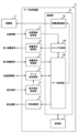
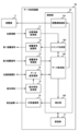
- [Configuration of data processing device 1] 4 is a diagram showing the configuration of the data processing device 1.
- the data processing device 1 has a position information acquisition unit 11, an acoustic signal transmission unit 12, an acoustic signal reception unit 13, a data transmission/reception unit 14, an absolute time acquisition unit 15, an external communication unit 16, a storage unit 17, and a control unit 18.
- the control unit 18 has a seismic source control unit 181, a command creation unit 182, a data acquisition unit 183, a time difference identification unit 184, and a correction unit 185. Note that some of the functional units of the control unit 18 may be provided in a device other than the data processing device 1.
- the location information acquisition unit 11 acquires location information indicating the location of the data processing device 1, i.e., the location of the ship 100 on which the data processing device 1 is mounted.
- the location information acquisition unit 11 acquires, for example, radio waves received from a GPS satellite as location information, and identifies the latitude and longitude based on the acquired location information.
- the location information acquisition unit 11 notifies the command creation unit 182 of the identified latitude and longitude.
- the acoustic signal transmitting unit 12 is an acoustic communication unit that transmits a first acoustic signal to the measuring device 4.
- the acoustic signal transmitting unit 12 transmits a first acoustic signal including control data (e.g., various commands) input from the command creating unit 182 based on the control of the command creating unit 182.
- the acoustic signal receiving unit 13 transmits a first acoustic signal including a command to a measuring device 4 within a predetermined range from the position of the ship 100 indicated by the position information acquired by the position information acquiring unit 11 by referring to the respective positions of the multiple measuring devices 4 stored in the memory unit 17.
- the predetermined range is a range within which the measuring device 4 can receive the first acoustic signal transmitted by the acoustic signal transmitting unit 12.
- the acoustic signal transmitting unit 12 transmits a first acoustic signal including a startup command, which is startup data for starting up the measuring device 4, to each of the multiple measuring devices 4.
- the acoustic signal transmitting unit 12 transmits a first acoustic signal including a synchronization command indicating absolute time (i.e., a synchronization command including time data) to a measuring device 4 from which the acoustic signal receiving unit 13 has received a second acoustic signal including response data to the startup command.
- the acoustic signal transmitting unit 12 also transmits a first acoustic signal including a recording start command, which is recording start data indicating an instruction to start recording measurement data, to a measuring device 4 from which the acoustic signal receiving unit 13 has received a response to the first acoustic signal including a synchronization command.
- the acoustic signal transmitting unit 12 transmits a first acoustic signal including recording start data to a measuring device 4 that has transmitted response data to the synchronization command.
- the acoustic signal transmitting unit 12 may transmit a recording start command including the ID of one measuring device 4, or may transmit a recording start command including the IDs of multiple measuring devices 4 that have completed synchronization.
- the acoustic signal transmitting unit 12 may transmit a recording start command including information indicating that the command is intended for all measuring devices 4.
- the acoustic signal receiving unit 13 is an acoustic communication unit that receives a second acoustic signal emitted by the measuring device 4 that has received the first acoustic signal.
- the acoustic signal receiving unit 13 receives, for example, the second acoustic signal indicating the internal time of the measuring device 4.
- the acoustic signal receiving unit 13 identifies the internal time based on the time data included in the received acoustic signal, and notifies the data acquisition unit 183 of the identified internal time.
- the data transmission/reception unit 14 is a communication interface for transmitting and receiving data with the optical communication device 3.
- the data transmission/reception unit 14 transmits data input from the data acquisition unit 183 to the optical communication device 3, including an instruction to acquire the internal time from the measurement device 4, and receives time data indicating the internal time acquired by the optical communication device 3 from the measurement device 4.
- the data transmitter/receiver 14 may notify the optical communication device 3 of the absolute time acquired by the absolute time acquisition unit 15, and receive time data in which the internal time is associated with the absolute time at the time when the optical communication device 3 acquired the internal time from the measurement device 4.
- the data transmitter/receiver 14 receives data indicating the internal time acquired by the optical communication device 3 from the measurement device 4 at a time within a specified range from the time when the last measurement is performed in the measurement period.
- the data transmitter/receiver 14 notifies the data acquisition unit 183 of the acquired time data.
- the absolute time acquisition unit 15 acquires absolute time, for example, from a GPS satellite.
- the absolute time acquisition unit 15 notifies the acquired absolute time to the time difference determination unit 184.
- the absolute time acquisition unit 15 may also notify the data transmission/reception unit 14 of the absolute time.
- the external communication unit 16 transmits the measurement results, including the measurement data after the internal time has been corrected, input from the correction unit 185.
- the external communication unit 16 may transmit the measurement results to an external computer that executes a process of analyzing the measurement results and identifying the sub-seafloor geological structure, or may transmit the measurement results to another processing unit included in the control unit 18.
- the memory unit 17 has storage media such as a ROM (Read Only Memory), a RAM (Random Access Memory), and an SSD (Solid State Drive).
- the memory unit 17 stores programs executed by the control unit 18.
- the memory unit 17 also stores various data for causing the multiple measuring devices 4 to perform measurements.
- the memory unit 17 stores, for example, the position of each of the multiple measuring devices 4 in association with the identification information of the measuring device 4. Specifically, the memory unit 17 stores the latitude and longitude of the measuring devices 4 in association with the IDs of the multiple measuring devices 4.
- the storage unit 17 also stores a management table such as that shown in FIG. 3. Furthermore, the storage unit 17 stores multiple pieces of measurement data acquired from the measurement devices 4 in association with the IDs of the multiple measurement devices 4. The storage unit 17 stores multiple pieces of measurement data in association with the internal time of the measurement device 4 at the time the measurement data was generated. After that, when the time corrected from the internal time by the correction unit 185 is associated with the measurement data, the storage unit 17 stores the measurement data in association with the corrected time.
- the control unit 18 has, for example, a CPU (Central Processing Unit).
- the control unit 18 executes the programs stored in the storage unit 17, thereby functioning as an epicenter control unit 181, a command creation unit 182, a data acquisition unit 183, a time difference determination unit 184, and a correction unit 185.
- a CPU Central Processing Unit
- the epicenter control unit 181 transmits an instruction to generate seismic waves to the epicenter 2.
- the epicenter control unit 181 causes the epicenter 2 to generate seismic waves, for example, after the acoustic signal transmission unit 12 transmits a first acoustic signal including a recording start command to the multiple measuring devices 4.
- the epicenter control unit 181 transmits an instruction to generate seismic waves to the epicenter 2, for example, after receiving a notification from the data acquisition unit 183 that all measuring devices 4 are ready to perform measurements.
- the epicenter control unit 181 may cause the epicenter 2 to generate seismic waves at a predetermined date and time, or may cause the epicenter 2 to generate seismic waves in response to receiving an instruction from an external device.
- the data processing device 1 may not have the epicenter control unit 181, and an external control device may function as the epicenter control unit 181.
- the command creation unit 182 creates commands to be sent by the acoustic signal transmission unit 12 to the measuring device 4.
- the command creation unit 182 creates, for example, a startup command, a synchronization command, and a recording start command, and inputs the created commands to the acoustic signal transmission unit 12.
- the command creation unit 182 selects a measuring device 4 within a predetermined range from the latitude and longitude input from the position information acquisition unit 11 by referring to the latitude and longitude of the locations where multiple measuring devices 4 are installed that are stored in the memory unit 17.
- the command creation unit 182 creates a command that includes the ID of the selected measuring device 4.
- the command creation unit 182 creates a startup command for a measuring device 4 in a sleep state among multiple measuring devices 4 within a predetermined range.
- the command creation unit 182 creates a synchronization command for that measuring device 4.
- the command creation unit 182 creates a recording start command for that measuring device 4.
- the command creation unit 182 When the command creation unit 182 inputs the created command to the acoustic signal transmission unit 12, it updates the "last action" in the management table stored in the memory unit 17. When the command creation unit 182 inputs a start-up command to the acoustic signal transmission unit 12, it sets the “last action” corresponding to the ID of the measuring device 4 included in the start-up command to "starting up.” When the command creation unit 182 inputs a synchronization command to the acoustic signal transmission unit 12, it sets the "last action” corresponding to the ID of the measuring device 4 included in the synchronization command to "synchronizing.”
- the data acquisition unit 183 acquires various data transmitted from the measuring device 4.
- the data acquisition unit 183 acquires response data to a command transmitted by the acoustic signal transmission unit 12 via the acoustic signal reception unit 13.
- the data acquisition unit 183 notifies the command creation unit 182 that the response data has been acquired.
- the data acquisition unit 183 When the data acquisition unit 183 acquires response data, it updates the contents of the "most recent action" in the management table stored in the storage unit 17. When the data acquisition unit 183 acquires response data indicating startup, for example, it updates the "most recent action" corresponding to the ID of the measuring device 4 included in the response data to "startup completed.” When the data acquisition unit 183 acquires response data including the internal time of the measuring device 4 sent by the measuring device 4 in response to receiving a synchronization command, it updates the "most recent action” corresponding to the ID of the measuring device 4 included in the response data to "synchronization completed.” The data acquisition unit 183 associates the absolute time when the synchronization command was sent and the internal time indicated by the response data with the ID of the measuring device 4 and stores them in the storage unit 17.
- the data acquisition unit 183 acquires response data indicating that the measuring device 4 has started recording, it updates the "last action" corresponding to the ID of the measuring device 4 contained in the response data to "start recording”.
- the data acquisition unit 183 receives response commands to the start recording command from all measuring devices 4, that is, when the "last action" of all measuring devices 4 has become “start recording”, it notifies the epicenter control unit 181 that measurement can start.
- the data acquisition unit 183 may further acquire the emission time, which is the absolute time when the optical communication device 3 emits the first optical signal, and the internal time included in the second optical signal received by the optical communication device 3.
- the second optical signal is an optical signal transmitted by the measurement device 4 in response to receiving the first optical signal.
- the data acquisition unit 183 associates the emission time and the internal time with the ID of the measurement device 4, stores them in the memory unit 17, and notifies the time difference determination unit 184.
- the data acquisition unit 183 acquires measurement data from the measuring device 4 via the data transmission/reception unit 14.
- the data acquisition unit 183 acquires multiple pieces of measurement data each indicating a measurement value corresponding to a different time. For example, after the measurement period ends, the data acquisition unit 183 acquires multiple pieces of measurement data collected from the measuring device 4 by the optical communication device 3 through optical communication from the data transmission/reception unit 14.
- the data acquisition unit 183 associates the acquired measurement data with the ID of the measuring device 4 and stores it in the memory unit 17, thereby enabling the time difference identification unit 184 to refer to the measurement data.
- the time difference determination unit 184 refers to the measurement data stored in the memory unit 17 to determine the time difference between the absolute time and the internal time of the measurement device 4 associated with the measurement data. Specifically, the time difference determination unit 184 refers to the absolute time and internal time stored in the memory unit 17 in association with the ID of the measurement device 4 to determine a first time difference, which is the difference between the start absolute time when the measurement period starts and the internal time of the measurement device 4 associated with the measurement data at the time when the measurement period starts. In addition, the time difference determination unit 184 determines a second time difference, which is the difference between the end absolute time when the measurement period ends and the internal time associated with the measurement data at the time when the measurement period ends.
- the time difference determination unit 184 determines at least one of the first time difference and the second time difference based on the difference between the absolute time when the acoustic signal transmission unit 12 transmitted the first acoustic signal and the internal time indicated by the second acoustic signal received by the acoustic signal reception unit 13.
- the time difference determination unit 184 determines the first time difference based on the difference between the absolute time transmitted by the command creation unit 182 in the synchronization command and the internal time of the measurement device 4 included in the response data to the synchronization command, for example.
- the time difference determination unit 184 also determines the second time difference based on the difference between the absolute time included in the measurement data acquisition request command transmitted by the optical communication device 3 to the measurement device 4 after the measurement period ends and the internal time of the measurement device 4 included in the response data to the measurement data acquisition request command.
- the absolute time at the time when the measuring device 4 receives the first acoustic signal differs from the absolute time at which the acoustic signal transmitting unit 12 transmits the first acoustic signal.
- the time difference determining unit 184 may determine at least one of the first time difference and the second time difference based on the difference between the time obtained by adding the time required for the first acoustic signal to reach the measuring device 4 to the absolute time at which the acoustic signal transmitting unit 12 transmits the first acoustic signal and the internal time indicated by the second acoustic signal received by the acoustic signal receiving unit 13.
- the time difference determination unit 184 may determine at least either the first time difference or the second time difference based on the difference between the internal time indicated by the second acoustic signal and the time obtained by adding the time required for the measurement device 4 to determine the internal time after receiving the first acoustic signal to the absolute time when the acoustic signal transmission unit 12 transmitted the first acoustic signal. In this way, the time difference determination unit 184 uses the propagation time of the first acoustic signal and the processing time in the measurement device 4, thereby improving the accuracy of determining the difference between the absolute time and the internal time.
- the time difference determination unit 184 may determine both the first time difference and the second time difference based on the difference between the absolute time when the acoustic signal transmitting unit 12 transmits the first acoustic signal and the internal time included in the second acoustic signal received by the acoustic signal receiving unit 13, but may also determine at least one of them based on the difference between the light emission time, which is the absolute time when the optical communication device 3 transmits the first optical signal, and the internal time included in the second optical signal received by the optical communication device 3 from the measurement device 4.
- the time difference determination unit 184 may determine at least one of the first time difference and the second time difference based on the difference between the absolute time when the optical communication device 3 transmits the first optical signal plus the time it takes for the first optical signal to reach the measurement device 4 and the internal time indicated by the second optical signal received by the optical communication device 3.
- the absolute time when the optical communication device 3 transmits the first optical signal may be the time when the data transmission/reception unit 14 instructs the optical communication device 3 to transmit the first optical signal.
- the optical communication device 3 emits the first optical signal at a position closer to the measurement device 4 than the data processing device 1. Therefore, the propagation time required for the first optical signal emitted by the optical communication device 3 to reach the measurement device 4 is shorter than the propagation time required for the first acoustic signal transmitted by the acoustic signal transmitter 12 to reach the measurement device 4, and therefore there is less variation in the propagation time. As a result, the accuracy of determining the time difference is improved by using an optical signal to determine the time difference.
- the time difference determination unit 184 determines the first time difference using an acoustic signal at the start of the measurement, and determines the second time difference using an optical signal at the end of the measurement when the optical communication device 3 moves close to the measurement device 4 to collect the measurement data. By operating in this manner, the time difference determination unit 184 can determine the time difference with high accuracy based on the optical signal without increasing the time that the optical communication device 3 spends moving to obtain the internal time, thereby achieving both measurement efficiency and measurement accuracy.
- the correction unit 185 reads out the multiple pieces of measurement data stored in the memory unit 17, and corrects the internal times associated with the multiple pieces of measurement data based on at least the first time difference and the second time difference.
- the correction unit 185 stores the multiple pieces of measurement data with the corrected internal times in the memory unit 17.
- the correction unit 185 determines the amount of change per unit time in the difference between the absolute time and the internal time based on the time difference between the absolute start time, which is the absolute time when the measurement starts, and the absolute end time, which is the absolute time when the measurement ends, and the difference between the first time difference and the second time difference.
- the correction unit 185 corrects the internal times associated with the multiple measurement data based on the determined amount of change.
- the correction unit 185 determines the difference between the internal time and the absolute time at the internal time corresponding to the measurement data to be corrected by adding to the first time difference the value obtained by multiplying the elapsed time from the start absolute time to the internal time by the amount of change per unit time.
- the correction unit 185 corrects the internal time of the measurement data to be corrected based on the determined difference. In this way, if the amount of change per unit time in the frequency offset of the oscillator possessed by the measurement device 4 is approximately constant regardless of the passage of time, the time difference determination unit 184 can efficiently correct the internal time corresponding to the measurement data using the first time difference at the start of measurement and the second time difference at the end of measurement.
- the data acquisition unit 183 may also send a synchronization command during the measurement period to acquire the internal time of the measurement device 4, and the correction unit 185 may correct the internal time of the measurement data based on the difference between the absolute time during the measurement period and the internal time of the measurement device 4.
- the correction unit 185 may also correct the internal time of the measurement data based on the time difference between the internal time and the absolute time identified based on the synchronization command issued at a number of points corresponding to the linearity of the aging characteristics of the oscillator possessed by the measurement device 4. By operating in this manner, the correction unit 185 can appropriately correct the internal time corresponding to the measurement data in accordance with the aging characteristics of the oscillator possessed by the measurement device 4.
- FIG. 5 is a diagram showing the configuration of the measuring device 4.
- the measuring device 4 has an oscillator 41, a sensor 42, an acoustic signal receiving unit 43, an acoustic signal transmitting unit 44, an optical signal receiving unit 45, an optical signal transmitting unit 46, a storage unit 47, and a control unit 48.
- the control unit 48 has a data creating unit 481 and a data communication unit 482.
- the oscillator 41 generates an oscillation signal used to keep internal time in the measuring device 4.
- the oscillator 41 is, for example, a chip-scale atomic oscillator, but may be another type of oscillator.
- the sensor 42 generates a detection signal whose level changes according to the vibration of the measuring device 4.
- the sensor 42 inputs the detection signal to the data creation unit 481.
- the acoustic signal receiving unit 43 receives a first acoustic signal transmitted from the data processing device 1.
- the acoustic signal receiving unit 43 inputs data such as the command and absolute time contained in the received first acoustic signal to the data communication unit 482.
- the acoustic signal transmitting unit 44 transmits a second acoustic signal indicating the internal time at which the first acoustic signal was received to the data processing device 1.
- the optical signal receiving unit 45 receives a first optical signal transmitted from the optical communication device 3.
- the optical signal receiving unit 45 inputs data such as commands and absolute time contained in the received first optical signal to the data communication unit 482.
- the optical signal transmitting unit 46 transmits a second optical signal indicating the internal time at which the first optical signal was received.
- the optical signal transmitting unit 46 transmits the second optical signal including the internal time input from the data communication unit 482, for example, to the optical communication device 3.
- the storage unit 47 has storage media such as ROM, RAM, and SSD.
- the storage unit 47 stores the programs executed by the control unit 48.
- the storage unit 47 also stores the measurement data created by the data creation unit 481.
- the control unit 48 has, for example, a CPU.
- the control unit 48 functions as a data creation unit 481 and a data communication unit 482 by executing a program stored in the storage unit 47.
- the data creation unit 481 functions as a measurement data creation unit that creates multiple pieces of measurement data associated with the internal time measured based on the oscillator 41.
- the data creation unit 481 creates multiple pieces of measurement data indicating the sampled signal level (i.e., the measurement value) by, for example, sampling the detection signal input from the sensor 42 at a predetermined time interval (for example, 1 millisecond intervals).
- the data creation unit 481 associates the multiple pieces of measurement data with the internal time and stores them in the memory unit 47.
- the data creation unit 481 may measure the internal time by counting the oscillation signal input from the oscillator 41, or may identify the internal time based on data indicating the internal time input from the oscillator 41.
- the data communication unit 482 transmits, via the acoustic signal transmission unit 44, response data to a command contained in the first acoustic signal received from the data processing device 1 via the acoustic signal reception unit 43.
- the data communication unit 482 also transmits, via the optical signal transmission unit 46, response data to a command contained in the optical signal received from the optical communication device 3 via the optical signal reception unit 45.
- the data communication unit 482 receives a synchronization command, it acquires the internal time at the time the synchronization command was received from the oscillator 41 or the data creation unit 481, and transmits response data including the acquired internal time.
- the data communication unit 482 also transmits the multiple pieces of measurement data created by the data creation unit 481 to the optical communication device 3 via the optical signal transmission unit 46. Specifically, the data communication unit 482 transmits the multiple pieces of measurement data stored in the storage unit 47 in association with the internal time.
- Fig. 6 and Fig. 7 are diagrams for explaining the aging characteristics of an oscillator.
- Fig. 6 shows the characteristics of an oscillator whose aging characteristics are worse than those of oscillator 41
- Fig. 7 shows the aging characteristics of oscillator 41.
- Fig. 6A and Fig. 7A show the characteristics in the initial state
- Fig. 6B and Fig. 7B show the characteristics after a long period of time (several years) has passed.
- the horizontal axis in Figures 6 and 7 indicates the number of days that have passed since the start of measurement.
- the thin solid line in Figures 6 and 7 indicates the amount of clock drift (left vertical axis).
- the thick solid line indicates a state in which the amount of clock drift changes linearly over time, and the correction unit 185 corrects the internal time corresponding to multiple measurement data under the assumption that the amount of clock drift changes as indicated by the thick solid line.
- the dashed line indicates the residual error (right vertical axis) after the correction unit 185 corrects the internal time. The residual error is greatest near the center of the measurement period, and in Figure 6, a maximum residual error of approximately 0.44 milliseconds occurs.
- the residual error is approximately 0.009 milliseconds, and it can be seen that the internal time corresponding to the measurement data is corrected with high accuracy by the correction process of the correction unit 185.
- the process of correcting the internal time corresponding to the measurement data during the measurement period based on the first time difference at the start of the measurement and the second time difference at the end of the measurement is particularly effective.
- FIG. 8 is a diagram illustrating the difference between calculating the second time difference using an acoustic signal at the end of the measurement and calculating the second time difference using an optical signal.
- the solid line indicates the amount of clock drift, and the dashed line indicates the maximum and minimum values of the error due to correction.
- FIG. 8A shows a case where the time difference is determined based on the acoustic signal at the start and end of the measurement.
- FIG. 8B shows a case where the first time difference is determined based on the acoustic signal at the start of the measurement, and the second time difference is determined based on the optical signal at the end of the measurement.
- the measurement system S may be configured to calibrate the frequency of the oscillator 41 when the measurement period ends.
- FIG. 9 is a diagram showing the configuration of a measuring device 4 capable of calibrating the frequency.
- the measuring device 4 shown in FIG. 9 differs from the measuring device 4 shown in FIG. 5 in that it further includes a calibration unit 483, but is otherwise the same.
- correction unit 185 determines the frequency deviation of the oscillator of measurement device 4 at the end of the measurement period based on the first time difference and the second time difference, and notifies measurement device 4 of the determined frequency deviation.
- Correction unit 185 calculates the amount of internal time deviation per unit time, for example, by dividing the difference between the first time difference and the second time difference by the measurement period. Since the amount of internal time deviation per unit time is proportional to the magnitude of the frequency deviation, correction unit 185 can calculate the frequency deviation based on the amount of internal time deviation per unit time.
- the calibration unit 483 calibrates the frequency of the oscillator 41 based on the frequency deviation notified from the data processing device 1. Specifically, the calibration unit 483 changes the voltage of a control signal used to control the oscillation frequency of the oscillator 41 according to the frequency deviation. When the frequency deviation is, for example, +1.0 ⁇ 10-10 , the control voltage is changed so as to lower the oscillation frequency of the oscillator 41 by a frequency equivalent to the frequency deviation of 1.0 ⁇ 10-10 .
- the calibration unit 483 may calibrate the frequency of the oscillator 41 when the frequency deviation at the time when the measurement period ends is equal to or greater than a threshold value.
- the calibration unit 483 may calibrate the frequency of the oscillator 41 using the average value of the time difference between the absolute time transmitted by the optical communication device 3 via an optical signal and the internal time at the time when the measurement device 4 receives the optical signal, obtained multiple times over a certain period of time (e.g., 10 minutes).
- FIG. 10 is a diagram for explaining the calibration of the frequency of oscillator 41 by calibration unit 483.
- FIG. 10 it is assumed that there is a measurement period of 40 days per year.
- FIG. 10 it is shown that the frequency offset becomes large while oscillator 41 is operating, and that the frequency offset does not change while oscillator 41 is stopped.
- the error bars extending above and below the black dot indicating the frequency offset indicate the error range (magnitude of instability) caused by the power cycle.
- Fig. 10A shows the change in frequency deviation when the calibration unit 483 does not calibrate the frequency of the oscillator 41.
- Fig. 10B shows the change in frequency deviation when the calibration unit 483 calibrates the frequency of the oscillator 41 when the frequency deviation becomes +3.0 ⁇ 10 -10 or more.
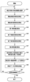
- Figures 11 to 13 are flowcharts showing the flow of processing in the data processing device 1.
- Figures 11 and 12 show the flow of processing from the start to the end of measurement in one measurement period.
- Figure 13 shows the flow of correction processing of the internal time corresponding to the measurement data.
- the flowchart shown in FIG. 11 starts from the point when all the measuring devices 4 are in a sleep state.
- the command creation unit 182 monitors whether the timing to start the measuring devices 4, i.e., whether the measurement period has arrived (S11). If the command creation unit 182 determines that the measurement period has arrived (YES in S11), it selects a measuring device 4 that is within a predetermined range from the position of the ship 100 and is in a sleep state (S12). The command creation unit 182 transmits a start-up command to the selected measuring device 4 (S13).
- the command creation unit 182 selects a measurement device 4 that is within a predetermined range from the position of the ship 100 and for which synchronization has not been completed (S14).
- the command creation unit 182 transmits a synchronization command to the selected measurement device 4 (S15).
- the time difference determination unit 184 determines the first time difference based on the relationship between the internal time and the absolute time at which the command creation unit 182 sent the synchronization command.
- the time difference determination unit 184 associates the determined first time difference with the ID of the measurement device 4 and stores it in the storage unit 17 (S16).
- the time difference determination unit 184 may not determine the first time difference at this point, and the data acquisition unit 183 may associate the absolute time at which the synchronization command was sent with the internal time received from the measurement device 4 and store them in the storage unit 17.
- the command creation unit 182 sends a recording start command to the measuring device 4 that received the response data to the synchronization command (S17).
- the command creation unit 182 refers to the management table stored in the memory unit 17 and determines whether synchronization of all measuring devices 4 is complete and preparations for recording measurement data are complete (S18). If preparations for all measuring devices 4 are not complete (NO in S18), the command creation unit 182 repeats the processes from S12 to S17. If preparations for all measuring devices 4 are complete (YES in S18), the command creation unit 182 notifies the epicenter control unit 181 that preparations for measurement are complete, and the epicenter control unit 181 generates seismic waves in the epicenter 2 (S19).
- the epicenter control unit 181 generates seismic waves in the epicenter 2 until the last scheduled measurement is completed (NO in S20). When the last scheduled measurement is completed (YES in S20), the epicenter control unit 181 notifies the command creation unit 182 that the measurement has been completed.
- the command creation unit 182 sends a recording end command to the measuring device 4 via the data transmission/reception unit 14 (S21).
- the measuring device 4 that has received the recording end command ends recording of the measurement data and transitions to a standby state.
- the data acquisition unit 183 acquires multiple pieces of measurement data via the optical communication device 3 (S22).
- the data acquisition unit 183 stores the acquired multiple pieces of measurement data in the memory unit 17, associating them with the ID of the measuring device 4.
- the data acquisition unit 183 also acquires, via the data transmission/reception unit 14, the absolute time at the time when the optical communication device 3 requests the internal time from the measurement device 4 in response to the end of the measurement, and the internal time acquired by the optical communication device 3 from the measurement device 4 (S23).
- the time difference determination unit 184 determines a second time difference based on the absolute time at the time when the measurement was completed acquired by the data acquisition unit 183 and the internal time of the measurement device 4 at that time (S24).
- the time difference determination unit 184 associates the determined second time difference with the ID of the measurement device 4 and stores it in the storage unit 17.
- the correction unit 185 analyzes the multiple pieces of measurement data.
- the correction unit 185 corrects the internal time associated with the multiple pieces of measurement data based on the first time difference and the second time difference stored in the memory unit 17 in association with the ID of the common measurement device 4 (S25).
- the correction unit 185 outputs the measurement result including the multiple pieces of measurement data after correction (S26).
- FIG. 13 is a flowchart showing the flow of the measurement data correction process (S25).
- the correction unit 185 selects a measurement device 4 for which measurement data is to be corrected (S31).
- the method by which the correction unit 185 selects the measurement device 4 is arbitrary, and the correction unit 185 selects, for example, in the order of the IDs of the measurement devices 4.
- the correction unit 185 then identifies the absolute start time stored in the storage unit 17 in association with the ID of the selected measurement device 4 (S32).
- the correction unit 185 also identifies the internal start time corresponding to the absolute start time (S33).
- the correction unit 185 calculates the first time difference based on the absolute start time and the internal start time (S34). As described above, the correction unit 185 may calculate the first time difference based further on the time required from when the position information acquisition unit 11 transmits a first acoustic signal including a synchronization command until the first acoustic signal reaches the measurement device 4.
- the correction unit 185 identifies the end absolute time and the end internal time stored in the memory unit 17 in association with the ID of the selected measurement device 4 (S35, S36). The correction unit 185 calculates the second time difference based on the end absolute time and the end internal time (S37). The correction unit 185 may calculate the second time difference based further on the time required from when the position information acquisition unit 11 transmits a first optical signal to request the internal time until the first optical signal reaches the measurement device 4.
- the correction unit 185 calculates the amount of change ⁇ T per unit time in the difference between the absolute time and the internal time based on the first time difference and the second time difference (S38). Specifically, the correction unit 185 calculates the amount of change ⁇ T by dividing the difference between the first time difference and the second time difference by the elapsed time from the start absolute time to the end absolute time.
- the correction unit 185 calculates a correction value corresponding to each internal time by multiplying the elapsed time from the measurement start internal time to the internal time when each piece of measurement data was acquired by the unit amount ⁇ T (S39).
- the correction unit 185 calculates a corrected internal time by adding the calculated correction value to the internal time when each piece of measurement data was acquired.
- the correction unit 185 corrects the time corresponding to the measurement data by updating the internal time of each piece of measurement data corresponding to the selected measurement device 4 to the corrected internal time (S40).
- the correction unit 185 may correct the internal time corresponding to all of the measurement data, or may correct the internal time corresponding to a portion of the measurement data necessary to analyze the seismic waves.
- the correction unit 185 associates the measurement data with the corrected time and stores them in the memory unit 17.
- the correction unit 185 repeats the processes from S31 to S40. If the correction of the measurement data of all the measuring devices 4 has been completed (YES in S41), the correction unit 185 ends the correction process.
- the data processing device 1 includes a time difference specifying unit 184 that specifies a first time difference, which is the difference between the internal time and the absolute start time when the measurement period starts, and a second time difference, which is the difference between the internal time and the absolute end time when the measurement period ends, and a correction unit 185 that corrects the internal time associated with a plurality of measurement data based on the first time difference and the second time difference.
- the data processing device 1 can specify the relationship between the seismic waves and the seismic waves detected by the measurement device 4 with high accuracy, with almost no effect on the time required for measurement, even if the measurement device 4 is not connected to the PTP network and cannot recognize the absolute time.
- the data processing device 1 identifies the first and second time differences, but the measurement device 4 may identify the first and second time differences and correct the internal time associated with the measurement data.
- the measurement device 4 creates measurement data associated with the corrected internal time (i.e., a time approximately equal to absolute time), and the data processing device 1 can obtain the measurement data associated with the corrected internal time.
- FIG. 14 is a diagram showing the configuration of a data processing device 1A according to this modified example.
- FIG. 15 is a diagram showing the configuration of a measurement device 4A according to this modified example.
- FIG. 16 is a flowchart showing the processing flow in the data processing device 1A according to this modified example.
- FIG. 17 is a flowchart showing the processing flow in the measurement device 4A according to this modified example.
- Data processing device 1A differs from data processing device 1 in that it does not have the time difference determination unit 184 and correction unit 185 that data processing device 1 shown in FIG. 4 has.
- the functions of each unit shown in FIG. 14 are equivalent to the functions of each unit with the same reference numerals in data processing device 1 shown in FIG. 4.
- the data acquisition unit 183 acquires the measurement data whose internal time has been corrected in the measurement device 4 via the data transmission/reception unit 14.
- the time associated with the measurement data acquired by the data acquisition unit 183 is almost equal to the absolute time, and can therefore be used as is for analysis. Therefore, the data acquisition unit 183 transmits the measurement results, including the acquired measurement data, to the outside via the external communication unit 16.
- the measurement device 4A differs from the measurement device 4 in that, in addition to the configuration of the measurement device 4 shown in FIG. 5, the measurement device 4A has a time difference determination unit 484 and a correction unit 485.
- the measurement device 4A may further have the calibration unit 483 shown in FIG. 9.
- the data communication unit 482 When the data communication unit 482 acquires a synchronization command via the acoustic signal receiving unit 43, the data communication unit 482 notifies the time difference determination unit 484 of the absolute time included in the synchronization command.
- the time difference determination unit 484 determines the time difference between the internal time at that time and the notified absolute time as the first time difference at the start of measurement.
- the time difference determination unit 484 stores the determined first time difference in the memory unit 47.
- the data communication unit 482 when the data communication unit 482 acquires the absolute time at the time when the measurement ends via the acoustic signal receiving unit 43 or the optical signal receiving unit 45, the data communication unit 482 notifies the time difference determination unit 484 of the acquired absolute time.
- the time difference determination unit 484 determines the time difference between the internal time at that time and the notified absolute time as the second time difference at the time when the measurement ends.
- the time difference determination unit 484 stores the determined second time difference in the memory unit 47.
- the time difference determination unit 484 can execute the same processing as the time difference determination unit 184. For example, the time difference determination unit 484 calculates a first time difference based on the difference between the absolute time and the internal time and the propagation time for the first acoustic signal transmitted from the data processing device 1A to reach the measurement device 4A. The time difference determination unit 484 also calculates a second time difference based on the difference between the absolute time and the internal time and the propagation time for the first optical signal transmitted from the optical communication device 3 to reach the measurement device 4A.
- the correction unit 485 corrects the internal time at which the sensor 42 outputs the measurement data, based on the first time difference and second time difference identified by the time difference identification unit 484. Similar to the correction unit 185, the correction unit 485 identifies the amount of change per unit time in the difference between the absolute time and the internal time, based on the time difference between the start absolute time, which is the absolute time at which the measurement starts, and the end absolute time, which is the absolute time at which the measurement ends, and the difference between the first time difference and the second time difference. Next, the correction unit 485 corrects the internal time associated with the multiple measurement data created by the data creation unit 481, based on the identified amount of change. The correction unit 485 notifies the data communication unit 482 of the corrected internal time, in association with the measurement data.
- the data communication unit 482 transmits the multiple pieces of measurement data associated with the corrected internal time notified by the correction unit 485 to the optical communication device 3 via the optical signal transmission unit 46.
- the flowchart of data processing device 1A shown in FIG. 16 shows the process flow from the start of measurement in one measurement period to when data processing device 1A acquires measurement data.
- the processes from S11 to S20 in the flowchart shown in FIG. 16 differ from the flowchart shown in FIG. 11 in that there is no process (S16) for identifying the first time difference, but are otherwise the same.
- the flowchart of the measuring device 4A shown in FIG. 17 starts from the point when the data processing device 1 transmits a first acoustic signal including a synchronization command.
- the time difference determining unit 484 determines the absolute time included in the synchronization command as the start absolute time (S42).
- the time difference determining unit 484 also determines the internal time at this point in time as the start internal time (S43).
- the time difference determining unit 484 calculates the difference between the start absolute time and the start internal time as the first time difference (S44).
- the measurement device 4A measures seismic waves (S45), and the data creation unit 481 creates measurement data associated with the internal time output by the oscillator 41.
- the optical signal receiving unit 45 receives a first optical signal including absolute time from the optical communication device 3 (S46).
- the time difference determination unit 484 determines the absolute time included in the first optical signal as the end absolute time (S47).
- the time difference determination unit 484 also determines the internal time at this point as the end internal time (S48).
- the time difference determination unit 484 calculates the difference between the end absolute time and the end internal time as the second time difference (S49).
- the correction unit 485 calculates the amount of change ⁇ T per unit time in the difference between the absolute time and the internal time based on the first time difference and the second time difference (S50). Specifically, the correction unit 485 calculates the amount of change ⁇ T by dividing the difference between the first time difference and the second time difference by the elapsed time from the start absolute time to the end absolute time.
- the correction unit 485 then calculates a correction value corresponding to each internal time by multiplying the elapsed time from the measurement start internal time to the internal time when each piece of measurement data was acquired by a unit amount ⁇ T (S51).
- the correction unit 485 calculates a corrected internal time by adding the calculated correction value to the internal time when each piece of measurement data was acquired.
- the correction unit 185 corrects the time corresponding to the measurement data by updating the internal time of each piece of measurement data to the corrected internal time (S52).
- the correction unit 485 may correct the internal time corresponding to all of the measurement data, or may correct the internal time corresponding to a portion of the measurement data required to analyze seismic waves.
- the correction unit 485 inputs the measurement data associated with the corrected time to the data communication unit 482.
- the data communication unit 482 transmits the measurement data with the corrected time to the optical communication device 3 via the optical signal transmission unit 46 (S53).
- Fig. 18 is a diagram showing the configuration of a data processing device 1B according to the second modification.
- Fig. 19 is a diagram showing the configuration of a measurement device 4B according to the second modification.
- the second modification is different from the data processing device 1A according to the first modification in that the data processing device 1B has a correction unit 185.
- the measurement device 4A has a time difference specifying unit 484 and a correction unit 485, but in the second modification, the measurement device 4B has a time difference specifying unit 484 and does not have a correction unit 485.
- the time difference determination unit 484 of the measurement device 4B operates together with the time difference determination unit 484 of the measurement device 4A. That is, the time difference determination unit 484 calculates a first time difference based on the difference between the absolute time and the internal time and the propagation time for the first acoustic signal transmitted from the data processing device 1A to reach the measurement device 4A. The time difference determination unit 484 also calculates a second time difference based on the difference between the absolute time and the internal time and the propagation time for the first optical signal transmitted from the optical communication device 3 to reach the measurement device 4A. The time difference determination unit 484 inputs the determined first time difference and second time difference to the data communication unit 482.
- the data creation unit 481 of the measurement device 4B also associates the multiple pieces of measurement data output by the sensor 42 with the internal time and inputs them to the data communication unit 482.
- the data communication unit 482 associates the multiple pieces of measurement data with the internal time and transmits them to the data processing device 1B via the optical signal transmission unit 46, and also transmits the first time difference and second time difference identified by the time difference identification unit 484 to the data processing device 1B.
- correction unit 185 corrects the internal times associated with each of the multiple measurement data, similar to data processing device 1. In this way, it is optional whether the time difference determination unit and correction unit are provided in the data processing device or the measurement device.
- Data processing device 2 Source 3 Optical communication device 4 Measurement device 11 Position information acquisition unit 12 Acoustic signal transmission unit 13 Acoustic signal reception unit 14 Data transmission/reception unit 15 Absolute time acquisition unit 16 External communication unit 17 Memory unit 18 Control unit 41 Oscillator 42 Sensor 43 Acoustic signal reception unit 44 Acoustic signal transmission unit 45 Optical signal reception unit 46 Optical signal transmission unit 47 Memory unit 48 Control unit 100 Ship 181 Source control unit 182 Command creation unit 183 Data acquisition unit 184 Time difference determination unit 185 Correction unit 481 Data creation unit 482 Data communication unit 483 Calibration unit 484 Time difference determination unit 485 Correction unit
Landscapes
- Physics & Mathematics (AREA)
- Life Sciences & Earth Sciences (AREA)
- Engineering & Computer Science (AREA)
- Remote Sensing (AREA)
- General Physics & Mathematics (AREA)
- Environmental & Geological Engineering (AREA)
- Geology (AREA)
- General Life Sciences & Earth Sciences (AREA)
- Acoustics & Sound (AREA)
- Geophysics (AREA)
- Electromagnetism (AREA)
- Computer Networks & Wireless Communication (AREA)
- Signal Processing (AREA)
- Oceanography (AREA)
- Geophysics And Detection Of Objects (AREA)
- Optical Communication System (AREA)
Abstract
データ処理装置1は、海を航行する船舶から海底に向けて測定期間において発震源から震動波が発せられたことに応じて、海底に設置された測定装置4が検出した地震波に基づいて測定装置4が生成し、測定装置4で計時された内部時刻に関連付けられた複数の測定データを取得するデータ取得部183と、(1)測定期間が開始した時点の開始絶対時刻と、測定期間が開始した時点における測定データに関連付けられた内部時刻との差である第1時刻差、及び(2)測定期間が終了した時点の終了絶対時刻と、測定期間が終了した時点における測定データに関連付けられた内部時刻との差である第2時刻差、を特定する時刻差特定部184と、少なくとも第1時刻差及び第2時刻差に基づいて、複数の測定データに関連付けられた内部時刻を補正する補正部185と、を有する。
Description
本発明は、測定システム、データ処理装置、測定装置、データ処理方法及びプログラムに関する。
海底に設置された地震探査設備を用いて海底の震動を測定するシステムが知られている。特許文献1には、地震探査設備をPTP(Precision Time Protocol)ネットワークにケーブルで接続することにより、地震探査設備が正確な時刻を認識できるようにすることで、測定装置におけるクロックドリフトの影響が測定結果に及ばないようにする技術が開示されている。
多数の測定装置を海底に設置して、それぞれの測定装置で測定を行う場合、多数の測定装置をPTPネットワークにケーブルで接続すると、ケーブルの配線コストが大きくなってしまうという問題があった。
そこで、本発明はこれらの点に鑑みてなされたものであり、海底に設置された測定装置の測定結果におけるクロックドリフトの影響を軽減することを目的とする。
本発明の第1の態様の測定システムは、海底に設置された測定装置と、海を航行する船舶から海底に向けて測定期間において発震源から震動波が発せられたことに応じて前記測定装置が検出した地震波の測定データを解析するデータ処理装置と、を備える。前記測定装置は、計時に使用される発振器と、前記発振器に基づいて計時された内部時刻に関連付けられた複数の前記測定データを作成する測定データ作成部と、を有する。前記測定装置又は前記データ処理装置のいずれかが、(1)前記測定期間が開始した時点の開始絶対時刻と、前記測定期間が開始した時点における前記測定データに関連付けられた前記内部時刻との差である第1時刻差、及び(2)前記測定期間が終了した時点の終了絶対時刻と、前記測定期間が終了した時点における前記測定データに関連付けられた前記内部時刻との差である第2時刻差、を特定する時刻差特定部と、少なくとも前記第1時刻差及び前記第2時刻差に基づいて、前記複数の測定データに関連付けられた前記内部時刻を補正する補正部と、を有する。
前記補正部は、前記開始絶対時刻と前記終了絶対時刻との時間差と、前記第1時刻差と前記第2時刻差との差と、に基づいて、単位時間あたりの絶対時刻と前記内部時刻との差の変化量を特定し、特定した前記変化量に基づいて前記複数の測定データに関連付けられた前記内部時刻を補正してもよい。
前記補正部は、前記第1時刻差に、前記開始絶対時刻から前記内部時刻までの経過時間に前記変化量を乗算した値を加算することにより、前記内部時刻における絶対時刻と前記内部時刻との差を特定し、特定した差に基づいて前記内部時刻を補正してもよい。
前記データ処理装置は、絶対時刻を含む第1音響信号を送信する信号送信部をさらに有し、前記測定装置は、前記第1音響信号を受信する音響信号受信部をさらに有し、前記時刻差特定部は、前記第1音響信号が示す絶対時刻と、前記測定装置が前記第1音響信号を受信した時点における前記内部時刻との差に基づいて、前記第1時刻差及び前記第2時刻差の少なくともいずれかを特定してもよい。
前記時刻差特定部は、前記第1音響信号が示す絶対時刻に、前記第1音響信号が前記測定装置に到達するまでに要する時間を加算した時刻と、前記測定装置が前記第1音響信号を受信した時点における前記内部時刻と、の差に基づいて、前記第1時刻差及び前記第2時刻差の少なくともいずれかを特定してもよい。
前記測定システムは、海中で前記測定装置に絶対時刻を示す第1光信号を発する光通信装置をさらに有し、前記測定装置は、前記光通信装置が発した前記第1光信号を受信する光信号受信部をさらに有し、前記時刻差特定部は、前記光通信装置が前記第1光信号を発した発光時刻と、前記測定装置が前記第1光信号を受信した時点における前記内部時刻との差に基づいて、前記第1時刻差及び前記第2時刻差の少なくともいずれかを特定してもよい。
前記測定システムは、海中で前記測定装置に絶対時刻を示す第1光信号を発する光通信装置をさらに有し、前記データ処理装置は、前記測定装置を制御するための制御データを含む第1音響信号を送信する信号送信部をさらに有し、前記測定装置は、前記光通信装置が発した前記第1光信号を受信する光信号受信部と、をさらに有し、前記第1音響信号を受信する音響信号受信部と、をさらに有し、前記時刻差特定部は、前記信号送信部が前記第1音響信号を送信した絶対時刻と、前記測定装置が前記第1音響信号を受信した時点における前記内部時刻との差に基づいて、前記第1時刻差を特定し、前記光通信装置が前記第1光信号を発した発光時刻と、前記測定装置が前記第1光信号を受信した時点における前記内部時刻との差に基づいて前記第2時刻差を特定してもよい。
前記補正部は、前記第1時刻差及び前記第2時刻差に基づいて、前記測定期間が終了した時点における前記測定装置の前記発振器の周波数偏差を特定し、特定した前記周波数偏差を前記測定装置に通知し、前記測定装置は、前記データ処理装置から通知された前記周波数偏差に基づいて前記発振器の周波数を校正する校正部をさらに有してもよい。
前記測定システムは、それぞれ異なる位置に設置された複数の前記測定装置を有し、前記データ処理装置は、前記測定装置を制御するための制御データを含む第1音響信号を送信する信号送信部と、前記第1音響信号を受信した前記測定装置が発した第2音響信号を受信する信号受信部と、をさらに有し、前記信号送信部は、複数の前記測定装置それぞれに対して、前記測定装置を起動させるための起動データを含む前記第1音響信号を送信し、前記起動データに対する応答データを含む前記第2音響信号を前記信号受信部が受信した前記測定装置に対して、時刻データを含む前記第1音響信号を送信してもよい。
前記データ処理装置は、前記船舶に搭載されており、複数の前記測定装置それぞれの位置と前記測定装置の識別情報とを関連付けて記憶する記憶部と、前記船舶の位置を示す位置情報を取得する位置情報取得部と、を有し、前記信号送信部は、前記記憶部に記憶された複数の前記測定装置それぞれの位置を参照することにより、前記位置情報が示す位置から所定の範囲内にある前記測定装置に対して前記時刻データを含む前記第1音響信号を送信してもよい。
前記信号送信部は、前記時刻データを含む前記第1音響信号に対する応答を前記信号受信部が受信した前記測定装置に対して、測定データの記録を開始する指示を示す記録開始データを含む前記第1音響信号を送信してもよい。
前記測定システムは、前記信号送信部が複数の前記測定装置に対して前記記録開始データを含む前記第1音響信号を送信した後に、前記震動波を発生できる状態になったことを前記発震源に通知する制御装置をさらに有してもよい。
本発明の第2の態様のデータ処理装置は、海を航行する船舶から海底に向けて測定期間において発震源から震動波が発せられたことに応じて、海底に設置された測定装置が検出した地震波を示す複数の測定データであって、前記測定装置が生成し、前記測定装置で計時された内部時刻に関連付けられた複数の測定データを取得するデータ取得部と、(1)前記測定期間が開始した時点の開始絶対時刻と、前記測定期間が開始した時点における前記測定データに関連付けられた前記内部時刻との差である第1時刻差、及び(2)前記測定期間が終了した時点の終了絶対時刻と、前記測定期間が終了した時点における前記測定データに関連付けられた前記内部時刻との差である第2時刻差、を特定する時刻差特定部と、少なくとも前記第1時刻差及び前記第2時刻差に基づいて、前記複数の測定データに関連付けられた前記内部時刻を補正する補正部と、を有する。
本発明の第3の態様の測定装置は、海を航行する船舶から海底に向けて測定期間において発震源から震動波が発せられたことに応じて生じる地震波を海底で測定する測定装置であって、前記測定装置で計時された内部時刻に関連付けられた複数の測定データを作成するデータ作成部と、(1)前記測定期間が開始した時点の開始絶対時刻と、前記測定期間が開始した時点における前記測定データに関連付けられた前記内部時刻との差である第1時刻差、及び(2)前記測定期間が終了した時点の終了絶対時刻と、前記測定期間が終了した時点における前記測定データに関連付けられた前記内部時刻との差である第2時刻差、を特定する時刻差特定部と、少なくとも前記第1時刻差及び前記第2時刻差に基づいて、前記複数の測定データに関連付けられた前記内部時刻を補正する補正部と、を有する。
本発明の第4の態様のデータ処理方法は、コンピュータが実行する、海を航行する船舶から海底に向けて測定期間において発震源から震動波が発せられたことに応じて、海底に設置された測定装置が検出した地震波を示す複数の測定データであって、前記測定装置が生成し、前記測定装置で計時された内部時刻に関連付けられた複数の測定データを取得するステップと、(1)前記測定期間が開始した時点の開始絶対時刻と、前記測定期間が開始した時点における前記測定データに関連付けられた前記内部時刻との差である第1時刻差、及び(2)前記測定期間が終了した時点の終了絶対時刻と、前記測定期間が終了した時点における前記測定データに関連付けられた前記内部時刻との差である第2時刻差、を特定するステップと、少なくとも前記第1時刻差及び前記第2時刻差に基づいて、前記複数の測定データに関連付けられた前記内部時刻を補正するステップと、を有する。
本発明の第5の態様のプログラムは、コンピュータに、海を航行する船舶から海底に向けて測定期間において発震源から震動波が発せられたことに応じて、海底に設置された測定装置が検出した地震波を示す複数の測定データであって、前記測定装置が生成し、前記測定装置で計時された内部時刻に関連付けられた複数の測定データを取得するステップと、(1)前記測定期間が開始した時点の開始絶対時刻と、前記測定期間が開始した時点における前記測定データに関連付けられた前記内部時刻との差である第1時刻差、及び(2)前記測定期間が終了した時点の終了絶対時刻と、前記測定期間が終了した時点における前記測定データに関連付けられた前記内部時刻との差である第2時刻差、を特定するステップと、少なくとも前記第1時刻差及び前記第2時刻差に基づいて、前記複数の測定データに関連付けられた前記内部時刻を補正するステップと、を実行させるためのプログラムである。
本発明によれば、海底に設置された測定装置の測定結果のクロックドリフトの影響を軽減することができるという効果を奏する。
[測定システムSの概要]
図1は、測定システムSの概要を示す図である。測定システムSは、海底下地質構造を解析するための海洋物理探査システムである。測定システムSにおいては、エアガン又はスパーカー等の発震源2から震動波を発生し、海底に設置された多数の測定装置4が震動波を測定した結果を用いてデータ処理装置1が海底下地質構造を解析する。
図1は、測定システムSの概要を示す図である。測定システムSは、海底下地質構造を解析するための海洋物理探査システムである。測定システムSにおいては、エアガン又はスパーカー等の発震源2から震動波を発生し、海底に設置された多数の測定装置4が震動波を測定した結果を用いてデータ処理装置1が海底下地質構造を解析する。
測定システムSは、データ処理装置1と、発震源2と、光通信装置3と、複数の測定装置4と、を備える。データ処理装置1、発震源2及び光通信装置3は、海洋を移動可能な船舶100に搭載されている。複数の測定装置4は、所定の距離以上の間隔で海底に設置されている。
データ処理装置1は、例えばコンピュータであり、震動波が発せられたタイミングで複数の測定装置4において観測された海底の震動状態を示す測定データを取得し、取得した測定データを解析する。すなわち、データ処理装置1は、海底に設置された測定装置4と、海を航行する船舶から海底に向けて測定期間において発震源2から震動波が発せられたことに応じて測定装置4が検出した地震波の測定データを解析する。図1Aに示すように、データ処理装置1は、音響信号を送受信することにより、複数の測定装置4を制御するとともに、複数の測定装置4が生成した測定データを受信する。また、データ処理装置1は、例えばPTPネットワーク又はGPS(Global Positioning System)から絶対時刻を示す情報を取得する。
発震源2は、測定期間中に震動波を発生させる。発震源2は、例えばデータ処理装置1の制御に基づいて震動波を発生させるが、データ処理装置1と異なる制御装置(例えば船舶100と異なる船に搭載されたコンピュータ)の制御に基づいて震動波を発生させてもよい。
光通信装置3は、データ処理装置1の制御に基づいて少なくとも1つの測定装置4との間で光通信をすることにより、測定装置4から測定データを取得する。光通信装置3は、海中で測定装置4に第1光信号を発し、第1光信号を受信した測定装置4が送信した第2光信号を受信する。光通信装置3は、ケーブルCによりデータ処理装置1と接続されており、データ処理装置1の制御に基づいて、測定装置4との間で光通信をすることができる位置まで潜航した後に、測定装置4との間で光通信をする。光通信装置3は、複数の測定装置4の近傍まで順次移動し、複数の測定装置4から測定データを順次取得する。なお、測定システムSが複数の光通信装置3を有しており、複数の光通信装置3が複数の測定装置4から測定データを取得してもよい。
測定装置4は、測定装置4の振動量を示す測定データを生成する。測定データは、震動波に起因する測定装置4の振動量を示す。測定データは、測定装置4が有するセンサが検出した振動の大きさを示すデータであり、例えば、センサが出力する信号を1ミリ秒ごとにサンプリングすることにより生成された測定値を含むデータである。測定データは測定装置4の内部の発振器により計時された内部時刻に関連付けられている。測定装置4は、光信号により光通信装置3に測定データを送信する。
ところで、測定装置4の内部時刻は測定装置4が内蔵する発振器により計時された時刻なので、絶対時刻と異なっている。さらに、測定装置4が有する発振器のエージング特性の影響で、発振器の周波数は時間の経過に伴って変化する。その結果、測定装置4が測定データに関連付ける内部時刻と絶対時刻との間には差が生じる。発振器として、エージング特性が比較的良好なチップスケール原子発振器(CSAC:Chip Scale Atomic Clock)を使用したとしても、時間の経過に伴って周波数オフセットが生じてしまう。絶対時刻と内部時刻との間に差があると、発震源2が震動波を発したタイミングと測定データが示す地震波のタイミングとの関係を高い精度で特定することができないため、地震波に基づく海底下地質構造の解析精度が低下してしまうという問題が生じる。
そこで、データ処理装置1は、測定開始時点と測定終了時点において、音響信号又は光信号を用いて絶対時刻と測定装置4における内部時刻との時刻差を特定し、特定した結果に基づいて、測定データに関連付けられている内部時刻を補正する。測定装置4が有する発振器が、時間の経過によらず、単位時間あたりの周波数オフセットの変化量がほぼ一定である場合、測定期間内の各測定時点における絶対時刻と内部時刻との間の時刻差も線形に変化する。すなわち、単位時間あたりの時刻差がほぼ一定である。データ処理装置1は、この特徴を利用して、測定開始時点からの経過時間に単位時間あたりの時刻差の変化量を乗算することにより、それぞれの測定値に対応する内部時刻と絶対時刻との差を算出する。データ処理装置1は、算出した時刻の差に基づいて、測定データに関連付けられている内部時刻を補正する。
データ処理装置1がこのように動作することにより、データ処理装置1は、測定装置4が測定中に継続的に音響信号又は光信号を用いて絶対時刻と測定装置4における内部時刻との時刻差を特定する必要がなく、測定開始時点と測定終了時点における時刻差を特定すればよい。したがって、複数の測定装置4がPTPネットワークに接続されていないとしても、測定効率を大きく低下させることなくデータ処理装置1が測定データを高い精度で解析することができる。
[測定装置4の起動手順]
海底下地質構造を解析するための測定は、定期的に実施される。例えば、1年ごとに数日から数週間にわたって測定が実施される。測定を実施する期間が到来するたびに複数の測定装置4を設置すると、設置作業に多大な時間を要するため測定効率が悪い。そこで、本実施形態における測定システムSは、複数年にわたる複数の測定期間において、予め海底に設置された複数の測定装置4に地震波を測定させるように構成されている。
海底下地質構造を解析するための測定は、定期的に実施される。例えば、1年ごとに数日から数週間にわたって測定が実施される。測定を実施する期間が到来するたびに複数の測定装置4を設置すると、設置作業に多大な時間を要するため測定効率が悪い。そこで、本実施形態における測定システムSは、複数年にわたる複数の測定期間において、予め海底に設置された複数の測定装置4に地震波を測定させるように構成されている。
測定装置4はバッテリーにより動作するので、長期間にわたって海底に設置された状態で動作していると、バッテリーが短時間で消耗してしまう。そこで、測定システムSにおいては、測定期間を開始する時点で複数の測定装置4が起動し、測定期間が終了すると複数の測定装置4が測定動作を停止するように構成されている。測定動作を停止した測定装置4は、データ処理装置1からの音響信号を受信する機能を維持しつつ、測定装置4が有する発振器を停止させて消費電力を抑えたスリープ状態になる。測定装置4は、例えば、測定を実行する測定状態、発振器が動作しており、かつ測定を実行していないスタンバイ状態、及び発振器が停止しており、かつ測定を実行していないスリープ状態を有する。
図2及び図3は、複数の測定装置4を起動する手順について説明するための図である。図2は、複数の測定装置4を上方から見た状態を模式的に示している。図2に示す円(〇)は、海底に設置された測定装置4を示している。円の下の数字は、測定装置4を識別するため識別情報(ID)である。
データ処理装置1は、船舶100が移動している間に、音響信号が到達する範囲(例えば図2における破線の枠内の範囲)の測定装置4に対して制御情報を含む音響信号を送信することにより、測定装置4が測定動作を開始できる状態にする。具体的には、データ処理装置1は、起動コマンド、同期コマンド及び記録開始コマンドを送信することにより、測定装置4が測定動作を開始できる状態にする。図2における破線の矢印は起動コマンドを表しており、実線の矢印は同期コマンドを表している。データ処理装置1は、測定に必要なパラメータ(例えばサンプリング間隔又はプリアンプゲイン)を測定装置4に送信してもよい。
起動コマンドには、スリープ状態から測定可能な状態に測定装置4を遷移させる指示に対応する文字列と測定装置4のIDとが含まれる。同期コマンドには、測定装置4の内部時刻を要求する指示に対応する文字列と測定装置4のIDとが含まれる。データ処理装置1は、データ処理装置1が認識している絶対時刻を含む同期コマンドを送信してもよい。以下の説明において、データ処理装置1が、同期コマンドを測定装置4に送信することにより測定装置4から受信した内部時刻に基づいて、絶対時刻と測定装置4の内部時刻との関係を特定する処理を「同期」という。記録開始コマンドには、測定データの記録を開始する指示に対応する文字列と測定装置4のIDとが含まれる。
図2に示す円の中に文字が記載されていない測定装置4(例えばIDが0606の測定装置4)は、動作を停止している状態である。破線の円の中に「W」が記載されている測定装置4は、起動コマンドを受信し、起動処理を実行中であることを示している。実線の円の中に「W」が記載されている測定装置4は、起動が完了した状態であるが、同期が完了していない状態を示している。破線の円の中に「S」が記載されている測定装置4は、同期コマンドを受信し、同期処理を実行中であることを示している。実線の中に「S」が記載されている測定装置4は、同期が完了した状態を示している。
図3は、それぞれの測定装置4の状態を示す管理テーブルの一例を示す図である。図3に示す管理テーブルにおいては、測定装置4のIDと、起動が完了したか否かを示す情報と、同期が完了したか否かを示す情報と、直前アクション(すなわち、直前に実行されたアクション)と、当該アクションが行われた時刻とが関連付けられている。図2における破線領域内の複数の測定装置4の状態、及び図3の管理テーブルにおける時刻からわかるように、データ処理装置1は、起動コマンドの送信と同期コマンドを時分割で異なる測定装置4に送信している。
具体的には、データ処理装置1は、第1の測定装置4に起動コマンドを送信してから第1の測定装置4の起動が完了までの間に、起動済の第2の測定装置4に同期コマンドを送信する。データ処理装置1がこのように複数の測定装置4を順次起動させてから同期させることで、測定装置4に起動コマンドを送信してから当該測定装置4が起動するまで待機する場合よりも短時間で複数の測定装置4を測定できる状態にすることができる。また、人がそれぞれの測定装置4を起動させる場合に比べて、短時間で確実に測定装置4を測定できる状態にすることができる。
また、データ処理装置1は、一定の向きに進行しながら複数の測定装置4を起動させる。一例として、図2に示すように、データ処理装置1は、船舶100の前方にある複数の測定装置4に起動コマンドを送信し、起動した複数の測定装置4よりも前の位置に船舶100が移動した後に、当該複数の測定装置4に同期コマンドを送信する。
このように、データ処理装置1は、データ処理装置1を搭載する船舶100の前方にあり、かつ音響信号を受信できる複数の測定装置4と、船舶100の後方にあり、かつ音響信号を受信できる複数の測定装置4とにコマンドを送信する。データ処理装置1がこのように動作することで、船舶100の前方又は後方のいずれか一方にある測定装置4のみにコマンドを送信する場合に比べて短時間で複数の測定装置4を測定可能な状態にすることができる。
なお、図2及び図3には示していないが、データ処理装置1は、同期コマンドに対する応答を測定装置4から受信して同期が完了した後に、同期が完了した測定装置4に対して記録開始コマンドを送信してもよい。記録開始コマンドは、すぐに記録を開始する指示を含むコマンドであってもよく、記録を開始する時刻を示すコマンドであってもよい。データ処理装置1は、全ての測定装置4の同期が完了した後でありかつ発震源が震動波を発生する前に、複数の測定装置4に連続的に記録開始コマンドを送信してもよい。
測定を行うたびに多数の測定装置4を海底に設置すると、設置のための時間と費用が多大になる。一方、長期間にわたって測定装置4を動作状態にしておくと、バッテリーが消耗してしまうという問題が生じる。測定システムSにおいては、測定期間の前に、データ処理装置1が複数の測定装置4を順次起動して同期させ、測定期間が終了すると、測定装置4をスリープ状態にしてバッテリーの消耗を抑制する。測定システムSがこのように構成されていることで、長期間にわたって効率良く多数の測定装置4に地震波を測定させることができる。
[データ処理装置1の構成]
図4は、データ処理装置1の構成を示す図である。データ処理装置1は、位置情報取得部11と、音響信号送信部12と、音響信号受信部13と、データ送受信部14と、絶対時刻取得部15と、外部通信部16と、記憶部17と、制御部18と、を有する。制御部18は、発震源制御部181と、コマンド作成部182と、データ取得部183と、時刻差特定部184と、補正部185と、を有する。なお、制御部18が有する機能部の一部が、データ処理装置1以外の装置に設けられていてもよい。
図4は、データ処理装置1の構成を示す図である。データ処理装置1は、位置情報取得部11と、音響信号送信部12と、音響信号受信部13と、データ送受信部14と、絶対時刻取得部15と、外部通信部16と、記憶部17と、制御部18と、を有する。制御部18は、発震源制御部181と、コマンド作成部182と、データ取得部183と、時刻差特定部184と、補正部185と、を有する。なお、制御部18が有する機能部の一部が、データ処理装置1以外の装置に設けられていてもよい。
位置情報取得部11は、データ処理装置1の位置、すなわちデータ処理装置1が搭載された船舶100の位置を示す位置情報を取得する。位置情報取得部11は、例えばGPS衛星から受信した電波を位置情報として取得し、取得した位置情報に基づいて、緯度・経度を特定する。位置情報取得部11は、特定した緯度・経度をコマンド作成部182に通知する。
音響信号送信部12は、測定装置4に対して第1音響信号を送信する音響通信ユニットである。音響信号送信部12は、例えば、コマンド作成部182の制御に基づいて、コマンド作成部182から入力された制御データ(例えば各種のコマンド)を含む第1音響信号を送信する。音響信号受信部13は、記憶部17に記憶された複数の測定装置4それぞれの位置を参照することにより、位置情報取得部11が取得した位置情報が示す船舶100の位置から所定の範囲内にある測定装置4に対してコマンドを含む第1音響信号を送信する。所定の範囲は、音響信号送信部12が送信した第1音響信号を測定装置4が受信可能な範囲である。
一例として、音響信号送信部12は、複数の測定装置4それぞれに対して、測定装置4を起動させるための起動データである起動コマンドを含む第1音響信号を送信する。音響信号送信部12は、起動コマンドに対する応答データを含む第2音響信号を音響信号受信部13が受信した測定装置4に対して、絶対時刻を示す同期コマンド(すなわち時刻データを含む同期コマンド)を含む第1音響信号を送信する。
また、音響信号送信部12は、同期コマンドを含む第1音響信号に対する応答を音響信号受信部13が受信した測定装置4に対して、測定データの記録を開始する指示を示す記録開始データである記録開始コマンドを含む第1音響信号を送信する。すなわち、音響信号送信部12は、同期コマンドに対する応答データを送信した測定装置4に対して、記録開始データを含む第1音響信号を送信する。
音響信号送信部12は、1つの測定装置4のIDを含む記録開始コマンドを送信してもよく、同期を完了した複数の測定装置4のIDを含む記録開始コマンドを送信してもよい。音響信号送信部12は、全ての測定装置4を対象とするコマンドであることを示す情報を含む記録開始コマンドを送信してもよい。このような記録開始コマンドを音響信号送信部12が送信することで、記録開始コマンドを1回送信することにより、複数の測定装置4に震動波の記録を開始させることができるので、測定効率が向上する。
音響信号受信部13は、第1音響信号を受信した測定装置4が発した第2音響信号を受信する音響通信ユニットである。音響信号受信部13は、例えば、測定装置4の内部時刻を示す第2音響信号を受信する。音響信号受信部13は、受信した音響信号に含まれる時刻データに基づいて内部時刻を特定し、特定した内部時刻をデータ取得部183に通知する。
データ送受信部14は、光通信装置3との間でデータを送受信するための通信インターフェースである。データ送受信部14は、例えば、データ取得部183から入力された、測定装置4から内部時刻を取得する指示を含むデータを光通信装置3に送信し、光通信装置3が測定装置4から取得した内部時刻を示す時刻データを受信する。
データ送受信部14は、絶対時刻取得部15が取得した絶対時刻を光通信装置3に通知し、光通信装置3が測定装置4から内部時刻を取得した時点の絶対時刻と内部時刻とが関連付けられた時刻データを受信してもよい。データ送受信部14は、例えば、測定期間内の最後の測定が行われる時点から所定の範囲内の時点で光通信装置3が測定装置4から取得した内部時刻を示すデータを受信する。データ送受信部14は、取得した時刻データをデータ取得部183に通知する。
絶対時刻取得部15は、例えばGPS衛星から絶対時刻を取得する。絶対時刻取得部15は、取得した絶対時刻を時刻差特定部184に通知する。絶対時刻取得部15は、絶対時刻をデータ送受信部14に通知してもよい。
外部通信部16は、補正部185から入力された、内部時刻を補正した後の測定データを含む測定結果を送信する。外部通信部16は、測定結果を解析して海底下地質構造を特定する処理を実行する外部のコンピュータに測定結果を送信してもよく、制御部18が有する他の処理部に送信してもよい。
記憶部17は、ROM(Read Only Memory)、RAM(Random Access Memory)及びSSD(Solid State Drive)等の記憶媒体を有する。記憶部17は、制御部18が実行するプログラムを記憶する。また、記憶部17は、複数の測定装置4に測定を実行させるための各種のデータを記憶する。記憶部17は、例えば、複数の測定装置4それぞれの位置と測定装置4の識別情報とを関連付けて記憶する。具体的には、記憶部17は、複数の測定装置4のIDに関連付けて、測定装置4の緯度・経度を記憶する。
また、記憶部17は、図3に示したような管理テーブルを記憶する。さらに、記憶部17は、複数の測定装置4のIDに関連付けて、測定装置4から取得した複数の測定データを記憶する。記憶部17は、測定データが生成された時点における測定装置4の内部時刻に関連付けて、複数の測定データを記憶する。その後、補正部185によって内部時刻から補正された時刻が測定データに関連付けられると、記憶部17は、補正後の時刻に関連付けて測定データを記憶する。
制御部18は、例えばCPU(Central Processing Unit)を有する。制御部18は、記憶部17に記憶されたプログラムを実行することにより、発震源制御部181、コマンド作成部182、データ取得部183、時刻差特定部184及び補正部185として機能する。
発震源制御部181は、震動波を発生する指示を発震源2に送信する。発震源制御部181は、例えば音響信号送信部12が複数の測定装置4に対して記録開始コマンドを含む第1音響信号を送信した後に、発震源2に震動波を発生させる。発震源制御部181は、例えば、全ての測定装置4が測定をできる状態になったという通知をデータ取得部183から受けた後に、震動波を発生する指示を発震源2に送信する。発震源制御部181は、予め定められた日時になると発震源2に震動波を発生させてもよく、外部装置から指示を受けたことに応じて発震源2に震動波を発生させてもよい。データ処理装置1が発震源制御部181を有しておらず、外部の制御装置が発震源制御部181として機能してもよい。
コマンド作成部182は、音響信号送信部12が測定装置4に送信するコマンドを作成する。コマンド作成部182は、例えば、起動コマンド、同期コマンド及び記録開始コマンドを作成し、作成したコマンドを音響信号送信部12に入力する。コマンド作成部182は、コマンドを作成する際、記憶部17に記憶された複数の測定装置4が設置された位置の緯度・経度を参照することにより、位置情報取得部11から入力された緯度・経度から所定の範囲内の測定装置4を選択する。コマンド作成部182は、選択した測定装置4のIDを含むコマンドを作成する。
図2を参照しながら説明したように、コマンド作成部182は、所定の範囲内の複数の測定装置4のうち、スリープ状態の測定装置4に対する起動コマンドを作成する。コマンド作成部182は、作成した起動コマンドに対応する測定装置4が起動したという通知をデータ取得部183から受けたことに応じて、当該測定装置4に対する同期コマンドを作成する。コマンド作成部182は、作成した同期コマンドに対応する測定装置4が同期を完了したという通知をデータ取得部183から受けたことに応じて、当該測定装置4に対する記録開始コマンドを作成する。
コマンド作成部182は、作成したコマンドを音響信号送信部12に入力すると、記憶部17に記憶された管理テーブルにおける「直前アクション」を更新する。コマンド作成部182は、起動コマンドを音響信号送信部12に入力すると、起動コマンドに含まれる測定装置4のIDに対応する「直前アクション」を「起動中」にする。コマンド作成部182は、同期コマンドを音響信号送信部12に入力すると、同期コマンドに含まれる測定装置4のIDに対応する「直前アクション」を「同期中」にする。
データ取得部183は、測定装置4から送信される各種のデータを取得する。データ取得部183は、音響信号受信部13を介して、音響信号送信部12が送信したコマンドに対する応答データを取得する。データ取得部183は、応答データを取得したことをコマンド作成部182に通知する。
データ取得部183は、応答データを取得した場合に、記憶部17に記憶された管理テーブルにおける「直前アクション」の内容を更新する。データ取得部183は、例えば起動したことを示す応答データを取得した場合に、当該応答データに含まれる測定装置4のIDに対応する「直前アクション」を「起動完了」に更新する。データ取得部183は、測定装置4が同期コマンドを受信したことに応じて送信した測定装置4の内部時刻を含む応答データを取得した場合に、当該応答データに含まれる測定装置4のIDに対応する「直前アクション」を「同期完了」に更新する。データ取得部183は、同期コマンドが送信された絶対時刻と応答データが示す内部時刻とを測定装置4のIDに関連付けて記憶部17に記憶させる。
データ取得部183は、測定装置4が記録を開始したことを示す応答データを取得した場合に、当該応答データに含まれる測定装置4のIDに対応する「直前アクション」を「記録開始」に更新する。データ取得部183は、記録開始コマンドに対する応答コマンドを全ての測定装置4から受信した場合、すなわち全ての測定装置4の「直前アクション」が「記録開始」になった場合、測定を開始可能であることを発震源制御部181に通知する。
また、データ取得部183は、光通信装置3が第1光信号を発した絶対時刻である発光時刻と、光通信装置3が受信した第2光信号に含まれている内部時刻と、をさらに取得してもよい。第2光信号は、第1光信号を受信したことに応じて測定装置4が送信した光信号である。データ取得部183は、発光時刻と内部時刻とを測定装置4のIDに関連付けて記憶部17に記憶させ、時刻差特定部184に通知する。
さらに、データ取得部183は、データ送受信部14を介して、測定装置4から測定データを取得する。データ取得部183は、それぞれ異なる時刻に対応する測定値を示す複数の測定データを取得する。データ取得部183は、例えば、測定期間が終了した後に、光通信装置3が光通信により測定装置4から回収した複数の測定データをデータ送受信部14から取得する。データ取得部183は、測定装置4のIDに関連付けて、取得した測定データを記憶部17に記憶させることにより、時刻差特定部184が測定データを参照できるようにする。
時刻差特定部184は、記憶部17に記憶された測定データを参照することにより、絶対時刻と、測定データに関連付けられた測定装置4の内部時刻と、の時刻差を特定する。具体的には、時刻差特定部184は、測定装置4のIDに関連付けて記憶部17に記憶された絶対時刻と内部時刻とを参照することにより、測定期間が開始した時点の開始絶対時刻と、測定期間が開始した時点における測定データに関連付けられた測定装置4の内部時刻との差である第1時刻差を特定する。また、測定期間が終了した時点の終了絶対時刻と、測定期間が終了した時点における測定データに関連付けられた内部時刻との差である第2時刻差を特定する。
時刻差特定部184は、音響信号送信部12が第1音響信号を送信した絶対時刻と、音響信号受信部13が受信した第2音響信号が示す内部時刻との差に基づいて、第1時刻差及び第2時刻差の少なくともいずれかを特定する。時刻差特定部184は、例えば、コマンド作成部182が同期コマンドで送信した絶対時刻と、同期コマンドに対する応答データに含まれている測定装置4の内部時刻との差に基づいて第1時刻差を特定する。また、時刻差特定部184は、測定期間が終了した後に、光通信装置3が測定装置4に送信した測定データ取得要求コマンドに含まれる絶対時刻と、測定データ取得要求コマンドに対する応答データに含まれている測定装置4の内部時刻との差に基づいて第2時刻差を特定する。
音響信号送信部12が第1音響信号を送信してから音響信号受信部13が第2音響信号を受信するまでの間に、音響信号の伝搬に要する時間がある。したがって、測定装置4が第1音響信号を受信した時点における絶対時刻は、音響信号送信部12が第1音響信号を送信した時点における絶対時刻と異なる。そこで、時刻差特定部184は、音響信号送信部12が第1音響信号を送信した絶対時刻に、第1音響信号が測定装置4に到達するまでに要する時間を加算した時刻と、音響信号受信部13が受信した第2音響信号が示す内部時刻と、の差に基づいて、第1時刻差及び第2時刻差の少なくともいずれかを特定してもよい。
時刻差特定部184は、音響信号送信部12が第1音響信号を送信した絶対時刻に、測定装置4が第1音響信号を受信してから内部時刻を特定するまでに要する時間をさらに加算した時刻と第2音響信号が示す内部時刻との差に基づいて、第1時刻差及び第2時刻差の少なくともいずれを特定してもよい。このように、時刻差特定部184が第1音響信号の伝搬時間及び測定装置4における処理時間を利用することで、絶対時刻と内部時刻との差の特定精度が向上する。
時刻差特定部184は、第1時刻差及び第2時刻差の両方を、音響信号送信部12が第1音響信号を送信した絶対時刻と音響信号受信部13が受信した第2音響信号に含まれる内部時刻との差に基づいて特定してもよいが、少なくともいずれかを、光通信装置3が第1光信号を送信した絶対時刻である発光時刻と光通信装置3が測定装置4から受信した第2光信号に含まれている内部時刻との差に基づいて特定してもよい。
時刻差特定部184は、光通信装置3が第1光信号を送信した絶対時刻に、第1光信号が測定装置4に到達するまでに要する時間を加算した時刻と、光通信装置3が受信した第2光信号が示す内部時刻と、の差に基づいて、第1時刻差及び第2時刻差の少なくともいずれかを特定してもよい。光通信装置3が第1光信号を送信した絶対時刻は、データ送受信部14が光通信装置3に第1光信号の送信を指示した時刻であってもよい。
光は音響よりも伝搬速度が大きく、音響に比べて伝搬の安定性が高い。また、光通信装置3はデータ処理装置1よりも測定装置4に近い位置で第1光信号を発する。したがって、光通信装置3が発した第1光信号が測定装置4に到達するまでに要する伝搬時間は、音響信号送信部12が送信した第1音響信号が測定装置4に到達するまでに要する伝搬時間よりも短いので、伝搬時間のばらつきが小さい。その結果、光信号を用いて時刻差を特定することで、時刻差の特定精度が向上する。
ただし、測定開始時点と測定終了時点の両時点で光通信装置3が測定装置4の近くまで移動すると、光通信装置3が測定装置4の近くまで移動する時間が必要になってしまう。そこで、時刻差特定部184は、測定開始時点においては音響信号を用いて第1時刻差を特定し、光通信装置3が測定データを回収するために測定装置4の近くまで移動する測定終了時点においては光信号を用いて第2時刻差を特定する。時刻差特定部184がこのように動作することで、内部時刻を取得するために光通信装置3が移動する時間が増加することなく、光信号に基づいて高い精度で時刻差を特定できるので、測定効率と測定精度を両立させることができる。
補正部185は、記憶部17に記憶された複数の測定データを読み出し、少なくとも第1時刻差及び第2時刻差に基づいて、複数の測定データに関連付けられた内部時刻を補正する。補正部185は、内部時刻を補正した複数の測定データを記憶部17に記憶させる。
具体的には、まず、補正部185は、測定開始時点の絶対時刻である開始絶対時刻と、測定終了時点の絶対時刻である終了絶対時刻との時間差と、第1時刻差と第2時刻差との差と、に基づいて、単位時間あたりの絶対時刻と内部時刻との差の変化量を特定する。続いて、補正部185は、特定した変化量に基づいて複数の測定データに関連付けられた内部時刻を補正する。
補正部185は、開始絶対時刻から内部時刻までの経過時間に単位時間あたりの変化量を乗算した値を第1時刻差に加算することにより、補正する対象となる測定データに対応する内部時刻における絶対時刻と内部時刻との差を特定する。補正部185は、特定した差に基づいて、補正する対象となる測定データの内部時刻を補正する。測定装置4が有する発振器の単位時間あたりの周波数オフセットの変化量が、時間の経過によらずほぼ一定である場合、このように時刻差特定部184が測定開始時点における第1時刻差と測定終了時点における第2時刻差を用いて効率良く測定データに対応する内部時刻を補正することができる。
なお、データ取得部183が測定期間中においても同期コマンドを送信して測定装置4の内部時刻を取得し、補正部185は、測定期間中における絶対時刻と測定装置4の内部時刻との差にさらに基づいて測定データの内部時刻を補正してもよい。補正部185は、測定装置4が有する発振器のエージング特性の線形性に対応する数の時点において発せられた同期コマンドに基づいて特定された絶対時刻と内部時刻との時刻差に基づいて測定データの内部時刻を補正してもよい。補正部185がこのように動作することで、測定装置4が有する発振器のエージング特性に応じて適切に測定データに対応する内部時刻を補正することができる。
[測定装置4の構成]
図5は、測定装置4の構成を示す図である。測定装置4は、発振器41と、センサ42と、音響信号受信部43と、音響信号送信部44と、光信号受信部45と、光信号送信部46と、記憶部47と、制御部48と、を有する。制御部48は、データ作成部481と、データ通信部482と、を有する。
図5は、測定装置4の構成を示す図である。測定装置4は、発振器41と、センサ42と、音響信号受信部43と、音響信号送信部44と、光信号受信部45と、光信号送信部46と、記憶部47と、制御部48と、を有する。制御部48は、データ作成部481と、データ通信部482と、を有する。
発振器41は、測定装置4における内部時刻の計時に使用される発振信号を発生する。上述のとおり、発振器41は、例えばチップスケール原子発振器であるが、他の種別の発振器であってもよい。
センサ42は、測定装置4の振動に応じてレベルが変化する検出信号を発生する。センサ42は、検出信号をデータ作成部481に入力する。
音響信号受信部43は、データ処理装置1から送信された第1音響信号を受信する。音響信号受信部43は、受信した第1音響信号に含まれるコマンド及び絶対時刻等のデータをデータ通信部482に入力する。音響信号送信部44は、音響信号受信部43が第1音響信号を受信したことに応じて、第1音響信号を受信した内部時刻を示す第2音響信号をデータ処理装置1に送信する。
光信号受信部45は、光通信装置3から送信された第1光信号を受信する。光信号受信部45は、受信した第1光信号に含まれるコマンド及び絶対時刻等のデータをデータ通信部482に入力する。光信号送信部46は、光信号受信部45が第1光信号を受信したことに応じて、第1光信号を受信した内部時刻を示す第2光信号を送信する。光信号送信部46は、例えばデータ通信部482から入力された内部時刻を含む第2光信号を光通信装置3に送信する。
記憶部47は、ROM、RAM及びSSD等の記憶媒体を有する。記憶部47は、制御部48が実行するプログラムを記憶する。また、記憶部47は、データ作成部481が作成する測定データを記憶する。
制御部48は、例えばCPUを有する。制御部48は、記憶部47に記憶されたプログラムを実行することにより、データ作成部481及びデータ通信部482として機能する。
データ作成部481は、発振器41に基づいて計時された内部時刻に関連付けられた複数の測定データを作成する測定データ作成部として機能する。データ作成部481は、例えば、所定の時間間隔(例えば1ミリ秒間隔)で、センサ42から入力される検出信号をサンプリングすることにより、サンプリングした信号レベル(すなわち測定値)を示す複数の測定データを作成する。データ作成部481は、複数の測定データを内部時刻に関連付けて記憶部47に記憶させる。なお、データ作成部481は、発振器41から入力された発振信号をカウントすることにより内部時刻を計時してもよく、発振器41から入力された内部時刻を示すデータに基づいて内部時刻を特定してもよい。
データ通信部482は、音響信号受信部43を介してデータ処理装置1から受信した第1音響信号に含まれるコマンドに対する応答データを、音響信号送信部44を介して送信する。また、データ通信部482は、光信号受信部45を介して光通信装置3から受信した光信号に含まれるコマンドに対する応答データを、光信号送信部46を介して送信する。データ通信部482は、同期コマンドを受信した場合、同期コマンドを受信した時点における内部時刻を発振器41又はデータ作成部481から取得し、取得した内部時刻を含む応答データを送信する。
また、データ通信部482は、光信号送信部46を介して、データ作成部481が作成した複数の測定データを光通信装置3に送信する。具体的には、データ通信部482は、記憶部47に記憶された複数の測定データを、内部時刻に関連付けて送信する。
[発振器のエージング特性]
図6及び図7は、発振器のエージング特性について説明するための図である。図6は、エージング特性が発振器41よりも悪い発振器の特性を示しており、図7は、発振器41のエージング特性を示している。図6A及び図7Aは、初期状態における特性を示しており、図6B及び図7Bは、長期間(数年)が経過した後の特性を示している。
図6及び図7は、発振器のエージング特性について説明するための図である。図6は、エージング特性が発振器41よりも悪い発振器の特性を示しており、図7は、発振器41のエージング特性を示している。図6A及び図7Aは、初期状態における特性を示しており、図6B及び図7Bは、長期間(数年)が経過した後の特性を示している。
図6及び図7における横軸は、測定を開始してからの経過日数を示す。図6及び図7における細い実線はクロックドリフト量(左縦軸)である。太い実線は時間の経過に伴って線形にクロックドリフト量が変化した状態を示しており、補正部185は、クロックドリフト量が太い実線のように変化することを仮定して、複数の測定データに対応する内部時刻を補正する。破線は、補正部185が内部時刻を補正した後の残差エラー(右縦軸)である。測定期間の中央付近で残差エラーが最大であり、図6においては最大で約0.44ミリ秒の残差エラーが生じている。
これに対して、図7に示す例においては、残差エラーが約0.009ミリ秒であり、補正部185の補正処理により、測定データに対応する内部時刻が高い精度で補正されることがわかる。このように、発振器41としてエージング特性が良好なチップスケール原子発振器を用いる場合に、測定開始時点の第1時刻差と測定終了時点の第2時刻差とに基づいて、測定期間中の測定データに対応する内部時刻を補正する処理が特に有効である。
図8は、測定終了時点で音響信号を用いて第2時刻差を算出する場合と、光信号を用いて第2時刻差を算出する場合との違いを説明するための図である。実線はクロックドリフト量を示しており、破線は補正による誤差の最大値と最小値を示している。図8Aは、測定開始時点及び測定終了時点で音響信号に基づいて時刻差が特定された場合を示している。図8Bは、測定開始時点で音響信号に基づいて第1時刻差が特定され、測定終了時点で光信号に基づいて第2時刻差が特定された場合を示している。
ここでは、音響信号に基づく時刻差の特定に±0.15ミリ秒の誤差があり、光信号に基づく時刻差の特定に±0.01ミリ秒の誤差があると仮定している。図8Aに示す例における残差エラーの最大値は0.254ミリ秒であるのに対して、図8Bに示す例における残差エラーの最大値は0.179ミリ秒である。このように、時刻差特定部184が測定終了時点で光信号に基づいて第2時刻差を特定することで、残差エラーを小さくすることができることを確認できる。
[発振器41の校正]
本実施形態に係る補正部185の処理により、発振器41の周波数オフセットの影響を小さくすることができるが、異なる測定期間において取得された測定データを比較する際には、周波数オフセットが小さい方が望ましい。そこで、測定システムSは、測定期間が終了した時点で、発振器41の周波数を校正するように構成されていてもよい。
本実施形態に係る補正部185の処理により、発振器41の周波数オフセットの影響を小さくすることができるが、異なる測定期間において取得された測定データを比較する際には、周波数オフセットが小さい方が望ましい。そこで、測定システムSは、測定期間が終了した時点で、発振器41の周波数を校正するように構成されていてもよい。
図9は、周波数の校正が可能な測定装置4の構成を示す図である。図9に示す測定装置4は、校正部483をさらに有するという点で図5に示した測定装置4と異なり、他の点で同じである。
発振器41の周波数の校正をするために、補正部185は、第1時刻差及び第2時刻差に基づいて、測定期間が終了した時点における測定装置4の発振器の周波数偏差を特定し、特定した周波数偏差を測定装置4に通知する。補正部185は、例えば、第1時刻差と第2時刻差との差を測定期間で除算することにより、単位時間あたりの内部時刻のずれ量を算出する。単位時間あたりの内部時刻のずれ量は、周波数偏差の大きさに比例するので、補正部185は、単位時間あたりの内部時刻のずれ量に基づいて周波数偏差を算出することができる。
校正部483は、データ処理装置1から通知された周波数偏差に基づいて、発振器41の周波数を校正する。具体的には、校正部483は、周波数偏差に応じて、発振器41の発振周波数を制御するために用いられる制御信号の電圧を変更する。周波数偏差が例えば+1.0×10⁻¹⁰である場合、周波数偏差1.0×10⁻¹⁰に相当する周波数だけ発振器41の発振周波数を下げるように制御電圧を変更する。校正部483は、測定期間が終了した時点における周波数偏差が閾値以上である場合に発振器41の周波数を校正してもよい。
校正の精度を向上させるために、校正部483は、一定時間(例えば10分間)にわたって光通信装置3が光信号により送信した絶対時刻と、測定装置4が光信号を受信した時点における内部時刻との時刻差を複数回取得した平均値を用いて発振器41の周波数を校正してもよい。
図10は、校正部483による発振器41の周波数の校正について説明するための図である。図10においては、1年ごとに40日の測定期間があることが想定されている。図10においては、発振器41が動作している間に周波数オフセットが大きくなり、発振器41が停止している間は周波数オフセットが変化しないことを示している。図10において周波数オフセットを示す黒点の上下方向に延びるエラーバーは、電源サイクルに起因する誤差範囲(不安定性の大きさ)を示している。
図10Aは、校正部483が発振器41の周波数の校正をしない場合の周波数偏差の変化を示す。図10Bは、周波数偏差が+3.0×10⁻¹⁰以上になった場合に校正部483が発振器41の周波数の校正をする場合の周波数偏差の変化を示す。図10Bに示すようにデータ取得部183が発振器41の周波数を校正することで、周波数偏差を一定の範囲内に抑えることができる。
[データ処理装置1における処理の流れ]
図11から図13は、データ処理装置1における処理の流れを示すフローチャートである。図11及び図12は、1回の測定期間における測定を開始してから終了するまでの処理の流れを示す。図13は、測定データに対応する内部時刻の補正処理の流れを示す。
図11から図13は、データ処理装置1における処理の流れを示すフローチャートである。図11及び図12は、1回の測定期間における測定を開始してから終了するまでの処理の流れを示す。図13は、測定データに対応する内部時刻の補正処理の流れを示す。
図11に示すフローチャートは、全ての測定装置4がスリープ状態になっている時点から開始している。一例として、コマンド作成部182は、測定装置4を起動するタイミング、すなわち測定期間が到来したかを監視する(S11)。コマンド作成部182は、測定期間が到来したと判定した場合(S11においてYES)、船舶100の位置から所定範囲内にあり、かつスリープ状態の測定装置4を選択する(S12)。コマンド作成部182は、選択した測定装置4に対して起動コマンドを送信する(S13)。
コマンド作成部182は、S12及びS13の動作と並行して、又はS13の動作の後に、船舶100の位置から所定範囲内にあり、かつ同期が完了していない測定装置4を選択する(S14)。コマンド作成部182は、選択した測定装置4に対して同期コマンドを送信する(S15)。
同期コマンドを受信した測定装置4からデータ取得部183が測定装置4の内部時刻を受信すると、時刻差特定部184は、コマンド作成部182が同期コマンドを送信した絶対時刻と内部時刻との関係に基づいて第1時刻差を特定する。時刻差特定部184は、特定した第1時刻差を測定装置4のIDに関連付けて記憶部17に記憶させる(S16)。時刻差特定部184がこの時点で第1時刻差を特定せず、データ取得部183が、同期コマンドが送信された絶対時刻と、測定装置4から受信した内部時刻とを関連付けて記憶部17に記憶させてもよい。
コマンド作成部182は、同期コマンドに対する応答データを受信した測定装置4に対して記録開始コマンドを送信する(S17)。コマンド作成部182は、記憶部17に記憶されている管理テーブルを参照して、全ての測定装置4の同期が完了し、測定データを記録する準備ができたかを判定する(S18)。全ての測定装置4の準備が完了していない場合(S18においてNO)、コマンド作成部182はS12からS17までの処理を繰り返す。全ての測定装置4の準備が完了した場合(S18においてYES)、コマンド作成部182は、測定の準備ができたことを発震源制御部181に通知し、発震源制御部181が発震源2に震動波を発生させる(S19)。
発震源制御部181は、予定された最後の測定が終了するまでの間(S20においてNO)、発震源2に震動波を発生させる。発震源制御部181は、予定された最後の測定が終了した場合(S20においてYES)、測定が終了したことをコマンド作成部182に通知する。
続いて図12に進み、コマンド作成部182は、データ送受信部14を介して記録終了コマンドを測定装置4に送信する(S21)。これにより、記録終了コマンドを受信した測定装置4は測定データの記録を終了してスタンバイ状態に移行する。データ取得部183は、光通信装置3を介して、複数の測定データを取得する(S22)。データ取得部183は、測定装置4のIDに関連付けて、取得した複数の測定データを記憶部17に記憶させる。
また、データ取得部183は、データ送受信部14を介して、測定が終了したことに応じて光通信装置3が測定装置4に内部時刻を要求した時点における絶対時刻と光通信装置3が測定装置4から取得した内部時刻とを取得する(S23)。時刻差特定部184は、データ取得部183が取得した、測定が終了した時点における絶対時刻と、その時点における測定装置4の内部時刻とに基づいて、第2時刻差を特定する(S24)。時刻差特定部184は、特定した第2時刻差を測定装置4のIDに関連付けて記憶部17に記憶させる。
その後、補正部185は、複数の測定データを解析する。補正部185は、共通の測定装置4のIDに関連付けて記憶部17に記憶された第1時刻差及び第2時刻差に基づいて、複数の測定データに関連付けられた内部時刻を補正する(S25)。補正部185は、補正後の複数の測定データを含む測定結果を出力する(S26)。
図13は、測定データの補正処理(S25)の流れを示すフローチャートである。まず、補正部185は、測定データを補正する対象となる測定装置4を選択する(S31)。補正部185が測定装置4を選択する方法は任意であり、補正部185は例えば測定装置4のIDの順番に選択する。
続いて、補正部185は、選択した測定装置4のIDに関連付けて記憶部17に記憶された開始時絶対時刻を特定する(S32)。また、補正部185は、開始時絶対時刻に対応する開始時内部時刻を特定する(S33)。補正部185は、開始時絶対時刻と開始時内部時刻とに基づいて第1時刻差を算出する(S34)。上述のとおり、補正部185は、位置情報取得部11が同期コマンドを含む第1音響信号を送信してから第1音響信号が測定装置4に到達するまでに要する時間にさらに基づいて第1時刻差を算出してもよい。
補正部185は、選択した測定装置4のIDに関連付けて記憶部17に記憶された終了時絶対時刻及び終了時内部時刻を特定する(S35、S36)。補正部185は、終了時絶対時刻と終了時内部時刻とに基づいて第2時刻差を算出する(S37)。補正部185は、位置情報取得部11が内部時刻を要求するための第1光信号を送信してから第1光信号が測定装置4に到達するまでに要する時間にさらに基づいて第2時刻差を算出してもよい。
続いて、補正部185は、第1時刻差及び第2時刻差に基づいて、絶対時刻と内部時刻の差の単位時間あたりの変化量ΔTを算出する(S38)。具体的には、補正部185は、第1時刻差と第2時刻差との差を、開始時絶対時刻から終了時絶対時刻までの経過時間で除算することにより変化量ΔTを算出する。
続いて、補正部185は、測定開始内部時刻から測定データそれぞれが取得された内部時刻までの経過時間に単位量ΔTを乗算することにより、それぞれの内部時刻に対応する補正値を算出する(S39)。補正部185は、測定データそれぞれが取得された内部時刻に算出した補正値を加算することにより、補正後の内部時刻を算出する。補正部185は、選択した測定装置4に対応する測定データそれぞれの内部時刻を補正後の内部時刻に更新することにより、測定データに対応する時刻を補正する(S40)。補正部185は、全ての測定データに対応する内部時刻を補正してもよく、地震波を解析するために必要な一部の測定データに対応する内部時刻を補正してもよい。補正部185は、測定データと補正後の時刻とを関連付けて記憶部17に記憶させる。
補正部185は、全ての測定装置4の測定データの補正が完了していない場合(S41においてNO)、S31からS40までの処理を繰り返す。補正部185は、全ての測定装置4の測定データの補正が完了した場合(S41においてYES)、補正処理を終了する。
[データ処理装置1による効果]
以上説明したように、データ処理装置1は、測定期間が開始した時点の開始絶対時刻と内部時刻との差である第1時刻差、及び測定期間が終了した時点の終了絶対時刻と内部時刻との差である第2時刻差と、を特定する時刻差特定部184と、第1時刻差及び第2時刻差に基づいて、複数の測定データに関連付けられた内部時刻を補正する補正部185と、を有する。データ処理装置1がこのようにして、測定データの内部時刻を補正することで、測定装置4がPTPネットワークに接続されておらず絶対時刻を認識することができない場合であっても、測定に要する時間にほとんど影響を及ぼすことなく、データ処理装置1は、震動波と測定装置4が検出した地震波との関係を高い精度で特定することが可能になる。
以上説明したように、データ処理装置1は、測定期間が開始した時点の開始絶対時刻と内部時刻との差である第1時刻差、及び測定期間が終了した時点の終了絶対時刻と内部時刻との差である第2時刻差と、を特定する時刻差特定部184と、第1時刻差及び第2時刻差に基づいて、複数の測定データに関連付けられた内部時刻を補正する補正部185と、を有する。データ処理装置1がこのようにして、測定データの内部時刻を補正することで、測定装置4がPTPネットワークに接続されておらず絶対時刻を認識することができない場合であっても、測定に要する時間にほとんど影響を及ぼすことなく、データ処理装置1は、震動波と測定装置4が検出した地震波との関係を高い精度で特定することが可能になる。
[第1変形例]
以上説明した測定システムSにおいては、データ処理装置1が第1時刻差及び第2時刻差を特定したが、測定装置4が第1時刻差及び第2時刻差を特定し、測定データに関連付けられた内部時刻を補正してもよい。この場合、測定装置4は、補正後の内部時刻(すなわち、ほぼ絶対時刻に等しい時刻)が関連付けられた測定データを作成し、データ処理装置1は、補正後の内部時刻が関連付けられた測定データを取得することができる。
以上説明した測定システムSにおいては、データ処理装置1が第1時刻差及び第2時刻差を特定したが、測定装置4が第1時刻差及び第2時刻差を特定し、測定データに関連付けられた内部時刻を補正してもよい。この場合、測定装置4は、補正後の内部時刻(すなわち、ほぼ絶対時刻に等しい時刻)が関連付けられた測定データを作成し、データ処理装置1は、補正後の内部時刻が関連付けられた測定データを取得することができる。
図14は、本変形例に係るデータ処理装置1Aの構成を示す図である。図15は、本変形例に係る測定装置4Aの構成を示す図である。図16は、本変形例に係るデータ処理装置1Aにおける処理の流れを示すフローチャートである。図17は、本変形例に係る測定装置4Aにおける処理の流れを示すフローチャートである。
まず、図14を参照しながら、データ処理装置1Aの構成におけるデータ処理装置1と異なる点を説明する。データ処理装置1Aは、図4に示したデータ処理装置1が有していた時刻差特定部184及び補正部185を有していないという点でデータ処理装置1と異なる。図14に示す各部の機能は、図4に示したデータ処理装置1における同じ符号の各部の機能と同等である。
データ取得部183は、データ送受信部14を介して、内部時刻が測定装置4において補正された測定データを取得する。データ取得部183が取得した測定データに関連付けられた時刻は、ほぼ絶対時刻に等しいので、このまま解析に用いることができる。そこで、データ取得部183は、外部通信部16を介して、取得した測定データを含む測定結果を外部に送信する。
続いて、図15を参照しながら、測定装置4Aの構成における測定装置4と異なる点を説明する。測定装置4Aは、図5に示した測定装置4が有する構成に加えて、時刻差特定部484及び補正部485を有するという点で測定装置4と異なる。測定装置4Aは、図9に示した校正部483をさらに有してもよい。
データ通信部482が音響信号受信部43を介して同期コマンドを取得すると、データ通信部482は、同期コマンドに含まれている絶対時刻を時刻差特定部484に通知する。時刻差特定部484は、その時点における内部時刻と、通知された絶対時刻との時刻差を測定開始時の第1時刻差として特定する。時刻差特定部484は、特定した第1時刻差を記憶部47に記憶させる。
また、データ通信部482が音響信号受信部43又は光信号受信部45を介して、測定が終了した時点の絶対時刻を取得すると、データ通信部482は、取得した絶対時刻を時刻差特定部484に通知する。時刻差特定部484は、その時点における内部時刻と、通知された絶対時刻との時刻差を測定終了時の第2時刻差として特定する。時刻差特定部484は、特定した第2時刻差を記憶部47に記憶させる。
時刻差特定部484は、時刻差特定部184と同等の処理を実行することができる。例えば、時刻差特定部484は、絶対時刻と内部時刻との差と、データ処理装置1Aから送信された第1音響信号が測定装置4Aに到達するまでの伝搬時間とに基づいて第1時刻差を算出する。また、時刻差特定部484は、絶対時刻と内部時刻との差と、光通信装置3から送信された第1光信号が測定装置4Aに到達するまでの伝搬時間とに基づいて第2時刻差を算出する。
補正部485は、時刻差特定部484が特定した第1時刻差及び第2時刻差に基づいて、センサ42が測定データを出力した内部時刻を補正する。補正部485は、補正部185と同様に、測定開始時点の絶対時刻である開始絶対時刻と、測定終了時点の絶対時刻である終了絶対時刻との時間差と、第1時刻差と第2時刻差との差と、に基づいて、単位時間あたりの絶対時刻と内部時刻との差の変化量を特定する。続いて、補正部485は、特定した変化量に基づいて、データ作成部481が作成した複数の測定データに関連付けられた内部時刻を補正する。補正部485は、測定データに関連付けて、補正後の内部時刻をデータ通信部482に通知する。
データ通信部482は、補正部485から通知された補正後の内部時刻が関連付けられた複数の測定データを、光信号送信部46を介して光通信装置3に送信する。
図16に示すデータ処理装置1Aのフローチャートは、1回の測定期間における測定を開始してから、データ処理装置1Aが測定データを取得するまでの処理の流れを示す。図16に示すフローチャートにおけるS11からS20までの処理は、第1時刻差を特定する処理(S16)がないという点で図11に示したフローチャートと異なり、他の点で同じである。
図17に示す測定装置4Aのフローチャートは、同期コマンドを含む第1音響信号をデータ処理装置1が送信した時点から開始している。音響信号受信部43が、同期コマンドを含む第1音響信号を受信すると(S41)、時刻差特定部484は、同期コマンドに含まれる絶対時刻を開始時絶対時刻として特定する(S42)。また、時刻差特定部484は、この時点における内部時刻を開始時内部時刻として特定する(S43)。時刻差特定部484は、開始時絶対時刻と開始時内部時刻との差を第1時刻差として算出する(S44)。
その後、測定装置4Aは地震波の測定を実行し(S45)、データ作成部481が、発振器41が出力する内部時刻に関連付けられた測定データを作成する。最後の測定が終了すると、光信号受信部45が、絶対時刻を含む第1光信号を光通信装置3から受信する(S46)。時刻差特定部484は、第1光信号に含まれる絶対時刻を終了時絶対時刻として特定する(S47)。また、時刻差特定部484は、この時点における内部時刻を終了時内部時刻として特定する(S48)。時刻差特定部484は、終了時絶対時刻と終了時内部時刻との差を第2時刻差として算出する(S49)。
続いて、補正部485は、第1時刻差及び第2時刻差に基づいて、絶対時刻と内部時刻の差の単位時間あたりの変化量ΔTを算出する(S50)。具体的には、補正部485は、第1時刻差と第2時刻差との差を、開始時絶対時刻から終了時絶対時刻までの経過時間で除算することにより変化量ΔTを算出する。
続いて、補正部485は、測定開始内部時刻から測定データそれぞれが取得された内部時刻までの経過時間に単位量ΔTを乗算することにより、それぞれの内部時刻に対応する補正値を算出する(S51)。補正部485は、測定データそれぞれが取得された内部時刻に算出した補正値を加算することにより、補正後の内部時刻を算出する。補正部185は、測定データそれぞれの内部時刻を補正後の内部時刻に更新することにより、測定データに対応する時刻を補正する(S52)。補正部485は、全ての測定データに対応する内部時刻を補正してもよく、地震波を解析するために必要な一部の測定データに対応する内部時刻を補正してもよい。
補正部485は、補正後の時刻に関連付けられた測定データをデータ通信部482に入力する。データ通信部482は、光信号送信部46を介して、時刻が補正された測定データを光通信装置3に送信する(S53)。
[第2変形例]
図18は、第2変形例に係るデータ処理装置1Bの構成を示す図である。図19は、第2変形例に係る測定装置4Bの構成を示す図である。第2変形例においては、データ処理装置1Bが補正部185を有するという点で、第1変形例のデータ処理装置1Aと異なる。また、第1変形例においては、測定装置4Aが時刻差特定部484及び補正部485を有していたが、第2変形例においては、測定装置4Bが時刻差特定部484を有しており、補正部485を有していないという点でも異なる。
図18は、第2変形例に係るデータ処理装置1Bの構成を示す図である。図19は、第2変形例に係る測定装置4Bの構成を示す図である。第2変形例においては、データ処理装置1Bが補正部185を有するという点で、第1変形例のデータ処理装置1Aと異なる。また、第1変形例においては、測定装置4Aが時刻差特定部484及び補正部485を有していたが、第2変形例においては、測定装置4Bが時刻差特定部484を有しており、補正部485を有していないという点でも異なる。
測定装置4Bの時刻差特定部484は、測定装置4Aの時刻差特定部484と動作する。すなわち、時刻差特定部484は、絶対時刻と内部時刻との差と、データ処理装置1Aから送信された第1音響信号が測定装置4Aに到達するまでの伝搬時間とに基づいて第1時刻差を算出する。また、時刻差特定部484は、絶対時刻と内部時刻との差と、光通信装置3から送信された第1光信号が測定装置4Aに到達するまでの伝搬時間とに基づいて第2時刻差を算出する。時刻差特定部484は、特定した第1時刻差及び第2時刻差をデータ通信部482に入力する。
また、測定装置4Bのデータ作成部481は、センサ42が出力した複数の測定データを内部時刻に関連付けてデータ通信部482に入力する。データ通信部482は、光信号送信部46を介して、複数の測定データを内部時刻に関連付けてデータ処理装置1Bに送信するとともに、時刻差特定部484が特定した特定した第1時刻差及び第2時刻差をデータ処理装置1Bに送信する。
データ処理装置1Bにおいては、データ取得部183が、複数の測定データと第1時刻差及び第2時刻差とを取得すると、データ処理装置1と同様に、複数の測定データそれぞれに関連付けられた内部時刻を補正部185が補正する。このように、時刻差特定部及び補正部のそれぞれがデータ処理装置に設けられているか測定装置に設けられているかは任意である。
以上、本発明を実施の形態を用いて説明したが、本発明の技術的範囲は上記実施の形態に記載の範囲には限定されず、その要旨の範囲内で種々の変形及び変更が可能である。例えば、装置の全部又は一部は、任意の単位で機能的又は物理的に分散・統合して構成することができる。また、複数の実施の形態の任意の組み合わせによって生じる新たな実施の形態も、本発明の実施の形態に含まれる。組み合わせによって生じる新たな実施の形態の効果は、もとの実施の形態の効果を併せ持つ。
1 データ処理装置
2 発震源
3 光通信装置
4 測定装置
11 位置情報取得部
12 音響信号送信部
13 音響信号受信部
14 データ送受信部
15 絶対時刻取得部
16 外部通信部
17 記憶部
18 制御部
41 発振器
42 センサ
43 音響信号受信部
44 音響信号送信部
45 光信号受信部
46 光信号送信部
47 記憶部
48 制御部
100 船舶
181 発震源制御部
182 コマンド作成部
183 データ取得部
184 時刻差特定部
185 補正部
481 データ作成部
482 データ通信部
483 校正部
484 時刻差特定部
485 補正部
2 発震源
3 光通信装置
4 測定装置
11 位置情報取得部
12 音響信号送信部
13 音響信号受信部
14 データ送受信部
15 絶対時刻取得部
16 外部通信部
17 記憶部
18 制御部
41 発振器
42 センサ
43 音響信号受信部
44 音響信号送信部
45 光信号受信部
46 光信号送信部
47 記憶部
48 制御部
100 船舶
181 発震源制御部
182 コマンド作成部
183 データ取得部
184 時刻差特定部
185 補正部
481 データ作成部
482 データ通信部
483 校正部
484 時刻差特定部
485 補正部
Claims (16)
- 海底に設置された測定装置と、海を航行する船舶から海底に向けて測定期間において発震源から震動波が発せられたことに応じて前記測定装置が検出した地震波の測定データを解析するデータ処理装置と、を備え、
前記測定装置は、
計時に使用される発振器と、
前記発振器に基づいて計時された内部時刻に関連付けられた複数の前記測定データを作成する測定データ作成部と、
を有し、
前記測定装置又は前記データ処理装置のいずれかが、
(1)前記測定期間が開始した時点の開始絶対時刻と、前記測定期間が開始した時点における前記測定データに関連付けられた前記内部時刻との差である第1時刻差、及び(2)前記測定期間が終了した時点の終了絶対時刻と、前記測定期間が終了した時点における前記測定データに関連付けられた前記内部時刻との差である第2時刻差、を特定する時刻差特定部と、
少なくとも前記第1時刻差及び前記第2時刻差に基づいて、前記複数の測定データに関連付けられた前記内部時刻を補正する補正部と、
を有する、
測定システム。 - 前記補正部は、前記開始絶対時刻と前記終了絶対時刻との時間差と、前記第1時刻差と前記第2時刻差との差と、に基づいて、単位時間あたりの絶対時刻と前記内部時刻との差の変化量を特定し、特定した前記変化量に基づいて前記複数の測定データに関連付けられた前記内部時刻を補正する、
請求項1に記載の測定システム。 - 前記補正部は、前記第1時刻差に、前記開始絶対時刻から前記内部時刻までの経過時間に前記変化量を乗算した値を加算することにより、前記内部時刻における絶対時刻と前記内部時刻との差を特定し、特定した差に基づいて前記内部時刻を補正する、
請求項2に記載の測定システム。 - 前記データ処理装置は、
絶対時刻を含む第1音響信号を送信する信号送信部をさらに有し、
前記測定装置は、前記第1音響信号を受信する音響信号受信部をさらに有し、
前記時刻差特定部は、前記第1音響信号が示す絶対時刻と、前記測定装置が前記第1音響信号を受信した時点における前記内部時刻との差に基づいて、前記第1時刻差及び前記第2時刻差の少なくともいずれかを特定する、
請求項1に記載の測定システム。 - 前記時刻差特定部は、前記第1音響信号が示す絶対時刻に、前記第1音響信号が前記測定装置に到達するまでに要する時間を加算した時刻と、前記測定装置が前記第1音響信号を受信した時点における前記内部時刻と、の差に基づいて、前記第1時刻差及び前記第2時刻差の少なくともいずれかを特定する、
請求項4に記載の測定システム。 - 前記測定システムは、海中で前記測定装置に絶対時刻を示す第1光信号を発する光通信装置をさらに有し、
前記測定装置は、前記光通信装置が発した前記第1光信号を受信する光信号受信部をさらに有し、
前記時刻差特定部は、前記光通信装置が前記第1光信号を発した発光時刻と、前記測定装置が前記第1光信号を受信した時点における前記内部時刻との差に基づいて、前記第1時刻差及び前記第2時刻差の少なくともいずれかを特定する、
請求項1から5のいずれか一項に記載の測定システム。 - 前記測定システムは、海中で前記測定装置に絶対時刻を示す第1光信号を発する光通信装置をさらに有し、
前記データ処理装置は、前記測定装置を制御するための制御データを含む第1音響信号を送信する信号送信部をさらに有し、
前記測定装置は、前記光通信装置が発した前記第1光信号を受信する光信号受信部と、をさらに有し、
前記第1音響信号を受信する音響信号受信部と、
をさらに有し、
前記時刻差特定部は、前記信号送信部が前記第1音響信号を送信した絶対時刻と、前記測定装置が前記第1音響信号を受信した時点における前記内部時刻との差に基づいて、前記第1時刻差を特定し、前記光通信装置が前記第1光信号を発した発光時刻と、前記測定装置が前記第1光信号を受信した時点における前記内部時刻との差に基づいて前記第2時刻差を特定する、
請求項1に記載の測定システム。 - 前記補正部は、前記第1時刻差及び前記第2時刻差に基づいて、前記測定期間が終了した時点における前記測定装置の前記発振器の周波数偏差を特定し、特定した前記周波数偏差を前記測定装置に通知し、
前記測定装置は、前記データ処理装置から通知された前記周波数偏差に基づいて前記発振器の周波数を校正する校正部をさらに有する、
請求項1に記載の測定システム。 - 前記測定システムは、それぞれ異なる位置に設置された複数の前記測定装置を有し、
前記データ処理装置は、
前記測定装置を制御するための制御データを含む第1音響信号を送信する信号送信部と、
前記第1音響信号を受信した前記測定装置が発した第2音響信号を受信する信号受信部と、
をさらに有し、
前記信号送信部は、複数の前記測定装置それぞれに対して、前記測定装置を起動させるための起動データを含む前記第1音響信号を送信し、前記起動データに対する応答データを含む前記第2音響信号を前記信号受信部が受信した前記測定装置に対して、時刻データを含む前記第1音響信号を送信する、
請求項1に記載の測定システム。 - 前記データ処理装置は、
前記船舶に搭載されており、
複数の前記測定装置それぞれの位置と前記測定装置の識別情報とを関連付けて記憶する記憶部と、
前記船舶の位置を示す位置情報を取得する位置情報取得部と、
を有し、
前記信号送信部は、前記記憶部に記憶された複数の前記測定装置それぞれの位置を参照することにより、前記位置情報が示す位置から所定の範囲内にある前記測定装置に対して前記時刻データを含む前記第1音響信号を送信する、
請求項9に記載の測定システム。 - 前記信号送信部は、前記時刻データを含む前記第1音響信号に対する応答を前記信号受信部が受信した前記測定装置に対して、測定データの記録を開始する指示を示す記録開始データを含む前記第1音響信号を送信する、
請求項10に記載の測定システム。 - 前記測定システムは、
前記信号送信部が複数の前記測定装置に対して前記記録開始データを含む前記第1音響信号を送信した後に、前記震動波を発生できる状態になったことを前記発震源に通知する制御装置をさらに有する、
請求項11に記載の測定システム。 - 海を航行する船舶から海底に向けて測定期間において発震源から震動波が発せられたことに応じて、海底に設置された測定装置が検出した地震波を示す複数の測定データであって、前記測定装置が生成し、前記測定装置で計時された内部時刻に関連付けられた複数の測定データを取得するデータ取得部と、
(1)前記測定期間が開始した時点の開始絶対時刻と、前記測定期間が開始した時点における前記測定データに関連付けられた前記内部時刻との差である第1時刻差、及び(2)前記測定期間が終了した時点の終了絶対時刻と、前記測定期間が終了した時点における前記測定データに関連付けられた前記内部時刻との差である第2時刻差、を特定する時刻差特定部と、
少なくとも前記第1時刻差及び前記第2時刻差に基づいて、前記複数の測定データに関連付けられた前記内部時刻を補正する補正部と、
を有するデータ処理装置。 - 海を航行する船舶から海底に向けて測定期間において発震源から震動波が発せられたことに応じて生じる地震波を海底で測定する測定装置であって、
前記測定装置で計時された内部時刻に関連付けられた複数の測定データを作成するデータ作成部と、
(1)前記測定期間が開始した時点の開始絶対時刻と、前記測定期間が開始した時点における前記測定データに関連付けられた前記内部時刻との差である第1時刻差、及び(2)前記測定期間が終了した時点の終了絶対時刻と、前記測定期間が終了した時点における前記測定データに関連付けられた前記内部時刻との差である第2時刻差、を特定する時刻差特定部と、
少なくとも前記第1時刻差及び前記第2時刻差に基づいて、前記複数の測定データに関連付けられた前記内部時刻を補正する補正部と、
を有する測定装置。 - コンピュータが実行する、
海を航行する船舶から海底に向けて測定期間において発震源から震動波が発せられたことに応じて、海底に設置された測定装置が検出した地震波を示す複数の測定データであって、前記測定装置が生成し、前記測定装置で計時された内部時刻に関連付けられた複数の測定データを取得するステップと、
(1)前記測定期間が開始した時点の開始絶対時刻と、前記測定期間が開始した時点における前記測定データに関連付けられた前記内部時刻との差である第1時刻差、及び(2)前記測定期間が終了した時点の終了絶対時刻と、前記測定期間が終了した時点における前記測定データに関連付けられた前記内部時刻との差である第2時刻差、を特定するステップと、
少なくとも前記第1時刻差及び前記第2時刻差に基づいて、前記複数の測定データに関連付けられた前記内部時刻を補正するステップと、
を有するデータ処理方法。 - コンピュータに、
海を航行する船舶から海底に向けて測定期間において発震源から震動波が発せられたことに応じて、海底に設置された測定装置が検出した地震波を示す複数の測定データであって、前記測定装置が生成し、前記測定装置で計時された内部時刻に関連付けられた複数の測定データを取得するステップと、
(1)前記測定期間が開始した時点の開始絶対時刻と、前記測定期間が開始した時点における前記測定データに関連付けられた前記内部時刻との差である第1時刻差、及び(2)前記測定期間が終了した時点の終了絶対時刻と、前記測定期間が終了した時点における前記測定データに関連付けられた前記内部時刻との差である第2時刻差、を特定するステップと、
少なくとも前記第1時刻差及び前記第2時刻差に基づいて、前記複数の測定データに関連付けられた前記内部時刻を補正するステップと、
を実行させるためのプログラム。
Priority Applications (1)
| Application Number | Priority Date | Filing Date | Title |
|---|---|---|---|
| US19/409,606 US20260086254A1 (en) | 2023-06-15 | 2025-12-04 | Measurement system, data processing apparatus, and measuring apparatus |
Applications Claiming Priority (2)
| Application Number | Priority Date | Filing Date | Title |
|---|---|---|---|
| JP2023-098681 | 2023-06-15 | ||
| JP2023098681A JP7593679B1 (ja) | 2023-06-15 | 2023-06-15 | 測定システム、データ処理装置、測定装置、データ処理方法及びプログラム |
Related Child Applications (1)
| Application Number | Title | Priority Date | Filing Date |
|---|---|---|---|
| US19/409,606 Continuation US20260086254A1 (en) | 2023-06-15 | 2025-12-04 | Measurement system, data processing apparatus, and measuring apparatus |
Publications (1)
| Publication Number | Publication Date |
|---|---|
| WO2024257428A1 true WO2024257428A1 (ja) | 2024-12-19 |
Family
ID=93655308
Family Applications (1)
| Application Number | Title | Priority Date | Filing Date |
|---|---|---|---|
| PCT/JP2024/011321 Ceased WO2024257428A1 (ja) | 2023-06-15 | 2024-03-22 | 測定システム、データ処理装置、測定装置、データ処理方法及びプログラム |
Country Status (3)
| Country | Link |
|---|---|
| US (1) | US20260086254A1 (ja) |
| JP (1) | JP7593679B1 (ja) |
| WO (1) | WO2024257428A1 (ja) |
Families Citing this family (1)
| Publication number | Priority date | Publication date | Assignee | Title |
|---|---|---|---|---|
| JP7665248B1 (ja) * | 2024-10-21 | 2025-04-21 | サイスガジェット株式会社 | 地震波測定方法、エージングレート測定方法、プログラム及びデータ処理装置 |
Citations (7)
| Publication number | Priority date | Publication date | Assignee | Title |
|---|---|---|---|---|
| JPH11118961A (ja) * | 1997-10-16 | 1999-04-30 | Nec Eng Ltd | 刻時補正システム |
| JP2007292662A (ja) * | 2006-04-26 | 2007-11-08 | Mitsutoyo Corp | データ記録装置及びデータ記録装置の時刻校正方法 |
| US20190094402A1 (en) * | 2017-09-25 | 2019-03-28 | Seabed Geosolutions B.V. | Temperature compensated parabolic skew estimation for clocks on an autonomous seismic node |
| US20200264330A1 (en) * | 2015-12-18 | 2020-08-20 | Bp Corporation North America, Inc. | System and Method for Correction of Receiver Clock Drift |
| CN111624656A (zh) * | 2019-02-27 | 2020-09-04 | 中国石油天然气集团有限公司 | 基于近偏移距地震信号的节点时钟漂移校正方法及装置 |
| US20210041586A1 (en) * | 2018-03-02 | 2021-02-11 | Inapril As | Method for correction of clock drift in seismic nodes, a seismic node and a seismic node handling system |
| US20210263477A1 (en) * | 2018-06-29 | 2021-08-26 | Sercel | Method and system for estimating the drift of a clock for dating seismic data samples |
-
2023
- 2023-06-15 JP JP2023098681A patent/JP7593679B1/ja active Active
-
2024
- 2024-03-22 WO PCT/JP2024/011321 patent/WO2024257428A1/ja not_active Ceased
-
2025
- 2025-12-04 US US19/409,606 patent/US20260086254A1/en active Pending
Patent Citations (7)
| Publication number | Priority date | Publication date | Assignee | Title |
|---|---|---|---|---|
| JPH11118961A (ja) * | 1997-10-16 | 1999-04-30 | Nec Eng Ltd | 刻時補正システム |
| JP2007292662A (ja) * | 2006-04-26 | 2007-11-08 | Mitsutoyo Corp | データ記録装置及びデータ記録装置の時刻校正方法 |
| US20200264330A1 (en) * | 2015-12-18 | 2020-08-20 | Bp Corporation North America, Inc. | System and Method for Correction of Receiver Clock Drift |
| US20190094402A1 (en) * | 2017-09-25 | 2019-03-28 | Seabed Geosolutions B.V. | Temperature compensated parabolic skew estimation for clocks on an autonomous seismic node |
| US20210041586A1 (en) * | 2018-03-02 | 2021-02-11 | Inapril As | Method for correction of clock drift in seismic nodes, a seismic node and a seismic node handling system |
| US20210263477A1 (en) * | 2018-06-29 | 2021-08-26 | Sercel | Method and system for estimating the drift of a clock for dating seismic data samples |
| CN111624656A (zh) * | 2019-02-27 | 2020-09-04 | 中国石油天然气集团有限公司 | 基于近偏移距地震信号的节点时钟漂移校正方法及装置 |
Also Published As
| Publication number | Publication date |
|---|---|
| JP7593679B1 (ja) | 2024-12-03 |
| US20260086254A1 (en) | 2026-03-26 |
| JP2024179667A (ja) | 2024-12-26 |
Similar Documents
| Publication | Publication Date | Title |
|---|---|---|
| US7457601B2 (en) | Precisely timed execution of a measurement or control action and synchronization of several such actions | |
| CN111149018B (zh) | 用于校准系统参数的方法和系统 | |
| US9417359B2 (en) | Ocean bottom seismic node system | |
| US20110090759A1 (en) | Seismic Acquisition System | |
| US8760963B2 (en) | Synchronous recording system and synchronous recording method | |
| US20260086254A1 (en) | Measurement system, data processing apparatus, and measuring apparatus | |
| EP1486795A1 (en) | Portable terminal and GPS time keeping method | |
| Kebkal et al. | Underwater acoustic modems with integrated atomic clocks for one-way travel-time underwater vehicle positioning | |
| EP2120343B1 (en) | Dithering control of oscillator frequency to reduce cumulative timing error in a clock | |
| JP2006311023A (ja) | 測位システム、情報提供装置、端末装置、情報提供装置の制御方法、情報提供装置の制御プログラム、情報提供装置の制御プログラムを記録したコンピュータ読み取り可能な記録媒体 | |
| CN108762049B (zh) | 一种基于声场互易定理的水下授时方法及系统 | |
| JP2001249174A (ja) | Gps受信機 | |
| JP7751919B1 (ja) | 測定装置 | |
| JP3037228B2 (ja) | 刻時補正システム | |
| CN114815571B (zh) | 一种星地时差的测量方法、系统、存储介质和电子设备 | |
| US20230161373A1 (en) | Clock drift | |
| CN115267789B (zh) | 双探头多波束控制方法、装置及多波束探测系统 | |
| JP7781469B1 (ja) | 地震波測定方法、プログラム及び地震波測定システム | |
| CN115856838B (zh) | 一种抑制同频异频光源干扰信号的方法和光电传感器 | |
| JP2026075025A (ja) | 測定装置 | |
| JP2013246024A (ja) | Gpsモジュール及びgpsによる位置測定方法並びにコンピュータプログラム | |
| JP2026074648A (ja) | 地震波測定方法、エージングレート測定方法、プログラム及びデータ処理装置 | |
| JP2026074649A (ja) | 地震波測定方法、プログラム及び地震波測定システム | |
| JP2019169006A (ja) | 多点同時計測システム | |
| CN101477209B (zh) | 地震采集系统 |
Legal Events
| Date | Code | Title | Description |
|---|---|---|---|
| 121 | Ep: the epo has been informed by wipo that ep was designated in this application |
Ref document number: 24823051 Country of ref document: EP Kind code of ref document: A1 |
|
| NENP | Non-entry into the national phase |
Ref country code: DE |