WO2024257430A1 - Combustor - Google Patents
Combustor Download PDFInfo
- Publication number
- WO2024257430A1 WO2024257430A1 PCT/JP2024/011669 JP2024011669W WO2024257430A1 WO 2024257430 A1 WO2024257430 A1 WO 2024257430A1 JP 2024011669 W JP2024011669 W JP 2024011669W WO 2024257430 A1 WO2024257430 A1 WO 2024257430A1
- Authority
- WO
- WIPO (PCT)
- Prior art keywords
- burner
- combustor
- ammonia
- combustion space
- catalyst
- Prior art date
- Legal status (The legal status is an assumption and is not a legal conclusion. Google has not performed a legal analysis and makes no representation as to the accuracy of the status listed.)
- Ceased
Links
Images

Classifications
-
- F—MECHANICAL ENGINEERING; LIGHTING; HEATING; WEAPONS; BLASTING
- F23—COMBUSTION APPARATUS; COMBUSTION PROCESSES
- F23C—METHODS OR APPARATUS FOR COMBUSTION USING FLUID FUEL OR SOLID FUEL SUSPENDED IN A CARRIER GAS OR AIR
- F23C13/00—Apparatus in which combustion takes place in the presence of catalytic material
- F23C13/06—Apparatus in which combustion takes place in the presence of catalytic material in which non-catalytic combustion takes place in addition to catalytic combustion, e.g. downstream of a catalytic element
-
- F—MECHANICAL ENGINEERING; LIGHTING; HEATING; WEAPONS; BLASTING
- F23—COMBUSTION APPARATUS; COMBUSTION PROCESSES
- F23D—BURNERS
- F23D14/00—Burners for combustion of a gas, e.g. of a gas stored under pressure as a liquid
- F23D14/12—Radiant burners
-
- F—MECHANICAL ENGINEERING; LIGHTING; HEATING; WEAPONS; BLASTING
- F23—COMBUSTION APPARATUS; COMBUSTION PROCESSES
- F23D—BURNERS
- F23D14/00—Burners for combustion of a gas, e.g. of a gas stored under pressure as a liquid
- F23D14/12—Radiant burners
- F23D14/18—Radiant burners using catalysis for flameless combustion
-
- F—MECHANICAL ENGINEERING; LIGHTING; HEATING; WEAPONS; BLASTING
- F23—COMBUSTION APPARATUS; COMBUSTION PROCESSES
- F23J—REMOVAL OR TREATMENT OF COMBUSTION PRODUCTS OR COMBUSTION RESIDUES; FLUES
- F23J15/00—Arrangements of devices for treating smoke or fumes
-
- F—MECHANICAL ENGINEERING; LIGHTING; HEATING; WEAPONS; BLASTING
- F23—COMBUSTION APPARATUS; COMBUSTION PROCESSES
- F23M—CASINGS, LININGS, WALLS OR DOORS SPECIALLY ADAPTED FOR COMBUSTION CHAMBERS, e.g. FIREBRIDGES; DEVICES FOR DEFLECTING AIR, FLAMES OR COMBUSTION PRODUCTS IN COMBUSTION CHAMBERS; SAFETY ARRANGEMENTS SPECIALLY ADAPTED FOR COMBUSTION APPARATUS; DETAILS OF COMBUSTION CHAMBERS, NOT OTHERWISE PROVIDED FOR
- F23M5/00—Casings; Linings; Walls
-
- Y—GENERAL TAGGING OF NEW TECHNOLOGICAL DEVELOPMENTS; GENERAL TAGGING OF CROSS-SECTIONAL TECHNOLOGIES SPANNING OVER SEVERAL SECTIONS OF THE IPC; TECHNICAL SUBJECTS COVERED BY FORMER USPC CROSS-REFERENCE ART COLLECTIONS [XRACs] AND DIGESTS
- Y02—TECHNOLOGIES OR APPLICATIONS FOR MITIGATION OR ADAPTATION AGAINST CLIMATE CHANGE
- Y02E—REDUCTION OF GREENHOUSE GAS [GHG] EMISSIONS, RELATED TO ENERGY GENERATION, TRANSMISSION OR DISTRIBUTION
- Y02E60/00—Enabling technologies; Technologies with a potential or indirect contribution to GHG emissions mitigation
- Y02E60/30—Hydrogen technology
- Y02E60/36—Hydrogen production from non-carbon containing sources, e.g. by water electrolysis
Definitions
- Patent Document 1 discloses a catalyst tube used for a burner nozzle. This burner nozzle uses fuel such as kerosene. The primary combustion flame from the burner nozzle is blown into the catalyst tube. The catalyst tube includes a number of exit holes. As the primary combustion flame passes through the catalyst tube, it is completely combusted by the catalyst and is ejected from the multiple exit holes as a secondary combustion flame.
- Patent Document 2 also discloses a cylindrical catalyst layer used for a pipe burner.
- the catalyst layer is arranged to surround the pipe burner.
- the pipe burner includes a large number of small holes.
- the catalyst layer is gas permeable.
- a mixture of fuel and air is supplied to the pipe burner. The mixture is ignited, and a flame is formed from the large number of small holes in the pipe burner.
- the combustion gas is catalytically combusted as it passes through the catalyst layer.
- Ammonia is known as a fuel that does not emit CO2 .
- the burning rate of ammonia is slower than other fuels such as natural gas. Therefore, when using ammonia in such combustors, unburned ammonia can be a problem.
- the present disclosure aims to provide a combustor that can reduce unburned ammonia when ammonia is used as fuel.
- a combustor includes a burner that injects a fuel containing ammonia into a combustion space, and a refractory material that defines at least a portion of the combustion space, the refractory material blocking the passage of gas, and the refractory material including a catalyst that decomposes ammonia into hydrogen and nitrogen on a surface that defines at least a portion of the combustion space.
- the catalyst may contain a transition metal.
- the combustor may be a radiant burner and the refractory material may be a burner tile.
- the radiant burner may be a radiant cup burner, and the burner tile may include a recess as at least a portion of the combustion space.
- the depression may be defined by a smooth spherical surface.
- the catalyst-containing surface of the burner tile may include at least one of protrusions and grooves.
- the refractory material may be part of the wall of the furnace in which the burner is located.
- FIG. 1 is a schematic cross-sectional view of a boiler including a combustor according to a first embodiment.
- FIG. 2 is a schematic enlarged view of part A in FIG.
- FIG. 3 is a schematic cross-sectional view showing a combustor according to the second embodiment.
- FIG. 4 is a schematic cross-sectional view showing a combustor according to a third embodiment.
- FIG. 5 is a schematic cross-sectional view showing a combustor according to a fourth embodiment.
- FIG. 1 is a schematic cross-sectional view of a boiler 100 including a combustor 10 according to a first embodiment.
- the combustor 10 is applied to the boiler 100.
- the combustor 10 may be applied to other combustion facilities such as an industrial furnace or a combustion furnace.
- the boiler 100 includes a furnace 1, a flue 2, and a plurality of combustors 10.
- the boiler 100 may further include other components.
- the furnace 1 burns a fuel containing ammonia to generate combustion gas.
- the furnace 1 may burn a mixture of ammonia and other fuels, such as pulverized coal.
- the furnace 1 may also burn only ammonia.
- the furnace 1 may also burn a fuel that does not contain ammonia, if necessary.
- the furnace 1 extends vertically.
- the lower part of the furnace 1 defines a combustion space S.
- the combustion space means the space in which fuel is burned.
- An exhaust outlet Ex is provided at the bottom of the furnace 1. The exhaust outlet Ex discharges ash generated by combustion to the outside.
- the flue 2 is a passage that guides the combustion gas generated in the furnace 1 to the outside.
- the flue 2 is connected to the top of the furnace 1.
- the flue 2 includes a first flue 2a and a second flue 2b.
- the first flue 2a extends horizontally from the top of the furnace 1.
- the second flue 2b extends downward from the end of the first flue 2a.
- the boiler 100 includes a superheater (not shown) that is installed on top of the furnace 1.
- the superheater exchanges heat between the combustion gas generated in the furnace 1 and water. This generates steam.
- the boiler 100 may further include components (not shown) such as a reheater, a coal economizer, or an air preheater.
- the combustors 10 are provided on the lower wall of the furnace 1.
- the combustors 10 are arranged horizontally and spaced apart from one another along the wall of the furnace 1.
- FIG. 1 shows only a single row of combustors 10 in the vertical direction, multiple rows of combustors 10 may be arranged vertically and spaced apart from one another.
- the combustor 10 injects fuel into the combustion space S.
- a flame F is formed in the combustion space S by igniting the fuel injected from the combustor 10.
- the furnace 1 is provided with an ignition device (not shown) that ignites the fuel injected from the combustor 10.
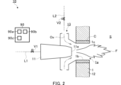
- FIG. 2 is a schematic enlarged view of part A in FIG. 1.
- the combustor 10 includes a burner 11, a refractory material 12, an oxidizer flow path 13, and a control device 90.
- the combustor 10 may further include other components.
- the burner 11 is attached to the wall of the furnace 1 outside the furnace 1.
- the burner 11 faces the combustion space S.
- the burner 11 injects a fuel containing ammonia into the combustion space S.
- the burner 11 includes a nozzle (not shown) that injects the ammonia.
- the burner 11 may further include a nozzle (not shown) that injects another fuel such as pulverized coal.
- the burner 11 may further include a nozzle (not shown) that injects an oxidizer (for example, air).
- a valve V1 may be provided in the ammonia line L1 connected to the burner 11.
- the valve V1 may be connected to the control device 90 so as to be capable of communicating with the control device 90 via wire or wirelessly, and may be controlled by the control device 90.
- the control device 90 adjusts the flow rate of ammonia supplied to the burner 11 by controlling the opening degree of the valve V1.
- the burner 11 has a generally cylindrical shape.
- the axial, radial, and circumferential directions of the burner 11 may be simply referred to as the "axial direction,” the “radial direction,” and the “circumferential direction,” unless otherwise specified.
- One end of the burner 11 in the axial direction includes an injection hole 11a and is exposed to the combustion space S.
- the injection hole 11a injects fuel into the combustion space S.
- the refractory material 12 defines at least a portion of the combustion space S.
- the refractory material 12 is part of the wall of the furnace 1 in which the burner 11 is disposed.
- the refractory material 12 blocks the passage of gas.
- the furnace 1 includes a plurality of communication holes 1a.
- the communication holes 1a penetrate the wall of the furnace 1 horizontally.
- the communication holes 1a have a cylindrical shape.
- a burner 11 is attached to each communication hole 1a. The burner 11 faces the interior of the furnace 1 through the communication hole 1a. The burner 11 injects fuel toward the space inside the communication hole 1a.
- the inner circumferential surface 1b of the communication hole 1a defines a portion of the combustion space S.
- the inner circumferential surface 1b contains a catalyst C.
- the inner circumferential surface 1b may be formed by a layer 1c of a carrier that supports the catalyst C.
- a layer 1c may be provided on the surface of a through hole formed in the wall of the furnace 1.
- the catalyst C includes a transition element (which may also be referred to as a transition metal).
- the catalyst C may include a precious metal such as Ru.
- the catalyst C may include non-precious metals such as Fe, Co, Ni, and Cu among the transition elements. Non-precious metals may exhibit high activity when combined with a specific support.
- a specific support for example, an oxide such as Al 2 O 3 or SiO 2 may be used. Also, if necessary, a support capable of suppressing sintering such as CeO 2 may be used.
- the oxidizer flow passage 13 supplies an oxidizer (e.g., air) Ox to the combustion space S.
- the oxidizer flow passage 13 is in fluid communication with the combustion space S.
- the oxidizer flow passage 13 supplies the oxidizer Ox to the combustion space S from the radial outside of the injection hole 11a.
- the oxidizer flow passage 13 is arranged radially outside the burner 11.
- the oxidizer flow passage 13 is continuous in the circumferential direction.
- the oxidizer flow passage 13 has a roughly truncated cone shape.
- the oxidizer flow passage 13 is arranged concentrically with the burner 11.
- a valve V2 may be provided in the oxidizer line L2 connected to the oxidizer flow path 13.
- the valve V2 may be connected to the control device 90 so as to be capable of communicating with the control device 90 via a wired or wireless connection, and may be controlled by the control device 90.
- the control device 90 adjusts the flow rate of the oxidizer Ox supplied to the combustion space S via the oxidizer flow path 13 by controlling the opening degree of the valve V2.
- the control device 90 controls all or part of the multiple combustors 10.
- the control device 90 may also control at least some of the other components of the boiler 100.
- the control device 90 may control the entire boiler 100.
- the boiler 100 may also be provided with a main control device (not shown), and the control device 90 may communicate with the main control device.
- the control device 90 includes components such as a processor 90a, a storage device 90b, and a connector 90c, and these components are connected to each other via a bus.
- the processor 90a includes a CPU (Central Processing Unit), etc.
- the storage device 90b includes a hard disk, a ROM in which programs, etc. are stored, and a RAM as a work area, etc.
- the control device 90 is connected to each component of the combustor 10 via the connector 90c so as to be able to communicate with each component via a wired or wireless connection.
- the control device 90 may further include other components such as a display device such as a liquid crystal display or a touch panel, and an input device such as a keyboard, a button, or a touch panel.
- the operation of the control device 90 may be realized by having the processor 90a execute a program stored in the storage device 90b.
- catalyst C can cause both reactions (1) and (2).
- the control device 90 may control the combustor 10 so that reaction (1) is the majority of the reactions in catalyst C.
- the control device 90 can increase the proportion of reaction (1) in catalyst C by controlling valve V2 to reduce the amount of oxidant Ox supplied to the combustion space S.
- the control device 90 may control valve V2 to increase the amount of oxidant Ox supplied to the combustion space S.
- Fuel containing ammonia is injected from the injection hole 11a of the burner 11 toward the combustion space S.
- oxidizer Ox is injected from the oxidizer flow path 13 toward the combustion space S.
- the mixed gas of fuel and oxidizer Ox is ignited by an ignition device (not shown), and a flame F is formed.
- the inner surface 1b of the communication hole 1a is heated by the flame F to a temperature above the temperature at which the catalyst C starts to be activated. Therefore, a part of the ammonia in the combustion space S comes into contact with the inner surface 1b and is decomposed into hydrogen and nitrogen by the catalyst C. Since the refractory material 12 blocks the passage of gas, the hydrogen and nitrogen flow radially inward from the inner surface 1b and merge with the mixed gas. Hydrogen is more combustible than ammonia. Therefore, the combustibility of the mixed gas is improved. This makes it possible to reduce unburned ammonia.
- the combustor 10 as described above includes a burner 11 that injects fuel containing ammonia into the combustion space S, and a refractory material 12 that defines at least a portion of the combustion space S.
- the refractory material 12 includes a catalyst C that blocks the passage of gas and decomposes ammonia into hydrogen and nitrogen on the inner circumferential surface 1b that defines at least a portion of the combustion space S.
- catalyst C contains a transition metal.
- the refractory material 12 is part of the wall of the furnace 1 in which the burner 11 is disposed.
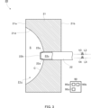
- FIG. 3 is a schematic cross-sectional view showing a combustor 20 according to the second embodiment.
- the combustor is a radiant burner 20.
- the radiant burner 20 heats the surface 21d of the burner tile 21 by burning a mixed gas containing ammonia and an oxidizer (e.g., air), and heats an object (not shown) located at a distance from the radiant burner 20 by radiant heat from the heated surface 21d.
- a mixed gas containing ammonia and an oxidizer e.g., air
- the radiant burner 20 includes a burner tile (refractory material) 21 and a burner 22.
- the radiant burner 20 may further include other components.
- the burner tile 21 is formed of a fireproof material, such as a molded product containing ceramic.
- the burner tile 21 blocks the passage of combustion gas.
- the burner tile 21 has a roughly rectangular parallelepiped shape.
- the burner tile 21 is not limited to this and may have other shapes.
- the burner tile 21 includes a front surface 21a that is arranged to face the target object, and a back surface 21b opposite the front surface 21a.
- the burner tile 21 includes a recess 21c on the front surface 21a.
- the recess 21c is formed from the front surface 21a toward the back surface 21b.
- the recess 21c is used as the combustion space S.
- the recess 21c is defined by the surface 21d. That is, the surface 21d defines the combustion space S.
- the surface 21d is a smooth spherical surface.
- the surface 21d may have other shapes, such as, for example, a cylindrical shape or a polygonal prism shape.
- the burner tile 21 may not include the recess 21c.
- surface 21d that defines the combustion space S includes a catalyst C that decomposes ammonia into hydrogen and nitrogen.
- surface 21d may be formed by a layer of a support that supports catalyst C.
- Catalyst C may be the same as that used in the first embodiment.
- the burner tile 21 including the recess 21c is also referred to as a "radiant cup.”
- the radiant burner 20 including a radiant cup is also referred to as a "radiant cup burner.”
- the burner 22 protrudes from the burner tile 21 toward the combustion space S.
- the burner 22 injects fuel containing ammonia into the combustion space S.
- the burner 22 injects a mixed gas containing ammonia and an oxidizer (e.g., air) into the combustion space S (premixing type).
- the radiant burner 20 is not limited to the premixing type, and may be a diffusion type.
- the burner 22 has a generally cylindrical or tubular shape.
- the burner 22 is located at the center of the front surface 21d.
- the burner 22 penetrates the wall of the burner tile 21 from the back surface 21b and protrudes into the recess 21c.
- the burner 22 includes a plurality of injection holes 22a.
- the injection holes 22a inject the mixed gas into the combustion space S.
- the injection holes 22a are located between the tip 22b of the burner 22 and the bottom of the recess 21c in the axial direction.
- the number of injection holes 22a may be two, three, four, five, or more.
- the multiple injection holes 22a are evenly arranged along the circumferential direction.
- the injection hole 22a opens generally in the radial direction.
- the injection hole 22a may have various shapes, such as a circular shape, an elliptical shape, or a polygonal shape.
- the inner wall of the burner 22 defines a flow path 22c for the mixed gas.
- the flow path 22c is in fluid communication with the injection hole 22a.
- the flow path 22c has a generally cylindrical shape.
- a valve V3 may be provided in the ammonia line L3 connected to the burner 22.
- the valve V3 may be connected to the control device 90 so as to be capable of communicating with the control device 90 via wire or wirelessly, and may be controlled by the control device 90.
- the control device 90 adjusts the flow rate of ammonia supplied to the burner 22 by controlling the opening degree of the valve V3.
- a valve V4 may be provided in the oxidizer line L4 connected to the burner 22.
- the valve V4 may be connected to the control device 90 so as to be capable of communicating with the control device 90 via wire or wirelessly, and may be controlled by the control device 90.
- the control device 90 adjusts the flow rate of the oxidizer supplied to the burner 22 by controlling the opening degree of the valve V4.
- control device 90 may control the radiant burner 20 so that the above reaction (1) constitutes the majority of the reaction in the catalyst C.
- a mixed gas containing ammonia and an oxidizer is injected from the injection hole 22a of the burner 22 toward the combustion space S.
- the mixed gas is injected from the injection hole 22a generally radially outward.
- the mixed gas forms a flow along the surface 21d of the recess 21c.
- the pressure in the central region of the combustion space S more specifically the pressure around the tip 22b, is lower than the pressure in the surrounding region. Therefore, the mixed gas changes its flow direction from the radially outer side to the radially inner side, and further flows toward the tip 22b along the central axis.
- the mixed gas ignites starting from the tip 22b, and is sufficiently heated and combusted before changing the flow direction.
- the high-temperature combustion gas flows toward the tip 22b.
- the surface 21d is heated by the flame.
- the catalyst C on the surface 21d promotes the combustion reaction by reducing the activation energy in the reaction (2) between the ammonia and the oxidizer. Ignition can be achieved even in a lower temperature field, and ammonia can be burned. After the oxidizer reacts, the remaining ammonia is decomposed into hydrogen and nitrogen by the catalyst C in reaction (1). As shown above, the generated hydrogen and nitrogen flow toward the tip 22b by the recirculation flow and merge with the mixed gas. Hydrogen is more combustible than ammonia. Therefore, the combustibility of the mixed gas is improved.
- the catalyst C allows ignition even in a low temperature field, realizing earlier ignition, and improving combustibility with the decomposed hydrogen. As a result, the temperature of the burner tile 21 can be increased, and the amount of radiative heat transfer can be increased.
- Such a radiant burner 20 has substantially the same effect as the combustor 10 according to the first embodiment.
- the combustor is the radiant burner 20, and the refractory material is the burner tile 21.
- the radiant burner 20 a flow of mixed gas is formed along the surface 21d of the burner tile 21. Therefore, the ammonia in the mixed gas is more likely to come into contact with the catalyst C. This allows the ammonia to be more easily decomposed into hydrogen and nitrogen. This improves the combustibility of the fuel containing ammonia. This allows the amount of unburned ammonia to be reduced.
- the radiant burner 20 is a radiant cup burner
- the burner tile 21 includes a recess 21c as at least a part of the combustion space S.
- the recess 21c is defined by the surface 21d, which is a smooth spherical surface.
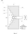
- FIG. 4 is a schematic cross-sectional view showing a radiant burner 20A according to the third embodiment.
- the combustor is also a radiant burner 20A.
- the radiant burner 20A differs from the radiant burner 20 according to the second embodiment in the shape of the surface 21d that defines the combustion space S. As for other configurations, the radiant burner 20A may be the same as the radiant burner 20.
- the surface 21d includes a plurality of steps (protrusions) 21e.
- the steps 21e protrude in the axial direction and radially inward.
- the steps 21e may be continuous in the circumferential direction.
- the steps 21e have an annular shape.
- the steps 21e may be divided in the circumferential direction.
- the surface 21d may include a plurality of grooves instead of or in addition to the steps 21e.
- Such a radiant burner 20A has substantially the same effect as the radiant burner 20 according to the second embodiment.
- the surface 21d of the burner tile 21 includes a step 21e.
- a turbulent flow of the mixed gas is generated on the surface 21d. Therefore, the mixed gas remains on the surface 21d for a longer period of time.
- the step 21e also increases the surface area of the surface 21d that contacts the combustion space S. This allows more ammonia to react on the catalyst C, and more hydrogen is generated. Therefore, the combustibility of the fuel containing ammonia is further improved.
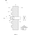
- FIG. 5 is a schematic cross-sectional view showing a combustor 20B according to the fourth embodiment.
- the combustor is also a radiant burner 20B.
- the radiant burner 20B differs from the radiant burner 20A according to the third embodiment in that the burner tile 21 does not have a cup shape. In other respects, the radiant burner 20B may be the same as the radiant burners 20 and 20A.
- the burner tile 21 has a generally flat shape and does not include a recess.
- the front surface 21a of the burner tile 21 faces the combustion space S and defines at least a portion of the combustion space S.
- the burner tile 21 also includes a plurality of protrusions 21f.
- the protrusions 21f protrude in the axial direction from the front surface 21a toward the combustion space S.
- the protrusions 21f may be continuous in the circumferential direction.
- the protrusions 21f have an annular shape.
- the protrusions 21f may be divided in the circumferential direction.
- the front surface 21a may include a plurality of grooves instead of or in addition to the protrusions 21f.
- Such a radiant burner 20B provides substantially the same effects as the radiant burner 20A according to the third embodiment.
- the present disclosure can facilitate the use of ammonia leading to reduced CO2 emissions, thereby contributing, for example, to Sustainable Development Goal (SDG) Goal 7 "Ensure access to affordable, reliable, sustainable and modern energy” and Goal 13 "Take urgent action to combat climate change and its impacts.”
- SDG Sustainable Development Goal
Landscapes
- Engineering & Computer Science (AREA)
- Chemical & Material Sciences (AREA)
- Mechanical Engineering (AREA)
- General Engineering & Computer Science (AREA)
- Combustion & Propulsion (AREA)
- Chemical Kinetics & Catalysis (AREA)
- Gas Burners (AREA)
- Combustion Of Fluid Fuel (AREA)
Abstract
Description
本開示は、燃焼器に関する。本出願は2023年6月14日に提出された日本特許出願第2023-97817号に基づく優先権の利益を主張するものであり、その内容は本出願に援用される。 This disclosure relates to a combustor. This application claims the benefit of priority to Japanese Patent Application No. 2023-97817, filed on June 14, 2023, the contents of which are incorporated herein by reference.
燃焼器では、燃焼を促進するために触媒が使用される場合がある。例えば、特許文献1は、バーナノズルに対して使用される触媒筒を開示する。このバーナノズルでは、灯油等の燃料が使用される。バーナノズルからの一次側燃焼炎は、触媒筒内に吹き込む。触媒筒は、多数の出口孔を含む。一次側燃焼炎は、触媒筒を通過する際に触媒により完全燃焼し、多数の出口孔から二次側燃焼炎として噴射される。
In combustors, catalysts are sometimes used to promote combustion. For example,
また、特許文献2は、パイプバーナに対して使用される円筒状の触媒層を開示する。触媒層は、パイプバーナを取り囲むように配置される。パイプバーナは、多数の小孔を含む。また、触媒層は、ガス透過性を有する。パイプバーナには、燃料および空気の混合ガスが供給される。混合ガスは着火され、パイプバーナの多数の小孔から火炎が形成される。また、燃焼ガスは、触媒層を通過する際に触媒燃焼される。
アンモニアは、CO2を放出しない燃料として知られている。しかしながら、アンモニアの燃焼速度は、天然ガス等の他の燃焼速度よりも遅い。したがって、上記のような燃焼器においてアンモニアを使用する場合、未燃アンモニアが問題になり得る。 Ammonia is known as a fuel that does not emit CO2 . However, the burning rate of ammonia is slower than other fuels such as natural gas. Therefore, when using ammonia in such combustors, unburned ammonia can be a problem.
本開示は、アンモニアが燃料として使用される場合に未燃アンモニアを低減することができる、燃焼器を提供することを目的とする。 The present disclosure aims to provide a combustor that can reduce unburned ammonia when ammonia is used as fuel.
本開示の一態様に係る燃焼器は、燃焼空間にアンモニアを含む燃料を噴射するバーナと、燃焼空間の少なくとも一部を画定する耐火材であって、当該耐火材は、ガスの通過を遮断し、当該耐火材は、アンモニアを水素および窒素へと分解する触媒を、燃焼空間の少なくとも一部を画定する表面に含む、耐火材と、を備える。 A combustor according to one embodiment of the present disclosure includes a burner that injects a fuel containing ammonia into a combustion space, and a refractory material that defines at least a portion of the combustion space, the refractory material blocking the passage of gas, and the refractory material including a catalyst that decomposes ammonia into hydrogen and nitrogen on a surface that defines at least a portion of the combustion space.
触媒は、遷移金属を含んでもよい。 The catalyst may contain a transition metal.
燃焼器は、ラジアントバーナであってもよく、耐火材は、バーナタイルであってもよい。 The combustor may be a radiant burner and the refractory material may be a burner tile.
ラジアントバーナは、ラジアントカップバーナであってもよく、バーナタイルは、燃焼空間の少なくとも一部としての窪みを含んでもよい。 The radiant burner may be a radiant cup burner, and the burner tile may include a recess as at least a portion of the combustion space.
窪みは、平滑な球面によって画定されてもよい。 The depression may be defined by a smooth spherical surface.
バーナタイルの触媒を含む表面は、突起および溝の少なくとも一方を含んでもよい。 The catalyst-containing surface of the burner tile may include at least one of protrusions and grooves.
耐火材は、バーナが配置される炉の壁の一部であってもよい。 The refractory material may be part of the wall of the furnace in which the burner is located.
本開示によれば、アンモニアが燃料として使用される場合に未燃アンモニアを低減することができる。 According to the present disclosure, it is possible to reduce unburned ammonia when ammonia is used as fuel.
以下に添付図面を参照しながら、本開示の実施形態について詳細に説明する。かかる実施形態に示す具体的な寸法、材料および数値等は、理解を容易とするための例示にすぎず、特に断る場合を除き、本開示を限定するものではない。なお、本明細書および図面において、実質的に同一の機能、構成を有する要素については、同一の符号を付することにより重複説明を省略し、また本開示に直接関係のない要素は図示を省略する。 Below, an embodiment of the present disclosure will be described in detail with reference to the attached drawings. Specific dimensions, materials, values, etc. shown in such embodiments are merely examples for ease of understanding, and do not limit the present disclosure unless otherwise specified. In this specification and drawings, elements having substantially the same functions and configurations are designated by the same reference numerals to avoid duplicated explanations, and elements not directly related to the present disclosure are not illustrated.
図1は、第1実施形態に係る燃焼器10を備えるボイラ100の概略的な断面図である。本実施形態では、燃焼器10は、ボイラ100に適用される。他の実施形態では、燃焼器10は、工業炉または燃焼炉等の他の燃焼設備に適用されてもよい。例えば、ボイラ100は、炉1と、煙道2と、複数の燃焼器10と、を備える。ボイラ100は、他の構成要素をさらに備えてもよい。
FIG. 1 is a schematic cross-sectional view of a
炉1は、アンモニアを含む燃料を燃焼させて、燃焼ガスを生成する。例えば、炉1は、アンモニアおよび微粉炭等の他の燃料の混合燃料を燃焼させてもよい。また、炉1は、アンモニアのみを燃焼させてもよい。また、炉1は、必要に応じて、アンモニアを含まない燃料を燃焼させてもよい。
The
炉1は、鉛直方向に延在する。炉1の下部は、燃焼空間Sを画定する。本開示において、燃焼空間とは、燃料が燃焼される空間を意味する。炉1の底部には、排出口Exが設けられる。排出口Exは、燃焼によって発生する灰分を外部に排出する。
The
煙道2は、炉1で発生した燃焼ガスを外部に案内する通路である。煙道2は、炉1の上部と接続される。例えば、煙道2は、第1煙道2aと、第2煙道2bとを含む。第1煙道2aは、炉1の上部から水平方向に延在する。第2煙道2bは、第1煙道2aの端部から下方に延在する。
The
例えば、ボイラ100は、炉1の上部に設置される不図示の過熱器を備える。過熱器は、炉1で発生した燃焼ガスと、水との間で熱交換する。これにより、水蒸気が生成される。また、例えば、ボイラ100は、再熱器、節炭器または空気予熱器等の不図示の構成要素をさらに備えてもよい。
For example, the
燃焼器10は、炉1の下部の壁に設けられる。複数の燃焼器10は、水平方向において、炉1の壁に沿って互いに離間して配置される。図1は、鉛直方向に単一列のみの燃焼器10を示すが、複数列の燃焼器10が、鉛直方向に互いに離間して配置されてもよい。
The
燃焼器10は、燃料を燃焼空間Sに噴射する。燃焼器10から噴射された燃料を着火することにより、燃焼空間Sに火炎Fが形成される。炉1には、燃焼器10から噴射された燃料を着火する不図示の着火装置が設けられる。
The
図2は、図1中のA部の概略的な拡大図である。例えば、本実施形態では、燃焼器10は、バーナ11と、耐火材12と、酸化剤流路13と、制御装置90と、を含む。燃焼器10は、他の構成要素をさらに含んでもよい。
FIG. 2 is a schematic enlarged view of part A in FIG. 1. For example, in this embodiment, the
例えば、バーナ11は、炉1の外部において、炉1の壁に取り付けられる。バーナ11は、燃焼空間Sに対向する。バーナ11は、燃焼空間Sにアンモニアを含む燃料を噴射する。バーナ11は、アンモニアを噴射する不図示のノズルを含む。また、例えば、バーナ11は、微粉炭等の他の燃料を噴射する不図示のノズルをさらに含んでもよい。また、例えば、バーナ11は、酸化剤(例えば、空気)を噴射する不図示のノズルをさらに含んでもよい。
For example, the
例えば、バーナ11に接続されるアンモニア用のラインL1には、バルブV1が設けられてもよい。バルブV1は、制御装置90と有線または無線で通信可能に接続されてもよく、制御装置90によって制御されてもよい。例えば、制御装置90は、バルブV1の開度を制御することによって、バーナ11に供給されるアンモニアの流量を調整する。
For example, a valve V1 may be provided in the ammonia line L1 connected to the
バーナ11は、概ね円筒形状を有する。本開示において、バーナ11の軸線方向、径方向および円周方向は、他に指示が無い限り、単に「軸線方向」、「径方向」および「円周方向」と称され得る。第2実施形態に係るバーナ22(後述)についても、同様である。軸線方向におけるバーナ11の一方の端部は、噴射孔11aを含み、燃焼空間Sに露出される。噴射孔11aは、燃焼空間Sに燃料を噴射する。
The
耐火材12は、燃焼空間Sの少なくとも一部を画定する。本実施形態では、耐火材12は、バーナ11が配置される炉1の壁の一部である。耐火材12は、ガスの通過を遮断する。
The
耐火材12の表面のうち、燃焼空間Sを画定する表面の少なくとも一部は、アンモニアを水素および窒素へと分解する触媒Cを含む。具体的には、本実施形態では、炉1は、複数の連通孔1aを含む。連通孔1aは、炉1の壁を水平方向に貫通する。例えば、連通孔1aは、円筒形状を有する。各連通孔1aに対して、バーナ11が取り付けられる。バーナ11は、連通孔1aを介して炉1の内部と対向する。バーナ11は、連通孔1aの内側の空間に向かって燃料を噴射する。したがって、連通孔1aの内周面1bは、燃焼空間Sの一部を画定する。
At least a portion of the surface of the
内周面1bは、触媒Cを含む。具体的には、例えば、内周面1bは、触媒Cを担持する担体の層1cによって形成されてもよい。例えば、このような層1cは、炉1の壁に形成された貫通孔の表面に設けられてもよい。
The inner
例えば、触媒Cは、遷移元素(遷移金属とも称され得る)を含む。例えば、触媒Cは、Ru等の貴金属を含んでもよい。また、例えば、触媒Cは、遷移元素のうち、Fe、Co、NiおよびCu等の非貴金属を含んでもよい。非貴金属は、特定の担体と組み合わされる場合に、高い活性を示す場合がある。担体としては、例えば、Al2O3またはSiO2等の酸化物が使用されてもよい。また、必要に応じて、CeO2等のシンタリングを抑制することができる担体が使用されてもよい。 For example, the catalyst C includes a transition element (which may also be referred to as a transition metal). For example, the catalyst C may include a precious metal such as Ru. Also, for example, the catalyst C may include non-precious metals such as Fe, Co, Ni, and Cu among the transition elements. Non-precious metals may exhibit high activity when combined with a specific support. As the support, for example, an oxide such as Al 2 O 3 or SiO 2 may be used. Also, if necessary, a support capable of suppressing sintering such as CeO 2 may be used.
酸化剤流路13は、燃焼空間Sに酸化剤(例えば、空気)Oxを供給する。酸化剤流路13は、燃焼空間Sと流体連通する。例えば、酸化剤流路13は、燃焼空間Sに対して噴射孔11aの径方向外側から酸化剤Oxを供給する。例えば、酸化剤流路13は、バーナ11の径方向外側に配置される。例えば、酸化剤流路13は、円周方向に連続する。本実施形態では、酸化剤流路13は、概ね截頭円錐台形状を有する。本実施形態では、酸化剤流路13は、バーナ11と同心に配置される。
The
例えば、酸化剤流路13に接続される酸化剤用のラインL2には、バルブV2が設けられてもよい。バルブV2は、制御装置90と有線または無線で通信可能に接続されてもよく、制御装置90によって制御されてもよい。例えば、制御装置90は、バルブV2の開度を制御することによって、酸化剤流路13を介して燃焼空間Sに供給される酸化剤Oxの流量を調整する。
For example, a valve V2 may be provided in the oxidizer line L2 connected to the
制御装置90は、複数の燃焼器10の全てまたは一部を制御する。また、制御装置90は、ボイラ100の他の構成要素の少なくとも一部を制御してもよい。例えば、制御装置90は、ボイラ100の全体を制御してもよい。また、ボイラ100は、不図示のメイン制御装置を備えてもよく、制御装置90は、メイン制御装置と通信してもよい。制御装置90は、例えば、プロセッサ90a、記憶装置90bおよびコネクタ90c等の構成要素を含み、これらの構成要素はバスを介して互いに接続される。例えば、プロセッサ90aは、CPU(Central Processing Unit)等を含む。例えば、記憶装置90bは、ハードディスク、プログラム等が格納されるROM、および、ワークエリアとしてのRAM等を含む。制御装置90は、コネクタ90cを介して燃焼器10の各構成要素と有線でまたは無線で通信可能に接続される。例えば、制御装置90は、液晶ディスプレイまたはタッチパネル等の表示装置、および、キーボード、ボタンまたはタッチパネル等の入力装置等、他の構成要素を更に含んでもよい。例えば、制御装置90の動作は、記憶装置90bに記憶されるプログラムをプロセッサ90aに実行することによって、実現されてもよい。
The
アンモニアは、触媒C上で反応し、以下の反応(1)、(2)またはそれらの組み合わせを引き起こす。
(1)NH3→1.5H2+0.5N2 ΔH=45.4(kJ/mol)
(2)2NH3+1.5O2→N2+3H2O ΔH=-382.6(kJ/mol)
Ammonia reacts on the catalyst C, causing the following reactions (1), (2), or a combination thereof:
(1) NH 3 → 1.5H 2 +0.5N 2 ΔH=45.4 (kJ/mol)
(2) 2NH 3 +1.5O 2 →N 2 +3H 2 O ΔH=-382.6 (kJ/mol)
例えば、本実施形態では、触媒Cは、反応(1)および(2)の双方を引き起こし得る。例えば、制御装置90は、反応(1)が触媒Cにおける反応の大部分となるように、燃焼器10を制御してもよい。例えば、制御装置90は、バルブV2を制御して燃焼空間Sに供給される酸化剤Oxの量を低減することによって、触媒Cにおける反応(1)の割合を増加することができる。対照的に、燃焼空間Sが燃焼のためにより多くの酸化剤Oxを必要とする場合には、制御装置90は、バルブV2を制御して燃焼空間Sに供給される酸化剤Oxの量を増加してもよい。
For example, in this embodiment, catalyst C can cause both reactions (1) and (2). For example, the
続いて、燃焼器10の動作について説明する。
Next, the operation of the
バーナ11の噴射孔11aから燃焼空間Sに向けて、アンモニアを含む燃料が噴射される。また、酸化剤流路13から燃焼空間Sに向けて、酸化剤Oxが噴射される。燃料および酸化剤Oxの混合ガスは、不図示の着火装置によって着火され、火炎Fが形成される。連通孔1aの内周面1bは、火炎Fによって、触媒Cが活性化を開始する温度以上に加熱される。したがって、燃焼空間S中のアンモニアの一部は、内周面1bと接触し、触媒Cによって水素および窒素へと分解される。耐火材12はガスの通過を遮断するため、水素および窒素は、内周面1bから径方向内側に流れ、混合ガスと合流する。水素は、アンモニアよりも燃焼しやすい。したがって、混合ガスの燃焼性が向上される。これによって、未燃のアンモニアを低減することができる。
Fuel containing ammonia is injected from the
以上のような燃焼器10は、燃焼空間Sにアンモニアを含む燃料を噴射するバーナ11と、燃焼空間Sの少なくとも一部を画定する耐火材12と、を備える。耐火材12は、ガスの通過を遮断し、かつ、アンモニアを水素および窒素へと分解する触媒Cを、燃焼空間Sの少なくとも一部を画定する内周面1bに含む。このような構成によれば、燃焼空間S中のアンモニアの一部を、触媒Cによって水素および窒素へと分解し、分解された水素を混合ガス中に戻すことができる。したがって、アンモニアを含む燃料の燃焼性が向上される。これによって、未燃のアンモニアを低減することができる。
The
また、本実施形態では、触媒Cは、遷移金属を含む。このような構成によれば、アンモニアが遷移金属と容易に相互作用し、アンモニアを効率よく分解することができる。 In addition, in this embodiment, catalyst C contains a transition metal. With this configuration, ammonia easily interacts with the transition metal, and ammonia can be decomposed efficiently.
また、本実施形態では、耐火材12は、バーナ11が配置される炉1の壁の一部である。このような構成よれば、例えば、既存の燃焼器からのわずかな設計変更によって、アンモニアを含む燃料の燃焼性を向上することができる。
In addition, in this embodiment, the
続いて、他の実施形態について説明する。 Next, other embodiments will be described.
図3は、第2実施形態に係る燃焼器20を示す概略的な断面図である。本実施形態では、燃焼器は、ラジアントバーナ20である。ラジアントバーナ20は、アンモニアおよび酸化剤(例えば、空気)を含む混合ガスの燃焼によってバーナタイル21の表面21dを加熱し、加熱された表面21dからの輻射熱によって、ラジアントバーナ20から離間する位置に配置される不図示の対象物を加熱する。
FIG. 3 is a schematic cross-sectional view showing a
例えば、ラジアントバーナ20は、バーナタイル(耐火材)21と、バーナ22と、を備える。ラジアントバーナ20は、他の構成要素をさらに備えてもよい。
For example, the
バーナタイル21は、例えば、セラミックを含む成型品等の耐火材によって形成される。バーナタイル21は、燃焼ガスの通過を遮断する。本実施形態では、バーナタイル21は、概ね直方体形状を有する。バーナタイル21はこれに限定されず、他の形状を有してもよい。バーナタイル21は、対象物に対向するように配置される前面21aと、前面21aと反対側の裏面21bと、を含む。
The
本実施形態では、バーナタイル21は、前面21aに窪み21cを含む。窪み21cは、前面21aから裏面21bに向かって形成される。窪み21cは、燃焼空間Sとして使用される。窪み21cは、表面21dによって画定される。つまり、表面21dは、燃焼空間Sを画定する。本実施形態では、表面21dは、平滑な球面である。他の実施形態では、表面21dは、例えば、円柱形状または多角柱形状等の他の形状を有してもよい。他の実施形態では、バーナタイル21は、窪み21cを含まなくてもよい。
In this embodiment, the
バーナタイル21の表面のうち、燃焼空間Sを画定する表面21dは、アンモニアを水素および窒素へと分解する触媒Cを含む。第1実施形態と同様に、例えば、表面21dは、触媒Cを担持する担体の層によって形成されてもよい。触媒Cは、第1実施形態で使用されるものと同じであってもよい。
Among the surfaces of the
本開示において、窪み21cを含むバーナタイル21は、「ラジアントカップ」とも称される。また、本開示において、ラジアントカップを含むラジアントバーナ20は、「ラジアントカップバーナ」とも称される。
In this disclosure, the
バーナ22は、バーナタイル21から燃焼空間Sに向かって突出する。バーナ22は、燃焼空間Sにアンモニアを含む燃料を噴射する。本実施形態では、バーナ22は、アンモニアおよび酸化剤(例えば、空気)を含む混合ガスを燃焼空間Sに噴射する(予混合方式)。ラジアントバーナ20は予混合方式に限定されず、拡散方式であってもよい。
The
バーナ22は、概ね円筒形状またはチューブ形状を有する。バーナ22は、表面21dの中心に位置する。バーナ22は、裏面21bからバーナタイル21の壁を貫通し、窪み21c内に突出する。
The
バーナ22は、複数の噴射孔22aを含む。噴射孔22aは、燃焼空間Sに混合ガスを噴射する。噴射孔22aは、軸線方向において、バーナ22の突端22bと、窪み21cの底部と、の間に位置する。噴射孔22aの数は、2つ、3つ、4つ、5つ、または、それより多くてもよい。例えば、複数の噴射孔22aは、円周方向に沿って均等に配置される。
The
本実施形態では、噴射孔22aは、概ね径方向に向かって開口する。噴射孔22aは、円形状、楕円形状または多角形状等、様々な形状であってもよい。
In this embodiment, the
バーナ22の内壁は、混合ガスの流路22cを画定する。流路22cは、噴射孔22aと流体連通する。流路22cは、概ね円筒形状を有する。
The inner wall of the
バーナ22に接続されるアンモニア用のラインL3には、バルブV3が設けられてもよい。バルブV3は、制御装置90と有線または無線で通信可能に接続されてもよく、制御装置90によって制御されてもよい。例えば、制御装置90は、バルブV3の開度を制御することによって、バーナ22に供給されるアンモニアの流量を調整する。
A valve V3 may be provided in the ammonia line L3 connected to the
バーナ22に接続される酸化剤用のラインL4には、バルブV4が設けられてもよい。バルブV4は、制御装置90と有線または無線で通信可能に接続されてもよく、制御装置90によって制御されてもよい。例えば、制御装置90は、バルブV4の開度を制御することによって、バーナ22に供給される酸化剤の流量を調整する。
A valve V4 may be provided in the oxidizer line L4 connected to the
第1実施形態と同様に、制御装置90は、上記の反応(1)が触媒Cにおける反応の大部分となるように、ラジアントバーナ20を制御してもよい。
Similar to the first embodiment, the
続いて、ラジアントバーナ20の動作について説明する。
Next, the operation of the
バーナ22の噴射孔22aから燃焼空間Sに向けて、アンモニアおよび酸化剤を含む混合ガスが噴射される。混合ガスは、噴射孔22aから概ね径方向外側に噴射される。混合ガスは、窪み21cの表面21dに沿う流れを形成する。燃焼空間Sの中心領域の圧力、より具体的には突端22b周りの圧力は、周囲の領域の圧力よりも低い。したがって、混合ガスは、その流れの向きを径方向外側から径方向内側に変え、さらに、中心軸に沿って突端22bに向かって流れる。混合ガスは、突端22bを起点に着火し、流れの向きを変える前に十分に加熱され、燃焼する。高温の燃焼ガスは、突端22bに向かって流れる。
A mixed gas containing ammonia and an oxidizer is injected from the
また、表面21dは、火炎によって加熱される。表面21dの触媒Cは、反応(2)のアンモニアと酸化剤との反応における活性化エネルギを低減させることで、燃焼反応を促進させる。より低い温度場でも着火させ、アンモニアを燃焼させることができる。酸化剤が反応した後、残りのアンモニアは触媒Cによって反応(1)により水素と窒素とに分解される。発生した水素および窒素は、上記に示すように、再循環流により突端22bに向かって流れ、混合ガスと合流する。水素は、アンモニアよりも燃焼しやすい。したがって、混合ガスの燃焼性が向上される。触媒Cによって低温場でも着火でき、より早期の着火を実現し、分解した水素により燃焼性を向上させる。その結果、バーナタイル21の温度を上昇させることができ、放射伝熱量を高めることができる。
Furthermore, the
このようなラジアントバーナ20は、第1実施形態に係る燃焼器10と概ね同様な効果を奏する。また、本実施形態では、燃焼器は、ラジアントバーナ20であり、耐火材は、バーナタイル21である。ラジアントバーナ20では、バーナタイル21の表面21dに沿う混合ガスの流れが形成される。したがって、混合ガス中のアンモニアは触媒Cと接し易い。このため、アンモニアを水素および窒素へとより分解することができる。したがって、アンモニアを含む燃料の燃焼性が向上される。これによって、未燃のアンモニアを低減することができる。
Such a
また、本実施形態では、ラジアントバーナ20は、ラジアントカップバーナであり、バーナタイル21は、燃焼空間Sの少なくとも一部としての窪み21cを含む。このような構成によれば、混合ガスは、窪み21c内に長く留まることができる。これによって、より多くのアンモニアが、触媒C上で反応することができ、より多くの水素が発生する。したがって、アンモニアを含む燃料の燃焼性がより向上される。
In addition, in this embodiment, the
また、本実施形態では、窪み21cは、平滑な球面である表面21dによって画定される。このような構成によれば、バーナタイル前で循環流が形成され、滞留時間を長くし効率よく燃料ガスを燃焼できる。
In addition, in this embodiment, the
図4は、第3実施形態に係るラジアントバーナ20Aを示す概略的な断面図である。本実施形態においても、燃焼器は、ラジアントバーナ20Aである。ラジアントバーナ20Aは、燃焼空間Sを画定する表面21dの形状において、第2実施形態に係るラジアントバーナ20と異なる。他の構成については、ラジアントバーナ20Aは、ラジアントバーナ20と同じであってもよい。
FIG. 4 is a schematic cross-sectional view showing a
本実施形態では、表面21dは、複数の段部(突起)21eを含む。段部21eは、軸線方向にかつ径方向内側に突出する。例えば、段部21eは、円周方向に連続であってもよい。この場合、段部21eは、円環形状を有する。他の実施形態では、段部21eは、円周方向に分割されていてもよい。また、他の実施形態では、表面21dは、段部21eに代えてまたは加えて、複数の溝を含んでもよい。
In this embodiment, the
このようなラジアントバーナ20Aは、第2実施形態に係るラジアントバーナ20と概ね同様な効果を奏する。また、本実施形態では、バーナタイル21の表面21dは、段部21eを含む。このような構成によれば、表面21d上に、混合ガスの乱流が発生される。したがって、混合ガスは、表面21d上により長く留まる。また、段部21eによって、表面21dにおいて燃焼空間Sと接する表面積が増大する。これによって、より多くのアンモニアが、触媒C上で反応することができ、より多くの水素が発生する。したがって、アンモニアを含む燃料の燃焼性がより向上される。
Such a
図5は、第4実施形態に係る燃焼器20Bを示す概略的な断面図である。本実施形態においても、燃焼器は、ラジアントバーナ20Bである。ラジアントバーナ20Bは、バーナタイル21がカップ形状を有さない点において、第3実施形態に係るラジアントバーナ20Aと異なる。他の構成については、ラジアントバーナ20Bは、ラジアントバーナ20,20Aと同じであってもよい。
FIG. 5 is a schematic cross-sectional view showing a
本実施形態では、バーナタイル21は、概ねフラット形状を有し、窪みを含まない。本実施形態では、バーナタイル21の前面21aが燃焼空間Sに面し、燃焼空間Sの少なくとも一部を画定する。また、バーナタイル21は、複数の突起21fを含む。突起21fは、前面21aから燃焼空間Sに向かって軸線方向に突出する。例えば、突起21fは、円周方向に連続であってもよい。この場合、突起21fは、円環形状を有する。他の実施形態では、突起21fは、円周方向に分割されてもよい。また、他の実施形態では、前面21aは、突起21fに代えてまたは加えて、複数の溝を含んでもよい。
In this embodiment, the
このようなラジアントバーナ20Bは、第3実施形態に係るラジアントバーナ20Aと概ね同様な効果を奏する。
Such a
以上、添付図面を参照しながら実施形態について説明したが、本開示は上記実施形態に限定されない。当業者であれば、特許請求の範囲に記載された範疇において、各種の変更例または修正例に想到し得ることは明らかであり、それらについても当然に本開示の技術的範囲に属するものと了解される。 Although the embodiments have been described above with reference to the attached drawings, the present disclosure is not limited to the above-described embodiments. It is clear that a person skilled in the art can conceive of various modified or revised examples within the scope of the claims, and it is understood that these also naturally fall within the technical scope of the present disclosure.
本開示は、CO2放出の削減につながるアンモニアの使用を促進することができるので、例えば、持続可能な開発目標(SDGs)の目標7「手ごろで信頼でき、持続可能かつ近代的なエネルギへのアクセスを確保する」および目標13「気候変動とその影響に立ち向かうため、緊急対策を取る」に貢献することができる。
The present disclosure can facilitate the use of ammonia leading to reduced CO2 emissions, thereby contributing, for example, to Sustainable Development Goal (SDG) Goal 7 "Ensure access to affordable, reliable, sustainable and modern energy" and
1 炉
1b 内周面(燃焼空間の少なくとも一部を画定する表面)
10 燃焼器
11 バーナ
12 耐火材
20 ラジアントバーナ(燃焼器)
20A ラジアントバーナ(燃焼器)
20B ラジアントバーナ(燃焼器)
21 バーナタイル(耐火材)
21a 前面(燃焼空間の少なくとも一部を画定する表面)
21c 窪み
21d 表面(燃焼空間の少なくとも一部を画定する表面)
21e 段部(突起)
21f 突起
22 バーナ
C 触媒
S 燃焼空間
1
10 Combustor 11
20A Radiant burner (combustor)
20B Radiant burner (combustor)
21 Burner tile (fireproof material)
21a front surface (surface defining at least a portion of the combustion space)
21e Step (protrusion)
Claims (8)
前記燃焼空間の少なくとも一部を画定する耐火材であって、
当該耐火材は、ガスの通過を遮断し、
当該耐火材は、アンモニアを水素および窒素へと分解する触媒を、前記燃焼空間の前記少なくとも一部を画定する表面に含む、
耐火材と、
を備える、燃焼器。 a burner that injects fuel containing ammonia into a combustion space;
A refractory material defining at least a portion of the combustion space,
The fireproof material blocks the passage of gas,
the refractory material includes a catalyst on a surface defining at least a portion of the combustion space that decomposes ammonia into hydrogen and nitrogen;
A fireproof material;
A combustor comprising:
前記耐火材は、バーナタイルである、
請求項1または2に記載の燃焼器。 The combustor is a radiant burner,
The refractory material is a burner tile.
The combustor according to claim 1 or 2.
前記バーナタイルは、前記燃焼空間の前記少なくとも一部としての窪みを含む、
請求項3に記載の燃焼器。 The radiant burner is a radiant cup burner,
The burner tile includes a recess as at least a portion of the combustion space.
The combustor of claim 3 .
請求項4に記載の燃焼器。 The recess is defined by a smooth spherical surface.
The combustor of claim 4 .
請求項3に記載の燃焼器。 the catalyst-containing surface of the burner tile includes at least one of protrusions and grooves;
The combustor of claim 3 .
請求項4に記載の燃焼器。 the catalyst-containing surface of the burner tile includes at least one of protrusions and grooves;
The combustor of claim 4 .
Priority Applications (3)
| Application Number | Priority Date | Filing Date | Title |
|---|---|---|---|
| KR1020257024875A KR20250124245A (en) | 2023-06-14 | 2024-03-25 | burner |
| CN202480006751.6A CN120569594A (en) | 2023-06-14 | 2024-03-25 | Burner with a burner body |
| JP2025527471A JP7835350B2 (en) | 2023-06-14 | 2024-03-25 | Combustor |
Applications Claiming Priority (2)
| Application Number | Priority Date | Filing Date | Title |
|---|---|---|---|
| JP2023-097817 | 2023-06-14 | ||
| JP2023097817 | 2023-06-14 |
Publications (1)
| Publication Number | Publication Date |
|---|---|
| WO2024257430A1 true WO2024257430A1 (en) | 2024-12-19 |
Family
ID=93851811
Family Applications (1)
| Application Number | Title | Priority Date | Filing Date |
|---|---|---|---|
| PCT/JP2024/011669 Ceased WO2024257430A1 (en) | 2023-06-14 | 2024-03-25 | Combustor |
Country Status (4)
| Country | Link |
|---|---|
| JP (1) | JP7835350B2 (en) |
| KR (1) | KR20250124245A (en) |
| CN (1) | CN120569594A (en) |
| WO (1) | WO2024257430A1 (en) |
Citations (9)
| Publication number | Priority date | Publication date | Assignee | Title |
|---|---|---|---|---|
| JPS61256110A (en) * | 1985-05-04 | 1986-11-13 | Shoei Seisakusho:Kk | Radiant cup burner tile |
| US20070105060A1 (en) * | 2005-11-04 | 2007-05-10 | Nova Chemicals (International) S.A. | Industrial radiant heater |
| JP2013257125A (en) * | 2012-06-13 | 2013-12-26 | Takeshi Hatanaka | Next-generation carbon-free power generation plant, next-generation carbon-free power generation method, and urea water used for the next-generation carbon-free power generation plant and the next-generation carbon-free power generation method |
| JP2018096616A (en) * | 2016-12-13 | 2018-06-21 | 三菱日立パワーシステムズ株式会社 | Caloric power-generating plant, boiler and method for improving boiler |
| WO2020054748A1 (en) * | 2018-09-11 | 2020-03-19 | 株式会社Ihi | Combustion apparatus and boiler |
| JP2022091407A (en) * | 2020-12-09 | 2022-06-21 | 川崎重工業株式会社 | Fuel burning system |
| JP2022154831A (en) * | 2021-03-30 | 2022-10-13 | 東京瓦斯株式会社 | Burner |
| CN115342334A (en) * | 2022-07-04 | 2022-11-15 | 国家电投集团碳资产管理有限公司 | A liquid ammonia and coal-fired complementary power generation system and method |
| CN116557858A (en) * | 2023-03-17 | 2023-08-08 | 合肥综合性国家科学中心能源研究院(安徽省能源实验室) | A kind of ammonia burner based on plasma cracking, thermal cracking and plasma combustion and its operation method |
Family Cites Families (3)
| Publication number | Priority date | Publication date | Assignee | Title |
|---|---|---|---|---|
| JPS5579925A (en) * | 1978-12-14 | 1980-06-16 | Matsushita Electric Ind Co Ltd | Burning apparatus |
| JP2882605B2 (en) | 1987-08-27 | 1999-04-12 | テキサス インスツルメンツ インコーポレイテッド | Continuous growth method of strained layer superlattice structure |
| JPH11281006A (en) | 1998-03-26 | 1999-10-15 | Nagano Kensetsu Kk | Catalyst cylinder for combustion inside furnace |
-
2024
- 2024-03-25 WO PCT/JP2024/011669 patent/WO2024257430A1/en not_active Ceased
- 2024-03-25 JP JP2025527471A patent/JP7835350B2/en active Active
- 2024-03-25 KR KR1020257024875A patent/KR20250124245A/en active Pending
- 2024-03-25 CN CN202480006751.6A patent/CN120569594A/en active Pending
Patent Citations (9)
| Publication number | Priority date | Publication date | Assignee | Title |
|---|---|---|---|---|
| JPS61256110A (en) * | 1985-05-04 | 1986-11-13 | Shoei Seisakusho:Kk | Radiant cup burner tile |
| US20070105060A1 (en) * | 2005-11-04 | 2007-05-10 | Nova Chemicals (International) S.A. | Industrial radiant heater |
| JP2013257125A (en) * | 2012-06-13 | 2013-12-26 | Takeshi Hatanaka | Next-generation carbon-free power generation plant, next-generation carbon-free power generation method, and urea water used for the next-generation carbon-free power generation plant and the next-generation carbon-free power generation method |
| JP2018096616A (en) * | 2016-12-13 | 2018-06-21 | 三菱日立パワーシステムズ株式会社 | Caloric power-generating plant, boiler and method for improving boiler |
| WO2020054748A1 (en) * | 2018-09-11 | 2020-03-19 | 株式会社Ihi | Combustion apparatus and boiler |
| JP2022091407A (en) * | 2020-12-09 | 2022-06-21 | 川崎重工業株式会社 | Fuel burning system |
| JP2022154831A (en) * | 2021-03-30 | 2022-10-13 | 東京瓦斯株式会社 | Burner |
| CN115342334A (en) * | 2022-07-04 | 2022-11-15 | 国家电投集团碳资产管理有限公司 | A liquid ammonia and coal-fired complementary power generation system and method |
| CN116557858A (en) * | 2023-03-17 | 2023-08-08 | 合肥综合性国家科学中心能源研究院(安徽省能源实验室) | A kind of ammonia burner based on plasma cracking, thermal cracking and plasma combustion and its operation method |
Also Published As
| Publication number | Publication date |
|---|---|
| JPWO2024257430A1 (en) | 2024-12-19 |
| JP7835350B2 (en) | 2026-03-25 |
| CN120569594A (en) | 2025-08-29 |
| KR20250124245A (en) | 2025-08-19 |
Similar Documents
| Publication | Publication Date | Title |
|---|---|---|
| CN104884866B (en) | Perforated flame holder and burner including perforated flame holder | |
| US7363756B2 (en) | Method for combustion of a fuel | |
| JP4670035B2 (en) | Gas turbine combustor | |
| JP2022154831A (en) | Burner | |
| JP2006118854A (en) | Method and system for rich-lean catalytic combustion | |
| EP2764294B1 (en) | Aphlogistic burner | |
| AU2022310752B2 (en) | Reforming device | |
| KR20240134167A (en) | Flare stack and system having flare stack | |
| JP7835350B2 (en) | Combustor | |
| JP3873119B2 (en) | In-cylinder swirl combustor | |
| WO2025094456A1 (en) | Furnace | |
| JP2025005757A (en) | Combustor and combustion method | |
| JP4068041B2 (en) | Low NOx burner | |
| JP5009593B2 (en) | Combustion device | |
| JP5135123B2 (en) | Combustion equipment | |
| WO2025069633A1 (en) | Radiant burner | |
| JP7494358B1 (en) | Dual-fuel burners and boilers | |
| JP7819787B2 (en) | radiant burner | |
| JPH07110101A (en) | Monotube boiler | |
| KR20260046471A (en) | Burner, operating method, and combustion device | |
| WO2024257438A1 (en) | Fuel preheater | |
| KR20260061545A (en) | paddle | |
| WO2023007929A1 (en) | Combustor | |
| CN121693647A (en) | Ammonia co-firing burner and ammonia co-firing system using the ammonia co-firing burner are manufactured according to the manufacturing method. | |
| JP2023067336A (en) | Burner |
Legal Events
| Date | Code | Title | Description |
|---|---|---|---|
| 121 | Ep: the epo has been informed by wipo that ep was designated in this application |
Ref document number: 24823053 Country of ref document: EP Kind code of ref document: A1 |
|
| WWE | Wipo information: entry into national phase |
Ref document number: 2025527471 Country of ref document: JP |
|
| WWE | Wipo information: entry into national phase |
Ref document number: 202480006751.6 Country of ref document: CN |
|
| ENP | Entry into the national phase |
Ref document number: 1020257024875 Country of ref document: KR Free format text: ST27 STATUS EVENT CODE: A-0-1-A10-A15-NAP-PA0105 (AS PROVIDED BY THE NATIONAL OFFICE) |
|
| WWE | Wipo information: entry into national phase |
Ref document number: 1020257024875 Country of ref document: KR |
|
| WWP | Wipo information: published in national office |
Ref document number: 1020257024875 Country of ref document: KR |
|
| WWP | Wipo information: published in national office |
Ref document number: 202480006751.6 Country of ref document: CN |
|
| NENP | Non-entry into the national phase |
Ref country code: DE |