WO2024257431A1 - Roue - Google Patents
Roue Download PDFInfo
- Publication number
- WO2024257431A1 WO2024257431A1 PCT/JP2024/011837 JP2024011837W WO2024257431A1 WO 2024257431 A1 WO2024257431 A1 WO 2024257431A1 JP 2024011837 W JP2024011837 W JP 2024011837W WO 2024257431 A1 WO2024257431 A1 WO 2024257431A1
- Authority
- WO
- WIPO (PCT)
- Prior art keywords
- wheel
- barrel
- barrel shaft
- pair
- region
- Prior art date
- Legal status (The legal status is an assumption and is not a legal conclusion. Google has not performed a legal analysis and makes no representation as to the accuracy of the status listed.)
- Ceased
Links
Images


Classifications
-
- B—PERFORMING OPERATIONS; TRANSPORTING
- B60—VEHICLES IN GENERAL
- B60B—VEHICLE WHEELS; CASTORS; AXLES FOR WHEELS OR CASTORS; INCREASING WHEEL ADHESION
- B60B19/00—Wheels not otherwise provided for or having characteristics specified in one of the subgroups of this group
Definitions
- a wheel having multiple barrel members is disclosed (see, for example, Patent Document 1 or Patent Document 2).
- Wheels with multiple barrel components are required to operate stably when incorporated into a moving body as a Mecanum wheel.
- multiple barrel components are incorporated into a wheel, there are cases where it is necessary to replace some of the barrel components. In such cases, good assembly properties are required to enable easy attachment and detachment of the barrel components.
- one of the objectives is to provide a wheel that can ensure stable operation while also allowing for easy assembly.
- a wheel according to the present disclosure includes a plurality of barrel members and a wheel body to which the plurality of barrel members are attached on the outer periphery.
- the barrel members include an outer skin portion having an outer periphery formed of a curved surface and a diameter gradually increasing from both ends of the barrel member in the longitudinal direction toward the center, a barrel shaft extending in the longitudinal direction and arranged to penetrate the outer skin portion in the longitudinal direction and having threads at both ends, a bearing portion for receiving a load applied to the barrel shaft, a pair of receivers each having a through hole into which the barrel shaft is inserted, and a pair of nuts each having a thread groove and attached to the threads of the barrel shaft on the outside of the pair of receivers.
- the wheel body includes a pair of plate portions each rotatably supporting the barrel shaft, and a main body portion holding the pair of plate portions at a distance in the direction of the rotation axis of the wheel.
- Each of the pair of plate portions is provided with a groove portion that is open to the outer diameter side and receives the barrel shaft.
- the above wheels ensure stable operation and facilitate easy assembly.
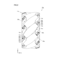
- FIG. 1 is a schematic perspective view showing a wheel according to a first embodiment of the present disclosure.
- FIG. 2 is a schematic side view of the wheel shown in FIG.
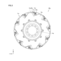
- FIG. 3 is a schematic front view of the wheel shown in FIG.
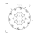
- FIG. 4 is a schematic rear view of the wheel shown in FIG.
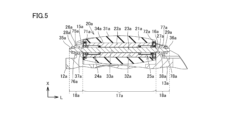
- FIG. 5 is a schematic cross-sectional view showing an enlarged portion of a wheel including one barrel member.
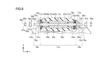
- FIG. 6 is a schematic cross-sectional view showing a state in which a nut and a receiving tool, which will be described later, have been removed from FIG.
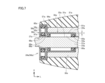
- FIG. 7 is an enlarged view of the area indicated by VII in FIG.
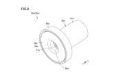
- FIG. 8 is a schematic perspective view showing the appearance of the bearing portion.
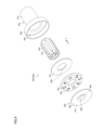
- FIG. 9 is an exploded perspective view of the bearing portion shown in FIG.
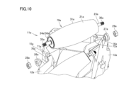
- FIG. 10 is a schematic perspective view showing a portion of the wheel during assembly.
- FIG. 11 is a diagram showing a state in which the structure is assembled into the plate portion.
- the wheel of the present disclosure includes a plurality of barrel members and a wheel body to which the plurality of barrel members are attached on the outer periphery.
- the barrel members include an outer shell portion having an outer periphery with a curved surface and a diameter gradually increasing from both ends of the barrel member in the longitudinal direction toward the center, a barrel shaft extending in the longitudinal direction and arranged to penetrate the outer shell portion in the longitudinal direction and having threads at both ends, a bearing portion for receiving a load applied to the barrel shaft, a pair of receivers each having a through hole into which the barrel shaft is inserted, and a pair of nuts each having a thread groove and attached to the threads of the barrel shaft on the outside of the pair of receivers.
- the wheel body includes a pair of plate portions each rotatably supporting the barrel shaft, and a main body portion holding the pair of plate portions at an interval in the direction of the rotation axis of the wheel.
- Each of the pair of plate portions is provided with a groove portion that is open to the outer diameter side and receives the barrel shaft.
- the barrel shaft with the outer shell attached can be supported by the pair of plate parts using the groove that receives the barrel shaft.
- the groove has a shape that is open to the outer diameter side of the wheel, so the barrel shaft can be easily assembled from the outer diameter side of the wheel.
- the barrel shaft attached to the pair of plate parts can be securely fixed by attaching a receiving tool and tightening it with a nut.
- a load acts on the barrel member in the inner diameter direction, and no load is applied in the outer diameter direction. Therefore, even if a groove is provided on the plate part, there is no problem in terms of strength.
- the barrel shaft can be securely prevented from coming off in the outer diameter direction by the holding tool and the nut.
- the barrel shaft can be securely prevented from falling off while ensuring stable operation of the wheel.
- the receiving tool and the nut can be removed to easily remove the barrel shaft from the outer diameter side of the wheel.
- the receiver may include a small diameter region including one end in the longitudinal direction, and a large diameter region including the other end in the longitudinal direction and having an outer diameter larger than that of the small diameter region.
- the plate portion may be provided with a fitting recess that is recessed in the longitudinal direction from the outer surface and includes a groove portion.
- the small diameter region may be fitted into the fitting recess.
- the wall surface that constitutes the groove may be shaped to extend straight toward the outer diameter side of the wheel. By doing so, the barrel shaft with the outer skin etc. set thereon can be more smoothly inserted into the groove from the outer diameter side of the wheel. This can further improve the ease of assembly.
- the barrel shaft may include a first region sandwiched between a pair of plate portions in the longitudinal direction, and a second region located on both ends of the first region.
- the outer diameter of the first region may be larger than the outer diameter of the second region.
- the groove may receive the barrel shaft in the second region. In this way, it becomes easier to hook the first region onto the pair of plate portions in the longitudinal direction of the barrel shaft, making it easier to restrict longitudinal movement of the barrel shaft. Therefore, more stable wheel operation can be ensured.
- the bearing portion may receive radial loads and thrust loads. In this way, the radial loads and thrust loads applied to the barrel shaft can be properly received by the bearing portion. This ensures more stable wheel operation.
- the bearing portion may be a shell composite roller bearing including a shell outer ring.
- the bearing that receives the radial load and the bearing that receives the thrust load are integrated, which makes it possible to efficiently attach the bearing portion to the barrel shaft and also reduces the number of parts. This can further improve productivity.
- the shell composite roller bearing may include a ring member that also serves as one of the raceways that receives the load in the thrust direction. In this way, the thrust load can be properly received by the ring member. This ensures more stable operation of the wheel.
- the shell composite roller bearing may include a shell outer ring that constitutes an outer ring that receives a radial load.
- the shell outer ring may include a portion located on the outer periphery of the roller that receives a thrust load. In this way, the shell outer ring can integrate the parts located on the outer diameter side of the bearing portion, improving assembly ease. This can further improve productivity.
- the thickness of the shell outer ring may be 0.2 mm or more and 3.2 mm or less. This allows the shell outer ring to be efficiently manufactured by drawing or the like while maintaining the rigidity required for a member constituting a wheel. This allows for improved productivity.
- Fig. 1 is a schematic perspective view showing a wheel in the first embodiment of the present disclosure.
- Fig. 2 is a schematic side view of the wheel shown in Fig. 1.
- Fig. 3 is a schematic front view of the wheel shown in Fig. 1.
- Fig. 4 is a schematic rear view of the wheel shown in Fig. 1.
- the direction indicated by arrow Z is the rotation axis direction of the wheel, and the directions indicated by arrows X and Y are radial directions.
- the direction indicated by arrow X and the direction indicated by arrow Y are perpendicular to each other.
- the wheel 10a of the present disclosure is also called a Mecanum wheel, and is used, for example, as a wheel for a moving object.
- the moving object can be moved in all directions without using a handle.
- Four wheels 10a are attached to the moving object, for example, front, back, left and right.
- the size of the wheel 10a for example the length in the X direction in Figure 2, is 150 mm.
- the wheel 10a includes a plurality of barrel members 20a, ten in this embodiment, and a wheel body 11a to which the plurality of barrel members 20a are attached on the outer periphery.
- the wheel body 11a includes a pair of plate portions 12a, 13a and a main body portion 14a.
- the plate portions 12a, 13a are each disk-shaped and have a through hole in the radial center.
- the plate portion 12a is provided with a support portion 15a that supports the barrel shaft 23a of the barrel member 20a described later.
- the plate portion 13a is provided with a support portion 16a that supports the barrel shaft.
- the pair of plate portions 12a, 13a each rotatably support the barrel shaft.
- the main body portion 14a is cylindrical and has a plurality of mounting holes.
- the main body portion 14a holds the pair of plate portions 12a, 13a at an interval in the rotation axis direction (Z direction) of the wheel 10a.
- the main body portion 14a is connected to a driving source such as a motor (not shown).
- the wheel 10a rotates at a controlled speed and in a controlled direction based on the power transmitted from a motor or the like.
- Figure 5 is a schematic cross-sectional view showing an enlarged portion of a wheel 10a including one barrel member 20a.
- Figure 5 corresponds to a cross-sectional view taken along the central axis of rotation of the barrel member 20a.
- Figure 6 is a schematic cross-sectional view showing the state in Figure 5 after removing receivers 26a, 27a and nuts 28a, 29a, which will be described later.
- Figure 7 is an enlarged view of the area indicated by VII in Figure 6.
- Figure 7 is a schematic cross-sectional view showing an enlarged bearing portion, which will be described later, in Figure 6.
- the longitudinal direction of the barrel member 20a is shown by the direction indicated by arrow L.
- the L direction is inclined at 45 degrees with respect to the Z direction.
- the barrel member 20a includes an outer shell 21a, a core 22a, a barrel shaft 23a, a pair of bearings 24a, 25a, a pair of receivers 26a, 27a, and a pair of nuts 28a, 29a.
- the outer shell 21a has an outer peripheral surface 31a that is curved.
- the diameter of the outer peripheral surface 31a gradually increases from both ends of the longitudinal direction of the barrel member 20a toward the center. That is, the diameter of the barrel member 20a is the largest at the center of the longitudinal direction of the outer shell 21a of the barrel member 20a, and the diameter D2 at both ends of the longitudinal direction of the outer shell 21a of the barrel member 20a is the smallest (see FIG. 6 in particular). In the cross-sections shown in FIGS.
- the outer shell 21a is a barrel-shaped member.
- the outer skin 21a has a hole 32a that penetrates in the longitudinal direction.
- the core 22a is disposed in the hole 32a.
- the outer skin 21a is attached so as to cover the core 22a.
- the longitudinal length of the outer skin 21a is longer than the longitudinal length of the core 22a.
- the outer skin 21a has elasticity. Rubber or resin is selected as the material of the outer skin 21a. In this embodiment, the material of the outer skin 21a is urethane rubber. When resin is used as the material of the outer skin 21a, for example, POM (Poly oxymethylene) resin, PA (Poly amide) resin, or PEEK (Poly Ether Ether Ketone) resin is used.
- the core 22a is composed of a member having rigidity. For example, aluminum-based metal or steel is used as the material of the core 22a, and specifically, A5052 or A6063 is used.
- the barrel shaft 23a is a round bar shaped solid cylinder extending in the longitudinal direction.
- the barrel shaft 23a is arranged so as to penetrate the outer skin 21a in the longitudinal direction.
- the barrel shaft 23a is arranged in a hole 33a that penetrates the core 22a in the longitudinal direction and is provided in the center of the core 22a.
- the outer peripheral surface 34a of the barrel shaft 23a contacts the inner wall surface of the hole 33a. Both ends of the barrel shaft 23a protrude from both end faces of the outer skin 21a and the core 22a.
- Threads 35a, 36a are provided on both ends of the barrel shaft 23a. The areas where the threads 35a, 36a are provided are exposed from both end faces of the core 22a.
- the barrel shaft 23a includes a first region 17a sandwiched between a pair of plate portions 12a, 13a in the longitudinal direction, and a second region 18a located at both ends of the first region 17a.
- the second regions 18a are provided in pairs spaced apart in the longitudinal direction.
- the boundaries between the first region 17a and the pair of second regions 18a are shown by dashed lines in Figures 5 and 6.
- the outer diameter of the first region 17a is larger than the outer diameter of the second regions 18a. This configuration gives the barrel shaft 23a a so-called stepped configuration.
- the outer circumferential surface 34a of the barrel shaft 23a is provided with a pair of circumferential grooves 37a, 38a recessed toward the inner diameter side.
- the circumferential grooves 37a, 38a are formed with a gap in the longitudinal direction.
- the circumferential grooves 37a, 38a are provided in the boundary region between the first region 17a and the second region 18a in the longitudinal direction.
- the circumferential grooves 37a, 38a are used as escape grooves in machining when the barrel shaft 23a is configured with a step.
- the circumferential grooves 37a, 38a are provided toward the center in the longitudinal direction relative to the threads 35a, 36a. In this embodiment, the circumferential grooves 37a, 38a are provided so as to be aligned with both end faces of the outer skin portion 21a in the longitudinal direction.
- receiver 26a and nut 28a will be described.
- the configuration of receiver 27a is similar to that of receiver 26a, so its description will be omitted.
- the configuration of nut 29a is similar to that of nut 28a, so its description will be omitted.
- the receiver 26a is a member also called a collar, and is made of aluminum.
- the receiver 26a may be made of steel.
- the receiver 26a includes a small diameter region 41a including one end in the longitudinal direction, and a large diameter region 42a including the other end in the longitudinal direction and having a larger outer diameter than the small diameter region 41a.
- the receiver 26a is a hollow cylindrical member with a flange portion formed on one end side that extends to the outer diameter side.
- the receiver 26a is provided with a through hole 43a that penetrates in the axial direction.
- the barrel shaft 23a is inserted into this through hole 43a.
- the receiver 26a is attached to the barrel shaft 23a so that the small diameter region 41a is on the inside, i.e., the center side of the barrel shaft 23a.
- the barrel shaft 23a is inserted into the through hole 43a so that the large diameter region 42a faces the one end in the longitudinal direction where the thread 35a is formed, and the receiver 26a is attached to the barrel shaft 23a.
- the barrel shaft 23a is inserted into the through hole 43a so that the large diameter region 42a faces the other end in the longitudinal direction where the thread 36a is formed, and the receiver 27a is attached to the barrel shaft 23a.
- the nut 28a has a thread groove 47a on the inner wall surface that defines the hole 46a.
- the outer shape of the head of the nut 28a is hexagonal when viewed in the longitudinal direction.
- the nut 28a is attached by rotating the nut 28a outside the receiver 27a and tightening the thread groove 47a onto the thread 35a provided on the end of the barrel shaft 23a.
- the nut 29a is attached by rotating the nut 29a outside the receiver 27a and tightening the thread groove 47a onto the thread 36a provided on the end of the barrel shaft 23a.
- bearing portion 24a The configuration of bearing portion 25a is similar to that of bearing portion 24a, so we will not repeat the explanation.
- FIG. 8 is a schematic perspective view showing the appearance of bearing portion 24a.
- FIG. 9 is an exploded perspective view of bearing portion 24a shown in FIG. 8.
- bearing portion 24a receives radial loads and thrust loads.
- Bearing portion 24a is a shell composite roller bearing 50a including a shell outer ring 55a, which will be described later.
- the shell composite roller bearing 50a includes a plurality of first rollers 51a, a plurality of second rollers 52a, a first retainer 53a that holds the plurality of first rollers 51a, a second retainer 54a that holds the plurality of second rollers 52a, a shell outer ring 55a, a raceway ring 56a, and a ring member 57a.
- the first rollers 51a receive a radial load.
- the second rollers 52a receive a thrust load.
- the raceway ring 56a and the ring member 57a are raceways that come into contact with the rolling surfaces of the second rollers 52a and receive a thrust load.
- the shell outer ring 55a includes a first cylindrical portion 61a, a second cylindrical portion 62a, a bottom portion 63a, and a flange portion 64a.
- a hole 65a is provided in the bottom portion 63a, and the barrel shaft 23a is inserted into this hole 65a.
- the first cylindrical portion 61a and the second cylindrical portion 62a are each hollow cylindrical.
- the outer diameter of the second cylindrical portion 62a is larger than the outer diameter of the first cylindrical portion 61a.
- a plurality of first rollers 51a that receive a radial load are arranged on the inner diameter side of the first cylindrical portion 61a.
- the first rollers 51a roll on the outer circumferential surface 34a of the barrel shaft 23a and the inner circumferential surface of the first cylindrical portion 61a as the orbital surface.
- the flange portion 64a is a disk shape that extends from one axial end of the first cylindrical portion 61a to the outer diameter side.
- the flange 64a is provided to connect one axial end of the first cylindrical portion 61a to the other axial end of the second cylindrical portion 62a.
- a plurality of second rollers 52a that receive a thrust load are arranged on the inner diameter side of the second cylindrical portion 62a.
- the thickness T of the shell outer ring 55a is 0.2 mm or more and 3.2 mm or less. In this embodiment, the thickness T of the shell outer ring 55a is 0.5 mm.
- the shell outer ring 55a is constructed as a single piece. The shell outer ring 55a is manufactured, for example, by drawing a steel plate.
- the raceway 56a includes a disk-shaped disk portion 67a with a hole 66a in the center, and a flange portion 68a extending in the thickness direction from the edge of the hole 66a.
- the raceway 56a is attached by inserting the barrel shaft 23a into the hole 66a.
- the ring member 57a is disk-shaped and has a hole 69a in the radial center that penetrates in the thickness direction.
- the ring member 57a is placed in the shell composite roller bearing 50a by inserting the barrel shaft 23a into the hole 66a so that it comes into contact with the flange portion 64a.
- the second roller 52a rolls on one surface of the raceway 56a and the other surface of the ring member 57a as the raceway surface.
- the outer end face of the shell composite roller bearing 50a which is the bearing portion 24a, in this case the end face 58a of the raceway ring 56a opposite the raceway surface, is aligned with the position where the circumferential groove 37a is provided on the outer circumferential surface 34a of the barrel shaft 23a in the longitudinal direction.
- the bearing portion 25a When adjusting the longitudinal gap based on manufacturing errors, etc., a spring washer or a simple washer may be placed so as to come into contact with the end face 58a.
- the pair of plate portions 12a, 13a are each provided with groove portions 71a, 72a that receive the barrel shaft 23a.
- the groove portions 71a, 72a each receive the barrel shaft 23a in the second region 18a.
- the groove portion 71a is provided in a support portion 15a provided on the outer periphery of the plate portion 12a.
- the groove portion 72a is provided in a support portion 16a provided on the outer periphery of the plate portion 13a.
- the groove portions 71a, 72a each have a shape that opens to the outer diameter side.
- the wall surfaces 73a, 74a that constitute the groove portion 71a have a shape that extends straight toward the outer diameter side of the wheel 10a (see particularly Figure 11 described later).
- the grooves 71a and 72a are provided at positions such that the central axis of the barrel shaft 23a, i.e., the central axis of rotation of the barrel member 20a, is inclined at 45 degrees with respect to the rotation axis direction (Z direction) of the wheel 10a.
- ten grooves 71a and 72a are formed in each of the support parts 15a and 16a of the pair of plate parts 12a and 13a so that the central axis of rotation of each of the barrel shafts 23a of the ten barrel members 20a is inclined by 45 degrees.
- the plate portion 12a is provided with an engagement recess 76a that is recessed in the longitudinal direction from the outer surface 75a and includes the groove portion 71a.
- the engagement recess 76a has an annular recessed shape. Specifically, the engagement recess 76a is shaped to receive the small diameter region 41a of the receiver 26a. The small diameter region 41a of the receiver 26a is fitted into the engagement recess 76a.
- the plate portion 13a is provided with an engagement recess 78a that is recessed in the longitudinal direction from the outer surface 77a and includes the groove portion 72a.
- the engagement recess 78a has an annular recessed shape. Specifically, the engagement recess 78a is shaped to receive the small diameter region 41a of the receiver 27a. The small diameter region 41a of the receiver 27a is fitted into the engagement recess 78a.
- Each plate portion 12a, 13a has ten mating recesses 76a, 78a formed therein, which correspond to the ten barrel
- FIG. 10 is a schematic perspective view showing a part of the wheel 10a when assembling the wheel 10a.
- the receivers 26a, 27a and nuts 28a, 29a are removed, that is, a structure 79a is prepared by combining the outer shell 21a, core 22a, barrel shaft 23a, and bearings 24a, 25a.
- a structure 79a is prepared by combining the outer shell 21a, core 22a, barrel shaft 23a, and bearings 24a, 25a.
- both ends of the barrel shaft 23a protrude in the longitudinal direction.
- FIG. 11 is a diagram showing the state in which the structure 79a is assembled into the plate portion 12a.
- the central axis of the barrel shaft 23a is inclined at 45 degrees with respect to the Z direction. Since the grooves 71a and 72a are each open to the outer diameter side, the barrel shaft 23a can be easily inserted from the outer diameter side as shown by the arrow.
- the receivers 26a and 27a are attached from both sides in the longitudinal direction.
- one end of the barrel shaft 23a is inserted into the through hole 43a from the small diameter region 41a side of the receiver 26a, and the other end of the barrel shaft 23a is inserted into the through hole 43a from the small diameter region 41a side of the receiver 27a.
- the small diameter regions 41a of the receivers 26a and 27a are fitted into the fitting recesses 76a and 78a provided in the plate portions 12a and 13a, respectively.
- the receivers 26a and 27a are attached to the barrel shaft 23a.
- the nuts 28a and 29a are attached to both ends of the barrel shaft 23a.
- the nuts 28a and 29a are rotated and tightened to fix the barrel member 20a to the pair of plate portions 12a and 13a. In this way, all of the ten barrel members 20a are fixed to the plate portions 12a and 13a, and the wheel 10a is assembled.
- the process is reversed. That is, the nuts 28a, 29a are rotated in the reverse direction to remove the nuts 28a, 29a from both ends of the barrel shaft 23a. This releases the barrel member 20a from being fixed to the plate portions 12a, 13a.
- the receivers 26a, 27a are moved in the longitudinal direction to remove them.
- the structure 79a including the barrel shaft 23a is moved toward the outer diameter side to remove it.
- the barrel shaft 23a with the outer skin 21a attached can be supported by the pair of plate parts 12a, 13a using the grooves 71a, 72a that receive the barrel shaft 23a.
- the grooves 71a, 72a are open to the outer diameter side of the wheel 10a, so the barrel shaft 23a can be easily assembled from the outer diameter side of the wheel 10a.
- the barrel shaft 23a attached to the pair of plate parts 12a, 13a can be securely fixed by attaching the receivers 26a, 27a and tightening them with the nuts 28a, 29a. In this case, when the wheel 10a is in operation, a load acts on the barrel member 20a in the inner diameter direction, and no load is applied in the outer diameter direction.
- the barrel shaft 23a can be reliably prevented from coming off in the longitudinal direction by the receiving parts 26a, 27a and the nuts 28a, 29a. As a result, the barrel shaft 23a can be reliably prevented from falling off while ensuring stable operation of the wheel 10a. In addition, the barrel shaft 23a can be easily removed from the outer diameter side of the wheel 10a by removing the receiving parts 26a, 27a and the nuts 28a, 29a.
- the receivers 26a, 27a include a small diameter region 41a including one end in the longitudinal direction, and a large diameter region 42a including the other end in the longitudinal direction and having a larger outer diameter than the small diameter region 41a.
- the plate portions 12a, 13a are provided with fitting recesses 76a, 78a that are recessed in the longitudinal direction from the outer surfaces 75a, 77a and include the grooves 71a, 72a.
- the small diameter region 41a is fitted into the fitting recesses 76a, 78a.
- the small diameter region 41a of the receivers 26a, 27a can be fitted into the fitting recesses 76a, 78a to fix the receivers 26a, 27a to the plate portions 12a, 13a. Therefore, the barrel shaft 23a can be supported more stably, and smoother rotation of the barrel member 20a can be ensured.
- the wall surfaces 73a, 74a that form the grooves 71a, 72a are shaped to extend straight toward the outer diameter side of the wheel 10a. This allows the barrel shaft 23a, to which the outer skin 21a and the like are attached, to be more smoothly inserted into the grooves 71a, 72a from the outer diameter side of the wheel 10a. This further improves ease of assembly.
- the barrel shaft 23a includes a first region 17a sandwiched between a pair of plate portions 12a, 13a in the longitudinal direction, and a second region 18a located on both ends of the first region 17a.
- the outer diameter of the first region 17a is larger than the outer diameter of the second region 18a.
- the grooves 71a, 72a receive the barrel shaft 23a in the second region 18a. This makes it easier to hook the first region 17a onto the pair of plate portions 12a, 13a in the longitudinal direction of the barrel shaft 23a, making it easier to restrict longitudinal movement of the barrel shaft 23a. This ensures more stable operation of the wheel 10a.
- the bearings 24a and 25a receive radial and thrust loads. Therefore, the radial and thrust loads applied to the barrel shaft 23a can be appropriately received by the bearings 24a and 25a. This ensures more stable operation of the wheel 10a.
- the bearings 24a, 25a are shell composite roller bearings 50a that include a shell outer ring. Therefore, the bearing that receives the radial load and the bearing that receives the thrust load are integrated, which makes it possible to efficiently attach the bearings 24a, 25a to the barrel shaft 23a and also reduces the number of parts. This further improves productivity.
- the shell composite roller bearing 50a includes a ring member 57a that also serves as one of the raceways that receives the load in the thrust direction. Therefore, the thrust load can be properly received by the ring member 57a. This ensures more stable operation of the wheel 10a.
- the shell composite roller bearing 50a includes a shell outer ring 55a that constitutes the outer ring that receives the radial load.
- the shell outer ring 55a includes a portion that is located on the outer periphery of the roller (second roller 52a) that receives the thrust load. Therefore, the shell outer ring 55a makes it possible to integrate the parts located on the outer diameter side of the bearing portions 24a and 25a, thereby improving the ease of assembly. This in turn makes it possible to further improve productivity.
- the thickness T of the shell outer ring 55a is 0.2 mm or more and 3.2 mm or less. Therefore, the shell outer ring 55a can be efficiently manufactured by drawing or the like while maintaining the rigidity required as a component of the wheel 10a. This allows for improved productivity.
- the bearing portion includes a ring member, but this is not limiting, and the bearing portion may be configured not to include a ring member.
- the flange portion of the shell outer ring may be used as one of the raceways that receives the load in the thrust direction.
- the bearing portion is a shell composite roller bearing, but this is not limited thereto, and the bearing portion may be configured by combining a radial bearing that receives radial loads and a thrust bearing that receives thrust loads. Also, either one of the bearings may not include rollers or other rolling elements, and may be configured as a sliding bearing.
Landscapes
- Engineering & Computer Science (AREA)
- Mechanical Engineering (AREA)
- Rolling Contact Bearings (AREA)
Abstract
L'invention concerne une roue comprenant une pluralité d'éléments de barillet et un corps de roue. Les éléments de barillet comprennent chacun : une partie de coque externe ; un arbre de barillet ; une partie de palier ; une paire de pièces de réception dont chacune est pourvue d'un trou traversant dans lequel l'arbre de barillet est inséré ; et une paire d'écrous dont chacun est pourvu d'une rainure de vis et est fixé au filetage de vis de l'arbre de barillet sur l'extérieur de chaque pièce de la paire de pièces de réception. Le corps de roue comprend : une paire de parties de plaque qui supportent de manière rotative l'arbre de barillet ; et une partie de corps qui maintient la paire de parties de plaque à un intervalle dans la direction de l'axe de rotation de la roue. Chacune de la paire de parties de plaque est pourvue d'une partie de rainure qui est ouverte du côté diamètre externe et reçoit l'arbre de barillet.
Applications Claiming Priority (2)
| Application Number | Priority Date | Filing Date | Title |
|---|---|---|---|
| JP2023-099154 | 2023-06-16 | ||
| JP2023099154A JP2024179874A (ja) | 2023-06-16 | 2023-06-16 | ホイール |
Publications (1)
| Publication Number | Publication Date |
|---|---|
| WO2024257431A1 true WO2024257431A1 (fr) | 2024-12-19 |
Family
ID=93851792
Family Applications (1)
| Application Number | Title | Priority Date | Filing Date |
|---|---|---|---|
| PCT/JP2024/011837 Ceased WO2024257431A1 (fr) | 2023-06-16 | 2024-03-26 | Roue |
Country Status (2)
| Country | Link |
|---|---|
| JP (1) | JP2024179874A (fr) |
| WO (1) | WO2024257431A1 (fr) |
Citations (5)
| Publication number | Priority date | Publication date | Assignee | Title |
|---|---|---|---|---|
| JPH0617825A (ja) * | 1992-07-01 | 1994-01-25 | Daido Metal Co Ltd | 転動子を有するラジアル・スラスト複合軸受 |
| JP2006144823A (ja) * | 2004-11-16 | 2006-06-08 | Jtekt Corp | スラストころ軸受 |
| CN101417586A (zh) * | 2008-12-02 | 2009-04-29 | 西安交通大学 | 一种全向轮结构 |
| JP2021146849A (ja) * | 2020-03-18 | 2021-09-27 | ナブテスコ株式会社 | バレルユニット、ホイール、及び、駆動ユニット |
| WO2023021021A1 (fr) * | 2021-08-19 | 2023-02-23 | Wheel.Me As | Roue mecanum à rouleaux facilement remplaçables |
-
2023
- 2023-06-16 JP JP2023099154A patent/JP2024179874A/ja active Pending
-
2024
- 2024-03-26 WO PCT/JP2024/011837 patent/WO2024257431A1/fr not_active Ceased
Patent Citations (5)
| Publication number | Priority date | Publication date | Assignee | Title |
|---|---|---|---|---|
| JPH0617825A (ja) * | 1992-07-01 | 1994-01-25 | Daido Metal Co Ltd | 転動子を有するラジアル・スラスト複合軸受 |
| JP2006144823A (ja) * | 2004-11-16 | 2006-06-08 | Jtekt Corp | スラストころ軸受 |
| CN101417586A (zh) * | 2008-12-02 | 2009-04-29 | 西安交通大学 | 一种全向轮结构 |
| JP2021146849A (ja) * | 2020-03-18 | 2021-09-27 | ナブテスコ株式会社 | バレルユニット、ホイール、及び、駆動ユニット |
| WO2023021021A1 (fr) * | 2021-08-19 | 2023-02-23 | Wheel.Me As | Roue mecanum à rouleaux facilement remplaçables |
Also Published As
| Publication number | Publication date |
|---|---|
| JP2024179874A (ja) | 2024-12-26 |
Similar Documents
| Publication | Publication Date | Title |
|---|---|---|
| US6523909B1 (en) | Bearing unit for wheel and manufacturing method thereof | |
| JPH1095203A (ja) | 車輪支持用転がり軸受ユニット | |
| US20020085781A1 (en) | Rolling-bearing unit for wheel support | |
| US20010016092A1 (en) | Double row taper-roller bearing and method of assembling the same bearing | |
| JP7221712B2 (ja) | ホイール | |
| JP2020026266A (ja) | バレル及び当該バレルを備えたホイール | |
| KR20160118955A (ko) | 차륜 베어링 장치의 제조 방법 | |
| US7175349B2 (en) | Wheel rotation supporting apparatus | |
| EP4265435B1 (fr) | Roue | |
| JP3815376B2 (ja) | 車輪支持用転がり軸受ユニット | |
| WO2024257431A1 (fr) | Roue | |
| JP2000346085A (ja) | 軸受構造体 | |
| JP5682941B2 (ja) | 全方位移動用車輪 | |
| JPH11182543A (ja) | 複列転がり軸受ユニットとその製造方法 | |
| WO1997011285A1 (fr) | Palier a poussee radiale | |
| JP2001254749A (ja) | 車軸用軸受装置 | |
| JP4894113B2 (ja) | 車軸用軸受装置 | |
| JP2009191895A (ja) | 転がり軸受ユニットおよびその製造方法 | |
| JP2015205649A (ja) | 軸受ユニット | |
| JPH04157208A (ja) | 針状ころ軸受 | |
| EP1672230A1 (fr) | Ensemble palier de moyeu d'une voiture automobile | |
| JP2003056580A (ja) | 車軸用軸受装置 | |
| JP4956995B2 (ja) | 軸受の支持装置 | |
| JP4026656B2 (ja) | 駆動輪支持用ハブユニットの製造方法 | |
| WO2025258201A1 (fr) | Structure d'accouplement de palier |
Legal Events
| Date | Code | Title | Description |
|---|---|---|---|
| 121 | Ep: the epo has been informed by wipo that ep was designated in this application |
Ref document number: 24823054 Country of ref document: EP Kind code of ref document: A1 |
|
| NENP | Non-entry into the national phase |
Ref country code: DE |