WO2024257431A1 - ホイール - Google Patents
ホイール Download PDFInfo
- Publication number
- WO2024257431A1 WO2024257431A1 PCT/JP2024/011837 JP2024011837W WO2024257431A1 WO 2024257431 A1 WO2024257431 A1 WO 2024257431A1 JP 2024011837 W JP2024011837 W JP 2024011837W WO 2024257431 A1 WO2024257431 A1 WO 2024257431A1
- Authority
- WO
- WIPO (PCT)
- Prior art keywords
- wheel
- barrel
- barrel shaft
- pair
- region
- Prior art date
- Legal status (The legal status is an assumption and is not a legal conclusion. Google has not performed a legal analysis and makes no representation as to the accuracy of the status listed.)
- Ceased
Links
Images


Classifications
-
- B—PERFORMING OPERATIONS; TRANSPORTING
- B60—VEHICLES IN GENERAL
- B60B—VEHICLE WHEELS; CASTORS; AXLES FOR WHEELS OR CASTORS; INCREASING WHEEL ADHESION
- B60B19/00—Wheels not otherwise provided for or having characteristics specified in one of the subgroups of this group
Definitions
- a wheel having multiple barrel members is disclosed (see, for example, Patent Document 1 or Patent Document 2).
- Wheels with multiple barrel components are required to operate stably when incorporated into a moving body as a Mecanum wheel.
- multiple barrel components are incorporated into a wheel, there are cases where it is necessary to replace some of the barrel components. In such cases, good assembly properties are required to enable easy attachment and detachment of the barrel components.
- one of the objectives is to provide a wheel that can ensure stable operation while also allowing for easy assembly.
- a wheel according to the present disclosure includes a plurality of barrel members and a wheel body to which the plurality of barrel members are attached on the outer periphery.
- the barrel members include an outer skin portion having an outer periphery formed of a curved surface and a diameter gradually increasing from both ends of the barrel member in the longitudinal direction toward the center, a barrel shaft extending in the longitudinal direction and arranged to penetrate the outer skin portion in the longitudinal direction and having threads at both ends, a bearing portion for receiving a load applied to the barrel shaft, a pair of receivers each having a through hole into which the barrel shaft is inserted, and a pair of nuts each having a thread groove and attached to the threads of the barrel shaft on the outside of the pair of receivers.
- the wheel body includes a pair of plate portions each rotatably supporting the barrel shaft, and a main body portion holding the pair of plate portions at a distance in the direction of the rotation axis of the wheel.
- Each of the pair of plate portions is provided with a groove portion that is open to the outer diameter side and receives the barrel shaft.
- the above wheels ensure stable operation and facilitate easy assembly.
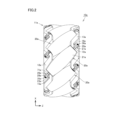
- FIG. 1 is a schematic perspective view showing a wheel according to a first embodiment of the present disclosure.
- FIG. 2 is a schematic side view of the wheel shown in FIG.
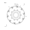
- FIG. 3 is a schematic front view of the wheel shown in FIG.
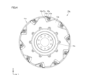
- FIG. 4 is a schematic rear view of the wheel shown in FIG.
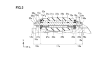
- FIG. 5 is a schematic cross-sectional view showing an enlarged portion of a wheel including one barrel member.
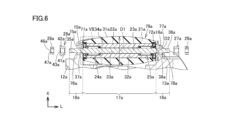
- FIG. 6 is a schematic cross-sectional view showing a state in which a nut and a receiving tool, which will be described later, have been removed from FIG.
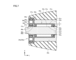
- FIG. 7 is an enlarged view of the area indicated by VII in FIG.
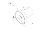
- FIG. 8 is a schematic perspective view showing the appearance of the bearing portion.
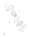
- FIG. 9 is an exploded perspective view of the bearing portion shown in FIG.
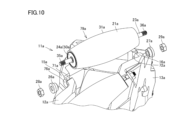
- FIG. 10 is a schematic perspective view showing a portion of the wheel during assembly.
- FIG. 11 is a diagram showing a state in which the structure is assembled into the plate portion.
- the wheel of the present disclosure includes a plurality of barrel members and a wheel body to which the plurality of barrel members are attached on the outer periphery.
- the barrel members include an outer shell portion having an outer periphery with a curved surface and a diameter gradually increasing from both ends of the barrel member in the longitudinal direction toward the center, a barrel shaft extending in the longitudinal direction and arranged to penetrate the outer shell portion in the longitudinal direction and having threads at both ends, a bearing portion for receiving a load applied to the barrel shaft, a pair of receivers each having a through hole into which the barrel shaft is inserted, and a pair of nuts each having a thread groove and attached to the threads of the barrel shaft on the outside of the pair of receivers.
- the wheel body includes a pair of plate portions each rotatably supporting the barrel shaft, and a main body portion holding the pair of plate portions at an interval in the direction of the rotation axis of the wheel.
- Each of the pair of plate portions is provided with a groove portion that is open to the outer diameter side and receives the barrel shaft.
- the barrel shaft with the outer shell attached can be supported by the pair of plate parts using the groove that receives the barrel shaft.
- the groove has a shape that is open to the outer diameter side of the wheel, so the barrel shaft can be easily assembled from the outer diameter side of the wheel.
- the barrel shaft attached to the pair of plate parts can be securely fixed by attaching a receiving tool and tightening it with a nut.
- a load acts on the barrel member in the inner diameter direction, and no load is applied in the outer diameter direction. Therefore, even if a groove is provided on the plate part, there is no problem in terms of strength.
- the barrel shaft can be securely prevented from coming off in the outer diameter direction by the holding tool and the nut.
- the barrel shaft can be securely prevented from falling off while ensuring stable operation of the wheel.
- the receiving tool and the nut can be removed to easily remove the barrel shaft from the outer diameter side of the wheel.
- the receiver may include a small diameter region including one end in the longitudinal direction, and a large diameter region including the other end in the longitudinal direction and having an outer diameter larger than that of the small diameter region.
- the plate portion may be provided with a fitting recess that is recessed in the longitudinal direction from the outer surface and includes a groove portion.
- the small diameter region may be fitted into the fitting recess.
- the wall surface that constitutes the groove may be shaped to extend straight toward the outer diameter side of the wheel. By doing so, the barrel shaft with the outer skin etc. set thereon can be more smoothly inserted into the groove from the outer diameter side of the wheel. This can further improve the ease of assembly.
- the barrel shaft may include a first region sandwiched between a pair of plate portions in the longitudinal direction, and a second region located on both ends of the first region.
- the outer diameter of the first region may be larger than the outer diameter of the second region.
- the groove may receive the barrel shaft in the second region. In this way, it becomes easier to hook the first region onto the pair of plate portions in the longitudinal direction of the barrel shaft, making it easier to restrict longitudinal movement of the barrel shaft. Therefore, more stable wheel operation can be ensured.
- the bearing portion may receive radial loads and thrust loads. In this way, the radial loads and thrust loads applied to the barrel shaft can be properly received by the bearing portion. This ensures more stable wheel operation.
- the bearing portion may be a shell composite roller bearing including a shell outer ring.
- the bearing that receives the radial load and the bearing that receives the thrust load are integrated, which makes it possible to efficiently attach the bearing portion to the barrel shaft and also reduces the number of parts. This can further improve productivity.
- the shell composite roller bearing may include a ring member that also serves as one of the raceways that receives the load in the thrust direction. In this way, the thrust load can be properly received by the ring member. This ensures more stable operation of the wheel.
- the shell composite roller bearing may include a shell outer ring that constitutes an outer ring that receives a radial load.
- the shell outer ring may include a portion located on the outer periphery of the roller that receives a thrust load. In this way, the shell outer ring can integrate the parts located on the outer diameter side of the bearing portion, improving assembly ease. This can further improve productivity.
- the thickness of the shell outer ring may be 0.2 mm or more and 3.2 mm or less. This allows the shell outer ring to be efficiently manufactured by drawing or the like while maintaining the rigidity required for a member constituting a wheel. This allows for improved productivity.
- Fig. 1 is a schematic perspective view showing a wheel in the first embodiment of the present disclosure.
- Fig. 2 is a schematic side view of the wheel shown in Fig. 1.
- Fig. 3 is a schematic front view of the wheel shown in Fig. 1.
- Fig. 4 is a schematic rear view of the wheel shown in Fig. 1.
- the direction indicated by arrow Z is the rotation axis direction of the wheel, and the directions indicated by arrows X and Y are radial directions.
- the direction indicated by arrow X and the direction indicated by arrow Y are perpendicular to each other.
- the wheel 10a of the present disclosure is also called a Mecanum wheel, and is used, for example, as a wheel for a moving object.
- the moving object can be moved in all directions without using a handle.
- Four wheels 10a are attached to the moving object, for example, front, back, left and right.
- the size of the wheel 10a for example the length in the X direction in Figure 2, is 150 mm.
- the wheel 10a includes a plurality of barrel members 20a, ten in this embodiment, and a wheel body 11a to which the plurality of barrel members 20a are attached on the outer periphery.
- the wheel body 11a includes a pair of plate portions 12a, 13a and a main body portion 14a.
- the plate portions 12a, 13a are each disk-shaped and have a through hole in the radial center.
- the plate portion 12a is provided with a support portion 15a that supports the barrel shaft 23a of the barrel member 20a described later.
- the plate portion 13a is provided with a support portion 16a that supports the barrel shaft.
- the pair of plate portions 12a, 13a each rotatably support the barrel shaft.
- the main body portion 14a is cylindrical and has a plurality of mounting holes.
- the main body portion 14a holds the pair of plate portions 12a, 13a at an interval in the rotation axis direction (Z direction) of the wheel 10a.
- the main body portion 14a is connected to a driving source such as a motor (not shown).
- the wheel 10a rotates at a controlled speed and in a controlled direction based on the power transmitted from a motor or the like.
- Figure 5 is a schematic cross-sectional view showing an enlarged portion of a wheel 10a including one barrel member 20a.
- Figure 5 corresponds to a cross-sectional view taken along the central axis of rotation of the barrel member 20a.
- Figure 6 is a schematic cross-sectional view showing the state in Figure 5 after removing receivers 26a, 27a and nuts 28a, 29a, which will be described later.
- Figure 7 is an enlarged view of the area indicated by VII in Figure 6.
- Figure 7 is a schematic cross-sectional view showing an enlarged bearing portion, which will be described later, in Figure 6.
- the longitudinal direction of the barrel member 20a is shown by the direction indicated by arrow L.
- the L direction is inclined at 45 degrees with respect to the Z direction.
- the barrel member 20a includes an outer shell 21a, a core 22a, a barrel shaft 23a, a pair of bearings 24a, 25a, a pair of receivers 26a, 27a, and a pair of nuts 28a, 29a.
- the outer shell 21a has an outer peripheral surface 31a that is curved.
- the diameter of the outer peripheral surface 31a gradually increases from both ends of the longitudinal direction of the barrel member 20a toward the center. That is, the diameter of the barrel member 20a is the largest at the center of the longitudinal direction of the outer shell 21a of the barrel member 20a, and the diameter D2 at both ends of the longitudinal direction of the outer shell 21a of the barrel member 20a is the smallest (see FIG. 6 in particular). In the cross-sections shown in FIGS.
- the outer shell 21a is a barrel-shaped member.
- the outer skin 21a has a hole 32a that penetrates in the longitudinal direction.
- the core 22a is disposed in the hole 32a.
- the outer skin 21a is attached so as to cover the core 22a.
- the longitudinal length of the outer skin 21a is longer than the longitudinal length of the core 22a.
- the outer skin 21a has elasticity. Rubber or resin is selected as the material of the outer skin 21a. In this embodiment, the material of the outer skin 21a is urethane rubber. When resin is used as the material of the outer skin 21a, for example, POM (Poly oxymethylene) resin, PA (Poly amide) resin, or PEEK (Poly Ether Ether Ketone) resin is used.
- the core 22a is composed of a member having rigidity. For example, aluminum-based metal or steel is used as the material of the core 22a, and specifically, A5052 or A6063 is used.
- the barrel shaft 23a is a round bar shaped solid cylinder extending in the longitudinal direction.
- the barrel shaft 23a is arranged so as to penetrate the outer skin 21a in the longitudinal direction.
- the barrel shaft 23a is arranged in a hole 33a that penetrates the core 22a in the longitudinal direction and is provided in the center of the core 22a.
- the outer peripheral surface 34a of the barrel shaft 23a contacts the inner wall surface of the hole 33a. Both ends of the barrel shaft 23a protrude from both end faces of the outer skin 21a and the core 22a.
- Threads 35a, 36a are provided on both ends of the barrel shaft 23a. The areas where the threads 35a, 36a are provided are exposed from both end faces of the core 22a.
- the barrel shaft 23a includes a first region 17a sandwiched between a pair of plate portions 12a, 13a in the longitudinal direction, and a second region 18a located at both ends of the first region 17a.
- the second regions 18a are provided in pairs spaced apart in the longitudinal direction.
- the boundaries between the first region 17a and the pair of second regions 18a are shown by dashed lines in Figures 5 and 6.
- the outer diameter of the first region 17a is larger than the outer diameter of the second regions 18a. This configuration gives the barrel shaft 23a a so-called stepped configuration.
- the outer circumferential surface 34a of the barrel shaft 23a is provided with a pair of circumferential grooves 37a, 38a recessed toward the inner diameter side.
- the circumferential grooves 37a, 38a are formed with a gap in the longitudinal direction.
- the circumferential grooves 37a, 38a are provided in the boundary region between the first region 17a and the second region 18a in the longitudinal direction.
- the circumferential grooves 37a, 38a are used as escape grooves in machining when the barrel shaft 23a is configured with a step.
- the circumferential grooves 37a, 38a are provided toward the center in the longitudinal direction relative to the threads 35a, 36a. In this embodiment, the circumferential grooves 37a, 38a are provided so as to be aligned with both end faces of the outer skin portion 21a in the longitudinal direction.
- receiver 26a and nut 28a will be described.
- the configuration of receiver 27a is similar to that of receiver 26a, so its description will be omitted.
- the configuration of nut 29a is similar to that of nut 28a, so its description will be omitted.
- the receiver 26a is a member also called a collar, and is made of aluminum.
- the receiver 26a may be made of steel.
- the receiver 26a includes a small diameter region 41a including one end in the longitudinal direction, and a large diameter region 42a including the other end in the longitudinal direction and having a larger outer diameter than the small diameter region 41a.
- the receiver 26a is a hollow cylindrical member with a flange portion formed on one end side that extends to the outer diameter side.
- the receiver 26a is provided with a through hole 43a that penetrates in the axial direction.
- the barrel shaft 23a is inserted into this through hole 43a.
- the receiver 26a is attached to the barrel shaft 23a so that the small diameter region 41a is on the inside, i.e., the center side of the barrel shaft 23a.
- the barrel shaft 23a is inserted into the through hole 43a so that the large diameter region 42a faces the one end in the longitudinal direction where the thread 35a is formed, and the receiver 26a is attached to the barrel shaft 23a.
- the barrel shaft 23a is inserted into the through hole 43a so that the large diameter region 42a faces the other end in the longitudinal direction where the thread 36a is formed, and the receiver 27a is attached to the barrel shaft 23a.
- the nut 28a has a thread groove 47a on the inner wall surface that defines the hole 46a.
- the outer shape of the head of the nut 28a is hexagonal when viewed in the longitudinal direction.
- the nut 28a is attached by rotating the nut 28a outside the receiver 27a and tightening the thread groove 47a onto the thread 35a provided on the end of the barrel shaft 23a.
- the nut 29a is attached by rotating the nut 29a outside the receiver 27a and tightening the thread groove 47a onto the thread 36a provided on the end of the barrel shaft 23a.
- bearing portion 24a The configuration of bearing portion 25a is similar to that of bearing portion 24a, so we will not repeat the explanation.
- FIG. 8 is a schematic perspective view showing the appearance of bearing portion 24a.
- FIG. 9 is an exploded perspective view of bearing portion 24a shown in FIG. 8.
- bearing portion 24a receives radial loads and thrust loads.
- Bearing portion 24a is a shell composite roller bearing 50a including a shell outer ring 55a, which will be described later.
- the shell composite roller bearing 50a includes a plurality of first rollers 51a, a plurality of second rollers 52a, a first retainer 53a that holds the plurality of first rollers 51a, a second retainer 54a that holds the plurality of second rollers 52a, a shell outer ring 55a, a raceway ring 56a, and a ring member 57a.
- the first rollers 51a receive a radial load.
- the second rollers 52a receive a thrust load.
- the raceway ring 56a and the ring member 57a are raceways that come into contact with the rolling surfaces of the second rollers 52a and receive a thrust load.
- the shell outer ring 55a includes a first cylindrical portion 61a, a second cylindrical portion 62a, a bottom portion 63a, and a flange portion 64a.
- a hole 65a is provided in the bottom portion 63a, and the barrel shaft 23a is inserted into this hole 65a.
- the first cylindrical portion 61a and the second cylindrical portion 62a are each hollow cylindrical.
- the outer diameter of the second cylindrical portion 62a is larger than the outer diameter of the first cylindrical portion 61a.
- a plurality of first rollers 51a that receive a radial load are arranged on the inner diameter side of the first cylindrical portion 61a.
- the first rollers 51a roll on the outer circumferential surface 34a of the barrel shaft 23a and the inner circumferential surface of the first cylindrical portion 61a as the orbital surface.
- the flange portion 64a is a disk shape that extends from one axial end of the first cylindrical portion 61a to the outer diameter side.
- the flange 64a is provided to connect one axial end of the first cylindrical portion 61a to the other axial end of the second cylindrical portion 62a.
- a plurality of second rollers 52a that receive a thrust load are arranged on the inner diameter side of the second cylindrical portion 62a.
- the thickness T of the shell outer ring 55a is 0.2 mm or more and 3.2 mm or less. In this embodiment, the thickness T of the shell outer ring 55a is 0.5 mm.
- the shell outer ring 55a is constructed as a single piece. The shell outer ring 55a is manufactured, for example, by drawing a steel plate.
- the raceway 56a includes a disk-shaped disk portion 67a with a hole 66a in the center, and a flange portion 68a extending in the thickness direction from the edge of the hole 66a.
- the raceway 56a is attached by inserting the barrel shaft 23a into the hole 66a.
- the ring member 57a is disk-shaped and has a hole 69a in the radial center that penetrates in the thickness direction.
- the ring member 57a is placed in the shell composite roller bearing 50a by inserting the barrel shaft 23a into the hole 66a so that it comes into contact with the flange portion 64a.
- the second roller 52a rolls on one surface of the raceway 56a and the other surface of the ring member 57a as the raceway surface.
- the outer end face of the shell composite roller bearing 50a which is the bearing portion 24a, in this case the end face 58a of the raceway ring 56a opposite the raceway surface, is aligned with the position where the circumferential groove 37a is provided on the outer circumferential surface 34a of the barrel shaft 23a in the longitudinal direction.
- the bearing portion 25a When adjusting the longitudinal gap based on manufacturing errors, etc., a spring washer or a simple washer may be placed so as to come into contact with the end face 58a.
- the pair of plate portions 12a, 13a are each provided with groove portions 71a, 72a that receive the barrel shaft 23a.
- the groove portions 71a, 72a each receive the barrel shaft 23a in the second region 18a.
- the groove portion 71a is provided in a support portion 15a provided on the outer periphery of the plate portion 12a.
- the groove portion 72a is provided in a support portion 16a provided on the outer periphery of the plate portion 13a.
- the groove portions 71a, 72a each have a shape that opens to the outer diameter side.
- the wall surfaces 73a, 74a that constitute the groove portion 71a have a shape that extends straight toward the outer diameter side of the wheel 10a (see particularly Figure 11 described later).
- the grooves 71a and 72a are provided at positions such that the central axis of the barrel shaft 23a, i.e., the central axis of rotation of the barrel member 20a, is inclined at 45 degrees with respect to the rotation axis direction (Z direction) of the wheel 10a.
- ten grooves 71a and 72a are formed in each of the support parts 15a and 16a of the pair of plate parts 12a and 13a so that the central axis of rotation of each of the barrel shafts 23a of the ten barrel members 20a is inclined by 45 degrees.
- the plate portion 12a is provided with an engagement recess 76a that is recessed in the longitudinal direction from the outer surface 75a and includes the groove portion 71a.
- the engagement recess 76a has an annular recessed shape. Specifically, the engagement recess 76a is shaped to receive the small diameter region 41a of the receiver 26a. The small diameter region 41a of the receiver 26a is fitted into the engagement recess 76a.
- the plate portion 13a is provided with an engagement recess 78a that is recessed in the longitudinal direction from the outer surface 77a and includes the groove portion 72a.
- the engagement recess 78a has an annular recessed shape. Specifically, the engagement recess 78a is shaped to receive the small diameter region 41a of the receiver 27a. The small diameter region 41a of the receiver 27a is fitted into the engagement recess 78a.
- Each plate portion 12a, 13a has ten mating recesses 76a, 78a formed therein, which correspond to the ten barrel
- FIG. 10 is a schematic perspective view showing a part of the wheel 10a when assembling the wheel 10a.
- the receivers 26a, 27a and nuts 28a, 29a are removed, that is, a structure 79a is prepared by combining the outer shell 21a, core 22a, barrel shaft 23a, and bearings 24a, 25a.
- a structure 79a is prepared by combining the outer shell 21a, core 22a, barrel shaft 23a, and bearings 24a, 25a.
- both ends of the barrel shaft 23a protrude in the longitudinal direction.
- FIG. 11 is a diagram showing the state in which the structure 79a is assembled into the plate portion 12a.
- the central axis of the barrel shaft 23a is inclined at 45 degrees with respect to the Z direction. Since the grooves 71a and 72a are each open to the outer diameter side, the barrel shaft 23a can be easily inserted from the outer diameter side as shown by the arrow.
- the receivers 26a and 27a are attached from both sides in the longitudinal direction.
- one end of the barrel shaft 23a is inserted into the through hole 43a from the small diameter region 41a side of the receiver 26a, and the other end of the barrel shaft 23a is inserted into the through hole 43a from the small diameter region 41a side of the receiver 27a.
- the small diameter regions 41a of the receivers 26a and 27a are fitted into the fitting recesses 76a and 78a provided in the plate portions 12a and 13a, respectively.
- the receivers 26a and 27a are attached to the barrel shaft 23a.
- the nuts 28a and 29a are attached to both ends of the barrel shaft 23a.
- the nuts 28a and 29a are rotated and tightened to fix the barrel member 20a to the pair of plate portions 12a and 13a. In this way, all of the ten barrel members 20a are fixed to the plate portions 12a and 13a, and the wheel 10a is assembled.
- the process is reversed. That is, the nuts 28a, 29a are rotated in the reverse direction to remove the nuts 28a, 29a from both ends of the barrel shaft 23a. This releases the barrel member 20a from being fixed to the plate portions 12a, 13a.
- the receivers 26a, 27a are moved in the longitudinal direction to remove them.
- the structure 79a including the barrel shaft 23a is moved toward the outer diameter side to remove it.
- the barrel shaft 23a with the outer skin 21a attached can be supported by the pair of plate parts 12a, 13a using the grooves 71a, 72a that receive the barrel shaft 23a.
- the grooves 71a, 72a are open to the outer diameter side of the wheel 10a, so the barrel shaft 23a can be easily assembled from the outer diameter side of the wheel 10a.
- the barrel shaft 23a attached to the pair of plate parts 12a, 13a can be securely fixed by attaching the receivers 26a, 27a and tightening them with the nuts 28a, 29a. In this case, when the wheel 10a is in operation, a load acts on the barrel member 20a in the inner diameter direction, and no load is applied in the outer diameter direction.
- the barrel shaft 23a can be reliably prevented from coming off in the longitudinal direction by the receiving parts 26a, 27a and the nuts 28a, 29a. As a result, the barrel shaft 23a can be reliably prevented from falling off while ensuring stable operation of the wheel 10a. In addition, the barrel shaft 23a can be easily removed from the outer diameter side of the wheel 10a by removing the receiving parts 26a, 27a and the nuts 28a, 29a.
- the receivers 26a, 27a include a small diameter region 41a including one end in the longitudinal direction, and a large diameter region 42a including the other end in the longitudinal direction and having a larger outer diameter than the small diameter region 41a.
- the plate portions 12a, 13a are provided with fitting recesses 76a, 78a that are recessed in the longitudinal direction from the outer surfaces 75a, 77a and include the grooves 71a, 72a.
- the small diameter region 41a is fitted into the fitting recesses 76a, 78a.
- the small diameter region 41a of the receivers 26a, 27a can be fitted into the fitting recesses 76a, 78a to fix the receivers 26a, 27a to the plate portions 12a, 13a. Therefore, the barrel shaft 23a can be supported more stably, and smoother rotation of the barrel member 20a can be ensured.
- the wall surfaces 73a, 74a that form the grooves 71a, 72a are shaped to extend straight toward the outer diameter side of the wheel 10a. This allows the barrel shaft 23a, to which the outer skin 21a and the like are attached, to be more smoothly inserted into the grooves 71a, 72a from the outer diameter side of the wheel 10a. This further improves ease of assembly.
- the barrel shaft 23a includes a first region 17a sandwiched between a pair of plate portions 12a, 13a in the longitudinal direction, and a second region 18a located on both ends of the first region 17a.
- the outer diameter of the first region 17a is larger than the outer diameter of the second region 18a.
- the grooves 71a, 72a receive the barrel shaft 23a in the second region 18a. This makes it easier to hook the first region 17a onto the pair of plate portions 12a, 13a in the longitudinal direction of the barrel shaft 23a, making it easier to restrict longitudinal movement of the barrel shaft 23a. This ensures more stable operation of the wheel 10a.
- the bearings 24a and 25a receive radial and thrust loads. Therefore, the radial and thrust loads applied to the barrel shaft 23a can be appropriately received by the bearings 24a and 25a. This ensures more stable operation of the wheel 10a.
- the bearings 24a, 25a are shell composite roller bearings 50a that include a shell outer ring. Therefore, the bearing that receives the radial load and the bearing that receives the thrust load are integrated, which makes it possible to efficiently attach the bearings 24a, 25a to the barrel shaft 23a and also reduces the number of parts. This further improves productivity.
- the shell composite roller bearing 50a includes a ring member 57a that also serves as one of the raceways that receives the load in the thrust direction. Therefore, the thrust load can be properly received by the ring member 57a. This ensures more stable operation of the wheel 10a.
- the shell composite roller bearing 50a includes a shell outer ring 55a that constitutes the outer ring that receives the radial load.
- the shell outer ring 55a includes a portion that is located on the outer periphery of the roller (second roller 52a) that receives the thrust load. Therefore, the shell outer ring 55a makes it possible to integrate the parts located on the outer diameter side of the bearing portions 24a and 25a, thereby improving the ease of assembly. This in turn makes it possible to further improve productivity.
- the thickness T of the shell outer ring 55a is 0.2 mm or more and 3.2 mm or less. Therefore, the shell outer ring 55a can be efficiently manufactured by drawing or the like while maintaining the rigidity required as a component of the wheel 10a. This allows for improved productivity.
- the bearing portion includes a ring member, but this is not limiting, and the bearing portion may be configured not to include a ring member.
- the flange portion of the shell outer ring may be used as one of the raceways that receives the load in the thrust direction.
- the bearing portion is a shell composite roller bearing, but this is not limited thereto, and the bearing portion may be configured by combining a radial bearing that receives radial loads and a thrust bearing that receives thrust loads. Also, either one of the bearings may not include rollers or other rolling elements, and may be configured as a sliding bearing.
Landscapes
- Engineering & Computer Science (AREA)
- Mechanical Engineering (AREA)
- Rolling Contact Bearings (AREA)
Abstract
ホイールは、複数のバレル部材と、ホイール体と、を備える。バレル部材は、外皮部と、バレルシャフトと、軸受部と、それぞれ貫通穴が設けられており、貫通穴にバレルシャフトが挿入される一対の受け具と、それぞれねじ溝が設けられ、それぞれ一対の受け具の外側においてバレルシャフトのねじ山に取り付けられる一対のナットと、を含む。ホイール体は、それぞれバレルシャフトを回転可能に支持する一対のプレート部と、一対のプレート部をホイールの回転軸方向に間隔をあけて保持する本体部と、を含む。一対のプレート部にはそれぞれ、外径側に開放され、バレルシャフトを受け入れる溝部が設けられる。
Description
本開示は、ホイールに関するものである。本出願は、2023年6月16日出願の日本出願第2023-99154号に基づく優先権を主張し、前記日本出願に記載された全ての記載内容を援用するものである。
複数のバレル部材を備えるホイールが開示されている(例えば特許文献1または特許文献2参照)。
複数のバレル部材を備えるホイールについては、メカナムホイールとして移動体に組み込まれた際に、安定して動作することが求められる。また、ホイールには、複数のバレル部材が組み込まれるが、一部のバレル部材を交換したい場合が生じる。このようなときに、バレル部材の容易な着脱を可能にする良好な組み立て性も求められる。
そこで、安定した動作を確保することができると共に、組み立て性を良好にすることができるホイールを提供することを目的の1つとする。
本開示に従ったホイールは、複数のバレル部材と、複数のバレル部材が外周側に取り付けられるホイール体と、を備える。バレル部材は、曲面で構成されており、バレル部材の長手方向の両端から中央に向かって直径が徐々に大きくなる外周面を有する外皮部と、長手方向に延び、外皮部を長手方向に貫通するように配置され、両端部にねじ山が設けられるバレルシャフトと、バレルシャフトに負荷される荷重を受ける軸受部と、それぞれ貫通穴が設けられており、貫通穴にバレルシャフトが挿入される一対の受け具と、それぞれねじ溝が設けられ、それぞれ一対の受け具の外側においてバレルシャフトのねじ山に取り付けられる一対のナットと、を含む。ホイール体は、それぞれバレルシャフトを回転可能に支持する一対のプレート部と、一対のプレート部をホイールの回転軸方向に間隔をあけて保持する本体部と、を含む。一対のプレート部にはそれぞれ、外径側に開放され、バレルシャフトを受け入れる溝部が設けられる。
上記ホイールによれば、安定した動作を確保することができると共に、組み立て性を良好にすることができる。
[実施形態の概要]
本開示のホイールは、複数のバレル部材と、複数のバレル部材が外周側に取り付けられるホイール体と、を備える。バレル部材は、曲面で構成されており、バレル部材の長手方向の両端から中央に向かって直径が徐々に大きくなる外周面を有する外皮部と、長手方向に延び、外皮部を長手方向に貫通するように配置され、両端部にねじ山が設けられるバレルシャフトと、バレルシャフトに負荷される荷重を受ける軸受部と、それぞれ貫通穴が設けられており、貫通穴にバレルシャフトが挿入される一対の受け具と、それぞれねじ溝が設けられ、それぞれ一対の受け具の外側においてバレルシャフトのねじ山に取り付けられる一対のナットと、を含む。ホイール体は、それぞれバレルシャフトを回転可能に支持する一対のプレート部と、一対のプレート部をホイールの回転軸方向に間隔をあけて保持する本体部と、を含む。一対のプレート部にはそれぞれ、外径側に開放され、バレルシャフトを受け入れる溝部が設けられる。
本開示のホイールは、複数のバレル部材と、複数のバレル部材が外周側に取り付けられるホイール体と、を備える。バレル部材は、曲面で構成されており、バレル部材の長手方向の両端から中央に向かって直径が徐々に大きくなる外周面を有する外皮部と、長手方向に延び、外皮部を長手方向に貫通するように配置され、両端部にねじ山が設けられるバレルシャフトと、バレルシャフトに負荷される荷重を受ける軸受部と、それぞれ貫通穴が設けられており、貫通穴にバレルシャフトが挿入される一対の受け具と、それぞれねじ溝が設けられ、それぞれ一対の受け具の外側においてバレルシャフトのねじ山に取り付けられる一対のナットと、を含む。ホイール体は、それぞれバレルシャフトを回転可能に支持する一対のプレート部と、一対のプレート部をホイールの回転軸方向に間隔をあけて保持する本体部と、を含む。一対のプレート部にはそれぞれ、外径側に開放され、バレルシャフトを受け入れる溝部が設けられる。
本開示のホイールによると、外皮部を取り付けたバレルシャフトを、バレルシャフトを受け入れる溝部を利用して、一対のプレート部に支持させることができる。溝部は、ホイールの外径側に開放された形状であるため、ホイールの外径側から容易にバレルシャフトを組み込むことができる。バレルシャフトを組み込んだ後、受け具を装着してナットで締め付けることにより、一対のプレート部に取り付けたバレルシャフトを確実に固定することができる。この場合、ホイールの動作時において、バレル部材には内径方向の負荷が作用し、外径方向には負荷がかからない。したがって、プレート部に溝部が設けられていても、強度的に問題はない。したがって、受け具を挿入したプレート部の破損を回避しながら、受け具およびナットによる保持によって確実にバレルシャフトの外径方向への抜けを抑制することができる。その結果、ホイールの安定した動作を確保しながら、バレルシャフトの脱落を確実に抑制することができる。また、受け具およびナットを取り外して、ホイールの外径側から容易にバレルシャフトを取り外すことができる。すなわち、例えば全てのバレルシャフトの固定を解除して一方のプレート部を本体部から取り外すといった大掛かりな分解を要する作業が生じることはない。したがって、バレル部材の交換も容易に行うことができる。以上より、このようなホイールによると、安定した動作を確保することができると共に、組み立て性を良好にすることができる。
上記ホイールにおいて、受け具は、長手方向の一方側の端部を含む小径領域と、長手方向の他方側の端部を含み、小径領域よりも外径の大きい大径領域と、を含んでもよい。プレート部には、外側面から長手方向に凹み、溝部を含むように嵌合凹部が設けられてもよい。小径領域は、嵌合凹部に嵌め込まれてもよい。このようにすることにより、受け具の小径領域を嵌合凹部に嵌め込んで、受け具をプレート部に固定することができる。したがって、バレルシャフトをより安定して支持することができ、より円滑なバレル部材の回転を確保することができる。
上記ホイールにおいて、溝部を構成する壁面は、ホイールの外径側に真っ直ぐに延びる形状であってもよい。このようにすることにより、ホイールの外径側から、外皮部等をセットしたバレルシャフトをより円滑に溝部内に組み込むことができる。したがって、より組み立て性の向上を図ることができる。
上記ホイールにおいて、バレルシャフトは、長手方向において、一対のプレート部に挟まれる第1領域と、第1領域の両端側に位置する第2領域と、を含んでもよい。第1領域の外径は、第2領域の外径よりも大きくてもよい。溝部は、第2領域においてバレルシャフトを受け入れてもよい。このようにすることにより、バレルシャフトの長手方向において、第1領域を一対のプレート部に引っ掛かかるようにすることが容易になり、バレルシャフトの長手方向の移動を規制しやすくなる。したがって、より安定したホイールの動作を確保することができる。
上記ホイールにおいて、軸受部は、ラジアル方向の荷重およびスラスト方向の荷重を受けてもよい。このようにすることにより、バレルシャフトに負荷されるラジアル荷重およびスラスト荷重を軸受部によって適切に受けることができる。したがって、より安定したホイールの動作を確保することができる。
上記ホイールにおいて、軸受部は、シェル外輪を含むシェル複合形ローラベアリングであってもよい。このようにすることにより、ラジアル方向の荷重を受ける軸受およびスラスト方向の荷重を受ける軸受を一体化して、バレルシャフトへの軸受部の取り付けの効率化を図ることができると共に、部品点数の削減を図ることができる。したがって、より生産性の向上を図ることができる。
上記ホイールにおいて、シェル複合形ローラベアリングは、スラスト方向の荷重を受ける一方の軌道輪を兼ねるリング部材を含んでもよい。このようにすることにより、スラスト荷重をリング部材により適切に受けることができる。したがって、より安定してホイールの動作を確保することができる。
上記ホイールにおいて、シェル複合形ローラベアリングは、ラジアル方向の荷重を受ける外輪を構成するシェル外輪を含んでもよい。シェル外輪は、スラスト方向の荷重を受けるローラの外周側に位置する部分を含んでもよい。このようにすることにより、シェル外輪により、軸受部の外径側に位置するパーツを一体化することができるため、組み立て性の向上を図ることができる。したがって、より生産性の向上を図ることができる。
上記ホイールにおいて、シェル外輪の厚さは、0.2mm以上3.2mm以下であってもよい。このようにすることにより、ホイールを構成する部材として求められる剛性を維持しつつ、絞り加工等によって製造されるシェル外輪を効率的に製造することができる。したがって、生産性の向上を図ることができる。
[実施形態の具体例]
次に、本開示のホイールの具体的な実施の形態の一例を、図面を参照しつつ説明する。以下の図面において同一または相当する部分には同一の参照番号を付しその説明は繰返さない。
次に、本開示のホイールの具体的な実施の形態の一例を、図面を参照しつつ説明する。以下の図面において同一または相当する部分には同一の参照番号を付しその説明は繰返さない。
(実施の形態1)
まず、本開示の実施の形態である実施の形態1について説明する。図1は、本開示の実施の形態1におけるホイールを示す概略斜視図である。図2は、図1に示すホイールの概略側面図である。図3は、図1に示すホイールの概略正面図である。図4は、図1に示すホイールの概略背面図である。図1以下に示す図において、矢印Zで示す方向をホイールの回転軸方向、矢印Xおよび矢印Yで示す方向を径方向とする。矢印Xで示す方向および矢印Yで示す方向は、直交している。
まず、本開示の実施の形態である実施の形態1について説明する。図1は、本開示の実施の形態1におけるホイールを示す概略斜視図である。図2は、図1に示すホイールの概略側面図である。図3は、図1に示すホイールの概略正面図である。図4は、図1に示すホイールの概略背面図である。図1以下に示す図において、矢印Zで示す方向をホイールの回転軸方向、矢印Xおよび矢印Yで示す方向を径方向とする。矢印Xで示す方向および矢印Yで示す方向は、直交している。
図1~図4を参照して、本開示のホイール10aは、メカナムホイールとも称され、例えば、移動体の車輪として利用される。複数のメカナムホイールを組み合わせてそれぞれの回転数や回転方向等を制御することにより、ハンドルを用いなくとも全方向に移動体を移動させることができる。移動体には、例えば前後左右に4つのホイール10aが取り付けられる。ホイール10aの大きさ、例えば図2におけるX方向の長さは、150mmである。
ホイール10aは、複数、本実施形態においては、10個のバレル部材20aと、複数のバレル部材20aが外周側に取り付けられるホイール体11aと、を含む。ホイール体11aは、一対のプレート部12a,13aと、本体部14aと、を含む。プレート部12a,13aはそれぞれ円板状であって、径方向の中央に貫通穴が設けられている。プレート部12aは、後述するバレル部材20aのバレルシャフト23aを支持する支持部15aが設けられている。同様に、プレート部13aには、バレルシャフトを支持する支持部16aが設けられている。一対のプレート部12a,13aは、それぞれバレルシャフトを回転可能に支持する。本体部14aは円筒状であって、複数の取り付け穴が設けられている。本体部14aは、一対のプレート部12a、13aをホイール10aの回転軸方向(Z方向)に間隔をあけて保持する。本体部14aは、図示しないモータ等の駆動源に連結される。ホイール10aは、モータ等から伝達された動力を基に、制御された回転数や回転方向で回転する。
図5は、1つのバレル部材20aを含むホイール10aに一部を拡大して示す概略断面図である。図5は、バレル部材20aの回転中心軸に沿って切断した場合の断面図に相当する。図6は、図5において、後述する受け具26a,27aおよびナット28a,29aを取り外した状態を示す概略断面図である。図7は、図6中のVIIで示す領域の拡大図である。図7は、図6において、後述する軸受部を拡大した概略断面図である。図5、図6および図7において、バレル部材20aの長手方向を、矢印Lで示す方向によって図示する。L方向は、Z方向に対して45度傾斜している。
図5、図6および図7を併せて参照して、バレル部材20aは、外皮部21aと、芯部22aと、バレルシャフト23aと、一対の軸受部24a,25aと、一対の受け具26a,27aと、一対のナット28a,29aと、を含む。外皮部21aは、曲面で構成されている外周面31aを有する。外周面31aは、バレル部材20aの長手方向の両端から中央に向かって直径が徐々に大きくなる。すなわち、バレル部材20aの直径については、バレル部材20aの外皮部21aの長さ方向の中央における直径D1が最も大きく、バレル部材20aの外皮部21aの長さ方向の両端における直径D2が最も小さい(特に図6参照)。図5および図6に示す断面において、外皮部21aの外周面31aは、長手方向の中央に向かう程、曲率半径が大きくなっている。外皮部21aは、樽状の部材である。外皮部21aには、長手方向に貫通する穴32aが設けられている。穴32a内に芯部22aが配置される。芯部22aを覆うように外皮部21aが取り付けられている。外皮部21aの長手方向の長さは、芯部22aの長手方向の長さよりも長い。
外皮部21aは、弾性を有する。外皮部21aの材質としては、ゴムや樹脂が選択される。本実施形態においては、外皮部21aの材質は、ウレタンゴムである。外皮部21aの材質として樹脂を採用する場合、例えば、POM(Poly oxymethylene)樹脂やPA(Poly amide)樹脂、PEEK(Poly Ether EtherKetone)樹脂が用いられる。また、芯部22aは、剛性を有する部材から構成されている。芯部22aの材質としては、例えばアルミニウムをベースとした金属や鋼が用いられ、具体的にはA5052やA6063が採用される。
バレルシャフト23aは、丸棒状であって、長手方向に延びる中実円筒状である。バレルシャフト23aは、外皮部21aを長手方向に貫通するように配置される。具体的には、バレルシャフト23aは、芯部22aの中央に設けられた長手方向に貫通する穴33a内に配置される。バレルシャフト23aの外周面34aは、穴33aの内壁面と接触する。バレルシャフト23aの両端は、外皮部21aおよび芯部22aのそれぞれの両端面から突き出る。バレルシャフト23aの両端部には、ねじ山35a,36aが設けられる。ねじ山35a,36aが設けられる領域は、芯部22aの両端面からそれぞれ露出している。
バレルシャフト23aは、長手方向において、一対にプレート部12a,13aに挟まれる第1領域17aと、第1領域17aの両端側に位置する第2領域18aと、を含む。第2領域18aは、長手方向において間隔をあけて一対設けられる。第1領域17aおよび一対の第2領域18aのそれぞれの境界は、図5および図6において破線で図示している。第1領域17aの外径は、第2領域18aの外径よりも大きい。このような構成により、バレルシャフト23aは、いわゆる段付きの構成となる。
バレルシャフト23aの外周面34aには、内径側に凹む一対の円周溝37a,38aが設けられる。円周溝37a,38aはそれぞれ、長手方向に間隔をあけて形成されている。円周溝37a,38aはそれぞれ、長手方向において、第1領域17aと第2領域18aとの境界の領域に設けられる。この円周溝37a,38aは、バレルシャフト23aを段付きの構成とする際の加工上の逃がし溝として利用される。円周溝37a,38aは、ねじ山35a,36aよりも長手方向の中央側に設けられる。なお、本実施形態においては、円周溝37a,38aは、長手方向において、外皮部21aの両端面と揃うように設けられる。
次に、受け具26aおよびナット28aの構成について説明する。受け具27aの構成は、受け具26aの構成と同様であるため、その説明を省略する。また、ナット29aの構成は、ナット28aの構成と同様であるため、その説明を省略する。
受け具26aは、カラーとも呼ばれる部材であり、アルミニウム製である。なお、受け具26aは、鋼製であってもよい。受け具26aは、長手方向の一方側の端部を含む小径領域41aと、長手方向の他方側の端部を含み、小径領域41aよりも外径の大きい大径領域42aと、を含む。受け具26aは、中空円筒状の部材において、一方の端部側に外径側に延びる鍔部を形成した形状である。受け具26aには、軸方向に貫通する貫通穴43aが設けられている。この貫通穴43aに、バレルシャフト23aが挿入される。受け具26aは、小径領域41aが内側、すなわち、バレルシャフト23aの中央側となるようにバレルシャフト23aに取り付けられる。ねじ山35aが形成されている長手方向の一方端部側に大径領域42aが向くように貫通穴43aにバレルシャフト23aを挿入して、受け具26aをバレルシャフト23aに装着する。受け具27aについても同様に、ねじ山36aが形成されている長手方向の他方端部側に大径領域42aが向くように貫通穴43aにバレルシャフト23aを挿入して、受け具27aをバレルシャフト23aに装着する。
ナット28aは、穴46aを構成する内壁面にねじ溝47aが設けられている。ナット28aの頭部の外形形状は、長手方向に見て六角形である。ナット28aは、受け具27aの外側においてナット28aを回転させ、バレルシャフト23aの端部に設けられるねじ山35aにねじ溝47aを締め付けて取り付けられる。ナット29aについても同様に、受け具27aの外側においてナット29aを回転させ、バレルシャフト23aの端部に設けられるねじ山36aにねじ溝47aを締め付けて取り付けられる。
ここで、軸受部24aの構成について説明する。軸受部25aの構成は、軸受部24aの構成と同様であるため、その説明を省略する。
図8は、軸受部24aの外観を示す概略斜視図である。図9は、図8に示す軸受部24aの分解斜視図である。なお、理解を容易にする観点から、軸受部24aの取り付け時の方向を、図5~図7で示す矢印Lを用いて図示している。図8および図9を併せて参照して、軸受部24aは、ラジアル方向の荷重およびスラスト方向の荷重を受ける。軸受部24aは、後述するシェル外輪55aを含むシェル複合形ローラベアリング50aである。
シェル複合形ローラベアリング50aは、複数の第1ローラ51aと、複数の第2ローラ52aと、複数の第1ローラ51aを保持する第1保持器53aと、複数の第2ローラ52aを保持する第2保持器54aと、シェル外輪55aと、軌道輪56aと、リング部材57aと、を含む。第1ローラ51aは、ラジアル方向の荷重を受ける。第2ローラ52aは、スラスト方向の荷重を受ける。軌道輪56aおよびリング部材57aは、それぞれ第2ローラ52aの転動面と接触して、スラスト方向の荷重を受ける軌道輪である。
次に、シェル外輪55aの構成について簡単に説明する。シェル外輪55aは、第1円筒部61aと、第2円筒部62aと、底部63aと、鍔部64aと、を含む。底部63aには、穴65aが設けられており、この穴65aにバレルシャフト23aが挿入される。第1円筒部61aおよび第2円筒部62aはそれぞれ、中空円筒状である。第2円筒部62aの外径は、第1円筒部61aの外径よりも大きい。第1円筒部61aの内径側にラジアル方向の荷重を受ける複数の第1ローラ51aが配置される。第1ローラ51aは、バレルシャフト23aの外周面34aと第1円筒部61aの内周面を軌道面として転動する。鍔部64aは、第1円筒部61aの軸方向の一方端部から外径側に延びる円板状である。鍔部64aは、第1円筒部61aの軸方向の一方端部と第2円筒部62aの軸方向の他方端部とを接続するように設けられている。第2円筒部62aの内径側にスラスト方向の荷重を受ける複数の第2ローラ52aが配置される。
シェル外輪55aの厚さTは、0.2mm以上3.2mm以下である。本実施形態においては、シェル外輪55aの厚さTは、0.5mmである。シェル外輪55aは、一体で構成されている。シェル外輪55aは、例えば、鋼鈑の絞り加工等により製造される。
軌道輪56aは、中央に穴66aが設けられた円板状の円板部67aと、穴66aの縁から厚さ方向に延びる鍔部68aと、を含む。軌道輪56aは、穴66a内にバレルシャフト23aを挿入して取り付けられる。リング部材57aは、円板状であって、厚さ方向に貫通する穴69aが径方向の中央に設けられている。リング部材57aは、穴66a内にバレルシャフト23aを挿入し、鍔部64aと接触するようにして、シェル複合形ローラベアリング50a内に配置される。第2ローラ52aは、軌道輪56aの一方の面とリング部材57aの他方の面を軌道面として転動する。
また、本実施形態においては、長手方向において、軸受部24aであるシェル複合形ローラベアリング50aの外側の端面、この場合、軌道輪56aのうちの軌道面と反対側の端面58aは、バレルシャフト23aの外周面34aの円周溝37aが設けられた位置と揃えて配置される。軸受部25aについても同様である。なお、製造誤差等に基づく長手方向における隙間を調整する際に、端面58aに接触するようにスプリングワッシャや単なるワッシャを配置することにしてもよい。
次に、再びホイール体11aの構成について説明する。一対のプレート部12a,13aにはそれぞれ、バレルシャフト23aを受け入れる溝部71a,72aが設けられる。本実施形態においては、溝部71a,72aはそれぞれ、第2領域18aにおいてバレルシャフト23aを受け入れる。溝部71aは、プレート部12aの外周側に設けられた支持部15aに設けられる。溝部72aは、プレート部13aの外周側に設けられた支持部16aに設けられる。溝部71a,72aはそれぞれ、外径側に開放される形状である。本実施形態においては、溝部71aを構成する壁面73a,74aは、ホイール10aの外径側に真っ直ぐに延びる形状である(特に後述する図11参照)。溝部71a,72aは、バレルシャフト23aの中心軸、すなわち、バレル部材20aの回転中心軸をホイール10aの回転軸方向(Z方向)に対して、45度傾斜するような位置に設けられる。すなわち、10個のバレル部材20aのそれぞれのバレルシャフト23aの回転中心軸を45度ずつ傾斜させるように、一対のプレート部12a,13aのそれぞれの支持部15a,16aには、それぞれ10個の溝部71a,72aが形成されている。
また、プレート部12aには、外側面75aから長手方向に凹み、溝部71aを含むように嵌合凹部76aが設けられる。嵌合凹部76aは、環状に凹んだ形状である。具体的には、嵌合凹部76aは、受け具26aの小径領域41aを受け入れる形状である。受け具26aの小径領域41aは、嵌合凹部76aに嵌め込まれる。プレート部13aには、外側面77aから長手方向に凹み、溝部72aを含むように嵌合凹部78aが設けられる。嵌合凹部78aは、環状に凹んだ形状である。具体的には、嵌合凹部78aは、受け具27aの小径領域41aを受け入れる形状である。受け具27aの小径領域41aは、嵌合凹部78aに嵌め込まれる。各プレート部12a,13aには、10個のバレル部材20aに対応する嵌合凹部76a,78aがそれぞれ10個形成されている。
次に、このような構成のホイール10aの組み立て方法について、簡単に説明する。図10は、ホイール10aを組み立てる際のホイール10aの一部を示す概略斜視図である。図10を併せて参照して、まず、受け具26a,27aおよびナット28a,29aを取り除いた状態、すなわち、外皮部21a、芯部22a、バレルシャフト23a、軸受部24a,25aを組み合わせた構造体79aを準備する。この構造体79aにおいては、バレルシャフト23aの両端が、長手方向に突出する。
その後、長手方向に突出したバレルシャフト23aの両端を溝部71a,72a内に挿入する。図11は、プレート部12aに構造体79aを組み込む状態を示す図である。図11を併せて参照して、この場合、バレルシャフト23aの中心軸は、Z方向に対して45度傾斜した状態である。そして、溝部71a,72aはそれぞれ外径側に開放されているため、矢印で示すように、外径側から容易にバレルシャフト23aを挿入することができる。次に、長手方向の両側から受け具26a,27aを装着する。具体的には、受け具26aの小径領域41a側から貫通穴43aにバレルシャフト23aの一方端部から差し込み、受け具27aの小径領域41a側から貫通穴43aにバレルシャフト23aの他方端部を差し込む。この時、受け具26a,27aの小径領域41aはそれぞれ、プレート部12a,13aに設けられた嵌合凹部76a,78aに嵌め込まれる。このようにして、受け具26a,27aをバレルシャフト23aに装着する。そして最後に、ナット28a,29aをバレルシャフト23aの両端に取り付ける。ナット28a,29aを回転させて締め込んでいき、バレル部材20aを一対のプレート部12a,13aに固定する。このようにして全て、すなわち、10個のバレル部材20aをプレート部12a,13aに固定し、ホイール10aを組み立てる。
なお、バレル部材20aの取り外し時においては、逆の工程で行う。すなわち、ナット28a,29aを逆回転させてバレルシャフト23aの両端からナット28a,29aを取り外す。そうすると、バレル部材20aのプレート部12a,13aへの固定が解除される。次に、受け具26a,27aを長手方向に動かして取り外す。そうすると、溝部71a,72a内にバレルシャフト23aが挿入された状態であるため、外径側へバレルシャフト23aを含む構造体79aを動かして、取り外す。
上記ホイール10aによると、外皮部21aを取り付けたバレルシャフト23aを、バレルシャフト23aを受け入れる溝部71a,72aを利用して、一対のプレート部12a,13aに支持させることができる。溝部71a,72aは、ホイール10aの外径側に開放された形状であるため、ホイール10aの外径側から容易にバレルシャフト23aを組み込むことができる。バレルシャフト23aを組み込んだ後、受け具26a,27aを装着してナット28a,29aで締め付けることにより、一対のプレート部12a,13aに取り付けたバレルシャフト23aを確実に固定することができる。この場合、ホイール10aの動作時において、バレル部材20aには内径方向の負荷が作用し、外径方向には負荷がかからない。したがって、プレート部12a,13aに溝部71a,72aが設けられていても、強度的に問題はない。したがって、受け具26a,27aを挿入したプレート部12a,13aの破損を回避しながら、受け具26a,27aおよびナット28a,29aによる保持によって確実にバレルシャフト23aの長手方向における抜けを抑制することができる。その結果、ホイール10aの安定した動作を確保しながら、バレルシャフト23aの脱落を確実に抑制することができる。また、受け具26a,27aおよびナット28a,29aを取り外して、ホイール10aの外径側から容易にバレルシャフト23aを取り外すことができる。すなわち、例えば全てのバレルシャフト23aの固定を解除して一方のプレート部12aを本体部14aから取り外すといった大掛かりな分解を要する作業が生じることはない。したがって、バレル部材20aの交換も容易に行うことができる。以上より、このようなホイール10aによると、安定した動作を確保することができると共に、組み立て性を良好にすることができる。
本実施形態においては、受け具26a,27aは、長手方向の一方側の端部を含む小径領域41aと、長手方向の他方側の端部を含み、小径領域41aよりも外径の大きい大径領域42aと、を含む。プレート部12a,13aには、外側面75a,77aから長手方向に凹み、溝部71a,72aを含むように嵌合凹部76a,78aが設けられる。小径領域41aは、嵌合凹部76a,78aに嵌め込まれる。よって、受け具26a,27aの小径領域41aを嵌合凹部76a,78aに嵌め込んで、受け具26a,27aをプレート部12a,13aに固定することができる。したがって、バレルシャフト23aをより安定して支持することができ、より円滑なバレル部材20aの回転を確保することができる。
本実施形態においては、溝部71a,72aを構成する壁面73a,74aは、ホイール10aの外径側に真っ直ぐに延びる形状である。よって、ホイール10aの外径側から、外皮部21a等をセットしたバレルシャフト23aをより円滑に溝部71a,72a内に組み込むことができる。したがって、より組み立て性の向上を図ることができる。
本実施形態においては、バレルシャフト23aは、長手方向において、一対のプレート部12a,13aに挟まれる第1領域17aと、第1領域17aの両端側に位置する第2領域18aと、を含む。第1領域17aの外径は、第2領域18aの外径よりも大きい。溝部71a,72aは、第2領域18aにおいてバレルシャフト23aを受け入れる。よって、バレルシャフト23aの長手方向において、第1領域17aを一対のプレート部12a,13aに引っ掛かかるようにすることが容易になり、バレルシャフト23aの長手方向の移動を規制しやすくなる。したがって、より安定したホイール10aの動作を確保することができる。
本実施形態においては、軸受部24a,25aは、ラジアル方向の荷重およびスラスト方向の荷重を受ける。よって、バレルシャフト23aに負荷されるラジアル荷重およびスラスト荷重を軸受部24a,25aによって適切に受けることができる。したがって、より安定したホイール10aの動作を確保することができる。
本実施形態においては、軸受部24a,25aは、シェル外輪を含むシェル複合形ローラベアリング50aである。よって、ラジアル方向の荷重を受ける軸受およびスラスト方向の荷重を受ける軸受を一体化して、バレルシャフト23aへの軸受部24a,25aの取り付けの効率化を図ることができると共に、部品点数の削減を図ることができる。したがって、より生産性の向上を図ることができる。
本実施形態においては、シェル複合形ローラベアリング50aは、スラスト方向の荷重を受ける一方の軌道輪を兼ねるリング部材57aを含む。よって、スラスト荷重をリング部材57aにより適切に受けることができる。したがって、より安定してホイール10aの動作を確保することができる。
本実施形態においては、シェル複合形ローラベアリング50aは、ラジアル方向の荷重を受ける外輪を構成するシェル外輪55aを含む。シェル外輪55aは、スラスト方向の荷重を受けるローラ(第2ローラ52a)の外周側に位置する部分を含む。よって、シェル外輪55aにより、軸受部24a,25aの外径側に位置するパーツを一体化することができるため、組み立て性の向上を図ることができる。したがって、より生産性の向上を図ることができる。
本実施形態においては、シェル外輪55aの厚さTは、0.2mm以上3.2mm以下である。よって、ホイール10aを構成する部材として求められる剛性を維持しつつ、絞り加工等によって製造されるシェル外輪55aを効率的に製造することができる。したがって、生産性の向上を図ることができる。
(他の実施の形態)
なお、上記実施の形態において、軸受部は、リング部材を含むこととしたが、これに限らず、軸受部は、リング部材を含まない構成としてもよい。この場合、スラスト方向の荷重を受ける軌道輪の一方として、例えばシェル外輪の鍔部を用いることにしてもよい。
なお、上記実施の形態において、軸受部は、リング部材を含むこととしたが、これに限らず、軸受部は、リング部材を含まない構成としてもよい。この場合、スラスト方向の荷重を受ける軌道輪の一方として、例えばシェル外輪の鍔部を用いることにしてもよい。
また、上記実施の形態においては、軸受部は、シェル複合形ローラベアリングであることとしたが、これに限らず、軸受部は、ラジアル方向の荷重を受けるラジアル軸受と、スラスト方向の荷重を受けるスラスト軸受を組み合わせた構成であってもよい。また、いずれか一方がローラ等の転動体を含まず、滑り軸受の構成であってもよい。
今回開示された実施の形態はすべての点で例示であって、どのような面からも制限的なものではないと理解されるべきである。本発明の範囲は、請求の範囲によって規定され、請求の範囲と均等の意味および範囲内でのすべての変更が含まれることが意図される。
10a ホイール、11a ホイール体、12a,13a プレート部、14a 本体部、15a,16a 支持部、17a 第1領域、18a 第2領域、20a バレル部材、21a 外皮部、22a 芯部、23a バレルシャフト、24a,25a 軸受部、26a,27a 受け具、28a,29a ナット、31a,34a 外周面、32a,33a,46a,65a,66a,69a 穴、35a,36a ねじ山、37a,38a 円周溝、41a 小径領域、42a 大径領域、43a 貫通穴、47a ねじ溝、50a シェル複合形ローラベアリング、51a 第1ローラ、52a 第2ローラ、53a 第1保持器、54a 第2保持器、55a シェル外輪、56a 軌道輪、57a リング部材、58a 面、61a 第1円筒部、62a 第2円筒部、63a 底部、64a,68a 鍔部、67a 円板部、71a,72a 溝部、73a,74a 壁面、75a,77a 外側面、76a,78a 嵌合凹部、79a 構造体。
Claims (9)
- 複数のバレル部材と、
前記複数のバレル部材が外周側に取り付けられるホイール体と、を備え、
前記バレル部材は、
曲面で構成されており、前記バレル部材の長手方向の両端から中央に向かって直径が徐々に大きくなる外周面を有する外皮部と、
前記長手方向に延び、前記外皮部を前記長手方向に貫通するように配置され、両端部にねじ山が設けられるバレルシャフトと、
前記バレルシャフトに負荷される荷重を受ける軸受部と、
それぞれ貫通穴が設けられており、前記貫通穴に前記バレルシャフトが挿入される一対の受け具と、
それぞれねじ溝が設けられ、それぞれ前記一対の受け具の外側において前記バレルシャフトの前記ねじ山に取り付けられる一対のナットと、を含み、
前記ホイール体は、
それぞれ前記バレルシャフトを回転可能に支持する一対のプレート部と、
前記一対のプレート部をホイールの回転軸方向に間隔をあけて保持する本体部と、を含み、
前記一対のプレート部にはそれぞれ、外径側に開放され、前記バレルシャフトを受け入れる溝部が設けられる、ホイール。 - 前記受け具は、
前記長手方向の一方側の端部を含む小径領域と、
前記長手方向の他方側の端部を含み、前記小径領域よりも外径の大きい大径領域と、を含み、
前記プレート部には、外側面から前記長手方向に凹み、前記溝部を含むように嵌合凹部が設けられ、
前記小径領域は、前記嵌合凹部に嵌め込まれる、請求項1に記載のホイール。 - 前記溝部を構成する壁面は、前記ホイールの外径側に真っ直ぐに延びる形状である、請求項1または請求項2に記載のホイール。
- 前記バレルシャフトは、前記長手方向において、
前記一対にプレート部に挟まれる第1領域と、
前記第1領域の両端側に位置する第2領域と、を含み、
前記第1領域の外径は、前記第2領域の外径よりも大きく、
前記溝部は、前記第2領域において前記バレルシャフトを受け入れる、請求項1または請求項2に記載のホイール。 - 前記軸受部は、ラジアル方向の荷重およびスラスト方向の荷重を受ける、請求項1または請求項2に記載のホイール。
- 前記軸受部は、シェル外輪を含むシェル複合形ローラベアリングである、請求項5に記載のホイール。
- 前記シェル複合形ローラベアリングは、スラスト方向の荷重を受ける一方の軌道輪を兼ねるリング部材を含む、請求項6に記載のホイール。
- 前記シェル複合形ローラベアリングは、前記ラジアル方向の荷重を受ける外輪を構成するシェル外輪を含み、
前記シェル外輪は、前記スラスト方向の荷重を受けるローラの外周側に位置する部分を含む、請求項6に記載のホイール。 - 前記シェル外輪の厚さは、0.2mm以上3.2mm以下である、請求項8に記載のホイール。
Applications Claiming Priority (2)
| Application Number | Priority Date | Filing Date | Title |
|---|---|---|---|
| JP2023-099154 | 2023-06-16 | ||
| JP2023099154A JP2024179874A (ja) | 2023-06-16 | 2023-06-16 | ホイール |
Publications (1)
| Publication Number | Publication Date |
|---|---|
| WO2024257431A1 true WO2024257431A1 (ja) | 2024-12-19 |
Family
ID=93851792
Family Applications (1)
| Application Number | Title | Priority Date | Filing Date |
|---|---|---|---|
| PCT/JP2024/011837 Ceased WO2024257431A1 (ja) | 2023-06-16 | 2024-03-26 | ホイール |
Country Status (2)
| Country | Link |
|---|---|
| JP (1) | JP2024179874A (ja) |
| WO (1) | WO2024257431A1 (ja) |
Citations (5)
| Publication number | Priority date | Publication date | Assignee | Title |
|---|---|---|---|---|
| JPH0617825A (ja) * | 1992-07-01 | 1994-01-25 | Daido Metal Co Ltd | 転動子を有するラジアル・スラスト複合軸受 |
| JP2006144823A (ja) * | 2004-11-16 | 2006-06-08 | Jtekt Corp | スラストころ軸受 |
| CN101417586A (zh) * | 2008-12-02 | 2009-04-29 | 西安交通大学 | 一种全向轮结构 |
| JP2021146849A (ja) * | 2020-03-18 | 2021-09-27 | ナブテスコ株式会社 | バレルユニット、ホイール、及び、駆動ユニット |
| WO2023021021A1 (en) * | 2021-08-19 | 2023-02-23 | Wheel.Me As | Mecanum wheel with easily replaceable rollers |
-
2023
- 2023-06-16 JP JP2023099154A patent/JP2024179874A/ja active Pending
-
2024
- 2024-03-26 WO PCT/JP2024/011837 patent/WO2024257431A1/ja not_active Ceased
Patent Citations (5)
| Publication number | Priority date | Publication date | Assignee | Title |
|---|---|---|---|---|
| JPH0617825A (ja) * | 1992-07-01 | 1994-01-25 | Daido Metal Co Ltd | 転動子を有するラジアル・スラスト複合軸受 |
| JP2006144823A (ja) * | 2004-11-16 | 2006-06-08 | Jtekt Corp | スラストころ軸受 |
| CN101417586A (zh) * | 2008-12-02 | 2009-04-29 | 西安交通大学 | 一种全向轮结构 |
| JP2021146849A (ja) * | 2020-03-18 | 2021-09-27 | ナブテスコ株式会社 | バレルユニット、ホイール、及び、駆動ユニット |
| WO2023021021A1 (en) * | 2021-08-19 | 2023-02-23 | Wheel.Me As | Mecanum wheel with easily replaceable rollers |
Also Published As
| Publication number | Publication date |
|---|---|
| JP2024179874A (ja) | 2024-12-26 |
Similar Documents
| Publication | Publication Date | Title |
|---|---|---|
| US6523909B1 (en) | Bearing unit for wheel and manufacturing method thereof | |
| JPH1095203A (ja) | 車輪支持用転がり軸受ユニット | |
| US20020085781A1 (en) | Rolling-bearing unit for wheel support | |
| US20010016092A1 (en) | Double row taper-roller bearing and method of assembling the same bearing | |
| JP7221712B2 (ja) | ホイール | |
| JP2020026266A (ja) | バレル及び当該バレルを備えたホイール | |
| KR20160118955A (ko) | 차륜 베어링 장치의 제조 방법 | |
| US7175349B2 (en) | Wheel rotation supporting apparatus | |
| EP4265435B1 (en) | Wheel | |
| JP3815376B2 (ja) | 車輪支持用転がり軸受ユニット | |
| WO2024257431A1 (ja) | ホイール | |
| JP2000346085A (ja) | 軸受構造体 | |
| JP5682941B2 (ja) | 全方位移動用車輪 | |
| JPH11182543A (ja) | 複列転がり軸受ユニットとその製造方法 | |
| WO1997011285A1 (en) | Radial thrust bearing | |
| JP2001254749A (ja) | 車軸用軸受装置 | |
| JP4894113B2 (ja) | 車軸用軸受装置 | |
| JP2009191895A (ja) | 転がり軸受ユニットおよびその製造方法 | |
| JP2015205649A (ja) | 軸受ユニット | |
| JPH04157208A (ja) | 針状ころ軸受 | |
| EP1672230A1 (en) | A bearing unit for the hub of a motor vehicle wheel | |
| JP2003056580A (ja) | 車軸用軸受装置 | |
| JP4956995B2 (ja) | 軸受の支持装置 | |
| JP4026656B2 (ja) | 駆動輪支持用ハブユニットの製造方法 | |
| WO2025258201A1 (ja) | ベアリングの結合構造 |
Legal Events
| Date | Code | Title | Description |
|---|---|---|---|
| 121 | Ep: the epo has been informed by wipo that ep was designated in this application |
Ref document number: 24823054 Country of ref document: EP Kind code of ref document: A1 |
|
| NENP | Non-entry into the national phase |
Ref country code: DE |