WO2024257436A1 - Polypropylene resin foamed particles and method for manufacturing same - Google Patents
Polypropylene resin foamed particles and method for manufacturing same Download PDFInfo
- Publication number
- WO2024257436A1 WO2024257436A1 PCT/JP2024/012704 JP2024012704W WO2024257436A1 WO 2024257436 A1 WO2024257436 A1 WO 2024257436A1 JP 2024012704 W JP2024012704 W JP 2024012704W WO 2024257436 A1 WO2024257436 A1 WO 2024257436A1
- Authority
- WO
- WIPO (PCT)
- Prior art keywords
- expanded
- expanded beads
- beads
- less
- core layer
- Prior art date
- Legal status (The legal status is an assumption and is not a legal conclusion. Google has not performed a legal analysis and makes no representation as to the accuracy of the status listed.)
- Ceased
Links
Images




Classifications
-
- C—CHEMISTRY; METALLURGY
- C08—ORGANIC MACROMOLECULAR COMPOUNDS; THEIR PREPARATION OR CHEMICAL WORKING-UP; COMPOSITIONS BASED THEREON
- C08J—WORKING-UP; GENERAL PROCESSES OF COMPOUNDING; AFTER-TREATMENT NOT COVERED BY SUBCLASSES C08B, C08C, C08F, C08G or C08H
- C08J9/00—Working-up of macromolecular substances to porous or cellular articles or materials; After-treatment thereof
- C08J9/16—Making expandable particles
Definitions
- the present invention relates to polypropylene resin foam particles and a method for producing the same.
- Polypropylene resin foamed bead molded bodies are used in a variety of applications because they are lightweight and have excellent shock-absorbing properties and rigidity.
- Polypropylene resin foamed bead molded bodies are manufactured, for example, by a method called in-mold molding, in which polypropylene resin foamed beads are filled into a mold, and then steam is supplied into the mold to heat it.
- in-mold molding when steam is supplied into the mold, the foamed beads undergo secondary expansion and their surfaces melt. This causes the foamed beads in the mold to fuse together, resulting in a molded body with a shape that corresponds to the shape of the mold cavity.
- the molded body immediately after molding is prone to expanding due to secondary expansion, so it is cooled in the mold with water or air and then released from the mold.
- Patent Document 1 describes expanded polypropylene resin beads that can be used to form such expanded bead moldings, which contain carbon black as a colorant and are obtained by expanding cylindrical polypropylene resin beads having through holes in two stages. Expanded bead moldings molded using expanded polypropylene resin beads obtained by the method of Patent Document 1 have a high degree of blackness and suppressed color unevenness.
- the present invention was made in consideration of this background, and aims to provide polypropylene resin foam particles that can be used to form foamed bead moldings with few streaks and good appearance, and a method for producing the same.
- One aspect of the present invention is the polypropylene resin foam particles according to the following [1] to [10].
- the average pore diameter d of the through holes in the expanded beads is less than 1 mm;
- a ratio d/D of an average hole diameter d of the through holes to an average outer diameter D of the expanded beads is 0.4 or less;
- the foamed beads include a foamed core layer made of a polypropylene-based resin,
- a coating layer is made of a polyolefin resin and covers a side peripheral surface of the foamed core layer.
- the foam core layer and the coating layer contain a color pigment
- the polyolefin resin constituting the coating layer has a melt mass-flow rate MFR S of more than 15 g/10 min, as measured according to JIS K7210-1:2014 under conditions of a temperature of 230° C. and a load of 2.16 kg.
- Another aspect of the present invention is the method for producing expanded polypropylene resin particles according to [11] below.
- a method for producing expanded polypropylene-based resin beads which is a cylindrical expanded polypropylene-based resin bead having a through hole passing through the inside in an axial direction, comprising the steps of: a granulation step for producing multilayer resin particles including a cylindrical core layer made of a polypropylene-based resin and having a through hole passing through the inside in the axial direction, and a coating layer made of a polyolefin-based resin and coating a lateral surface of the core layer; and an expansion step of expanding the multilayer resin particles to obtain the expanded particles after the granulation step, the through holes in the multilayered resin particles have an average pore diameter dr of less than 0.25 mm; a ratio dr/Dr of an average pore diameter dr of the through holes to an average outer diameter Dr of the multilayer resin particles is 0.4 or less, the core layer and the coating layer contain a color pigment;
- the polyolefin resin constituting the coating layer has a melt mass-flow rate (MFR S )
- the above aspect provides polypropylene resin foam particles capable of forming foamed bead moldings with few streaks and good appearance, and a method for producing the same.
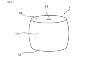
- FIG. 1 is a perspective view of an expanded bead.
- FIG. 2 is a cross-sectional view of the expanded bead of FIG. 1 taken along a cross section passing through the central axis of the expanded bead.
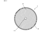
- FIG. 3 is a cross-sectional view taken along line III-III in FIG.
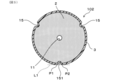
- FIG. 4 is a perspective view showing an example of an expanded bead having a groove on its side peripheral surface.
- FIG. 5 is a cross-sectional view taken along line VV in FIG.
- FIG. 6 is an explanatory diagram showing a method for calculating the area of the high-temperature peak.
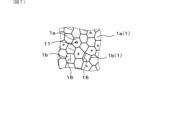
- FIG. 7 is a plan view showing a schematic view of the surface of the molded body.
- FIG. 8 is a photograph showing the appearance of the expanded bead molding of Example 1.
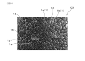
- FIG. 9 is a photograph showing the appearance of the expanded bead molding of Comparative Example 3.
- the expanded polypropylene resin bead 1 (hereinafter, also referred to as “expanded bead 1" or simply “expanded bead”) has a cylindrical shape with a through hole 11 penetrating the inside in the axial direction. More specifically, the expanded bead 1 has a bottom surface 12, a top surface 13 disposed above the bottom surface 12 and having a shape generally identical to that of the bottom surface 12, and a side peripheral surface 14 connecting the edge of the bottom surface 12 and the edge of the top surface 13. As shown in FIG. 2, the through hole 11 penetrates the inside of the expanded bead 1 in the axial direction and opens to the bottom surface 12 and the top surface 13.
- the aforementioned cylindrical shape includes, for example, a cylinder or a square tube as shown in FIG. 1.
- the number of through holes 11 provided in the expanded bead 1 may be one or more.
- the expanded beads 1 have an expanded core layer 2 made of a polypropylene resin and a coating layer 3 made of a polyolefin resin and coating the side surface of the expanded core layer 2.
- the coating layer 3 is provided on the outer surface of the expanded beads.
- the expanded core layer 2 and the coating layer 3 contain a coloring pigment.
- the melt mass-flow rate MFR S of the polyolefin resin constituting the coating layer is higher than 15 g/10 min.
- the formation of a streaky pattern on the surface of a polypropylene resin expanded bead molding (hereinafter also referred to as a "molded body").
- a polyolefin resin having a high melt mass-flow rate MFR S for the coating layer, the formation of a streaky pattern on the surface of the molded body can be suppressed without impairing the rigidity of the expanded core layer. Therefore, by using the expanded beads, the formation of a streaky pattern can be suppressed while maintaining the rigidity of the molded body.
- the average pore diameter d of the through holes in the expanded beads is less than 1 mm.
- the average pore diameter d of the through holes is more preferably 0.95 mm or less, further preferably 0.92 mm or less, and more preferably 0.
- the thickness is 0.90 mm or less, and most preferably 0.85 mm or less.
- curing step refers to a step of curing a molded product released from a mold during the manufacturing process of the molded product at 60°C. This refers to a process in which the mixture is left to stand for a predetermined period of time in a high-temperature atmosphere adjusted to a temperature of about 100 to 80°C.
- the average pore diameter d of the through holes is too large, it may take an excessively long time to dry the molded body. In addition, there is a risk that gaps between the foamed particles and irregularities caused by the through holes may easily form on the surface of the molded body, and the rigidity of the molded body may decrease.
- the average diameter d of the through holes is preferably 0.1 mm or more.
- the through holes of the foamed beads are prevented from being crushed and blocked during molding in the mold, and the effect of the through holes can be more reliably exerted.
- the average diameter d of the through holes is more preferably 0.2 mm or more, even more preferably 0.3 mm or more, particularly preferably 0.4 mm or more, and most preferably 0.5 mm or more.
- the upper and lower limits of the average pore diameter d of the through holes described above can be combined in any way.
- the preferred range of the average pore diameter d of the through holes may be, for example, 0.1 mm or more and less than 1 mm, 0.2 mm or more and 0.95 mm or less, 0.3 mm or more and 0.92 mm or less, 0.4 mm or more and 0.90 mm or less, or 0.5 mm or more and 0.85 mm or less.
- the open-cell structure is formed by a complex connection of voids formed when the through holes of multiple foamed beads are connected to each other, voids formed when the through holes of the foamed beads are connected to the gaps between the foamed beads, voids formed when the gaps between the foamed beads are connected, and open-cell parts of the foamed beads that make up the molded body.
- the open cell structure is connected to the outside of the molded body, it is believed that when a molded body with an appropriate open cell ratio is released from the mold, outside air will quickly flow through the open cell structure to the bubbles inside the molded body. And as outside air flows into the bubbles inside the molded body, the internal pressure of the entire molded body tends to quickly balance with the atmospheric pressure outside the molded body. As a result of the above, it is believed that the dimensions of the molded body tend to stabilize early, and significant shrinkage and deformation of the molded body can be suppressed even if a curing process is not performed.
- the expanded beads have through holes, it is believed that when steam is supplied into the mold, the steam can pass through the through holes. This makes it easier for the steam to reach the inside of the mold, and it is believed that the entire expanded beads in the mold can be easily heated. Therefore, even under low molding temperatures during in-mold molding, a molded body with excellent fusion properties and a good appearance can be obtained. As a result, the amount of heat that the expanded beads receive from the steam during in-mold molding can be kept low. In addition, the internal temperature of the molded body after release from the mold is prevented from becoming excessively high. As a result of these, it is believed that the dimensions of the molded body after in-mold molding can be stabilized more easily early.
- the molding temperature is likely to be high and it may be difficult to form a sufficient open cell structure in the resulting molded body. Therefore, in this case, it is difficult to prevent significant shrinkage, deformation, etc. of the molded body when the curing process is omitted. Also, in this case, the secondary foaming property of the expanded beads may become excessively high, and the cooling time in the mold may become long.
- the average pore diameter d of the through holes of the expanded beads is determined as follows. First, the expanded bead is cut in a plane perpendicular to the axial direction at the position where its cross-sectional area is maximum, exposing the cut surface as shown in Figure 3. Next, a photograph of the cut surface is taken, and the cross-sectional area (specifically, the opening area) of the through holes 11 in the cut surface is calculated. Then, the diameter of an imaginary perfect circle having the same area as the cross-sectional area of the through holes 11 is calculated, and this value is taken as the pore diameter of the through holes of each expanded bead. Note that in this specification, the position where the cross-sectional area of the expanded bead is maximum can be identified, for example, by 3D scanning the external shape of the expanded bead.
- the above operation is performed for 50 or more expanded beads 1, and the arithmetic mean value of the diameters of the through holes 11 in these expanded beads 1 is defined as the average diameter d of the through holes. Even if the cross-sectional area of the through holes 11 of each expanded bead 1 is not uniform in the axial direction, the average diameter d of the through holes of the expanded beads is determined using the diameter of the through holes 11 in the cut surface where the cross-sectional area of the expanded beads 1 is maximum, as described above.
- the average pore diameter d of the through holes can be adjusted to the above-mentioned specific range by adjusting the average pore diameter dr of the through holes in the multilayer resin particles described below and the bulk density of the expanded beads.
- the average pore diameter d can be more easily adjusted to a smaller value.
- the average circularity Cp of the through holes in a cross section obtained by cutting the expanded beads at a position where the cross-sectional area is maximum along a plane perpendicular to the axial direction is preferably 0.90 or more, more preferably 0.92 or more, and even more preferably 0.95 or more.
- the effect of improving the moldability of the expanded beads and the effect of shortening the cooling time during molding can be more easily obtained.
- the through holes are less likely to be crushed by external forces.
- the through holes are less likely to be blocked, and the moldability during in-mold molding can be further improved. Furthermore, by performing in-mold molding using the expanded beads, a molded body having excellent rigidity can be more easily obtained.
- the above operation is carried out for 50 or more randomly selected expanded beads 1, and the arithmetic mean value of the circularity of the through holes 11 in these expanded beads 1 is taken as the average circularity Cp of the through holes. Note that even if the cross-sectional shape of the through holes 11 of each expanded bead 1 is not uniform in the axial direction, the average circularity Cp of the through holes is determined based on the cross-sectional shape of the through holes at the position where the area of the cut surface of the expanded bead 1 is maximum, as described above.
- the average circularity Cp of the through holes can be adjusted to the above range, for example, by changing the shape of the die for forming the through holes in the granulation process of the multilayer resin particles described below, or by adjusting the water temperature when cooling the strands, which is usually about 25°C, to a lower water temperature (for example, 15°C or lower).
- the upper limit of the average circularity Cp of the through holes is 1.
- the preferred range of the average circularity Cp of the through holes may be, for example, 0.90 or more and 1 or less, 0.92 or more and 1 or less, or 0.95 or more and 1 or less.
- the ratio d/D of the average hole diameter d of the through holes to the average outer diameter D of the expanded beads is 0.4 or less.
- the ratio d/D of the average hole diameter d of the through holes to the average outer diameter D of the expanded beads is preferably 0.35 or less, more preferably 0.3 or less, and even more preferably 0.25 or less. If the ratio d/D is too high, the secondary expandability of the expanded beads during in-mold molding may decrease, leading to a decrease in the surface properties and rigidity of the molded body.
- the ratio d/D of the average pore size d of the through holes to the average outer diameter D of the expanded beads is 0.1 or more.
- the through holes of the expanded beads are less likely to be crushed even when an external force is applied, so that the effect of the through holes can be more reliably exerted.
- the preferable range of the ratio d/D of the average pore size d of the through holes to the average outer diameter D of the expanded beads may be, for example, 0.1 or more and 0.4 or less, 0.1 or more and 0.35 or less, 0.1 or more and 0.3 or less, or 0.1 or more and 0.25 or less.
- the average outer diameter D of the foamed beads is preferably 2 mm or more, more preferably 2.5 mm or more, and even more preferably 3 mm or more.
- the average outer diameter D of the foamed beads is preferably 8 mm or less, more preferably 5 mm or less, and even more preferably 4.5 mm or less.
- the upper and lower limits of the average outer diameter D of the expanded beads described above can be combined in any way.
- the preferred range of the average outer diameter D of the expanded beads may be, for example, 2 mm or more and 8 mm or less, 2.5 mm or more and 5 mm or less, or 3 mm or more and 4.5 mm or less.
- the method for calculating the average outer diameter D of the expanded beads described above is as follows. First, the expanded bead 1 is cut in a plane perpendicular to the axial direction at the position where its cross-sectional area is maximum, exposing the cut surface of the expanded bead 1 as shown in Figure 3. The cross-sectional area of the expanded bead 1, including the through holes 11, in this cut surface (i.e., the area of the region surrounded by the outer edge of the expanded bead 1 in the cut surface) is calculated. Then, the diameter of an imaginary perfect circle whose area is equal to the cross-sectional area of the expanded bead 1 is determined as the outer diameter of each expanded bead 1.
- the outer diameters of 50 or more expanded beads 1 are calculated, and the arithmetic mean value of the outer diameters of these expanded beads 1 is taken as the average outer diameter D of the expanded beads. Even if the cross-sectional area of each expanded bead 1 is not uniform in the axial direction, the average outer diameter D of the expanded beads is determined based on the cross-sectional area of the expanded beads 1 at the cut surface where the cross-sectional area of the expanded beads 1 is maximum, as described above.
- the average circularity Cb of the outer peripheral edge of the expanded beads in a cross section obtained by cutting the expanded beads at a position where the cross-sectional area is maximum along a plane perpendicular to the axial direction is preferably 0.95 or more, more preferably 0.96 or more.
- the average circularity Cb of the outer peripheral edge of the expanded beads is obtained as follows. First, the expanded beads are cut at the position where the cross-sectional area is maximum along a plane perpendicular to the axial direction to expose the cut surface as shown in FIG. 3. Next, a photograph of the cut surface of the expanded beads 1 is taken, and the cross-sectional area Sb of the expanded beads 1 including the through holes 11 (i.e., the area of the region surrounded by the outer peripheral edge of the expanded beads 1 on the cut surface) and the circumferential length Lb of the outer peripheral edge of the expanded beads 1 (i.e., the length of the outer peripheral edge of the expanded beads 1 on the cut surface) are measured.
- the cross-sectional area Sb of the expanded beads 1 including the through holes 11 i.e., the area of the region surrounded by the outer peripheral edge of the expanded beads 1 on the cut surface
- the circumferential length Lb of the outer peripheral edge of the expanded beads 1 i.e., the length of the outer peripheral edge of the expanded beads
- the above operation is carried out for 50 or more randomly selected expanded beads 1, and the arithmetic mean value of the circularity of these expanded beads 1 is taken as the average circularity Cb of the outer peripheral edge of the expanded beads.
- the average circularity Cb of the outer peripheral edge of the expanded beads is determined based on the cross-sectional shape of the expanded beads 1 at the cut surface where the cross-sectional area of the expanded beads 1 is maximum, as described above.
- the upper limit of the average circularity Cb of the outer peripheral edge is 1.
- the preferred range of the average circularity Cb of the outer peripheral edge of the expanded beads may be 0.95 or more and 1 or less, or 0.96 or more and 1 or less.
- the ratio Cb/Cp of the average circularity Cb of the outer periphery of the expanded beads to the average circularity Cp of the through holes of the expanded beads is preferably 0.96 or more and 1.05 or less, and more preferably 0.98 or more and 1.02 or less. In this case, it is possible to obtain a molded body with excellent rigidity while more reliably exerting the moldability improvement effect of the through holes, and it is possible to more effectively suppress the formation of streaky patterns on the surface of the molded body.
- of the difference between the average circularity Cb of the outer periphery of the expanded beads and the average circularity Cp of the through holes is preferably 0.03 or less, more preferably 0.01 or less, and even more preferably 0.008 or less.
- the average circularity Cb of the outer periphery of the expanded beads can be adjusted to fall within the above-mentioned specific range, for example, by forming the coating layer from a polyolefin resin having a melt mass-flow rate MFR S within the above-mentioned specific range.
- the ratio of the total cross-sectional area of the grooves to the cross-sectional area of the expanded beads excluding the through holes in a cross section obtained by cutting the expanded beads along a plane perpendicular to the axial direction at the position where the cross-sectional area is maximum is preferably 3% or less, more preferably 1.5% or less, even more preferably 1.2% or less, even more preferably 1% or less, particularly preferably 0.5% or less, and most preferably 0%, i.e., the expanded beads have no grooves on their side peripheral surfaces.
- the expanded bead 102 shown in FIG. 4 has a cylindrical shape surrounded by a bottom surface 12, a top surface 13, and a side surface 14, and has a through hole 11 passing through its interior in the axial direction.
- Three grooves 15 are formed on the side surface 14 of the expanded bead 102, positioned at approximately equal intervals in the circumferential direction of the expanded bead 102.
- the method for calculating the area ratio of the total cross-sectional area of the grooves in the expanded beads is as follows. First, the expanded beads 102 are cut in a plane perpendicular to the axial direction at the position where the cross-sectional area is maximum, exposing the cut surface as shown in Figure 5. Next, a photograph of the cut surface of the expanded beads 102 is taken, and the cross-sectional area of the expanded beads 102 excluding the through holes 11 (i.e., the area of the region enclosed by the outer peripheral edge and the inner peripheral edge of the expanded beads 102 on the cut surface) is measured.
- the through holes 11 i.e., the area of the region enclosed by the outer peripheral edge and the inner peripheral edge of the expanded beads 102 on the cut surface
- a tangent line L1 is drawn around each groove 15 in the photograph of the cut surface of the expanded bead 102, tangent to the contour of the expanded bead 102 at two points P1 and P2, and does not pass through the interior of the expanded bead 102.
- the area of the region enclosed by the contour of the expanded bead 102 and the tangent line L1 is then calculated, and this area is taken as the cross-sectional area of each groove 15.
- the cross-sectional area of each groove 15 is the area of the region 151 shown by the diagonal lines in Figure 5.
- the above operation is carried out for all grooves 15, and these are summed up to calculate the total cross-sectional area of the grooves 15 in each expanded bead 102.
- the total cross-sectional area of the grooves 15 thus obtained is divided by the cross-sectional area of the expanded beads 102 excluding the aforementioned through holes 11 to calculate the ratio of the total cross-sectional area of the grooves 15 to the cross-sectional area of the expanded beads 102 for each expanded bead 102.
- the above operation is carried out for 100 or more expanded beads 102, and the arithmetic mean value of the ratios for these expanded beads 102 is taken as the area ratio of the total cross-sectional area of the grooves in the expanded beads.
- the coating layer By forming the coating layer from a polyolefin resin having a melt mass-flow rate MFR S within the above-mentioned specific range, the formation of grooves on the circumferential side surface of the expanded beads can be suppressed, and the area ratio of the total cross-sectional area of the grooves in the expanded beads can be easily adjusted to within the above-mentioned range.
- the reason for this is not necessarily clear, but it is thought that the residual stress remaining in the resin particles obtained in the granulation step described below is alleviated, making it difficult for wrinkles to form in the expanded beads, and that the coating layer is more easily formed uniformly on the circumferential side surface of the obtained expanded beads.
- the average wall thickness t of the expanded beads is preferably 1.2 mm or more and 2 mm or less.
- the secondary expandability of the expanded beads during in-mold molding can be further improved.
- the expanded beads having an average wall thickness t within the specific range are less likely to be crushed by external forces, so that the rigidity of the molded body obtained by in-mold molding of the expanded beads can be further improved.
- the average wall thickness t of the expanded beads is more preferably 1.3 mm or more and 2 mm or less, and even more preferably 1.5 mm or more and 2 mm or less.
- the apparent density of the expanded beads is preferably 10 kg/m 3 or more and 100 kg/m 3 or less, more preferably 20 kg/m 3 or more and 80 kg/m 3 or less, even more preferably 25 kg/m 3 or more and 60 kg/m 3 or less, and particularly preferably 30 kg/m 3 or more and 50 kg/m 3 or less.
- a lightweight molded body having excellent rigidity can be easily obtained.
- the expanded beads can omit the curing step even when the apparent density is low, so that a lightweight molded body having a desired shape can be produced without curing.
- the method for calculating the apparent density of expanded beads is as follows. First, the expanded beads are left to stand for one day in an environment of 50% relative humidity, 23°C temperature, and 1 atm pressure to adjust the state of the expanded beads. After measuring the mass (unit: g) of the expanded beads, the expanded beads are submerged in a measuring cylinder containing alcohol (e.g., ethanol) at 23°C using a wire net or the like, and the volume (unit: L) of the expanded beads is calculated from the rise in the liquid level. The mass of the expanded beads is then divided by the volume of the expanded beads to convert the value into units, thereby calculating the apparent density (unit: kg/ m3 ) of the expanded beads.
- alcohol e.g., ethanol
- the foamed core layer of the foamed beads is composed of a polypropylene-based resin.
- the polypropylene-based resin refers to a homopolymer of a propylene monomer and a propylene-based copolymer containing 50% by mass or more of a structural unit derived from propylene.
- the foamed core layer may contain one type of polypropylene-based resin or two or more types of polypropylene-based resins.
- the foamed core layer is more preferably composed of a propylene-based copolymer in which propylene is copolymerized with another monomer.
- propylene-based copolymers include copolymers of propylene and an ⁇ -olefin having 4 to 10 carbon atoms, such as ethylene-propylene copolymer, butene-propylene copolymer, hexene-propylene copolymer, and ethylene-propylene-butene copolymer. These copolymers may be, for example, random copolymers or block copolymers, but are preferably random copolymers.
- the melting point Tmc of the polypropylene resin constituting the foamed core layer is preferably 155°C or less.
- a molded body having excellent appearance and rigidity can be molded at a lower molding temperature (i.e., low molding pressure).
- the melting point Tmc of the polypropylene resin constituting the foamed core layer is preferably 152°C or less, and more preferably 148°C or less.
- the melting point Tmc of the polypropylene resin constituting the foamed core layer is preferably 135°C or more, more preferably 138°C or more, and even more preferably 140°C or more.
- the preferred range of the melting point Tmc of the polypropylene resin constituting the foamed core layer may be, for example, 135°C or more and 155°C or less, 138°C or more and 152°C or less, or 140°C or more and 148°C or less.
- the melting point Tmc of the polypropylene resin constituting the foamed core layer can be determined based on the DSC curve obtained by performing differential scanning calorimetry (DSC) based on JIS K7121-1987. Specifically, a test piece made of polypropylene resin is prepared, and the condition of the test piece is adjusted according to "(2) Measurement of melting temperature after a certain heat treatment". The heating and cooling rates in the condition adjustment are 10°C/min, and the temperature range is from 30°C to 200°C. The test piece thus adjusted is heated from 30°C to 200°C at a heating rate of 10°C/min to obtain a DSC curve.
- the apex temperature of the melting peak that appears on the DSC curve is the melting point Tmc of the polypropylene resin. Note that if multiple melting peaks appear on the DSC curve, the apex temperature of the melting peak with the largest area is the melting point Tmc.
- the melt mass-flow rate MFR C of the polypropylene-based resin constituting the foamed core layer is preferably 5 g/10 min or more, more preferably 6 g/10 min or more, and even more preferably 7 g/10 min or more. In this case, the foamability and moldability can be further improved.
- the melt mass-flow rate MFR C of the polypropylene-based resin constituting the foamed core layer is preferably 12 g/10 min or less, and more preferably 10 g/10 min or less.
- the upper and lower limits of the melt mass flow rate MFR C described above can be combined arbitrarily.
- the preferred range of the melt mass flow rate MFR C of the polypropylene resin constituting the foamed core layer may be 5 g/10 min or more and 12 g/10 min or less, 6 g/10 min or more and 12 g/10 min or less, or 7 g/10 min or more and 10 g/10 min or less.
- the MFR C of the polypropylene resin constituting the foamed core layer is a value measured based on JIS K7210-1:2014 under the conditions of a test temperature of 230° C. and a load of 2.16 kg.
- the foamed beads can suppress the formation of streaky patterns on the surface of the molded article by covering the side peripheral surface of the foamed core layer with a covering layer made of a polyolefin resin having a high melt mass-flow rate MFR S.
- a polyolefin resin having a high melt mass-flow rate MFR S can be used as the resin constituting the covering layer
- a polypropylene resin having a relatively low melt mass-flow rate MFR C for example, within the above range, can be used as the resin constituting the foamed core layer.
- the foamed core layer may contain polymers other than polypropylene-based resins, provided that the above-mentioned effects are not impaired.
- polymers include thermoplastic resins other than polypropylene-based resins, such as polyethylene-based resins and polystyrene-based resins, and thermoplastic elastomers.
- the content of polymers other than polypropylene-based resins in the foamed core layer is preferably 20% by mass or less, more preferably 10% by mass or less, even more preferably 5% by mass or less, and particularly preferably 0, i.e., the foamed core layer contains substantially only polypropylene-based resins as polymers.
- the foamed core layer may also contain additives such as bubble regulators, crystal nucleating agents, flame retardants, flame retardant assistants, plasticizers, antistatic agents, antioxidants, UV inhibitors, light stabilizers, conductive fillers, and antibacterial agents, so long as the additives do not impair the aforementioned effects.
- additives such as bubble regulators, crystal nucleating agents, flame retardants, flame retardant assistants, plasticizers, antistatic agents, antioxidants, UV inhibitors, light stabilizers, conductive fillers, and antibacterial agents, so long as the additives do not impair the aforementioned effects.
- the content of the additives in the foamed core layer is preferably, for example, 0.01 parts by mass or more and 10 parts by mass or less per 100 parts by mass of the polypropylene resin.
- the side surface of the foamed core layer in the expanded beads is covered with a coating layer made of a polyolefin resin.
- the coating layer of the expanded beads may be in a foamed state or a non-foamed state, but is preferably in a substantially non-foamed state.
- non-foamed state includes a state in which the coating layer is not foamed and does not contain bubbles, and a state in which bubbles have disappeared after foaming, and means that there is almost no bubble structure in the coating layer.
- "A to B" representing a numerical range is synonymous with "A or more and B or less” and represents a numerical range including the endpoints A and B of the numerical range.
- the polyolefin resin constituting the coating layer may be, for example, a polyethylene resin, a polypropylene resin, or a polybutene resin. From the viewpoint of adhesion to the foamed core layer, the polyolefin resin constituting the coating layer is preferably a polyethylene resin or a polypropylene resin, and more preferably a polypropylene resin.
- the polypropylene resin constituting the coating layer may be, for example, an ethylene-propylene copolymer, a butene-propylene copolymer, an ethylene-propylene-butene copolymer, or a propylene homopolymer.
- the polypropylene resin constituting the coating layer is preferably an ethylene-propylene copolymer or an ethylene-propylene-butene copolymer.
- the polyethylene resin constituting the coating layer may be, for example, a linear low-density polyethylene (PE-LLD), a low-density polyethylene (PE-LD), a medium-density polyethylene (PE-MD), or a high-density polyethylene (PE-HD).
- the polyolefin resin constituting the coating layer has a melt mass-flow rate MFR S higher than 15 g/10 min.
- MFR S melt mass-flow rate of the polyolefin resin constituting the coating layer
- MFR C melt mass-flow rate of the polypropylene resin constituting the foamed core layer
- the difference MFR -MFR between the melt mass-flow rate MFR of the polyolefin resin constituting the coating layer and the melt mass-flow rate MFR of the polypropylene resin constituting the foamed core layer is preferably 10 g/10 min or more, and more preferably 12 g/10 min or more.
- the ratio MFR / MFR of the melt mass-flow rate MFR of the polyolefin resin constituting the coating layer to the melt mass-flow rate MFR of the polypropylene resin constituting the foamed core layer is preferably 2 or more, and more preferably 2.5 or more.
- the difference MFR -MFR between the melt mass-flow rate MFR of the polyolefin resin constituting the coating layer and the melt mass-flow rate MFR of the polypropylene resin constituting the foamed core layer is preferably 30 g/10 min or less.
- the ratio MFR / MFR of the melt mass-flow rate MFR of the polyolefin resin constituting the coating layer to the melt mass-flow rate MFR of the polypropylene resin constituting the foamed core layer is preferably 5 or less, and more preferably 4 or less.
- the upper and lower limits of the difference MFR S -MFR C described above can be combined arbitrarily.
- the preferred range of the difference MFR S -MFR C may be 10 g/10 min or more and 30 g/10 min or less, or 12 g/10 min or more and 30 g/10 min or less.
- the upper and lower limits of the ratio MFR S /MFR C described above can be combined arbitrarily.
- the ratio MFR S /MFR C may be preferably in the range of 2 or more and 5 or less, or 2.5 or more and 4 or less.
- the MFR of the polyolefin resin constituting the coating layer is a value measured under conditions of a test temperature of 230° C. and a load of 2.16 kg based on JIS K7210-1: 2014. Even when the coating layer is made of a polyethylene resin, the MFR is measured under conditions of a test temperature of 230° C. and a load of 2.16 kg.
- the melting point Tms of the polyolefin resin constituting the coating layer is preferably lower than the melting point Tmc of the polypropylene resin constituting the foamed core layer.
- the difference Tmc-Tms between the melting point Tmc of the polypropylene resin constituting the foamed core layer and the melting point Tms of the polyolefin resin constituting the coating layer is preferably more than 0°C and less than 40°C, more preferably 3°C to 35°C, and even more preferably 5°C to 30°C.
- the method for measuring the melting point Tms of the polyolefin resin that constitutes the coating layer is the same as the method for measuring the melting point Tmc of the polypropylene resin that constitutes the foamed core layer described above, except that a polyolefin resin is used instead of a polypropylene resin.
- the coating layer may contain additives such as crystal nucleating agents, flame retardants, flame retardant assistants, plasticizers, antistatic agents, antioxidants, UV inhibitors, light stabilizers, conductive fillers, and antibacterial agents, so long as they do not impair the aforementioned effects.
- the content of the additives in the coating layer is preferably, for example, 0.01 parts by mass or more and 10 parts by mass or less per 100 parts by mass of the polyolefin resin.
- the foam core layer and the coating layer contain a coloring pigment.
- the coloring pigment may be any color other than white, and may be any color having various tones, such as black, red, blue, yellow, and green pigments.
- the coloring pigment may be an inorganic pigment or an organic pigment.
- Inorganic pigments include, for example, carbon particles such as carbon black; chromates such as yellow lead, zinc yellow, and barium yellow; ferrocyanides such as Prussian blue; sulfides such as cadmium yellow and cadmium red; oxides such as red iron oxide; and silicates such as ultramarine.
- Organic pigments include, for example, azo pigments such as monoazo pigments, disazo pigments, azo lakes, condensed azo pigments, and chelate azo pigments; and polycyclic pigments such as phthalocyanines, anthraquinones, perylenes, perinones, thioindigo, quinacridones, dioxazines, isoindolinones, and quinophthalones.
- the foam core layer may contain one type of color pigment or may contain two or more types of color pigments.
- the coating layer may contain one type of color pigment or may contain two or more types of color pigments.
- the color tone of the color pigment in the foam core layer and the color pigment in the coating layer may be the same or different. From the viewpoint of imparting a luxurious feel to the molded article, it is preferable that the color pigment in the foam core layer and the coating layer is a black pigment. It is preferable to use carbon particles as the black pigment, and more specifically, it is preferable to use carbon black.
- the content of the color pigment in the foamed core layer is 0.1% by mass or more and 5% by mass or less, and the content of the color pigment in the coating layer is 0.1% by mass or more and 5% by mass or less.
- the desired color tone can be imparted to the foamed particles while sufficiently ensuring the secondary foaming and fusion properties of the foamed particles during molding in the mold. This makes it easier to obtain a molded body having a desired color tone and good appearance.
- the content of the color pigment in the foamed core layer is 0.3% by mass or more and 4.5% by mass or less
- the content of the color pigment in the coating layer is 0.3% by mass or more and 4.5% by mass or less
- the content of the color pigment in the foamed core layer is 0.5% by mass or more and 4% by mass or less
- the content of the color pigment in the coating layer is 0.5% by mass or more and 4% by mass or less.
- the reason why the streaky pattern is formed on the surface of the molded body is thought to be, for example, that the grooves formed on the side peripheral surface of the expanded beads described above are exposed on the surface of the molded body.
- Such streaky patterns on the surface of the molded body are particularly noticeable in molded bodies made by molding expanded beads containing color pigments. This is thought to be because the streaky pattern often appears lighter in color than the surrounding area and is less noticeable in white molded bodies that do not contain color pigments, and because, in the past, the average circularity of the outer peripheral edge of expanded beads containing color pigments was particularly likely to be low.
- the expanded beads prevent the deterioration of the appearance caused by the streaky pattern even in colored molded bodies obtained from expanded beads containing color pigments.
- the closed cell ratio of the expanded beads is preferably 90% or more, more preferably 92% or more, and even more preferably 95% or more.
- the closed cell ratio of the expanded beads can be measured using an air comparison type specific gravity meter based on ASTM-D2856-70 procedure C. Specifically, it is measured as follows. First, the expanded beads are left to stand for 24 hours or more in an environment of 50% relative humidity, 23°C temperature, and 1 atm pressure to condition the expanded beads. A measurement sample is taken from the expanded beads after the condition adjustment so that the value of the mark line when naturally deposited in a graduated cylinder is about 20 cm3 . This measurement sample is submerged in a graduated cylinder containing ethanol at a temperature of 23°C, and the apparent volume of the measurement sample is measured based on the amount of rise in the liquid level.
- Vx (unit: cm3 ) is the true volume of the expanded bead (i.e., the sum of the volume of the resin that constitutes the expanded bead and the total volume of the air bubbles in the closed cell portion within the expanded bead)
- Va (unit: cm3 ) is the apparent volume of the expanded bead (i.e., the volume measured from the rise in the liquid level when the expanded bead is submerged in a measuring cylinder containing ethanol)
- W (unit: g) is the mass of the measurement sample
- ⁇ (unit: g/ cm3 ) is the density of the polypropylene resin that constitutes the foamed core layer.
- the above procedure is carried out five times using different measurement samples, and the arithmetic mean value of the closed cell ratio obtained from these five measurements is regarded as the closed cell ratio of the expanded particles.
- the expanded beads preferably have a crystal structure in which an endothermic peak due to melting inherent to the polypropylene resin constituting the expanded core layer and one or more melting peaks located on the higher temperature side than the endothermic peak appear in the DSC curve obtained when the expanded beads are heated from 23°C to 200°C at a heating rate of 10°C/min. Expanded beads having such a crystal structure are excellent in mechanical strength and moldability.
- the endothermic peak due to melting inherent to the polypropylene resin constituting the expanded core layer is referred to as the "resin-specific peak”
- the melting peak appearing on the higher temperature side than the resin-specific peak is referred to as the "high-temperature peak”.
- the resin-specific peak is generated by endothermic heat generated when the crystals inherent to the polypropylene resin constituting the expanded core layer melt.
- the high-temperature peak is presumed to be generated by melting of secondary crystals formed in the polypropylene resin constituting the expanded core layer during the manufacturing process of the expanded beads. That is, when a high-temperature peak appears in the DSC curve, it is presumed that secondary crystals are formed in the polypropylene resin.
- Whether or not the expanded particles have the above-mentioned crystal structure can be determined based on the DSC curve obtained by performing differential scanning calorimetry (DSC) under the above-mentioned conditions in accordance with JIS K7121:1987.
- DSC differential scanning calorimetry
- 1 to 3 mg of expanded particles can be used as a sample.
- the DSC curve obtained shows both a high-temperature peak and a resin peak specific to the polypropylene resin constituting the foamed core layer.
- the material is cooled from 200°C to 23°C at a cooling rate of 10°C/min, and then heated again from 23°C to 200°C at a heating rate of 10°C/min (i.e., the second heating)
- the DSC curve obtained shows only the resin peak specific to the polypropylene resin constituting the foamed core layer.
- the resin peak and the high-temperature peak can be distinguished.
- the temperature at the apex of this resin peak may differ slightly between the first heating and the second heating, but the difference is usually within 5°C.
- the heat of fusion of the high-temperature peak of the expanded beads is preferably 5 J/g or more and 40 J/g or less, more preferably 7 J/g or more and 30 J/g or less, and even more preferably 10 J/g or more and 20 J/g or less, from the viewpoint of further improving the moldability of the expanded beads and obtaining a molded body with superior rigidity.
- the heat of fusion of the high-temperature peak mentioned above is a value that can be determined as follows. First, the expanded beads are allowed to stand for 24 hours under conditions of 50% relative humidity, 23°C, and 1 atm to adjust the state of the expanded beads. After the adjustment, 1 to 3 mg of the expanded beads are used as a sample, and a DSC curve is obtained by performing differential scanning calorimetry under conditions of heating from 23°C to 200°C at a heating rate of 10°C/min. Figure 6 shows an example of a DSC curve.
- the DSC curve will show a resin-specific peak ⁇ H1 and a high-temperature peak ⁇ H2 that has its apex on the higher temperature side than the apex of the resin-specific peak ⁇ H1, as shown in Figure 6.
- the end temperature T of melting is the high temperature end point of the high temperature peak ⁇ H2, that is, the intersection point of the high temperature peak ⁇ H2 and the baseline on the higher temperature side of the high temperature peak ⁇ H2 on the DSC curve.
- draw line L3 parallel to the vertical axis of the graph, passing through the maximum point ⁇ that exists between the resin-specific peak ⁇ H1 and the high-temperature peak ⁇ H2. This line L3 divides the resin-specific peak ⁇ H1 and the high-temperature peak ⁇ H2.
- the heat absorption amount of the high-temperature peak ⁇ H2 can be calculated based on the area of the part of the DSC curve that constitutes the high-temperature peak ⁇ H2 and the part surrounded by lines L2 and L3.
- the method for producing the expanded beads includes a granulation step for producing multilayer resin beads having a cylindrical core layer made of a polypropylene resin and having a through hole, and a coating layer made of a polyolefin resin and coating the lateral surface of the core layer, and an expansion step for expanding the multilayer resin beads. Each step will be described in more detail below.
- the method for producing the multilayer resin particles in the granulation step is not particularly limited, but for example, the multilayer resin particles can be produced by the strand cut method.
- the multilayer resin particles are produced using a co-extrusion device equipped with an extruder for forming a core layer, an extruder for forming a coating layer, and a co-extrusion die connected to these two extruders.
- the polypropylene-based resin that will be the foamed core layer of the expanded beads, the coloring pigment, and additives that are added as necessary are fed to the extruder for forming the core layer, and these are melt-kneaded in the extruder for forming the core layer to produce a resin melt-kneaded product for forming the core layer.
- the polyolefin-based resin that will be the coating layer of the expanded beads, the coloring pigment, and additives that are added as necessary are fed to the extruder for forming the coating layer, and these are melt-kneaded in the extruder for forming the coating layer to produce a resin melt-kneaded product for forming the coating layer.
- the molten mixture is discharged from each extruder and merged in a co-extrusion die to form a multilayer composite consisting of a non-foamed core layer and a non-foamed coating layer that covers the side surface of the core layer.
- the composite is then extruded through small holes in a die equipped with a mechanism capable of forming through holes in the core layer to form a strand-shaped extrudate having through holes in the core layer.
- This extrudate is collected and cooled, and then cut to the desired length to obtain multilayer resin particles having through holes in the core layer.
- the method for producing multilayer resin particles is not limited to the above-mentioned method, and a hot cutting method, an underwater cutting method, etc. may also be used.
- the particle diameter, length/outer diameter ratio, and mass per particle of the multilayer resin particles can be adjusted by appropriately changing the extrusion speed, collection speed, cutter speed, etc. during extrusion of the resin molten mixture.
- the average outer diameter Dr of the multilayer resin particles is preferably 0.1 mm or more and 3.0 mm or less, and more preferably 0.3 mm or more and 1.5 mm or less.
- the mass of each multilayer resin particle is preferably 0.1 mg or more and 20 mg or less, more preferably 0.2 mg or more and 10 mg or less, even more preferably 0.3 mg or more and 5 mg or less, and particularly preferably 0.4 mg or more and 2 mg or less.
- the mass of each multilayer resin particle is the value obtained by dividing the mass of 200 randomly selected multilayer resin particles by the number of multilayer resin particles.
- the mass of each multilayer resin particle obtained by the above-mentioned method is sometimes referred to as the "average mass of multilayer resin particles.”
- the average pore size dr of the through holes in the core layer of the multilayer resin particles is set to less than 0.25 mm and setting the ratio dr/Dr of the average pore size dr of the through holes to the average outer diameter Dr of the multilayer resin particles to 0.4 or less, expanded beads having the above specific shape can be easily obtained.
- the average pore size dr of the through holes in the core layer of the multilayer resin particles and the ratio dr/Dr can be adjusted, for example, by the diameter of the small holes in the die used to form the through holes (i.e., the inner diameter of the die).
- the method for calculating the average outer diameter Dr of the multilayer resin particles and the average pore size dr of the through holes is the same as the method for calculating the average outer diameter D of the expanded beads and the average pore size d of the through holes described above, except that multilayer resin particles are used instead of expanded beads.
- the multilayer resin particles are foamed.
- the method for foaming the multilayer resin particles is not particularly limited, but it is preferable to employ, for example, a method called a "direct foaming method" in which the multilayer resin particles containing a foaming agent dispersed in an aqueous medium in a container are released together with the dispersion medium into an atmosphere having a pressure lower than that inside the container.
- the multilayer resin particles When expanding the multilayer resin particles by the direct expansion method, the multilayer resin particles are first placed in a container such as a pressure vessel and dispersed in a dispersion medium. At this time, if necessary, a dispersant, dispersion aid, surfactant, etc. may be added to disperse the multilayer resin particles in the dispersion medium in the container.
- an aqueous dispersion medium containing water as the main component is used.
- the aqueous dispersion medium may contain hydrophilic organic solvents such as ethylene glycol, glycerin, methanol, and ethanol.
- the proportion of water in the aqueous dispersion medium is preferably 60% by mass or more, more preferably 70% by mass or more, and even more preferably 80% by mass or more.
- a dispersant to the dispersion medium.
- a dispersant By adding a dispersant to the dispersion medium, it is possible to suppress fusion between the multilayer resin particles heated in the container during the foaming process.
- the amount of dispersant added is preferably 0.001 to 5 parts by mass per 100 parts by mass of the multilayer resin particles.
- organic dispersants and inorganic dispersants can be used, but it is preferable to use fine inorganic particles as the dispersant because of ease of handling.
- the dispersant for example, clay minerals such as amsnite, kaolin, mica, and clay, aluminum oxide, titanium oxide, basic magnesium carbonate, basic zinc carbonate, calcium carbonate, and iron oxide can be used. These dispersants may be used alone, or two or more types of dispersants may be used in combination. Among these, it is preferable to use a clay mineral as the dispersant.
- the clay mineral may be natural or synthetic.
- an anionic surfactant such as sodium dodecylbenzenesulfonate, sodium alkylbenzenesulfonate, sodium lauryl sulfate, or sodium oleate in combination as a dispersing aid.
- the amount of dispersing aid added is preferably 0.001 to 1 part by mass per 100 parts by mass of multilayer resin particles.
- the multilayer resin particles are impregnated with a blowing agent in a container.
- the blowing agent impregnated into the multilayer resin particles is preferably a physical blowing agent.
- physical blowing agents include inorganic physical blowing agents such as carbon dioxide, air, nitrogen, helium, and argon, and organic physical blowing agents such as aliphatic hydrocarbons such as propane, butane, and hexane, cyclic aliphatic hydrocarbons such as cyclopentane and cyclohexane, and halogenated hydrocarbons such as 1,3,3,3-tetrafluoropropene, 1-chloro-3,3,3-trifluoropropene, 1-chloro-2,3,3,3-tetrafluoropropene, chlorofluoromethane, trifluoromethane, 1,1-difluoromethane, 1-chloro-1,1-dichloroethane,
- these physical blowing agents may be used alone, or two or more types of physical blowing agents may be used in combination.
- inorganic physical blowing agents and organic physical blowing agents may be mixed and used.
- the physical foaming agent used is preferably an inorganic physical foaming agent, and more preferably carbon dioxide.
- the amount of foaming agent added per 100 parts by mass of multilayer resin particles is preferably 0.1 parts by mass or more and 30 parts by mass or less, and more preferably 0.5 parts by mass or more and 15 parts by mass or less.
- a method for impregnating the multilayer resin particles with a blowing agent for example, a method can be used in which the blowing agent is supplied into a container and the multilayer resin particles in the dispersion medium are impregnated with the blowing agent.
- the impregnation of the multilayer resin particles with the blowing agent can be further promoted by heating the multilayer resin particles together with the dispersion medium.
- the pressure inside the container during expansion is preferably 0.5 MPa (G) or more in gauge pressure.
- the pressure inside the container is preferably 4.0 MPa (G) or less in gauge pressure. If it is within the above range, expanded beads can be produced safely without risk of damage to the container or explosion, etc.
- the temperature of the dispersion medium can be increased at a rate of 1 to 5°C/min, so that the temperature during foaming can be kept within an appropriate range.
- the contents of the container are released into an environment with a lower pressure than the container. This causes the core layer of the multilayer resin particles to foam and form a bubble structure, which is then cooled by the outside air, stabilizing the bubble structure and yielding foamed particles.
- a one-stage holding step is performed in which a temperature is held at a temperature of (melting point of polypropylene resin -20°C) or more and less than (end of melting temperature of polypropylene resin) for a sufficient time, preferably about 10 to 60 minutes, and then the temperature is adjusted to (melting point of polypropylene resin -15°C) to less than (end of melting temperature of polypropylene resin +10°C). Then, if necessary, a two-stage holding step is performed in which the temperature is held for a further sufficient time, preferably about 10 to 60 minutes.
- the temperature inside the container is set to (melting point of polypropylene resin -10°C) or more, and foam the multilayer resin particles. It is more preferable that the temperature inside the container during foaming is (melting point of polypropylene resin) or more and (melting point of polypropylene resin +20°C) or less.
- the multilayer resin particles may be expanded in one stage by the direct expansion method described above, or the expanded particles obtained by the direct expansion method may be further expanded.
- the first stage expansion process is called the first stage expansion process
- the expanded particles obtained by the first stage expansion process are called first stage expanded particles.
- the second stage expansion process is called the second stage expansion process.
- the expanded particles obtained by the two stage expansion process are sometimes called second stage expanded particles.
- Specific methods for expanding multi-layer resin particles in two stages are, for example, as follows. First, in the first-stage expansion step, the multi-layer resin particles are expanded, for example, by the direct expansion method described above, to obtain first-stage expanded particles. Then, internal pressure is applied to the first-stage expanded particles. More specifically, the first-stage expanded particles are placed in a pressure-resistant container, and the container is pressurized with air or an inorganic gas such as carbon dioxide to impregnate the first-stage expanded particles with the inorganic gas. This makes the pressure inside the bubbles of the first-stage expanded particles equal to or higher than atmospheric pressure.
- the first-stage expanded particles are taken out of the pressure-resistant container and heated with a heating medium such as steam or heated air in an environment with a pressure lower than the pressure inside the bubbles, thereby causing the first-stage expanded particles to undergo second-stage expansion.
- a heating medium such as steam or heated air in an environment with a pressure lower than the pressure inside the bubbles
- the expanded beads can be molded in a mold to obtain an expanded bead molded article.
- the molded article has an open cell structure.
- the open cell structure is a minute space portion that communicates with the outside of the molded article.
- the open cell structure is formed by complex connections of voids formed by mutual communication between through holes of a plurality of expanded beads, voids formed by communication between through holes of the expanded beads and voids formed between the expanded beads, voids formed by communication between gaps between the expanded beads, and open cell portions of the expanded beads that constitute the molded article.
- the molded articles are also used as sound absorbing materials, shock absorbing materials, and cushioning materials in various fields such as the automotive and construction fields.
- the expanded beads are filled into a mold, and then steam is supplied into the mold as a heating medium to perform in-mold molding.
- the expanded beads are first filled into a mold having a cavity corresponding to the shape of the desired molded body. After filling with the expanded beads is complete, steam is supplied into the mold to heat the expanded beads.
- the expanded beads in the mold are heated by the steam and fuse together while undergoing secondary expansion. This allows the expanded beads in the mold to be integrated and form a molded body.
- a curing step may be performed in which the molded body after demolding is left to stand for a predetermined period of time in a high-temperature atmosphere adjusted to a temperature of, for example, about 60°C to 80°C.
- a curing step may be performed in which the molded body after demolding is left to stand for a predetermined period of time in a high-temperature atmosphere adjusted to a temperature of, for example, about 60°C to 80°C.
- the shape of the molded body can be stabilized, for example, by leaving the molded body after demolding in an environment of 23°C for 12 hours.
- the melting point of the resin was determined based on JIS K7121:1987. Specifically, first, the condition of the test piece made of the resin was adjusted based on "(2) A case where the melting temperature is measured after a certain heat treatment" described in JIS K7121:1987. The heating temperature and cooling temperature in the condition adjustment were 10°C/min, and the temperature range was 30°C to 200°C. The test piece after the condition adjustment was heated from 30°C to 200°C at a heating rate of 10°C/min to obtain a DSC curve. The apex temperature of the melting peak that appeared on the DSC curve was taken as the melting point. A heat flux differential scanning calorimeter (manufactured by SII Nanotechnology Co., Ltd., model number: DSC7020) was used as the measuring device.
- melt mass flow rates of the polypropylene-based resin and the polyethylene-based resin were measured in accordance with JIS K7210-1:2014 under conditions of a temperature of 230° C. and a load of 2.16 kg.
- the melt mass flow rate of the resin constituting the coating layer is represented as MFR S
- the melt mass flow rate of the resin constituting the foamed core layer is represented as MFR C.
- Example 1 1 to 3 the expanded bead 1 of Example 1 has a cylindrical shape and has a through hole 11 passing through the inside in the axial direction.
- the expanded bead 1 of Example 1 has a multilayer structure including an expanded core layer 2 made of PP1 and a non-expanded coating layer 3 made of PP3 that coats the expanded core layer 2.
- the method for producing the foamed particles in this example is as follows:
- the multi-layer resin particles were prepared by the strand cut method. Specifically, a co-extrusion device equipped with a core layer forming extruder, a coating layer forming extruder, and a co-extrusion die connected to these two extruders was used, and the extrudate extruded from the co-extrusion device was cut to an appropriate length to prepare the multi-layer resin particles. Specifically, in the core layer forming extruder, PP1, carbon black as a coloring pigment, and zinc borate as a bubble regulator were melt-kneaded to obtain a resin melt-kneaded product for forming the core layer.
- the amount of zinc borate was 500 ppm by mass relative to the mass of PP1, and the amount of carbon black in the resin melt for forming the core layer was 2.7% by mass in the resin melt for forming the core layer.
- PP3 and carbon black as a coloring pigment were melt-kneaded to obtain a resin melt-kneaded product for forming the coating layer.
- the amount of carbon black blended into the molten kneaded resin for forming the coating layer was 2.7% by mass in the molten kneaded resin for forming the coating layer.
- the multilayer resin particles were expanded in two stages to produce expanded particles.
- the multilayer resin particles were expanded by a direct expansion method to produce first-stage expanded particles. Specifically, 1 kg of the multilayer resin particles was first placed in a 5-L container together with 3 L of water as a dispersion medium. Next, 0.3 parts by mass of a dispersant and 0.004 parts by mass of a dispersion aid were added to the container relative to 100 parts by mass of the multilayer resin particles, and the multilayer resin particles were dispersed in the dispersion medium. Kaolin was used as the dispersant. A surfactant (specifically, sodium alkylbenzene sulfonate) was used as the dispersion aid.
- the container was sealed, and carbon dioxide was added to the container as a foaming agent.
- the container was then heated to the temperature shown in the "Foaming Temperature” column in Table 2 while stirring.
- the pressure inside the container also called the impregnation pressure or carbon dioxide pressure
- the container was opened and the contents were released under atmospheric pressure, thereby obtaining a first-stage expanded particle having a foamed core layer formed by the foaming of the core layer, and a non-foamed coating layer that covers the foamed core layer.
- the first-stage expanded particles were further expanded by carrying out a second-stage expansion process to obtain expanded particles.
- the first-stage expanded particles were placed in a pressure-resistant container (specifically, a metal drum), and air was supplied into the pressure-resistant container to increase the pressure inside the container and impregnate the air bubbles with air.
- the internal pressure of the air bubbles in the first-stage expanded particles removed from the pressure-resistant container was as shown in Table 2.
- the first-stage expanded particles were then placed in a metal drum, and steam was supplied to heat the first-stage expanded particles so that the drum pressure reached the value shown in Table 2, obtaining expanded particles having the apparent density shown in Table 2.
- Example 2 Except for the apparent density, the expanded beads of this example have a structure generally similar to that of the expanded beads of Example 1.
- the method for producing the expanded beads of this example is the same as that of Example 1, except that the drum pressure in the second-stage expansion step is changed as shown in Table 2.
- Example 3 The expanded beads of this example have a structure similar to that of the expanded beads of Example 1, except that the resin constituting the expanded core layer is changed from PP1 to PP2.
- the method for producing the expanded beads of this example is similar to the method for producing the expanded beads of Example 1, except that the resin fed into the extruder for forming the core layer in the granulation step is changed from PP1 to PP2 and the conditions of the expansion step are changed as shown in Table 2.
- Example 4 The expanded beads of this example have a structure similar to that of the expanded beads of Example 1, except that the resin constituting the coating layer is changed from PP3 to PE1.
- the method for producing the expanded beads of this example is similar to the method for producing the expanded beads of Example 1, except that the resin fed into the extruder for forming the coating layer in the granulation step is changed from PP3 to PE1.
- Example 5 The expanded beads of this example have a structure similar to that of the expanded beads of Example 1, except that the amount of carbon black blended in the resin melt-kneaded mixture for forming the core layer and the resin melt-kneaded mixture for forming the coating layer was 1.0% by mass in each of the kneaded mixtures.
- the method for producing the expanded beads of this example is similar to the method for producing the expanded beads of Example 1, except that the amount of carbon black added to the extruder for forming the core layer and the extruder for forming the coating layer in the granulation step was changed to 1.0% by mass in each of the melt-kneaded mixtures.
- Example 6 The expanded beads of this example have a structure similar to that of the expanded beads of Example 1, except that the amount of carbon black mixed in the resin melt-kneaded mixture for forming the core layer and the resin melt-kneaded mixture for forming the coating layer was 4.0% by mass in each of the kneaded mixtures.
- the method for producing the expanded beads of this example is similar to that of Example 1, except that the amount of carbon black added to the extruder for forming the core layer and the extruder for forming the coating layer in the granulation step was changed to 4.0% by mass in each of the melt-kneaded mixtures.
- the expanded beads of this example have a single-layer structure consisting of only an expanded core layer having through holes.
- the method for producing the expanded beads of this example is generally similar to the method for producing the expanded beads of Example 1, except that no coating layer is formed on the lateral surface of the core layer in the granulation step.
- the expanded beads of Comparative Examples 2 to 4 have generally the same configuration as the expanded beads 1 of Example 1, except that the resin constituting the coating layer was changed from PP3 to the resin shown in Table 3.
- the method for producing the expanded beads of these Comparative Examples was generally the same as the method for producing the expanded beads of Example 1, except that the resin fed into the extruder for forming the coating layer in the granulation step was changed from PP3 to the resin shown in Table 3.
- the expanded beads of this example have a structure generally similar to that of the expanded beads of Comparative Example 3, except that the average pore size d of the through holes is changed to the value shown in Table 4.
- the method for producing the expanded beads of this example is generally similar to the method for producing the expanded beads of Comparative Example 3, except that the die used in the granulation step is changed to a die having a shape capable of forming a core layer having a larger pore size of the through holes.
- the expanded beads of this example have a structure generally similar to that of the expanded beads of Comparative Example 3.
- the method for producing the expanded beads of this example is generally similar to that of Comparative Example 3, except that the co-extrusion die is changed to a die having a shape in which no through holes are formed.
- the expanded beads of this example have a structure similar to that of the expanded beads of Comparative Example 3, except that no color pigment is blended.
- the method for producing the expanded beads of this example is similar to that for Comparative Example 3, except that no color pigment is added in the granulation step.
- the presence or absence of grooves extending in the axial direction on the circumferential side surface of the expanded beads was determined by the following method. Specifically, the expanded beads were cut along a plane perpendicular to the axial direction at the position where the cross-sectional area was maximum to expose the cut surface of the expanded beads. Next, a photograph of the cut surface of the expanded beads was taken, and the resulting cross-sectional photograph was observed. If the contour of the expanded beads in the cross-sectional photograph had a portion that was depressed inward from the surrounding area, it was determined that there was a groove, and if there was no depressed portion, it was determined that there was no groove. Furthermore, for the expanded beads that had grooves on the circumferential side surface, the area ratio of the grooves was calculated by the following method.
- foamed beads were randomly selected from the group of foamed beads after conditioning, and these foamed beads were cut in a plane perpendicular to the axial direction at the position where their cross-sectional area was maximum to expose the cut surface of the foamed beads.
- the cut surface of the foamed beads was photographed, and the cross-sectional area of the foamed beads excluding the through-holes and the total cross-sectional area of the grooves were measured by performing image analysis. These values were then used to calculate the ratio (unit: %) of the total cross-sectional area of the grooves to the cross-sectional area of the foamed beads excluding the through-holes for each foamed bead.
- the method for calculating the total cross-sectional area of the grooves was as described above.
- the arithmetic mean value of the circularity of the through holes in the 100 expanded beads thus obtained was taken as the average circularity of the through holes Cp.
- the arithmetic mean value of the circularity of the outer periphery of the 100 expanded beads thus obtained was taken as the average circularity Cb of the outer periphery of the expanded beads.
- the "Circularity ratio Cb/Cp" column in Tables 2 to 4 lists the value obtained by dividing the average circularity Cb of the outer periphery of the expanded beads by the average circularity Cp of the through holes, and the "Absolute value of circularity difference
- Molded bodies were produced by the following method using the expanded beads of the Examples, Comparative Examples, and Reference Examples. First, the expanded beads were dried at 23°C for 24 hours, and then impregnated with air to apply the internal pressures shown in Tables 2 to 4 to the expanded beads. Next, the expanded beads were filled into a flat mold measuring 300 mm long x 250 mm wide x 60 mm thick by a cracking filling method. The amount of cracking during filling (specifically, the ratio of the mold opening amount to the internal dimensions in the thickness direction) was 10% (i.e., 6 mm), and after filling was completed, the mold was clamped in the thickness direction to mechanically compress the expanded beads.
- steam was supplied into the mold to perform in-mold molding.
- in-mold molding first, steam was supplied into the mold for 5 seconds with the drain valve of the mold open to perform preheating. Next, the drain valve was closed, and steam was supplied from one side of the mold until a pressure 0.08 MPa (G) lower than the molding pressure during main heating was reached, to perform the first one-sided heating. Next, steam was supplied from the other side of the mold until a pressure 0.04 MPa (G) lower than the molding pressure during main heating was reached, to perform the second one-sided heating. Thereafter, steam was supplied from both sides of the mold until the molding pressure during main heating shown in Tables 2 to 4 was reached, to perform main heating.
- the expanded bead molding was removed from the mold and placed in an oven at 80°C for 12 hours for a curing process. After the curing process, the expanded bead molding was placed under conditions of 50% relative humidity, 23°C, and 1 atm for 24 hours, after which its yield was evaluated.
- [50% compressive stress ⁇ 50 ] A test piece having a rectangular prism shape of 50 mm length ⁇ 50 mm width ⁇ 25 mm thickness, not including the skin surface, i.e., the surface that was in contact with the inner surface of the mold during molding in the mold, was cut out from the center of the molded body. A compression test was performed at a compression speed of 10 mm/min based on JIS K6767:1999 to determine the 50% compressive stress ⁇ 50 (unit: kPa) of the molded body.
- ⁇ exterior ⁇ (Surface properties) The surface of the molded article was observed, and the surface properties were evaluated based on the following criteria.
- FIG. 7 shows an example of the observation area.
- FIG. 8 shows a photograph of the surface of the molded body E1 obtained using the expanded beads of Example 1
- FIG. 9 shows a photograph of the surface of the molded body C3 obtained using the expanded beads of Comparative Example 3.
- the surface of the expanded beads 1a without the streak pattern 16 is generally smooth.
- the streak pattern 16 passes through the surface of the expanded beads 1b and is observed as a linear pattern that is lighter in color than the surrounding area. Note that through holes 11 may appear on the surface of the expanded beads 1 in the observation area.
- the number of streak patterns that appeared in the observation area was as shown in the "Number of streak patterns" column in Tables 2 to 4. In addition, based on the number of streak patterns counted, evaluation was made according to the following criteria. A: The number of streaks is less than 10/25 cm2 . B: The number of streaks is 10 or more /25 cm2 and less than 60/25 cm2. C: The number of streaks is 60 or more /25 cm2.
- the expanded beads of Examples 1 to 6 have a cylindrical shape with through holes, and the average hole diameter d of the through holes and the ratio d/D of the average hole diameter d of the through holes to the average outer diameter D of the expanded beads are each within the specific range.
- the expanded beads of these Examples have a foamed core layer and a coating layer that coats the foamed core layer, and the melt mass flow rate MFR S of the polyolefin resin that constitutes the coating layer is within the specific range. Therefore, by performing in-mold molding using the expanded beads of these Examples, it was possible to suppress the formation of streaky patterns on the surface of the molded body and obtain a molded body with a good appearance. In addition, by using the expanded beads of these Examples, it was possible to shorten the water cooling time and improve the productivity of the molded body.
- the expanded beads of Comparative Example 1 did not have a coating layer, so stripes were easily formed on the surface of the molded body.
- the water cooling time was long.
- the coating layer in the expanded beads of Comparative Examples 2 to 4 was made of a polyolefin resin having a melt mass-flow rate MFR S lower than the above-mentioned specific range, and therefore streaky patterns were easily formed on the surface of the molded article.
- the average pore size d of the through holes in the expanded beads of Reference Example 1 is larger than the specific range.
- the expanded beads of Reference Example 2 do not have through holes.
- the expanded beads of these Reference Examples have a polyolefin resin that constitutes the coating layer with a melt flow rate lower than the specific range, but the surface of the molded body made of the expanded beads is almost free of streaky patterns. Therefore, from a comparison of Examples 1 to 6 and Comparative Examples 1 to 4 with Reference Examples 1 and 2, it can be understood that the phenomenon of streaky patterns being formed on the surface of the molded body is a phenomenon specific to the molded body made of expanded beads that have through holes and have an average pore size d of the through holes within the specific range.
- the expanded beads of Reference Example 1 had an excessively large average pore size of the through holes, and the surface properties of the molded body were poor.
- the expanded beads of Reference Example 2 did not have through holes, and the molding pressure was high.
- the expanded beads of Reference Example 3 do not contain a coloring pigment.
- Table 4 in these expanded beads of Reference Examples, although the melt flow rate of the polyolefin resin constituting the coating layer is lower than the specific range, no streaky patterns were observed on the surface of the molded article made of the expanded beads. This is thought to be because the area ratio of the grooves in the expanded beads is relatively small and because the beads are white, no streaky patterns were observed. Therefore, from a comparison of Examples 1 to 6 and Comparative Examples 1 to 4 with Reference Example 3, it can be seen that the phenomenon of streaky patterns being formed on the surface of a molded article is more likely to occur when expanding beads containing carbon black as a coloring agent are molded.
Landscapes
- Chemical & Material Sciences (AREA)
- Engineering & Computer Science (AREA)
- Materials Engineering (AREA)
- Health & Medical Sciences (AREA)
- Chemical Kinetics & Catalysis (AREA)
- Medicinal Chemistry (AREA)
- Polymers & Plastics (AREA)
- Organic Chemistry (AREA)
- Manufacture Of Porous Articles, And Recovery And Treatment Of Waste Products (AREA)
Abstract
Description
本発明は、ポリプロピレン系樹脂発泡粒子及びその製造方法に関する。 The present invention relates to polypropylene resin foam particles and a method for producing the same.
ポリプロピレン系樹脂発泡粒子成形体は、軽量で、緩衝性、剛性等に優れるため種々の用途に用いられている。ポリプロピレン系樹脂発泡粒子成形体は、例えば、ポリプロピレン系樹脂発泡粒子を成形型内に充填した後、成形型内にスチームを供給して加熱する、型内成形法と呼ばれる方法により製造される。型内成形法においては、成形型内にスチームを供給すると発泡粒子が二次発泡すると共にその表面が溶融する。これにより、成形型内の発泡粒子が相互に融着し、成形型のキャビティの形状に対応する形状を備えた成形体を得ることができる。成形直後の成形体は、二次発泡により膨らみやすいため、成形型内で水や空気等で冷却された後に成形型から離型される。 Polypropylene resin foamed bead molded bodies are used in a variety of applications because they are lightweight and have excellent shock-absorbing properties and rigidity. Polypropylene resin foamed bead molded bodies are manufactured, for example, by a method called in-mold molding, in which polypropylene resin foamed beads are filled into a mold, and then steam is supplied into the mold to heat it. In the in-mold molding method, when steam is supplied into the mold, the foamed beads undergo secondary expansion and their surfaces melt. This causes the foamed beads in the mold to fuse together, resulting in a molded body with a shape that corresponds to the shape of the mold cavity. The molded body immediately after molding is prone to expanding due to secondary expansion, so it is cooled in the mold with water or air and then released from the mold.
近年、発泡粒子成形体の用途が拡大しており、着色顔料を含有し、着色された外観を有する発泡粒子成形体が求められることがある。このような発泡粒子成形体を形成可能なポリプロピレン系樹脂発泡粒子として、例えば特許文献1には、着色剤としてのカーボンブラックを含み、貫通孔を有する筒形状のポリプロピレン系樹脂粒子を2段階で発泡させることにより得られるポリプロピレン系樹脂発泡粒子が記載されている。特許文献1の方法により得られるポリプロピレン系樹脂発泡粒子を用いて成形された発泡粒子成形体は、黒色度が高く、色むらも抑制されている。
In recent years, the applications of expanded bead moldings have expanded, and there is a demand for expanded bead moldings that contain coloring pigments and have a colored appearance. For example,
しかし、特許文献1の方法により得られるポリプロピレン系樹脂発泡粒子を用いて成形された発泡粒子成形体をより注意深く観察すると、成形体の表面に筋状の模様が形成されることがあった。このような筋状模様は成形体の機械的な物性には及ぼさないものの、成形体の外観をより改善する観点から、成形体の用途によっては筋状模様の発生を抑制することが望まれていた。
However, when the expanded bead moldings made using the expanded polypropylene resin beads obtained by the method of
本発明は、かかる背景に鑑みてなされたものであり、筋状模様が少なく、良好な外観を有する発泡粒子成形体を形成可能なポリプロピレン系樹脂発泡粒子及びその製造方法を提供しようとするものである。 The present invention was made in consideration of this background, and aims to provide polypropylene resin foam particles that can be used to form foamed bead moldings with few streaks and good appearance, and a method for producing the same.
本発明の一態様は、以下の〔1〕~〔10〕に係るポリプロピレン系樹脂発泡粒子にある。 One aspect of the present invention is the polypropylene resin foam particles according to the following [1] to [10].
〔1〕内部を軸方向に貫通する貫通孔を有する筒形状のポリプロピレン系樹脂発泡粒子であって、
前記発泡粒子における前記貫通孔の平均孔径dが1mm未満であり、
前記発泡粒子の平均外径Dに対する前記貫通孔の平均孔径dの比d/Dが0.4以下であり、
前記発泡粒子は、ポリプロピレン系樹脂から構成される発泡芯層と、
ポリオレフィン系樹脂から構成され、前記発泡芯層の側周面を被覆する被覆層と、を有し、
前記発泡芯層及び前記被覆層が着色顔料を含み、
前記被覆層を構成する前記ポリオレフィン系樹脂の、JIS K7210-1:2014に基づき温度230℃、荷重2.16kgの条件で測定されるメルトマスフローレイトMFRSが15g/10分よりも高い、ポリプロピレン系樹脂発泡粒子。
[1] A cylindrical polypropylene-based resin foamed bead having a through hole passing through the inside in the axial direction,
The average pore diameter d of the through holes in the expanded beads is less than 1 mm;
a ratio d/D of an average hole diameter d of the through holes to an average outer diameter D of the expanded beads is 0.4 or less;
The foamed beads include a foamed core layer made of a polypropylene-based resin,
A coating layer is made of a polyolefin resin and covers a side peripheral surface of the foamed core layer.
The foam core layer and the coating layer contain a color pigment,
The polyolefin resin constituting the coating layer has a melt mass-flow rate MFR S of more than 15 g/10 min, as measured according to JIS K7210-1:2014 under conditions of a temperature of 230° C. and a load of 2.16 kg.
〔2〕前記発泡粒子をその断面積が最大となる位置において軸方向に垂直な面で切断した切断面における、前記発泡粒子の外周縁の平均円形度Cbが0.95以上である、〔1〕に記載のポリプロピレン系樹脂発泡粒子。
〔3〕前記発泡芯層中の前記着色顔料の含有量が0.1質量%以上5質量%以下であり、前記被覆層中の前記着色顔料の含有量が0.1質量%以上5質量%以下である、〔1〕または〔2〕に記載のポリプロピレン系樹脂発泡粒子。
〔4〕前記発泡芯層に含まれる着色顔料がカーボンブラックであり、前記被覆層に含まれる着色顔料がカーボンブラックである、〔1〕~〔3〕のいずれか1つに記載のポリプロピレン系樹脂発泡粒子。
[2] The expanded polypropylene resin beads according to [1], wherein the average circularity Cb of the outer peripheral edge of the expanded bead is 0.95 or more in a cross section obtained by cutting the expanded bead along a plane perpendicular to the axial direction at the position where the cross-sectional area of the expanded bead is maximum.
[3] The expanded polypropylene resin particles according to [1] or [2], wherein the content of the coloring pigment in the expanded core layer is 0.1% by mass or more and 5% by mass or less, and the content of the coloring pigment in the coating layer is 0.1% by mass or more and 5% by mass or less.
[4] The expanded polypropylene resin particles according to any one of [1] to [3], wherein the coloring pigment contained in the expanded core layer is carbon black, and the coloring pigment contained in the coating layer is carbon black.
〔5〕前記発泡芯層を構成する前記ポリプロピレン系樹脂の、JIS K7210-1:2014に基づき温度230℃、荷重2.16kgの条件で測定されるメルトマスフローレイトMFRCが5g/分以上12g/分以下である、〔1〕~〔4〕のいずれか1つに記載のポリプロピレン系樹脂発泡粒子。
〔6〕前記発泡芯層を構成する前記ポリプロピレン系樹脂の、JIS K7210-1:2014に基づき温度230℃、荷重2.16kgの条件で測定されるメルトマスフローレイトMFRCに対する前記被覆層を構成する前記ポリオレフィン系樹脂のメルトマスフローレイトMFRSの比MFRS/MFRCが2以上5以下である、〔1〕~〔5〕のいずれか1つに記載のポリプロピレン系樹脂発泡粒子。
[5] The polypropylene-based resin expanded particles according to any one of [1] to [4], wherein the polypropylene-based resin constituting the foamed core layer has a melt mass-flow rate MFR C of 5 g/min or more and 12 g/min or less, as measured at a temperature of 230°C and a load of 2.16 kg according to JIS K7210-1:2014.
[6] The expanded polypropylene-based resin particles according to any one of [1] to [5], wherein the ratio MFR S /MFR C of the melt mass-flow rate MFR S of the polyolefin-based resin constituting the coating layer to the melt mass-flow rate MFR C of the polypropylene-based resin constituting the foamed core layer, measured according to JIS K7210-1:2014 under conditions of a temperature of 230°C and a load of 2.16 kg, is 2 or more and 5 or less.
〔7〕前記発泡粒子の平均肉厚tが1.2mm以上2mm以下である、〔1〕~〔6〕のいずれか1つに記載のポリプロピレン系樹脂発泡粒子。
〔8〕前記発泡粒子の見掛け密度が10kg/m3以上100kg/m3以下である、〔1〕~〔7〕のいずれか1つに記載のポリプロピレン系樹脂発泡粒子。
〔9〕前記発泡粒子をその断面積が最大となる位置において軸方向に垂直な面で切断した切断面における、前記貫通孔の平均円形度Cpが0.90以上である、〔1〕~〔8〕のいずれか1つに記載のポリプロピレン系樹脂発泡粒子。
[7] The expanded polypropylene resin beads according to any one of [1] to [6], wherein the average wall thickness t of the expanded beads is 1.2 mm or more and 2 mm or less.
[8] The expanded polypropylene resin beads according to any one of [1] to [7], wherein the expanded beads have an apparent density of 10 kg/m 3 or more and 100 kg/m 3 or less.
[9] The expanded polypropylene resin bead according to any one of [1] to [8], wherein the average circularity Cp of the through holes in a cross section obtained by cutting the expanded bead along a plane perpendicular to the axial direction at a position where the cross-sectional area is maximum is 0.90 or more.
〔10〕前記発泡粒子をその断面積が最大となる位置において軸方向に垂直な面で切断した切断面における、前記発泡粒子の前記貫通孔の平均円形度Cpに対する前記発泡粒子の外周縁の平均円形度Cbの比Cb/Cpが0.96以上1.05以下である、〔1〕~〔9〕のいずれか1つに記載のポリプロピレン系樹脂発泡粒子。 [10] A polypropylene resin expanded bead according to any one of [1] to [9], in which the ratio Cb/Cp of the average circularity Cb of the outer peripheral edge of the expanded bead to the average circularity Cp of the through holes of the expanded bead in a cross section obtained by cutting the expanded bead along a plane perpendicular to the axial direction at the position where the cross-sectional area is maximum is 0.96 or more and 1.05 or less.
本発明の他の態様は、以下の〔11〕に係るポリプロピレン系樹脂発泡粒子の製造方法にある。 Another aspect of the present invention is the method for producing expanded polypropylene resin particles according to [11] below.
〔10〕内部を軸方向に貫通する貫通孔を有する筒形状のポリプロピレン系樹脂発泡粒子を製造するポリプロピレン系樹脂発泡粒子の製造方法であって、
ポリプロピレン系樹脂から構成されており、内部を軸方向に貫通する貫通孔を有する筒形状の芯層と、ポリオレフィン系樹脂から構成されており前記芯層の側周面を被覆する被覆層とを備えた多層樹脂粒子を作製する造粒工程と、
前記造粒工程の後、前記多層樹脂粒子を発泡させて前記発泡粒子を得る発泡工程と、を有し、
前記多層樹脂粒子における前記貫通孔の平均孔径drが0.25mm未満であり、
前記多層樹脂粒子の平均外径Drに対する前記貫通孔の平均孔径drの比dr/Drが0.4以下であり、
前記芯層及び前記被覆層が着色顔料を含み、
前記被覆層を構成する前記ポリオレフィン系樹脂の、JIS K7210-1:2014に基づき温度230℃、荷重2.16kgの条件で測定されるメルトマスフローレイトMFRSが15g/10分よりも高い、ポリプロピレン系樹脂発泡粒子の製造方法。
[10] A method for producing expanded polypropylene-based resin beads, which is a cylindrical expanded polypropylene-based resin bead having a through hole passing through the inside in an axial direction, comprising the steps of:
a granulation step for producing multilayer resin particles including a cylindrical core layer made of a polypropylene-based resin and having a through hole passing through the inside in the axial direction, and a coating layer made of a polyolefin-based resin and coating a lateral surface of the core layer;
and an expansion step of expanding the multilayer resin particles to obtain the expanded particles after the granulation step,
the through holes in the multilayered resin particles have an average pore diameter dr of less than 0.25 mm;
a ratio dr/Dr of an average pore diameter dr of the through holes to an average outer diameter Dr of the multilayer resin particles is 0.4 or less,
the core layer and the coating layer contain a color pigment;
The polyolefin resin constituting the coating layer has a melt mass-flow rate (MFR S ) of more than 15 g/10 min, as measured at a temperature of 230° C. and a load of 2.16 kg according to JIS K7210-1:2014.
前記の態様によれば、筋状模様が少なく、良好な外観を有する発泡粒子成形体を形成可能なポリプロピレン系樹脂発泡粒子及びその製造方法を提供することができる。 The above aspect provides polypropylene resin foam particles capable of forming foamed bead moldings with few streaks and good appearance, and a method for producing the same.
(ポリプロピレン系樹脂発泡粒子)
ポリプロピレン系樹脂発泡粒子1(以下、「発泡粒子1」、又は単に「発泡粒子」ともいう。)は、図1に示すように、その内部を軸方向に貫通する貫通孔11を備えた筒形状を有している。より具体的には、発泡粒子1は、底面12と、底面12の上方に配置され、底面12と概ね同一の形状を備えた頂面13と、底面12の端縁と頂面13の端縁とを接続する側周面14とを有している。また、図2に示すように、貫通孔11は発泡粒子1の内部を軸方向に貫通しており、底面12及び頂面13に開口している。前述した筒状の形状には、例えば、図1に示すような円筒や角筒などが含まれる。また、発泡粒子1が備える貫通孔11の数は1つ以上であればよい。
(Polypropylene resin expanded particles)
As shown in FIG. 1, the expanded polypropylene resin bead 1 (hereinafter, also referred to as "expanded
図2及び図3に示すように、発泡粒子1は、ポリプロピレン系樹脂から構成された発泡芯層2と、ポリオレフィン系樹脂から構成され、発泡芯層2の側周面を被覆する被覆層3とを有している。被覆層3は、発泡粒子の外表面に設けられている。発泡芯層2及び被覆層3には着色顔料が含まれている。また、被覆層を構成する前記ポリオレフィン系樹脂のメルトマスフローレイトMFRSは15g/10分よりも高い。このように、発泡粒子における発泡芯層の側周面をメルトマスフローレイトMFRSの高いポリオレフィン系樹脂からなる被覆層で被覆することにより、ポリプロピレン系樹脂発泡粒子成形体(以下、「成形体」ともいう。)の表面における筋状模様の形成を抑制することができる。また、このように、被覆層に高いメルトマスフローレイトMFRSを有するポリオレフィン系樹脂を用いることにより、発泡芯層の剛性を損ねることなく成形体の表面における筋状模様の形成を抑制することができる。そのため、前記発泡粒子を用いることにより、成形体の剛性を維持しつつ、筋状模様の形成を抑制することができる。発泡芯層2及び被覆層3のより詳細な構成については後述する。
As shown in FIG. 2 and FIG. 3, the expanded
〔貫通孔の平均孔径d〕
発泡粒子における貫通孔の平均孔径dは1mm未満である。貫通孔の平均孔径dを1mm未満とすることにより、発泡粒子の成形性を高めるとともに、表面性及び剛性に優れた成形体ポリプロピレン系樹脂発泡粒子を得ることができる。また、貫通孔の平均孔径dを1mm未満とすることにより、養生工程を省略しても、色むらが目立ちにくく、所望の形状を有する、表面性及び剛性に優れた成形体を得ることができる。かかる効果をより確実に得る観点からは、貫通孔の平均孔径dは0.95mm以下であることがより好ましく、0.92mm以下であることがさらに好ましく、0.90mm以下であることが特に好ましく、0.85mm以下であることが最も好ましい。なお、前述した「養生工程」とは、成形体の製造過程において、成形型から離型した成形体を60℃から80℃程度の温度に調整された高温雰囲気下で所定時間静置させる工程をいう。
[Average hole diameter d of through holes]
The average pore diameter d of the through holes in the expanded beads is less than 1 mm. By making the average pore diameter d of the through holes less than 1 mm, the moldability of the expanded beads is improved and a molded polypropylene resin having excellent surface properties and rigidity is obtained. In addition, by making the average pore diameter d of the through holes less than 1 mm, it is possible to obtain expanded beads having excellent surface properties and rigidity, with less noticeable color unevenness and a desired shape, even if the curing step is omitted. From the viewpoint of more reliably obtaining such an effect, the average hole diameter d of the through holes is more preferably 0.95 mm or less, further preferably 0.92 mm or less, and more preferably 0. It is particularly preferable that the thickness is 0.90 mm or less, and most preferably 0.85 mm or less. The above-mentioned "curing step" refers to a step of curing a molded product released from a mold during the manufacturing process of the molded product at 60°C. This refers to a process in which the mixture is left to stand for a predetermined period of time in a high-temperature atmosphere adjusted to a temperature of about 100 to 80°C.
貫通孔の平均孔径dが大きすぎる場合には、成形体の乾燥に過度に長い時間を要するおそれがある。また、成形体の表面に発泡粒子間の隙間や貫通孔に由来する凹凸等が形成されやすくなるおそれがあるとともに、成形体の剛性が低下するおそれがある。 If the average pore diameter d of the through holes is too large, it may take an excessively long time to dry the molded body. In addition, there is a risk that gaps between the foamed particles and irregularities caused by the through holes may easily form on the surface of the molded body, and the rigidity of the molded body may decrease.
貫通孔の平均孔径dは0.1mm以上であることが好ましい。この場合には、型内成形時に発泡粒子の貫通孔が潰れて閉塞することを抑制し、貫通孔の効果をより確実に発揮させることができる。同様の観点からは、貫通孔の平均孔径dは、0.2mm以上であることがより好ましく、0.3mm以上であることがさらに好ましく、0.4mm以上であることが特に好ましく、0.5mm以上であることが最も好ましい。 The average diameter d of the through holes is preferably 0.1 mm or more. In this case, the through holes of the foamed beads are prevented from being crushed and blocked during molding in the mold, and the effect of the through holes can be more reliably exerted. From the same viewpoint, the average diameter d of the through holes is more preferably 0.2 mm or more, even more preferably 0.3 mm or more, particularly preferably 0.4 mm or more, and most preferably 0.5 mm or more.
貫通孔の平均孔径dの好ましい範囲を構成するに当たっては、前述した貫通孔の平均孔径dの上限と下限とを任意に組み合わせることができる。貫通孔の平均孔径dの好ましい範囲は、例えば、0.1mm以上1mm未満であってもよく、0.2mm以上0.95mm以下であってもよく、0.3mm以上0.92mm以下であってもよく、0.4mm以上0.90mm以下であってもよく、0.5mm以上0.85mm以下であってもよい。 When determining the preferred range of the average pore diameter d of the through holes, the upper and lower limits of the average pore diameter d of the through holes described above can be combined in any way. The preferred range of the average pore diameter d of the through holes may be, for example, 0.1 mm or more and less than 1 mm, 0.2 mm or more and 0.95 mm or less, 0.3 mm or more and 0.92 mm or less, 0.4 mm or more and 0.90 mm or less, or 0.5 mm or more and 0.85 mm or less.
貫通孔の平均孔径dを前記特定の範囲内とすることにより前述した効果が得られる理由は、例えば以下の通りであると考えられる。前記発泡粒子を型内成形すると、成形体に開放気泡からなる開放気泡構造、つまり、成形体の外部と連通した微小な空間部分が形成される。開放気泡構造は、具体的には複数の発泡粒子の貫通孔が相互に連通して形成される空隙、発泡粒子の貫通孔が発泡粒子間の隙間と連通して形成される空隙、発泡粒子間の隙間が連通して形成される空隙、成形体を構成する発泡粒子の連続気泡部分などが、複雑につながって形成される。 The reason why the above-mentioned effect can be obtained by setting the average pore diameter d of the through holes within the above-mentioned specific range is thought to be, for example, as follows: When the foamed beads are molded in a mold, an open-cell structure consisting of open bubbles is formed in the molded body, in other words, tiny spaces that are connected to the outside of the molded body. Specifically, the open-cell structure is formed by a complex connection of voids formed when the through holes of multiple foamed beads are connected to each other, voids formed when the through holes of the foamed beads are connected to the gaps between the foamed beads, voids formed when the gaps between the foamed beads are connected, and open-cell parts of the foamed beads that make up the molded body.
開放気泡構造は成形体の外部と連通しているため、適度な開放気泡率を有する成形体を成形型から離型すると、外気が開放気泡構造を通じて成形体内部の気泡まで速やかに流入すると考えられる。そして、成形体内部の気泡に外気が流入することにより、成形体全体の内圧が成形体外部の雰囲気の圧力と速やかに均衡しやすくなる。以上の結果、成形体の寸法が早期に安定化しやすくなり、養生工程を行わない場合においても成形体の著しい収縮や変形を抑制することができると考えられる。 Because the open cell structure is connected to the outside of the molded body, it is believed that when a molded body with an appropriate open cell ratio is released from the mold, outside air will quickly flow through the open cell structure to the bubbles inside the molded body. And as outside air flows into the bubbles inside the molded body, the internal pressure of the entire molded body tends to quickly balance with the atmospheric pressure outside the molded body. As a result of the above, it is believed that the dimensions of the molded body tend to stabilize early, and significant shrinkage and deformation of the molded body can be suppressed even if a curing process is not performed.
また、前記発泡粒子は貫通孔を有しているため、成形型内にスチームが供給された際に、スチームが貫通孔を通過することができると考えられる。これにより、成形型の内部までスチームが到達しやすくなり、成形型内の発泡粒子全体を容易に加熱することができると考えられる。そのため、型内成形時の成形温度が低い条件であっても融着性に優れ、良好な外観を有する成形体を得ることができる。その結果、型内成形時にスチームにより発泡粒子が受ける熱量を低く抑えることができる。また、離型後の成形体の内部温度が過度に高くなることが抑制される。これらの結果、型内成形後の成形体の寸法が早期に安定化しやすくなると考えられる。 In addition, since the expanded beads have through holes, it is believed that when steam is supplied into the mold, the steam can pass through the through holes. This makes it easier for the steam to reach the inside of the mold, and it is believed that the entire expanded beads in the mold can be easily heated. Therefore, even under low molding temperatures during in-mold molding, a molded body with excellent fusion properties and a good appearance can be obtained. As a result, the amount of heat that the expanded beads receive from the steam during in-mold molding can be kept low. In addition, the internal temperature of the molded body after release from the mold is prevented from becoming excessively high. As a result of these, it is believed that the dimensions of the molded body after in-mold molding can be stabilized more easily early.
発泡粒子が貫通孔を有しない場合には、成形温度が高くなりやすいとともに、得られる成形体に開放気泡構造が十分に形成されにくくなるおそれがある。そのため、この場合には、養生工程を省略した際に成形体の著しい収縮、変形等を抑制することが難しい。また、この場合には、発泡粒子の二次発泡性が過度に高くなり、成形型内での冷却時間が長くなるおそれがある。 If the expanded beads do not have through holes, the molding temperature is likely to be high and it may be difficult to form a sufficient open cell structure in the resulting molded body. Therefore, in this case, it is difficult to prevent significant shrinkage, deformation, etc. of the molded body when the curing process is omitted. Also, in this case, the secondary foaming property of the expanded beads may become excessively high, and the cooling time in the mold may become long.
発泡粒子の貫通孔の平均孔径dは、以下のように求められる。まず、発泡粒子を、その断面積が最大となる位置において軸方向に垂直な面で切断し、図3に示すような切断面を露出させる。次に、切断面の写真を撮影し、切断面における貫通孔11の断面積(具体的には、開口面積)を算出する。そして、貫通孔11の断面積と同じ面積を有する仮想真円の直径を算出し、この値を各発泡粒子の貫通孔の孔径とする。なお、本明細書において、発泡粒子の断面積が最大となる位置は、例えば発泡粒子の外形形状を3Dスキャンすることにより特定することができる。
The average pore diameter d of the through holes of the expanded beads is determined as follows. First, the expanded bead is cut in a plane perpendicular to the axial direction at the position where its cross-sectional area is maximum, exposing the cut surface as shown in Figure 3. Next, a photograph of the cut surface is taken, and the cross-sectional area (specifically, the opening area) of the through
50個以上の発泡粒子1について上記の操作を行い、これらの発泡粒子1における貫通孔11の孔径の算術平均値を、貫通孔の平均孔径dとする。なお、各発泡粒子1の貫通孔11の断面積が軸方向において一様でない場合であっても、発泡粒子の貫通孔の平均孔径dは、上記のように発泡粒子1の断面積が最大となる切断面における貫通孔11の孔径を用いて定められる。
The above operation is performed for 50 or more expanded
貫通孔の平均孔径dは、後述する多層樹脂粒子における貫通孔の平均孔径drの大きさや発泡粒子の嵩密度等を調整することにより前記特定の範囲に調整することができる。また、発泡粒子を二段発泡により製造される二段発泡粒子とすることにより、平均孔径dをより容易に小さな値に調整することができる。 The average pore diameter d of the through holes can be adjusted to the above-mentioned specific range by adjusting the average pore diameter dr of the through holes in the multilayer resin particles described below and the bulk density of the expanded beads. In addition, by using two-stage expanded beads produced by two-stage expansion, the average pore diameter d can be more easily adjusted to a smaller value.
〔貫通孔の平均円形度Cp〕
前記発泡粒子をその断面積が最大となる位置において軸方向に垂直な面で切断した切断面における、前記貫通孔の平均円形度Cpは0.90以上であることが好ましく、0.92以上であることがより好ましく、0.95以上であることがさらに好ましい。この場合には、前述した発泡粒子の成形性を改善する効果や、成形時の冷却時間を短縮する効果をより容易に得ることができる。また、貫通孔の平均円形度Cpを高めることにより、貫通孔が外力に対して潰れにくくなる。そのため、例えば型内成形の際に、成形型内において発泡粒子が圧縮された場合においても貫通孔が閉塞しにくくなり、型内成形における成形性をより向上させることができる。さらに、前記発泡粒子を用いて型内成形を行うことにより、優れた剛性を有する成形体をより容易に得ることができる。
[Average circularity of through holes Cp]
The average circularity Cp of the through holes in a cross section obtained by cutting the expanded beads at a position where the cross-sectional area is maximum along a plane perpendicular to the axial direction is preferably 0.90 or more, more preferably 0.92 or more, and even more preferably 0.95 or more. In this case, the effect of improving the moldability of the expanded beads and the effect of shortening the cooling time during molding can be more easily obtained. In addition, by increasing the average circularity Cp of the through holes, the through holes are less likely to be crushed by external forces. Therefore, for example, even when the expanded beads are compressed in the mold during in-mold molding, the through holes are less likely to be blocked, and the moldability during in-mold molding can be further improved. Furthermore, by performing in-mold molding using the expanded beads, a molded body having excellent rigidity can be more easily obtained.
発泡粒子の貫通孔の平均円形度Cpは、以下のようにして求められる。まず、発泡粒子1を、その断面積が最大となる位置において軸方向に垂直な面で切断し、図3に示すような切断面を露出させる。次に、発泡粒子1の切断面の写真を撮影し、貫通孔11の断面積Sp(つまり、切断面における貫通孔11の開口面積)及び貫通孔11の周囲長Lp(つまり、切断面における貫通孔11の周縁の長さ)を測定する。そして、下記式(1)に基づき、個々の発泡粒子1における貫通孔11の円形度を算出する。なお、下記式(1)におけるπは円周率である。
貫通孔の円形度=4πSp/(Lp×Lp)・・・(1)
The average circularity Cp of the through holes of the expanded beads is obtained as follows. First, the expanded
Circularity of through hole=4πS p /(L p ×L p ) (1)
以上の操作を無作為に選択した50個以上の発泡粒子1について行い、これらの発泡粒子1における貫通孔11の円形度の算術平均値を、貫通孔の平均円形度Cpとする。なお、各発泡粒子1の貫通孔11の断面形状が軸方向において一様ではない場合であっても、貫通孔の平均円形度Cpは、上記のように発泡粒子1の切断面の面積が最大となる位置での貫通孔の断面形状に基づいて定められる。
The above operation is carried out for 50 or more randomly selected expanded
貫通孔の平均円形度Cpは、たとえば後述する多層樹脂粒子の造粒工程において、貫通孔を形成するためのダイの形状を変更したり、通常25℃程度の水温で行われていたストランドを冷却する際の水温をより低い水温(例えば15℃以下)に調整したりすることにより、上記範囲に調節することができる。貫通孔の平均円形度Cpの上限は、1である。貫通孔の平均円形度Cpの好ましい範囲は、例えば、0.90以上1以下であってもよく、0.92以上1以下であってもよく、0.95以上1以下であってもよい。 The average circularity Cp of the through holes can be adjusted to the above range, for example, by changing the shape of the die for forming the through holes in the granulation process of the multilayer resin particles described below, or by adjusting the water temperature when cooling the strands, which is usually about 25°C, to a lower water temperature (for example, 15°C or lower). The upper limit of the average circularity Cp of the through holes is 1. The preferred range of the average circularity Cp of the through holes may be, for example, 0.90 or more and 1 or less, 0.92 or more and 1 or less, or 0.95 or more and 1 or less.
〔発泡粒子の平均外径Dに対する貫通孔の平均孔径dの比d/D〕
発泡粒子の平均外径Dに対する貫通孔の平均孔径dの比d/Dは0.4以下である。前記比d/Dを0.4以下とすることにより、型内成形時の発泡粒子の二次発泡性を適度に向上させ、低圧から高圧までのより広い範囲の成形圧力において表面性および剛性に優れた成形体を得ることができる。かかる効果をより確実に得る観点からは、発泡粒子の平均外径Dに対する貫通孔の平均孔径dの比d/Dは0.35以下であることが好ましく、0.3以下であることがより好ましく、0.25以下であることがさらに好ましい。前記比d/Dが高すぎる場合には、型内成形時の発泡粒子の二次発泡性が低下し、成形体の表面性や剛性の低下を招くおそれがある。
[Ratio d/D of average hole diameter d of through holes to average outer diameter D of expanded beads]
The ratio d/D of the average hole diameter d of the through holes to the average outer diameter D of the expanded beads is 0.4 or less. By setting the ratio d/D to 0.4 or less, the secondary expandability of the expanded beads during in-mold molding can be appropriately improved, and a molded body having excellent surface properties and rigidity can be obtained in a wider range of molding pressures from low pressure to high pressure. From the viewpoint of more reliably obtaining such effects, the ratio d/D of the average hole diameter d of the through holes to the average outer diameter D of the expanded beads is preferably 0.35 or less, more preferably 0.3 or less, and even more preferably 0.25 or less. If the ratio d/D is too high, the secondary expandability of the expanded beads during in-mold molding may decrease, leading to a decrease in the surface properties and rigidity of the molded body.
発泡粒子の平均外径Dに対する貫通孔の平均孔径dの比d/Dは0.1以上であることが好ましい。この場合には、外力が加わった場合においても発泡粒子の貫通孔がより潰れにくくなるため、貫通孔の効果をより確実に発揮させることができる。前記発泡粒子の平均外径Dに対する貫通孔の平均孔径dの比d/Dの好ましい範囲は、例えば、0.1以上0.4以下であってもよく、0.1以上0.35以下であってもよく、0.1以上0.3以下であってもよく、0.1以上0.25以下であってもよい。 It is preferable that the ratio d/D of the average pore size d of the through holes to the average outer diameter D of the expanded beads is 0.1 or more. In this case, the through holes of the expanded beads are less likely to be crushed even when an external force is applied, so that the effect of the through holes can be more reliably exerted. The preferable range of the ratio d/D of the average pore size d of the through holes to the average outer diameter D of the expanded beads may be, for example, 0.1 or more and 0.4 or less, 0.1 or more and 0.35 or less, 0.1 or more and 0.3 or less, or 0.1 or more and 0.25 or less.
発泡粒子の肉厚が増加して発泡粒子の二次発泡性や成形体の剛性が向上するという観点、養生工程を省略した際に成形体の変形や収縮をより確実に抑制することができる観点から、発泡粒子の平均外径Dは2mm以上であることが好ましく、2.5mm以上であることがより好ましく、3mm以上であることがさらに好ましい。一方、成形型内への発泡粒子の充填性をより向上させるという観点から、発泡粒子の平均外径Dは8mm以下であることが好ましく、5mm以下であることがより好ましく、4.5mm以下であることがさらに好ましい。 From the viewpoint of increasing the thickness of the foamed beads to improve the secondary foaming properties of the foamed beads and the rigidity of the molded body, and from the viewpoint of being able to more reliably suppress deformation and shrinkage of the molded body when the curing process is omitted, the average outer diameter D of the foamed beads is preferably 2 mm or more, more preferably 2.5 mm or more, and even more preferably 3 mm or more. On the other hand, from the viewpoint of further improving the filling property of the foamed beads into the molding die, the average outer diameter D of the foamed beads is preferably 8 mm or less, more preferably 5 mm or less, and even more preferably 4.5 mm or less.
発泡粒子の平均外径Dの好ましい範囲を構成するに当たっては、前述した発泡粒子の平均外径Dの上限と下限とを任意に組み合わせることができる。発泡粒子の平均外径Dの好ましい範囲は、例えば、2mm以上8mm以下であってもよく、2.5mm以上5mm以下であってもよく、3mm以上4.5mm以下であってもよい。 When determining the preferred range of the average outer diameter D of the expanded beads, the upper and lower limits of the average outer diameter D of the expanded beads described above can be combined in any way. The preferred range of the average outer diameter D of the expanded beads may be, for example, 2 mm or more and 8 mm or less, 2.5 mm or more and 5 mm or less, or 3 mm or more and 4.5 mm or less.
前述した発泡粒子の平均外径Dの算出方法は以下の通りである。まず、発泡粒子1を、その断面積が最大となる位置において軸方向に垂直な面で切断し、図3に示すような発泡粒子1の切断面を露出させる。この切断面における、貫通孔11を含めた発泡粒子1の断面積(つまり、切断面における発泡粒子1の外周縁に囲まれた領域の面積)を算出する。そして、発泡粒子1の断面積の値と面積の等しい仮想真円の直径を個々の発泡粒子1の外径とする。
The method for calculating the average outer diameter D of the expanded beads described above is as follows. First, the expanded
このようにして50個以上の発泡粒子1について外径を算出し、これらの発泡粒子1の外径の算術平均値を発泡粒子の平均外径Dとする。なお、各発泡粒子1の断面積が軸方向において一様ではない場合であっても、発泡粒子の平均外径Dは、上記のように発泡粒子1の断面積が最大となる切断面における発泡粒子1の断面積に基づいて定められる。
In this manner, the outer diameters of 50 or more expanded
〔発泡粒子の外周縁の平均円形度Cb〕
前記発泡粒子をその断面積が最大となる位置において軸方向に垂直な面で切断した切断面における、前記発泡粒子の外周縁の平均円形度Cbは0.95以上であることが好ましく、0.96以上であることがより好ましい。このような発泡粒子を用いて型内成形を行うことにより、成形体の表面における筋状模様の形成をより効果的に抑制し、良好な外観を有する成形体をより容易に得ることができる。
[Average circularity Cb of outer peripheral edge of expanded beads]
The average circularity Cb of the outer peripheral edge of the expanded beads in a cross section obtained by cutting the expanded beads at a position where the cross-sectional area is maximum along a plane perpendicular to the axial direction is preferably 0.95 or more, more preferably 0.96 or more. By performing in-mold molding using such expanded beads, the formation of streaky patterns on the surface of the molded article can be more effectively suppressed, and a molded article having a good appearance can be more easily obtained.
発泡粒子の外周縁の平均円形度Cbは、以下のようにして求められる。まず、発泡粒子を、その断面積が最大となる位置において軸方向に垂直な面で切断し、図3に示すような切断面を露出させる。次に、発泡粒子1の切断面の写真を撮影し、貫通孔11を含めた発泡粒子1の断面積Sb(つまり、切断面における、発泡粒子1の外周縁によって囲まれた領域の面積)及び発泡粒子1の外周縁の周囲長Lb(つまり、切断面における発泡粒子1の外周縁の長さ)を測定する。そして、下記式(2)に基づき、個々の発泡粒子1の外周縁の円形度を算出する。なお、下記式(2)におけるπは円周率である。
発泡粒子の外周縁の円形度=4πSb/(Lb×Lb)・・・(2)
The average circularity Cb of the outer peripheral edge of the expanded beads is obtained as follows. First, the expanded beads are cut at the position where the cross-sectional area is maximum along a plane perpendicular to the axial direction to expose the cut surface as shown in FIG. 3. Next, a photograph of the cut surface of the expanded
Circularity of the outer periphery of the expanded bead=4πS b /(L b ×L b ) (2)
以上の操作を無作為に選択した50個以上の発泡粒子1について行い、これらの発泡粒子1における円形度の算術平均値を、発泡粒子の外周縁の平均円形度Cbとする。なお、各発泡粒子1の断面の形状が軸方向において一様ではない場合であっても、発泡粒子の外周縁の平均円形度Cbは、上記のように発泡粒子1の断面積が最大となる切断面における発泡粒子1の断面形状に基づいて定められる。外周縁の平均円形度Cbの上限は、1である。前記発泡粒子の外周縁の平均円形度Cbの好ましい範囲は、0.95以上1以下であってもよく、0.96以上1以下であってもよい。
The above operation is carried out for 50 or more randomly selected expanded
発泡粒子の貫通孔の平均円形度Cpに対する発泡粒子の外周縁の平均円形度Cbの比Cb/Cpは、0.96以上1.05以下であることが好ましく、0.98以上1.02以下であることがより好ましい。この場合には、上記貫通孔による成形性改善効果をより確実に発揮しつつ、剛性に優れる成形体を得ることができるとともに、成形体の表面における筋状模様の形成をより効果的に抑制することができる。同様の観点から、発泡粒子の外周縁の平均円形度Cbと貫通孔の平均円形度Cpとの差の絶対値|Cp-Cb|は、0.03以下であることが好ましく、0.01以下であることより好ましく、0.008以下であることがさらに好ましい。 The ratio Cb/Cp of the average circularity Cb of the outer periphery of the expanded beads to the average circularity Cp of the through holes of the expanded beads is preferably 0.96 or more and 1.05 or less, and more preferably 0.98 or more and 1.02 or less. In this case, it is possible to obtain a molded body with excellent rigidity while more reliably exerting the moldability improvement effect of the through holes, and it is possible to more effectively suppress the formation of streaky patterns on the surface of the molded body. From the same viewpoint, the absolute value |Cp-Cb| of the difference between the average circularity Cb of the outer periphery of the expanded beads and the average circularity Cp of the through holes is preferably 0.03 or less, more preferably 0.01 or less, and even more preferably 0.008 or less.
発泡粒子の外周縁の平均円形度Cbは、例えば、被覆層を前記特定の範囲内のメルトマスフローレイトMFRSを有するポリオレフィン系樹脂から構成することにより、前記特定の範囲内に調整することができる。 The average circularity Cb of the outer periphery of the expanded beads can be adjusted to fall within the above-mentioned specific range, for example, by forming the coating layer from a polyolefin resin having a melt mass-flow rate MFR S within the above-mentioned specific range.
〔発泡粒子の溝〕
発泡粒子の外周縁の平均円形度をより高める観点、及び成形体の表面における筋状模様の形成をより効果的に抑制する観点からは、発泡粒子を、その断面積が最大となる位置において軸方向に垂直な面で切断した切断面における、貫通孔を除いた発泡粒子の断面積に対する溝の合計断面積の比率が3%以下であることが好ましく、1.5%以下であることがより好ましく、1.2%以下であることがさらに好ましく、1%以下であることがより一層好ましく、0.5%以下であることが特に好ましく、0%、つまり前記発泡粒子がその側周面に溝を有しないことが最も好ましい。
[Grooves in foam particles]
From the viewpoint of increasing the average circularity of the outer peripheral edge of the expanded beads and more effectively suppressing the formation of streak-like patterns on the surface of the molded article, the ratio of the total cross-sectional area of the grooves to the cross-sectional area of the expanded beads excluding the through holes in a cross section obtained by cutting the expanded beads along a plane perpendicular to the axial direction at the position where the cross-sectional area is maximum is preferably 3% or less, more preferably 1.5% or less, even more preferably 1.2% or less, even more preferably 1% or less, particularly preferably 0.5% or less, and most preferably 0%, i.e., the expanded beads have no grooves on their side peripheral surfaces.
前述した「溝」とは、発泡粒子の側周面に形成され、発泡粒子の軸方向に沿って延在する凹部をいう。例えば、図4に示す発泡粒子102は、底面12と、頂面13と、側周面14とによって囲まれた円筒形状を有するとともに、その内部を軸方向に貫く貫通孔11を有している。発泡粒子102の側周面14には、発泡粒子102の周方向において概ね等間隔に位置した3本の溝15が形成されている。発泡粒子102の溝15は、図5に示すように発泡粒子102をその軸方向に垂直な面で切断した場合に、切断面における発泡粒子102の輪郭が内方に陥没している部分として観察される。
The "groove" mentioned above refers to a recess formed on the side surface of the expanded bead and extending along the axial direction of the expanded bead. For example, the expanded
発泡粒子における溝の合計断面積の面積比率の算出方法は以下の通りである。まず、発泡粒子102を、その断面積が最大となる位置において軸方向に垂直な面で切断し、図5に示すような切断面を露出させる。次に、発泡粒子102の切断面の写真を撮影し、貫通孔11を除いた発泡粒子102の断面積(つまり、切断面における、発泡粒子102の外周縁と内周縁とによって囲まれた領域の面積)を測定する。
The method for calculating the area ratio of the total cross-sectional area of the grooves in the expanded beads is as follows. First, the expanded
次に、発泡粒子102の切断面の写真における個々の溝15の外方に、発泡粒子102の輪郭と2つの点P1、P2で接し、発泡粒子102の内部を通らない接線L1を引く。そして、発泡粒子102の輪郭と接線L1とによって囲まれた領域の面積を算出し、この面積を個々の溝15の断面積とする。すなわち、個々の溝15の断面積は、図5において斜線で示した領域151の面積である。上記の操作を全ての溝15について行い、これらを合計することにより個々の発泡粒子102における溝15の断面積の合計を算出する。
Next, a tangent line L1 is drawn around each
このようにして得られた溝15の断面積の合計を、前述した貫通孔11を除いた発泡粒子102の断面積で除することにより、個々の発泡粒子102における、発泡粒子102の断面積に対する溝15の断面積の合計の比率を算出する。以上の操作を100個以上の発泡粒子102について行い、これらの発泡粒子102における前記比率の算術平均値を、発泡粒子における溝の合計断面積の面積比率とする。
The total cross-sectional area of the
被覆層を前記特定の範囲内のメルトマスフローレイトMFRSを有するポリオレフィン系樹脂から構成することにより、発泡粒子の側周面に溝が形成されることを抑制し、前記発泡粒子における溝の合計断面積の面積比率を上記範囲内に容易に調整することができる。この理由は必ずしも明らかではないが、後述する造粒工程において得られる樹脂粒子に残る残留応力が緩和されて発泡粒子に皺が形成されにくくなることや、得られる発泡粒子の側周面において被覆層がより均一に形成されやすくなること等が考えられる。 By forming the coating layer from a polyolefin resin having a melt mass-flow rate MFR S within the above-mentioned specific range, the formation of grooves on the circumferential side surface of the expanded beads can be suppressed, and the area ratio of the total cross-sectional area of the grooves in the expanded beads can be easily adjusted to within the above-mentioned range. The reason for this is not necessarily clear, but it is thought that the residual stress remaining in the resin particles obtained in the granulation step described below is alleviated, making it difficult for wrinkles to form in the expanded beads, and that the coating layer is more easily formed uniformly on the circumferential side surface of the obtained expanded beads.
〔発泡粒子の平均肉厚t〕
前記発泡粒子の平均肉厚tは1.2mm以上2mm以下であることが好ましい。この場合には、型内成形時における発泡粒子の二次発泡性をより向上させることができる。また、平均肉厚tが前記特定の範囲内である発泡粒子は、外力に対してより潰れにくいため、前記発泡粒子を型内成形してなる成形体の剛性をより向上させることができる。これらの効果をより確実に得る観点からは、前記発泡粒子の平均肉厚tは1.3mm以上2mm以下であることがより好ましく、1.5mm以上2mm以下であることがさらに好ましい。
[Average thickness t of expanded beads]
The average wall thickness t of the expanded beads is preferably 1.2 mm or more and 2 mm or less. In this case, the secondary expandability of the expanded beads during in-mold molding can be further improved. In addition, the expanded beads having an average wall thickness t within the specific range are less likely to be crushed by external forces, so that the rigidity of the molded body obtained by in-mold molding of the expanded beads can be further improved. From the viewpoint of more reliably obtaining these effects, the average wall thickness t of the expanded beads is more preferably 1.3 mm or more and 2 mm or less, and even more preferably 1.5 mm or more and 2 mm or less.
発泡粒子の平均肉厚tは、発泡粒子の側周面から貫通孔の外縁(つまり、発泡粒子の内周縁)までの距離の平均値である。発泡粒子の平均肉厚tは、より具体的には、貫通孔の平均孔径d(単位:mm)及び発泡粒子の平均外径D(単位:mm)を用い、下記式(3)に基づいて算出される。
t=(D-d)/2 ・・・(3)
The average thickness t of the expanded beads is the average distance from the side surface of the expanded beads to the outer edge of the through hole (i.e., the inner edge of the expanded beads). More specifically, the average thickness t of the expanded beads is calculated based on the following formula (3) using the average hole diameter d (unit: mm) of the through hole and the average outer diameter D (unit: mm) of the expanded beads.
t=(D-d)/2...(3)
〔発泡粒子の見掛け密度〕
前記発泡粒子の見掛け密度は10kg/m3以上100kg/m3以下であることが好ましく、20kg/m3以上80kg/m3以下であることがより好ましく、25kg/m3以上60kg/m3以下であることがさらに好ましく、30kg/m3以上50kg/m3以下であることが特に好ましい。見掛け密度が上記範囲内である発泡粒子を用いて型内成形を行うことにより、軽量で剛性に優れる成形体を容易に得ることができる。また、従来、特に密度の小さい成形体を製造する場合には、成形体が離型後に著しく変形しやすく、養生工程を省略することは困難であった。これに対し、前記発泡粒子は、見掛け密度が小さい場合であっても養生工程を省略することが可能であるため、無養生でも所望の形状を有する軽量な成形体を製造することができる。
[Apparent density of expanded beads]
The apparent density of the expanded beads is preferably 10 kg/m 3 or more and 100 kg/m 3 or less, more preferably 20 kg/m 3 or more and 80 kg/m 3 or less, even more preferably 25 kg/m 3 or more and 60 kg/m 3 or less, and particularly preferably 30 kg/m 3 or more and 50 kg/m 3 or less. By performing in-mold molding using expanded beads having an apparent density within the above range, a lightweight molded body having excellent rigidity can be easily obtained. Furthermore, in the past, when a molded body having a particularly low density was produced, the molded body was easily deformed significantly after demolding, and it was difficult to omit the curing step. In contrast, the expanded beads can omit the curing step even when the apparent density is low, so that a lightweight molded body having a desired shape can be produced without curing.
発泡粒子の見掛け密度の算出方法は以下の通りである。まず、相対湿度50%、温度23℃、気圧1atmの環境下で発泡粒子群を1日間静置し、発泡粒子の状態を調節する。この発泡粒子群の質量(単位:g)を測定した後、23℃のアルコール(例えばエタノール)を入れたメスシリンダー内に金網などを使用して沈め、液面の上昇分から発泡粒子群の体積(単位:L)を求める。その後、発泡粒子群の質量を発泡粒子群の体積で除した値を単位換算することにより、発泡粒子の見掛け密度(単位:kg/m3)を算出することができる。 The method for calculating the apparent density of expanded beads is as follows. First, the expanded beads are left to stand for one day in an environment of 50% relative humidity, 23°C temperature, and 1 atm pressure to adjust the state of the expanded beads. After measuring the mass (unit: g) of the expanded beads, the expanded beads are submerged in a measuring cylinder containing alcohol (e.g., ethanol) at 23°C using a wire net or the like, and the volume (unit: L) of the expanded beads is calculated from the rise in the liquid level. The mass of the expanded beads is then divided by the volume of the expanded beads to convert the value into units, thereby calculating the apparent density (unit: kg/ m3 ) of the expanded beads.
〔発泡芯層〕
前記発泡粒子の発泡芯層は、ポリプロピレン系樹脂から構成されている。本明細書において、ポリプロピレン系樹脂とは、プロピレン単量体の単独重合体及びプロピレンに由来する構成単位を50質量%以上含むプロピレン系共重合体をいう。発泡芯層中には、1種類のポリプロピレン系樹脂が含まれていてもよく、2種類以上のポリプロピレン系樹脂が含まれていてもよい。
[Foam core layer]
The foamed core layer of the foamed beads is composed of a polypropylene-based resin. In this specification, the polypropylene-based resin refers to a homopolymer of a propylene monomer and a propylene-based copolymer containing 50% by mass or more of a structural unit derived from propylene. The foamed core layer may contain one type of polypropylene-based resin or two or more types of polypropylene-based resins.
発泡芯層は、プロピレンと他のモノマーとが共重合したプロピレン系共重合体から構成されていることがより好ましい。プロピレン系共重合体としては、エチレン-プロピレン共重合体、ブテン-プロピレン共重合体、ヘキセン-プロピレン共重合体、エチレン-プロピレン-ブテン共重合体等のプロピレンと炭素数4~10のα-オレフィンとの共重合体が好ましく例示される。これらの共重合体は、例えば、ランダム共重合体であってもよく、ブロック共重合体等であってもよいが、ランダム共重合体であることが好ましい。 The foamed core layer is more preferably composed of a propylene-based copolymer in which propylene is copolymerized with another monomer. Preferred examples of propylene-based copolymers include copolymers of propylene and an α-olefin having 4 to 10 carbon atoms, such as ethylene-propylene copolymer, butene-propylene copolymer, hexene-propylene copolymer, and ethylene-propylene-butene copolymer. These copolymers may be, for example, random copolymers or block copolymers, but are preferably random copolymers.
発泡芯層を構成するポリプロピレン系樹脂の融点Tmcは、155℃以下であることが好ましい。この場合には、より低い成形温度(つまり、低い成形圧)で外観や剛性に優れる成形体を成形することができる。この効果が向上するという観点から、発泡芯層を構成するポリプロピレン系樹脂の融点Tmcは152℃以下であることが好ましく、148℃以下であることがより好ましい。一方、成形体の耐熱性や機械的強度等がより向上するという観点からは、発泡芯層を構成するポリプロピレン系樹脂の融点Tmcは、135℃以上であることが好ましく、138℃以上であることがより好ましく、140℃以上であることがさらに好ましい。上記の観点から、発泡芯層を構成するポリプロピレン系樹脂の融点Tmcの好ましい範囲は、例えば、135℃以上155℃以下であってもよく、138℃以上152℃以下であってもよく、140℃以上148℃以下であってもよい。 The melting point Tmc of the polypropylene resin constituting the foamed core layer is preferably 155°C or less. In this case, a molded body having excellent appearance and rigidity can be molded at a lower molding temperature (i.e., low molding pressure). From the viewpoint of improving this effect, the melting point Tmc of the polypropylene resin constituting the foamed core layer is preferably 152°C or less, and more preferably 148°C or less. On the other hand, from the viewpoint of further improving the heat resistance and mechanical strength of the molded body, the melting point Tmc of the polypropylene resin constituting the foamed core layer is preferably 135°C or more, more preferably 138°C or more, and even more preferably 140°C or more. From the above viewpoint, the preferred range of the melting point Tmc of the polypropylene resin constituting the foamed core layer may be, for example, 135°C or more and 155°C or less, 138°C or more and 152°C or less, or 140°C or more and 148°C or less.
発泡芯層を構成するポリプロピレン系樹脂の融点Tmcは、JIS K7121-1987に基づいて示差走査熱量測定(つまり、DSC)を行い、取得したDSC曲線に基づいて決定することができる。具体的には、ポリプロピレン系樹脂からなる試験片を準備し、「(2)一定の熱処理を行なった後、融解温度を測定する場合」に従って試験片の状態調節を行う。状態調節における加熱速度及び冷却速度は10℃/分とし、温度範囲は30℃から200℃までとする。このようにして状態調節された試験片を10℃/分の加熱速度で30℃から200℃まで昇温することによりDSC曲線を取得する。そして、DSC曲線に現れた融解ピークの頂点温度をポリプロピレン系樹脂の融点Tmcとする。なお、DSC曲線に複数の融解ピークが表れる場合は、最も面積の大きな融解ピークの頂点温度を融点Tmcとする。 The melting point Tmc of the polypropylene resin constituting the foamed core layer can be determined based on the DSC curve obtained by performing differential scanning calorimetry (DSC) based on JIS K7121-1987. Specifically, a test piece made of polypropylene resin is prepared, and the condition of the test piece is adjusted according to "(2) Measurement of melting temperature after a certain heat treatment". The heating and cooling rates in the condition adjustment are 10°C/min, and the temperature range is from 30°C to 200°C. The test piece thus adjusted is heated from 30°C to 200°C at a heating rate of 10°C/min to obtain a DSC curve. The apex temperature of the melting peak that appears on the DSC curve is the melting point Tmc of the polypropylene resin. Note that if multiple melting peaks appear on the DSC curve, the apex temperature of the melting peak with the largest area is the melting point Tmc.
発泡芯層を構成するポリプロピレン系樹脂のメルトマスフローレイトMFRCは5g/10分以上であることが好ましく、6g/10分以上であることがより好ましく、7g/10分以上であることがさらに好ましい。この場合には、発泡性や成形性をより高めることができる。一方、成形体の剛性をより高めるという観点から、発泡芯層を構成するポリプロピレン系樹脂のメルトマスフローレイトMFRCは12g/10分以下であることが好ましく、10g/10分以下であることがより好ましい。 The melt mass-flow rate MFR C of the polypropylene-based resin constituting the foamed core layer is preferably 5 g/10 min or more, more preferably 6 g/10 min or more, and even more preferably 7 g/10 min or more. In this case, the foamability and moldability can be further improved. On the other hand, from the viewpoint of further increasing the rigidity of the molded article, the melt mass-flow rate MFR C of the polypropylene-based resin constituting the foamed core layer is preferably 12 g/10 min or less, and more preferably 10 g/10 min or less.
発泡芯層を構成するポリプロピレン系樹脂のメルトマスフローレイトMFRCの好ましい範囲を構成するに当たっては、前述したメルトマスフローレイトMFRCの上限と下限とを任意に組み合わせることができる。例えば、発泡芯層を構成するポリプロピレン系樹脂のメルトマスフローレイトMFRCの好ましい範囲は、5g/10分以上12g/10分以下であってもよく、6g/10分以上12g/10分以下であってもよく、7g/10分以上10g/10分以下であってもよい。なお、発泡芯層を構成するポリプロピレン系樹脂のMFRCは、JIS K7210-1:2014に基づき、試験温度230℃、荷重2.16kgの条件で測定される値である。 In determining the preferred range of the melt mass flow rate MFR C of the polypropylene resin constituting the foamed core layer, the upper and lower limits of the melt mass flow rate MFR C described above can be combined arbitrarily. For example, the preferred range of the melt mass flow rate MFR C of the polypropylene resin constituting the foamed core layer may be 5 g/10 min or more and 12 g/10 min or less, 6 g/10 min or more and 12 g/10 min or less, or 7 g/10 min or more and 10 g/10 min or less. The MFR C of the polypropylene resin constituting the foamed core layer is a value measured based on JIS K7210-1:2014 under the conditions of a test temperature of 230° C. and a load of 2.16 kg.
前記発泡粒子は、発泡芯層の側周面をメルトマスフローレイトMFRSの高いポリオレフィン系樹脂からなる被覆層で被覆することにより、成形体の表面における筋状模様の形成を抑制することができる。この場合、被覆層を構成する樹脂として高いメルトマスフローレイトMFRSを有するポリオレフィン系樹脂を用いる一方で、発泡芯層を構成する樹脂として、例えば上記範囲のように比較的低いメルトマスフローレイトMFRCを有するポリプロピレン系樹脂を用いることができる。その結果、発泡粒子の発泡性や剛性を維持しつつ、筋状模様の形成を抑制する効果をより容易に得ることができる。 The foamed beads can suppress the formation of streaky patterns on the surface of the molded article by covering the side peripheral surface of the foamed core layer with a covering layer made of a polyolefin resin having a high melt mass-flow rate MFR S. In this case, a polyolefin resin having a high melt mass-flow rate MFR S can be used as the resin constituting the covering layer, while a polypropylene resin having a relatively low melt mass-flow rate MFR C , for example, within the above range, can be used as the resin constituting the foamed core layer. As a result, the effect of suppressing the formation of streaky patterns can be more easily obtained while maintaining the expandability and rigidity of the foamed beads.
発泡芯層には、前述した作用効果を損なわない範囲で、ポリプロピレン系樹脂以外の重合体が含まれていてもよい。このような重合体としては、例えば、ポリエチレン系樹脂やポリスチレン系樹脂などのポリプロピレン系樹脂以外の熱可塑性樹脂や、熱可塑性エラストマーなどが挙げられる。発泡芯層中のポリプロピレン系樹脂以外の重合体の含有量は、20質量%以下であることが好ましく、10質量%以下であることがより好ましく、5質量%以下であることがさらに好ましく、0、つまり、発泡芯層は、重合体として実質的にポリプロピレン系樹脂のみを含むことが特に好ましい。 The foamed core layer may contain polymers other than polypropylene-based resins, provided that the above-mentioned effects are not impaired. Examples of such polymers include thermoplastic resins other than polypropylene-based resins, such as polyethylene-based resins and polystyrene-based resins, and thermoplastic elastomers. The content of polymers other than polypropylene-based resins in the foamed core layer is preferably 20% by mass or less, more preferably 10% by mass or less, even more preferably 5% by mass or less, and particularly preferably 0, i.e., the foamed core layer contains substantially only polypropylene-based resins as polymers.
また、発泡芯層中には、前述した作用効果を損なわない範囲で、気泡調整剤、結晶核剤、難燃剤、難燃助剤、可塑剤、帯電防止剤、酸化防止剤、紫外線防止剤、光安定剤、導電性フィラー、抗菌剤等の添加剤が含まれていてもよい。発泡芯層中の添加剤の含有量は、例えば、ポリプロピレン系樹脂100質量部に対して0.01質量部以上10質量部以下であることが好ましい。 The foamed core layer may also contain additives such as bubble regulators, crystal nucleating agents, flame retardants, flame retardant assistants, plasticizers, antistatic agents, antioxidants, UV inhibitors, light stabilizers, conductive fillers, and antibacterial agents, so long as the additives do not impair the aforementioned effects. The content of the additives in the foamed core layer is preferably, for example, 0.01 parts by mass or more and 10 parts by mass or less per 100 parts by mass of the polypropylene resin.
〔被覆層〕
発泡粒子における発泡芯層の側周面は、ポリオレフィン系樹脂から構成された被覆層により覆われている。発泡粒子の被覆層は発泡状態であってもよく、非発泡状態であってもよいが、実質的に非発泡状態であることが好ましい。なお、前述した「非発泡状態」とは、被覆層が発泡せず、気泡が含まれない状態と、発泡後に気泡が消失した状態とを含み、被覆層内にほとんど気泡構造がないことを意味する。
[Coating layer]
The side surface of the foamed core layer in the expanded beads is covered with a coating layer made of a polyolefin resin. The coating layer of the expanded beads may be in a foamed state or a non-foamed state, but is preferably in a substantially non-foamed state. The above-mentioned "non-foamed state" includes a state in which the coating layer is not foamed and does not contain bubbles, and a state in which bubbles have disappeared after foaming, and means that there is almost no bubble structure in the coating layer.
発泡粒子における発泡芯層と被覆層の質量比率は、発泡芯層:被覆層=99.5:0.5~85:15であることが好ましく、99:1~88:12であることがより好ましく、97:3~90:10であることがさらに好ましい。この場合には、発泡粒子の発泡性や剛性等の特性を維持しつつ、筋状模様の形成を抑制する効果をより容易に得ることができる。なお、本明細書において、数値範囲を表す「A~B」は、「A以上B以下」と同義であり、数値範囲の端点であるA及びBを含む数値範囲を表す。 The mass ratio of the foamed core layer to the coating layer in the expanded beads is preferably foamed core layer:coating layer = 99.5:0.5 to 85:15, more preferably 99:1 to 88:12, and even more preferably 97:3 to 90:10. In this case, the effect of suppressing the formation of streaky patterns can be more easily obtained while maintaining the expandability, rigidity, and other properties of the expanded beads. In this specification, "A to B" representing a numerical range is synonymous with "A or more and B or less" and represents a numerical range including the endpoints A and B of the numerical range.
被覆層を構成するポリオレフィン系樹脂としては、例えば、ポリエチレン系樹脂、ポリプロピレン系樹脂、ポリブテン系樹脂等を使用することができる。発泡芯層との接着性の観点からは、被覆層を構成するポリオレフィン系樹脂は、ポリエチレン系樹脂またはポリプロピレン系樹脂であることが好ましく、ポリプロピレン系樹脂であることがより好ましい。被覆層を構成するポリプロピレン系樹脂としては、例えば、エチレン-プロピレン共重合体、ブテン-プロピレン共重合体、エチレン-プロピレン-ブテン共重合体、プロピレン単独重合体等を使用することができる。これらの中でも、被覆層を構成するポリプロピレン系樹脂はエチレン-プロピレン共重合体又はエチレン-プロピレン-ブテン共重合体であることが好ましい。一方、被覆層を構成するポリエチレン系樹脂としては、例えば、直鎖状低密度ポリエチレン(PE-LLD)、低密度ポリエチレン(PE-LD)、中密度ポリエチレン(PE-MD)、高密度ポリエチレン(PE-HD)等を使用することができる。 The polyolefin resin constituting the coating layer may be, for example, a polyethylene resin, a polypropylene resin, or a polybutene resin. From the viewpoint of adhesion to the foamed core layer, the polyolefin resin constituting the coating layer is preferably a polyethylene resin or a polypropylene resin, and more preferably a polypropylene resin. The polypropylene resin constituting the coating layer may be, for example, an ethylene-propylene copolymer, a butene-propylene copolymer, an ethylene-propylene-butene copolymer, or a propylene homopolymer. Of these, the polypropylene resin constituting the coating layer is preferably an ethylene-propylene copolymer or an ethylene-propylene-butene copolymer. On the other hand, the polyethylene resin constituting the coating layer may be, for example, a linear low-density polyethylene (PE-LLD), a low-density polyethylene (PE-LD), a medium-density polyethylene (PE-MD), or a high-density polyethylene (PE-HD).
被覆層を構成するポリオレフィン系樹脂のメルトマスフローレイトMFRSは15g/10分よりも高い。前記発泡粒子は、被覆層を構成するポリオレフィン系樹脂のメルトマスフローレイトMFRSを前記特定の範囲内とすることにより、成形体の表面への筋状模様の形成を抑制し、良好な外観を有する成形体を容易に得ることができる。また、このように、被覆層に高いメルトマスフローレイトMFRSを有するポリオレフィン系樹脂を用いる一方で、発泡芯層を構成するポリプロピレン系樹脂としては、比較的低いメルトマスフローレイトMFRCを有するポリプロピレン系樹脂を採用することが可能である。その結果、発泡粒子に十分な剛性及び発泡性を付与することができる。 The polyolefin resin constituting the coating layer has a melt mass-flow rate MFR S higher than 15 g/10 min. By setting the melt mass-flow rate MFR S of the polyolefin resin constituting the coating layer within the above-mentioned specific range, the foamed beads can easily obtain a molded article having a good appearance by suppressing the formation of streaky patterns on the surface of the molded article. In addition, while a polyolefin resin having a high melt mass-flow rate MFR S is used for the coating layer, a polypropylene resin having a relatively low melt mass-flow rate MFR C can be used as the polypropylene resin constituting the foamed core layer. As a result, sufficient rigidity and expandability can be imparted to the foamed beads.
前記発泡粒子においてこのような効果が得られる理由としては、前記発泡芯層の側周面を前記被覆層で被覆することにより、発泡粒子の外周縁の平均円形度Cbが高くなることなどが考えられる。 The reason why such an effect is obtained with the expanded beads is thought to be that the average circularity Cb of the outer periphery of the expanded beads is increased by covering the side surface of the expanded core layer with the covering layer.
前述した効果をより確実に得る観点からは、被覆層を構成するポリオレフィン系樹脂のメルトマスフローレイトMFRSと発泡芯層を構成するポリプロピレン系樹脂のメルトマスフローレイトMFRCとの差MFRS-MFRCは10g/10分以上であることが好ましく、12g/10分以上であることが好ましい。同様の観点から、前記発泡芯層を構成する前記ポリプロピレン系樹脂のメルトマスフローレイトMFRCに対する前記被覆層を構成する前記ポリオレフィン系樹脂のメルトマスフローレイトMFRSの比MFRS/MFRCが2以上であることが好ましく、2.5以上であることがより好ましい。 From the viewpoint of more reliably obtaining the above-mentioned effects, the difference MFR -MFR between the melt mass-flow rate MFR of the polyolefin resin constituting the coating layer and the melt mass-flow rate MFR of the polypropylene resin constituting the foamed core layer is preferably 10 g/10 min or more, and more preferably 12 g/10 min or more. From the same viewpoint, the ratio MFR / MFR of the melt mass-flow rate MFR of the polyolefin resin constituting the coating layer to the melt mass-flow rate MFR of the polypropylene resin constituting the foamed core layer is preferably 2 or more, and more preferably 2.5 or more.
一方、成形体の外観を改善しつつ被覆層と発泡芯層との剥離をより抑制する観点からは、被覆層を構成するポリオレフィン系樹脂のメルトマスフローレイトMFRSと発泡芯層を構成するポリプロピレン系樹脂のメルトマスフローレイトMFRCとの差MFRS-MFRCは30g/10分以下であることが好ましい。同様の観点から、前記発泡芯層を構成する前記ポリプロピレン系樹脂のメルトマスフローレイトMFRCに対する前記被覆層を構成する前記ポリオレフィン系樹脂のメルトマスフローレイトMFRSの比MFRS/MFRCは5以下であることが好ましく、4以下であることがより好ましい。 On the other hand, from the viewpoint of further suppressing peeling between the coating layer and the foamed core layer while improving the appearance of the molded article , the difference MFR -MFR between the melt mass-flow rate MFR of the polyolefin resin constituting the coating layer and the melt mass-flow rate MFR of the polypropylene resin constituting the foamed core layer is preferably 30 g/10 min or less. From the same viewpoint, the ratio MFR / MFR of the melt mass-flow rate MFR of the polyolefin resin constituting the coating layer to the melt mass-flow rate MFR of the polypropylene resin constituting the foamed core layer is preferably 5 or less, and more preferably 4 or less.
前記被覆層を構成するポリオレフィン系樹脂のメルトマスフローレイトMFRSと発泡芯層を構成するポリプロピレン系樹脂のメルトマスフローレイトMFRCとの差MFRS-MFRCの好ましい範囲を構成するに当たっては、前述した差MFRS-MFRCの上限と下限とを任意に組み合わせることができる。例えば、差MFRS-MFRCの好ましい範囲は、10g/10分以上30g/10分以下であってもよく、12g/10分以上30g/10分以下であってもよい。同様に、前記発泡芯層を構成する前記ポリプロピレン系樹脂のメルトマスフローレイトMFRCに対する前記被覆層を構成する前記ポリオレフィン系樹脂のメルトマスフローレイトMFRSの比MFRS/MFRCの好ましい範囲を構成するに当たっては、前述した比MFRS/MFRCの上限と下限とを任意に組み合わせることができる。例えば、比MFRS/MFRCの好ましい範囲は、2以上5以下であってもよく、2.5以上4以下であってもよい。 In forming a preferred range of the difference MFR S -MFR C between the melt mass-flow rate MFR S of the polyolefin resin constituting the coating layer and the melt mass-flow rate MFR C of the polypropylene resin constituting the foamed core layer, the upper and lower limits of the difference MFR S -MFR C described above can be combined arbitrarily. For example, the preferred range of the difference MFR S -MFR C may be 10 g/10 min or more and 30 g/10 min or less, or 12 g/10 min or more and 30 g/10 min or less. Similarly, in forming a preferred range of the ratio MFR S /MFR C of the melt mass-flow rate MFR S of the polyolefin resin constituting the coating layer to the melt mass-flow rate MFR C of the polypropylene resin constituting the foamed core layer, the upper and lower limits of the ratio MFR S /MFR C described above can be combined arbitrarily. For example, the ratio MFR S /MFR C may be preferably in the range of 2 or more and 5 or less, or 2.5 or more and 4 or less.
なお、被覆層を構成するポリオレフィン系樹脂のMFRSは、JIS K7210-1:2014に基づき、試験温度230℃、荷重2.16kgの条件で測定される値である。なお、被覆層がポリエチレン系樹脂から構成されている場合であっても、MFRSは、試験温度230℃、荷重2.16kgの条件で測定される。 The MFR of the polyolefin resin constituting the coating layer is a value measured under conditions of a test temperature of 230° C. and a load of 2.16 kg based on JIS K7210-1: 2014. Even when the coating layer is made of a polyethylene resin, the MFR is measured under conditions of a test temperature of 230° C. and a load of 2.16 kg.
被覆層を構成するポリオレフィン系樹脂の融点Tmsは、前記発泡芯層を構成するポリプロピレン系樹脂の融点Tmcよりも低いことが好ましい。このようなポリオレフィン系樹脂からなる被覆層で発泡芯層を被覆することにより、型内成形においてより低い成形温度(つまり、低い成形圧)で発泡粒子を融着させることができる。その結果、養生工程を省略した場合における成形体の変形や収縮をより確実に抑制することができる。また、この場合には、水冷時間を短縮し、生産性を向上させることができる。かかる作用効果をより確実に得る観点からは、発泡芯層を構成するポリプロピレン系樹脂の融点Tmcと被覆層を構成するポリオレフィン系樹脂の融点Tmsとの差Tmc-Tmsが0℃を超え40℃以下であることが好ましく、3℃以上35℃以下であることがより好ましく、5℃以上30℃以下であることがさらに好ましい。 The melting point Tms of the polyolefin resin constituting the coating layer is preferably lower than the melting point Tmc of the polypropylene resin constituting the foamed core layer. By coating the foamed core layer with a coating layer made of such a polyolefin resin, the foamed particles can be fused at a lower molding temperature (i.e., low molding pressure) during in-mold molding. As a result, deformation and shrinkage of the molded body when the curing process is omitted can be more reliably suppressed. In this case, the water cooling time can be shortened and productivity can be improved. From the viewpoint of more reliably obtaining such effects, the difference Tmc-Tms between the melting point Tmc of the polypropylene resin constituting the foamed core layer and the melting point Tms of the polyolefin resin constituting the coating layer is preferably more than 0°C and less than 40°C, more preferably 3°C to 35°C, and even more preferably 5°C to 30°C.
被覆層を構成するポリオレフィン系樹脂の融点Tmsの測定方法は、ポリプロピレン系樹脂に替えてポリオレフィン系樹脂を用いる以外は、前述した発泡芯層を構成するポリプロピレン系樹脂の融点Tmcの測定方法と同様である。 The method for measuring the melting point Tms of the polyolefin resin that constitutes the coating layer is the same as the method for measuring the melting point Tmc of the polypropylene resin that constitutes the foamed core layer described above, except that a polyolefin resin is used instead of a polypropylene resin.
被覆層中には、前述した作用効果を損なわない範囲で、結晶核剤、難燃剤、難燃助剤、可塑剤、帯電防止剤、酸化防止剤、紫外線防止剤、光安定剤、導電性フィラー、抗菌剤等の添加剤が含まれていてもよい。被覆層中の添加剤の含有量は、例えば、ポリオレフィン系樹脂100質量部に対して0.01質量部以上10質量部以下であることが好ましい。 The coating layer may contain additives such as crystal nucleating agents, flame retardants, flame retardant assistants, plasticizers, antistatic agents, antioxidants, UV inhibitors, light stabilizers, conductive fillers, and antibacterial agents, so long as they do not impair the aforementioned effects. The content of the additives in the coating layer is preferably, for example, 0.01 parts by mass or more and 10 parts by mass or less per 100 parts by mass of the polyolefin resin.
〔着色顔料〕
発泡芯層及び被覆層には、着色顔料が含まれている。着色顔料は、白色以外の色を有していればよく、例えば、黒色顔料、赤色顔料、青色顔料、黄色顔料、緑色顔料などの種々の色調を有する顔料を使用することができる。また、着色顔料は、無機系顔料であってもよく、有機系顔料であってもよい。
[Coloring pigments]
The foam core layer and the coating layer contain a coloring pigment. The coloring pigment may be any color other than white, and may be any color having various tones, such as black, red, blue, yellow, and green pigments. The coloring pigment may be an inorganic pigment or an organic pigment.
無機系の顔料としては、例えば、カーボンブラック等の炭素粒子;黄鉛、亜鉛黄及びバリウム黄等のクロム酸塩;紺青等のフェロシアン化物;カドミウムイエロー及びカドミウムレッド等の硫化物;べんがら等の酸化物;群青等のケイ酸塩を挙げることができる。また、有機系の顔料としては、例えば、モノアゾ顔料、ジスアゾ顔料、アゾレーキ、縮合アゾ顔料、キレートアゾ顔料等のアゾ顔料;フタロシアニン系、アントラキノン系、ペリレン系、ペリノン系、チオインジゴ系、キナクリドン系、ジオキサジン系、イソインドリノン系、キノフタロン系等の多環式顔料等を挙げることができる。 Inorganic pigments include, for example, carbon particles such as carbon black; chromates such as yellow lead, zinc yellow, and barium yellow; ferrocyanides such as Prussian blue; sulfides such as cadmium yellow and cadmium red; oxides such as red iron oxide; and silicates such as ultramarine. Organic pigments include, for example, azo pigments such as monoazo pigments, disazo pigments, azo lakes, condensed azo pigments, and chelate azo pigments; and polycyclic pigments such as phthalocyanines, anthraquinones, perylenes, perinones, thioindigo, quinacridones, dioxazines, isoindolinones, and quinophthalones.
発泡芯層中には、1種類の着色顔料が含まれていてもよく、2種類以上の着色顔料が含まれていてもよい。同様に、被覆層中には、1種類の着色顔料が含まれていてもよく、2種類以上の着色顔料が含まれていてもよい。発泡芯層中の着色顔料の色調と被覆層中の着色顔料の色調とは、互いに同一であってもよく、異なっていてもよい。成形体に高級感を付与する観点からは、発泡芯層及び被覆層中の着色顔料は黒色顔料であることが好ましい。黒色顔料としては、炭素粒子を用いることが好ましく、より具体的にはカーボンブラックを用いることが好ましい。 The foam core layer may contain one type of color pigment or may contain two or more types of color pigments. Similarly, the coating layer may contain one type of color pigment or may contain two or more types of color pigments. The color tone of the color pigment in the foam core layer and the color pigment in the coating layer may be the same or different. From the viewpoint of imparting a luxurious feel to the molded article, it is preferable that the color pigment in the foam core layer and the coating layer is a black pigment. It is preferable to use carbon particles as the black pigment, and more specifically, it is preferable to use carbon black.
発泡芯層中の着色顔料の含有量は0.1質量%以上5質量%以下であり、被覆層中の着色顔料の含有量は0.1質量%以上5質量%以下であることが好ましい。この場合には、型内成形時における発泡粒子の二次発泡性及び融着性を十分に確保しつつ、発泡粒子に所望の色調を付与することができる。これにより、所望の色調を有し、外観の良好な成形体をより容易に得ることができる。上記観点から、発泡芯層中の着色顔料の含有量は0.3質量%以上4.5質量%以下であり、被覆層中の着色顔料の含有量は0.3質量%以上4.5質量%以下であることがより好ましく、発泡芯層中の着色顔料の含有量は0.5質量%以上4質量%以下であり、被覆層中の着色顔料の含有量は0.5質量%以上4質量%以下であることがより好ましい。 It is preferable that the content of the color pigment in the foamed core layer is 0.1% by mass or more and 5% by mass or less, and the content of the color pigment in the coating layer is 0.1% by mass or more and 5% by mass or less. In this case, the desired color tone can be imparted to the foamed particles while sufficiently ensuring the secondary foaming and fusion properties of the foamed particles during molding in the mold. This makes it easier to obtain a molded body having a desired color tone and good appearance. From the above perspective, it is more preferable that the content of the color pigment in the foamed core layer is 0.3% by mass or more and 4.5% by mass or less, the content of the color pigment in the coating layer is 0.3% by mass or more and 4.5% by mass or less, the content of the color pigment in the foamed core layer is 0.5% by mass or more and 4% by mass or less, and the content of the color pigment in the coating layer is 0.5% by mass or more and 4% by mass or less.
前記成形体の表面に筋状の模様が形成される理由としては、例えば、前述した発泡粒子の側周面に形成された溝が成形体の表面に露出することにより生じることが考えられる。このような成形体表面の筋状の模様は、着色顔料を含む発泡粒子を成形してなる成形体において特に目立ちやすい。これは、前記筋状の模様は周囲よりも色が薄く見えることが多く、着色顔料を含まない白色の成形体では目立ちにくいことや、従来、着色顔料を含む発泡粒子において特に発泡粒子の外周縁の平均円形度が低くなりやすかったこと等が理由であると考えられる。前記発泡粒子によれば、着色顔料を含む発泡粒子から得られた着色された成形体であっても筋状模様による外観の悪化が抑制される。 The reason why the streaky pattern is formed on the surface of the molded body is thought to be, for example, that the grooves formed on the side peripheral surface of the expanded beads described above are exposed on the surface of the molded body. Such streaky patterns on the surface of the molded body are particularly noticeable in molded bodies made by molding expanded beads containing color pigments. This is thought to be because the streaky pattern often appears lighter in color than the surrounding area and is less noticeable in white molded bodies that do not contain color pigments, and because, in the past, the average circularity of the outer peripheral edge of expanded beads containing color pigments was particularly likely to be low. The expanded beads prevent the deterioration of the appearance caused by the streaky pattern even in colored molded bodies obtained from expanded beads containing color pigments.
〔独立気泡率〕
発泡粒子の独立気泡率は、発泡粒子の成形性を高める観点、成形体の剛性をより高める観点から、90%以上であることが好ましく、92%以上であることがより好ましく、95%以上であることがさらに好ましい。
[Closed bubble ratio]
From the viewpoint of improving the moldability of the expanded beads and increasing the rigidity of the molded article, the closed cell ratio of the expanded beads is preferably 90% or more, more preferably 92% or more, and even more preferably 95% or more.
発泡粒子の独立気泡率は、ASTM-D2856-70手順Cに基づき空気比較式比重計を用いて測定することができる。具体的には、次のようにして測定される。まず、発泡粒子を相対湿度50%、温度23℃、気圧1atmの環境下で24時間以上静置し、発泡粒子の状態を調節する。状態調節後の発泡粒子からメスシリンダー内に自然に堆積させたときの標線の値が約20cm3となるように測定用サンプルを採取する。この測定用サンプルを温度23℃のエタノールが入ったメスシリンダーに沈め、液面の上昇量に基づいて測定用サンプルの見掛け体積を測定する。 The closed cell ratio of the expanded beads can be measured using an air comparison type specific gravity meter based on ASTM-D2856-70 procedure C. Specifically, it is measured as follows. First, the expanded beads are left to stand for 24 hours or more in an environment of 50% relative humidity, 23°C temperature, and 1 atm pressure to condition the expanded beads. A measurement sample is taken from the expanded beads after the condition adjustment so that the value of the mark line when naturally deposited in a graduated cylinder is about 20 cm3 . This measurement sample is submerged in a graduated cylinder containing ethanol at a temperature of 23°C, and the apparent volume of the measurement sample is measured based on the amount of rise in the liquid level.
見掛け体積を測定した測定用サンプルを十分に乾燥させた後、ASTM-D2856-70に記載されている手順Cに準じ、島津製作所社製アキュピックII1340により測定される測定用サンプルの真の体積の値を測定する。そして、これらの体積の値を用い、下記の式(4)に基づいて測定用サンプルの独立気泡率(単位:%)を計算する。
独立気泡率=(Vx-W/ρ)×100/(Va-W/ρ)・・・(4)
After the measurement sample whose apparent volume has been measured is thoroughly dried, the true volume of the measurement sample is measured using an Accupyk II 1340 manufactured by Shimadzu Corporation in accordance with Procedure C described in ASTM-D2856-70. These volume values are then used to calculate the closed cell ratio (unit: %) of the measurement sample according to the following formula (4).
Closed cell ratio = (Vx-W/ρ) x 100/(Va-W/ρ) (4)
ただし、上記式(4)におけるVx(単位:cm3)は発泡粒子の真の体積(つまり、発泡粒子を構成する樹脂の容積と、発泡粒子内の独立気泡部分の気泡全容積との和)であり、Va(単位:cm3)は発泡粒子の見掛け体積(つまり、発泡粒子をエタノールの入ったメスシリンダーに沈めた際の液面の上昇分から測定される体積)であり、W(単位:g)は測定用サンプルの質量であり、ρ(単位:g/cm3)は発泡芯層を構成するポリプロピレン系樹脂の密度である。 In the above formula (4), Vx (unit: cm3 ) is the true volume of the expanded bead (i.e., the sum of the volume of the resin that constitutes the expanded bead and the total volume of the air bubbles in the closed cell portion within the expanded bead), Va (unit: cm3 ) is the apparent volume of the expanded bead (i.e., the volume measured from the rise in the liquid level when the expanded bead is submerged in a measuring cylinder containing ethanol), W (unit: g) is the mass of the measurement sample, and ρ (unit: g/ cm3 ) is the density of the polypropylene resin that constitutes the foamed core layer.
以上の操作を異なる測定用サンプルを用いて5回行い、これら5回の測定により得られる独立気泡率の算術平均値を発泡粒子の独立気泡率とする。 The above procedure is carried out five times using different measurement samples, and the arithmetic mean value of the closed cell ratio obtained from these five measurements is regarded as the closed cell ratio of the expanded particles.
〔高温ピーク〕
前記発泡粒子は、加熱速度10℃/分で23℃から200℃まで加熱した際に得られるDSC曲線に、発泡芯層を構成するポリプロピレン系樹脂固有の融解による吸熱ピークと、この吸熱ピークよりも高温側に位置する1以上の融解ピークとが現れる結晶構造を有することが好ましい。このような結晶構造を備えた発泡粒子は、機械的強度に優れるとともに成形性にも優れている。なお、以下において、前記DSC曲線に現れるポリプロピレン系樹脂固有の融解による吸熱ピークを「樹脂固有ピーク」といい、樹脂固有ピークよりも高温側に現れる融解ピークを「高温ピーク」という。樹脂固有ピークは、発泡芯層を構成するポリプロピレン系樹脂が本来有する結晶が融解する際の吸熱によって生じる。一方、高温ピークは、発泡粒子の製造過程で発泡芯層を構成するポリプロピレン系樹脂中に形成された二次結晶の融解によって生じると推定される。すなわち、DSC曲線に高温ピークが現れた場合、ポリプロピレン系樹脂中に二次結晶が形成されていると推定される。
[High temperature peak]
The expanded beads preferably have a crystal structure in which an endothermic peak due to melting inherent to the polypropylene resin constituting the expanded core layer and one or more melting peaks located on the higher temperature side than the endothermic peak appear in the DSC curve obtained when the expanded beads are heated from 23°C to 200°C at a heating rate of 10°C/min. Expanded beads having such a crystal structure are excellent in mechanical strength and moldability. In the following, the endothermic peak due to melting inherent to the polypropylene resin constituting the expanded core layer is referred to as the "resin-specific peak", and the melting peak appearing on the higher temperature side than the resin-specific peak is referred to as the "high-temperature peak". The resin-specific peak is generated by endothermic heat generated when the crystals inherent to the polypropylene resin constituting the expanded core layer melt. On the other hand, the high-temperature peak is presumed to be generated by melting of secondary crystals formed in the polypropylene resin constituting the expanded core layer during the manufacturing process of the expanded beads. That is, when a high-temperature peak appears in the DSC curve, it is presumed that secondary crystals are formed in the polypropylene resin.
発泡粒子が前述した結晶構造を有するか否かは、JIS K7121:1987に準拠し、前述した条件により示差走査熱量測定(DSC)を行うことにより得られるDSC曲線に基づいて判断すればよい。また、DSCを行うにあたっては、発泡粒子1~3mgを試料として用いればよい。 Whether or not the expanded particles have the above-mentioned crystal structure can be determined based on the DSC curve obtained by performing differential scanning calorimetry (DSC) under the above-mentioned conditions in accordance with JIS K7121:1987. In addition, when performing DSC, 1 to 3 mg of expanded particles can be used as a sample.
具体的には、上記のように10℃/分の加熱速度で23℃から200℃までの加熱(つまり、第1回目の加熱)を行ったときに得られるDSC曲線には、高温ピークと、発泡芯層を構成するポリプロピレン系樹脂の樹脂固有ピークとの両方が現れる。これに対し、第1回目の加熱を行った後、10℃/分の冷却速度で200℃から23℃まで冷却し、その後再び10℃/分の加熱速度で23℃から200℃までの加熱(つまり、第2回目の加熱)を行ったときに得られるDSC曲線には、発泡芯層を構成するポリプロピレン系樹脂の樹脂固有ピークのみが現れる。従って、第1回目の加熱時に得られるDSC曲線と第2回目の加熱時に得られるDSC曲線とを比較することにより、樹脂固有ピークと高温ピークとを見分けることができる。この樹脂固有ピークの頂点の温度は、第1回目の加熱と第2回目の加熱とで多少異なる場合があるが、通常、その差は5℃以内である。 Specifically, when heating is performed from 23°C to 200°C at a heating rate of 10°C/min as described above (i.e., the first heating), the DSC curve obtained shows both a high-temperature peak and a resin peak specific to the polypropylene resin constituting the foamed core layer. In contrast, when the first heating is performed, the material is cooled from 200°C to 23°C at a cooling rate of 10°C/min, and then heated again from 23°C to 200°C at a heating rate of 10°C/min (i.e., the second heating), the DSC curve obtained shows only the resin peak specific to the polypropylene resin constituting the foamed core layer. Therefore, by comparing the DSC curve obtained during the first heating with the DSC curve obtained during the second heating, the resin peak and the high-temperature peak can be distinguished. The temperature at the apex of this resin peak may differ slightly between the first heating and the second heating, but the difference is usually within 5°C.
発泡粒子の高温ピークの融解熱量は、発泡粒子の成形性をより向上させるという観点、及び剛性により優れる成形体を得るという観点から、5J/g以上40J/g以下であることが好ましく、7J/g以上30J/g以下であることがより好ましく、10J/g以上20J/g以下であることがさらに好ましい。 The heat of fusion of the high-temperature peak of the expanded beads is preferably 5 J/g or more and 40 J/g or less, more preferably 7 J/g or more and 30 J/g or less, and even more preferably 10 J/g or more and 20 J/g or less, from the viewpoint of further improving the moldability of the expanded beads and obtaining a molded body with superior rigidity.
前述した高温ピークの融解熱量は、次のようにして求められる値である。まず、発泡粒子を相対湿度50%、23℃、1atmの条件にて24時間静置して発泡粒子の状態を調節する。状態調節を行った後の発泡粒子1~3mgを試料として用い、加熱速度10℃/分で23℃から200℃まで加熱するという条件で示差走査熱量測定を行うことによりDSC曲線を得る。図6にDSC曲線の一例を示す。発泡粒子が高温ピークを有する場合、DSC曲線には、図6に示すように、樹脂固有ピークΔH1と、樹脂固有ピークΔH1の頂点よりも高温側に頂点を有する高温ピークΔH2とが現れる。 The heat of fusion of the high-temperature peak mentioned above is a value that can be determined as follows. First, the expanded beads are allowed to stand for 24 hours under conditions of 50% relative humidity, 23°C, and 1 atm to adjust the state of the expanded beads. After the adjustment, 1 to 3 mg of the expanded beads are used as a sample, and a DSC curve is obtained by performing differential scanning calorimetry under conditions of heating from 23°C to 200°C at a heating rate of 10°C/min. Figure 6 shows an example of a DSC curve. When the expanded beads have a high-temperature peak, the DSC curve will show a resin-specific peak ΔH1 and a high-temperature peak ΔH2 that has its apex on the higher temperature side than the apex of the resin-specific peak ΔH1, as shown in Figure 6.
次に、DSC曲線上における80℃に相当する点αと、発泡粒子の融解終了温度Tに相当する点βとを結ぶ直線L2を引く。なお、融解終了温度Tは、高温ピークΔH2における高温側の端点、つまり、DSC曲線における、高温ピークΔH2と、高温ピークΔH2よりも高温側のベースラインとの交点である。 Next, draw a straight line L2 connecting point α corresponding to 80°C on the DSC curve and point β corresponding to the end temperature T of melting of the expanded beads. The end temperature T of melting is the high temperature end point of the high temperature peak ΔH2, that is, the intersection point of the high temperature peak ΔH2 and the baseline on the higher temperature side of the high temperature peak ΔH2 on the DSC curve.
直線L2を引いた後、樹脂固有ピークΔH1と高温ピークΔH2との間に存在する極大点γを通り、グラフの縦軸に平行な直線L3を引く。この直線L3により樹脂固有ピークΔH1と高温ピークΔH2とが分割される。高温ピークΔH2の吸熱量は、DSC曲線における高温ピークΔH2を構成する部分と、直線L2と、直線L3とによって囲まれた部分の面積に基づいて算出することができる。 After drawing line L2, draw line L3 parallel to the vertical axis of the graph, passing through the maximum point γ that exists between the resin-specific peak ΔH1 and the high-temperature peak ΔH2. This line L3 divides the resin-specific peak ΔH1 and the high-temperature peak ΔH2. The heat absorption amount of the high-temperature peak ΔH2 can be calculated based on the area of the part of the DSC curve that constitutes the high-temperature peak ΔH2 and the part surrounded by lines L2 and L3.
(発泡粒子の製造方法)
前記発泡粒子の製造方法は、ポリプロピレン系樹脂から構成されており貫通孔を有する筒形状の芯層と、ポリオレフィン系樹脂から構成されており前記芯層の側周面を被覆する被覆層とを備えた多層樹脂粒子を作製する造粒工程と、前記多層樹脂粒子を発泡させる発泡工程とを有している。以下、各工程をより詳細に説明する。
(Method of manufacturing expanded beads)
The method for producing the expanded beads includes a granulation step for producing multilayer resin beads having a cylindrical core layer made of a polypropylene resin and having a through hole, and a coating layer made of a polyolefin resin and coating the lateral surface of the core layer, and an expansion step for expanding the multilayer resin beads. Each step will be described in more detail below.
〔造粒工程〕
造粒工程において多層樹脂粒子を作製する方法は特に限定されることはないが、例えばストランドカット法により多層樹脂粒子を作製することができる。ストランドカット法では、芯層形成用押出機と、被覆層形成用押出機と、これら2台の押出機に接続された共押出ダイとを備えた共押出装置を用いて多層樹脂粒子を作製する。具体的には、まず、発泡粒子における発泡芯層となるポリプロピレン系樹脂と、着色顔料と、必要に応じて添加される添加剤等とを芯層形成用押出機に供給し、芯層形成用押出機内でこれらを溶融混練することにより芯層形成用樹脂溶融混練物を作製する。また、発泡粒子の被覆層となるポリオレフィン系樹脂と、着色顔料と、必要に応じて添加される添加剤等とを被覆層形成用押出機に供給し、被覆層形成用押出機内でこれらを溶融混練することにより被覆層形成用樹脂溶融混練物を作製する。
[Granulation process]
The method for producing the multilayer resin particles in the granulation step is not particularly limited, but for example, the multilayer resin particles can be produced by the strand cut method. In the strand cut method, the multilayer resin particles are produced using a co-extrusion device equipped with an extruder for forming a core layer, an extruder for forming a coating layer, and a co-extrusion die connected to these two extruders. Specifically, first, the polypropylene-based resin that will be the foamed core layer of the expanded beads, the coloring pigment, and additives that are added as necessary are fed to the extruder for forming the core layer, and these are melt-kneaded in the extruder for forming the core layer to produce a resin melt-kneaded product for forming the core layer. In addition, the polyolefin-based resin that will be the coating layer of the expanded beads, the coloring pigment, and additives that are added as necessary are fed to the extruder for forming the coating layer, and these are melt-kneaded in the extruder for forming the coating layer to produce a resin melt-kneaded product for forming the coating layer.
その後、各押出機から溶融混練物を吐出し、共押出ダイ内で合流させることにより、非発泡状態の芯層と、芯層の側周面を被覆する非発泡状態の被覆層とからなる多層構造の複合体を形成する。そして、複合体を芯層に貫通孔を形成可能な機構を備えたダイの小孔から押し出して、芯層に貫通孔を有するストランド状の押出物を形成する。この押出物を引き取りつつ冷却した後、所望の長さに切断することにより、芯層に貫通孔を有する多層樹脂粒子を得ることができる。なお、多層樹脂粒子の製造方法は前述した方法に限定されることはなく、ホットカット法や、水中カット法等を採用してもよい。 Then, the molten mixture is discharged from each extruder and merged in a co-extrusion die to form a multilayer composite consisting of a non-foamed core layer and a non-foamed coating layer that covers the side surface of the core layer. The composite is then extruded through small holes in a die equipped with a mechanism capable of forming through holes in the core layer to form a strand-shaped extrudate having through holes in the core layer. This extrudate is collected and cooled, and then cut to the desired length to obtain multilayer resin particles having through holes in the core layer. Note that the method for producing multilayer resin particles is not limited to the above-mentioned method, and a hot cutting method, an underwater cutting method, etc. may also be used.
多層樹脂粒子を作製するに当たっては、ストランド状の押出物を水中で冷却した後に切断する、ストランドカット方式を採用することが好ましい。この場合には、多層樹脂粒子の形状の精度をより高め、最終的に得られる発泡粒子における複数の貫通孔の形状をより容易に所望の形状とすることができる。 When producing multilayer resin particles, it is preferable to use a strand-cut method in which the strand-shaped extrusion is cooled in water and then cut. In this case, the precision of the shape of the multilayer resin particles can be improved, and the shape of the multiple through holes in the final expanded beads can be more easily made into the desired shape.
なお、押出物の切断にストランドカット方式、つまり、ダイから押し出されたストランド状の押出物を引き取りながら水中で冷却した後、適当な長さに切断する方法を採用する場合には、樹脂溶融混練物の押出の際に、押出速度、引き取り速度、カッタースピードなどを適宜変えて切断することにより多層樹脂粒子の粒子径、長さ/外径比及び1個当たりの質量を調整することができる。 In addition, when using a strand-cut method for cutting the extrudate, that is, a method in which the strand-shaped extrudate extruded from the die is collected while being cooled in water and then cut to an appropriate length, the particle diameter, length/outer diameter ratio, and mass per particle of the multilayer resin particles can be adjusted by appropriately changing the extrusion speed, collection speed, cutter speed, etc. during extrusion of the resin molten mixture.
多層樹脂粒子の平均外径Drは、0.1mm以上3.0mm以下であることが好ましく、0.3mm以上1.5mm以下であることがより好ましい。 The average outer diameter Dr of the multilayer resin particles is preferably 0.1 mm or more and 3.0 mm or less, and more preferably 0.3 mm or more and 1.5 mm or less.
また、多層樹脂粒子1個当たりの質量は、0.1mg以上20mg以下であることが好ましく、0.2mg以上10mg以下であることがより好ましく、0.3mg以上5mg以下であることがさらに好ましく、0.4mg以上2mg以下であることが特に好ましい。なお、多層樹脂粒子1個当たりの質量は、無作為に選んだ200個の多層樹脂粒子の質量を多層樹脂粒子の個数で除した値である。また、前述した方法により得られる多層樹脂粒子1個当たりの質量を、「多層樹脂粒子の平均質量」ということがある。 The mass of each multilayer resin particle is preferably 0.1 mg or more and 20 mg or less, more preferably 0.2 mg or more and 10 mg or less, even more preferably 0.3 mg or more and 5 mg or less, and particularly preferably 0.4 mg or more and 2 mg or less. The mass of each multilayer resin particle is the value obtained by dividing the mass of 200 randomly selected multilayer resin particles by the number of multilayer resin particles. The mass of each multilayer resin particle obtained by the above-mentioned method is sometimes referred to as the "average mass of multilayer resin particles."
前記製造方法において、多層樹脂粒子における芯層の貫通孔の平均孔径drを0.25mm未満とし、かつ、多層樹脂粒子の平均外径Drに対する貫通孔の平均孔径drの比dr/Drを0.4以下とすることにより、前記特定の形状を備えた発泡粒子を容易に得ることができる。多層樹脂粒子の芯層の貫通孔の平均孔径dr及び前記比dr/Drは、たとえば貫通孔を形成するためのダイの小孔の孔径(つまり、ダイスの内径)により調整することができる。 In the above manufacturing method, by setting the average pore size dr of the through holes in the core layer of the multilayer resin particles to less than 0.25 mm and setting the ratio dr/Dr of the average pore size dr of the through holes to the average outer diameter Dr of the multilayer resin particles to 0.4 or less, expanded beads having the above specific shape can be easily obtained. The average pore size dr of the through holes in the core layer of the multilayer resin particles and the ratio dr/Dr can be adjusted, for example, by the diameter of the small holes in the die used to form the through holes (i.e., the inner diameter of the die).
多層樹脂粒子の平均外径Dr及び貫通孔の平均孔径drの算出方法は、発泡粒子に替えて多層樹脂粒子を用いる以外は、前述した発泡粒子の平均外径D及び貫通孔の平均孔径dの算出方法と同様である。 The method for calculating the average outer diameter Dr of the multilayer resin particles and the average pore size dr of the through holes is the same as the method for calculating the average outer diameter D of the expanded beads and the average pore size d of the through holes described above, except that multilayer resin particles are used instead of expanded beads.
〔発泡工程〕
発泡工程においては、前記多層樹脂粒子を発泡させる。多層樹脂粒子を発泡させる方法は特に限定されることはないが、例えば、容器内において水性媒体中に分散させた、発泡剤を含む多層樹脂粒子を分散媒とともに容器内の圧力よりも低い圧力の雰囲気下に放出する「ダイレクト発泡法」と呼ばれる方法を採用することが好ましい。
[Foaming process]
In the foaming step, the multilayer resin particles are foamed. The method for foaming the multilayer resin particles is not particularly limited, but it is preferable to employ, for example, a method called a "direct foaming method" in which the multilayer resin particles containing a foaming agent dispersed in an aqueous medium in a container are released together with the dispersion medium into an atmosphere having a pressure lower than that inside the container.
ダイレクト発泡法により多層樹脂粒子を発泡させるに当たっては、まず、多層樹脂粒子を圧力容器等の容器内に入れ、分散媒中に分散させる。この際、必要に応じて、容器内の分散媒に多層樹脂粒子を分散させるための分散剤や分散助剤、界面活性剤等を添加してもよい。 When expanding the multilayer resin particles by the direct expansion method, the multilayer resin particles are first placed in a container such as a pressure vessel and dispersed in a dispersion medium. At this time, if necessary, a dispersant, dispersion aid, surfactant, etc. may be added to disperse the multilayer resin particles in the dispersion medium in the container.
分散媒としては、水を主成分とする水性分散媒が用いられる。水性分散媒中には、水の他に、エチレングリコール、グリセリン、メタノール、エタノール等の親水性の有機溶媒が含まれていてもよい。水性分散媒における水の割合は、60質量%以上であることが好ましく、70質量%以上であることがより好ましく、80質量%以上であることがさらに好ましい。 As the dispersion medium, an aqueous dispersion medium containing water as the main component is used. In addition to water, the aqueous dispersion medium may contain hydrophilic organic solvents such as ethylene glycol, glycerin, methanol, and ethanol. The proportion of water in the aqueous dispersion medium is preferably 60% by mass or more, more preferably 70% by mass or more, and even more preferably 80% by mass or more.
分散媒中には分散剤を添加することが好ましい。分散媒中に分散剤を添加することにより、発泡工程において、容器内で加熱された多層樹脂粒子同士の融着を抑制することができる。分散剤の添加量は、多層樹脂粒子100質量部当たり0.001質量部以上5質量部以下であることが好ましい。分散剤としては、有機分散剤や無機分散剤を使用することができるが、取り扱いの容易さから微粒状無機物を分散剤として使用することが好ましい。より具体的には、分散剤としては、例えば、アムスナイト、カオリン、マイカ、クレー等の粘土鉱物や、酸化アルミニウム、酸化チタン、塩基性炭酸マグネシウム、塩基性炭酸亜鉛、炭酸カルシウム、酸化鉄等を使用することができる。これらの分散剤は、単独で使用されてもよく、2種以上の分散剤が併用されてもよい。これらの中でも分散剤としては粘土鉱物を用いることが好ましい。粘土鉱物は、天然のものであっても、合成されたものであってもよい。 It is preferable to add a dispersant to the dispersion medium. By adding a dispersant to the dispersion medium, it is possible to suppress fusion between the multilayer resin particles heated in the container during the foaming process. The amount of dispersant added is preferably 0.001 to 5 parts by mass per 100 parts by mass of the multilayer resin particles. As the dispersant, organic dispersants and inorganic dispersants can be used, but it is preferable to use fine inorganic particles as the dispersant because of ease of handling. More specifically, as the dispersant, for example, clay minerals such as amsnite, kaolin, mica, and clay, aluminum oxide, titanium oxide, basic magnesium carbonate, basic zinc carbonate, calcium carbonate, and iron oxide can be used. These dispersants may be used alone, or two or more types of dispersants may be used in combination. Among these, it is preferable to use a clay mineral as the dispersant. The clay mineral may be natural or synthetic.
なお、分散剤を使用する場合、分散助剤としてドデシルベンゼンスルホン酸ナトリウム、アルキルベンゼンスルホン酸ナトリウム、ラウリル硫酸ナトリウム、オレイン酸ナトリウム等のアニオン系界面活性剤を併用することが好ましい。分散助剤の添加量は、多層樹脂粒子100質量部当たり0.001質量部以上1質量部以下であることが好ましい。 When using a dispersant, it is preferable to use an anionic surfactant such as sodium dodecylbenzenesulfonate, sodium alkylbenzenesulfonate, sodium lauryl sulfate, or sodium oleate in combination as a dispersing aid. The amount of dispersing aid added is preferably 0.001 to 1 part by mass per 100 parts by mass of multilayer resin particles.
多層樹脂粒子を分散媒中に分散させた後、容器内において多層樹脂粒子に発泡剤を含浸させる。多層樹脂粒子に含浸させる発泡剤は物理発泡剤であることが好ましい。物理発泡剤としては、二酸化炭素、空気、窒素、ヘリウム、アルゴン等の無機物理発泡剤や、プロパン、ブタン、ヘキサン等の脂肪族炭化水素、シクロペンタン、シクロヘキサン等の環式脂肪族炭化水素、1,3,3,3-テトラフルオロプロペン、1-クロロ-3,3,3-トリフルオロプロペン、1-クロロ-2,3,3,3-テトラフルオロプロペン、クロロフルオロメタン、トリフルオロメタン、1,1-ジフルオロメタン、1-クロロ-1,1-ジクロロエタン、1,2,2,2-テトラフルオロエタン、メチルクロライド、エチルクロライド、メチレンクロライド等のハロゲン化炭化水素等の有機物理発泡剤が挙げられる。これらの物理発泡剤は単独で使用されていてもよく、二種以上の物理発泡剤が併用されていてもよい。また、無機物理発泡剤と有機物理発泡剤とを混合して用いることもできる。環境に対する負荷や取扱い性の観点から、物理発泡剤としては、好ましくは無機物理発泡剤、より好ましくは二酸化炭素が用いられる。 After dispersing the multilayer resin particles in a dispersion medium, the multilayer resin particles are impregnated with a blowing agent in a container. The blowing agent impregnated into the multilayer resin particles is preferably a physical blowing agent. Examples of physical blowing agents include inorganic physical blowing agents such as carbon dioxide, air, nitrogen, helium, and argon, and organic physical blowing agents such as aliphatic hydrocarbons such as propane, butane, and hexane, cyclic aliphatic hydrocarbons such as cyclopentane and cyclohexane, and halogenated hydrocarbons such as 1,3,3,3-tetrafluoropropene, 1-chloro-3,3,3-trifluoropropene, 1-chloro-2,3,3,3-tetrafluoropropene, chlorofluoromethane, trifluoromethane, 1,1-difluoromethane, 1-chloro-1,1-dichloroethane, 1,2,2,2-tetrafluoroethane, methyl chloride, ethyl chloride, and methylene chloride. These physical blowing agents may be used alone, or two or more types of physical blowing agents may be used in combination. In addition, inorganic physical blowing agents and organic physical blowing agents may be mixed and used. From the viewpoint of environmental impact and ease of handling, the physical foaming agent used is preferably an inorganic physical foaming agent, and more preferably carbon dioxide.
多層樹脂粒子100質量部に対する発泡剤の添加量は、0.1質量部以上30質量部以下であることが好ましく、0.5質量部以上15質量部以下であることがより好ましい。 The amount of foaming agent added per 100 parts by mass of multilayer resin particles is preferably 0.1 parts by mass or more and 30 parts by mass or less, and more preferably 0.5 parts by mass or more and 15 parts by mass or less.
多層樹脂粒子に発泡剤を含浸させる方法としては、例えば、容器内に発泡剤を供給し、分散媒中の多層樹脂粒子に発泡剤を含浸させる方法を採用することができる。この際、多層樹脂粒子を分散媒とともに加熱することにより、多層樹脂粒子への発泡剤の含浸をより促進することができる。 As a method for impregnating the multilayer resin particles with a blowing agent, for example, a method can be used in which the blowing agent is supplied into a container and the multilayer resin particles in the dispersion medium are impregnated with the blowing agent. In this case, the impregnation of the multilayer resin particles with the blowing agent can be further promoted by heating the multilayer resin particles together with the dispersion medium.
発泡時の容器内の圧力はゲージ圧において0.5MPa(G)以上であることが好ましい。一方、容器内の圧力はゲージ圧において4.0MPa(G)以下であることが好ましい。上記範囲内であれば、容器の破損や爆発等のおそれがなく安全に発泡粒子を製造することができる。 The pressure inside the container during expansion is preferably 0.5 MPa (G) or more in gauge pressure. On the other hand, the pressure inside the container is preferably 4.0 MPa (G) or less in gauge pressure. If it is within the above range, expanded beads can be produced safely without risk of damage to the container or explosion, etc.
また、分散媒を加熱する場合には、分散媒の昇温を、1~5℃/分で行うことで、発泡時の温度も適切な範囲とすることができる。 In addition, when the dispersion medium is heated, the temperature of the dispersion medium can be increased at a rate of 1 to 5°C/min, so that the temperature during foaming can be kept within an appropriate range.
多層樹脂粒子への発泡剤の含浸が完了した後に、容器の内容物を容器よりも低圧の環境へ放出する。これにより、多層樹脂粒子の芯層が発泡して気泡構造が形成されるとともに、外気によって冷却されて気泡構造が安定化し、発泡粒子が得られる。 After the impregnation of the multilayer resin particles with the foaming agent is complete, the contents of the container are released into an environment with a lower pressure than the container. This causes the core layer of the multilayer resin particles to foam and form a bubble structure, which is then cooled by the outside air, stabilizing the bubble structure and yielding foamed particles.
多層樹脂粒子に発泡剤を含浸させる際には、以下の態様で加熱及び発泡を行うことが好ましい。すなわち、まず、(ポリプロピレン系樹脂の融点-20℃)以上、(ポリプロピレン系樹脂の融解終了温度)未満の温度で十分な時間、好ましくは10~60分程度保持する一段保持工程を行い、その後、(ポリプロピレン系樹脂の融点-15℃)から(ポリプロピレン系樹脂の融解終了温度+10℃)未満の温度に調節する。そして、必要により、その温度でさらに十分な時間、好ましくは10~60分程度保持する二段保持工程を行う。その後、容器内の温度を(ポリプロピレン系樹脂の融点-10℃)以上とした状態で容器の内容物を外部へ放出させ、多層樹脂粒子を発泡させることが好ましい。発泡時における容器内の温度は、(ポリプロピレン系樹脂の融点)以上(ポリプロピレン系樹脂の融点+20℃)以下であることがより好ましい。このようにして多層樹脂粒子を加熱して発泡させることにより、発泡芯層を構成するポリプロピレン系樹脂中に二次結晶を形成し、機械的強度に優れるとともに成形性にも優れた発泡粒子を容易に得ることができる。 When the multilayer resin particles are impregnated with a blowing agent, it is preferable to heat and foam in the following manner. That is, first, a one-stage holding step is performed in which a temperature is held at a temperature of (melting point of polypropylene resin -20°C) or more and less than (end of melting temperature of polypropylene resin) for a sufficient time, preferably about 10 to 60 minutes, and then the temperature is adjusted to (melting point of polypropylene resin -15°C) to less than (end of melting temperature of polypropylene resin +10°C). Then, if necessary, a two-stage holding step is performed in which the temperature is held for a further sufficient time, preferably about 10 to 60 minutes. After that, it is preferable to release the contents of the container to the outside while the temperature inside the container is set to (melting point of polypropylene resin -10°C) or more, and foam the multilayer resin particles. It is more preferable that the temperature inside the container during foaming is (melting point of polypropylene resin) or more and (melting point of polypropylene resin +20°C) or less. By heating and expanding the multilayer resin particles in this way, secondary crystals are formed in the polypropylene resin that constitutes the foamed core layer, making it easy to obtain expanded beads that have excellent mechanical strength and moldability.
発泡工程においては、前述したダイレクト発泡法により一段階で多層樹脂粒子を発泡させてもよく、ダイレクト発泡法により得られた発泡粒子をさらに発泡させてもよい。なお、多層樹脂粒子の発泡を二段階で行う場合、一段階目の発泡工程を一段発泡工程といい、一段発泡工程により得られる発泡粒子を一段発泡粒子という。また、二段階目の発泡工程を二段発泡工程という。二段発泡工程により得られる発泡粒子は、二段発泡粒子と呼ばれることもある。 In the expansion process, the multilayer resin particles may be expanded in one stage by the direct expansion method described above, or the expanded particles obtained by the direct expansion method may be further expanded. When the expansion of the multilayer resin particles is carried out in two stages, the first stage expansion process is called the first stage expansion process, and the expanded particles obtained by the first stage expansion process are called first stage expanded particles. The second stage expansion process is called the second stage expansion process. The expanded particles obtained by the two stage expansion process are sometimes called second stage expanded particles.
多層樹脂粒子を二段階で発泡させる場合の具体的な方法は、例えば以下の通りである。まず、一段発泡工程として、例えば前述したダイレクト発泡法により多層樹脂粒子を発泡させ、一段発泡粒子を得る。その後、一段発泡粒子に内圧を付与する。より具体的には、一段発泡粒子を耐圧容器内に入れた後、耐圧容器内を空気や二酸化炭素等の無機ガスで加圧して一段発泡粒子に無機ガスを含浸させる。これにより、一段発泡粒子の気泡内の圧力を大気圧以上とする。その後、耐圧容器から取り出した一段発泡粒子を、その気泡内の圧力よりも低圧の環境下でスチームや加熱空気などの加熱媒体を用いて加熱することにより一段発泡粒子を二段発泡させる。 Specific methods for expanding multi-layer resin particles in two stages are, for example, as follows. First, in the first-stage expansion step, the multi-layer resin particles are expanded, for example, by the direct expansion method described above, to obtain first-stage expanded particles. Then, internal pressure is applied to the first-stage expanded particles. More specifically, the first-stage expanded particles are placed in a pressure-resistant container, and the container is pressurized with air or an inorganic gas such as carbon dioxide to impregnate the first-stage expanded particles with the inorganic gas. This makes the pressure inside the bubbles of the first-stage expanded particles equal to or higher than atmospheric pressure. Then, the first-stage expanded particles are taken out of the pressure-resistant container and heated with a heating medium such as steam or heated air in an environment with a pressure lower than the pressure inside the bubbles, thereby causing the first-stage expanded particles to undergo second-stage expansion.
(発泡粒子成形体)
前記発泡粒子を型内成形することにより、発泡粒子成形体を得ることができる。成形体は、開放気泡構造を有する。開放気泡構造は、成形体の外部と連通した微小な空間部分である。開放気泡構造は、複数の発泡粒子の貫通孔が相互に連通して形成される空隙、発泡粒子の貫通孔が発泡粒子間に形成される空隙と連通して形成される空隙、発泡粒子間の隙間が連通して形成される空隙、成形体を構成する発泡粒子の連続気泡部分などが、複雑につながって形成される。
(Expanded Bead Molding)
The expanded beads can be molded in a mold to obtain an expanded bead molded article. The molded article has an open cell structure. The open cell structure is a minute space portion that communicates with the outside of the molded article. The open cell structure is formed by complex connections of voids formed by mutual communication between through holes of a plurality of expanded beads, voids formed by communication between through holes of the expanded beads and voids formed between the expanded beads, voids formed by communication between gaps between the expanded beads, and open cell portions of the expanded beads that constitute the molded article.
成形体は、例えば、自動車などの車両分野、建築分野等の種々の分野における吸音材、衝撃吸収材、緩衝材等にも用いられる。 The molded articles are also used as sound absorbing materials, shock absorbing materials, and cushioning materials in various fields such as the automotive and construction fields.
前記発泡粒子成形体を作製するに当たっては、例えば、前記発泡粒子を成形型内に充填した後、成形型内に加熱媒体としてのスチームを供給して型内成形を行えばよい。具体的には、まず、所望する成形体の形状に対応したキャビティを有する成形型内に、発泡粒子を充填する。発泡粒子の充填が完了した後、成形型内にスチームを供給して発泡粒子を加熱する。成形型内の発泡粒子は、スチームによって加熱され、二次発泡しつつ相互に融着する。これにより、成形型内の発泡粒子を一体化させ、成形体を形成することができる。 In producing the expanded bead molded body, for example, the expanded beads are filled into a mold, and then steam is supplied into the mold as a heating medium to perform in-mold molding. Specifically, the expanded beads are first filled into a mold having a cavity corresponding to the shape of the desired molded body. After filling with the expanded beads is complete, steam is supplied into the mold to heat the expanded beads. The expanded beads in the mold are heated by the steam and fuse together while undergoing secondary expansion. This allows the expanded beads in the mold to be integrated and form a molded body.
発泡粒子の加熱が完了した後、成形型内の成形体を冷却して形状を安定させる。その後、成形型から成形体を取り出すことにより、型内成形が完了する。前記製造方法においては、必要に応じて、離型後の成形体を例えば60℃から80℃程度の温度に調整された高温雰囲気下で所定時間静置させる養生工程を行ってもよいが、離型後の成形体に高温雰囲気下での養生工程を行わない場合にも成形体の収縮や変形を抑制することができる。養生工程を省略する場合には、例えば、離型後の成形体をたとえば23℃の環境中で12時間静置することにより、成形体の形状を安定させることができる。 After the heating of the foamed beads is completed, the molded body in the mold is cooled to stabilize its shape. The molded body is then removed from the mold, completing the in-mold molding. In the above manufacturing method, if necessary, a curing step may be performed in which the molded body after demolding is left to stand for a predetermined period of time in a high-temperature atmosphere adjusted to a temperature of, for example, about 60°C to 80°C. However, even if the molded body after demolding is not subjected to a curing step in a high-temperature atmosphere, shrinkage and deformation of the molded body can be suppressed. If the curing step is omitted, the shape of the molded body can be stabilized, for example, by leaving the molded body after demolding in an environment of 23°C for 12 hours.
前記発泡粒子、発泡粒子成形体及びその製造方法の実施例を説明する。 The following describes examples of the expanded beads, expanded bead molded bodies, and methods for producing the same.
(樹脂)
表1に、発泡粒子の製造に使用した樹脂の性状等を示す。
(resin)
Table 1 shows the properties of the resin used in producing the expanded beads.

〔融点〕
樹脂の融点は、JIS K7121:1987に基づき求めた。具体的には、まず、JIS K7121:1987に記載の「(2)一定の熱処理を行なった後、融解温度を測定する場合」に基づいて樹脂からなる試験片の状態を調節した。なお、状態調節における加熱温度及び冷却温度は10℃/分とし、温度範囲は30℃から200℃とした。状態調節後の試験片を10℃/分の加熱速度で30℃から200℃まで昇温することによりDSC曲線を取得した。そして、DSC曲線に現れた融解ピークの頂点温度を融点とした。測定装置としては、熱流束示差走査熱量測定装置(エスアイアイ・ナノテクノロジー(株)社製、型番:DSC7020)を用いた。
[Melting Point]
The melting point of the resin was determined based on JIS K7121:1987. Specifically, first, the condition of the test piece made of the resin was adjusted based on "(2) A case where the melting temperature is measured after a certain heat treatment" described in JIS K7121:1987. The heating temperature and cooling temperature in the condition adjustment were 10°C/min, and the temperature range was 30°C to 200°C. The test piece after the condition adjustment was heated from 30°C to 200°C at a heating rate of 10°C/min to obtain a DSC curve. The apex temperature of the melting peak that appeared on the DSC curve was taken as the melting point. A heat flux differential scanning calorimeter (manufactured by SII Nanotechnology Co., Ltd., model number: DSC7020) was used as the measuring device.
〔樹脂のメルトマスフローレイト〕
ポリプロピレン系樹脂及びポリエチレン系樹脂のメルトマスフローレイトの測定は、JIS K7210-1:2014に準拠し、温度230℃、荷重2.16kgの条件で行った。なお、後述する表2~表4においては、前記被覆層を構成する樹脂のメルトマスフローレイトをMFRS、発泡芯層を構成する樹脂のメルトマスフローレイトをMFRCと表す。
[Resin Melt Mass Flow Rate]
The melt mass flow rates of the polypropylene-based resin and the polyethylene-based resin were measured in accordance with JIS K7210-1:2014 under conditions of a temperature of 230° C. and a load of 2.16 kg. In Tables 2 to 4 described later, the melt mass flow rate of the resin constituting the coating layer is represented as MFR S , and the melt mass flow rate of the resin constituting the foamed core layer is represented as MFR C.
次に、本例において用いた発泡粒子の構成及び製造方法を説明する。 Next, we will explain the composition and manufacturing method of the expanded beads used in this example.
(実施例1)
実施例1の発泡粒子1は、図1~図3に示すように、円筒状の形状を有するとともに、その内部を軸方向に貫通する貫通孔11を有している。また、実施例1の発泡粒子1は、PP1から構成される発泡芯層2と、PP3から構成され、発泡芯層2を被覆する非発泡状態の被覆層3とを備えた多層構造を有している。
Example 1
1 to 3, the expanded
本例の発泡粒子の作製方法は以下の通りである。 The method for producing the foamed particles in this example is as follows:
〔造粒工程〕
本例の造粒工程では、ストランドカット法により多層樹脂粒子を作製した。具体的には、まず、芯層形成用押出機と、被覆層形成用押出機と、これら2台の押出機に接続された共押出ダイとを備えた共押出装置を用い、共押出装置から押し出された押出物を適当な長さに切断して多層樹脂粒子を作製した。具体的には、芯層形成用押出機において、PP1と、着色顔料としてのカーボンブラックと、気泡調整剤としてのホウ酸亜鉛とを溶融混練し、芯層形成用樹脂溶融混練物を得た。なお、ホウ酸亜鉛の配合量はPP1の質量に対して500質量ppmとし、芯層形成用樹脂溶融物へのカーボンブラックの配合量は、芯層形成用樹脂溶融物中において2.7質量%とした。また、これと並行して、被覆層形成用押出機において、PP3と着色顔料としてのカーボンブラックとを溶融混練して被覆層形成用樹脂溶融混練物を得た。被覆層形成用樹脂溶融混練物へのカーボンブラックの配合量は、被覆層形成用樹脂溶融混練物中において2.7質量%とした。
[Granulation process]
In the granulation process of this example, the multi-layer resin particles were prepared by the strand cut method. Specifically, a co-extrusion device equipped with a core layer forming extruder, a coating layer forming extruder, and a co-extrusion die connected to these two extruders was used, and the extrudate extruded from the co-extrusion device was cut to an appropriate length to prepare the multi-layer resin particles. Specifically, in the core layer forming extruder, PP1, carbon black as a coloring pigment, and zinc borate as a bubble regulator were melt-kneaded to obtain a resin melt-kneaded product for forming the core layer. The amount of zinc borate was 500 ppm by mass relative to the mass of PP1, and the amount of carbon black in the resin melt for forming the core layer was 2.7% by mass in the resin melt for forming the core layer. In parallel with this, in the coating layer forming extruder, PP3 and carbon black as a coloring pigment were melt-kneaded to obtain a resin melt-kneaded product for forming the coating layer. The amount of carbon black blended into the molten kneaded resin for forming the coating layer was 2.7% by mass in the molten kneaded resin for forming the coating layer.
これらの樹脂溶融混練物を共押出ダイ内で合流させることにより、非発泡状態の芯層と、芯層の側周面を被覆する非発泡状態の被覆層とからなる複合体を形成した。この複合体を共押出ダイの小孔から押出した後、押出物を引き取りながら水温を10℃に調整した水中で冷却し、ペレタイザーを用いて適当な長さに切断することにより、芯層と該芯層の側周面を被覆する被覆層とからなり、芯層に貫通孔が形成された多層樹脂粒子を得た。多層樹脂粒子における、芯層と被覆層との質量比は、芯層:被覆層=95:5(つまり、被覆層の質量比が5%)とした。また、多層樹脂粒子1個当たりの質量は約1.5mgとした。 These resin melt mixtures were joined in the co-extrusion die to form a composite consisting of a non-foamed core layer and a non-foamed coating layer covering the lateral surface of the core layer. This composite was extruded from a small hole in the co-extrusion die, and then cooled in water adjusted to 10°C while the extrudate was collected and cut to an appropriate length using a pelletizer to obtain multilayer resin particles consisting of a core layer and a coating layer covering the lateral surface of the core layer, with through holes formed in the core layer. The mass ratio of the core layer to the coating layer in the multilayer resin particles was 95:5 (i.e., the mass ratio of the coating layer was 5%). The mass of each multilayer resin particle was approximately 1.5 mg.
〔発泡工程〕
本例の発泡工程では、多層樹脂粒子を二段階で発泡させることにより発泡粒子を作製した。一段発泡工程では、ダイレクト発泡法により多層樹脂粒子を発泡させて一段発泡粒子を作製した。具体的には、まず、多層樹脂粒子1kgを、分散媒としての3Lの水とともに5Lの容器内に投入した。次いで、容器内に、多層樹脂粒子100質量部に対して0.3質量部の分散剤と、0.004質量部の分散助剤とを添加し、多層樹脂粒子を分散媒中に分散させた。分散剤としてはカオリンを使用した。また、分散助剤としては界面活性剤(具体的には、アルキルベンゼンスルホン酸ナトリウム)を使用した。
[Foaming process]
In the expansion process of this example, the multilayer resin particles were expanded in two stages to produce expanded particles. In the first-stage expansion process, the multilayer resin particles were expanded by a direct expansion method to produce first-stage expanded particles. Specifically, 1 kg of the multilayer resin particles was first placed in a 5-L container together with 3 L of water as a dispersion medium. Next, 0.3 parts by mass of a dispersant and 0.004 parts by mass of a dispersion aid were added to the container relative to 100 parts by mass of the multilayer resin particles, and the multilayer resin particles were dispersed in the dispersion medium. Kaolin was used as the dispersant. A surfactant (specifically, sodium alkylbenzene sulfonate) was used as the dispersion aid.
その後、容器を密閉した後、容器内に発泡剤としての二酸化炭素を容器内に添加した。そして、容器内を攪拌しながら表2の「発泡温度」欄に記載の温度まで加熱した。このときの容器内圧力(含浸圧力または二酸化炭素圧力ともいう)は表2の「容器内圧力」欄に示す値であった。前述した発泡温度を15分保持した後、容器を開放して内容物を大気圧下に放出することにより、芯層が発泡してなる発泡芯層と、発泡芯層を被覆する非発泡状態の被覆層とを備えた一段発泡粒子を得た。 Then, the container was sealed, and carbon dioxide was added to the container as a foaming agent. The container was then heated to the temperature shown in the "Foaming Temperature" column in Table 2 while stirring. The pressure inside the container (also called the impregnation pressure or carbon dioxide pressure) at this time was the value shown in the "Container Pressure" column in Table 2. After maintaining the foaming temperature for 15 minutes, the container was opened and the contents were released under atmospheric pressure, thereby obtaining a first-stage expanded particle having a foamed core layer formed by the foaming of the core layer, and a non-foamed coating layer that covers the foamed core layer.
次に、二段発泡工程を行うことにより、一段発泡粒子をさらに発泡させて発泡粒子を得た。具体的には、一段発泡粒子を耐圧容器(具体的には、金属製のドラム)内に入れ、耐圧容器内に空気を供給することにより、容器内の圧力を高め、空気を気泡内に含浸させた。耐圧容器から取り出した一段発泡粒子の気泡の内圧は表2に示す通りであった。その後、一段発泡粒子を金属製のドラムに入れ、ドラム圧力が表2に示す値となるようスチームを供給して一段発泡粒子を加熱することにより、表2に示す見掛け密度を有する発泡粒子を得た。 Next, the first-stage expanded particles were further expanded by carrying out a second-stage expansion process to obtain expanded particles. Specifically, the first-stage expanded particles were placed in a pressure-resistant container (specifically, a metal drum), and air was supplied into the pressure-resistant container to increase the pressure inside the container and impregnate the air bubbles with air. The internal pressure of the air bubbles in the first-stage expanded particles removed from the pressure-resistant container was as shown in Table 2. The first-stage expanded particles were then placed in a metal drum, and steam was supplied to heat the first-stage expanded particles so that the drum pressure reached the value shown in Table 2, obtaining expanded particles having the apparent density shown in Table 2.
(実施例2)
本例の発泡粒子は、見掛け密度が異なる以外は概ね実施例1の発泡粒子と同様の構成を有している。本例の発泡粒子の作製方法は、二段発泡工程におけるドラム圧力を表2に示すように変更した以外は、実施例1の発泡粒子の製造方法と同様である。
Example 2
Except for the apparent density, the expanded beads of this example have a structure generally similar to that of the expanded beads of Example 1. The method for producing the expanded beads of this example is the same as that of Example 1, except that the drum pressure in the second-stage expansion step is changed as shown in Table 2.
(実施例3)
本例の発泡粒子は、発泡芯層を構成する樹脂がPP1からPP2に変更されている以外は概ね実施例1の発泡粒子と同様の構成を有している。本例の発泡粒子の作製方法は、造粒工程において芯層形成用押出機に投入する樹脂をPP1からPP2に変更したこと及び発泡工程の条件を表2に示すよう変更したこと以外は、概ね実施例1の発泡粒子の製造方法と同様である。
Example 3
The expanded beads of this example have a structure similar to that of the expanded beads of Example 1, except that the resin constituting the expanded core layer is changed from PP1 to PP2. The method for producing the expanded beads of this example is similar to the method for producing the expanded beads of Example 1, except that the resin fed into the extruder for forming the core layer in the granulation step is changed from PP1 to PP2 and the conditions of the expansion step are changed as shown in Table 2.
(実施例4)
本例の発泡粒子は、被覆層を構成する樹脂がPP3からPE1に変更されている以外は概ね実施例1の発泡粒子と同様の構成を有している。本例の発泡粒子の作製方法は、造粒工程において被覆層形成用押出機に投入する樹脂をPP3からPE1に変更した以外は、概ね実施例1の発泡粒子の製造方法と同様である。
Example 4
The expanded beads of this example have a structure similar to that of the expanded beads of Example 1, except that the resin constituting the coating layer is changed from PP3 to PE1. The method for producing the expanded beads of this example is similar to the method for producing the expanded beads of Example 1, except that the resin fed into the extruder for forming the coating layer in the granulation step is changed from PP3 to PE1.
(実施例5)
本例の発泡粒子は、芯層形成用樹脂溶融混練物及び被覆層形成用樹脂溶融混練物へのカーボンブラックの配合量を、それぞれの混練物中において1.0質量%とした以外は概ね実施例1の発泡粒子と同様の構成を有している。本例の発泡粒子の作製方法は、造粒工程において芯層形成用押出機及び被覆層形成用押出機に投入するカーボンブラックの添加量を各溶融混練物中において1.0質量%となるよう変更した以外は、概ね実施例1の発泡粒子の製造方法と同様である。
Example 5
The expanded beads of this example have a structure similar to that of the expanded beads of Example 1, except that the amount of carbon black blended in the resin melt-kneaded mixture for forming the core layer and the resin melt-kneaded mixture for forming the coating layer was 1.0% by mass in each of the kneaded mixtures. The method for producing the expanded beads of this example is similar to the method for producing the expanded beads of Example 1, except that the amount of carbon black added to the extruder for forming the core layer and the extruder for forming the coating layer in the granulation step was changed to 1.0% by mass in each of the melt-kneaded mixtures.
(実施例6)
本例の発泡粒子は、芯層形成用樹脂溶融混練物及び被覆層形成用樹脂溶融混練物へのカーボンブラックの配合量を、それぞれの混練物中において4.0質量%とした以外は概ね実施例1の発泡粒子と同様の構成を有している。本例の発泡粒子の作製方法は、造粒工程において芯層形成用押出機及び被覆層形成用押出機に投入するカーボンブラックの添加量を各溶融混練物中において4.0質量%となるよう変更した以外は、概ね実施例1の発泡粒子の製造方法と同様である。
Example 6
The expanded beads of this example have a structure similar to that of the expanded beads of Example 1, except that the amount of carbon black mixed in the resin melt-kneaded mixture for forming the core layer and the resin melt-kneaded mixture for forming the coating layer was 4.0% by mass in each of the kneaded mixtures. The method for producing the expanded beads of this example is similar to that of Example 1, except that the amount of carbon black added to the extruder for forming the core layer and the extruder for forming the coating layer in the granulation step was changed to 4.0% by mass in each of the melt-kneaded mixtures.
(比較例1)
本例の発泡粒子は、貫通孔を備えた発泡芯層のみからなる単層構造を有している。本例の発泡粒子の製造方法は、造粒工程において芯層の側周面に被覆層を形成しない以外は概ね実施例1の発泡粒子の製造方法と概ね同様である。
(Comparative Example 1)
The expanded beads of this example have a single-layer structure consisting of only an expanded core layer having through holes. The method for producing the expanded beads of this example is generally similar to the method for producing the expanded beads of Example 1, except that no coating layer is formed on the lateral surface of the core layer in the granulation step.
(比較例2~4)
比較例2~4の発泡粒子は、被覆層を構成する樹脂がPP3から表3に示す樹脂に変更されている以外は概ね実施例1の発泡粒子1と同様の構成を有している。これらの比較例の発泡粒子の作製方法は、造粒工程において被覆層形成用押出機に投入する樹脂をPP3から表3に示す樹脂に変更した以外は、概ね実施例1の発泡粒子の製造方法と同様である。
(Comparative Examples 2 to 4)
The expanded beads of Comparative Examples 2 to 4 have generally the same configuration as the expanded
(参考例1)
本例の発泡粒子は、貫通孔の平均孔径dが表4に示す値に変更されている以外は概ね比較例3の発泡粒子と同様の構成を有している。本例の発泡粒子の作製方法は、造粒工程において用いたダイを、より大きな貫通孔の孔径を有する芯層を形成可能な形状を備えたダイに変更した以外は、概ね比較例3の発泡粒子の製造方法と同様である。
(Reference Example 1)
The expanded beads of this example have a structure generally similar to that of the expanded beads of Comparative Example 3, except that the average pore size d of the through holes is changed to the value shown in Table 4. The method for producing the expanded beads of this example is generally similar to the method for producing the expanded beads of Comparative Example 3, except that the die used in the granulation step is changed to a die having a shape capable of forming a core layer having a larger pore size of the through holes.
(参考例2)
本例の発泡粒子は、貫通孔を有しない点以外は概ね比較例3の発泡粒子と同様の構成を有している。本例の発泡粒子の製造方法は、共押出ダイを、貫通孔が形成されない形状を備えたダイに変更した以外は比較例3の発泡粒子の製造方法と概ね同様である。
(Reference Example 2)
Except for the lack of through holes, the expanded beads of this example have a structure generally similar to that of the expanded beads of Comparative Example 3. The method for producing the expanded beads of this example is generally similar to that of Comparative Example 3, except that the co-extrusion die is changed to a die having a shape in which no through holes are formed.
(参考例3)
本例の発泡粒子は、着色顔料を配合しない点以外は概ね比較例3の発泡粒子と同様の構成を有している。本例の発泡粒子の作製方法は、造粒工程において着色顔料を添加しない点以外は、概ね比較例3の発泡粒子の製造方法と同様である。
(Reference Example 3)
The expanded beads of this example have a structure similar to that of the expanded beads of Comparative Example 3, except that no color pigment is blended. The method for producing the expanded beads of this example is similar to that for Comparative Example 3, except that no color pigment is added in the granulation step.
実施例、比較例及び参考例の発泡粒子の諸特性を表2~表4に示す。表2~表4に示す諸特性の評価方法は以下の通りである。 The properties of the expanded particles of the Examples, Comparative Examples, and Reference Examples are shown in Tables 2 to 4. The methods for evaluating the properties shown in Tables 2 to 4 are as follows.
(発泡粒子の評価)
発泡粒子の物性測定及び評価には、相対湿度50%、23℃、1atmの条件にて24時間静置して状態調節した後の発泡粒子を使用した。
(Evaluation of Expanded Beads)
For the measurement and evaluation of the physical properties of the expanded beads, the expanded beads were used after being left to stand for 24 hours under conditions of a relative humidity of 50%, 23° C. and 1 atm for conditioning.
〔嵩密度〕
状態調節後の発泡粒子をメスシリンダー内に自然に堆積するようにして充填し、メスシリンダーの目盛から発泡粒子群の嵩体積(単位:L)を読み取った。その後、メスシリンダー内の発泡粒子群の質量(単位:g)を前述した嵩体積で除し、さらに単位換算することにより、発泡粒子の嵩密度(単位:kg/m3)を算出した。
[Bulk density]
The expanded beads after conditioning were filled into a measuring cylinder so as to naturally accumulate, and the bulk volume (unit: L) of the expanded beads was read from the graduations of the measuring cylinder. The mass (unit: g) of the expanded beads in the measuring cylinder was then divided by the bulk volume and the unit was converted to calculate the bulk density (unit: kg/ m3 ) of the expanded beads.
〔見掛け密度〕
状態調節後の発泡粒子群の質量を測定した後、温度23℃のエタノールが入ったメスシリンダー内に金網を使用して沈めた。そして、金網の体積を考慮し、水位上昇分より読みとられる発泡粒子群の容積を測定した。このようにして得られた発泡粒子群の質量(単位:g)を容積(単位:L)で除した後、単位を換算することにより、発泡粒子の見掛け密度(単位:kg/m3)を算出した。また、表2~表4の「見掛け密度/嵩密度」欄には、発泡粒子の見掛け密度を嵩密度で除した値を記載した。
[Apparent density]
After measuring the mass of the expanded beads after conditioning, the expanded beads were submerged in a measuring cylinder containing ethanol at 23°C using a wire net. The volume of the expanded beads was measured based on the rise in the water level, taking into account the volume of the wire net. The mass (unit: g) of the expanded beads thus obtained was divided by the volume (unit: L), and the units were converted to calculate the apparent density (unit: kg/ m3 ) of the expanded beads. The "Apparent density/bulk density" column in Tables 2 to 4 lists the value obtained by dividing the apparent density of the expanded beads by the bulk density.
〔独立気泡率〕
発泡粒子の独立気泡率の測定方法は、前述した通りである。
[Closed bubble ratio]
The method for measuring the closed cell ratio of the expanded beads is as described above.
〔貫通孔の平均孔径d〕
状態調節後の発泡粒子群から無作為に100個の発泡粒子を選択し、これらの発泡粒子を、その断面積が最大となる位置において軸方向に垂直な面で切断して発泡粒子の切断面を露出させた。次に、発泡粒子の切断面の写真を撮影し、画像解析を行うことにより、切断面における貫通孔の断面積(つまり、開口面積)を計測した。そして、貫通孔の断面積と同じ面積を有する仮想真円の直径を算出し、この値を個々の発泡粒子における貫通孔の孔径とした。以上の操作を100個の発泡粒子について行い、得られた貫通孔の孔径の算術平均値を、発泡粒子の貫通孔の平均孔径dとした。
[Average hole diameter d of through holes]
100 expanded beads were randomly selected from the group of expanded beads after conditioning, and these expanded beads were cut along a plane perpendicular to the axial direction at the position where the cross-sectional area of the expanded beads was maximized. Next, a photograph of the cut surface of the expanded beads was taken, and the cross-sectional area of the through holes (i.e., the opening area) on the cut surface was measured by performing image analysis. The diameter of an imaginary circle having the same area as the area of the expanded beads was calculated, and this value was taken as the diameter of the through holes in each expanded bead. The above operation was carried out for 100 expanded beads, and the diameters of the through holes obtained were The arithmetic mean value was taken as the average pore diameter d of the through-pores of the expanded beads.
〔発泡粒子の平均外径D〕
状態調節後の発泡粒子群から無作為に100個の発泡粒子を選択し、これらの発泡粒子を、その断面積が最大となる位置において軸方向に垂直な面で切断して発泡粒子の切断面を露出させた。次に、発泡粒子の切断面の写真を撮影し、画像解析を行うことにより、貫通孔を含めた発泡粒子の断面積(つまり、切断面における発泡粒子の外周端縁により囲まれた領域の面積)を計測した。そして、発泡粒子の断面積と同じ面積を有する仮想真円の直径を算出し、この値を個々の発泡粒子の外径とした。以上の操作を100個の発泡粒子について行い、得られた発泡粒子の外径の算術平均値を、発泡粒子の平均外径Dとした。また、表2~表4の「d/D」欄には、貫通孔の平均孔径dを発泡粒子の平均外径Dで除した値を記載した。
[Average outer diameter D of expanded beads]
From the group of expanded beads after the condition adjustment, 100 expanded beads were randomly selected, and these expanded beads were cut at the position where the cross-sectional area was maximum along a plane perpendicular to the axial direction to expose the cut surface of the expanded beads. Next, a photograph of the cut surface of the expanded beads was taken, and the cross-sectional area of the expanded beads including the through holes (i.e., the area of the region surrounded by the outer peripheral edge of the expanded beads on the cut surface) was measured by performing image analysis. Then, the diameter of a virtual perfect circle having the same area as the cross-sectional area of the expanded beads was calculated, and this value was taken as the outer diameter of each expanded bead. The above operation was performed for 100 expanded beads, and the arithmetic average value of the outer diameters of the expanded beads obtained was taken as the average outer diameter D of the expanded beads. In addition, the value obtained by dividing the average hole diameter d of the through holes by the average outer diameter D of the expanded beads is shown in the "d/D" column of Tables 2 to 4.
〔発泡粒子の平均肉厚t〕
上記の方法により得られた貫通孔の平均孔径d及び発泡粒子の平均外径Dを用い、下記式(3)に基づいて発泡粒子の平均肉厚tを算出した。
t=(D-d)/2 ・・・(3)
[Average thickness t of expanded beads]
Using the average pore diameter d of the through holes and the average outer diameter D of the expanded beads obtained by the above method, the average wall thickness t of the expanded beads was calculated according to the following formula (3).
t=(D-d)/2...(3)
〔発泡粒子のアスペクト比L/D〕
無作為に選択した100個の発泡粒子について、発泡粒子の軸方向の長さをノギスで測定し、算術平均することにより発泡粒子の軸方向の平均長さLを求めた。得られた発泡粒子の軸方向の平均長さLを前記発泡粒子の平均外径Dで除すことにより、発泡粒子のアスペクト比L/Dを求めた。
[Aspect ratio L/D of expanded beads]
For 100 randomly selected expanded beads, the axial length of the expanded beads was measured with a vernier caliper, and the arithmetic mean was calculated to determine the average axial length L of the expanded beads. The aspect ratio L/D of the expanded beads was calculated by dividing the average axial length L of the expanded beads obtained by the average outer diameter D of the expanded beads.
〔溝の有無及び面積比率〕
まず、以下の方法により、発泡粒子の側周面において、軸方向に延在して形成される溝の有無を判断した。具体的には、発泡粒子を、その断面積が最大となる位置において軸方向に垂直な面で切断して発泡粒子の切断面を露出させた。次に、発泡粒子の切断面の写真を撮影し、得られた断面写真を観察した。そして、断面写真における発泡粒子の輪郭に、周囲よりも内方に陥没している部分がある場合には溝があると判断し、陥没している部分がない場合には溝がないと判断した。また、側周面に溝がある発泡粒子について、以下の方法により溝の面積比率を算出した。
[Presence or absence of grooves and area ratio]
First, the presence or absence of grooves extending in the axial direction on the circumferential side surface of the expanded beads was determined by the following method. Specifically, the expanded beads were cut along a plane perpendicular to the axial direction at the position where the cross-sectional area was maximum to expose the cut surface of the expanded beads. Next, a photograph of the cut surface of the expanded beads was taken, and the resulting cross-sectional photograph was observed. If the contour of the expanded beads in the cross-sectional photograph had a portion that was depressed inward from the surrounding area, it was determined that there was a groove, and if there was no depressed portion, it was determined that there was no groove. Furthermore, for the expanded beads that had grooves on the circumferential side surface, the area ratio of the grooves was calculated by the following method.
まず、状態調節後の発泡粒子群から無作為に100個の発泡粒子を選択し、これらの発泡粒子を、その断面積が最大となる位置において軸方向に垂直な面で切断して発泡粒子の切断面を露出させた。次に、発泡粒子の切断面の写真を撮影し、画像解析を行うことにより貫通孔を除いた発泡粒子の断面積と、溝の断面積の合計とを測定した。そして、これらの値を用い、個々の発泡粒子について、貫通孔を除いた発泡粒子の断面積に対する溝の断面積の合計の比率(単位:%)を算出した。なお、溝の断面積の合計の算出方法は前述した通りである。 First, 100 foamed beads were randomly selected from the group of foamed beads after conditioning, and these foamed beads were cut in a plane perpendicular to the axial direction at the position where their cross-sectional area was maximum to expose the cut surface of the foamed beads. Next, the cut surface of the foamed beads was photographed, and the cross-sectional area of the foamed beads excluding the through-holes and the total cross-sectional area of the grooves were measured by performing image analysis. These values were then used to calculate the ratio (unit: %) of the total cross-sectional area of the grooves to the cross-sectional area of the foamed beads excluding the through-holes for each foamed bead. The method for calculating the total cross-sectional area of the grooves was as described above.
以上の操作を100個の発泡粒子について行い、これらの発泡粒子における前記比率の算術平均値を溝の面積比率とした。 The above procedure was carried out for 100 expanded beads, and the arithmetic mean value of the above ratios for these expanded beads was taken as the groove area ratio.
〔貫通孔の平均円形度Cp〕
状態調節後の発泡粒子群から無作為に100個の発泡粒子を選択し、これらの発泡粒子を、その断面積が最大となる位置において軸方向に垂直な面で切断して発泡粒子の切断面を露出させた。次に、発泡粒子の切断面の写真を撮影し、画像解析を行うことにより個々の発泡粒子の貫通孔の断面積Sp及び貫通孔の周囲長Lpを計測した。そして、これらの値を用い、下記式(1)に基づいて個々の発泡粒子における貫通孔の円形度を算出した。
貫通孔の円形度=4πSp/(Lp×Lp)・・・(1)
[Average circularity of through holes Cp]
100 expanded beads were randomly selected from the group of expanded beads after the condition adjustment, and these expanded beads were cut at the position where the cross-sectional area was maximum along a plane perpendicular to the axial direction to expose the cut surface of the expanded beads. Next, a photograph of the cut surface of the expanded beads was taken, and the cross-sectional area S p and the perimeter L p of the through hole of each expanded bead were measured by performing image analysis. These values were then used to calculate the circularity of the through hole of each expanded bead based on the following formula (1).
Circularity of through hole=4πS p /(L p ×L p ) (1)
このようにして得られた100個の発泡粒子における貫通孔の円形度の算術平均値を、貫通孔の平均円形度Cpとした。 The arithmetic mean value of the circularity of the through holes in the 100 expanded beads thus obtained was taken as the average circularity of the through holes Cp.
〔発泡粒子の外周縁の平均円形度Cb〕
状態調節後の発泡粒子群から無作為に100個の発泡粒子を選択し、これらの発泡粒子を、その断面積が最大となる位置において軸方向に垂直な面で切断して発泡粒子の切断面を露出させた。次に、発泡粒子の切断面の写真を撮影し、画像解析を行うことにより、貫通孔を含めた発泡粒子の断面積Sb及び発泡粒子の外周縁の周囲長Lbを計測した。そして、これらの値を用い、下記式(2)に基づいて個々の発泡粒子における外周縁の円形度を算出した。
発泡粒子の外周縁の円形度=4πSb/(Lb×Lb)・・・(2)
[Average circularity Cb of outer peripheral edge of expanded beads]
100 expanded beads were randomly selected from the group of expanded beads after the condition adjustment, and these expanded beads were cut at the position where the cross-sectional area was maximum along a plane perpendicular to the axial direction to expose the cut surface of the expanded beads. Next, a photograph of the cut surface of the expanded beads was taken, and image analysis was performed to measure the cross-sectional area Sb of the expanded beads including the through holes and the peripheral length Lb of the peripheral edge of the expanded beads. These values were then used to calculate the circularity of the peripheral edge of each expanded bead based on the following formula (2).
Circularity of the outer periphery of the expanded bead=4πS b /(L b ×L b ) (2)
このようにして得られた100個の発泡粒子における外周縁の円形度の算術平均値を、発泡粒子の外周縁の平均円形度Cbとした。なお、表2~表4の「円形度の比 Cb/Cp」欄には発泡粒子の外周縁の平均円形度Cbを貫通孔の平均円形度Cpで除した値を記載し、「円形度の差の絶対値 |Cp-Cb|」欄には発泡粒子の外周縁の平均円形度Cbと貫通孔の平均円形度Cpとの差の絶対値を記載した。 The arithmetic mean value of the circularity of the outer periphery of the 100 expanded beads thus obtained was taken as the average circularity Cb of the outer periphery of the expanded beads. The "Circularity ratio Cb/Cp" column in Tables 2 to 4 lists the value obtained by dividing the average circularity Cb of the outer periphery of the expanded beads by the average circularity Cp of the through holes, and the "Absolute value of circularity difference |Cp-Cb|" column lists the absolute value of the difference between the average circularity Cb of the outer periphery of the expanded beads and the average circularity Cp of the through holes.
(成形体の評価)
実施例、比較例及び参考例の発泡粒子を用い、以下の方法により成形体を作製した。まず、発泡粒子を23℃で24時間乾燥させた後、空気を含浸させて発泡粒子に表2~表4に示す内圧を付与した。次に、クラッキング充填法により縦300mm×横250mm×厚さ60mmの平板成形型に発泡粒子を充填した。充填時のクラッキング量(具体的には、厚さ方向の内寸法に対する成形型の型開き量の比率)は10%(つまり、6mm)とし、充填が完了した後、成形型を厚み方向に型締めして発泡粒子を機械的に圧縮した。
(Evaluation of Molded Product)
Molded bodies were produced by the following method using the expanded beads of the Examples, Comparative Examples, and Reference Examples. First, the expanded beads were dried at 23°C for 24 hours, and then impregnated with air to apply the internal pressures shown in Tables 2 to 4 to the expanded beads. Next, the expanded beads were filled into a flat mold measuring 300 mm long x 250 mm wide x 60 mm thick by a cracking filling method. The amount of cracking during filling (specifically, the ratio of the mold opening amount to the internal dimensions in the thickness direction) was 10% (i.e., 6 mm), and after filling was completed, the mold was clamped in the thickness direction to mechanically compress the expanded beads.
次に、成形型内にスチームを供給して型内成形を行った。型内成形においては、まず、成形型のドレン弁を開放した状態で成形型内にスチームを5秒間供給して予備加熱を行った。次いで、ドレン弁を閉鎖し、本加熱時の成形圧より0.08MPa(G)低い圧力に達するまで、成形型の一方の面側からスチームを供給して第1の一方加熱を行った。次に、本加熱時の成形圧より0.04MPa(G)低い圧力に達するまで成形型の他方の面側よりスチームを供給して第2の一方加熱を行った。その後、成形型の両面から表2~表4に示す本加熱時の成形圧に達するまで成形型の両面からスチームを供給して本加熱を行った。本加熱が完了した後、成形型内の圧力を解放し、成形体の発泡力による表面圧力が0.04MPa(G)になるまで成形型内において成形体を水により冷却した。成形型内における冷却に要した時間は表2~表4の「冷却時間」欄に示す通りであった。なお、本加熱時の成形圧は、実施例2を除いては成形体の密度が概ね30kg/m3となるように設定した。 Next, steam was supplied into the mold to perform in-mold molding. In the in-mold molding, first, steam was supplied into the mold for 5 seconds with the drain valve of the mold open to perform preheating. Next, the drain valve was closed, and steam was supplied from one side of the mold until a pressure 0.08 MPa (G) lower than the molding pressure during main heating was reached, to perform the first one-sided heating. Next, steam was supplied from the other side of the mold until a pressure 0.04 MPa (G) lower than the molding pressure during main heating was reached, to perform the second one-sided heating. Thereafter, steam was supplied from both sides of the mold until the molding pressure during main heating shown in Tables 2 to 4 was reached, to perform main heating. After the main heating was completed, the pressure in the mold was released, and the molded body was cooled with water in the mold until the surface pressure due to the foaming force of the molded body was 0.04 MPa (G). The time required for cooling in the mold was as shown in the "cooling time" column in Tables 2 to 4. The molding pressure during the main heating was set so that the density of the molded body was approximately 30 kg/ m3 , except for Example 2.
その後、成形型から取り出した発泡粒子成形体を80℃のオーブン中で12時間静置する養生工程を行った。養生工程後、発泡粒子成形体を相対湿度50%、23℃、1atmの条件にて24時間静置した後、所得性の評価を行った。 Then, the expanded bead molding was removed from the mold and placed in an oven at 80°C for 12 hours for a curing process. After the curing process, the expanded bead molding was placed under conditions of 50% relative humidity, 23°C, and 1 atm for 24 hours, after which its yield was evaluated.
〔成形体の密度〕
成形体の質量(単位:g)を成形体の外形寸法から求められる体積(単位:L)で除した後、単位換算することにより成形体の密度(単位:kg/m3)を算出した。
[Density of Molded Body]
The mass (unit: g) of the molded article was divided by the volume (unit: L) determined from the outer dimensions of the molded article, and the density (unit: kg/m 3 ) of the molded article was calculated by converting the unit.
〔50%圧縮応力σ50〕
成形体の中心部から、縦50mm×横50mm×厚み25mmの四角柱形状を有し、スキン面、つまり、型内成形時に成形型の内表面と接触していた面を含まない試験片を切り出した。JIS K6767:1999に基づき、圧縮速度10mm/分にて圧縮試験を行うことにより成形体の50%圧縮応力σ50(単位:kPa)を求めた。
[50% compressive stress σ 50 ]
A test piece having a rectangular prism shape of 50 mm length × 50 mm width × 25 mm thickness, not including the skin surface, i.e., the surface that was in contact with the inner surface of the mold during molding in the mold, was cut out from the center of the molded body. A compression test was performed at a compression speed of 10 mm/min based on JIS K6767:1999 to determine the 50% compressive stress σ 50 (unit: kPa) of the molded body.
〔外観〕
(表面性)
成形体の表面を観察し、表面性を下記基準に基づいて評価した。
A:成形体の表面に粒子間隙が少なく、かつ貫通孔等に起因する凹凸が目立たない良好な表面状態を示す。
B:成形体の表面に粒子間隙および/または貫通孔等に起因する凹凸がやや認められる。
C:成形体の表面に粒子間隙および/または貫通孔等に起因する凹凸が著しく認められる。
〔exterior〕
(Surface properties)
The surface of the molded article was observed, and the surface properties were evaluated based on the following criteria.
A: The surface of the molded article has few interparticle gaps and shows a good surface condition with no noticeable irregularities caused by through holes or the like.
B: Some irregularities due to gaps between particles and/or through holes are observed on the surface of the molded article.
C: The surface of the molded article has significant irregularities due to gaps between particles and/or through holes.
(筋状模様の数及びその評価)
成形体の表面のうち、縦300mm×横250mmの面の中央に、一辺5cmの正方形状の観察領域を設定した。この観察領域内に存在する発泡粒子の表面を目視観察し、発泡粒子に形成された筋状模様の数を数えた。図7に、観察領域の一例を模式的に示す。また、図8に、実施例1の発泡粒子を用いて得られた成形体E1の表面の写真を示し、図9に、比較例3の発泡粒子を用いて得られた成形体C3の表面の写真を示す。図7~図9に示すように、筋状模様16を有しない発泡粒子1aの表面は概ね平滑である。一方、図7及び図9に示すように、筋状模様16は、発泡粒子1bの表面を通り、周囲よりも色の薄い直線状の模様として観察される。なお、観察領域内の発泡粒子1の表面には、貫通孔11が現れていることがある。
(Number of streaks and their evaluation)
A square observation area with sides of 5 cm was set in the center of a surface of 300 mm long x 250 mm wide of the surface of the molded body. The surface of the expanded beads present in this observation area was visually observed, and the number of streak patterns formed on the expanded beads was counted. FIG. 7 shows an example of the observation area. FIG. 8 shows a photograph of the surface of the molded body E1 obtained using the expanded beads of Example 1, and FIG. 9 shows a photograph of the surface of the molded body C3 obtained using the expanded beads of Comparative Example 3. As shown in FIGS. 7 to 9, the surface of the expanded
観察領域内に現れた筋状模様の数(単位:個/25cm2)は表2~表4の「筋状模様の数」欄に示す通りであった。また、計測された筋状模様の数をもとに以下の基準により評価した。
A:筋状模様の数が10個/25cm2未満
B:筋状模様の数が10個/25cm2以上60個/25cm2未満
C:筋状の数が60個/25cm2以上
The number of streak patterns that appeared in the observation area (unit: pieces/25 cm 2 ) was as shown in the "Number of streak patterns" column in Tables 2 to 4. In addition, based on the number of streak patterns counted, evaluation was made according to the following criteria.
A: The number of streaks is less than 10/25 cm2 . B: The number of streaks is 10 or more /25 cm2 and less than 60/25 cm2. C: The number of streaks is 60 or more /25 cm2.

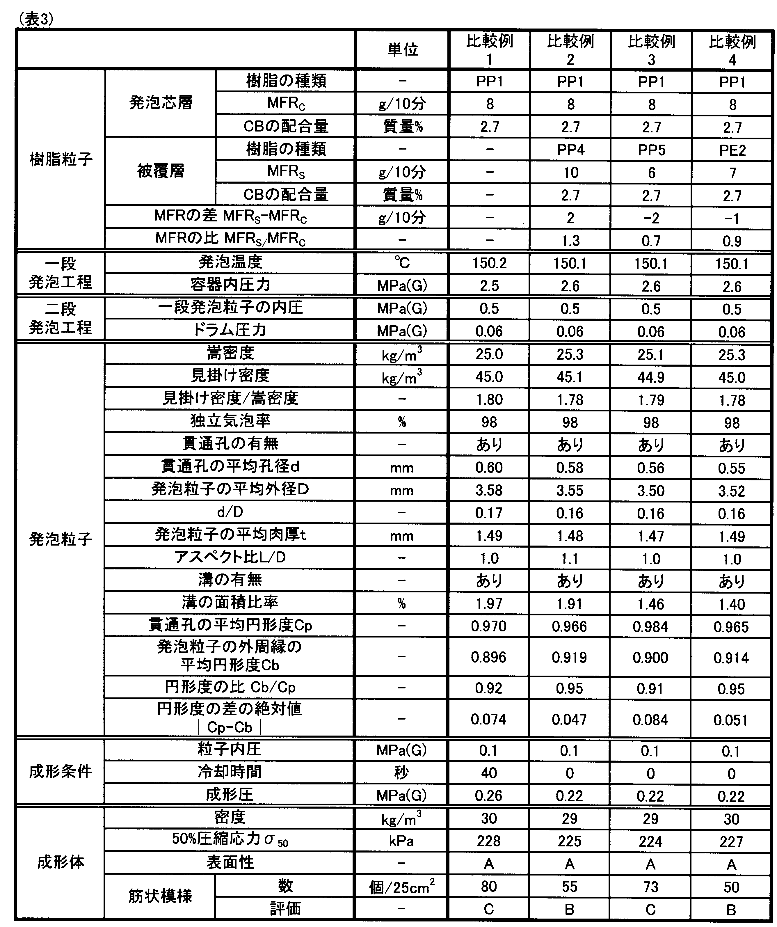

表2に示したように、実施例1~6の発泡粒子は、貫通孔を備えた筒状の形状を有しており、貫通孔の平均孔径d及び貫通孔の平均孔径dと発泡粒子の平均外径Dとの比d/Dがそれぞれ前記特定の範囲内である。また、これらの実施例の発泡粒子は、発泡芯層と、発泡芯層を被覆する被覆層とを有しており、被覆層を構成するポリオレフィン系樹脂のメルトマスフローレイトMFRSが前記特定の範囲内である。そのため、これらの実施例の発泡粒子を用いて型内成形を行うことにより、成形体の表面における筋状模様の形成を抑制し、良好な外観を有する成形体を得ることができた。また、これらの実施例の発泡粒子を用いることにより、水冷時間を短縮し、成形体の生産性を向上させることができた。 As shown in Table 2, the expanded beads of Examples 1 to 6 have a cylindrical shape with through holes, and the average hole diameter d of the through holes and the ratio d/D of the average hole diameter d of the through holes to the average outer diameter D of the expanded beads are each within the specific range. In addition, the expanded beads of these Examples have a foamed core layer and a coating layer that coats the foamed core layer, and the melt mass flow rate MFR S of the polyolefin resin that constitutes the coating layer is within the specific range. Therefore, by performing in-mold molding using the expanded beads of these Examples, it was possible to suppress the formation of streaky patterns on the surface of the molded body and obtain a molded body with a good appearance. In addition, by using the expanded beads of these Examples, it was possible to shorten the water cooling time and improve the productivity of the molded body.
一方、表3に示したように、比較例1の発泡粒子は被覆層を有しないため、成形体の表面に筋状模様が形成されやすかった。また、比較例1の発泡粒子を用いた場合、水冷時間が長かった。 On the other hand, as shown in Table 3, the expanded beads of Comparative Example 1 did not have a coating layer, so stripes were easily formed on the surface of the molded body. In addition, when the expanded beads of Comparative Example 1 were used, the water cooling time was long.
比較例2~4の発泡粒子における被覆層は、メルトマスフローレイトMFRSが前記特定の範囲よりも低いポリオレフィン系樹脂から構成されている。そのため、成形体の表面に筋状模様が形成されやすかった。 The coating layer in the expanded beads of Comparative Examples 2 to 4 was made of a polyolefin resin having a melt mass-flow rate MFR S lower than the above-mentioned specific range, and therefore streaky patterns were easily formed on the surface of the molded article.
表4に示すように、参考例1の発泡粒子における貫通孔の平均孔径dは前記特定の範囲よりも大きい。また、参考例2の発泡粒子は、貫通孔を有していない。表4に示すように、これらの参考例の発泡粒子は、被覆層を構成するポリオレフィン系樹脂のメルトフローレイトが前記特定の範囲よりも低いにもかかわらず、その発泡粒子からなる成形体の表面に筋状模様はほとんど形成されていない。従って、実施例1~6及び比較例1~4と参考例1~2との比較から、成形体の表面に筋状模様が形成される現象は、貫通孔を有するとともに、貫通孔の平均孔径dが前記特定の範囲内である発泡粒子の成形体に特有の現象であることが理解できる。なお、参考例1の発泡粒子は貫通孔の平均孔径が過度に大きく成形体の表面性が劣っていた。また、参考例2の発泡粒子は貫通孔を有しておらず、成形圧が高くなっていた。 As shown in Table 4, the average pore size d of the through holes in the expanded beads of Reference Example 1 is larger than the specific range. The expanded beads of Reference Example 2 do not have through holes. As shown in Table 4, the expanded beads of these Reference Examples have a polyolefin resin that constitutes the coating layer with a melt flow rate lower than the specific range, but the surface of the molded body made of the expanded beads is almost free of streaky patterns. Therefore, from a comparison of Examples 1 to 6 and Comparative Examples 1 to 4 with Reference Examples 1 and 2, it can be understood that the phenomenon of streaky patterns being formed on the surface of the molded body is a phenomenon specific to the molded body made of expanded beads that have through holes and have an average pore size d of the through holes within the specific range. The expanded beads of Reference Example 1 had an excessively large average pore size of the through holes, and the surface properties of the molded body were poor. The expanded beads of Reference Example 2 did not have through holes, and the molding pressure was high.
また、参考例3の発泡粒子は、着色顔料を含有していない。表4に示すように、これらの参考例の発泡粒子は、被覆層を構成するポリオレフィン系樹脂のメルトフローレイトが前記特定の範囲よりも低いにもかかわらず、その発泡粒子からなる成形体の表面に筋状模様は観察されなかった。これは、発泡粒子における溝の面積比率が比較的小さいことや、白色であるため筋状模様が観察されなかったこと等が理由であると考えられる。従って、実施例1~6及び比較例1~4と参考例3との比較から、成形体の表面に筋状模様が形成される現象は、着色剤としてのカーボンブラックが含有されている発泡粒子を成形した場合に、より発生しやすいことが理解できる。 Furthermore, the expanded beads of Reference Example 3 do not contain a coloring pigment. As shown in Table 4, in these expanded beads of Reference Examples, although the melt flow rate of the polyolefin resin constituting the coating layer is lower than the specific range, no streaky patterns were observed on the surface of the molded article made of the expanded beads. This is thought to be because the area ratio of the grooves in the expanded beads is relatively small and because the beads are white, no streaky patterns were observed. Therefore, from a comparison of Examples 1 to 6 and Comparative Examples 1 to 4 with Reference Example 3, it can be seen that the phenomenon of streaky patterns being formed on the surface of a molded article is more likely to occur when expanding beads containing carbon black as a coloring agent are molded.
以上、実施例に基づいて本発明に係るポリプロピレン系樹脂発泡粒子及びその製造方法の具体的な態様を説明したが、本発明に係るポリプロピレン系樹脂発泡粒子及びその製造方法の具体的な態様は実施例の態様に限定されるものではなく、本発明の趣旨を損なわない範囲で適宜構成を変更することができる。 Specific embodiments of the polypropylene-based resin expanded particles and the manufacturing method thereof according to the present invention have been described above based on the examples, but the specific embodiments of the polypropylene-based resin expanded particles and the manufacturing method thereof according to the present invention are not limited to those in the examples, and the configurations can be changed as appropriate within the scope of the spirit of the present invention.
Claims (11)
前記発泡粒子における前記貫通孔の平均孔径dが1mm未満であり、
前記発泡粒子の平均外径Dに対する前記貫通孔の平均孔径dの比d/Dが0.4以下であり、
前記発泡粒子は、ポリプロピレン系樹脂から構成される発泡芯層と、
ポリオレフィン系樹脂から構成され、前記発泡芯層の側周面を被覆する被覆層と、を有し、
前記発泡芯層及び前記被覆層が着色顔料を含み、
前記被覆層を構成する前記ポリオレフィン系樹脂の、JIS K7210-1:2014に基づき温度230℃、荷重2.16kgの条件で測定されるメルトマスフローレイトMFRSが15g/10分よりも高い、ポリプロピレン系樹脂発泡粒子。 A cylindrical expanded polypropylene resin bead having a through hole passing through the inside in the axial direction,
The average pore diameter d of the through holes in the expanded beads is less than 1 mm;
a ratio d/D of an average hole diameter d of the through holes to an average outer diameter D of the expanded beads is 0.4 or less;
The foamed beads include a foamed core layer made of a polypropylene-based resin,
A coating layer is made of a polyolefin resin and covers a side peripheral surface of the foamed core layer.
The foam core layer and the coating layer contain a color pigment,
The polyolefin resin constituting the coating layer has a melt mass-flow rate MFR S of more than 15 g/10 min, as measured according to JIS K7210-1:2014 under conditions of a temperature of 230° C. and a load of 2.16 kg.
ポリプロピレン系樹脂から構成されており、内部を軸方向に貫通する貫通孔を有する筒形状の芯層と、ポリオレフィン系樹脂から構成されており前記芯層の側周面を被覆する被覆層とを備えた多層樹脂粒子を作製する造粒工程と、
前記造粒工程の後、前記多層樹脂粒子を発泡させて前記発泡粒子を得る発泡工程と、を有し、
前記多層樹脂粒子における前記貫通孔の平均孔径drが0.25mm未満であり、
前記多層樹脂粒子の平均外径Drに対する前記貫通孔の平均孔径drの比dr/Drが0.4以下であり、
前記芯層及び前記被覆層が着色顔料を含み、
前記被覆層を構成する前記ポリオレフィン系樹脂の、JIS K7210-1:2014に基づき温度230℃、荷重2.16kgの条件で測定されるメルトマスフローレイトMFRSが15g/10分よりも高い、ポリプロピレン系樹脂発泡粒子の製造方法。 A method for producing expanded polypropylene resin beads, which is for producing cylindrical expanded polypropylene resin beads having through holes passing through the inside in an axial direction, comprising the steps of:
a granulation step for producing multilayer resin particles including a cylindrical core layer made of a polypropylene-based resin and having a through hole passing through the inside in the axial direction, and a coating layer made of a polyolefin-based resin and coating a lateral surface of the core layer;
and an expansion step of expanding the multilayer resin particles to obtain the expanded particles after the granulation step,
the through holes in the multilayered resin particles have an average pore diameter dr of less than 0.25 mm;
a ratio dr/Dr of an average pore diameter dr of the through holes to an average outer diameter Dr of the multilayer resin particles is 0.4 or less,
the core layer and the coating layer contain a color pigment;
The polyolefin resin constituting the coating layer has a melt mass-flow rate (MFR S ) of more than 15 g/10 min, as measured at a temperature of 230° C. and a load of 2.16 kg according to JIS K7210-1:2014.
Priority Applications (2)
| Application Number | Priority Date | Filing Date | Title |
|---|---|---|---|
| EP24823059.1A EP4711405A1 (en) | 2023-06-16 | 2024-03-28 | Polypropylene resin foamed particles and method for manufacturing same |
| CN202480032419.7A CN121241093A (en) | 2023-06-16 | 2024-03-28 | Polypropylene Resin Foamed Granules and Their Manufacturing Method |
Applications Claiming Priority (2)
| Application Number | Priority Date | Filing Date | Title |
|---|---|---|---|
| JP2023-099444 | 2023-06-16 | ||
| JP2023099444A JP2024180029A (en) | 2023-06-16 | 2023-06-16 | Polypropylene resin expanded particles and method for producing same |
Publications (1)
| Publication Number | Publication Date |
|---|---|
| WO2024257436A1 true WO2024257436A1 (en) | 2024-12-19 |
Family
ID=93851831
Family Applications (1)
| Application Number | Title | Priority Date | Filing Date |
|---|---|---|---|
| PCT/JP2024/012704 Ceased WO2024257436A1 (en) | 2023-06-16 | 2024-03-28 | Polypropylene resin foamed particles and method for manufacturing same |
Country Status (4)
| Country | Link |
|---|---|
| EP (1) | EP4711405A1 (en) |
| JP (1) | JP2024180029A (en) |
| CN (1) | CN121241093A (en) |
| WO (1) | WO2024257436A1 (en) |
Citations (3)
| Publication number | Priority date | Publication date | Assignee | Title |
|---|---|---|---|---|
| WO2021157369A1 (en) * | 2020-02-04 | 2021-08-12 | 株式会社ジェイエスピー | Polypropylene resin foam particles and polypropylene resin foam particle molded article |
| JP2022127578A (en) * | 2021-02-19 | 2022-08-31 | 株式会社ジェイエスピー | Foamed particle and method for producing the same |
| WO2023063081A1 (en) * | 2021-10-12 | 2023-04-20 | 株式会社ジェイエスピー | Expanded polypropylene-based-resin particles and method for producing molded expanded-particle object |
-
2023
- 2023-06-16 JP JP2023099444A patent/JP2024180029A/en active Pending
-
2024
- 2024-03-28 CN CN202480032419.7A patent/CN121241093A/en active Pending
- 2024-03-28 WO PCT/JP2024/012704 patent/WO2024257436A1/en not_active Ceased
- 2024-03-28 EP EP24823059.1A patent/EP4711405A1/en active Pending
Patent Citations (4)
| Publication number | Priority date | Publication date | Assignee | Title |
|---|---|---|---|---|
| WO2021157369A1 (en) * | 2020-02-04 | 2021-08-12 | 株式会社ジェイエスピー | Polypropylene resin foam particles and polypropylene resin foam particle molded article |
| JP2022127578A (en) * | 2021-02-19 | 2022-08-31 | 株式会社ジェイエスピー | Foamed particle and method for producing the same |
| WO2023063081A1 (en) * | 2021-10-12 | 2023-04-20 | 株式会社ジェイエスピー | Expanded polypropylene-based-resin particles and method for producing molded expanded-particle object |
| JP2023057790A (en) | 2021-10-12 | 2023-04-24 | 株式会社ジェイエスピー | Expanded polypropylene-based-resin particles and method for producing molded expanded-particle object |
Also Published As
| Publication number | Publication date |
|---|---|
| EP4711405A1 (en) | 2026-03-18 |
| JP2024180029A (en) | 2024-12-26 |
| CN121241093A (en) | 2025-12-30 |
Similar Documents
| Publication | Publication Date | Title |
|---|---|---|
| JP7805869B2 (en) | Polyolefin resin expanded particles and method for producing the same | |
| TWI400286B (en) | Expanded polypropylene resin beads, method of producing foam molding of expanded polypropylene resin beads and foam molding obtained by the method | |
| JP7735179B2 (en) | Expanded beads and their manufacturing method | |
| CN102471516B (en) | Polypropylene-based resin foamed particles and foamed particle molded products | |
| JP7664860B2 (en) | Polypropylene resin expanded beads and polypropylene resin expanded beads molded body | |
| EP2835243A2 (en) | Method for producing skin-covered polyolefin resin foamed molded article | |
| JP7735161B2 (en) | Method for producing expanded polypropylene resin beads | |
| US12589534B2 (en) | Polypropylene-based resin expanded beads and molded article thereof | |
| CN118660797B (en) | Method for producing thermoplastic resin foamed particle molded body | |
| JP7299555B2 (en) | POLYPROPYLENE RESIN EXPANDED BEET MOLDED PRODUCT AND METHOD FOR MANUFACTURING THE SAME | |
| JP7164660B2 (en) | Core material | |
| WO2024257436A1 (en) | Polypropylene resin foamed particles and method for manufacturing same | |
| US20250136777A1 (en) | Crystalline thermoplastic resin expanded bead, molded article of crystalline thermoplastic resin expanded beads, and method for producing same | |
| JP7787684B2 (en) | Polypropylene resin expanded beads and method for producing expanded bead molded articles | |
| CN118647497B (en) | Method for producing thermoplastic resin foamed particle molded body | |
| JP2023118117A (en) | CRYSTALLINE THERMOPLASTIC RESIN EXPANDED BEET MOLDED PRODUCT AND METHOD FOR MANUFACTURING THE SAME | |
| JP2023118116A (en) | CRYSTALLINE THERMOPLASTIC RESIN EXPANDED BEETLES, CRYSTALLINE THERMOPLASTIC RESIN EXPANDED BEET MOLDED PRODUCT AND METHOD FOR MANUFACTURING THE SAME | |
| EP4306583B1 (en) | Thermoplastic resin expanded bead and molded article of thermoplastic resin expanded beads | |
| EP4722280A1 (en) | Polypropylene-based resin expanded bead, molded article of polypropylene-based resin expanded beads, automotive bumper core, and automotive tool box | |
| WO2024135414A1 (en) | Polyethylene resin foam particle molded body and method for producing same | |
| WO2024247858A1 (en) | Polypropylene-based resin foam particle molded body and polypropylene-based resin foam particle |
Legal Events
| Date | Code | Title | Description |
|---|---|---|---|
| 121 | Ep: the epo has been informed by wipo that ep was designated in this application |
Ref document number: 24823059 Country of ref document: EP Kind code of ref document: A1 |
|
| WWE | Wipo information: entry into national phase |
Ref document number: CN2024800324197 Country of ref document: CN |
|
| WWE | Wipo information: entry into national phase |
Ref document number: 2024823059 Country of ref document: EP |
|
| ENP | Entry into the national phase |
Ref document number: 2024823059 Country of ref document: EP Effective date: 20251208 |
|
| ENP | Entry into the national phase |
Ref document number: 2024823059 Country of ref document: EP Effective date: 20251208 |
|
| ENP | Entry into the national phase |
Ref document number: 2024823059 Country of ref document: EP Effective date: 20251208 |
|
| ENP | Entry into the national phase |
Ref document number: 2024823059 Country of ref document: EP Effective date: 20251208 |
|
| NENP | Non-entry into the national phase |
Ref country code: DE |
|
| ENP | Entry into the national phase |
Ref document number: 2024823059 Country of ref document: EP Effective date: 20251208 |
|
| ENP | Entry into the national phase |
Ref document number: 2024823059 Country of ref document: EP Effective date: 20251208 |
|
| ENP | Entry into the national phase |
Ref document number: 2024823059 Country of ref document: EP Effective date: 20251208 |
|
| ENP | Entry into the national phase |
Ref document number: 2024823059 Country of ref document: EP Effective date: 20251208 |
|
| WWP | Wipo information: published in national office |
Ref document number: 2024823059 Country of ref document: EP |