WO2024257436A1 - Particules moussées de résine de polypropylène et procédé pour leur fabrication - Google Patents
Particules moussées de résine de polypropylène et procédé pour leur fabrication Download PDFInfo
- Publication number
- WO2024257436A1 WO2024257436A1 PCT/JP2024/012704 JP2024012704W WO2024257436A1 WO 2024257436 A1 WO2024257436 A1 WO 2024257436A1 JP 2024012704 W JP2024012704 W JP 2024012704W WO 2024257436 A1 WO2024257436 A1 WO 2024257436A1
- Authority
- WO
- WIPO (PCT)
- Prior art keywords
- expanded
- expanded beads
- beads
- less
- core layer
- Prior art date
- Legal status (The legal status is an assumption and is not a legal conclusion. Google has not performed a legal analysis and makes no representation as to the accuracy of the status listed.)
- Ceased
Links
Images




Classifications
-
- C—CHEMISTRY; METALLURGY
- C08—ORGANIC MACROMOLECULAR COMPOUNDS; THEIR PREPARATION OR CHEMICAL WORKING-UP; COMPOSITIONS BASED THEREON
- C08J—WORKING-UP; GENERAL PROCESSES OF COMPOUNDING; AFTER-TREATMENT NOT COVERED BY SUBCLASSES C08B, C08C, C08F, C08G or C08H
- C08J9/00—Working-up of macromolecular substances to porous or cellular articles or materials; After-treatment thereof
- C08J9/16—Making expandable particles
Definitions
- the present invention relates to polypropylene resin foam particles and a method for producing the same.
- Polypropylene resin foamed bead molded bodies are used in a variety of applications because they are lightweight and have excellent shock-absorbing properties and rigidity.
- Polypropylene resin foamed bead molded bodies are manufactured, for example, by a method called in-mold molding, in which polypropylene resin foamed beads are filled into a mold, and then steam is supplied into the mold to heat it.
- in-mold molding when steam is supplied into the mold, the foamed beads undergo secondary expansion and their surfaces melt. This causes the foamed beads in the mold to fuse together, resulting in a molded body with a shape that corresponds to the shape of the mold cavity.
- the molded body immediately after molding is prone to expanding due to secondary expansion, so it is cooled in the mold with water or air and then released from the mold.
- Patent Document 1 describes expanded polypropylene resin beads that can be used to form such expanded bead moldings, which contain carbon black as a colorant and are obtained by expanding cylindrical polypropylene resin beads having through holes in two stages. Expanded bead moldings molded using expanded polypropylene resin beads obtained by the method of Patent Document 1 have a high degree of blackness and suppressed color unevenness.
- the present invention was made in consideration of this background, and aims to provide polypropylene resin foam particles that can be used to form foamed bead moldings with few streaks and good appearance, and a method for producing the same.
- One aspect of the present invention is the polypropylene resin foam particles according to the following [1] to [10].
- the average pore diameter d of the through holes in the expanded beads is less than 1 mm;
- a ratio d/D of an average hole diameter d of the through holes to an average outer diameter D of the expanded beads is 0.4 or less;
- the foamed beads include a foamed core layer made of a polypropylene-based resin,
- a coating layer is made of a polyolefin resin and covers a side peripheral surface of the foamed core layer.
- the foam core layer and the coating layer contain a color pigment
- the polyolefin resin constituting the coating layer has a melt mass-flow rate MFR S of more than 15 g/10 min, as measured according to JIS K7210-1:2014 under conditions of a temperature of 230° C. and a load of 2.16 kg.
- Another aspect of the present invention is the method for producing expanded polypropylene resin particles according to [11] below.
- a method for producing expanded polypropylene-based resin beads which is a cylindrical expanded polypropylene-based resin bead having a through hole passing through the inside in an axial direction, comprising the steps of: a granulation step for producing multilayer resin particles including a cylindrical core layer made of a polypropylene-based resin and having a through hole passing through the inside in the axial direction, and a coating layer made of a polyolefin-based resin and coating a lateral surface of the core layer; and an expansion step of expanding the multilayer resin particles to obtain the expanded particles after the granulation step, the through holes in the multilayered resin particles have an average pore diameter dr of less than 0.25 mm; a ratio dr/Dr of an average pore diameter dr of the through holes to an average outer diameter Dr of the multilayer resin particles is 0.4 or less, the core layer and the coating layer contain a color pigment;
- the polyolefin resin constituting the coating layer has a melt mass-flow rate (MFR S )
- the above aspect provides polypropylene resin foam particles capable of forming foamed bead moldings with few streaks and good appearance, and a method for producing the same.
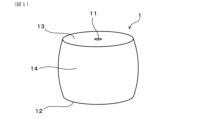
- FIG. 1 is a perspective view of an expanded bead.
- FIG. 2 is a cross-sectional view of the expanded bead of FIG. 1 taken along a cross section passing through the central axis of the expanded bead.
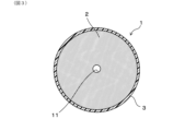
- FIG. 3 is a cross-sectional view taken along line III-III in FIG.
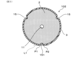
- FIG. 4 is a perspective view showing an example of an expanded bead having a groove on its side peripheral surface.
- FIG. 5 is a cross-sectional view taken along line VV in FIG.
- FIG. 6 is an explanatory diagram showing a method for calculating the area of the high-temperature peak.
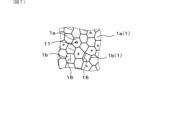
- FIG. 7 is a plan view showing a schematic view of the surface of the molded body.
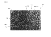
- FIG. 8 is a photograph showing the appearance of the expanded bead molding of Example 1.
- FIG. 9 is a photograph showing the appearance of the expanded bead molding of Comparative Example 3.
- the expanded polypropylene resin bead 1 (hereinafter, also referred to as “expanded bead 1" or simply “expanded bead”) has a cylindrical shape with a through hole 11 penetrating the inside in the axial direction. More specifically, the expanded bead 1 has a bottom surface 12, a top surface 13 disposed above the bottom surface 12 and having a shape generally identical to that of the bottom surface 12, and a side peripheral surface 14 connecting the edge of the bottom surface 12 and the edge of the top surface 13. As shown in FIG. 2, the through hole 11 penetrates the inside of the expanded bead 1 in the axial direction and opens to the bottom surface 12 and the top surface 13.
- the aforementioned cylindrical shape includes, for example, a cylinder or a square tube as shown in FIG. 1.
- the number of through holes 11 provided in the expanded bead 1 may be one or more.
- the expanded beads 1 have an expanded core layer 2 made of a polypropylene resin and a coating layer 3 made of a polyolefin resin and coating the side surface of the expanded core layer 2.
- the coating layer 3 is provided on the outer surface of the expanded beads.
- the expanded core layer 2 and the coating layer 3 contain a coloring pigment.
- the melt mass-flow rate MFR S of the polyolefin resin constituting the coating layer is higher than 15 g/10 min.
- the formation of a streaky pattern on the surface of a polypropylene resin expanded bead molding (hereinafter also referred to as a "molded body").
- a polyolefin resin having a high melt mass-flow rate MFR S for the coating layer, the formation of a streaky pattern on the surface of the molded body can be suppressed without impairing the rigidity of the expanded core layer. Therefore, by using the expanded beads, the formation of a streaky pattern can be suppressed while maintaining the rigidity of the molded body.
- the average pore diameter d of the through holes in the expanded beads is less than 1 mm.
- the average pore diameter d of the through holes is more preferably 0.95 mm or less, further preferably 0.92 mm or less, and more preferably 0.
- the thickness is 0.90 mm or less, and most preferably 0.85 mm or less.
- curing step refers to a step of curing a molded product released from a mold during the manufacturing process of the molded product at 60°C. This refers to a process in which the mixture is left to stand for a predetermined period of time in a high-temperature atmosphere adjusted to a temperature of about 100 to 80°C.
- the average pore diameter d of the through holes is too large, it may take an excessively long time to dry the molded body. In addition, there is a risk that gaps between the foamed particles and irregularities caused by the through holes may easily form on the surface of the molded body, and the rigidity of the molded body may decrease.
- the average diameter d of the through holes is preferably 0.1 mm or more.
- the through holes of the foamed beads are prevented from being crushed and blocked during molding in the mold, and the effect of the through holes can be more reliably exerted.
- the average diameter d of the through holes is more preferably 0.2 mm or more, even more preferably 0.3 mm or more, particularly preferably 0.4 mm or more, and most preferably 0.5 mm or more.
- the upper and lower limits of the average pore diameter d of the through holes described above can be combined in any way.
- the preferred range of the average pore diameter d of the through holes may be, for example, 0.1 mm or more and less than 1 mm, 0.2 mm or more and 0.95 mm or less, 0.3 mm or more and 0.92 mm or less, 0.4 mm or more and 0.90 mm or less, or 0.5 mm or more and 0.85 mm or less.
- the open-cell structure is formed by a complex connection of voids formed when the through holes of multiple foamed beads are connected to each other, voids formed when the through holes of the foamed beads are connected to the gaps between the foamed beads, voids formed when the gaps between the foamed beads are connected, and open-cell parts of the foamed beads that make up the molded body.
- the open cell structure is connected to the outside of the molded body, it is believed that when a molded body with an appropriate open cell ratio is released from the mold, outside air will quickly flow through the open cell structure to the bubbles inside the molded body. And as outside air flows into the bubbles inside the molded body, the internal pressure of the entire molded body tends to quickly balance with the atmospheric pressure outside the molded body. As a result of the above, it is believed that the dimensions of the molded body tend to stabilize early, and significant shrinkage and deformation of the molded body can be suppressed even if a curing process is not performed.
- the expanded beads have through holes, it is believed that when steam is supplied into the mold, the steam can pass through the through holes. This makes it easier for the steam to reach the inside of the mold, and it is believed that the entire expanded beads in the mold can be easily heated. Therefore, even under low molding temperatures during in-mold molding, a molded body with excellent fusion properties and a good appearance can be obtained. As a result, the amount of heat that the expanded beads receive from the steam during in-mold molding can be kept low. In addition, the internal temperature of the molded body after release from the mold is prevented from becoming excessively high. As a result of these, it is believed that the dimensions of the molded body after in-mold molding can be stabilized more easily early.
- the molding temperature is likely to be high and it may be difficult to form a sufficient open cell structure in the resulting molded body. Therefore, in this case, it is difficult to prevent significant shrinkage, deformation, etc. of the molded body when the curing process is omitted. Also, in this case, the secondary foaming property of the expanded beads may become excessively high, and the cooling time in the mold may become long.
- the average pore diameter d of the through holes of the expanded beads is determined as follows. First, the expanded bead is cut in a plane perpendicular to the axial direction at the position where its cross-sectional area is maximum, exposing the cut surface as shown in Figure 3. Next, a photograph of the cut surface is taken, and the cross-sectional area (specifically, the opening area) of the through holes 11 in the cut surface is calculated. Then, the diameter of an imaginary perfect circle having the same area as the cross-sectional area of the through holes 11 is calculated, and this value is taken as the pore diameter of the through holes of each expanded bead. Note that in this specification, the position where the cross-sectional area of the expanded bead is maximum can be identified, for example, by 3D scanning the external shape of the expanded bead.
- the above operation is performed for 50 or more expanded beads 1, and the arithmetic mean value of the diameters of the through holes 11 in these expanded beads 1 is defined as the average diameter d of the through holes. Even if the cross-sectional area of the through holes 11 of each expanded bead 1 is not uniform in the axial direction, the average diameter d of the through holes of the expanded beads is determined using the diameter of the through holes 11 in the cut surface where the cross-sectional area of the expanded beads 1 is maximum, as described above.
- the average pore diameter d of the through holes can be adjusted to the above-mentioned specific range by adjusting the average pore diameter dr of the through holes in the multilayer resin particles described below and the bulk density of the expanded beads.
- the average pore diameter d can be more easily adjusted to a smaller value.
- the average circularity Cp of the through holes in a cross section obtained by cutting the expanded beads at a position where the cross-sectional area is maximum along a plane perpendicular to the axial direction is preferably 0.90 or more, more preferably 0.92 or more, and even more preferably 0.95 or more.
- the effect of improving the moldability of the expanded beads and the effect of shortening the cooling time during molding can be more easily obtained.
- the through holes are less likely to be crushed by external forces.
- the through holes are less likely to be blocked, and the moldability during in-mold molding can be further improved. Furthermore, by performing in-mold molding using the expanded beads, a molded body having excellent rigidity can be more easily obtained.
- the above operation is carried out for 50 or more randomly selected expanded beads 1, and the arithmetic mean value of the circularity of the through holes 11 in these expanded beads 1 is taken as the average circularity Cp of the through holes. Note that even if the cross-sectional shape of the through holes 11 of each expanded bead 1 is not uniform in the axial direction, the average circularity Cp of the through holes is determined based on the cross-sectional shape of the through holes at the position where the area of the cut surface of the expanded bead 1 is maximum, as described above.
- the average circularity Cp of the through holes can be adjusted to the above range, for example, by changing the shape of the die for forming the through holes in the granulation process of the multilayer resin particles described below, or by adjusting the water temperature when cooling the strands, which is usually about 25°C, to a lower water temperature (for example, 15°C or lower).
- the upper limit of the average circularity Cp of the through holes is 1.
- the preferred range of the average circularity Cp of the through holes may be, for example, 0.90 or more and 1 or less, 0.92 or more and 1 or less, or 0.95 or more and 1 or less.
- the ratio d/D of the average hole diameter d of the through holes to the average outer diameter D of the expanded beads is 0.4 or less.
- the ratio d/D of the average hole diameter d of the through holes to the average outer diameter D of the expanded beads is preferably 0.35 or less, more preferably 0.3 or less, and even more preferably 0.25 or less. If the ratio d/D is too high, the secondary expandability of the expanded beads during in-mold molding may decrease, leading to a decrease in the surface properties and rigidity of the molded body.
- the ratio d/D of the average pore size d of the through holes to the average outer diameter D of the expanded beads is 0.1 or more.
- the through holes of the expanded beads are less likely to be crushed even when an external force is applied, so that the effect of the through holes can be more reliably exerted.
- the preferable range of the ratio d/D of the average pore size d of the through holes to the average outer diameter D of the expanded beads may be, for example, 0.1 or more and 0.4 or less, 0.1 or more and 0.35 or less, 0.1 or more and 0.3 or less, or 0.1 or more and 0.25 or less.
- the average outer diameter D of the foamed beads is preferably 2 mm or more, more preferably 2.5 mm or more, and even more preferably 3 mm or more.
- the average outer diameter D of the foamed beads is preferably 8 mm or less, more preferably 5 mm or less, and even more preferably 4.5 mm or less.
- the upper and lower limits of the average outer diameter D of the expanded beads described above can be combined in any way.
- the preferred range of the average outer diameter D of the expanded beads may be, for example, 2 mm or more and 8 mm or less, 2.5 mm or more and 5 mm or less, or 3 mm or more and 4.5 mm or less.
- the method for calculating the average outer diameter D of the expanded beads described above is as follows. First, the expanded bead 1 is cut in a plane perpendicular to the axial direction at the position where its cross-sectional area is maximum, exposing the cut surface of the expanded bead 1 as shown in Figure 3. The cross-sectional area of the expanded bead 1, including the through holes 11, in this cut surface (i.e., the area of the region surrounded by the outer edge of the expanded bead 1 in the cut surface) is calculated. Then, the diameter of an imaginary perfect circle whose area is equal to the cross-sectional area of the expanded bead 1 is determined as the outer diameter of each expanded bead 1.
- the outer diameters of 50 or more expanded beads 1 are calculated, and the arithmetic mean value of the outer diameters of these expanded beads 1 is taken as the average outer diameter D of the expanded beads. Even if the cross-sectional area of each expanded bead 1 is not uniform in the axial direction, the average outer diameter D of the expanded beads is determined based on the cross-sectional area of the expanded beads 1 at the cut surface where the cross-sectional area of the expanded beads 1 is maximum, as described above.
- the average circularity Cb of the outer peripheral edge of the expanded beads in a cross section obtained by cutting the expanded beads at a position where the cross-sectional area is maximum along a plane perpendicular to the axial direction is preferably 0.95 or more, more preferably 0.96 or more.
- the average circularity Cb of the outer peripheral edge of the expanded beads is obtained as follows. First, the expanded beads are cut at the position where the cross-sectional area is maximum along a plane perpendicular to the axial direction to expose the cut surface as shown in FIG. 3. Next, a photograph of the cut surface of the expanded beads 1 is taken, and the cross-sectional area Sb of the expanded beads 1 including the through holes 11 (i.e., the area of the region surrounded by the outer peripheral edge of the expanded beads 1 on the cut surface) and the circumferential length Lb of the outer peripheral edge of the expanded beads 1 (i.e., the length of the outer peripheral edge of the expanded beads 1 on the cut surface) are measured.
- the cross-sectional area Sb of the expanded beads 1 including the through holes 11 i.e., the area of the region surrounded by the outer peripheral edge of the expanded beads 1 on the cut surface
- the circumferential length Lb of the outer peripheral edge of the expanded beads 1 i.e., the length of the outer peripheral edge of the expanded beads
- the above operation is carried out for 50 or more randomly selected expanded beads 1, and the arithmetic mean value of the circularity of these expanded beads 1 is taken as the average circularity Cb of the outer peripheral edge of the expanded beads.
- the average circularity Cb of the outer peripheral edge of the expanded beads is determined based on the cross-sectional shape of the expanded beads 1 at the cut surface where the cross-sectional area of the expanded beads 1 is maximum, as described above.
- the upper limit of the average circularity Cb of the outer peripheral edge is 1.
- the preferred range of the average circularity Cb of the outer peripheral edge of the expanded beads may be 0.95 or more and 1 or less, or 0.96 or more and 1 or less.
- the ratio Cb/Cp of the average circularity Cb of the outer periphery of the expanded beads to the average circularity Cp of the through holes of the expanded beads is preferably 0.96 or more and 1.05 or less, and more preferably 0.98 or more and 1.02 or less. In this case, it is possible to obtain a molded body with excellent rigidity while more reliably exerting the moldability improvement effect of the through holes, and it is possible to more effectively suppress the formation of streaky patterns on the surface of the molded body.
- of the difference between the average circularity Cb of the outer periphery of the expanded beads and the average circularity Cp of the through holes is preferably 0.03 or less, more preferably 0.01 or less, and even more preferably 0.008 or less.
- the average circularity Cb of the outer periphery of the expanded beads can be adjusted to fall within the above-mentioned specific range, for example, by forming the coating layer from a polyolefin resin having a melt mass-flow rate MFR S within the above-mentioned specific range.
- the ratio of the total cross-sectional area of the grooves to the cross-sectional area of the expanded beads excluding the through holes in a cross section obtained by cutting the expanded beads along a plane perpendicular to the axial direction at the position where the cross-sectional area is maximum is preferably 3% or less, more preferably 1.5% or less, even more preferably 1.2% or less, even more preferably 1% or less, particularly preferably 0.5% or less, and most preferably 0%, i.e., the expanded beads have no grooves on their side peripheral surfaces.
- the expanded bead 102 shown in FIG. 4 has a cylindrical shape surrounded by a bottom surface 12, a top surface 13, and a side surface 14, and has a through hole 11 passing through its interior in the axial direction.
- Three grooves 15 are formed on the side surface 14 of the expanded bead 102, positioned at approximately equal intervals in the circumferential direction of the expanded bead 102.
- the method for calculating the area ratio of the total cross-sectional area of the grooves in the expanded beads is as follows. First, the expanded beads 102 are cut in a plane perpendicular to the axial direction at the position where the cross-sectional area is maximum, exposing the cut surface as shown in Figure 5. Next, a photograph of the cut surface of the expanded beads 102 is taken, and the cross-sectional area of the expanded beads 102 excluding the through holes 11 (i.e., the area of the region enclosed by the outer peripheral edge and the inner peripheral edge of the expanded beads 102 on the cut surface) is measured.
- the through holes 11 i.e., the area of the region enclosed by the outer peripheral edge and the inner peripheral edge of the expanded beads 102 on the cut surface
- a tangent line L1 is drawn around each groove 15 in the photograph of the cut surface of the expanded bead 102, tangent to the contour of the expanded bead 102 at two points P1 and P2, and does not pass through the interior of the expanded bead 102.
- the area of the region enclosed by the contour of the expanded bead 102 and the tangent line L1 is then calculated, and this area is taken as the cross-sectional area of each groove 15.
- the cross-sectional area of each groove 15 is the area of the region 151 shown by the diagonal lines in Figure 5.
- the above operation is carried out for all grooves 15, and these are summed up to calculate the total cross-sectional area of the grooves 15 in each expanded bead 102.
- the total cross-sectional area of the grooves 15 thus obtained is divided by the cross-sectional area of the expanded beads 102 excluding the aforementioned through holes 11 to calculate the ratio of the total cross-sectional area of the grooves 15 to the cross-sectional area of the expanded beads 102 for each expanded bead 102.
- the above operation is carried out for 100 or more expanded beads 102, and the arithmetic mean value of the ratios for these expanded beads 102 is taken as the area ratio of the total cross-sectional area of the grooves in the expanded beads.
- the coating layer By forming the coating layer from a polyolefin resin having a melt mass-flow rate MFR S within the above-mentioned specific range, the formation of grooves on the circumferential side surface of the expanded beads can be suppressed, and the area ratio of the total cross-sectional area of the grooves in the expanded beads can be easily adjusted to within the above-mentioned range.
- the reason for this is not necessarily clear, but it is thought that the residual stress remaining in the resin particles obtained in the granulation step described below is alleviated, making it difficult for wrinkles to form in the expanded beads, and that the coating layer is more easily formed uniformly on the circumferential side surface of the obtained expanded beads.
- the average wall thickness t of the expanded beads is preferably 1.2 mm or more and 2 mm or less.
- the secondary expandability of the expanded beads during in-mold molding can be further improved.
- the expanded beads having an average wall thickness t within the specific range are less likely to be crushed by external forces, so that the rigidity of the molded body obtained by in-mold molding of the expanded beads can be further improved.
- the average wall thickness t of the expanded beads is more preferably 1.3 mm or more and 2 mm or less, and even more preferably 1.5 mm or more and 2 mm or less.
- the apparent density of the expanded beads is preferably 10 kg/m 3 or more and 100 kg/m 3 or less, more preferably 20 kg/m 3 or more and 80 kg/m 3 or less, even more preferably 25 kg/m 3 or more and 60 kg/m 3 or less, and particularly preferably 30 kg/m 3 or more and 50 kg/m 3 or less.
- a lightweight molded body having excellent rigidity can be easily obtained.
- the expanded beads can omit the curing step even when the apparent density is low, so that a lightweight molded body having a desired shape can be produced without curing.
- the method for calculating the apparent density of expanded beads is as follows. First, the expanded beads are left to stand for one day in an environment of 50% relative humidity, 23°C temperature, and 1 atm pressure to adjust the state of the expanded beads. After measuring the mass (unit: g) of the expanded beads, the expanded beads are submerged in a measuring cylinder containing alcohol (e.g., ethanol) at 23°C using a wire net or the like, and the volume (unit: L) of the expanded beads is calculated from the rise in the liquid level. The mass of the expanded beads is then divided by the volume of the expanded beads to convert the value into units, thereby calculating the apparent density (unit: kg/ m3 ) of the expanded beads.
- alcohol e.g., ethanol
- the foamed core layer of the foamed beads is composed of a polypropylene-based resin.
- the polypropylene-based resin refers to a homopolymer of a propylene monomer and a propylene-based copolymer containing 50% by mass or more of a structural unit derived from propylene.
- the foamed core layer may contain one type of polypropylene-based resin or two or more types of polypropylene-based resins.
- the foamed core layer is more preferably composed of a propylene-based copolymer in which propylene is copolymerized with another monomer.
- propylene-based copolymers include copolymers of propylene and an ⁇ -olefin having 4 to 10 carbon atoms, such as ethylene-propylene copolymer, butene-propylene copolymer, hexene-propylene copolymer, and ethylene-propylene-butene copolymer. These copolymers may be, for example, random copolymers or block copolymers, but are preferably random copolymers.
- the melting point Tmc of the polypropylene resin constituting the foamed core layer is preferably 155°C or less.
- a molded body having excellent appearance and rigidity can be molded at a lower molding temperature (i.e., low molding pressure).
- the melting point Tmc of the polypropylene resin constituting the foamed core layer is preferably 152°C or less, and more preferably 148°C or less.
- the melting point Tmc of the polypropylene resin constituting the foamed core layer is preferably 135°C or more, more preferably 138°C or more, and even more preferably 140°C or more.
- the preferred range of the melting point Tmc of the polypropylene resin constituting the foamed core layer may be, for example, 135°C or more and 155°C or less, 138°C or more and 152°C or less, or 140°C or more and 148°C or less.
- the melting point Tmc of the polypropylene resin constituting the foamed core layer can be determined based on the DSC curve obtained by performing differential scanning calorimetry (DSC) based on JIS K7121-1987. Specifically, a test piece made of polypropylene resin is prepared, and the condition of the test piece is adjusted according to "(2) Measurement of melting temperature after a certain heat treatment". The heating and cooling rates in the condition adjustment are 10°C/min, and the temperature range is from 30°C to 200°C. The test piece thus adjusted is heated from 30°C to 200°C at a heating rate of 10°C/min to obtain a DSC curve.
- the apex temperature of the melting peak that appears on the DSC curve is the melting point Tmc of the polypropylene resin. Note that if multiple melting peaks appear on the DSC curve, the apex temperature of the melting peak with the largest area is the melting point Tmc.
- the melt mass-flow rate MFR C of the polypropylene-based resin constituting the foamed core layer is preferably 5 g/10 min or more, more preferably 6 g/10 min or more, and even more preferably 7 g/10 min or more. In this case, the foamability and moldability can be further improved.
- the melt mass-flow rate MFR C of the polypropylene-based resin constituting the foamed core layer is preferably 12 g/10 min or less, and more preferably 10 g/10 min or less.
- the upper and lower limits of the melt mass flow rate MFR C described above can be combined arbitrarily.
- the preferred range of the melt mass flow rate MFR C of the polypropylene resin constituting the foamed core layer may be 5 g/10 min or more and 12 g/10 min or less, 6 g/10 min or more and 12 g/10 min or less, or 7 g/10 min or more and 10 g/10 min or less.
- the MFR C of the polypropylene resin constituting the foamed core layer is a value measured based on JIS K7210-1:2014 under the conditions of a test temperature of 230° C. and a load of 2.16 kg.
- the foamed beads can suppress the formation of streaky patterns on the surface of the molded article by covering the side peripheral surface of the foamed core layer with a covering layer made of a polyolefin resin having a high melt mass-flow rate MFR S.
- a polyolefin resin having a high melt mass-flow rate MFR S can be used as the resin constituting the covering layer
- a polypropylene resin having a relatively low melt mass-flow rate MFR C for example, within the above range, can be used as the resin constituting the foamed core layer.
- the foamed core layer may contain polymers other than polypropylene-based resins, provided that the above-mentioned effects are not impaired.
- polymers include thermoplastic resins other than polypropylene-based resins, such as polyethylene-based resins and polystyrene-based resins, and thermoplastic elastomers.
- the content of polymers other than polypropylene-based resins in the foamed core layer is preferably 20% by mass or less, more preferably 10% by mass or less, even more preferably 5% by mass or less, and particularly preferably 0, i.e., the foamed core layer contains substantially only polypropylene-based resins as polymers.
- the foamed core layer may also contain additives such as bubble regulators, crystal nucleating agents, flame retardants, flame retardant assistants, plasticizers, antistatic agents, antioxidants, UV inhibitors, light stabilizers, conductive fillers, and antibacterial agents, so long as the additives do not impair the aforementioned effects.
- additives such as bubble regulators, crystal nucleating agents, flame retardants, flame retardant assistants, plasticizers, antistatic agents, antioxidants, UV inhibitors, light stabilizers, conductive fillers, and antibacterial agents, so long as the additives do not impair the aforementioned effects.
- the content of the additives in the foamed core layer is preferably, for example, 0.01 parts by mass or more and 10 parts by mass or less per 100 parts by mass of the polypropylene resin.
- the side surface of the foamed core layer in the expanded beads is covered with a coating layer made of a polyolefin resin.
- the coating layer of the expanded beads may be in a foamed state or a non-foamed state, but is preferably in a substantially non-foamed state.
- non-foamed state includes a state in which the coating layer is not foamed and does not contain bubbles, and a state in which bubbles have disappeared after foaming, and means that there is almost no bubble structure in the coating layer.
- "A to B" representing a numerical range is synonymous with "A or more and B or less” and represents a numerical range including the endpoints A and B of the numerical range.
- the polyolefin resin constituting the coating layer may be, for example, a polyethylene resin, a polypropylene resin, or a polybutene resin. From the viewpoint of adhesion to the foamed core layer, the polyolefin resin constituting the coating layer is preferably a polyethylene resin or a polypropylene resin, and more preferably a polypropylene resin.
- the polypropylene resin constituting the coating layer may be, for example, an ethylene-propylene copolymer, a butene-propylene copolymer, an ethylene-propylene-butene copolymer, or a propylene homopolymer.
- the polypropylene resin constituting the coating layer is preferably an ethylene-propylene copolymer or an ethylene-propylene-butene copolymer.
- the polyethylene resin constituting the coating layer may be, for example, a linear low-density polyethylene (PE-LLD), a low-density polyethylene (PE-LD), a medium-density polyethylene (PE-MD), or a high-density polyethylene (PE-HD).
- the polyolefin resin constituting the coating layer has a melt mass-flow rate MFR S higher than 15 g/10 min.
- MFR S melt mass-flow rate of the polyolefin resin constituting the coating layer
- MFR C melt mass-flow rate of the polypropylene resin constituting the foamed core layer
- the difference MFR -MFR between the melt mass-flow rate MFR of the polyolefin resin constituting the coating layer and the melt mass-flow rate MFR of the polypropylene resin constituting the foamed core layer is preferably 10 g/10 min or more, and more preferably 12 g/10 min or more.
- the ratio MFR / MFR of the melt mass-flow rate MFR of the polyolefin resin constituting the coating layer to the melt mass-flow rate MFR of the polypropylene resin constituting the foamed core layer is preferably 2 or more, and more preferably 2.5 or more.
- the difference MFR -MFR between the melt mass-flow rate MFR of the polyolefin resin constituting the coating layer and the melt mass-flow rate MFR of the polypropylene resin constituting the foamed core layer is preferably 30 g/10 min or less.
- the ratio MFR / MFR of the melt mass-flow rate MFR of the polyolefin resin constituting the coating layer to the melt mass-flow rate MFR of the polypropylene resin constituting the foamed core layer is preferably 5 or less, and more preferably 4 or less.
- the upper and lower limits of the difference MFR S -MFR C described above can be combined arbitrarily.
- the preferred range of the difference MFR S -MFR C may be 10 g/10 min or more and 30 g/10 min or less, or 12 g/10 min or more and 30 g/10 min or less.
- the upper and lower limits of the ratio MFR S /MFR C described above can be combined arbitrarily.
- the ratio MFR S /MFR C may be preferably in the range of 2 or more and 5 or less, or 2.5 or more and 4 or less.
- the MFR of the polyolefin resin constituting the coating layer is a value measured under conditions of a test temperature of 230° C. and a load of 2.16 kg based on JIS K7210-1: 2014. Even when the coating layer is made of a polyethylene resin, the MFR is measured under conditions of a test temperature of 230° C. and a load of 2.16 kg.
- the melting point Tms of the polyolefin resin constituting the coating layer is preferably lower than the melting point Tmc of the polypropylene resin constituting the foamed core layer.
- the difference Tmc-Tms between the melting point Tmc of the polypropylene resin constituting the foamed core layer and the melting point Tms of the polyolefin resin constituting the coating layer is preferably more than 0°C and less than 40°C, more preferably 3°C to 35°C, and even more preferably 5°C to 30°C.
- the method for measuring the melting point Tms of the polyolefin resin that constitutes the coating layer is the same as the method for measuring the melting point Tmc of the polypropylene resin that constitutes the foamed core layer described above, except that a polyolefin resin is used instead of a polypropylene resin.
- the coating layer may contain additives such as crystal nucleating agents, flame retardants, flame retardant assistants, plasticizers, antistatic agents, antioxidants, UV inhibitors, light stabilizers, conductive fillers, and antibacterial agents, so long as they do not impair the aforementioned effects.
- the content of the additives in the coating layer is preferably, for example, 0.01 parts by mass or more and 10 parts by mass or less per 100 parts by mass of the polyolefin resin.
- the foam core layer and the coating layer contain a coloring pigment.
- the coloring pigment may be any color other than white, and may be any color having various tones, such as black, red, blue, yellow, and green pigments.
- the coloring pigment may be an inorganic pigment or an organic pigment.
- Inorganic pigments include, for example, carbon particles such as carbon black; chromates such as yellow lead, zinc yellow, and barium yellow; ferrocyanides such as Prussian blue; sulfides such as cadmium yellow and cadmium red; oxides such as red iron oxide; and silicates such as ultramarine.
- Organic pigments include, for example, azo pigments such as monoazo pigments, disazo pigments, azo lakes, condensed azo pigments, and chelate azo pigments; and polycyclic pigments such as phthalocyanines, anthraquinones, perylenes, perinones, thioindigo, quinacridones, dioxazines, isoindolinones, and quinophthalones.
- the foam core layer may contain one type of color pigment or may contain two or more types of color pigments.
- the coating layer may contain one type of color pigment or may contain two or more types of color pigments.
- the color tone of the color pigment in the foam core layer and the color pigment in the coating layer may be the same or different. From the viewpoint of imparting a luxurious feel to the molded article, it is preferable that the color pigment in the foam core layer and the coating layer is a black pigment. It is preferable to use carbon particles as the black pigment, and more specifically, it is preferable to use carbon black.
- the content of the color pigment in the foamed core layer is 0.1% by mass or more and 5% by mass or less, and the content of the color pigment in the coating layer is 0.1% by mass or more and 5% by mass or less.
- the desired color tone can be imparted to the foamed particles while sufficiently ensuring the secondary foaming and fusion properties of the foamed particles during molding in the mold. This makes it easier to obtain a molded body having a desired color tone and good appearance.
- the content of the color pigment in the foamed core layer is 0.3% by mass or more and 4.5% by mass or less
- the content of the color pigment in the coating layer is 0.3% by mass or more and 4.5% by mass or less
- the content of the color pigment in the foamed core layer is 0.5% by mass or more and 4% by mass or less
- the content of the color pigment in the coating layer is 0.5% by mass or more and 4% by mass or less.
- the reason why the streaky pattern is formed on the surface of the molded body is thought to be, for example, that the grooves formed on the side peripheral surface of the expanded beads described above are exposed on the surface of the molded body.
- Such streaky patterns on the surface of the molded body are particularly noticeable in molded bodies made by molding expanded beads containing color pigments. This is thought to be because the streaky pattern often appears lighter in color than the surrounding area and is less noticeable in white molded bodies that do not contain color pigments, and because, in the past, the average circularity of the outer peripheral edge of expanded beads containing color pigments was particularly likely to be low.
- the expanded beads prevent the deterioration of the appearance caused by the streaky pattern even in colored molded bodies obtained from expanded beads containing color pigments.
- the closed cell ratio of the expanded beads is preferably 90% or more, more preferably 92% or more, and even more preferably 95% or more.
- the closed cell ratio of the expanded beads can be measured using an air comparison type specific gravity meter based on ASTM-D2856-70 procedure C. Specifically, it is measured as follows. First, the expanded beads are left to stand for 24 hours or more in an environment of 50% relative humidity, 23°C temperature, and 1 atm pressure to condition the expanded beads. A measurement sample is taken from the expanded beads after the condition adjustment so that the value of the mark line when naturally deposited in a graduated cylinder is about 20 cm3 . This measurement sample is submerged in a graduated cylinder containing ethanol at a temperature of 23°C, and the apparent volume of the measurement sample is measured based on the amount of rise in the liquid level.
- Vx (unit: cm3 ) is the true volume of the expanded bead (i.e., the sum of the volume of the resin that constitutes the expanded bead and the total volume of the air bubbles in the closed cell portion within the expanded bead)
- Va (unit: cm3 ) is the apparent volume of the expanded bead (i.e., the volume measured from the rise in the liquid level when the expanded bead is submerged in a measuring cylinder containing ethanol)
- W (unit: g) is the mass of the measurement sample
- ⁇ (unit: g/ cm3 ) is the density of the polypropylene resin that constitutes the foamed core layer.
- the above procedure is carried out five times using different measurement samples, and the arithmetic mean value of the closed cell ratio obtained from these five measurements is regarded as the closed cell ratio of the expanded particles.
- the expanded beads preferably have a crystal structure in which an endothermic peak due to melting inherent to the polypropylene resin constituting the expanded core layer and one or more melting peaks located on the higher temperature side than the endothermic peak appear in the DSC curve obtained when the expanded beads are heated from 23°C to 200°C at a heating rate of 10°C/min. Expanded beads having such a crystal structure are excellent in mechanical strength and moldability.
- the endothermic peak due to melting inherent to the polypropylene resin constituting the expanded core layer is referred to as the "resin-specific peak”
- the melting peak appearing on the higher temperature side than the resin-specific peak is referred to as the "high-temperature peak”.
- the resin-specific peak is generated by endothermic heat generated when the crystals inherent to the polypropylene resin constituting the expanded core layer melt.
- the high-temperature peak is presumed to be generated by melting of secondary crystals formed in the polypropylene resin constituting the expanded core layer during the manufacturing process of the expanded beads. That is, when a high-temperature peak appears in the DSC curve, it is presumed that secondary crystals are formed in the polypropylene resin.
- Whether or not the expanded particles have the above-mentioned crystal structure can be determined based on the DSC curve obtained by performing differential scanning calorimetry (DSC) under the above-mentioned conditions in accordance with JIS K7121:1987.
- DSC differential scanning calorimetry
- 1 to 3 mg of expanded particles can be used as a sample.
- the DSC curve obtained shows both a high-temperature peak and a resin peak specific to the polypropylene resin constituting the foamed core layer.
- the material is cooled from 200°C to 23°C at a cooling rate of 10°C/min, and then heated again from 23°C to 200°C at a heating rate of 10°C/min (i.e., the second heating)
- the DSC curve obtained shows only the resin peak specific to the polypropylene resin constituting the foamed core layer.
- the resin peak and the high-temperature peak can be distinguished.
- the temperature at the apex of this resin peak may differ slightly between the first heating and the second heating, but the difference is usually within 5°C.
- the heat of fusion of the high-temperature peak of the expanded beads is preferably 5 J/g or more and 40 J/g or less, more preferably 7 J/g or more and 30 J/g or less, and even more preferably 10 J/g or more and 20 J/g or less, from the viewpoint of further improving the moldability of the expanded beads and obtaining a molded body with superior rigidity.
- the heat of fusion of the high-temperature peak mentioned above is a value that can be determined as follows. First, the expanded beads are allowed to stand for 24 hours under conditions of 50% relative humidity, 23°C, and 1 atm to adjust the state of the expanded beads. After the adjustment, 1 to 3 mg of the expanded beads are used as a sample, and a DSC curve is obtained by performing differential scanning calorimetry under conditions of heating from 23°C to 200°C at a heating rate of 10°C/min. Figure 6 shows an example of a DSC curve.
- the DSC curve will show a resin-specific peak ⁇ H1 and a high-temperature peak ⁇ H2 that has its apex on the higher temperature side than the apex of the resin-specific peak ⁇ H1, as shown in Figure 6.
- the end temperature T of melting is the high temperature end point of the high temperature peak ⁇ H2, that is, the intersection point of the high temperature peak ⁇ H2 and the baseline on the higher temperature side of the high temperature peak ⁇ H2 on the DSC curve.
- draw line L3 parallel to the vertical axis of the graph, passing through the maximum point ⁇ that exists between the resin-specific peak ⁇ H1 and the high-temperature peak ⁇ H2. This line L3 divides the resin-specific peak ⁇ H1 and the high-temperature peak ⁇ H2.
- the heat absorption amount of the high-temperature peak ⁇ H2 can be calculated based on the area of the part of the DSC curve that constitutes the high-temperature peak ⁇ H2 and the part surrounded by lines L2 and L3.
- the method for producing the expanded beads includes a granulation step for producing multilayer resin beads having a cylindrical core layer made of a polypropylene resin and having a through hole, and a coating layer made of a polyolefin resin and coating the lateral surface of the core layer, and an expansion step for expanding the multilayer resin beads. Each step will be described in more detail below.
- the method for producing the multilayer resin particles in the granulation step is not particularly limited, but for example, the multilayer resin particles can be produced by the strand cut method.
- the multilayer resin particles are produced using a co-extrusion device equipped with an extruder for forming a core layer, an extruder for forming a coating layer, and a co-extrusion die connected to these two extruders.
- the polypropylene-based resin that will be the foamed core layer of the expanded beads, the coloring pigment, and additives that are added as necessary are fed to the extruder for forming the core layer, and these are melt-kneaded in the extruder for forming the core layer to produce a resin melt-kneaded product for forming the core layer.
- the polyolefin-based resin that will be the coating layer of the expanded beads, the coloring pigment, and additives that are added as necessary are fed to the extruder for forming the coating layer, and these are melt-kneaded in the extruder for forming the coating layer to produce a resin melt-kneaded product for forming the coating layer.
- the molten mixture is discharged from each extruder and merged in a co-extrusion die to form a multilayer composite consisting of a non-foamed core layer and a non-foamed coating layer that covers the side surface of the core layer.
- the composite is then extruded through small holes in a die equipped with a mechanism capable of forming through holes in the core layer to form a strand-shaped extrudate having through holes in the core layer.
- This extrudate is collected and cooled, and then cut to the desired length to obtain multilayer resin particles having through holes in the core layer.
- the method for producing multilayer resin particles is not limited to the above-mentioned method, and a hot cutting method, an underwater cutting method, etc. may also be used.
- the particle diameter, length/outer diameter ratio, and mass per particle of the multilayer resin particles can be adjusted by appropriately changing the extrusion speed, collection speed, cutter speed, etc. during extrusion of the resin molten mixture.
- the average outer diameter Dr of the multilayer resin particles is preferably 0.1 mm or more and 3.0 mm or less, and more preferably 0.3 mm or more and 1.5 mm or less.
- the mass of each multilayer resin particle is preferably 0.1 mg or more and 20 mg or less, more preferably 0.2 mg or more and 10 mg or less, even more preferably 0.3 mg or more and 5 mg or less, and particularly preferably 0.4 mg or more and 2 mg or less.
- the mass of each multilayer resin particle is the value obtained by dividing the mass of 200 randomly selected multilayer resin particles by the number of multilayer resin particles.
- the mass of each multilayer resin particle obtained by the above-mentioned method is sometimes referred to as the "average mass of multilayer resin particles.”
- the average pore size dr of the through holes in the core layer of the multilayer resin particles is set to less than 0.25 mm and setting the ratio dr/Dr of the average pore size dr of the through holes to the average outer diameter Dr of the multilayer resin particles to 0.4 or less, expanded beads having the above specific shape can be easily obtained.
- the average pore size dr of the through holes in the core layer of the multilayer resin particles and the ratio dr/Dr can be adjusted, for example, by the diameter of the small holes in the die used to form the through holes (i.e., the inner diameter of the die).
- the method for calculating the average outer diameter Dr of the multilayer resin particles and the average pore size dr of the through holes is the same as the method for calculating the average outer diameter D of the expanded beads and the average pore size d of the through holes described above, except that multilayer resin particles are used instead of expanded beads.
- the multilayer resin particles are foamed.
- the method for foaming the multilayer resin particles is not particularly limited, but it is preferable to employ, for example, a method called a "direct foaming method" in which the multilayer resin particles containing a foaming agent dispersed in an aqueous medium in a container are released together with the dispersion medium into an atmosphere having a pressure lower than that inside the container.
- the multilayer resin particles When expanding the multilayer resin particles by the direct expansion method, the multilayer resin particles are first placed in a container such as a pressure vessel and dispersed in a dispersion medium. At this time, if necessary, a dispersant, dispersion aid, surfactant, etc. may be added to disperse the multilayer resin particles in the dispersion medium in the container.
- an aqueous dispersion medium containing water as the main component is used.
- the aqueous dispersion medium may contain hydrophilic organic solvents such as ethylene glycol, glycerin, methanol, and ethanol.
- the proportion of water in the aqueous dispersion medium is preferably 60% by mass or more, more preferably 70% by mass or more, and even more preferably 80% by mass or more.
- a dispersant to the dispersion medium.
- a dispersant By adding a dispersant to the dispersion medium, it is possible to suppress fusion between the multilayer resin particles heated in the container during the foaming process.
- the amount of dispersant added is preferably 0.001 to 5 parts by mass per 100 parts by mass of the multilayer resin particles.
- organic dispersants and inorganic dispersants can be used, but it is preferable to use fine inorganic particles as the dispersant because of ease of handling.
- the dispersant for example, clay minerals such as amsnite, kaolin, mica, and clay, aluminum oxide, titanium oxide, basic magnesium carbonate, basic zinc carbonate, calcium carbonate, and iron oxide can be used. These dispersants may be used alone, or two or more types of dispersants may be used in combination. Among these, it is preferable to use a clay mineral as the dispersant.
- the clay mineral may be natural or synthetic.
- an anionic surfactant such as sodium dodecylbenzenesulfonate, sodium alkylbenzenesulfonate, sodium lauryl sulfate, or sodium oleate in combination as a dispersing aid.
- the amount of dispersing aid added is preferably 0.001 to 1 part by mass per 100 parts by mass of multilayer resin particles.
- the multilayer resin particles are impregnated with a blowing agent in a container.
- the blowing agent impregnated into the multilayer resin particles is preferably a physical blowing agent.
- physical blowing agents include inorganic physical blowing agents such as carbon dioxide, air, nitrogen, helium, and argon, and organic physical blowing agents such as aliphatic hydrocarbons such as propane, butane, and hexane, cyclic aliphatic hydrocarbons such as cyclopentane and cyclohexane, and halogenated hydrocarbons such as 1,3,3,3-tetrafluoropropene, 1-chloro-3,3,3-trifluoropropene, 1-chloro-2,3,3,3-tetrafluoropropene, chlorofluoromethane, trifluoromethane, 1,1-difluoromethane, 1-chloro-1,1-dichloroethane,
- these physical blowing agents may be used alone, or two or more types of physical blowing agents may be used in combination.
- inorganic physical blowing agents and organic physical blowing agents may be mixed and used.
- the physical foaming agent used is preferably an inorganic physical foaming agent, and more preferably carbon dioxide.
- the amount of foaming agent added per 100 parts by mass of multilayer resin particles is preferably 0.1 parts by mass or more and 30 parts by mass or less, and more preferably 0.5 parts by mass or more and 15 parts by mass or less.
- a method for impregnating the multilayer resin particles with a blowing agent for example, a method can be used in which the blowing agent is supplied into a container and the multilayer resin particles in the dispersion medium are impregnated with the blowing agent.
- the impregnation of the multilayer resin particles with the blowing agent can be further promoted by heating the multilayer resin particles together with the dispersion medium.
- the pressure inside the container during expansion is preferably 0.5 MPa (G) or more in gauge pressure.
- the pressure inside the container is preferably 4.0 MPa (G) or less in gauge pressure. If it is within the above range, expanded beads can be produced safely without risk of damage to the container or explosion, etc.
- the temperature of the dispersion medium can be increased at a rate of 1 to 5°C/min, so that the temperature during foaming can be kept within an appropriate range.
- the contents of the container are released into an environment with a lower pressure than the container. This causes the core layer of the multilayer resin particles to foam and form a bubble structure, which is then cooled by the outside air, stabilizing the bubble structure and yielding foamed particles.
- a one-stage holding step is performed in which a temperature is held at a temperature of (melting point of polypropylene resin -20°C) or more and less than (end of melting temperature of polypropylene resin) for a sufficient time, preferably about 10 to 60 minutes, and then the temperature is adjusted to (melting point of polypropylene resin -15°C) to less than (end of melting temperature of polypropylene resin +10°C). Then, if necessary, a two-stage holding step is performed in which the temperature is held for a further sufficient time, preferably about 10 to 60 minutes.
- the temperature inside the container is set to (melting point of polypropylene resin -10°C) or more, and foam the multilayer resin particles. It is more preferable that the temperature inside the container during foaming is (melting point of polypropylene resin) or more and (melting point of polypropylene resin +20°C) or less.
- the multilayer resin particles may be expanded in one stage by the direct expansion method described above, or the expanded particles obtained by the direct expansion method may be further expanded.
- the first stage expansion process is called the first stage expansion process
- the expanded particles obtained by the first stage expansion process are called first stage expanded particles.
- the second stage expansion process is called the second stage expansion process.
- the expanded particles obtained by the two stage expansion process are sometimes called second stage expanded particles.
- Specific methods for expanding multi-layer resin particles in two stages are, for example, as follows. First, in the first-stage expansion step, the multi-layer resin particles are expanded, for example, by the direct expansion method described above, to obtain first-stage expanded particles. Then, internal pressure is applied to the first-stage expanded particles. More specifically, the first-stage expanded particles are placed in a pressure-resistant container, and the container is pressurized with air or an inorganic gas such as carbon dioxide to impregnate the first-stage expanded particles with the inorganic gas. This makes the pressure inside the bubbles of the first-stage expanded particles equal to or higher than atmospheric pressure.
- the first-stage expanded particles are taken out of the pressure-resistant container and heated with a heating medium such as steam or heated air in an environment with a pressure lower than the pressure inside the bubbles, thereby causing the first-stage expanded particles to undergo second-stage expansion.
- a heating medium such as steam or heated air in an environment with a pressure lower than the pressure inside the bubbles
- the expanded beads can be molded in a mold to obtain an expanded bead molded article.
- the molded article has an open cell structure.
- the open cell structure is a minute space portion that communicates with the outside of the molded article.
- the open cell structure is formed by complex connections of voids formed by mutual communication between through holes of a plurality of expanded beads, voids formed by communication between through holes of the expanded beads and voids formed between the expanded beads, voids formed by communication between gaps between the expanded beads, and open cell portions of the expanded beads that constitute the molded article.
- the molded articles are also used as sound absorbing materials, shock absorbing materials, and cushioning materials in various fields such as the automotive and construction fields.
- the expanded beads are filled into a mold, and then steam is supplied into the mold as a heating medium to perform in-mold molding.
- the expanded beads are first filled into a mold having a cavity corresponding to the shape of the desired molded body. After filling with the expanded beads is complete, steam is supplied into the mold to heat the expanded beads.
- the expanded beads in the mold are heated by the steam and fuse together while undergoing secondary expansion. This allows the expanded beads in the mold to be integrated and form a molded body.
- a curing step may be performed in which the molded body after demolding is left to stand for a predetermined period of time in a high-temperature atmosphere adjusted to a temperature of, for example, about 60°C to 80°C.
- a curing step may be performed in which the molded body after demolding is left to stand for a predetermined period of time in a high-temperature atmosphere adjusted to a temperature of, for example, about 60°C to 80°C.
- the shape of the molded body can be stabilized, for example, by leaving the molded body after demolding in an environment of 23°C for 12 hours.
- the melting point of the resin was determined based on JIS K7121:1987. Specifically, first, the condition of the test piece made of the resin was adjusted based on "(2) A case where the melting temperature is measured after a certain heat treatment" described in JIS K7121:1987. The heating temperature and cooling temperature in the condition adjustment were 10°C/min, and the temperature range was 30°C to 200°C. The test piece after the condition adjustment was heated from 30°C to 200°C at a heating rate of 10°C/min to obtain a DSC curve. The apex temperature of the melting peak that appeared on the DSC curve was taken as the melting point. A heat flux differential scanning calorimeter (manufactured by SII Nanotechnology Co., Ltd., model number: DSC7020) was used as the measuring device.
- melt mass flow rates of the polypropylene-based resin and the polyethylene-based resin were measured in accordance with JIS K7210-1:2014 under conditions of a temperature of 230° C. and a load of 2.16 kg.
- the melt mass flow rate of the resin constituting the coating layer is represented as MFR S
- the melt mass flow rate of the resin constituting the foamed core layer is represented as MFR C.
- Example 1 1 to 3 the expanded bead 1 of Example 1 has a cylindrical shape and has a through hole 11 passing through the inside in the axial direction.
- the expanded bead 1 of Example 1 has a multilayer structure including an expanded core layer 2 made of PP1 and a non-expanded coating layer 3 made of PP3 that coats the expanded core layer 2.
- the method for producing the foamed particles in this example is as follows:
- the multi-layer resin particles were prepared by the strand cut method. Specifically, a co-extrusion device equipped with a core layer forming extruder, a coating layer forming extruder, and a co-extrusion die connected to these two extruders was used, and the extrudate extruded from the co-extrusion device was cut to an appropriate length to prepare the multi-layer resin particles. Specifically, in the core layer forming extruder, PP1, carbon black as a coloring pigment, and zinc borate as a bubble regulator were melt-kneaded to obtain a resin melt-kneaded product for forming the core layer.
- the amount of zinc borate was 500 ppm by mass relative to the mass of PP1, and the amount of carbon black in the resin melt for forming the core layer was 2.7% by mass in the resin melt for forming the core layer.
- PP3 and carbon black as a coloring pigment were melt-kneaded to obtain a resin melt-kneaded product for forming the coating layer.
- the amount of carbon black blended into the molten kneaded resin for forming the coating layer was 2.7% by mass in the molten kneaded resin for forming the coating layer.
- the multilayer resin particles were expanded in two stages to produce expanded particles.
- the multilayer resin particles were expanded by a direct expansion method to produce first-stage expanded particles. Specifically, 1 kg of the multilayer resin particles was first placed in a 5-L container together with 3 L of water as a dispersion medium. Next, 0.3 parts by mass of a dispersant and 0.004 parts by mass of a dispersion aid were added to the container relative to 100 parts by mass of the multilayer resin particles, and the multilayer resin particles were dispersed in the dispersion medium. Kaolin was used as the dispersant. A surfactant (specifically, sodium alkylbenzene sulfonate) was used as the dispersion aid.
- the container was sealed, and carbon dioxide was added to the container as a foaming agent.
- the container was then heated to the temperature shown in the "Foaming Temperature” column in Table 2 while stirring.
- the pressure inside the container also called the impregnation pressure or carbon dioxide pressure
- the container was opened and the contents were released under atmospheric pressure, thereby obtaining a first-stage expanded particle having a foamed core layer formed by the foaming of the core layer, and a non-foamed coating layer that covers the foamed core layer.
- the first-stage expanded particles were further expanded by carrying out a second-stage expansion process to obtain expanded particles.
- the first-stage expanded particles were placed in a pressure-resistant container (specifically, a metal drum), and air was supplied into the pressure-resistant container to increase the pressure inside the container and impregnate the air bubbles with air.
- the internal pressure of the air bubbles in the first-stage expanded particles removed from the pressure-resistant container was as shown in Table 2.
- the first-stage expanded particles were then placed in a metal drum, and steam was supplied to heat the first-stage expanded particles so that the drum pressure reached the value shown in Table 2, obtaining expanded particles having the apparent density shown in Table 2.
- Example 2 Except for the apparent density, the expanded beads of this example have a structure generally similar to that of the expanded beads of Example 1.
- the method for producing the expanded beads of this example is the same as that of Example 1, except that the drum pressure in the second-stage expansion step is changed as shown in Table 2.
- Example 3 The expanded beads of this example have a structure similar to that of the expanded beads of Example 1, except that the resin constituting the expanded core layer is changed from PP1 to PP2.
- the method for producing the expanded beads of this example is similar to the method for producing the expanded beads of Example 1, except that the resin fed into the extruder for forming the core layer in the granulation step is changed from PP1 to PP2 and the conditions of the expansion step are changed as shown in Table 2.
- Example 4 The expanded beads of this example have a structure similar to that of the expanded beads of Example 1, except that the resin constituting the coating layer is changed from PP3 to PE1.
- the method for producing the expanded beads of this example is similar to the method for producing the expanded beads of Example 1, except that the resin fed into the extruder for forming the coating layer in the granulation step is changed from PP3 to PE1.
- Example 5 The expanded beads of this example have a structure similar to that of the expanded beads of Example 1, except that the amount of carbon black blended in the resin melt-kneaded mixture for forming the core layer and the resin melt-kneaded mixture for forming the coating layer was 1.0% by mass in each of the kneaded mixtures.
- the method for producing the expanded beads of this example is similar to the method for producing the expanded beads of Example 1, except that the amount of carbon black added to the extruder for forming the core layer and the extruder for forming the coating layer in the granulation step was changed to 1.0% by mass in each of the melt-kneaded mixtures.
- Example 6 The expanded beads of this example have a structure similar to that of the expanded beads of Example 1, except that the amount of carbon black mixed in the resin melt-kneaded mixture for forming the core layer and the resin melt-kneaded mixture for forming the coating layer was 4.0% by mass in each of the kneaded mixtures.
- the method for producing the expanded beads of this example is similar to that of Example 1, except that the amount of carbon black added to the extruder for forming the core layer and the extruder for forming the coating layer in the granulation step was changed to 4.0% by mass in each of the melt-kneaded mixtures.
- the expanded beads of this example have a single-layer structure consisting of only an expanded core layer having through holes.
- the method for producing the expanded beads of this example is generally similar to the method for producing the expanded beads of Example 1, except that no coating layer is formed on the lateral surface of the core layer in the granulation step.
- the expanded beads of Comparative Examples 2 to 4 have generally the same configuration as the expanded beads 1 of Example 1, except that the resin constituting the coating layer was changed from PP3 to the resin shown in Table 3.
- the method for producing the expanded beads of these Comparative Examples was generally the same as the method for producing the expanded beads of Example 1, except that the resin fed into the extruder for forming the coating layer in the granulation step was changed from PP3 to the resin shown in Table 3.
- the expanded beads of this example have a structure generally similar to that of the expanded beads of Comparative Example 3, except that the average pore size d of the through holes is changed to the value shown in Table 4.
- the method for producing the expanded beads of this example is generally similar to the method for producing the expanded beads of Comparative Example 3, except that the die used in the granulation step is changed to a die having a shape capable of forming a core layer having a larger pore size of the through holes.
- the expanded beads of this example have a structure generally similar to that of the expanded beads of Comparative Example 3.
- the method for producing the expanded beads of this example is generally similar to that of Comparative Example 3, except that the co-extrusion die is changed to a die having a shape in which no through holes are formed.
- the expanded beads of this example have a structure similar to that of the expanded beads of Comparative Example 3, except that no color pigment is blended.
- the method for producing the expanded beads of this example is similar to that for Comparative Example 3, except that no color pigment is added in the granulation step.
- the presence or absence of grooves extending in the axial direction on the circumferential side surface of the expanded beads was determined by the following method. Specifically, the expanded beads were cut along a plane perpendicular to the axial direction at the position where the cross-sectional area was maximum to expose the cut surface of the expanded beads. Next, a photograph of the cut surface of the expanded beads was taken, and the resulting cross-sectional photograph was observed. If the contour of the expanded beads in the cross-sectional photograph had a portion that was depressed inward from the surrounding area, it was determined that there was a groove, and if there was no depressed portion, it was determined that there was no groove. Furthermore, for the expanded beads that had grooves on the circumferential side surface, the area ratio of the grooves was calculated by the following method.
- foamed beads were randomly selected from the group of foamed beads after conditioning, and these foamed beads were cut in a plane perpendicular to the axial direction at the position where their cross-sectional area was maximum to expose the cut surface of the foamed beads.
- the cut surface of the foamed beads was photographed, and the cross-sectional area of the foamed beads excluding the through-holes and the total cross-sectional area of the grooves were measured by performing image analysis. These values were then used to calculate the ratio (unit: %) of the total cross-sectional area of the grooves to the cross-sectional area of the foamed beads excluding the through-holes for each foamed bead.
- the method for calculating the total cross-sectional area of the grooves was as described above.
- the arithmetic mean value of the circularity of the through holes in the 100 expanded beads thus obtained was taken as the average circularity of the through holes Cp.
- the arithmetic mean value of the circularity of the outer periphery of the 100 expanded beads thus obtained was taken as the average circularity Cb of the outer periphery of the expanded beads.
- the "Circularity ratio Cb/Cp" column in Tables 2 to 4 lists the value obtained by dividing the average circularity Cb of the outer periphery of the expanded beads by the average circularity Cp of the through holes, and the "Absolute value of circularity difference
- Molded bodies were produced by the following method using the expanded beads of the Examples, Comparative Examples, and Reference Examples. First, the expanded beads were dried at 23°C for 24 hours, and then impregnated with air to apply the internal pressures shown in Tables 2 to 4 to the expanded beads. Next, the expanded beads were filled into a flat mold measuring 300 mm long x 250 mm wide x 60 mm thick by a cracking filling method. The amount of cracking during filling (specifically, the ratio of the mold opening amount to the internal dimensions in the thickness direction) was 10% (i.e., 6 mm), and after filling was completed, the mold was clamped in the thickness direction to mechanically compress the expanded beads.
- steam was supplied into the mold to perform in-mold molding.
- in-mold molding first, steam was supplied into the mold for 5 seconds with the drain valve of the mold open to perform preheating. Next, the drain valve was closed, and steam was supplied from one side of the mold until a pressure 0.08 MPa (G) lower than the molding pressure during main heating was reached, to perform the first one-sided heating. Next, steam was supplied from the other side of the mold until a pressure 0.04 MPa (G) lower than the molding pressure during main heating was reached, to perform the second one-sided heating. Thereafter, steam was supplied from both sides of the mold until the molding pressure during main heating shown in Tables 2 to 4 was reached, to perform main heating.
- the expanded bead molding was removed from the mold and placed in an oven at 80°C for 12 hours for a curing process. After the curing process, the expanded bead molding was placed under conditions of 50% relative humidity, 23°C, and 1 atm for 24 hours, after which its yield was evaluated.
- [50% compressive stress ⁇ 50 ] A test piece having a rectangular prism shape of 50 mm length ⁇ 50 mm width ⁇ 25 mm thickness, not including the skin surface, i.e., the surface that was in contact with the inner surface of the mold during molding in the mold, was cut out from the center of the molded body. A compression test was performed at a compression speed of 10 mm/min based on JIS K6767:1999 to determine the 50% compressive stress ⁇ 50 (unit: kPa) of the molded body.
- ⁇ exterior ⁇ (Surface properties) The surface of the molded article was observed, and the surface properties were evaluated based on the following criteria.
- FIG. 7 shows an example of the observation area.
- FIG. 8 shows a photograph of the surface of the molded body E1 obtained using the expanded beads of Example 1
- FIG. 9 shows a photograph of the surface of the molded body C3 obtained using the expanded beads of Comparative Example 3.
- the surface of the expanded beads 1a without the streak pattern 16 is generally smooth.
- the streak pattern 16 passes through the surface of the expanded beads 1b and is observed as a linear pattern that is lighter in color than the surrounding area. Note that through holes 11 may appear on the surface of the expanded beads 1 in the observation area.
- the number of streak patterns that appeared in the observation area was as shown in the "Number of streak patterns" column in Tables 2 to 4. In addition, based on the number of streak patterns counted, evaluation was made according to the following criteria. A: The number of streaks is less than 10/25 cm2 . B: The number of streaks is 10 or more /25 cm2 and less than 60/25 cm2. C: The number of streaks is 60 or more /25 cm2.
- the expanded beads of Examples 1 to 6 have a cylindrical shape with through holes, and the average hole diameter d of the through holes and the ratio d/D of the average hole diameter d of the through holes to the average outer diameter D of the expanded beads are each within the specific range.
- the expanded beads of these Examples have a foamed core layer and a coating layer that coats the foamed core layer, and the melt mass flow rate MFR S of the polyolefin resin that constitutes the coating layer is within the specific range. Therefore, by performing in-mold molding using the expanded beads of these Examples, it was possible to suppress the formation of streaky patterns on the surface of the molded body and obtain a molded body with a good appearance. In addition, by using the expanded beads of these Examples, it was possible to shorten the water cooling time and improve the productivity of the molded body.
- the expanded beads of Comparative Example 1 did not have a coating layer, so stripes were easily formed on the surface of the molded body.
- the water cooling time was long.
- the coating layer in the expanded beads of Comparative Examples 2 to 4 was made of a polyolefin resin having a melt mass-flow rate MFR S lower than the above-mentioned specific range, and therefore streaky patterns were easily formed on the surface of the molded article.
- the average pore size d of the through holes in the expanded beads of Reference Example 1 is larger than the specific range.
- the expanded beads of Reference Example 2 do not have through holes.
- the expanded beads of these Reference Examples have a polyolefin resin that constitutes the coating layer with a melt flow rate lower than the specific range, but the surface of the molded body made of the expanded beads is almost free of streaky patterns. Therefore, from a comparison of Examples 1 to 6 and Comparative Examples 1 to 4 with Reference Examples 1 and 2, it can be understood that the phenomenon of streaky patterns being formed on the surface of the molded body is a phenomenon specific to the molded body made of expanded beads that have through holes and have an average pore size d of the through holes within the specific range.
- the expanded beads of Reference Example 1 had an excessively large average pore size of the through holes, and the surface properties of the molded body were poor.
- the expanded beads of Reference Example 2 did not have through holes, and the molding pressure was high.
- the expanded beads of Reference Example 3 do not contain a coloring pigment.
- Table 4 in these expanded beads of Reference Examples, although the melt flow rate of the polyolefin resin constituting the coating layer is lower than the specific range, no streaky patterns were observed on the surface of the molded article made of the expanded beads. This is thought to be because the area ratio of the grooves in the expanded beads is relatively small and because the beads are white, no streaky patterns were observed. Therefore, from a comparison of Examples 1 to 6 and Comparative Examples 1 to 4 with Reference Example 3, it can be seen that the phenomenon of streaky patterns being formed on the surface of a molded article is more likely to occur when expanding beads containing carbon black as a coloring agent are molded.
Landscapes
- Chemical & Material Sciences (AREA)
- Engineering & Computer Science (AREA)
- Materials Engineering (AREA)
- Health & Medical Sciences (AREA)
- Chemical Kinetics & Catalysis (AREA)
- Medicinal Chemistry (AREA)
- Polymers & Plastics (AREA)
- Organic Chemistry (AREA)
- Manufacture Of Porous Articles, And Recovery And Treatment Of Waste Products (AREA)
Abstract
Priority Applications (2)
| Application Number | Priority Date | Filing Date | Title |
|---|---|---|---|
| EP24823059.1A EP4711405A1 (fr) | 2023-06-16 | 2024-03-28 | Particules moussées de résine de polypropylène et procédé pour leur fabrication |
| CN202480032419.7A CN121241093A (zh) | 2023-06-16 | 2024-03-28 | 聚丙烯系树脂发泡颗粒及其制造方法 |
Applications Claiming Priority (2)
| Application Number | Priority Date | Filing Date | Title |
|---|---|---|---|
| JP2023-099444 | 2023-06-16 | ||
| JP2023099444A JP2024180029A (ja) | 2023-06-16 | 2023-06-16 | ポリプロピレン系樹脂発泡粒子及びその製造方法 |
Publications (1)
| Publication Number | Publication Date |
|---|---|
| WO2024257436A1 true WO2024257436A1 (fr) | 2024-12-19 |
Family
ID=93851831
Family Applications (1)
| Application Number | Title | Priority Date | Filing Date |
|---|---|---|---|
| PCT/JP2024/012704 Ceased WO2024257436A1 (fr) | 2023-06-16 | 2024-03-28 | Particules moussées de résine de polypropylène et procédé pour leur fabrication |
Country Status (4)
| Country | Link |
|---|---|
| EP (1) | EP4711405A1 (fr) |
| JP (1) | JP2024180029A (fr) |
| CN (1) | CN121241093A (fr) |
| WO (1) | WO2024257436A1 (fr) |
Citations (3)
| Publication number | Priority date | Publication date | Assignee | Title |
|---|---|---|---|---|
| WO2021157369A1 (fr) * | 2020-02-04 | 2021-08-12 | 株式会社ジェイエスピー | Particules de mousse de résine de polypropylène et article moulé en particules de mousse de résine de polypropylène |
| JP2022127578A (ja) * | 2021-02-19 | 2022-08-31 | 株式会社ジェイエスピー | 発泡粒子及びその製造方法 |
| WO2023063081A1 (fr) * | 2021-10-12 | 2023-04-20 | 株式会社ジェイエスピー | Particules de résine à base de polypropylène expansées et procédé pour la production d'un objet moulé à base de particules expansées |
-
2023
- 2023-06-16 JP JP2023099444A patent/JP2024180029A/ja active Pending
-
2024
- 2024-03-28 CN CN202480032419.7A patent/CN121241093A/zh active Pending
- 2024-03-28 WO PCT/JP2024/012704 patent/WO2024257436A1/fr not_active Ceased
- 2024-03-28 EP EP24823059.1A patent/EP4711405A1/fr active Pending
Patent Citations (4)
| Publication number | Priority date | Publication date | Assignee | Title |
|---|---|---|---|---|
| WO2021157369A1 (fr) * | 2020-02-04 | 2021-08-12 | 株式会社ジェイエスピー | Particules de mousse de résine de polypropylène et article moulé en particules de mousse de résine de polypropylène |
| JP2022127578A (ja) * | 2021-02-19 | 2022-08-31 | 株式会社ジェイエスピー | 発泡粒子及びその製造方法 |
| WO2023063081A1 (fr) * | 2021-10-12 | 2023-04-20 | 株式会社ジェイエスピー | Particules de résine à base de polypropylène expansées et procédé pour la production d'un objet moulé à base de particules expansées |
| JP2023057790A (ja) | 2021-10-12 | 2023-04-24 | 株式会社ジェイエスピー | ポリプロピレン系樹脂発泡粒子及び発泡粒子成形体の製造方法 |
Also Published As
| Publication number | Publication date |
|---|---|
| EP4711405A1 (fr) | 2026-03-18 |
| JP2024180029A (ja) | 2024-12-26 |
| CN121241093A (zh) | 2025-12-30 |
Similar Documents
| Publication | Publication Date | Title |
|---|---|---|
| JP7805869B2 (ja) | ポリオレフィン系樹脂発泡粒子及びその製造方法 | |
| TWI400286B (zh) | 聚丙烯系樹脂發泡粒子、聚丙烯系樹脂發泡粒子成形體的製造方法及聚丙烯系樹脂發泡粒子成形體 | |
| JP7735179B2 (ja) | 発泡粒子及びその製造方法 | |
| CN102471516B (zh) | 聚丙烯系树脂发泡颗粒和发泡颗粒成型体 | |
| JP7664860B2 (ja) | ポリプロピレン系樹脂発泡粒子、及びポリプロピレン系樹脂発泡粒子成形体 | |
| EP2835243A2 (fr) | Procédé de production d'article moulé en mousse à résine de polyoléfine recouvert de peau | |
| JP7735161B2 (ja) | ポリプロピレン系樹脂発泡粒子成形体の製造方法 | |
| US12589534B2 (en) | Polypropylene-based resin expanded beads and molded article thereof | |
| CN118660797B (zh) | 热塑性树脂发泡颗粒成形体的制造方法 | |
| JP7299555B2 (ja) | ポリプロピレン系樹脂発泡粒子成形体及びその製造方法 | |
| JP7164660B2 (ja) | 芯材 | |
| WO2024257436A1 (fr) | Particules moussées de résine de polypropylène et procédé pour leur fabrication | |
| US20250136777A1 (en) | Crystalline thermoplastic resin expanded bead, molded article of crystalline thermoplastic resin expanded beads, and method for producing same | |
| JP7787684B2 (ja) | ポリプロピレン系樹脂発泡粒子及び発泡粒子成形体の製造方法 | |
| CN118647497B (zh) | 热塑性树脂发泡颗粒成形体的制造方法 | |
| JP2023118117A (ja) | 結晶性熱可塑性樹脂発泡粒子成形体及びその製造方法 | |
| JP2023118116A (ja) | 結晶性熱可塑性樹脂発泡粒子、結晶性熱可塑性樹脂発泡粒子成形体及びその製造方法 | |
| EP4306583B1 (fr) | Bille expansée de résine thermoplastique et article moulé de billes expansées de résine thermoplastique | |
| EP4722280A1 (fr) | Bille expansée de résine à base de polypropylène, article moulé de billes expansées de résine à base de polypropylène, noyau de pare-chocs d'automobile et boîte d'outil d'automobile | |
| WO2024135414A1 (fr) | Corps moulé de particules de mousse de résine de polyéthylène et son procédé de production | |
| WO2024247858A1 (fr) | Corps moulé de particules de mousse de résine à base de polypropylène et particule de mousse de résine à base de polypropylène |
Legal Events
| Date | Code | Title | Description |
|---|---|---|---|
| 121 | Ep: the epo has been informed by wipo that ep was designated in this application |
Ref document number: 24823059 Country of ref document: EP Kind code of ref document: A1 |
|
| WWE | Wipo information: entry into national phase |
Ref document number: CN2024800324197 Country of ref document: CN |
|
| WWE | Wipo information: entry into national phase |
Ref document number: 2024823059 Country of ref document: EP |
|
| ENP | Entry into the national phase |
Ref document number: 2024823059 Country of ref document: EP Effective date: 20251208 |
|
| ENP | Entry into the national phase |
Ref document number: 2024823059 Country of ref document: EP Effective date: 20251208 |
|
| ENP | Entry into the national phase |
Ref document number: 2024823059 Country of ref document: EP Effective date: 20251208 |
|
| ENP | Entry into the national phase |
Ref document number: 2024823059 Country of ref document: EP Effective date: 20251208 |
|
| NENP | Non-entry into the national phase |
Ref country code: DE |
|
| ENP | Entry into the national phase |
Ref document number: 2024823059 Country of ref document: EP Effective date: 20251208 |
|
| ENP | Entry into the national phase |
Ref document number: 2024823059 Country of ref document: EP Effective date: 20251208 |
|
| ENP | Entry into the national phase |
Ref document number: 2024823059 Country of ref document: EP Effective date: 20251208 |
|
| ENP | Entry into the national phase |
Ref document number: 2024823059 Country of ref document: EP Effective date: 20251208 |
|
| WWP | Wipo information: published in national office |
Ref document number: 2024823059 Country of ref document: EP |