WO2024257505A1 - ミラー装置及び照明装置 - Google Patents
ミラー装置及び照明装置 Download PDFInfo
- Publication number
- WO2024257505A1 WO2024257505A1 PCT/JP2024/017037 JP2024017037W WO2024257505A1 WO 2024257505 A1 WO2024257505 A1 WO 2024257505A1 JP 2024017037 W JP2024017037 W JP 2024017037W WO 2024257505 A1 WO2024257505 A1 WO 2024257505A1
- Authority
- WO
- WIPO (PCT)
- Prior art keywords
- mirror
- section
- mirror device
- reflecting
- viewed
- Prior art date
- Legal status (The legal status is an assumption and is not a legal conclusion. Google has not performed a legal analysis and makes no representation as to the accuracy of the status listed.)
- Ceased
Links
Images







Classifications
-
- F—MECHANICAL ENGINEERING; LIGHTING; HEATING; WEAPONS; BLASTING
- F21—LIGHTING
- F21S—NON-PORTABLE LIGHTING DEVICES; SYSTEMS THEREOF; VEHICLE LIGHTING DEVICES SPECIALLY ADAPTED FOR VEHICLE EXTERIORS
- F21S2/00—Systems of lighting devices, not provided for in main groups F21S4/00 - F21S10/00 or F21S19/00, e.g. of modular construction
-
- F—MECHANICAL ENGINEERING; LIGHTING; HEATING; WEAPONS; BLASTING
- F21—LIGHTING
- F21V—FUNCTIONAL FEATURES OR DETAILS OF LIGHTING DEVICES OR SYSTEMS THEREOF; STRUCTURAL COMBINATIONS OF LIGHTING DEVICES WITH OTHER ARTICLES, NOT OTHERWISE PROVIDED FOR
- F21V7/00—Reflectors for light sources
- F21V7/10—Construction
- F21V7/16—Construction with provision for adjusting the curvature
-
- G—PHYSICS
- G02—OPTICS
- G02B—OPTICAL ELEMENTS, SYSTEMS OR APPARATUS
- G02B26/00—Optical devices or arrangements for the control of light using movable or deformable optical elements
- G02B26/08—Optical devices or arrangements for the control of light using movable or deformable optical elements for controlling the direction of light
-
- G—PHYSICS
- G02—OPTICS
- G02B—OPTICAL ELEMENTS, SYSTEMS OR APPARATUS
- G02B5/00—Optical elements other than lenses
- G02B5/08—Mirrors
-
- G—PHYSICS
- G02—OPTICS
- G02B—OPTICAL ELEMENTS, SYSTEMS OR APPARATUS
- G02B5/00—Optical elements other than lenses
- G02B5/08—Mirrors
- G02B5/09—Multifaceted or polygonal mirrors, e.g. polygonal scanning mirrors; Fresnel mirrors
-
- G—PHYSICS
- G02—OPTICS
- G02B—OPTICAL ELEMENTS, SYSTEMS OR APPARATUS
- G02B5/00—Optical elements other than lenses
- G02B5/08—Mirrors
- G02B5/10—Mirrors with curved faces
-
- G—PHYSICS
- G02—OPTICS
- G02B—OPTICAL ELEMENTS, SYSTEMS OR APPARATUS
- G02B7/00—Mountings, adjusting means, or light-tight connections, for optical elements
- G02B7/18—Mountings, adjusting means, or light-tight connections, for optical elements for prisms; for mirrors
- G02B7/182—Mountings, adjusting means, or light-tight connections, for optical elements for prisms; for mirrors for mirrors
- G02B7/185—Mountings, adjusting means, or light-tight connections, for optical elements for prisms; for mirrors for mirrors with means for adjusting the shape of the mirror surface
-
- G—PHYSICS
- G02—OPTICS
- G02B—OPTICAL ELEMENTS, SYSTEMS OR APPARATUS
- G02B7/00—Mountings, adjusting means, or light-tight connections, for optical elements
- G02B7/18—Mountings, adjusting means, or light-tight connections, for optical elements for prisms; for mirrors
- G02B7/182—Mountings, adjusting means, or light-tight connections, for optical elements for prisms; for mirrors for mirrors
- G02B7/198—Mountings, adjusting means, or light-tight connections, for optical elements for prisms; for mirrors for mirrors with means for adjusting the mirror relative to its support
-
- F—MECHANICAL ENGINEERING; LIGHTING; HEATING; WEAPONS; BLASTING
- F21—LIGHTING
- F21Y—INDEXING SCHEME ASSOCIATED WITH SUBCLASSES F21K, F21L, F21S and F21V, RELATING TO THE FORM OR THE KIND OF THE LIGHT SOURCES OR OF THE COLOUR OF THE LIGHT EMITTED
- F21Y2115/00—Light-generating elements of semiconductor light sources
- F21Y2115/10—Light-emitting diodes [LED]
Definitions
- the present invention relates to a mirror device and a lighting device.
- a mirror device that connects multiple mirrors in a plane and can control the direction of light by moving each mirror element (see, for example, Patent Document 1).
- each mirror element is connected by a linking member, but this creates a gap the length of the linking member. Since light cannot be reflected in this gap, there is a risk of reduced reflection efficiency.
- the object of the present invention is to provide a mirror device etc. that can suppress the decrease in reflection efficiency.
- a mirror device comprises a freely deformable reflecting section and a deforming section that deforms the reflecting section, the reflecting section having a plurality of mirror elements connected to each other, the mirror elements each comprising a mirror section having a reflecting surface, an axis section extending in a normal direction to the reflecting surface from the side opposite the reflecting surface of the mirror section, and a connecting section that protrudes outward from the axis section as viewed from the normal direction so as to be inclined at a predetermined angle to the axis section as viewed from a direction perpendicular to the normal direction, the connecting section being connected to a connecting section of another mirror element.
- An illumination device includes the mirror device described above and a light-emitting unit that emits light toward the multiple mirror elements of the mirror device.
- the present invention provides a mirror device that can suppress the decrease in reflection efficiency.
- FIG. 1 is a schematic cross-sectional view showing a schematic configuration of a lighting device according to an embodiment.
- FIG. 2 is a cross-sectional view showing a mirror device according to the embodiment.
- FIG. 3 is a perspective view of the reflecting section according to the embodiment as viewed from the positive direction of the Z axis.
- FIG. 4 is a perspective view of the reflecting section according to the embodiment as viewed from the negative Z-axis direction.
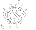
- FIG. 5 is a perspective view of the mirror element according to the embodiment as viewed from the positive direction of the Z axis.
- FIG. 6 is a perspective view of the mirror element according to the embodiment as viewed from the negative Z-axis direction.
- FIG. 1 is a schematic cross-sectional view showing a schematic configuration of a lighting device according to an embodiment.
- FIG. 2 is a cross-sectional view showing a mirror device according to the embodiment.
- FIG. 3 is a perspective view of the reflecting section according to the embodiment as viewed from the positive direction of the Z
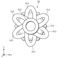
- FIG. 7 is a plan view of the mirror element according to the embodiment as viewed from the positive direction of the Z axis.
- FIG. 8 is a side view of the mirror element according to the embodiment as viewed in the negative Y-axis direction.
- FIG. 9 is a plan view of the coupled state of mirror elements according to the embodiment, as viewed from the positive direction of the Z axis.
- FIG. 10 is a side view of the coupled state of mirror elements according to the embodiment, as viewed from the negative Y-axis direction.
- FIG. 11 is a cross-sectional view showing a modified mirror device according to the embodiment.
- FIG. 12 is a plan view showing a reflecting portion and a deforming portion according to the first modification.
- FIG. 13 is a perspective view showing a reflecting portion according to the first modification.
- FIG. 12 is a plan view showing a reflecting portion and a deforming portion according to the first modification.
- FIG. 14 is a plan view showing a reflecting portion and a deforming portion according to the second modification.
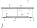
- FIG. 15 is a side view showing a deformation portion according to the third modification.
- FIG. 16 is a side view showing a deformation portion according to the third modification.
- FIG. 17 is a perspective view showing a reflecting portion according to the fourth modification.
- FIG. 18 is a cross-sectional view showing an assembly according to the fifth modification.
- Fig. 1 is a schematic cross-sectional view showing a schematic configuration of an illumination device 10 according to an embodiment.
- the illumination device 10 includes a housing 20, a light-emitting unit 30, a mirror device 40, a deformation unit 60, and a diffusion unit 70.
- the housing 20 is a long box body, and contains the light-emitting unit 30, the mirror device 40, and the diffusion unit 70.
- An opening 21 through which illumination light is emitted is formed in a portion of the housing 20 facing the mirror device 40.
- the opening 21 may be a simple opening, or may be covered with a light-transmitting member.
- the light-emitting unit 30 includes a heat sink 31, a light source 32, a first lens 33, a mirror pipe 34, a wavelength conversion element 35, and a second lens 36.
- the heat sink 31, the light source 32, the first lens 33, the mirror pipe 34, the wavelength conversion element 35, and the second lens 36 are arranged in this order from one end to the other end in the longitudinal direction of the housing 20.
- the heat sink 31 is attached to one end of the housing 20 in the longitudinal direction, and has a base 311 and a number of fins 312 protruding from the base 311.
- the base 311 is disposed inside the housing 20, and supports the light source 32.
- the multiple fins 312 protrude outward from the housing 20. This allows heat transferred from the light source 32 to the base 311 to be released to the outside of the housing 20 via the multiple fins 312.
- the light source 32 is a laser element that generates laser light whose emission peak wavelength is included in the blue wavelength band. In this embodiment, the case where two light sources 32 are provided is illustrated, but the number of light sources 32 provided may be one or three or more.
- the light source 32 is fixed to the base portion 311 of the heat sink 31 in a position in which it irradiates laser light toward the other end of the housing 20 in the longitudinal direction.
- the light source 32 may be an LED.
- the first lens 33 is a focusing lens that focuses the laser light emitted from the light source 32.
- the first lens 33 is disposed in a position facing the light source 32.
- the mirror pipe 34 is an optical component that guides the laser light focused by the first lens 33 to the wavelength conversion element 35.
- the mirror pipe 34 is a cylinder with both ends open, and the laser light is reflected on its inner surface.
- the mirror pipe 34 is arranged with its axial direction aligned with the longitudinal direction of the housing 20. The laser light received at one end of the mirror pipe 34 is reflected on the inner surface of the mirror pipe 34 and travels toward the other end of the mirror pipe 34.
- the wavelength conversion element 35 is an element that converts at least a portion of the laser light emitted from the other end of the mirror pipe 34 into light of a different wavelength band. Specifically, the wavelength conversion element 35 is arranged to cover the other end of the mirror pipe 34.
- the wavelength conversion element 35 includes a substrate 351 and a fluorescent section 352.
- the substrate 351 is a plate that holds the fluorescent section 352.
- the substrate 351 is formed from a light-transmitting material such as glass or sapphire.
- the fluorescent section 352 is layered on this substrate 351.
- the fluorescent part 352 has a plurality of dispersed particles of phosphor that are excited by the laser light emitted from the other end of the mirror pipe 34 and transmitted through the substrate 351 to emit fluorescence, and the phosphor emits fluorescence when irradiated with the laser light.
- the fluorescent part 352 can be a material in which phosphor particles are dispersed inside a base material made of transparent resin or glass, or a material in which phosphor particles are solidified.
- the fluorescent part 352 emits white light. That is, the fluorescent part 352 converts the laser light into light of a longer wavelength band.
- the type and characteristics of the phosphor are not particularly limited, but since a relatively high-output laser light is used as the excitation light, it is desirable that the phosphor has high heat resistance and does not cause brightness saturation.
- a relatively high-output laser light is used as the excitation light, it is desirable that the phosphor has high heat resistance and does not cause brightness saturation.
- YAG yttrium aluminum garnet
- the type of base material that holds the phosphor in a dispersed state is not particularly limited, but if the transparency is high, it is good because the yellow light emission efficiency is also high.
- a relatively high-output laser light is incident, a material with high heat resistance is good.
- the second lens 36 is a collimating lens that converts the light wavelength-converted by the wavelength conversion element 35 into parallel light.
- the second lens 36 is disposed in a position opposite the wavelength conversion element 35.
- the mirror device 40 is a part that reflects the light emitted by the light emitting unit 30, i.e., the light whose wavelength has been converted by the wavelength conversion element 35, toward the opening 21 of the housing 20. Specifically, the mirror device 40 is disposed at the other end of the housing 20 in the longitudinal direction.
- FIG. 2 is a cross-sectional view showing a mirror device 40 according to an embodiment.
- the Z-axis direction is the movement direction of a deformation section 60 provided in the mirror device 40
- the X-axis direction and the Y-axis direction are directions perpendicular to each other in a plane perpendicular to the Z-axis direction.
- the mirror device 40 has a freely deformable reflecting section 50 and a deformation section 60 that deforms the reflecting section 50.
- FIG. 3 is a perspective view of the reflecting unit 50 according to the embodiment, as viewed from the positive direction of the Z axis.
- FIG. 4 is a perspective view of the reflecting unit 50 according to the embodiment, as viewed from the negative direction of the Z axis.
- the reflecting unit 50 has a plurality of mirror elements 51 and a support unit 52 that supports the plurality of mirror elements 51.
- the multiple mirror elements 51 are connected to each other with adjacent mirror elements 51, forming a freely deformable assembly 54.
- the assembly 54 is formed in a hexagonal shape when viewed from above, with one end of an elastic member 53 connected to the mirror element 51 forming each corner.
- Each elastic member 53 is a coil spring, and the other end is connected to the support portion 52.
- the elastic member 53 connects at least one of the multiple mirror elements 51 to the support portion 52. Note that the elastic member 53 is not limited to a coil spring, and may be another type of spring or rubber, etc.
- Fig. 5 is a perspective view of the mirror element 51 according to the embodiment, as viewed from the positive direction of the Z axis.
- Fig. 6 is a perspective view of the mirror element 51 according to the embodiment, as viewed from the negative direction of the Z axis.
- Fig. 7 is a plan view of the mirror element 51 according to the embodiment, as viewed from the positive direction of the Z axis.
- Fig. 8 is a side view of the mirror element 51 according to the embodiment, as viewed from the negative direction of the Y axis.
- the mirror element 51 has a mirror portion 511, an axis portion 512, and a plurality of connecting portions 513.
- the mirror portion 511 is formed in a substantially hexagonal truncated pyramid shape, and the surface facing the negative Z-axis direction is the reflective surface 514.
- the reflective surface 514 reflects the light emitted by the light-emitting portion 30.
- the reflective surface 514 is formed in a hexagonal shape in a planar view. Note that the reflective surface 514 does not have to be planar, and is not limited to a hexagonal shape in a planar view.
- the shaft portion 512 is disposed in the center of the mirror portion 511 when viewed in the positive Z-axis direction.
- the shaft portion 512 extends in the positive Z-axis direction from the end of the mirror portion 511 in the positive Z-axis direction.
- the shaft portion 512 extends in the normal direction of the reflecting surface 514 (Z-axis direction) from the side opposite the reflecting surface 514 of the mirror portion 511.
- the shaft portion 512 is formed in a cylindrical shape with the end in the positive Z-axis direction open.
- the multiple connecting portions 513 are arranged at equal intervals in the circumferential direction of the shaft portion 512.
- Each connecting portion 513 is a curved rod-shaped portion that protrudes outward from the shaft portion 512 when viewed in the Z-axis direction.
- the axial cross-sectional shape of each connecting portion 513 is approximately circular.
- Each connecting portion 513 also protrudes from the mirror portion 511.
- Each connecting portion 513 is provided for one side of the reflecting surface 514. As described above, in this embodiment, the shape of the reflecting surface 514 in a plan view is hexagonal, so six connecting portions 513 are provided.
- Each connecting portion 513 only protrudes from one side of the reflecting surface 514 and does not interfere with the other sides.
- Each connecting portion 513 has one end connected to the end of the shaft portion 512 in the positive Z-axis direction, and the other end connected to the side of the mirror portion 511.
- one end of the connecting portion 513 is positioned at a position shifted in the clockwise direction from the other end when viewed in the Z-axis direction (see FIG. 7).
- the other end of one connecting portion 513 arranged in the clockwise direction is positioned at approximately the same position as one end of the other connecting portion 513 arranged in the counterclockwise direction when viewed in the Z-axis direction (see FIG. 7).
- each connecting portion 513 is inclined at a predetermined angle ⁇ with respect to the shaft portion 512 when viewed from a direction perpendicular to the normal direction (Z-axis direction) of the reflecting surface 514 (see FIG. 8).
- the direction perpendicular to the normal direction of the reflecting surface 514 is the direction in which the projected area of the target connecting portion 513 is smallest.
- the specified angle ⁇ is preferably in the range of greater than 0 degrees and less than or equal to 45 degrees, and more preferably in the range of greater than or equal to 10 degrees and less than or equal to 35 degrees.
- FIG. 9 is a plan view of the connection between mirror elements 51 according to the embodiment, as viewed from the positive direction of the Z axis.
- FIG. 10 is a side view of the connection between mirror elements 51 according to the embodiment, as viewed from the negative direction of the Y axis.
- the other mirror elements 51 that make up the assembly 54 are connected in the same manner.
- two adjacent mirror elements 51 are arranged so that one side of the reflective surfaces 514 is adjacent to each other.
- the connecting portions 513 corresponding to these one sides are connected to each other.
- one connecting portion 513 is arranged in the space formed by the other connecting portion 513 and penetrates through it.
- This state can also be said to be one connecting portion 513 arranged in the space formed by the other connecting portion 513 and penetrating it. Since the connecting portions 513 inclined with respect to the shaft portion 512 when viewed from a direction perpendicular to the Z-axis direction are connected to each other, it is possible to smoothly deform the assembly 54 while suppressing the gap (non-reflective area) between the reflective surfaces 514.
- the mirror elements 51 are manufactured by a 3D printer. In other words, by manufacturing all of the mirror elements 51 constituting the assembly 54 at once by a 3D printer, it is possible to combine the respective connecting parts 513.
- the mirror elements 51 may be made of resin or metal.
- at least one of polishing the entire assembly and coating it with fluororesin may be performed. Note that these treatments may be performed only on the connecting parts 513. It is possible to make the surface of the mirror part 511 in the negative Z-axis direction the reflective surface 514 as it is after manufacturing by the 3D printer, but the reflective performance of the reflective surface 514 may be improved by performing a mirror finish on the surface or laminating a reflective layer on the surface.
- the support section 52 is a circular plate-shaped frame, and an assembly 54 of multiple mirror elements 51 is arranged inside it.
- the support section 52 supports the assembly 54 via multiple elastic members 53.
- the elastic members 53 pull on the assembly 54, so that the surface of the assembly 54 in the negative Z-axis direction (each reflecting surface 514) becomes flat overall (see Figure 2).
- the deformation section 60 has an axis 61, a guide section 62 that holds the axis 61 so that it can slide freely, and a number of wires 63 that connect the guide section 62 to the support section 52.
- the shaft body 61 is a cylindrical rod extending in the Z-axis direction and is movable in the Z-axis direction.
- the shaft body 61 may be driven manually or by power from a drive source.
- the amount of movement of the shaft body 61 may be adjusted based on the control of a control unit.
- the drive source include a motor and a solenoid.
- the control unit include a microcomputer.
- the guide portion 62 is a cylinder extending in the Z-axis direction.
- the shaft body 61 penetrates the guide portion 62 in the Z-axis direction. This allows the guide portion 62 to guide the sliding movement of the shaft body 61 in the Z-axis direction.
- the shaft body 61 and the guide portion 62 are an example of a sliding mechanism.
- the guide portion 62 is fixed to a predetermined position by a fixing device (not shown).
- the multiple wires 63 are arranged at equal intervals in the circumferential direction when viewed in the Z-axis direction. One end of each wire 63 is connected to the guide portion 62, and the other end is connected to the support portion 52.
- FIG. 11 is a cross-sectional view showing the mirror device 40 after deformation according to the embodiment.
- the assembly 54 after deformation has each reflective surface 514 that is spherical overall.
- the connecting portions 513 of two adjacent mirror elements 51 are connected to each other, so the gap (non-reflective area) between the reflective surfaces 514 can be made as small as possible.
- the diffusion section 70 is a diffusion plate that diffuses the light reflected by the mirror device 40.
- the diffusion section 70 is disposed between the opening 21 of the housing 20 and the mirror device 40. The light reflected by each mirror element 51 is diffused by the diffusion section 70, thereby suppressing the graininess.
- the first light distribution pattern of the light reflected by the mirror device 40 is circular.
- the second light distribution pattern of the light reflected by the mirror device 40 becomes a circle that is larger than the first light distribution pattern.
- each reflecting surface 514 can be deformed into a wider variety of shapes, and accordingly, a wider variety of light distribution patterns can be produced.
- Other shapes include, for example, cylindrical surfaces, conical surfaces, and free-form surfaces.
- the curvature can be adjusted by adjusting the amount of movement of the shaft bodies 61.
- the mirror device 40 in this embodiment comprises a freely deformable reflective section 50 and a deformation section 60 that deforms the reflective section 50.
- the reflective section 50 has a plurality of mirror elements 51 connected to each other.
- the mirror element 51 comprises a mirror section 511 having a reflective surface 514, an axis section 512 extending in the normal direction (Z-axis direction) of the reflective surface 514 from the opposite side of the reflective surface 514 of the mirror section 511, and a connecting section 513 that protrudes outward from the axis section 512 when viewed from the normal direction so as to be inclined at a predetermined angle ⁇ relative to the axis section 512 when viewed from a direction perpendicular to the normal direction, and the connecting section 513 is connected to the connecting section 513 of another mirror element 51.
- the lighting device 10 also includes the mirror device 40 and a light-emitting unit 30 that emits light toward the multiple mirror elements 51 of the mirror device 40.
- two adjacent mirror elements 51 are connected by connecting portions 513 that are inclined relative to the axis portions 512 when viewed from a direction perpendicular to the normal direction of the reflecting surfaces 514, making it possible to smoothly deform the assembly 54 while suppressing gaps (non-reflective regions) between the reflecting surfaces 514. Since the non-reflective regions can be suppressed in this way, a decrease in reflection efficiency can be suppressed.
- the sliding mechanism (shaft 61 and guide 62) of the deformation section 60 slides to deform the reflecting section 50, so the deformation section 60 can be deformed with a relatively simple structure.
- the overall shape of each reflecting surface 514 can be deformed in a variety of ways.
- the elastic member 53 connects the support portion 52 to at least one mirror element 51 of the assembly 54, so that the elastic force of the elastic member can improve the reproducibility of the shape of the assembly 54.
- the deformation section 60 including a slide mechanism is exemplified.
- the deformation section may have any shape as long as it deforms the reflective section.
- FIG. 12 is a plan view showing the reflective section 50a and the deformation section 60a according to the first modification.
- FIG. 13 is a perspective view showing the reflective section 50a according to the first modification.
- the connecting parts 55a are attached to the mirror elements 51a that form each corner of the assembly 54a.
- the connecting parts 55a are disposed on the shaft parts 512a of each mirror element 51a, and are hooks that protrude from the shaft parts 512a in the positive direction of the Z axis.
- the deformation portion 60 has one wire 65a.
- This wire 65a is inserted through each connection portion 55a.
- the wire 65a is hexagonal in shape, and both ends are pulled outward from one connection portion 55a. By pulling out both ends of the wire 65a further, the assembly 54a is closed in a purse-like shape, and each reflection surface 514 becomes spherical.
- wire 65a is connected between at least two mirror elements 51a in this manner, it is possible to smoothly deform the assembly 54a by moving the wire 65a.
- the mirror element 51a is provided with a connection portion 55a to which the wire 65a is connected, so the wire 65a can be smoothly attached to the mirror element 51a via the connection portion 55a.
- FIG. 14 is a plan view showing the reflecting portion 50a and the deforming portion 60b according to the second modification.
- the deforming portion 60b has a plurality of wires 65b.
- Each wire 65b is bridged between the connecting portions 55a arranged at a pair of diagonal corners of the assembly 54a.
- the assembly 54a is closed in a purse-like shape, and each reflecting surface 514 becomes spherical.
- FIGS. 15 and 16 are side views showing the deformation portion 60c according to the third modified example. As shown in FIGS. 15 and 16, the deformation portion 60c has a fixing portion 66c and a guide portion 67c in addition to the wire 65a.
- the fixing portion 66c is a portion that fixes the position of a portion of the reflecting portion 50a. Specifically, the fixing portion 66c is disposed in the positive direction of the Z axis from the center of the assembly 54a in order to fix the position of the center of the assembly 54a when viewed in the Z axis direction.
- the fixing portion 66c is a support that extends in the Z axis direction, with one end of the support being in contact with the center of the assembly 54a and the other end being fixed to the guide portion 67c.
- the guide section 67c has a base 671c to which the other end of the fixed section 66c is fixed, and multiple guide shafts 672c protruding from the base 671c.
- the base 671c is a flat plate parallel to the XY plane, and each guide shaft 672c protrudes from its end in the negative Z direction.
- Each guide shaft 672c is an axle that extends in the Z direction, and slidably passes through the support section 52a of the reflector 50a.
- the support portion 52a moves in the positive direction of the Z axis while the fixing portion 66c holds down the center of the assembly 54a.
- This movement of the support portion 52a is guided by each guide shaft 672c of the guide portion 67c, allowing for stable movement.
- the peripheral portion of the assembly 54a also moves in the positive direction of the Z axis, resulting in smooth deformation of the assembly 54a.
- the support portion 52a and the assembly 54a are connected by the elastic member 53, so the posture of the assembly 54a is also stable.
- the guide portion 67c guides the movement of the support portion 52a while the fixing portion 66c holds down the center of the assembly 54a, so that the assembly 54a can be deformed stably.
- FIG 17 is a perspective view showing a reflecting section 50d according to variant example 4.
- the reflecting section 50d is provided with a frame material 59d that supports the assembly 54.
- the frame material 59d is attached to the assembly 54 by being placed on the surface of the assembly 54 in the positive Z-axis direction, i.e., the side opposite the mirror sections 511.
- the frame material 59d is a leaf spring, and has multiple beams 591d extending from the center of the assembly 54 so as to connect each corner of the assembly 54.
- the assembly 54 can be evenly deformed via the frame material 59d.
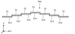
- FIG. 18 is a cross-sectional view showing an assembly 54e relating to variant example 5. As shown in FIG. 18, in assembly 54e, two adjacent mirror elements 51 overlap each other when viewed in the Z-axis direction.
- the planar shape of the reflecting surface 514 of each mirror element 51 is hexagonal.
- the planar shape of the reflecting surface may be another polygon, or may be a circle, an ellipse, an oval, or the like. This also applies to the assembly.
- the diffusing section 70 is a diffusing plate arranged in a position facing the mirror device 40.
- the diffusing section may be arranged in any location as long as it can diffuse the light reflected by the reflecting section.
- the diffusing section may be laminated on the reflecting surface of each mirror element.
- the light source 32 is a laser element or an LED.
- other light sources may be used. Examples of other light sources include incandescent light bulbs, halogen light bulbs, and fluorescent lights.
- each reflecting surface 514 of the assembly 54 is deformed from a flat surface to a convex curved surface as a whole is illustrated.
- the present invention also includes forms obtained by applying various modifications to the embodiments that a person skilled in the art may conceive, and forms realized by arbitrarily combining the components and functions of each embodiment within the scope of the spirit of the present invention.
- the lighting device according to the present invention is not limited to the following examples.
- the mirror device of Technology 1 includes a freely deformable reflecting section and a deforming section that deforms the reflecting section, the reflecting section includes a plurality of mirror elements connected to each other, and the mirror elements include a mirror section having a reflecting surface, an axis section that extends in a normal direction to the reflecting surface from the opposite side of the reflecting surface of the mirror section, and a connecting section that protrudes outward from the axis section when viewed from the normal direction so as to be inclined at a predetermined angle to the axis section when viewed from a direction perpendicular to the normal direction, and that is connected to a connecting section of another mirror element.
- Technology 2 is a mirror device according to Technology 1, in which the deformation section includes a sliding mechanism that deforms the reflection section by sliding.
- Technology 3 is a mirror device according to Technology 1 or Technology 2, in which the deformation section includes a wire connecting at least two of the multiple mirror elements.
- Technology 4 is a mirror device according to Technology 3, in which the mirror element is disposed on the shaft portion and has a connection portion to which the wire is connected.
- Technology 5 is a mirror device according to any one of Technology 1 to Technology 4, which includes a support section that supports the reflecting section, and an elastic member that connects at least one of the multiple mirror elements to the support section.
- Technology 6 provides the mirror device described in Technology 5 with a fixing section that fixes the position of a portion of the reflecting section relative to the support section, and a guide section that guides the movement of the support section.
- Technology 7 is a mirror device according to any one of Technology 1 to Technology 6, in which the mirror portions of two adjacent mirror elements among the plurality of mirror elements overlap when viewed from the normal direction.
- Technology 8 is a mirror device according to any one of Technology 1 to Technology 7, which has a frame material that supports the multiple mirror elements by stacking them from the side opposite the mirror portion.
- the lighting device of Technology 9 includes a mirror device according to any one of Technology 1 to Technology 8, and a light-emitting unit that emits light toward the multiple mirror elements of the mirror device.
- Reference Signs List 10 Illumination device 30 Light-emitting section 40
- Shaft body 62 Guide section 63 Wire material 65a, 65b Wire 66c Fixation section 67c Guide section 511 Mirror section 512, 512a Shaft section 513 Connection section 514 Reflection surface 672c Guide axis ⁇ Predetermined angle
Landscapes
- Physics & Mathematics (AREA)
- General Physics & Mathematics (AREA)
- Optics & Photonics (AREA)
- Engineering & Computer Science (AREA)
- General Engineering & Computer Science (AREA)
- Non-Portable Lighting Devices Or Systems Thereof (AREA)
Abstract
ミラー装置(40)は、変形自在な反射部(50)と、反射部を変形させる変形部(60)とを備えている。反射部は、互いに連結された複数のミラー素子(51)を有している。ミラー素子は、反射面(514)を有するミラー部(511)と、ミラー部の反射面とは反対側から当該反射面の法線方向(Z軸方向)に延びる軸部(512)と、法線方向に直交する方向から見て軸部に対して所定角度(α)傾斜するように、法線方向から見て軸部の外方に突出した連結部(513)であって、他のミラー素子の連結部に連結される連結部とを備える。
Description
本発明は、ミラー装置及び照明装置に関する。
従来、複数のミラーを平面的に連結し、各ミラーエレメントを変動させることで、光の向きを制御できるミラー装置が知られている(例えば特許文献1参照)。
ところで、特許文献1に記載のミラー装置であると、各ミラーエレメントがリンキング部材で連結されているが、リンキング部材の長さ分、隙間を発生させてしまう。この隙間では、光を反射できないため、反射効率が低下してしまうおそれがある。
本発明の目的は、反射効率の低下を抑制できるミラー装置などを提供することである。
本発明の一態様に係るミラー装置は、変形自在な反射部と、前記反射部を変形させる変形部とを備え、前記反射部は、互いに連結された複数のミラー素子を有し、前記ミラー素子は、反射面を有するミラー部と、前記ミラー部の前記反射面とは反対側から当該反射面の法線方向に延びる軸部と、前記法線方向に直交する方向から見て前記軸部に対して所定角度で傾斜するように、前記法線方向から見て前記軸部の外方に突出した連結部であって、他のミラー素子の連結部に連結される連結部とを備える。
本発明の他の態様に係る照明装置は、上記ミラー装置と、前記ミラー装置の前記複数のミラー素子に向けて光を出射する発光部とを備える。
本発明によれば、反射効率の低下を抑制できるミラー装置などを提供できる。
以下では、本発明の実施の形態に係る照明装置及びミラー装置について、図面を用いて説明する。なお、以下に説明する実施の形態は、いずれも本発明の好ましい一具体例を示すものである。従って、以下の実施の形態で示される数値、形状、材料、構成要素、構成要素の配置及び接続形態等は、一例であり、本発明を限定する趣旨ではない。よって、以下の実施の形態における構成要素のうち、本発明の最上位概念を示す独立請求項に記載されていない構成要素については、任意の構成要素として説明される。また、各図は、模式図であり、必ずしも厳密に図示されたものではない。また、各図において、同じ構成部材については同じ符号を付している。
[実施の形態]
以下、実施の形態について説明する。図1は、実施の形態に係る照明装置10の概略構成を示す模式断面図である。図1に示すように、照明装置10は、筐体20と、発光部30と、ミラー装置40と、変形部60と、拡散部70とを備えている。筐体20は、長尺な箱体であり、発光部30と、ミラー装置40と、拡散部70とを収容している。筐体20においてミラー装置40に対向する部位には、照明光が出射される開口部21が形成されている。開口部21は、単なる開口であってもよいし、透光部材で覆われていてもよい。
以下、実施の形態について説明する。図1は、実施の形態に係る照明装置10の概略構成を示す模式断面図である。図1に示すように、照明装置10は、筐体20と、発光部30と、ミラー装置40と、変形部60と、拡散部70とを備えている。筐体20は、長尺な箱体であり、発光部30と、ミラー装置40と、拡散部70とを収容している。筐体20においてミラー装置40に対向する部位には、照明光が出射される開口部21が形成されている。開口部21は、単なる開口であってもよいし、透光部材で覆われていてもよい。
発光部30は、ヒートシンク31と、光源32と、第一レンズ33と、ミラーパイプ34と、波長変換素子35と、第二レンズ36とを備えている。ヒートシンク31と、光源32と、第一レンズ33と、ミラーパイプ34と、波長変換素子35と、第二レンズ36とは、筐体20の長手方向の一端部から他端部に向けてこの順で並んでいる。
ヒートシンク31は、筐体20の長手方向の一端部に取り付けられており、台座部311と、当該台座部311から突出した複数のフィン312とを有している。台座部311は、筐体20の内方に配置されており、光源32を支持している。複数のフィン312は、筐体20から外方に突出している。これにより、光源32から台座部311に伝わった熱が、複数のフィン312を介して筐体20の外方へ放出されるようになっている。
光源32は、発光ピーク波長が青色波長帯域に含まれるレーザ光を発生させるレーザ素子である。本実施の形態では、光源32は、2つ設けられている場合を例示しているが光源32の設置個数は1つであっても3つ以上であってもよい。光源32は、筐体20の長手方向の他端部に向けてレーザ光を照射する姿勢でヒートシンク31の台座部311に固定されている。光源32は、LEDであってもよい。
第一レンズ33は、光源32から照射されたレーザ光を集光する集光レンズである。第一レンズ33は、光源32に対向する位置に配置されている。
ミラーパイプ34は、第一レンズ33で集光されたレーザ光を波長変換素子35まで導く光学部材である。具体的には、ミラーパイプ34は、両端が開放された筒体であり、その内面でレーザ光が反射される。ミラーパイプ34は、軸方向が筐体20の長手方向に沿う姿勢で配置されている。ミラーパイプ34の一端部で受け入れられたレーザ光は、ミラーパイプ34の内面で反射されながら、ミラーパイプ34の他端部に向かう。
波長変換素子35は、ミラーパイプ34の他端部から出射したレーザ光の少なくとも一部を、異なる波長帯の光に変換する素子である。具体的には、波長変換素子35は、ミラーパイプ34の他端部を覆うように配置されている。波長変換素子35は、基板351と蛍光部352とを備えている。基板351は、蛍光部352を保持する板体である。基板351は、例えばガラス、サファイアなどの透光性材料から形成されている。この基板351に蛍光部352が積層されている。
蛍光部352は、ミラーパイプ34の他端部から出射し、基板351を透過したレーザ光によって励起されて蛍光を発する複数の蛍光体の粒子を分散状態で備えており、レーザ光の照射により蛍光体が蛍光を発する。具体的に、蛍光部352は、透明な樹脂やガラスからなる基材の内部に蛍光体の粒子が分散されているもの、または、蛍光体の粒子を固めたもの等を例示できる。本実施の形態の場合、蛍光部352は白色光を放射するものである。つまり、蛍光部352は、レーザ光をより長い波長帯の光に変換する。蛍光体の種類及び特性は特に限定されるものではないが、比較的高い出力のレーザ光が励起光となるため、熱耐性が高く、輝度飽和が発生しないものが望ましい。例えば、イットリウム・アルミニウム・ガーネット(YAG)系の蛍光体が採用される。蛍光体を分散状態で保持する基材の種類は特に限定されるものではないが、透明性が高ければ、黄色光の放射効率も高くなるのでよい。また、比較的高い出力のレーザ光が入射するため、耐熱性の高いものがよい。
第二レンズ36は、波長変換素子35で波長変換された光を平行光に変換するコリメートレンズである。第二レンズ36は、波長変換素子35に対向する位置に配置されている。
ミラー装置40は、発光部30が発した光、つまり、波長変換素子35で波長変換された光を、筐体20の開口部21に向けて反射する部位である。具体的には、ミラー装置40は、筐体20の長手方向の他端部に配置されている。
図2は、実施の形態に係るミラー装置40を示す断面図である。ここで、Z軸方向は、ミラー装置40に備わる変形部60の移動方向であり、X軸方向及びY軸方向は、Z軸方向に直交する平面内で互いに直交する方向である。図2に示すように、ミラー装置40は、変形自在な反射部50と、反射部50を変形させる変形部60とを備えている。
図3は、実施の形態に係る反射部50をZ軸プラス方向から見た斜視図である。図4は、実施の形態に係る反射部50をZ軸マイナス方向から見た斜視図である。図3及び図4に示すように、反射部50は、複数のミラー素子51と、複数のミラー素子51を支持する支持部52とを有している。
複数のミラー素子51は、隣り合うミラー素子51同士が互いに連結されて、変形自在な集合体54をなしている。集合体54は、平面視六角形状に形成されており、各角部をなすミラー素子51に弾性部材53の一端部が接続されている。各弾性部材53は、コイルバネであり、他端部が支持部52に接続されている。弾性部材53は、複数のミラー素子51のうち、少なくとも1つのミラー素子51と、支持部52とを繋いでいる。なお、弾性部材53は、コイルバネに限定されるものではなく、他のバネまたはゴムなどであってもよい。
次に、ミラー素子51について詳細に説明する。図5は、実施の形態に係るミラー素子51をZ軸プラス方向から見た斜視図である。図6は、実施の形態に係るミラー素子51をZ軸マイナス方向から見た斜視図である。図7は、実施の形態に係るミラー素子51をZ軸プラス方向から見た平面図である。図8は、実施の形態に係るミラー素子51をY軸マイナス方向から見た側面図である。
図5~図6に示すように、ミラー素子51は、ミラー部511と、軸部512と、複数の連結部513とを有している。ミラー部511は、略六角錐台状に形成された部位であり、Z軸マイナス方向の面が反射面514となっている。反射面514は、発光部30が発した光を反射する。反射面514は、平面視六角形状に形成されている。なお、反射面514は、平面状でなくても、平面視六角形状に限定されない。
軸部512は、Z軸プラス方向視でミラー部511の中央部に配置されている。軸部512は、ミラー部511のZ軸プラス方向の端部から、Z軸プラス方向に延びている。つまり、軸部512は、ミラー部511の反射面514とは反対側から当該反射面514の法線方向(Z軸方向)に延びている。軸部512は、Z軸プラス方向の端部が開放された円筒状に形成されている。
複数の連結部513は、軸部512の周方向に等間隔で配列されている。各連結部513は、Z軸方向視で軸部512の外方に向けて突出しており、湾曲した棒状部である。各連結部513の軸断面形状は略円形となっている。各連結部513は、ミラー部511からも突出している。各連結部513は、反射面514の一辺に対して1つ設けられている。上述したように、本実施の形態では、反射面514の平面視形状は六角形状であるので、連結部513は6つ設けられている。1つの連結部513は、反射面514の一辺から突出しているだけであり、他辺には干渉していない。
各連結部513は、一端部が軸部512のZ軸プラス方向の端部に接続され、他端部がミラー部511の側面に接続されている。1つの連結部513に着目すると、Z軸方向視では、連結部513の一端部が他端部よりも時計回り方向にずれた位置に配置されている(図7参照)。周方向で隣り合う2つの連結部513に着目すると、Z軸方向視では、時計回り方向に配置された一方の連結部513の他端部が、反時計回り方向に配置された他方の連結部513の一端部と概ね同じ位置に配置されている(図7参照)。このため、各連結部513は、反射面514の法線方向(Z軸方向)に直交する方向から見て軸部512に対して所定角度αで傾斜している(図8参照)。厳密には、反射面514の法線方向に直交する方向とは、対象となる連結部513の投影面積が最も小さくなる方向である。ここで、所定角度αは、0度より大きく45度以下の範囲に収まれば好ましく、10度以上35度以下の範囲に収まればより好ましい。
図9は、実施の形態に係るミラー素子51同士の連結状態をZ軸プラス方向から見た平面図である。図10は、実施の形態に係るミラー素子51同士の連結状態をY軸マイナス方向から見た側面図である。なお、集合体54をなす他のミラー素子51も同様に連結されている。
図9及び図10に示すように、隣り合う2つのミラー素子51は、反射面514の一辺同士が隣り合うように配置されている。これらの一辺に対応した連結部513同士が連結されている。具体的には、一方の連結部513がなす空間内に他方の連結部513が配置され貫通している。この状態は、他方の連結部513がなす空間内に一方の連結部513が配置され貫通しているとも言える。Z軸方向に直交する方向から見て軸部512に対して傾斜した連結部513同士が連結されているので、反射面514同士の隙間(非反射領域)を抑制しつつ、集合体54の変形をスムーズに行うことが可能である。
ここで、ミラー素子51は、3Dプリンタで製造されるものである。つまり、集合体54をなす全てのミラー素子51を3Dプリンタで一括して製造することで、各連結部513同士を組み合わせることが可能である。ミラー素子51は、樹脂製であっても金属製であってもよい。連結部513同士の摩擦を減らすため、集合体全体に研磨処理を施すこと、及びフッ素樹脂をコートすることの少なくとも一方を行ってもよい。なお、これらの処理は、連結部513のみに行われてもよい。3Dプリンタによる製造後の状態のままで、ミラー部511のZ軸マイナス方向の面を反射面514とすることも可能であるが、当該面に対して鏡面加工を施したり、反射層を積層したりすることで反射面514の反射性能を高めてもよい。
図2~図4に示すように、支持部52は、円環板状の枠体であり、その内方に複数のミラー素子51の集合体54が配置されている。支持部52は、複数の弾性部材53を介して集合体54を支持している。変形部60からの外力を集合体が受けない場合には、各弾性部材53が集合体54を引っ張り合うので、集合体54のZ軸マイナス方向の面(各反射面514)が全体として平坦状となる(図2参照)。
図2に示すように、変形部60は、軸体61と、軸体61をスライド自在に保持するガイド部62と、ガイド部62を支持部52に連結する複数の線材63とを有している。
軸体61は、Z軸方向に延びる円柱状の棒材であり、Z軸方向に移動自在となっている。ここで、軸体61は手動で駆動しても、駆動源からの動力で駆動してもよい。駆動源からの動力で駆動する場合には、制御部の制御に基づいて軸体61の移動量が調整されてもよい。駆動源としては例えばモータ、ソレノイド等が挙げられる。制御部としては例えばマイクロコンピュータ等が挙げられる。
ガイド部62は、Z軸方向に延びる円筒体である。ガイド部62には、軸体61がZ軸方向に貫通されている。これにより、軸体61のZ軸方向のスライド移動をガイド部62でガイドできるようになっている。つまり、軸体61及びガイド部62はスライド機構の一例である。ガイド部62は図示しない固定具で、所定の位置に固定されている。複数の線材63は、Z軸方向視で周方向に等間隔で配置されている。各線材63の一端部は、ガイド部62に連結されており、他端部は支持部52に連結されている。
このように変形部60が構成されているので、軸体61がZ軸マイナス方向にスライド移動すると、軸体61の先端部が集合体54の中央部のミラー素子51をZ軸マイナス方向に押す。これにより、集合体54が変形することになる。図11は、実施の形態に係る変形後のミラー装置40を示す断面図である。本実施の形態では、変形後の集合体54は、各反射面514が全体として球面状をなすようになっている。
変形後の集合体54であっても、隣り合う2つのミラー素子51の連結部513同士が連結されているので、反射面514同士の隙間(非反射領域)を極力小さくすることができる。
図1に示すように、拡散部70は、ミラー装置40で反射された光を拡散する拡散板である。拡散部70は、筐体20の開口部21とミラー装置40との間に配置されている。各ミラー素子51で反射された光は拡散部70で拡散されることで、粒感が抑制されることになる。
次に、ミラー装置40の変形を起因とした配光パターンの切り替えについて説明する。集合体54をなす各ミラー素子51の各反射面514が全体として平面状である場合には、ミラー装置40で反射された光の第一配光パターンは円形状となる。
変形部60によって集合体54が変形されて各反射面514が全体として球面状となった場合には、ミラー装置40で反射された光の第二配光パターンは、第一配光パターンよりも大型な円形状となる。
なお、変形部60において軸体61の設置箇所、設置個数を調整することでより多様な形状に各反射面514を変形させることもでき、これに応じて多様な配光パターンとすることも可能である。その他の形状としては、例えば、円筒面状、円錐面状、自由曲面状などが挙げられる。また、軸体61の移動量を調整することで曲率も調整可能である。
[効果など]
本実施の形態に係るミラー装置40は、変形自在な反射部50と、反射部50を変形させる変形部60とを備え、反射部50は、互いに連結された複数のミラー素子51を有し、ミラー素子51は、反射面514を有するミラー部511と、ミラー部511の反射面514とは反対側から当該反射面514の法線方向(Z軸方向)に延びる軸部512と、法線方向に直交する方向から見て軸部512に対して所定角度αで傾斜するように、法線方向から見て軸部512の外方に突出した連結部513であって、他のミラー素子51の連結部513に連結される連結部513と、を備える。
本実施の形態に係るミラー装置40は、変形自在な反射部50と、反射部50を変形させる変形部60とを備え、反射部50は、互いに連結された複数のミラー素子51を有し、ミラー素子51は、反射面514を有するミラー部511と、ミラー部511の反射面514とは反対側から当該反射面514の法線方向(Z軸方向)に延びる軸部512と、法線方向に直交する方向から見て軸部512に対して所定角度αで傾斜するように、法線方向から見て軸部512の外方に突出した連結部513であって、他のミラー素子51の連結部513に連結される連結部513と、を備える。
また、本実施の形態に係る照明装置10は、上記ミラー装置40と、ミラー装置40の複数のミラー素子51に向けて光を出射する発光部30とを備えている。
これらによれば、隣り合う2つのミラー素子51では、反射面514の法線方向に直交する方向から見て軸部512に対して傾斜した連結部513同士が連結されているので、反射面514同士の隙間(非反射領域)を抑制しつつ、集合体54の変形をスムーズに行うことが可能である。このように非反射領域を抑制できるので、反射効率の低下を抑制できる。
変形部60のスライド機構(軸体61及びガイド部62)がスライドすることで反射部50を変形させるので、比較的簡単な構造で変形部60を変形させることができる。また、軸体61の設置箇所、設置個数、移動量等を調整することで、各反射面514の全体的な形状を多様に変形できる。
弾性部材53が支持部52と集合体54の少なくとも1つのミラー素子51とを繋いでいるので、弾性部材の弾性力により、集合体54の形状の再現性を高めることが可能である。
[変形例]
以下、本開示に係るミラー装置の変形例について説明する。以降の説明において、上記実施の形態及び他の変形例と同等の部分については同等の符号を付し、その説明を省略する場合がある。
以下、本開示に係るミラー装置の変形例について説明する。以降の説明において、上記実施の形態及び他の変形例と同等の部分については同等の符号を付し、その説明を省略する場合がある。
上記実施の形態では、スライド機構を含む変形部60を例示した。しかしながら変形部は、反射部を変形させるのであればその形態は如何様でもよい。図12は、変形例1に係る反射部50a及び変形部60aを示す平面図である。図13は、変形例1に係る反射部50aを示す斜視図である。
図12及び図13に示すように、反射部50aでは、集合体54aの各角部をなすミラー素子51aに接続部55aが取り付けられている。具体的には、接続部55aは、各ミラー素子51aの軸部512aに配置されており、当該軸部512aからZ軸プラス方向に突出したフックである。
変形部60は、1つのワイヤー65aを有している。このワイヤー65aは、各接続部55aに対し挿通されている。ワイヤー65aは六角形状となっており、両端部が1つの接続部55aから外方に引き出されている。ワイヤー65aの両端部を更に引き出すことで、集合体54aが巾着状に閉ざされ、各反射面514が球面状となる。
このように少なくとも2つのミラー素子51a同士にワイヤー65aが連結されているので、ワイヤー65aを変動させることで集合体54aをスムーズに変形させることが可能である。
ミラー素子51aには、ワイヤー65aが接続される接続部55aが設けられているので、接続部55aを介することでスムーズにワイヤー65aをミラー素子51aに取り付けることが可能である。
図14は、変形例2に係る反射部50a及び変形部60bを示す平面図である。図14に示すように、変形部60bは、複数のワイヤー65bを有している。各ワイヤー65bは、集合体54aの対角をなす一対の角部に配置された接続部55a同士に架け渡されている。各ワイヤー65bの中央部を引き寄せ合うことで、集合体54aが巾着状に閉ざされ、各反射面514が球面状となる。
図15及び図16は、変形例3に係る変形部60cを示す側面図である。図15及び図16に示すように、変形部60cは、ワイヤー65aに加えて、固定部66c及びガイド部67cを有している。
固定部66cは、反射部50aの一部の位置を固定する部位である。具体的には、固定部66cは、集合体54aのZ軸方向視の中央部の位置を固定するため、当該中央部のZ軸プラス方向に配置されている。固定部66cは、Z軸方向に延びた支柱であり、その一端部が集合体54aの中央部に接触しており、他端部がガイド部67cに固定されている。
ガイド部67cは、固定部66cの他端部が固定される台671cと、台671cから突出した複数のガイド軸672cとを有している。台671cは、XY面に平行な平板であり、その端部から各ガイド軸672cがZ軸マイナス方向に突出している。各ガイド軸672cは、Z軸方向に延びる軸体であり、反射部50aの支持部52aをスライド自在に貫通している。
ワイヤー65aの両端部を引き出しつつ、反射部50aをZ軸プラス方向に移動させると、固定部66cが集合体54aの中央部を押さえたまま、支持部52aがZ軸プラス方向に移動する。この支持部52aを移動は、ガイド部67cの各ガイド軸672cでガイドされているので安定した移動が可能である。支持部52aが移動すると、集合体54aの周縁部もZ軸プラス方向に移動するので、集合体54aがスムーズに変形することになる。このとき、支持部52aと集合体54aとは、弾性部材53で繋がっているために、集合体54aの姿勢も安定する。
このように、固定部66cが集合体54aの中央部を押さえたまま、支持部52aの移動をガイド部67cがガイドするので、集合体54aを安定的に変形させることができる。
図17は、変形例4に係る反射部50dを示す斜視図である。図17に示すように、反射部50dには、集合体54を支持するフレーム材59dが設けられている。具体的には、フレーム材59dは、集合体54のZ軸プラス方向の面、つまり、各ミラー部511とは反対側から集合体54に重ねられて、集合体54に取り付けられている。フレーム材59dは、板バネであり、集合体54の各角部を結ぶように、集合体54の中央から延びる複数の梁部591dを有している。
このようにフレーム材59dが集合体54に重なっているので、フレーム材59dを介して集合体54を均等に変形させることができる。
図18は、変形例5に係る集合体54eを示す断面図である。図18に示すように、集合体54eは、隣り合う2つのミラー素子51がZ軸方向視で重なり合っている。
このように、隣り合う2つのミラー素子51がZ軸方向視で重なり合っているので、当該2つのミラー素子51の反射面514同士の隙間(非反射領域)を抑制できる。
[その他]
以上、本発明に係る照明装置について、上記実施の形態に基づいて説明したが、本発明は、上記の実施の形態に限定されるものではない。
以上、本発明に係る照明装置について、上記実施の形態に基づいて説明したが、本発明は、上記の実施の形態に限定されるものではない。
例えば、上記実施の形態では、各ミラー素子51の反射面514の平面視形状が六角形状である場合を例示した。しかしながら、反射面の平面視形状は他の多角形でもよいし、円形状、楕円形状、長円形状などであってもよい。これは集合体においても同様である。
上記実施の形態では、拡散部70がミラー装置40に対向する位置に配置された拡散板である場合を例示した。しかしながら、拡散部は反射部で反射された光を拡散できるのであれば如何なる箇所に配置されていてもよい。例えば、各ミラー素子の反射面に拡散部が積層されていてもよい。
また、上記実施の形態では、光源32がレーザ素子またはLEDである場合を例示した。しかしながら、他の光源を採用することも可能である。他の光源としては、例えば、白熱電球、ハロゲン電球、蛍光灯などが挙げられる。
また、上記実施の形態では、集合体54の各反射面514が全体として平面から凸曲面に変形される場合を例示した。しかしながら、集合体の各反射面が全体として凹曲面に変形させることも可能である。
その他、実施の形態に対して当業者が思いつく各種変形を施して得られる形態や、本発明の趣旨を逸脱しない範囲で各実施の形態における構成要素及び機能を任意に組み合わせることで実現される形態も本発明に含まれる。
以下に、上記実施の形態に基づいて説明した本発明に係る照明装置の例を示す。本発明に係る照明装置は、以下の例に限定されるものではない。
例えば、技術1のミラー装置は、変形自在な反射部と、前記反射部を変形させる変形部とを備え、前記反射部は、互いに連結された複数のミラー素子を有し、前記ミラー素子は、反射面を有するミラー部と、前記ミラー部の前記反射面とは反対側から当該反射面の法線方向に延びる軸部と、前記法線方向に直交する方向から見て前記軸部に対して所定角度で傾斜するように、前記法線方向から見て前記軸部の外方に突出した連結部であって、他のミラー素子の連結部に連結される連結部とを備える。
技術2は、技術1に記載のミラー装置において、前記変形部は、スライドすることで前記反射部を変形させるスライド機構を含む。
技術3は、技術1または技術2に記載のミラー装置において、前記変形部は、複数の前記ミラー素子のうち、少なくとも2つのミラー素子同士に連結されたワイヤーを含む。
技術4は、技術3に記載のミラー装置において、前記ミラー素子は、前記軸部に配置され、前記ワイヤーが接続される接続部を有する。
技術5は、技術1~技術4のいずれかひとつに記載のミラー装置において、前記反射部を支持する支持部と、複数の前記ミラー素子のうち、少なくとも1つのミラー素子と、前記支持部とを繋ぐ弾性部材とを備える。
技術6は、技術5に記載のミラー装置において、前記支持部に対する前記反射部の一部の位置を固定する固定部と、前記支持部の移動をガイドするガイド部とを備える。
技術7は、技術1~技術6のいずれかひとつに記載のミラー装置において、複数の前記ミラー素子のうち、隣り合う2つのミラー素子は、前記法線方向から見た場合に前記ミラー部同士が重なり合っている。
技術8は、技術1~技術7のいずれかひとつに記載のミラー装置において、複数の前記ミラー素子に対し、前記ミラー部とは反対側から重ねられて支持するフレーム材を有する。
技術9の照明装置は、技術1~技術8のいずれかひとつに記載のミラー装置と、前記ミラー装置の前記複数のミラー素子に向けて光を出射する発光部とを備える。
10 照明装置
30 発光部
40 ミラー装置
50、50a、50d 反射部
51、51a ミラー素子
52、52a 支持部
53 弾性部材
54、54a、54e 集合体
55a 接続部
59d フレーム材
60、60a、60b、60c 変形部
61 軸体
62 ガイド部
63 線材
65a、65b ワイヤー
66c 固定部
67c ガイド部
511 ミラー部
512、512a 軸部
513 連結部
514 反射面
672c ガイド軸
α 所定角度
30 発光部
40 ミラー装置
50、50a、50d 反射部
51、51a ミラー素子
52、52a 支持部
53 弾性部材
54、54a、54e 集合体
55a 接続部
59d フレーム材
60、60a、60b、60c 変形部
61 軸体
62 ガイド部
63 線材
65a、65b ワイヤー
66c 固定部
67c ガイド部
511 ミラー部
512、512a 軸部
513 連結部
514 反射面
672c ガイド軸
α 所定角度
Claims (9)
- 変形自在な反射部と、
前記反射部を変形させる変形部とを備え、
前記反射部は、互いに連結された複数のミラー素子を有し、
前記ミラー素子は、
反射面を有するミラー部と、
前記ミラー部の前記反射面とは反対側から当該反射面の法線方向に延びる軸部と、
前記法線方向に直交する方向から見て前記軸部に対して所定角度で傾斜するように、前記法線方向から見て前記軸部の外方に突出した連結部であって、他のミラー素子の連結部に連結される連結部とを備える、
ミラー装置。 - 前記変形部は、スライドすることで前記反射部を変形させるスライド機構を含む、
請求項1に記載のミラー装置。 - 前記変形部は、複数の前記ミラー素子のうち、少なくとも2つのミラー素子同士に連結されたワイヤーを含む、
請求項1に記載のミラー装置。 - 前記ミラー素子は、前記軸部に配置され、前記ワイヤーが接続される接続部を有する、
請求項3に記載のミラー装置。 - 前記反射部を支持する支持部と、
複数の前記ミラー素子のうち、少なくとも1つのミラー素子と、前記支持部とを繋ぐ弾性部材とを備える、
請求項1または2に記載のミラー装置。 - 前記支持部に対する前記反射部の一部の位置を固定する固定部と、
前記支持部の移動をガイドするガイド部とを備える、
請求項5に記載のミラー装置。 - 複数の前記ミラー素子のうち、隣り合う2つのミラー素子は、前記法線方向から見た場合に前記ミラー部同士が重なり合っている、
請求項1または2に記載のミラー装置。 - 複数の前記ミラー素子に対し、前記ミラー部とは反対側から重ねられて支持するフレーム材を有する、
請求項1または2に記載のミラー装置。 - 請求項1または2に記載のミラー装置と、
前記ミラー装置の前記複数のミラー素子に向けて光を出射する発光部とを備える、
照明装置。
Priority Applications (1)
| Application Number | Priority Date | Filing Date | Title |
|---|---|---|---|
| JP2025527540A JPWO2024257505A1 (ja) | 2023-06-13 | 2024-05-08 |
Applications Claiming Priority (2)
| Application Number | Priority Date | Filing Date | Title |
|---|---|---|---|
| JP2023-097276 | 2023-06-13 | ||
| JP2023097276 | 2023-06-13 |
Publications (1)
| Publication Number | Publication Date |
|---|---|
| WO2024257505A1 true WO2024257505A1 (ja) | 2024-12-19 |
Family
ID=93851971
Family Applications (1)
| Application Number | Title | Priority Date | Filing Date |
|---|---|---|---|
| PCT/JP2024/017037 Ceased WO2024257505A1 (ja) | 2023-06-13 | 2024-05-08 | ミラー装置及び照明装置 |
Country Status (2)
| Country | Link |
|---|---|
| JP (1) | JPWO2024257505A1 (ja) |
| WO (1) | WO2024257505A1 (ja) |
Citations (8)
| Publication number | Priority date | Publication date | Assignee | Title |
|---|---|---|---|---|
| JPS5635102A (en) * | 1979-08-03 | 1981-04-07 | Shikopa Sa Soc Intern Dou Cons | Pivotable parabolic reflector and producing same |
| WO2006006240A1 (ja) * | 2004-07-14 | 2006-01-19 | Mitsubishi Denki Kabushiki Kaisha | 反射鏡装置 |
| JP2009139761A (ja) * | 2007-12-07 | 2009-06-25 | Mitaka Koki Co Ltd | 太陽追尾集光装置 |
| JP2009151211A (ja) * | 2007-12-21 | 2009-07-09 | Mitsui Eng & Shipbuild Co Ltd | 取付姿勢測定装置 |
| JP2010160033A (ja) * | 2009-01-07 | 2010-07-22 | Denso Corp | ファブリペロー干渉計及びその製造方法 |
| JP2014160211A (ja) * | 2013-02-20 | 2014-09-04 | Canon Inc | ミラーユニットおよび画像取得装置 |
| JP2014203905A (ja) * | 2013-04-03 | 2014-10-27 | 株式会社ニコン | 照明方法及び装置、並びに露光方法及び装置 |
| JP2019003216A (ja) * | 2013-12-09 | 2019-01-10 | 株式会社ブイ・テクノロジー | 露光装置、露光方法 |
-
2024
- 2024-05-08 WO PCT/JP2024/017037 patent/WO2024257505A1/ja not_active Ceased
- 2024-05-08 JP JP2025527540A patent/JPWO2024257505A1/ja active Pending
Patent Citations (8)
| Publication number | Priority date | Publication date | Assignee | Title |
|---|---|---|---|---|
| JPS5635102A (en) * | 1979-08-03 | 1981-04-07 | Shikopa Sa Soc Intern Dou Cons | Pivotable parabolic reflector and producing same |
| WO2006006240A1 (ja) * | 2004-07-14 | 2006-01-19 | Mitsubishi Denki Kabushiki Kaisha | 反射鏡装置 |
| JP2009139761A (ja) * | 2007-12-07 | 2009-06-25 | Mitaka Koki Co Ltd | 太陽追尾集光装置 |
| JP2009151211A (ja) * | 2007-12-21 | 2009-07-09 | Mitsui Eng & Shipbuild Co Ltd | 取付姿勢測定装置 |
| JP2010160033A (ja) * | 2009-01-07 | 2010-07-22 | Denso Corp | ファブリペロー干渉計及びその製造方法 |
| JP2014160211A (ja) * | 2013-02-20 | 2014-09-04 | Canon Inc | ミラーユニットおよび画像取得装置 |
| JP2014203905A (ja) * | 2013-04-03 | 2014-10-27 | 株式会社ニコン | 照明方法及び装置、並びに露光方法及び装置 |
| JP2019003216A (ja) * | 2013-12-09 | 2019-01-10 | 株式会社ブイ・テクノロジー | 露光装置、露光方法 |
Also Published As
| Publication number | Publication date |
|---|---|
| JPWO2024257505A1 (ja) | 2024-12-19 |
Similar Documents
| Publication | Publication Date | Title |
|---|---|---|
| JP5711147B2 (ja) | Led、光ガイド及びリフレクタを備える光源 | |
| US9366410B2 (en) | Reverse total internal reflection features in linear profile for lighting applications | |
| JP6271216B2 (ja) | 発光ユニットおよび照明装置 | |
| JP2010500710A (ja) | 光源及び光ガイドを有すること照明装置 | |
| US11104265B2 (en) | Lighting device for a motor vehicle headlight | |
| JP6890287B2 (ja) | 照明器具 | |
| JP6473966B2 (ja) | 照明装置および移動体 | |
| CN108291702B (zh) | 光源装置、照明装置和车辆用灯具 | |
| WO2009040725A2 (en) | Laser-pumped lamp using a light guide with a pinhole in its entrance mirror | |
| WO2024257505A1 (ja) | ミラー装置及び照明装置 | |
| JP7304520B2 (ja) | 照明装置 | |
| JP2008053660A (ja) | 発光モジュール | |
| KR20120137719A (ko) | 등기구 | |
| JP2018037257A (ja) | 面光源装置および液晶表示装置 | |
| JP5419852B2 (ja) | 照明装置 | |
| JP6041082B2 (ja) | 照明装置 | |
| WO2024252849A1 (ja) | 照明装置 | |
| WO2016175214A1 (ja) | 照明装置及び光学部材 | |
| JP6443751B2 (ja) | 照明装置、照明システム及び移動体 | |
| JP7515107B2 (ja) | 照明器具 | |
| JP2014203604A (ja) | 照明装置 | |
| CN107940268B (zh) | 激光模组及激光照明灯 | |
| JP2012199055A (ja) | 発光装置 | |
| JP2022099124A (ja) | 光学レンズ及び照明装置 | |
| JP7046305B2 (ja) | 光学装置および照明装置 |
Legal Events
| Date | Code | Title | Description |
|---|---|---|---|
| 121 | Ep: the epo has been informed by wipo that ep was designated in this application |
Ref document number: 24823127 Country of ref document: EP Kind code of ref document: A1 |
|
| ENP | Entry into the national phase |
Ref document number: 2025527540 Country of ref document: JP Kind code of ref document: A |
|
| WWE | Wipo information: entry into national phase |
Ref document number: 2025527540 Country of ref document: JP |
|
| NENP | Non-entry into the national phase |
Ref country code: DE |