WO2024257505A1 - Dispositif miroir et dispositif d'éclairage - Google Patents
Dispositif miroir et dispositif d'éclairage Download PDFInfo
- Publication number
- WO2024257505A1 WO2024257505A1 PCT/JP2024/017037 JP2024017037W WO2024257505A1 WO 2024257505 A1 WO2024257505 A1 WO 2024257505A1 JP 2024017037 W JP2024017037 W JP 2024017037W WO 2024257505 A1 WO2024257505 A1 WO 2024257505A1
- Authority
- WO
- WIPO (PCT)
- Prior art keywords
- mirror
- section
- mirror device
- reflecting
- viewed
- Prior art date
- Legal status (The legal status is an assumption and is not a legal conclusion. Google has not performed a legal analysis and makes no representation as to the accuracy of the status listed.)
- Ceased
Links
Images


Classifications
-
- F—MECHANICAL ENGINEERING; LIGHTING; HEATING; WEAPONS; BLASTING
- F21—LIGHTING
- F21S—NON-PORTABLE LIGHTING DEVICES; SYSTEMS THEREOF; VEHICLE LIGHTING DEVICES SPECIALLY ADAPTED FOR VEHICLE EXTERIORS
- F21S2/00—Systems of lighting devices, not provided for in main groups F21S4/00 - F21S10/00 or F21S19/00, e.g. of modular construction
-
- F—MECHANICAL ENGINEERING; LIGHTING; HEATING; WEAPONS; BLASTING
- F21—LIGHTING
- F21V—FUNCTIONAL FEATURES OR DETAILS OF LIGHTING DEVICES OR SYSTEMS THEREOF; STRUCTURAL COMBINATIONS OF LIGHTING DEVICES WITH OTHER ARTICLES, NOT OTHERWISE PROVIDED FOR
- F21V7/00—Reflectors for light sources
- F21V7/10—Construction
- F21V7/16—Construction with provision for adjusting the curvature
-
- G—PHYSICS
- G02—OPTICS
- G02B—OPTICAL ELEMENTS, SYSTEMS OR APPARATUS
- G02B26/00—Optical devices or arrangements for the control of light using movable or deformable optical elements
- G02B26/08—Optical devices or arrangements for the control of light using movable or deformable optical elements for controlling the direction of light
-
- G—PHYSICS
- G02—OPTICS
- G02B—OPTICAL ELEMENTS, SYSTEMS OR APPARATUS
- G02B5/00—Optical elements other than lenses
- G02B5/08—Mirrors
-
- G—PHYSICS
- G02—OPTICS
- G02B—OPTICAL ELEMENTS, SYSTEMS OR APPARATUS
- G02B5/00—Optical elements other than lenses
- G02B5/08—Mirrors
- G02B5/09—Multifaceted or polygonal mirrors, e.g. polygonal scanning mirrors; Fresnel mirrors
-
- G—PHYSICS
- G02—OPTICS
- G02B—OPTICAL ELEMENTS, SYSTEMS OR APPARATUS
- G02B5/00—Optical elements other than lenses
- G02B5/08—Mirrors
- G02B5/10—Mirrors with curved faces
-
- G—PHYSICS
- G02—OPTICS
- G02B—OPTICAL ELEMENTS, SYSTEMS OR APPARATUS
- G02B7/00—Mountings, adjusting means, or light-tight connections, for optical elements
- G02B7/18—Mountings, adjusting means, or light-tight connections, for optical elements for prisms; for mirrors
- G02B7/182—Mountings, adjusting means, or light-tight connections, for optical elements for prisms; for mirrors for mirrors
- G02B7/185—Mountings, adjusting means, or light-tight connections, for optical elements for prisms; for mirrors for mirrors with means for adjusting the shape of the mirror surface
-
- G—PHYSICS
- G02—OPTICS
- G02B—OPTICAL ELEMENTS, SYSTEMS OR APPARATUS
- G02B7/00—Mountings, adjusting means, or light-tight connections, for optical elements
- G02B7/18—Mountings, adjusting means, or light-tight connections, for optical elements for prisms; for mirrors
- G02B7/182—Mountings, adjusting means, or light-tight connections, for optical elements for prisms; for mirrors for mirrors
- G02B7/198—Mountings, adjusting means, or light-tight connections, for optical elements for prisms; for mirrors for mirrors with means for adjusting the mirror relative to its support
-
- F—MECHANICAL ENGINEERING; LIGHTING; HEATING; WEAPONS; BLASTING
- F21—LIGHTING
- F21Y—INDEXING SCHEME ASSOCIATED WITH SUBCLASSES F21K, F21L, F21S and F21V, RELATING TO THE FORM OR THE KIND OF THE LIGHT SOURCES OR OF THE COLOUR OF THE LIGHT EMITTED
- F21Y2115/00—Light-generating elements of semiconductor light sources
- F21Y2115/10—Light-emitting diodes [LED]
Definitions
- the present invention relates to a mirror device and a lighting device.
- a mirror device that connects multiple mirrors in a plane and can control the direction of light by moving each mirror element (see, for example, Patent Document 1).
- each mirror element is connected by a linking member, but this creates a gap the length of the linking member. Since light cannot be reflected in this gap, there is a risk of reduced reflection efficiency.
- the object of the present invention is to provide a mirror device etc. that can suppress the decrease in reflection efficiency.
- a mirror device comprises a freely deformable reflecting section and a deforming section that deforms the reflecting section, the reflecting section having a plurality of mirror elements connected to each other, the mirror elements each comprising a mirror section having a reflecting surface, an axis section extending in a normal direction to the reflecting surface from the side opposite the reflecting surface of the mirror section, and a connecting section that protrudes outward from the axis section as viewed from the normal direction so as to be inclined at a predetermined angle to the axis section as viewed from a direction perpendicular to the normal direction, the connecting section being connected to a connecting section of another mirror element.
- An illumination device includes the mirror device described above and a light-emitting unit that emits light toward the multiple mirror elements of the mirror device.
- the present invention provides a mirror device that can suppress the decrease in reflection efficiency.
- FIG. 1 is a schematic cross-sectional view showing a schematic configuration of a lighting device according to an embodiment.
- FIG. 2 is a cross-sectional view showing a mirror device according to the embodiment.
- FIG. 3 is a perspective view of the reflecting section according to the embodiment as viewed from the positive direction of the Z axis.
- FIG. 4 is a perspective view of the reflecting section according to the embodiment as viewed from the negative Z-axis direction.
- FIG. 5 is a perspective view of the mirror element according to the embodiment as viewed from the positive direction of the Z axis.
- FIG. 6 is a perspective view of the mirror element according to the embodiment as viewed from the negative Z-axis direction.
- FIG. 1 is a schematic cross-sectional view showing a schematic configuration of a lighting device according to an embodiment.
- FIG. 2 is a cross-sectional view showing a mirror device according to the embodiment.
- FIG. 3 is a perspective view of the reflecting section according to the embodiment as viewed from the positive direction of the Z
- FIG. 7 is a plan view of the mirror element according to the embodiment as viewed from the positive direction of the Z axis.
- FIG. 8 is a side view of the mirror element according to the embodiment as viewed in the negative Y-axis direction.
- FIG. 9 is a plan view of the coupled state of mirror elements according to the embodiment, as viewed from the positive direction of the Z axis.
- FIG. 10 is a side view of the coupled state of mirror elements according to the embodiment, as viewed from the negative Y-axis direction.
- FIG. 11 is a cross-sectional view showing a modified mirror device according to the embodiment.
- FIG. 12 is a plan view showing a reflecting portion and a deforming portion according to the first modification.
- FIG. 13 is a perspective view showing a reflecting portion according to the first modification.
- FIG. 12 is a plan view showing a reflecting portion and a deforming portion according to the first modification.
- FIG. 14 is a plan view showing a reflecting portion and a deforming portion according to the second modification.
- FIG. 15 is a side view showing a deformation portion according to the third modification.
- FIG. 16 is a side view showing a deformation portion according to the third modification.
- FIG. 17 is a perspective view showing a reflecting portion according to the fourth modification.
- FIG. 18 is a cross-sectional view showing an assembly according to the fifth modification.
- Fig. 1 is a schematic cross-sectional view showing a schematic configuration of an illumination device 10 according to an embodiment.
- the illumination device 10 includes a housing 20, a light-emitting unit 30, a mirror device 40, a deformation unit 60, and a diffusion unit 70.
- the housing 20 is a long box body, and contains the light-emitting unit 30, the mirror device 40, and the diffusion unit 70.
- An opening 21 through which illumination light is emitted is formed in a portion of the housing 20 facing the mirror device 40.
- the opening 21 may be a simple opening, or may be covered with a light-transmitting member.
- the light-emitting unit 30 includes a heat sink 31, a light source 32, a first lens 33, a mirror pipe 34, a wavelength conversion element 35, and a second lens 36.
- the heat sink 31, the light source 32, the first lens 33, the mirror pipe 34, the wavelength conversion element 35, and the second lens 36 are arranged in this order from one end to the other end in the longitudinal direction of the housing 20.
- the heat sink 31 is attached to one end of the housing 20 in the longitudinal direction, and has a base 311 and a number of fins 312 protruding from the base 311.
- the base 311 is disposed inside the housing 20, and supports the light source 32.
- the multiple fins 312 protrude outward from the housing 20. This allows heat transferred from the light source 32 to the base 311 to be released to the outside of the housing 20 via the multiple fins 312.
- the light source 32 is a laser element that generates laser light whose emission peak wavelength is included in the blue wavelength band. In this embodiment, the case where two light sources 32 are provided is illustrated, but the number of light sources 32 provided may be one or three or more.
- the light source 32 is fixed to the base portion 311 of the heat sink 31 in a position in which it irradiates laser light toward the other end of the housing 20 in the longitudinal direction.
- the light source 32 may be an LED.
- the first lens 33 is a focusing lens that focuses the laser light emitted from the light source 32.
- the first lens 33 is disposed in a position facing the light source 32.
- the mirror pipe 34 is an optical component that guides the laser light focused by the first lens 33 to the wavelength conversion element 35.
- the mirror pipe 34 is a cylinder with both ends open, and the laser light is reflected on its inner surface.
- the mirror pipe 34 is arranged with its axial direction aligned with the longitudinal direction of the housing 20. The laser light received at one end of the mirror pipe 34 is reflected on the inner surface of the mirror pipe 34 and travels toward the other end of the mirror pipe 34.
- the wavelength conversion element 35 is an element that converts at least a portion of the laser light emitted from the other end of the mirror pipe 34 into light of a different wavelength band. Specifically, the wavelength conversion element 35 is arranged to cover the other end of the mirror pipe 34.
- the wavelength conversion element 35 includes a substrate 351 and a fluorescent section 352.
- the substrate 351 is a plate that holds the fluorescent section 352.
- the substrate 351 is formed from a light-transmitting material such as glass or sapphire.
- the fluorescent section 352 is layered on this substrate 351.
- the fluorescent part 352 has a plurality of dispersed particles of phosphor that are excited by the laser light emitted from the other end of the mirror pipe 34 and transmitted through the substrate 351 to emit fluorescence, and the phosphor emits fluorescence when irradiated with the laser light.
- the fluorescent part 352 can be a material in which phosphor particles are dispersed inside a base material made of transparent resin or glass, or a material in which phosphor particles are solidified.
- the fluorescent part 352 emits white light. That is, the fluorescent part 352 converts the laser light into light of a longer wavelength band.
- the type and characteristics of the phosphor are not particularly limited, but since a relatively high-output laser light is used as the excitation light, it is desirable that the phosphor has high heat resistance and does not cause brightness saturation.
- a relatively high-output laser light is used as the excitation light, it is desirable that the phosphor has high heat resistance and does not cause brightness saturation.
- YAG yttrium aluminum garnet
- the type of base material that holds the phosphor in a dispersed state is not particularly limited, but if the transparency is high, it is good because the yellow light emission efficiency is also high.
- a relatively high-output laser light is incident, a material with high heat resistance is good.
- the second lens 36 is a collimating lens that converts the light wavelength-converted by the wavelength conversion element 35 into parallel light.
- the second lens 36 is disposed in a position opposite the wavelength conversion element 35.
- the mirror device 40 is a part that reflects the light emitted by the light emitting unit 30, i.e., the light whose wavelength has been converted by the wavelength conversion element 35, toward the opening 21 of the housing 20. Specifically, the mirror device 40 is disposed at the other end of the housing 20 in the longitudinal direction.
- FIG. 2 is a cross-sectional view showing a mirror device 40 according to an embodiment.
- the Z-axis direction is the movement direction of a deformation section 60 provided in the mirror device 40
- the X-axis direction and the Y-axis direction are directions perpendicular to each other in a plane perpendicular to the Z-axis direction.
- the mirror device 40 has a freely deformable reflecting section 50 and a deformation section 60 that deforms the reflecting section 50.
- FIG. 3 is a perspective view of the reflecting unit 50 according to the embodiment, as viewed from the positive direction of the Z axis.
- FIG. 4 is a perspective view of the reflecting unit 50 according to the embodiment, as viewed from the negative direction of the Z axis.
- the reflecting unit 50 has a plurality of mirror elements 51 and a support unit 52 that supports the plurality of mirror elements 51.
- the multiple mirror elements 51 are connected to each other with adjacent mirror elements 51, forming a freely deformable assembly 54.
- the assembly 54 is formed in a hexagonal shape when viewed from above, with one end of an elastic member 53 connected to the mirror element 51 forming each corner.
- Each elastic member 53 is a coil spring, and the other end is connected to the support portion 52.
- the elastic member 53 connects at least one of the multiple mirror elements 51 to the support portion 52. Note that the elastic member 53 is not limited to a coil spring, and may be another type of spring or rubber, etc.
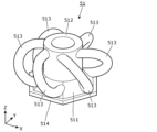
- Fig. 5 is a perspective view of the mirror element 51 according to the embodiment, as viewed from the positive direction of the Z axis.
- Fig. 6 is a perspective view of the mirror element 51 according to the embodiment, as viewed from the negative direction of the Z axis.
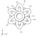
- Fig. 7 is a plan view of the mirror element 51 according to the embodiment, as viewed from the positive direction of the Z axis.
- Fig. 8 is a side view of the mirror element 51 according to the embodiment, as viewed from the negative direction of the Y axis.
- the mirror element 51 has a mirror portion 511, an axis portion 512, and a plurality of connecting portions 513.
- the mirror portion 511 is formed in a substantially hexagonal truncated pyramid shape, and the surface facing the negative Z-axis direction is the reflective surface 514.
- the reflective surface 514 reflects the light emitted by the light-emitting portion 30.
- the reflective surface 514 is formed in a hexagonal shape in a planar view. Note that the reflective surface 514 does not have to be planar, and is not limited to a hexagonal shape in a planar view.
- the shaft portion 512 is disposed in the center of the mirror portion 511 when viewed in the positive Z-axis direction.
- the shaft portion 512 extends in the positive Z-axis direction from the end of the mirror portion 511 in the positive Z-axis direction.
- the shaft portion 512 extends in the normal direction of the reflecting surface 514 (Z-axis direction) from the side opposite the reflecting surface 514 of the mirror portion 511.
- the shaft portion 512 is formed in a cylindrical shape with the end in the positive Z-axis direction open.
- the multiple connecting portions 513 are arranged at equal intervals in the circumferential direction of the shaft portion 512.
- Each connecting portion 513 is a curved rod-shaped portion that protrudes outward from the shaft portion 512 when viewed in the Z-axis direction.
- the axial cross-sectional shape of each connecting portion 513 is approximately circular.
- Each connecting portion 513 also protrudes from the mirror portion 511.
- Each connecting portion 513 is provided for one side of the reflecting surface 514. As described above, in this embodiment, the shape of the reflecting surface 514 in a plan view is hexagonal, so six connecting portions 513 are provided.
- Each connecting portion 513 only protrudes from one side of the reflecting surface 514 and does not interfere with the other sides.
- Each connecting portion 513 has one end connected to the end of the shaft portion 512 in the positive Z-axis direction, and the other end connected to the side of the mirror portion 511.
- one end of the connecting portion 513 is positioned at a position shifted in the clockwise direction from the other end when viewed in the Z-axis direction (see FIG. 7).
- the other end of one connecting portion 513 arranged in the clockwise direction is positioned at approximately the same position as one end of the other connecting portion 513 arranged in the counterclockwise direction when viewed in the Z-axis direction (see FIG. 7).
- each connecting portion 513 is inclined at a predetermined angle ⁇ with respect to the shaft portion 512 when viewed from a direction perpendicular to the normal direction (Z-axis direction) of the reflecting surface 514 (see FIG. 8).
- the direction perpendicular to the normal direction of the reflecting surface 514 is the direction in which the projected area of the target connecting portion 513 is smallest.
- the specified angle ⁇ is preferably in the range of greater than 0 degrees and less than or equal to 45 degrees, and more preferably in the range of greater than or equal to 10 degrees and less than or equal to 35 degrees.
- FIG. 9 is a plan view of the connection between mirror elements 51 according to the embodiment, as viewed from the positive direction of the Z axis.
- FIG. 10 is a side view of the connection between mirror elements 51 according to the embodiment, as viewed from the negative direction of the Y axis.
- the other mirror elements 51 that make up the assembly 54 are connected in the same manner.
- two adjacent mirror elements 51 are arranged so that one side of the reflective surfaces 514 is adjacent to each other.
- the connecting portions 513 corresponding to these one sides are connected to each other.
- one connecting portion 513 is arranged in the space formed by the other connecting portion 513 and penetrates through it.
- This state can also be said to be one connecting portion 513 arranged in the space formed by the other connecting portion 513 and penetrating it. Since the connecting portions 513 inclined with respect to the shaft portion 512 when viewed from a direction perpendicular to the Z-axis direction are connected to each other, it is possible to smoothly deform the assembly 54 while suppressing the gap (non-reflective area) between the reflective surfaces 514.
- the mirror elements 51 are manufactured by a 3D printer. In other words, by manufacturing all of the mirror elements 51 constituting the assembly 54 at once by a 3D printer, it is possible to combine the respective connecting parts 513.
- the mirror elements 51 may be made of resin or metal.
- at least one of polishing the entire assembly and coating it with fluororesin may be performed. Note that these treatments may be performed only on the connecting parts 513. It is possible to make the surface of the mirror part 511 in the negative Z-axis direction the reflective surface 514 as it is after manufacturing by the 3D printer, but the reflective performance of the reflective surface 514 may be improved by performing a mirror finish on the surface or laminating a reflective layer on the surface.
- the support section 52 is a circular plate-shaped frame, and an assembly 54 of multiple mirror elements 51 is arranged inside it.
- the support section 52 supports the assembly 54 via multiple elastic members 53.
- the elastic members 53 pull on the assembly 54, so that the surface of the assembly 54 in the negative Z-axis direction (each reflecting surface 514) becomes flat overall (see Figure 2).
- the deformation section 60 has an axis 61, a guide section 62 that holds the axis 61 so that it can slide freely, and a number of wires 63 that connect the guide section 62 to the support section 52.
- the shaft body 61 is a cylindrical rod extending in the Z-axis direction and is movable in the Z-axis direction.
- the shaft body 61 may be driven manually or by power from a drive source.
- the amount of movement of the shaft body 61 may be adjusted based on the control of a control unit.
- the drive source include a motor and a solenoid.
- the control unit include a microcomputer.
- the guide portion 62 is a cylinder extending in the Z-axis direction.
- the shaft body 61 penetrates the guide portion 62 in the Z-axis direction. This allows the guide portion 62 to guide the sliding movement of the shaft body 61 in the Z-axis direction.
- the shaft body 61 and the guide portion 62 are an example of a sliding mechanism.
- the guide portion 62 is fixed to a predetermined position by a fixing device (not shown).
- the multiple wires 63 are arranged at equal intervals in the circumferential direction when viewed in the Z-axis direction. One end of each wire 63 is connected to the guide portion 62, and the other end is connected to the support portion 52.
- FIG. 11 is a cross-sectional view showing the mirror device 40 after deformation according to the embodiment.
- the assembly 54 after deformation has each reflective surface 514 that is spherical overall.
- the connecting portions 513 of two adjacent mirror elements 51 are connected to each other, so the gap (non-reflective area) between the reflective surfaces 514 can be made as small as possible.
- the diffusion section 70 is a diffusion plate that diffuses the light reflected by the mirror device 40.
- the diffusion section 70 is disposed between the opening 21 of the housing 20 and the mirror device 40. The light reflected by each mirror element 51 is diffused by the diffusion section 70, thereby suppressing the graininess.
- the first light distribution pattern of the light reflected by the mirror device 40 is circular.
- the second light distribution pattern of the light reflected by the mirror device 40 becomes a circle that is larger than the first light distribution pattern.
- each reflecting surface 514 can be deformed into a wider variety of shapes, and accordingly, a wider variety of light distribution patterns can be produced.
- Other shapes include, for example, cylindrical surfaces, conical surfaces, and free-form surfaces.
- the curvature can be adjusted by adjusting the amount of movement of the shaft bodies 61.
- the mirror device 40 in this embodiment comprises a freely deformable reflective section 50 and a deformation section 60 that deforms the reflective section 50.
- the reflective section 50 has a plurality of mirror elements 51 connected to each other.
- the mirror element 51 comprises a mirror section 511 having a reflective surface 514, an axis section 512 extending in the normal direction (Z-axis direction) of the reflective surface 514 from the opposite side of the reflective surface 514 of the mirror section 511, and a connecting section 513 that protrudes outward from the axis section 512 when viewed from the normal direction so as to be inclined at a predetermined angle ⁇ relative to the axis section 512 when viewed from a direction perpendicular to the normal direction, and the connecting section 513 is connected to the connecting section 513 of another mirror element 51.
- the lighting device 10 also includes the mirror device 40 and a light-emitting unit 30 that emits light toward the multiple mirror elements 51 of the mirror device 40.
- two adjacent mirror elements 51 are connected by connecting portions 513 that are inclined relative to the axis portions 512 when viewed from a direction perpendicular to the normal direction of the reflecting surfaces 514, making it possible to smoothly deform the assembly 54 while suppressing gaps (non-reflective regions) between the reflecting surfaces 514. Since the non-reflective regions can be suppressed in this way, a decrease in reflection efficiency can be suppressed.
- the sliding mechanism (shaft 61 and guide 62) of the deformation section 60 slides to deform the reflecting section 50, so the deformation section 60 can be deformed with a relatively simple structure.
- the overall shape of each reflecting surface 514 can be deformed in a variety of ways.
- the elastic member 53 connects the support portion 52 to at least one mirror element 51 of the assembly 54, so that the elastic force of the elastic member can improve the reproducibility of the shape of the assembly 54.
- the deformation section 60 including a slide mechanism is exemplified.
- the deformation section may have any shape as long as it deforms the reflective section.
- FIG. 12 is a plan view showing the reflective section 50a and the deformation section 60a according to the first modification.
- FIG. 13 is a perspective view showing the reflective section 50a according to the first modification.
- the connecting parts 55a are attached to the mirror elements 51a that form each corner of the assembly 54a.
- the connecting parts 55a are disposed on the shaft parts 512a of each mirror element 51a, and are hooks that protrude from the shaft parts 512a in the positive direction of the Z axis.
- the deformation portion 60 has one wire 65a.
- This wire 65a is inserted through each connection portion 55a.
- the wire 65a is hexagonal in shape, and both ends are pulled outward from one connection portion 55a. By pulling out both ends of the wire 65a further, the assembly 54a is closed in a purse-like shape, and each reflection surface 514 becomes spherical.
- wire 65a is connected between at least two mirror elements 51a in this manner, it is possible to smoothly deform the assembly 54a by moving the wire 65a.
- the mirror element 51a is provided with a connection portion 55a to which the wire 65a is connected, so the wire 65a can be smoothly attached to the mirror element 51a via the connection portion 55a.
- FIG. 14 is a plan view showing the reflecting portion 50a and the deforming portion 60b according to the second modification.
- the deforming portion 60b has a plurality of wires 65b.
- Each wire 65b is bridged between the connecting portions 55a arranged at a pair of diagonal corners of the assembly 54a.
- the assembly 54a is closed in a purse-like shape, and each reflecting surface 514 becomes spherical.
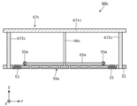
- FIGS. 15 and 16 are side views showing the deformation portion 60c according to the third modified example. As shown in FIGS. 15 and 16, the deformation portion 60c has a fixing portion 66c and a guide portion 67c in addition to the wire 65a.
- the fixing portion 66c is a portion that fixes the position of a portion of the reflecting portion 50a. Specifically, the fixing portion 66c is disposed in the positive direction of the Z axis from the center of the assembly 54a in order to fix the position of the center of the assembly 54a when viewed in the Z axis direction.
- the fixing portion 66c is a support that extends in the Z axis direction, with one end of the support being in contact with the center of the assembly 54a and the other end being fixed to the guide portion 67c.
- the guide section 67c has a base 671c to which the other end of the fixed section 66c is fixed, and multiple guide shafts 672c protruding from the base 671c.
- the base 671c is a flat plate parallel to the XY plane, and each guide shaft 672c protrudes from its end in the negative Z direction.
- Each guide shaft 672c is an axle that extends in the Z direction, and slidably passes through the support section 52a of the reflector 50a.
- the support portion 52a moves in the positive direction of the Z axis while the fixing portion 66c holds down the center of the assembly 54a.
- This movement of the support portion 52a is guided by each guide shaft 672c of the guide portion 67c, allowing for stable movement.
- the peripheral portion of the assembly 54a also moves in the positive direction of the Z axis, resulting in smooth deformation of the assembly 54a.
- the support portion 52a and the assembly 54a are connected by the elastic member 53, so the posture of the assembly 54a is also stable.
- the guide portion 67c guides the movement of the support portion 52a while the fixing portion 66c holds down the center of the assembly 54a, so that the assembly 54a can be deformed stably.
- FIG 17 is a perspective view showing a reflecting section 50d according to variant example 4.
- the reflecting section 50d is provided with a frame material 59d that supports the assembly 54.
- the frame material 59d is attached to the assembly 54 by being placed on the surface of the assembly 54 in the positive Z-axis direction, i.e., the side opposite the mirror sections 511.
- the frame material 59d is a leaf spring, and has multiple beams 591d extending from the center of the assembly 54 so as to connect each corner of the assembly 54.
- the assembly 54 can be evenly deformed via the frame material 59d.
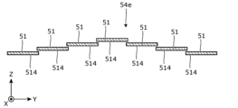
- FIG. 18 is a cross-sectional view showing an assembly 54e relating to variant example 5. As shown in FIG. 18, in assembly 54e, two adjacent mirror elements 51 overlap each other when viewed in the Z-axis direction.
- the planar shape of the reflecting surface 514 of each mirror element 51 is hexagonal.
- the planar shape of the reflecting surface may be another polygon, or may be a circle, an ellipse, an oval, or the like. This also applies to the assembly.
- the diffusing section 70 is a diffusing plate arranged in a position facing the mirror device 40.
- the diffusing section may be arranged in any location as long as it can diffuse the light reflected by the reflecting section.
- the diffusing section may be laminated on the reflecting surface of each mirror element.
- the light source 32 is a laser element or an LED.
- other light sources may be used. Examples of other light sources include incandescent light bulbs, halogen light bulbs, and fluorescent lights.
- each reflecting surface 514 of the assembly 54 is deformed from a flat surface to a convex curved surface as a whole is illustrated.
- the present invention also includes forms obtained by applying various modifications to the embodiments that a person skilled in the art may conceive, and forms realized by arbitrarily combining the components and functions of each embodiment within the scope of the spirit of the present invention.
- the lighting device according to the present invention is not limited to the following examples.
- the mirror device of Technology 1 includes a freely deformable reflecting section and a deforming section that deforms the reflecting section, the reflecting section includes a plurality of mirror elements connected to each other, and the mirror elements include a mirror section having a reflecting surface, an axis section that extends in a normal direction to the reflecting surface from the opposite side of the reflecting surface of the mirror section, and a connecting section that protrudes outward from the axis section when viewed from the normal direction so as to be inclined at a predetermined angle to the axis section when viewed from a direction perpendicular to the normal direction, and that is connected to a connecting section of another mirror element.
- Technology 2 is a mirror device according to Technology 1, in which the deformation section includes a sliding mechanism that deforms the reflection section by sliding.
- Technology 3 is a mirror device according to Technology 1 or Technology 2, in which the deformation section includes a wire connecting at least two of the multiple mirror elements.
- Technology 4 is a mirror device according to Technology 3, in which the mirror element is disposed on the shaft portion and has a connection portion to which the wire is connected.
- Technology 5 is a mirror device according to any one of Technology 1 to Technology 4, which includes a support section that supports the reflecting section, and an elastic member that connects at least one of the multiple mirror elements to the support section.
- Technology 6 provides the mirror device described in Technology 5 with a fixing section that fixes the position of a portion of the reflecting section relative to the support section, and a guide section that guides the movement of the support section.
- Technology 7 is a mirror device according to any one of Technology 1 to Technology 6, in which the mirror portions of two adjacent mirror elements among the plurality of mirror elements overlap when viewed from the normal direction.
- Technology 8 is a mirror device according to any one of Technology 1 to Technology 7, which has a frame material that supports the multiple mirror elements by stacking them from the side opposite the mirror portion.
- the lighting device of Technology 9 includes a mirror device according to any one of Technology 1 to Technology 8, and a light-emitting unit that emits light toward the multiple mirror elements of the mirror device.
- Reference Signs List 10 Illumination device 30 Light-emitting section 40
- Shaft body 62 Guide section 63 Wire material 65a, 65b Wire 66c Fixation section 67c Guide section 511 Mirror section 512, 512a Shaft section 513 Connection section 514 Reflection surface 672c Guide axis ⁇ Predetermined angle
Landscapes
- Physics & Mathematics (AREA)
- General Physics & Mathematics (AREA)
- Optics & Photonics (AREA)
- Engineering & Computer Science (AREA)
- General Engineering & Computer Science (AREA)
- Non-Portable Lighting Devices Or Systems Thereof (AREA)
Abstract
L'invention concerne un dispositif miroir (40) comprenant une partie de réflexion déformable (50) et une partie de déformation (60) pour déformer la partie de réflexion. La partie de réflexion comporte une pluralité d'éléments miroirs (51) reliés les uns aux autres. Les éléments miroirs comprennent chacun : une partie miroir (511) ayant une surface de réflexion (514) ; une partie arbre (512) s'étendant dans la direction normale de la surface de réflexion (direction de l'axe Z) depuis le côté opposé à la surface de réflexion de la partie miroir ; et une partie de connexion (513) qui fait saillie vers l'extérieur de la partie arbre lorsqu'elle est vue depuis la direction normale de façon à être inclinée selon un angle prescrit (α) par rapport à la partie arbre lorsqu'elle est vue depuis une direction orthogonale à la direction normale, et qui est connectée à une partie de connexion d'un autre des éléments miroirs.
Priority Applications (1)
| Application Number | Priority Date | Filing Date | Title |
|---|---|---|---|
| JP2025527540A JPWO2024257505A1 (fr) | 2023-06-13 | 2024-05-08 |
Applications Claiming Priority (2)
| Application Number | Priority Date | Filing Date | Title |
|---|---|---|---|
| JP2023-097276 | 2023-06-13 | ||
| JP2023097276 | 2023-06-13 |
Publications (1)
| Publication Number | Publication Date |
|---|---|
| WO2024257505A1 true WO2024257505A1 (fr) | 2024-12-19 |
Family
ID=93851971
Family Applications (1)
| Application Number | Title | Priority Date | Filing Date |
|---|---|---|---|
| PCT/JP2024/017037 Ceased WO2024257505A1 (fr) | 2023-06-13 | 2024-05-08 | Dispositif miroir et dispositif d'éclairage |
Country Status (2)
| Country | Link |
|---|---|
| JP (1) | JPWO2024257505A1 (fr) |
| WO (1) | WO2024257505A1 (fr) |
Citations (8)
| Publication number | Priority date | Publication date | Assignee | Title |
|---|---|---|---|---|
| JPS5635102A (en) * | 1979-08-03 | 1981-04-07 | Shikopa Sa Soc Intern Dou Cons | Pivotable parabolic reflector and producing same |
| WO2006006240A1 (fr) * | 2004-07-14 | 2006-01-19 | Mitsubishi Denki Kabushiki Kaisha | Dispositif réflecteur |
| JP2009139761A (ja) * | 2007-12-07 | 2009-06-25 | Mitaka Koki Co Ltd | 太陽追尾集光装置 |
| JP2009151211A (ja) * | 2007-12-21 | 2009-07-09 | Mitsui Eng & Shipbuild Co Ltd | 取付姿勢測定装置 |
| JP2010160033A (ja) * | 2009-01-07 | 2010-07-22 | Denso Corp | ファブリペロー干渉計及びその製造方法 |
| JP2014160211A (ja) * | 2013-02-20 | 2014-09-04 | Canon Inc | ミラーユニットおよび画像取得装置 |
| JP2014203905A (ja) * | 2013-04-03 | 2014-10-27 | 株式会社ニコン | 照明方法及び装置、並びに露光方法及び装置 |
| JP2019003216A (ja) * | 2013-12-09 | 2019-01-10 | 株式会社ブイ・テクノロジー | 露光装置、露光方法 |
-
2024
- 2024-05-08 WO PCT/JP2024/017037 patent/WO2024257505A1/fr not_active Ceased
- 2024-05-08 JP JP2025527540A patent/JPWO2024257505A1/ja active Pending
Patent Citations (8)
| Publication number | Priority date | Publication date | Assignee | Title |
|---|---|---|---|---|
| JPS5635102A (en) * | 1979-08-03 | 1981-04-07 | Shikopa Sa Soc Intern Dou Cons | Pivotable parabolic reflector and producing same |
| WO2006006240A1 (fr) * | 2004-07-14 | 2006-01-19 | Mitsubishi Denki Kabushiki Kaisha | Dispositif réflecteur |
| JP2009139761A (ja) * | 2007-12-07 | 2009-06-25 | Mitaka Koki Co Ltd | 太陽追尾集光装置 |
| JP2009151211A (ja) * | 2007-12-21 | 2009-07-09 | Mitsui Eng & Shipbuild Co Ltd | 取付姿勢測定装置 |
| JP2010160033A (ja) * | 2009-01-07 | 2010-07-22 | Denso Corp | ファブリペロー干渉計及びその製造方法 |
| JP2014160211A (ja) * | 2013-02-20 | 2014-09-04 | Canon Inc | ミラーユニットおよび画像取得装置 |
| JP2014203905A (ja) * | 2013-04-03 | 2014-10-27 | 株式会社ニコン | 照明方法及び装置、並びに露光方法及び装置 |
| JP2019003216A (ja) * | 2013-12-09 | 2019-01-10 | 株式会社ブイ・テクノロジー | 露光装置、露光方法 |
Also Published As
| Publication number | Publication date |
|---|---|
| JPWO2024257505A1 (fr) | 2024-12-19 |
Similar Documents
| Publication | Publication Date | Title |
|---|---|---|
| JP5711147B2 (ja) | Led、光ガイド及びリフレクタを備える光源 | |
| US9366410B2 (en) | Reverse total internal reflection features in linear profile for lighting applications | |
| JP6271216B2 (ja) | 発光ユニットおよび照明装置 | |
| JP2010500710A (ja) | 光源及び光ガイドを有すること照明装置 | |
| US11104265B2 (en) | Lighting device for a motor vehicle headlight | |
| JP6890287B2 (ja) | 照明器具 | |
| JP6473966B2 (ja) | 照明装置および移動体 | |
| CN108291702B (zh) | 光源装置、照明装置和车辆用灯具 | |
| WO2009040725A2 (fr) | Lampe à laser | |
| WO2024257505A1 (fr) | Dispositif miroir et dispositif d'éclairage | |
| JP7304520B2 (ja) | 照明装置 | |
| JP2008053660A (ja) | 発光モジュール | |
| KR20120137719A (ko) | 등기구 | |
| JP2018037257A (ja) | 面光源装置および液晶表示装置 | |
| JP5419852B2 (ja) | 照明装置 | |
| JP6041082B2 (ja) | 照明装置 | |
| WO2024252849A1 (fr) | Dispositif d'éclairage | |
| WO2016175214A1 (fr) | Dispositif d'éclairage et élément optique | |
| JP6443751B2 (ja) | 照明装置、照明システム及び移動体 | |
| JP7515107B2 (ja) | 照明器具 | |
| JP2014203604A (ja) | 照明装置 | |
| CN107940268B (zh) | 激光模组及激光照明灯 | |
| JP2012199055A (ja) | 発光装置 | |
| JP2022099124A (ja) | 光学レンズ及び照明装置 | |
| JP7046305B2 (ja) | 光学装置および照明装置 |
Legal Events
| Date | Code | Title | Description |
|---|---|---|---|
| 121 | Ep: the epo has been informed by wipo that ep was designated in this application |
Ref document number: 24823127 Country of ref document: EP Kind code of ref document: A1 |
|
| ENP | Entry into the national phase |
Ref document number: 2025527540 Country of ref document: JP Kind code of ref document: A |
|
| WWE | Wipo information: entry into national phase |
Ref document number: 2025527540 Country of ref document: JP |
|
| NENP | Non-entry into the national phase |
Ref country code: DE |