WO2024257559A1 - Optical system and head-up display device - Google Patents
Optical system and head-up display device Download PDFInfo
- Publication number
- WO2024257559A1 WO2024257559A1 PCT/JP2024/018554 JP2024018554W WO2024257559A1 WO 2024257559 A1 WO2024257559 A1 WO 2024257559A1 JP 2024018554 W JP2024018554 W JP 2024018554W WO 2024257559 A1 WO2024257559 A1 WO 2024257559A1
- Authority
- WO
- WIPO (PCT)
- Prior art keywords
- light
- surface side
- microlens
- optical system
- display device
- Prior art date
- Legal status (The legal status is an assumption and is not a legal conclusion. Google has not performed a legal analysis and makes no representation as to the accuracy of the status listed.)
- Ceased
Links
Images








Classifications
-
- B—PERFORMING OPERATIONS; TRANSPORTING
- B60—VEHICLES IN GENERAL
- B60K—ARRANGEMENT OR MOUNTING OF PROPULSION UNITS OR OF TRANSMISSIONS IN VEHICLES; ARRANGEMENT OR MOUNTING OF PLURAL DIVERSE PRIME-MOVERS IN VEHICLES; AUXILIARY DRIVES FOR VEHICLES; INSTRUMENTATION OR DASHBOARDS FOR VEHICLES; ARRANGEMENTS IN CONNECTION WITH COOLING, AIR INTAKE, GAS EXHAUST OR FUEL SUPPLY OF PROPULSION UNITS IN VEHICLES
- B60K35/00—Instruments specially adapted for vehicles; Arrangement of instruments in or on vehicles
- B60K35/20—Output arrangements, i.e. from vehicle to user, associated with vehicle functions or specially adapted therefor
- B60K35/21—Output arrangements, i.e. from vehicle to user, associated with vehicle functions or specially adapted therefor using visual output, e.g. blinking lights or matrix displays
- B60K35/23—Head-up displays [HUD]
-
- G—PHYSICS
- G02—OPTICS
- G02B—OPTICAL ELEMENTS, SYSTEMS OR APPARATUS
- G02B27/00—Optical systems or apparatus not provided for by any of the groups G02B1/00 - G02B26/00, G02B30/00
- G02B27/01—Head-up displays
Definitions
- the present invention relates to an optical system and a head-up display device.
- Head-up display devices are known that project an image onto the windshield of a moving object such as an automobile or aircraft, allowing the projected image to be viewed as a virtual image through the windshield.
- Patent Document 1 discloses a conventional head-up display device that "includes a projection optical system that projects light from behind a transmissive liquid crystal display panel and enlarges and projects the image displayed on the liquid crystal display panel.”
- the driver observes a virtual image by projecting an "enlarged real image of the image formed by the relay lens" onto the windshield using a projection lens.
- a projection lens By obtaining an enlarged real image of the liquid crystal display panel using the relay lens, it is possible to use a small liquid crystal display panel.
- FIGS. 7A, 7B, and 7C are explanatory diagrams showing the relationship between the miniaturization of the image display element 2 and the projection optical system 20b.
- the projection optical system 20b includes at least the mirror 5 and the windshield 6.
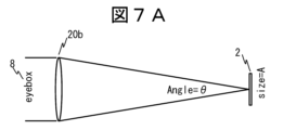
- FIG. 7A is a diagram showing an image display element 2 of a reference size.
- the size of the reference image display element 2 is designated as A.
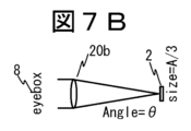
- FIG. 7B is a diagram showing an example of a small image display element 2.
- FIG. 7B is a diagram of FIG. 7A miniaturized by being transformed to 1/3 the size, with the size of the image display element 2 being A/3. With the configuration of FIG. 7B, the size of the eye box 8 is also small, so it is not possible to ensure the size of the eye box 8 required for the head-up display device 30.
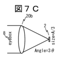
- FIG. 7C is a diagram showing another example of a small image display element 2.
- Fig. 7C like Fig. 7B, the size of the image display element 2 is A/3, but the size of the eye box 8 is returned to the same size as in Fig. 7A.
- the LCD panel is made smaller, the optical performance of the projection optical system will be significantly degraded, or a larger number of lenses will be required to ensure the optical performance, resulting in a problem of larger size. Furthermore, if only the image display element 2 is made smaller, the virtual image will also become smaller, narrowing the viewing angle of the head-up display device.
- the present invention was made in consideration of the above-mentioned circumstances, and aims to provide a small head-up display device.
- one representative head-up display device of the present invention includes a display panel, a light source that supplies light to the display panel, a relay optical system that maps the image light emitted from the display panel, and a diffusion element that diffuses the image light mapped by the relay optical system, and the diffusion element has different optical effects in the horizontal and vertical directions of the diffusion element that correspond to the horizontal and vertical directions of the viewer.
- the present invention provides a small head-up display device. Problems, configurations, and advantages other than those described above will become clear from the description of the following embodiment.
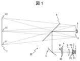
- FIG. 1 is a schematic configuration diagram of a head-up display device.
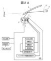
- 1 is a schematic configuration and functional block diagram of a head-up display device.
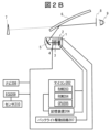
- 1 is a schematic configuration and functional block diagram of a head-up display device.
- FIG. 1 is a plan view of a vehicle, which is a moving object equipped with a head-up display device, as viewed from the front.
- FIG. 13 is a diagram showing a configuration using a display panel of a standard size.
- FIG. 1 is a diagram showing a configuration using a display panel, a relay optical system, and a screen plate.
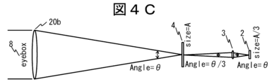
- FIG. 13 is a diagram showing a configuration using a display panel, a relay optical system, and a diffusion element unit.
- FIG. 1 is a schematic configuration diagram of a head-up display device.
- 1 is a schematic configuration and functional block diagram of a head-up display device.
- FIG. 1 is a plan view of a vehicle, which is a moving object equipped with a head-up
- FIG. 4 is a diagram showing an example of a configuration of a diffusion element portion.
- 13 is a diagram showing another example of the configuration of the diffusion element portion.
- FIG. 13 is a diagram showing another example of the configuration of the diffusion element portion.
- FIG. 13 is a diagram showing the diffusion of image light when no microlenses are used.
- FIG. 13 is a diagram showing an example of diffusion of image light when a microlens is used.
- 13A and 13B are diagrams illustrating another example of diffusion of image light when a microlens is used.
- 13A and 13B are diagrams illustrating another example of diffusion of image light when a microlens is used.
- 1A to 1C are diagrams illustrating an example of a projection optical system depending on the size of a display panel.
- FIG. 1A to 1C are diagrams illustrating an example of a projection optical system depending on the size of a display panel.
- 1A to 1C are diagrams illustrating an example of a projection optical system depending on the size of a display panel.
- FIG. 1 is a schematic configuration diagram of a head-up display device.
- 1 is a schematic configuration and functional block diagram of a head-up display device.
- 1 is a schematic configuration and functional block diagram of a head-up display device.
- 3A and 3B are diagrams illustrating the basic configuration and function of a diffusion element portion.
- FIG. 13 is a diagram showing mapping of incident light rays on a diffusion element portion.
- FIG. 13 is a diagram showing mapping of emitted light rays from a diffusion element portion.
- FIG. 11 is a diagram showing an example of lens data of a diffusion element portion.
- FIG. 13 is a diagram showing an example of free-form surface coefficients of a diffusion element portion.
- FIG. 13 is a diagram showing an example of diffusion of image light when a microlens is used.
- FIG. 13 is a diagram showing an example of diffusion of image light, with the same incident light as that shown in FIG. 1A and 1B are diagrams showing examples of ray diagrams in the YZ section and the XZ section of a free curved lens;
- FIG. 13 is a diagram showing another example of lens data of the diffusion element portion.
- FIG. 11 is a diagram showing another example of the free-form surface coefficients of the diffusion element portion.
- FIG. 13A and 13B are diagrams illustrating another example of diffusion of image light when a microlens is used.
- 13 is a diagram showing another example of diffusion of image light, with the same incident light as that of the image light without a microlens.
- FIG. 11A and 11B are diagrams showing another example of ray diagrams in the YZ section and the XZ section of the free curved lens.
- the basic configuration of the head-up display device 30 will be described using FIG. 1.
- the head-up display device may also be called a display device, a virtual image display device, etc.
- the head-up display device 30 shown in FIG. 1 includes an image forming unit and an image projection unit.
- the image forming unit includes a light source 1 and an image display element or display panel 2.
- the image projection unit may include a mirror 5.
- the light source 1 emits light to the image display element or display panel 2, and then the image light from the display panel 2 is incident on the mirror 5, and the image light emitted from the mirror 5 is reflected by the windshield 6 of a vehicle (for example, the automobile 500 in FIG. 3) and incident on the observer's eye 9.
- the projection of the image light onto the windshield 6 of the vehicle is described, but the projection unit that projects the image light may be a projection member such as a combiner.
- the projection unit that projects the image light may be a projection member such as a combiner.
- the mirror 5 functions as an image projection unit that magnifies and reflects the image light from the image display element or display panel 2 in a direction at a set angle or in a specified direction.
- the mirror 5 is, for example, a concave mirror (magnifying mirror) and is provided on the optical path between the image display element or display panel 2 and the windshield 6.
- the mirror 5 functions as an image light projection unit that projects the image light emitted from the display panel 2 onto the windshield 6, thereby causing the projected image light to be visually recognized as a virtual image by the eye 9 of a user such as a driver.
- the mirror 5 in this embodiment is composed of a mirror having a concave reflective surface.
- the head-up display device includes a display panel 2, a light source 1, and a controller 200 that controls the operations of these components.
- the head-up display device further includes a relay optical system 3 and a diffusion element unit 4. Light is irradiated from the light source 1 to the display panel 2, and image information (video information) displayed on the display panel 2 is emitted toward the mirror 5 via the relay optical system 3 and the diffusion element unit 4.
- the combination of the light source 1, the display panel 2, the relay optical system 3, and the diffusion element unit 4 may be referred to as an optical system.
- the light source 1 is typically configured to include an LED (Light Emitting Diode) light source, and multiple light sources may be arranged for use.
- the image display element or display panel 2 is typically a liquid crystal panel (Liquid Crystal Display: LCD).
- the display panel 2 creates an image based on image data input instructed by the controller 200, and displays it on the display surface of the display element of the display panel 2.
- the image display element 2 may be referred to as a liquid crystal display panel, liquid crystal display element, display element, display panel, etc.
- the light source 1 may also be referred to as a backlight.
- the head-up display device 30 is a device equipped with a controller 200. Also, as shown in FIG. 2B, if the controller 200 is not provided, it is possible for the control unit of the automobile to function as the controller 200. When controlled by the control unit of the automobile, the control is almost the same as that of the controller 200 of the head-up display device 30, and the following embodiment will be described using the controller 200 of the head-up display device 30. In other words, the head-up display device 30 may be equipped with the controller 200, or an external control device such as an automobile may be used.
- a navigation system 208 which is a navigation device that generates and outputs information related to the operation of the mobile object equipped with the head-up display device 30, and an ECU (Electronic Control Unit) 209 that controls the operation of the mobile object are connected to the controller 200.
- Various sensors 210 equipped on the mobile object are connected to the ECU 209, and the ECU 209 is configured to notify the ECU 209 of the detected information.
- the controller 200 includes a microcomputer 202 that processes various data from the external devices described above, a storage device 206 connected to the microcomputer 202, and a backlight drive circuit 207 for driving the backlight 1.
- the microcomputer 202 is equipped with a RAM (Random Access Memory) 203 for storing various data from external devices, a CPU (Central Processing Unit) 205 for performing calculations to generate image data that is the basis of the virtual image viewed by the observer, and a ROM (Read Only Memory) 204 for storing programs and parameters that can execute the calculations in the CPU 205.
- a RAM Random Access Memory
- CPU Central Processing Unit
- ROM Read Only Memory
- the controller 200 having the above configuration displays image information on the image display element 2.
- the image information displayed on the image display element 2 is emitted as image light by the light emitted by the backlight 1 through the relay optical system 3 and the diffusion element section 4 towards the mirror 5.
- the image light emitted from the display panel 2 is projected onto the windshield 6 by the mirror 5.
- the image light projected from the mirror 5 onto the windshield 6 is reflected by the windshield 6 and reaches the position of the observer's eye 9. This creates a relationship as if the observer's eye 9 were looking at the image information on the virtual image surface 7. Note that if the mirror 5 is not provided, the image light from the display panel 2 is emitted onto the windshield 6, and the image light emitted onto the windshield 6 is reflected by the windshield 6 and reaches the position of the observer's eye 9.
- the eyebox 8 is the range in which points V1, V2, and V3 on the virtual image plane 7 can be seen even if the observer moves the position of the eye 9.
- the relay optical system 3, the diffusion element section 4, and the mirror 5 may be called a projection optical system that displays an image (virtual image) of an object (spatial image) in front of the observer's eye 9. Note that the projection optical system does not have to include the mirror 5.
- FIG. 3 is a plan view of an automobile 500, which is a moving body equipped with a head-up display device 30, as seen from the front.
- a windshield 6 which is a front glass used as a windshield, is disposed in front of the driver's seat.
- the head-up display device 30 projects image light onto the windshield 6, allowing the driver and observers in the vehicle 500 to view various information related to the vehicle 500 as virtual images.
- the image light is projected onto the front of the driver's seat or its surroundings. For example, the image light is projected onto the position shown in the dashed rectangular area R1.
- the projection optical system 20b includes a mirror 5 ( Figure 2A).
- the mirror 5 is a concave mirror, and has a light-collecting effect, so it has the same effect as a convex lens.
- the projection optical system 20b is not a convex lens, and the optical components may include a concave lens in addition to the mirror 5.
- Fig. 4A is a diagram showing a configuration using an image display element 2 of a standard size.
- the size of the standard image display element 2 is designated as A.
- Fig. 4B is a diagram showing a configuration using a small image display element 2, relay optical system 3, and screen plate 4b.
- the size of the image display element 2 is A/3.
- a relay optical system 3 with a magnification of 3x is used to map onto the screen plate 4b, ensuring the size of the eyebox 8.
- the angle of the relay optical system 3 on the screen plate 4b side is ⁇
- the angle of the relay optical system 3 on the image display element 2 side is 3 ⁇
- Fig. 4C is a diagram showing a configuration using a small image display element 2, relay optical system 3, and diffusion element section 4.
- the size of the image display element 2 is A/3, but the angle of the relay optical system 3 on the image display element 2 side remains ⁇ , and the angle of the relay optical system 3 on the diffusion element section 4 side is set to ⁇ /3, and the diffusion element section 4 diffuses the image light, ensuring the size of the eye box 8.
- the angle ⁇ in Fig. 4C is made up of the light entering the upper part of the relay optical system 3 from the image display element 2 and the light entering the lower part of the relay optical system 3.
- Fig. 4C makes it possible to use a small image display element 2 without enlarging the relay optical system 3. Details of this diffusion element section 4 will be described with reference to Figs. 5A to 5C.
- the X-axis is the horizontal direction, left-right direction, lateral direction or width direction of the vehicle
- the Y-axis is the up-down direction, vertical direction or length direction of the vehicle
- the Z-axis which is perpendicular to the lateral direction of the vehicle, is the front-rear direction of the vehicle or the traveling direction of the vehicle.
- the X-axis and Y-axis correspond to the horizontal and vertical directions of the field of view (eye box 8) that the observer can observe.
- the observation range is larger by the distance between the left and right eyes.
- the eye box 8 is 130 mm horizontally and 50 mm vertically. Therefore, the side of the diffusion element 4 that corresponds to the X-axis direction requires a larger observation range than the side that corresponds to the Y-axis direction.
- the radius of curvature of the cylinder lens can only be seen from a specific direction, for example, when the light incident side of the microlens array 41 is viewed from the left or right, and the light exit side of the microlens array 41 is viewed from above or below.
- the light incident side of the microlens array 41 is flat, and the light exit side of the microlens array 41 diffuses light in the vertical and horizontal directions.
- the light incident side of the microlens array 41 diffuses light in the Y-axis direction (vertical direction), and the light exit side of the microlens array 41 diffuses light in the X-axis direction (horizontal direction).
- the light incident side of the microlens array 41 is flat, and the light exit side of the microlens array 41 diffuses light in the horizontal direction.
- the diffusion element section 4 includes a microlens array 41 and a light-shielding grating 42a.
- the light-shielding grating and the microlens array are arranged via an adhesive or a holding section.
- the microlens array 41 has one or more microlenses.
- the light-shielding grating 42a has one or more openings and is arranged on the light-emitting side of the microlens array 41.
- the microlens array 41 also corresponds to the openings of the light-shielding grating 42a.
- One microlens may correspond to one opening, or one or more microlenses may correspond to one opening, and there is no particular limitation.
- the light-shielding grating has an opening, the opening has one or more openings, and the opening corresponds to at least one microlens.
- the openings of the light-shielding grating for performing the shielding action are arranged according to the microlens array.
- Each pixel of the image display element 2 corresponds to each cell of the microlens array 41 mapped by the relay optical system 3.
- the light incident side of the microlens array 41 is flat, and the light exit side of the microlens array 41 diffuses light in both the vertical and horizontal directions.
- the microlens array 41 has different radii of curvature in the XZ cross section and the YZ cross section, and the diffusion angle in the X-axis direction is greater than the diffusion angle in the Y-axis direction.
- the divergence effect of each microlens of the microlens array 41 in the horizontal direction (X-axis direction) is greater than the divergence effect of each microlens of the microlens array 41 in the vertical direction (Y-axis direction).
- the "diffusion effect" in this invention may also be referred to as a "divergence effect”.
- a toroidal lens or a free-form lens can be used as the microlens.
- Each opening of the light-shielding grid 42a corresponds to each lens of the microlens array 41, and blocks light that spreads to the periphery of each cell in the focused image (spot) of light in each cell of the microlens array 41 mapped by the relay optical system 3.
- the aperture ratio of each pixel of the image display element 2 is about 50%, so degradation of resolution is prevented by blocking the light beam of the relay optical system 3 that spreads beyond the magnification.
- Fig. 5B(1) to Fig. 5B(4) are diagrams showing another example of the configuration of the diffusion element section 4.
- the light-shielding grating 42a is arranged on the light-emitting side of the microlens array 41, but in Fig. 5B, the light-shielding grating 42c is arranged on the light-incident side of the microlens array 41, and the light-shielding grating 42b is arranged on the light-emitting side of the microlens array 41.
- the light-shielding grating and the microlens array are arranged by bonding or via a structure, etc.
- the microlenses on the light incident side diffuse light in the Y-axis direction
- the microlenses on the light exit side diffuse light in the X-axis direction
- a light-shielding grating 42b is arranged in the X-axis direction
- a light-shielding grating 42c is arranged in the Y-axis direction.
- the light incident side of the microlens array 41 diffuses light in the vertical direction
- the light exit side of the microlens array 41 diffuses light in the horizontal direction.
- FIG. 5B shows a light-shielding grating arranged in the direction of diffusion
- the light-shielding grating 42a of FIG. 5A may also be used.
- FIGS. 5C(1) to 5C(3) are diagrams showing another example of the configuration of the diffusion element section 4.
- the microlens array 41 in FIG. 5C has a shape with a radius of curvature only in the X-axis direction, and for example, a cylindrical lens array or a free-form lens array can be used.
- the incident side of the microlens array 41 is flat, and the exit side of the microlens array 41 diffuses light in the horizontal direction.
- the microlens array 41 in FIG. 5C has a diffusing effect only in the X-axis direction.
- each microlens of the microlens array 41 has a diverging effect only in the horizontal direction (X-axis). Therefore, in FIG. 5C, a light-shielding grating 42b that has a shading effect only in the Y-axis direction is arranged on the light exit side.
- the light-shielding grating 42b in Fig. 5C may have a shape that has a shielding effect only in the Y-axis direction, or the light-shielding grating 42a in Fig. 5A may be used.
- the microlens array 41 shown in Figs. 5A to 5C may be configured to have different divergence effects on the light incident side and the light exit side.
- the diffusion element unit 4 may have a structure (holding) the microlens array 41 and the light-shielding gratings 42a, 42b, and 42c as an integral unit.
- Each microlens of the microlens array 41 may have a diffusion effect on at least one of the light entrance surface side and the light exit surface side of the diffusion element unit.
- a telecentric optical design may be performed, or a lenticular lens may be disposed immediately before the diffusion element unit 4.
- Figures 6A to 6D show the state in which the image light is incident on the microlens array 41 from the relay optical system 3 side.
- FIG. 6A is a diagram showing the diffusion of image light when no microlenses are used.
- FIG. 6A shows the case where the microlens array 41 is not used as a reference, and the shape of the image light on the image display element side or relay optical system side is approximately the same as that on the Eyebox side.
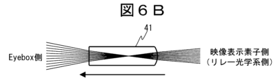
- FIG. 6B is a diagram showing an example of the diffusion of image light when a microlens is used.
- a microlens array 41 with positive refractive power is placed in front of the focusing position of the relay optical system 3, thereby increasing the angle at which the image light is diffused.
- FIG. 6C is a diagram showing another example of diffusion of image light when microlenses are used.
- a microlens array 41 with positive refractive power is placed in front of the focusing position of the relay optical system 3 and with negative refractive power is placed behind the focusing position, thereby further increasing the angle at which the image light is diffused.
- FIG. 6D is a diagram showing another example of diffusion of image light when microlenses are used.
- a microlens array 41 with a decentered negative refractive power is placed after the focusing position of the relay optical system 3, thereby increasing the angle at which the image light is diffused and emitting the light at an angle.
- each microlens of the microlens array 41 may be a decentered lens.
- the head-up display device of this embodiment includes a light source 1, a display panel 2, a relay optical system 3 that maps the image light emitted from the display panel 2, and a diffusion element unit 4 that diffuses the image light mapped by the relay optical system 3.
- a mirror 5 that reflects the image light diffused by the diffusion element unit 4 may also be included. When the mirror 5 is included, the light reflected by the mirror 5 is projected onto a projection member such as a windshield 6 to display a virtual image. When the mirror 5 is not included, the image light diffused by the diffusion element unit 4 is output to a projection member such as a windshield 6 to display a virtual image.
- the diffusion element unit 4 includes a microlens array 41 having a plurality of microlenses, and the microlens array 41 has different optical effects in the horizontal and vertical directions of the microlens array 41, which correspond to the horizontal and vertical directions of the field of view in which the virtual image can be observed.
- the optical performance of the projection optical system 20b can be ensured without increasing the number of lenses, making it possible to provide a compact head-up display device.
- the image display element 2 may be a reflective image display element in addition to a transmissive liquid crystal display panel.
- a telecentric optical design may be used, or a lenticular lens may be placed immediately before the diffusion element section 4.
- the head-up display device 30 may be called a display device, a virtual image display device, or the like.
- the head-up display device 30 shown in FIG. 8 includes an image forming unit and an image projection unit.
- the image forming unit includes a light source 1 and an image display element or display panel 2.
- the image projection unit may include a concave lens 10 and a mirror 5.
- the light source 1 emits light to the image display element or display panel 2, and then the image light from the display panel 2 is incident on the mirror 5, and the image light emitted from the mirror 5 is reflected by the windshield 6 of a vehicle (for example, the automobile 500 in FIG. 3) and incident on the observer's eye 9.
- the projection of the image light onto the windshield 6 of the vehicle is described, but the projection unit that projects the image light may be a projection member such as a combiner.
- the projection unit that projects the image light may be a projection member such as a combiner.
- the mirror 5 functions as an image projection unit that magnifies and reflects the image light from the image display element or display panel 2 in a set angle direction or a specified direction.
- the mirror 5 is, for example, a concave mirror (magnifying mirror) and is provided on the optical path between the image display element or display panel 2 and the windshield 6.
- the mirror 5 functions as an image light projection unit that projects the image light emitted from the display panel 2 onto the windshield 6, thereby causing the projected image light to be visually recognized as a virtual image by the eye 9 of a user such as a driver.
- the mirror 5 in this embodiment is composed of a mirror having a concave reflective surface.
- the mirror 5 may also be called a reflective element, a reflective mirror, etc.
- the head-up display device includes a display panel 2, a light source 1, and a controller 200 that controls the operations of these components.
- the head-up display device further includes a relay optical system 3, a diffusion element section 4, and a concave lens 10.
- Light is irradiated from the light source 1 to the display panel 2, and image information (video information) displayed on the display panel 2 is emitted toward the mirror 5 via the relay optical system 3, the diffusion element section 4, and the concave lens 10.
- the combination of the light source 1, the display panel 2, the relay optical system 3, the diffusion element section 4, and the concave lens 10 may be referred to as an optical system.
- the light source 1 is typically configured to include an LED (Light Emitting Diode) light source, and multiple light sources may be arranged for use.
- the image display element or display panel 2 is typically a liquid crystal panel (Liquid Crystal Display: LCD).
- the display panel 2 creates an image based on image data input instructed by the controller 200, and displays it on the display surface of the display element of the display panel 2.
- the image display element 2 may be called a liquid crystal display panel, liquid crystal display element, display element, display panel, etc.
- the light source 1 may also be called a backlight.
- the concave lens 10 may also be called an optical element.
- the head-up display device 30 is a device equipped with a controller 200. Also, as shown in FIG. 9B, if the controller 200 is not provided, it is possible for the control unit of the automobile to function as the controller 200. When controlled by the control unit of the automobile, the control is almost the same as that of the controller 200 of the head-up display device 30, and the following embodiment will be described using the controller 200 of the head-up display device 30. In other words, the head-up display device 30 may be equipped with the controller 200, or an external control device such as an automobile may be used.
- a navigation system 208 which is a navigation device that generates and outputs information related to the operation of the mobile object equipped with the head-up display device 30, and an ECU (Electronic Control Unit) 209 that controls the operation of the mobile object are connected to the controller 200.
- Various sensors 210 equipped on the mobile object are connected to the ECU 209, and the ECU 209 is configured to notify the ECU 209 of the detected information.
- the controller 200 includes a microcomputer 202 that processes various data from the external devices described above, a storage device 206 connected to the microcomputer 202, and a backlight drive circuit 207 for driving the backlight 1.
- the microcomputer 202 is equipped with a RAM (Random Access Memory) 203 for storing various data from external devices, a CPU (Central Processing Unit) 205 for performing calculations to generate image data that is the basis of the virtual image viewed by the observer, and a ROM (Read Only Memory) 204 for storing programs and parameters that can execute the calculations in the CPU 205.
- a RAM Random Access Memory
- CPU Central Processing Unit
- ROM Read Only Memory
- the controller 200 having the above configuration displays image information on the image display element 2.
- the image information displayed on the image display element 2 is emitted as image light by the light irradiated by the backlight 1 through the relay optical system 3, the diffusion element section 4, and the concave lens 10 toward the mirror 5.
- the image light emitted from the display panel 2 is projected onto the windshield 6 by the mirror 5.
- the image light projected from the mirror 5 onto the windshield 6 is reflected by the windshield 6 and reaches the position of the observer's eye 9. This creates a relationship as if the observer's eye 9 were looking at the image information on the virtual image surface 7. Note that if the mirror 5 is not provided, the image light from the display panel 2 is emitted onto the windshield 6, and the image light emitted onto the windshield 6 is reflected by the windshield 6 and reaches the position of the observer's eye 9.
- the eyebox 8 is the range in which points V1, V2, and V3 on the virtual image plane 7 can be seen even if the observer moves the position of the eye 9.
- the relay optical system 3, the diffusion element section 4, the concave lens 10, and the mirror 5 may be called a projection optical system that displays an image (virtual image) of an object (spatial image) in front of the observer's eye 9. Note that the projection optical system does not have to include the mirror 5.
- FIG. 3 is a plan view of an automobile 500, which is a moving body equipped with a head-up display device 30, as seen from the front.
- a windshield 6 which is a front glass used as a windshield, is disposed in front of the driver's seat.
- the head-up display device 30 projects image light onto the windshield 6, allowing the driver and observers in the vehicle 500 to view various information related to the vehicle 500 as virtual images.
- the image light is projected onto the front of the driver's seat or its surroundings. For example, the image light is projected onto the position shown in the dashed rectangular area R1.
- the projection optical system 20b includes a mirror 5 ( Figure 9A).
- the mirror 5 is a concave mirror, and has a light-collecting effect, so it has the same effect as a convex lens.
- the projection optical system 20b is not a convex lens, and the optical components may include a concave lens in addition to the mirror 5.
- Fig. 4A is a diagram showing a configuration using an image display element 2 of a standard size.
- the size of the standard image display element 2 is designated as A.
- Fig. 4B is a diagram showing a configuration using a small image display element 2, relay optical system 3, and screen plate 4b.
- the size of the image display element 2 is A/3.
- a relay optical system 3 with a magnification of 3x is used to map onto the screen plate 4b, ensuring the size of the eyebox 8.
- the angle of the relay optical system 3 on the screen plate 4b side is ⁇
- the angle of the relay optical system 3 on the image display element 2 side is 3 ⁇
- Fig. 4C is a diagram showing a configuration using a small image display element 2, relay optical system 3, and diffusion element section 4.
- the size of the image display element 2 is A/3, but the angle of the relay optical system 3 on the image display element 2 side remains ⁇ , and the angle of the relay optical system 3 on the diffusion element section 4 side is set to ⁇ /3, and the diffusion element section 4 diffuses the image light, ensuring the size of the eye box 8.
- the angle ⁇ in Fig. 4C is made up of the light entering the upper part of the relay optical system 3 from the image display element 2 and the light entering the lower part of the relay optical system 3.
- Fig. 4C makes it possible to use a small image display element 2 without enlarging the relay optical system 3. Details of this diffusion element section 4 will be described with reference to Figs. 10 to 17.
- the X-axis is the horizontal direction, left-right direction, lateral direction or width direction of the vehicle
- the Y-axis is the up-down direction, vertical direction or length direction of the vehicle
- the Z-axis which is perpendicular to the lateral direction of the vehicle, is the front-rear direction of the vehicle or the direction of travel of the vehicle.
- the X-axis and Y-axis correspond to the horizontal and vertical directions of the field of view (eye box 8) that the observer can observe.
- the observation range is larger by the distance between the left and right eyes.
- the eye box 8 is 130 mm horizontally and 50 mm vertically. Therefore, the side of the diffusion element 4 that corresponds to the X-axis direction requires a larger observation range than the side that corresponds to the Y-axis direction.
- the convex surface on the light incident side of the microlens array 41 and the concave surface on the light exit side of the microlens array 41 perform the diffusion effect.
- a light-shielding grating 42a is arranged on the light incident side of the microlens array 41, and a light-shielding grating 42b is arranged on the light exit side of the microlens array 41.
- Each cell of the microlens array 41 corresponds to each opening of the light-shielding grating 42a in FIG. 10(2).
- Each opening of the light-shielding grating 42a corresponds to each microlens of the microlens array 41, and blocks light that spreads to the periphery of each cell from the focused image (spot) of light in each cell of the microlens array 41 mapped by the relay optical system 3.
- the aperture ratio of each pixel of the image display element 2 is about 50%, so that the deterioration of the resolution is prevented by blocking the light beam of the relay optical system 3 that spreads more than the magnification.
- the light-shielding grating and the microlens array are arranged by bonding or via a structure.
- the diffusion element section 4 may have a structure (holding) the microlens array 41 and the light-shielding gratings 42a, 42b as an integrated unit.
- a telecentric optical design may be used between the relay optical system 3 and the diffusion element section 4, or a Fresnel lens may be placed just before the diffusion element section 4.
- the relay optical system 3 is also designed to be telecentric, so that light beams of the same conditions are incident on each microlens of the microlens array 41.
- FIG. 11A is a cross-sectional view of the incident light beams for each microlens of the microlens array 41 in FIG. 10(1), and shows a mapping in which A0 to A5 are assigned to representative points.
- FIG. 11B is a cross-sectional view of the exiting light beams for each microlens of the microlens array 41 in FIG. 10(1), and shows a mapping in which B0 to B5 are assigned to representative points. Since the circular shape is converted into a rectangular shape, it is symmetrical from left to right and from top to bottom, so in the cross-sectional view of FIG.
- point B3 is placed at the diagonal of the rectangular shape, and the line segment B0-B3 further divides the four divisions into two, resulting in eight divisions of the area of the original rectangular shape.
- point A3 on the cross section of the incident light beam corresponds to point B3 on the cross section of the outgoing light beam.
- point B2 is placed halfway between points B1 and B3 of the rectangular shape, and point B4 is placed halfway between points B3 and B5.
- the eight-division area is then further divided into two parts by line segments B0-B2 and B0-B4, resulting in a 16-division of the area of the original rectangular shape. This can also be understood from the fact that points B2 and B4 are the midpoints of the bases of the triangles divided into eight parts.
- the points A1 to A5 are evenly spaced around the outer periphery of the circular cross section of the incident light beam, and the light density around the outer periphery of the rectangular cross section of the exiting light beam is uniform, and points A0 to A5 in Figure 11A correspond in order to points B0 to B5 in Figure 11B.
- FIG. 11A the circular shape including points A1 to A5 is reduced by 50% to become the circular shape shown by the dotted line, which has a quarter of the area of the original circle.
- Fig. 11B the rectangular shape including points B1 to B5 is reduced by 50% to become the rectangular shape shown by the dotted line, which has a quarter of the area of the original rectangle. Therefore, a sequence of points similar to points A1 to A5 is placed on the dotted circular shape in Fig.
- FIG. 12A shows an example of a diffusion element 4 that converts an incident light beam with a circular cross section into an outgoing light beam with a rectangular cross section, and makes the light density closer to uniform.
- the microlens of the diffusion element 4 in Figure 12A is composed of a single free-form lens, and Figure 12B shows its free-form surface coefficients (Equation 1).
- the incident light beam that enters this single free-form lens and the converted outgoing light beam will be explained using Figures 13A and 13B.
- the size of the image plane is 3226 mm horizontal x 1001 mm vertical, which realizes the same ratio as the eye box 8 of 130 mm x 40 mm.
- the size of the image plane is 3226 mm horizontal x 1001 mm vertical, which realizes the same ratio as the eye box 8 of 130 mm x 40 mm.
- FIG. 12A in front of and behind the free-form lens is to simply show the distribution of the exit angle of the light beam on the image plane in the spot diagram by separating the image plane to a distance where the height of the light beam on the free-form lens can be ignored compared to the height of the light beam on the image plane. Therefore, optical elements are arranged immediately before and after the actual free-form lens (microlens array 41) (Fig. 8). In this embodiment, a convex Fresnel lens is arranged on the reduction side, and a concave lens 10 is arranged on the enlargement side.
- Figure 13B shows the same incident light beam as Figure 13A, but shows the emitted light beam without the microlens array 41, and is also the incident light beam itself. Therefore, in Figure 13A, it can be seen that the emitted light beam has a large emission angle in the horizontal direction, and has a rectangular cross section in the horizontal and vertical directions.
- Figure 14 is a ray diagram at the YZ cross section and XZ cross section of a free-form lens, where the light beam at the entrance surface is circular and the light beam at the exit surface is elongated.
- the size of the light beam at the entrance surface and exit surface of the free-form lens is less than twice as large because the cross-sectional area of the light beam at the YZ cross section and the XZ cross section is minimized between the entrance surface and exit surface of the microlens array 41 (free-form lens), preventing the free-form lens from becoming too large.
- the light beam at the exit surface of the free-form lens is aligned into a vertically elongated rectangular shape, and the free-form surface at the exit surface greatly expands the horizontal diffusion angle, thereby realizing a horizontally elongated rectangular shape on the image plane.
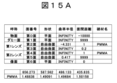
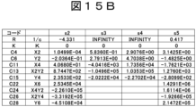
- FIG. 15A is composed of two free-form lenses, and Figure 15B shows the free-form surface coefficients (Equation 1).
- the incident light beam that enters these two free-form lenses and the converted outgoing light beam will be explained using Figures 16A and 16B.
- the size of the image plane is 3262 mm horizontal x 1010 mm vertical, which realizes the same ratio as the eye box 8 of 130 mm x 40 mm.
- the reason for leaving a gap of 10 m (Fig.
- FIG. 15A in front of and behind the free-form lens is to simply show the distribution of the exit angle of the light beam on the image plane in the spot diagram by separating the image plane to a distance where the height of the light beam at the free-form lens can be ignored compared to the height of the light beam on the image plane. Therefore, optical elements are arranged immediately before and after the actual free-form lens (microlens array 41) (Fig. 8). In this embodiment, a convex Fresnel lens is arranged on the reduction side, and a concave lens 10 is arranged on the enlargement side.
- Figure 16B shows the same incident light beam as Figure 16A, but shows the emitted light beam without the microlens array 41, and is also the incident light beam itself. Therefore, in Figure 16A, it can be seen that the emitted light beam has a large emission angle in the horizontal direction, and has a rectangular cross section in the horizontal and vertical directions.
- Figure 17 is a ray diagram at the YZ cross section and XZ cross section of a free-form lens, where the light beam at the entrance surface is circular and the light beam at the exit surface is elongated.
- the size of the light beam at the entrance surface and exit surface of the free-form lens is approximately the same because the cross-sectional area of the light beam at the YZ cross section and the XZ cross section between the entrance surface and exit surface of the microlens array 41 (free-form lens) is minimized, preventing the free-form lens from becoming too large.
- the light beam at the exit surface of the free-form lens is aligned into a vertically elongated shape, and the free-form surface at the exit surface greatly expands the horizontal diffusion angle, thereby achieving a horizontally elongated rectangular shape on the image plane.
- the microlens array 41 has a different radius of curvature in the XZ cross section and in the YZ cross section, and the diffusion angle in the X-axis direction is greater than the diffusion angle in the Y-axis direction.
- the divergence effect of each microlens of the microlens array 41 in the horizontal direction (X-axis direction) is greater than the divergence effect of each microlens of the microlens array 41 in the vertical direction (Y-axis direction).
- the "diffusion effect" in this invention may also be referred to as a "divergence effect.”
- the head-up display device of this embodiment includes a light source 1, a display panel 2, a relay optical system 3 that maps the image light emitted from the display panel 2, a diffusion element unit 4 that diffuses the image light mapped by the relay optical system 3, and a concave lens 10.
- a mirror 5 that reflects the light diffused by the diffusion element unit 4 and passing through the concave lens 10 may also be included.
- the mirror 5 the light reflected by the mirror 5 is projected onto a projection member such as a windshield 6 to display a virtual image.
- the mirror 5 is not included, the light emitted from the concave lens 10 is emitted onto a projection member such as a windshield 6 to display a virtual image.
- the diffusion element unit 4 includes a microlens array 41 having a plurality of microlenses, and the microlens array 41 has different optical effects in the horizontal and vertical directions of the microlens array 41, which correspond to the horizontal and vertical directions of the visual field range in which the virtual image can be observed.
- the optical performance of the projection optical system 20b can be ensured without increasing the number of lenses, making it possible to provide a compact head-up display device.
- the image display element 2 may be a reflective image display element in addition to a transmissive liquid crystal display panel.
- the optical design between the relay optical system 3 and the diffusion element section 4 can be telecentric, or a Fresnel lens can be placed immediately before the diffusion element section 4.
- the technology according to this embodiment can display navigation information such as destination and speed, as well as information necessary for driving such as alert information when an oncoming vehicle or pedestrian is detected, in line with the actual view through the windshield.
- This can prevent traffic accidents by providing an information display device (head-up display device) that reduces the driver's viewpoint movement and contributes to supporting safe driving. This contributes to "Good health and well-being for all," one of the Sustainable Development Goals (SDGs) advocated by the United Nations.
- SDGs Sustainable Development Goals
Landscapes
- Physics & Mathematics (AREA)
- Engineering & Computer Science (AREA)
- General Physics & Mathematics (AREA)
- Optics & Photonics (AREA)
- Chemical & Material Sciences (AREA)
- Combustion & Propulsion (AREA)
- Transportation (AREA)
- Mechanical Engineering (AREA)
- Instrument Panels (AREA)
Abstract
Description
本発明は、光学系、及びヘッドアップディスプレイ装置に関する。 The present invention relates to an optical system and a head-up display device.
自動車や航空機などの移動体が備える風防(ウインドシールド)に画像を投影し、その投影画像をウインドシールド越しに虚像として観察できるようにするヘッドアップディスプレイ装置が知られている。 Head-up display devices are known that project an image onto the windshield of a moving object such as an automobile or aircraft, allowing the projected image to be viewed as a virtual image through the windshield.
例えば、特許文献1には、従来のヘッドアップディスプレイ装置として、「透過型の液晶表示パネルの背後から光を照射して、液晶表示パネルに表示される画像を拡大投影する投影光学系を備える」装置が開示されている。
For example,
特許文献1に開示されたヘッドアップディスプレイ装置の例では、「リレーレンズによって結像された画像の拡大された実像」を投影レンズによりウインドシールドに投影することによって、運転者が虚像を観察している。すなわち、リレーレンズによって、液晶表示パネルの拡大した実像を得ることで、小型な液晶表示パネルを使用可能としている。
In the example of a head-up display device disclosed in
しかしながら、ヘッドアップディスプレイ装置での、液晶表示パネルの小型化には、通常の光学系の小型化とは異なる問題が存在する。図7A、図7B、図7Cを用いて説明する。 However, reducing the size of the LCD panel in a head-up display device poses problems that differ from those encountered when reducing the size of a normal optical system. These are explained using Figures 7A, 7B, and 7C.
図7A、図7B、図7Cは、映像表示素子2の小型化と投影光学系20bの関係を示す説明図である。図7A~図7Cおいて、投影光学系20bは、少なくともミラー5とウインドシールド6を含むものである。
FIGS. 7A, 7B, and 7C are explanatory diagrams showing the relationship between the miniaturization of the
図7Aは、基準となるサイズの映像表示素子2を示す図である。図7Aにおいて、基準となる映像表示素子2のサイズをAとしている。投影光学系20bの明るさF値は、F=(焦点距離)/(瞳径=アイボックス8の大きさ)=1/2/tan(θ/2)で定まる。図7Bは、小型の映像表示素子2の一例を示す図である。
FIG. 7A is a diagram showing an
図7Bは、図7Aを1/3倍に相似変形して小型化した図であり、映像表示素子2のサイズをA/3としている。図7Bの構成では、アイボックス8の大きさも小さくなるので、ヘッドアップディスプレイ装置30に必要なアイボックス8の大きさを確保することができない。図7Cは、小型の映像表示素子2の他の一例を示す図である。
FIG. 7B is a diagram of FIG. 7A miniaturized by being transformed to 1/3 the size, with the size of the
図7Cは、図7Bと同様に、映像表示素子2のサイズをA/3としているが、アイボックス8の大きさを図7Aと同じ大きさに戻した図である。図7Cの構成では、ヘッドアップディスプレイ装置30に必要なアイボックス8の大きさは確保できているが、投影光学系20bの明るさF値は、F=1/2/tan(3θ/2)となるので、大幅に明るい投影光学系20bが必要になる。
In Fig. 7C, like Fig. 7B, the size of the
即ち、液晶表示パネルを小型化すると、投影光学系の光学性能が大きく劣化する、或いは、光学性能を確保するために、より多くのレンズ枚数が必要になり、大型化するという問題がある。なお、映像表示素子2のみの小型化では、虚像も小さくなり、ヘッドアップディスプレイ装置の視野角が狭くなってしまう。
In other words, if the LCD panel is made smaller, the optical performance of the projection optical system will be significantly degraded, or a larger number of lenses will be required to ensure the optical performance, resulting in a problem of larger size. Furthermore, if only the
本発明は、上記した実情に鑑みてなされたものであり、小型なヘッドアップディスプレイ装置を提供することを目的とする。 The present invention was made in consideration of the above-mentioned circumstances, and aims to provide a small head-up display device.
上記課題を解決するために、代表的な本発明のヘッドアップディスプレイ装置の一つは、表示パネルと、表示パネルに光を供給する光源と、表示パネルから出射された映像光を写像するリレー光学系と、リレー光学系により写像された映像光を拡散する拡散素子部と、を備え、拡散素子部は、観視者の水平方向と垂直方向に対応する拡散素子部の水平方向と垂直方向で光学作用が異なる。 In order to solve the above problem, one representative head-up display device of the present invention includes a display panel, a light source that supplies light to the display panel, a relay optical system that maps the image light emitted from the display panel, and a diffusion element that diffuses the image light mapped by the relay optical system, and the diffusion element has different optical effects in the horizontal and vertical directions of the diffusion element that correspond to the horizontal and vertical directions of the viewer.
本発明によれば、小型なヘッドアップディスプレイ装置を提供することができる。なお、上記した以外の課題、構成及び効果は、以下の実施形態の説明により明らかにされる。 The present invention provides a small head-up display device. Problems, configurations, and advantages other than those described above will become clear from the description of the following embodiment.
以下、図面等を用いて、本発明の一実施形態及び各種実施例について説明する。以下の説明は本発明の内容の具体例を示すものであり、本発明がこれらの説明に限定されるものではなく、本明細書に開示される技術的思想の範囲内において当業者による様々な変更および修正が可能である。また、実施例を説明するための全図において、同一の機能を有するものは、同一の符号を付け、その繰り返しの説明は省略する場合がある。 Below, an embodiment of the present invention and various examples will be explained using drawings etc. The following explanations show specific examples of the contents of the present invention, and the present invention is not limited to these explanations. Various changes and modifications are possible by those skilled in the art within the scope of the technical ideas disclosed in this specification. Furthermore, in all figures used to explain the examples, parts having the same function are given the same reference numerals, and repeated explanations may be omitted.
図1を用いて、ヘッドアップディスプレイ装置30の基本構成について説明する。ヘッドアップディスプレイ装置は、表示装置、虚像表示装置等と称してもよい。
The basic configuration of the head-up
図1は、ヘッドアップディスプレイ装置30の概略構成図である。図1に示すヘッドアップディスプレイ装置30は、画像形成部と映像投射部を備える。本発明の実施形態において、画像形成部は光源1と映像表示素子または表示パネル2を有する。映像投射部はミラー5を備えていてもよい。光源1から映像表示素子または表示パネル2へ光が出射され、その後、表示パネル2からの映像光はミラー5へ入射され、ミラー5から出射された映像光を乗り物(例えば、図3の自動車500)のウインドシールド6で反射させて観察者の眼9に入射させる構成を備える。本発明では、乗り物のウインドシールド6へ映像光を投射することを用いて説明するが、映像光を投射する投射部はコンバイナなどの投射部材でもよい。この構成により、観察者の眼9から見ると、虚像面7において画像情報を見ているかのような状態になる。
1 is a schematic diagram of a head-up
本発明では、ミラー5は、映像表示素子または表示パネル2からの映像光を、設定された角度の方向または所定方向へ向けて拡大して反射する映像投射部として機能する。ミラー5は、例えば、凹面鏡(拡大鏡)であり、映像表示素子または表示パネル2とウインドシールド6との光路上に設けられる。ミラー5は、表示パネル2から出射された映像光をウインドシールド6に投射することで、投射された映像光を虚像として運転者等の利用者の眼9に視認させる映像光投射部として機能する。本実施例のミラー5は、凹面の反射面を有するミラーにより構成されている。
In the present invention, the
本実施例のヘッドアップディスプレイ装置の構成について図2を参照して説明する。 The configuration of the head-up display device of this embodiment will be explained with reference to Figure 2.
図2A及び図2Bは、本実施例のヘッドアップディスプレイ装置の構成および機能ブロック図である。図2A、図2Bに示すように、ヘッドアップディスプレイ装置は、表示パネル2と、光源1と、これらの動作を制御するコントローラー200と、を備えている。ヘッドアップディスプレイ装置は、さらにリレー光学系3と、拡散素子部4を備える。光源1から表示パネル2に光を照射し、表示パネル2に表示された画像情報(映像情報)をリレー光学系3、拡散素子部4を介してミラー5に向けて出射する。光源1、表示パネル2、リレー光学系3と、及び拡散素子部4を含むものは光学系と称してもよい。
2A and 2B are configuration and functional block diagrams of the head-up display device of this embodiment. As shown in FIGS. 2A and 2B, the head-up display device includes a
光源1は、代表的には、LED(Light Emitting Diode)光源を含んで構成され、複数個の光源を配列して用いてもよい。映像表示素子または表示パネル2は、代表的には、液晶パネル(Liquid Crystal Display:LCD)である。表示パネル2は、コントローラー200から指示され入力された映像データに基づいて、映像を作成し、当該表示パネル2の表示素子の表示面に表示する。なお、映像表示素子2は、液晶表示パネル、液晶表示素子、表示素子、表示パネル等と称してもよい。また、光源1はバックライトと称してもよい。
The
図2Aに示すように、本発明の実施の形態では、ヘッドアップディスプレイ装置30は、コントローラー200を備える装置となる。また、図2Bに示すように、コントローラー200を有さない場合には、自動車の制御部をコントローラー200として機能することも可能となる。自動車の制御部により制御する場合、ヘッドアップディスプレイ装置30のコントローラー200の制御とほぼ同じとなり、以下の実施の形態はヘッドアップディスプレイ装置30のコントローラー200を用いて説明する。すなわち、ヘッドアップディスプレイ装置30がコントローラー200を備えていてもよいし、自動車のような外部に備えられた制御装置を用いてもよい。
As shown in FIG. 2A, in an embodiment of the present invention, the head-up
このコントローラー200には、種々の情報が外部装置から入力される。例えば、ヘッドアップディスプレイ装置30を搭載した移動体の動作に関する情報を生成して出力するナビゲーション装置であるナビ208や、移動体の動作を制御するECU(Electronic Control Unit)209が接続されている。ECU209には移動体が備える各種のセンサ210が接続されていて、検知した情報をECU209に通知するように構成されている。
Various types of information are input to this
コントローラー200は、上記にて説明をした外部装置からの各種データを処理するマイコン202と、マイコン202に接続された記憶装置206と、バックライト1を駆動するためのバックライト駆動回路207と、を備えている。
The
マイコン202は、外部装置からの各種データを記憶するためのRAM(Random Access Memory)203と、観察者が視認する虚像の元になる画像データを生成する演算処理を実行するCPU(Central Processing Unit)205と、CPU205における演算処理を実行可能なプログラムやパラメータを記憶するROM(Read Only Memory)204と、を備えている。 The microcomputer 202 is equipped with a RAM (Random Access Memory) 203 for storing various data from external devices, a CPU (Central Processing Unit) 205 for performing calculations to generate image data that is the basis of the virtual image viewed by the observer, and a ROM (Read Only Memory) 204 for storing programs and parameters that can execute the calculations in the CPU 205.
以上の構成を備えるコントローラー200によって映像表示素子2に画像情報が表示される。映像表示素子2に表示された画像情報をバックライト1が照射した光によってリレー光学系3と、拡散素子部4とを介して映像光としてミラー5に向けて出射する。
The
図1に戻る。表示パネル2から出射された映像光は、ミラー5によって、ウインドシールド6に投射される。ミラー5からウインドシールド6に投射された映像光は、ウインドシールド6で反射されて、観察者の眼9の位置に到達する。これによって、観察者の眼9から見ると、あたかも、虚像面7の画像情報を見ているような関係性が成立する。なお、ミラー5を備えていない場合、表示パネル2からの映像光は、ウインドシールド6へ出射され、ウインドシールド6に出射された映像光は、ウインドシールド6で反射されて、観察者の眼9の位置に到達する。
Returning to FIG. 1, the image light emitted from the
図1のように、映像表示素子2における映像光の出射面において、点P1・点P2・点P3という仮想点を考える。これら仮想点から出射された映像光がリレー光学系3により、拡散素子部4の点Q1・点Q2・点Q3に写像される。点Q1・点Q2・点Q3から出射された映像光が対応する虚像面7における仮想点を考えると、図1に示すように点V1・点V2・点V3が、それに当たる。
As shown in Figure 1, consider virtual points P1, P2, and P3 on the emission surface of the image light on the
観察者が眼9の位置を動かしても虚像面7における点V1・点V2・点V3を視認できる範囲が、アイボックス8である。このように、リレー光学系3、拡散素子部4、ミラー5を含むものは、物(空間像)の像(虚像)を観察者の眼9の前に表示する投影光学系または投射光学系と称してもよい。なお、投影光学系または投射光学系はミラー5を含んでいなくてもよい。
The
ここで、本実施形態に係るヘッドアップディスプレイ装置30を乗り物または移動体に搭載した場合の例について図3を用いて説明する。
Here, an example of a case where the head-up
図3は、ヘッドアップディスプレイ装置30を搭載した移動体である自動車500を前方から見た平面図である。図3に示すような自動車500には、風防としてフロントガラスであるウインドシールド6が、運転席の前方に配置されている。
FIG. 3 is a plan view of an
ヘッドアップディスプレイ装置30は、ウインドシールド6に映像光を投射することで、自動車500に関連する各種情報を運転者及び自動車500にいる観察者が虚像として視認できる状態にする。映像光が投射される位置は、運転席の前方やその周囲である。例えば、破線矩形領域R1に示すような位置に映像光が投射される。
The head-up
次に、本実施の形態における映像表示素子2を小型化するための基本構成について、図4A~図4Cを用いて説明する。図4A~図4Cにおいて、投影光学系20bは、ミラー5(図2A)を含むものである。ミラー5は本実施形態では凹面ミラーであり、集光作用を持つので凸レンズと同じ作用に相当する。しかし、投影光学系20bは凸レンズではなく、光学部品としては、ミラー5に加えて凹レンズなどの場合もある。また、リレー光学系も同じでフィールドレンズを含む複数のレンズで構成されてもよい。なお、θを用いることで光学系の明るさを表すF値が、F=1/2/tan(θ/2)で定まる。F値が小さい程明るい、つまりθが大きい程明るい。
Next, the basic configuration for miniaturizing the
図4Aは、基準サイズの映像表示素子2を使用した構成を示す図である。図4Aでは、基準となる映像表示素子2のサイズをAとしている。θを用いることで光学系の明るさを表すF値は、F=(焦点距離)/(瞳径=アイボックス8の大きさ)=1/2/tan(θ/2)で定まる。F値が小さい程明るい、つまりθが大きい程明るい。
Fig. 4A is a diagram showing a configuration using an
図4Bは、小型の映像表示素子2とリレー光学系3とスクリーン板4bを使用した構成を示す図である。図4Bでは、映像表示素子2のサイズをA/3としている。図4Bでは、倍率3倍のリレー光学系3を用いてスクリーン板4bに写像することで、アイボックス8の大きさを確保する構成としている。リレー光学系3のスクリーン板4b側の角度がθ、リレー光学系3の映像表示素子2側の角度が3θで、F値がF=1/2/tan(3θ/2)であるので、リレー光学系3が非常に大口径になっている。
Fig. 4B is a diagram showing a configuration using a small
図4Cは、小型の映像表示素子2とリレー光学系3と拡散素子部4を使用した構成を示す図である。図4Cでは、映像表示素子2のサイズをA/3としているが、リレー光学系3の映像表示素子2側の角度をθのままとし、リレー光学系3の拡散素子部4側の角度をθ/3とし、拡散素子部4で映像光を拡散することで、アイボックス8の大きさを確保する構成としている。図4Cにおける角度θは、映像表示素子2からリレー光学系3の上部に入射する光とリレー光学系3の下部に入射する光からなる。
Fig. 4C is a diagram showing a configuration using a small
図4Cの構成によれば、リレー光学系3を大型化することなく、小型の映像表示素子2を使用することができる。この拡散素子部4の詳細について、図5A~図5Cを用いて説明する。なお、乗り物または運転者または観視者に対して、X軸は、水平方向、左右方向、乗り物の横方向または乗り物の幅方向であり、Y軸は、乗り物の上下方向、鉛直方向、縦方向であり、乗り物の横方向に対し直交するZ軸は、乗り物の前後方向または乗り物の進行方向である。
The configuration of Fig. 4C makes it possible to use a small
図5A~図5Cにおいて、X軸とY軸は、観察者が観察可能な視野範囲(アイボックス8)のそれぞれ、水平方向と垂直方向に対応する。水平方向は、左右の眼の距離の分、観察範囲が大きくなる。例えば、アイボックス8は水平130mm×垂直50mmなどである。従って、拡散素子部4のX軸方向に相当する側の方が、Y軸方向に相当する側と比較して、大きな観察範囲が必要である。また、マイクロレンズがシリンダレンズ(シリンドリカルレンズ)の場合は、特定の方向、例えば、マイクロレンズアレイ41の光入射側は左または右から、マイクロレンズアレイ41の光出射側は上または下から見るときだけ、シリンダレンズの曲率半径が見える。
In Figures 5A to 5C, the X-axis and Y-axis correspond to the horizontal and vertical directions of the field of view (eye box 8) that the observer can observe. In the horizontal direction, the observation range is larger by the distance between the left and right eyes. For example, the
図5Aではマイクロレンズアレイ41の光入射側が平面であり、マイクロレンズアレイ41の光出射側が垂直方向と水平方向に拡散作用を行う。図5Bでは、マイクロレンズアレイ41の光入射側がY軸方向(垂直方向)に拡散作用を行い、マイクロレンズアレイ41の光出射側がX軸方向(水平方向)に拡散作用を行う。図5Cは、マイクロレンズアレイ41の光入射側は平面で、マイクロレンズアレイ41の光出射側が水平方向に拡散作用を行う。 In Figure 5A, the light incident side of the microlens array 41 is flat, and the light exit side of the microlens array 41 diffuses light in the vertical and horizontal directions. In Figure 5B, the light incident side of the microlens array 41 diffuses light in the Y-axis direction (vertical direction), and the light exit side of the microlens array 41 diffuses light in the X-axis direction (horizontal direction). In Figure 5C, the light incident side of the microlens array 41 is flat, and the light exit side of the microlens array 41 diffuses light in the horizontal direction.
図5A(1)~図5A(3)は、拡散素子部4の構成の一例を示す図である。図5Aにおいて、拡散素子部4は、マイクロレンズアレイ41と遮光格子42aを備える。遮光格子とマイクロレンズアレイは、接着または保持部などを介して配置されている。マイクロレンズアレイ41は、一つまたは複数のマイクロレンズを有する。遮光格子42aは一つ以上の開口部を有し、マイクロレンズアレイ41の光出射側に配置されている。また、マイクロレンズアレイ41は、遮光格子42aの開口部に対応する。一つのマイクロレンズは一つの開口に対応してもよいし、1つ以上のマイクロレンズは一つの開口に対応してもよいし、特に限定されない。つまり、遮光格子は開口部を有し、開口部は一つ以上の開口を有し、開口は少なくとも一つのマイクロレンズに対応する。本実施形態では、マイクロレンズアレイに応じて、遮蔽作用を行うための遮光格子の開口部が配置される。映像表示素子2の各画素は、リレー光学系3で写像したマイクロレンズアレイ41の各セルに対応している。
5A(1) to 5A(3) are diagrams showing an example of the configuration of the
図5Aは、マイクロレンズアレイ41の光入射側が平面で、マイクロレンズアレイ41の光出射側が垂直方向と水平方向に拡散作用を行っている。マイクロレンズアレイ41は、XZ断面での曲率半径とYZ断面での曲率半径が異なり、X軸方向の拡散角度がY軸方向の拡散角度より大きい。つまり、マイクロレンズアレイ41の各マイクロレンズの水平方向(X軸方向)の発散作用はマイクロレンズアレイ41の各マイクロレンズの垂直方向(Y軸方向)の発散作用よりも大きい。なお、本発明における「拡散作用」は「発散作用」と称してもよい。 In FIG. 5A, the light incident side of the microlens array 41 is flat, and the light exit side of the microlens array 41 diffuses light in both the vertical and horizontal directions. The microlens array 41 has different radii of curvature in the XZ cross section and the YZ cross section, and the diffusion angle in the X-axis direction is greater than the diffusion angle in the Y-axis direction. In other words, the divergence effect of each microlens of the microlens array 41 in the horizontal direction (X-axis direction) is greater than the divergence effect of each microlens of the microlens array 41 in the vertical direction (Y-axis direction). Note that the "diffusion effect" in this invention may also be referred to as a "divergence effect".
マイクロレンズには、例えば、トロイダルレンズや自由曲面レンズなどが適用可能である。遮光格子42aの各開口は、マイクロレンズアレイ41の各レンズに対応し、リレー光学系3で写像したマイクロレンズアレイ41の各セルでの光の集光像(スポット)のうち、各セルの周辺部まで広がった光を遮光している。パネルサイズや解像度で異なるが、例えば、映像表示素子2の各画素の開口率は、50%程度なので、倍率以上に広がったリレー光学系3の光束を遮光することで、解像度の劣化を防いでいる。
For example, a toroidal lens or a free-form lens can be used as the microlens. Each opening of the light-shielding grid 42a corresponds to each lens of the microlens array 41, and blocks light that spreads to the periphery of each cell in the focused image (spot) of light in each cell of the microlens array 41 mapped by the relay
図5B(1)~図5B(4)は、拡散素子部4の構成の他の一例を示す図である。図5Aの遮光格子42aはマイクロレンズアレイ41の光出射側に配置されているが、図5Bでは、マイクロレンズアレイ41の光入射側に遮光格子42c、マイクロレンズアレイ41の光出射側に遮光格子42bを配置している。なお、遮光格子とマイクロレンズアレイは、接着または構造物などを介して配置されている。
Fig. 5B(1) to Fig. 5B(4) are diagrams showing another example of the configuration of the
図5Bのマイクロレンズアレイ41は、光入射側のマイクロレンズでY軸方向の拡散作用を行い、光出射側のマイクロレンズでX軸方向の拡散作用を行っている。X軸方向に対しては遮光格子42bを配置し、Y軸方向に対しては遮光格子42cを配置している。あるいは、図5Bは、マイクロレンズアレイ41の光入射側が垂直方向に拡散作用を行い、マイクロレンズアレイ41の光出射側が水平方向に拡散作用を行っている。また、図5Bは拡散作用の方向に対して遮光格子を配置するものであるが、図5Aの遮光格子42aを用いてもよい。 In the microlens array 41 of FIG. 5B, the microlenses on the light incident side diffuse light in the Y-axis direction, and the microlenses on the light exit side diffuse light in the X-axis direction. A light-shielding grating 42b is arranged in the X-axis direction, and a light-shielding grating 42c is arranged in the Y-axis direction. Alternatively, in FIG. 5B, the light incident side of the microlens array 41 diffuses light in the vertical direction, and the light exit side of the microlens array 41 diffuses light in the horizontal direction. Also, while FIG. 5B shows a light-shielding grating arranged in the direction of diffusion, the light-shielding grating 42a of FIG. 5A may also be used.
図5C(1)~図5C(3)は、拡散素子部4の構成の他の一例を示す図である。図5Cのマイクロレンズアレイ41は、X軸方向のみに曲率半径を有する形状であり、例えば、シリンダレンズのアレイや、自由曲面レンズアレイなどが適用可能である。図5Cでは、マイクロレンズアレイ41の入射側が平面で、マイクロレンズアレイ41の出射側は水平方向に拡散作用を行う。図5Cのマイクロレンズアレイ41ではX軸方向のみに拡散作用がある。つまり、マイクロレンズアレイ41の各マイクロレンズが水平方向(X軸)のみで発散作用を有する。よって、図5Cでは、光出射側にY軸方向のみに遮蔽作用を有する遮光格子42bを配置している。
FIGS. 5C(1) to 5C(3) are diagrams showing another example of the configuration of the
図5Cの遮光格子42bは、Y軸方向のみに遮蔽作用を有する形状でもよいし、図5Aの遮光格子42aを用いてもよい。また、図5A~図5Cに示すマイクロレンズアレイ41は、光入射側と光出射側で異なる発散作用を有するように構成されてもよい。
なお、図5A~図5Cにおいて、拡散素子部4は、マイクロレンズアレイ41と遮光格子42a,42b,42cを一体の構造(保持)としてもよい。マイクロレンズアレイ41の各マイクロレンズは、拡散素子部の光入射面側と光出射面側の少なくとも一方に拡散作用を有してもよい。また、リレー光学系3と拡散素子部4の間では、テレセントリックで光学設計を行う、或いは、レンチキュラーレンズを拡散素子部4の直前に配置することでもよい。
The light-shielding grating 42b in Fig. 5C may have a shape that has a shielding effect only in the Y-axis direction, or the light-shielding grating 42a in Fig. 5A may be used. Also, the microlens array 41 shown in Figs. 5A to 5C may be configured to have different divergence effects on the light incident side and the light exit side.
5A to 5C, the
次に、拡散素子部4のマイクロレンズアレイ41での映像光の拡散作用について、図6A~図6Dを用いて説明する。図6A~図6Dは、リレー光学系3の側から、マイクロレンズアレイ41に映像光が入射した状態を表している。
Next, the diffusion effect of the image light in the microlens array 41 of the
図6Aは、マイクロレンズを使用しない場合の映像光の拡散を示す図である。図6Aは基準として、マイクロレンズアレイ41を使用しない場合であり、映像表示素子側またはリレー光学系側とEyebox側との映像光の形状がほぼ同じである。 FIG. 6A is a diagram showing the diffusion of image light when no microlenses are used. FIG. 6A shows the case where the microlens array 41 is not used as a reference, and the shape of the image light on the image display element side or relay optical system side is approximately the same as that on the Eyebox side.
図6Bは、マイクロレンズを使用した場合の映像光の拡散の一例を示す図である。図6Bでは、リレー光学系3の集光位置の手前に正の屈折力を有するマイクロレンズアレイ41を配置することで、映像光が拡散する角度を大きくしている。
FIG. 6B is a diagram showing an example of the diffusion of image light when a microlens is used. In FIG. 6B, a microlens array 41 with positive refractive power is placed in front of the focusing position of the relay
図6Cは、マイクロレンズを使用した場合の映像光の拡散の他の一例を示す図である。図6Cでは、リレー光学系3の集光位置の手前に正の屈折力を有し、集光位置の後に負の屈折力を有するマイクロレンズアレイ41を配置することで、映像光が拡散する角度をさらに大きくしている。
FIG. 6C is a diagram showing another example of diffusion of image light when microlenses are used. In FIG. 6C, a microlens array 41 with positive refractive power is placed in front of the focusing position of the relay
図6Dは、マイクロレンズを使用した場合の映像光の拡散の他の一例を示す図である。図6Dでは、リレー光学系3の集光位置の後に負の屈折力を偏心させるマイクロレンズアレイ41を配置することで、映像光を拡散する角度を大きくすると共に、光を斜めに出射している。なお、図6Dにおいて、マイクロレンズアレイ41の各マイクロレンズは、偏心レンズであってもよい。
FIG. 6D is a diagram showing another example of diffusion of image light when microlenses are used. In FIG. 6D, a microlens array 41 with a decentered negative refractive power is placed after the focusing position of the relay
本実施形態のヘッドアップディスプレイ装置では、光源1と、表示パネル2と、表示パネル2から出射された映像光を写像するリレー光学系3と、リレー光学系3により写像された映像光を拡散する拡散素子部4と、を備える。さらに拡散素子部4によって拡散された映像光を反射するミラー5を備えてもよい。ミラー5を備える場合は、ミラー5で反射された光をウインドシールド6等の投射部材に投射して虚像を表示させる。ミラー5を備えない場合は、拡散素子部4によって拡散された映像光をウインドシールド6等の投射部材に出射して虚像を表示させる。拡散素子部4は、複数のマイクロレンズを有するマイクロレンズアレイ41を備え、マイクロレンズアレイ41は、虚像を観察可能な視野範囲の水平方向と垂直方向に対応するマイクロレンズアレイ41の水平方向と垂直方向で光学作用が異なる。
The head-up display device of this embodiment includes a
これにより、本実施形態によれば、映像表示素子2を小型化しても、レンズ枚数を増やすことなく投影光学系20bの光学性能を確保することができ、小型なヘッドアップディスプレイ装置を提供することができる。
As a result, according to this embodiment, even if the
なお、映像表示素子2としては、透過型の液晶表示パネルの他に、反射型映像表示素子などでもよい。
In addition, the
また、リレー光学系3と拡散素子部4の間では、テレセントリックで光学設計を行う、或いは、レンチキュラーレンズを拡散素子部4の直前に配置することでもよい。
Furthermore, between the relay
<他の実施例>
図8を用いて、ヘッドアップディスプレイ装置30の基本構成について説明する。ヘッドアップディスプレイ装置は、表示装置、虚像表示装置等と称してもよい。
<Other Examples>
A basic configuration of the head-up
図8は、ヘッドアップディスプレイ装置30の概略構成図である。図8に示すヘッドアップディスプレイ装置30は、画像形成部と映像投射部を備える。本発明の実施形態において、画像形成部は光源1と映像表示素子または表示パネル2を有する。映像投射部は凹レンズ10とミラー5を備えていてもよい。光源1から映像表示素子または表示パネル2へ光が出射され、その後、表示パネル2からの映像光はミラー5へ入射され、ミラー5から出射された映像光を乗り物(例えば、図3の自動車500)のウインドシールド6で反射させて観察者の眼9に入射させる構成を備える。本発明では、乗り物のウインドシールド6へ映像光を投射することを用いて説明するが、映像光を投射する投射部はコンバイナなどの投射部材でもよい。この構成により、観察者の眼9から見ると、虚像面7において画像情報を見ているかのような状態になる。
8 is a schematic diagram of a head-up
本発明では、ミラー5は、映像表示素子または表示パネル2からの映像光を、設定された角度の方向または所定方向へ向けて拡大して反射する映像投射部として機能する。ミラー5は、例えば、凹面鏡(拡大鏡)であり、映像表示素子または表示パネル2とウインドシールド6との光路上に設けられる。ミラー5は、表示パネル2から出射された映像光をウインドシールド6に投射することで、投射された映像光を虚像として運転者等の利用者の眼9に視認させる映像光投射部として機能する。本実施例のミラー5は、凹面の反射面を有するミラーにより構成されている。なお、ミラー5は反射素子、反射ミラー等と称してもよい。
In the present invention, the
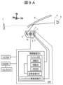
本実施例のヘッドアップディスプレイ装置の構成について図9A、図9Bを参照して説明する。 The configuration of the head-up display device of this embodiment will be described with reference to Figures 9A and 9B.
図9A及び図9Bは、本実施例のヘッドアップディスプレイ装置の構成および機能ブロック図である。図9A、図9Bに示すように、ヘッドアップディスプレイ装置は、表示パネル2と、光源1と、これらの動作を制御するコントローラー200と、を備えている。ヘッドアップディスプレイ装置は、さらにリレー光学系3と、拡散素子部4と、凹レンズ10を備える。光源1から表示パネル2に光を照射し、表示パネル2に表示された画像情報(映像情報)をリレー光学系3、拡散素子部4、凹レンズ10を介してミラー5に向けて出射する。光源1、表示パネル2、リレー光学系3と、及び拡散素子部4と、凹レンズ10を含むものは光学系と称してもよい。
9A and 9B are configuration and functional block diagrams of the head-up display device of this embodiment. As shown in FIGS. 9A and 9B, the head-up display device includes a
光源1は、代表的には、LED(Light Emitting Diode)光源を含んで構成され、複数個の光源を配列して用いてもよい。映像表示素子または表示パネル2は、代表的には、液晶パネル(Liquid Crystal Display:LCD)である。表示パネル2は、コントローラー200から指示され入力された映像データに基づいて、映像を作成し、当該表示パネル2の表示素子の表示面に表示する。なお、映像表示素子2は、液晶表示パネル、液晶表示素子、表示素子、表示パネル等と称してもよい。また、光源1はバックライトと称してもよい。凹レンズ10は光学素子と称してもよい。
The
図9Aに示すように、本発明の実施の形態では、ヘッドアップディスプレイ装置30は、コントローラー200を備える装置となる。また、図9Bに示すように、コントローラー200を有さない場合には、自動車の制御部をコントローラー200として機能することも可能となる。自動車の制御部により制御する場合、ヘッドアップディスプレイ装置30のコントローラー200の制御とほぼ同じとなり、以下の実施の形態はヘッドアップディスプレイ装置30のコントローラー200を用いて説明する。すなわち、ヘッドアップディスプレイ装置30がコントローラー200を備えていてもよいし、自動車のような外部に備えられた制御装置を用いてもよい。
As shown in FIG. 9A, in an embodiment of the present invention, the head-up
このコントローラー200には、種々の情報が外部装置から入力される。例えば、ヘッドアップディスプレイ装置30を搭載した移動体の動作に関する情報を生成して出力するナビゲーション装置であるナビ208や、移動体の動作を制御するECU(Electronic Control Unit)209が接続されている。ECU209には移動体が備える各種のセンサ210が接続されていて、検知した情報をECU209に通知するように構成されている。
Various types of information are input to this
コントローラー200は、上記にて説明をした外部装置からの各種データを処理するマイコン202と、マイコン202に接続された記憶装置206と、バックライト1を駆動するためのバックライト駆動回路207と、を備えている。
The
マイコン202は、外部装置からの各種データを記憶するためのRAM(Random Access Memory)203と、観察者が視認する虚像の元になる画像データを生成する演算処理を実行するCPU(Central Processing Unit)205と、CPU205における演算処理を実行可能なプログラムやパラメータを記憶するROM(Read Only Memory)204と、を備えている。 The microcomputer 202 is equipped with a RAM (Random Access Memory) 203 for storing various data from external devices, a CPU (Central Processing Unit) 205 for performing calculations to generate image data that is the basis of the virtual image viewed by the observer, and a ROM (Read Only Memory) 204 for storing programs and parameters that can execute the calculations in the CPU 205.
以上の構成を備えるコントローラー200によって映像表示素子2に画像情報が表示される。映像表示素子2に表示された画像情報をバックライト1が照射した光によってリレー光学系3と、拡散素子部4と、凹レンズ10とを介して映像光としてミラー5に向けて出射する。
The
図8に戻る。表示パネル2から出射された映像光は、ミラー5によって、ウインドシールド6に投射される。ミラー5からウインドシールド6に投射された映像光は、ウインドシールド6で反射されて、観察者の眼9の位置に到達する。これによって、観察者の眼9から見ると、あたかも、虚像面7の画像情報を見ているような関係性が成立する。なお、ミラー5を備えていない場合、表示パネル2からの映像光は、ウインドシールド6へ出射され、ウインドシールド6に出射された映像光は、ウインドシールド6で反射されて、観察者の眼9の位置に到達する。
Returning to Figure 8, the image light emitted from the
図8のように、映像表示素子2における映像光の出射面において、点P1・点P2・点P3という仮想点を考える。これら仮想点から出射された映像光がリレー光学系3により、拡散素子部4の点Q1・点Q2・点Q3に写像される。点Q1・点Q2・点Q3から出射された映像光が対応する虚像面7における仮想点を考えると、図8に示すように点V1・点V2・点V3が、それに当たる。
As shown in Figure 8, consider virtual points P1, P2, and P3 on the emission surface of the image light on the
観察者が眼9の位置を動かしても虚像面7における点V1・点V2・点V3を視認できる範囲が、アイボックス8である。このように、リレー光学系3、拡散素子部4、凹レンズ10、ミラー5を含むものは、物(空間像)の像(虚像)を観察者の眼9の前に表示する投影光学系または投射光学系と称してもよい。なお、投影光学系または投射光学系はミラー5を含んでいなくてもよい。
The
ここで、本実施形態に係るヘッドアップディスプレイ装置30を乗り物または移動体に搭載した場合の例について図3を用いて説明する。
Here, an example of a case where the head-up
図3は、ヘッドアップディスプレイ装置30を搭載した移動体である自動車500を前方から見た平面図である。図3に示すような自動車500には、風防としてフロントガラスであるウインドシールド6が、運転席の前方に配置されている。
FIG. 3 is a plan view of an
ヘッドアップディスプレイ装置30は、ウインドシールド6に映像光を投射することで、自動車500に関連する各種情報を運転者及び自動車500にいる観察者が虚像として視認できる状態にする。映像光が投射される位置は、運転席の前方やその周囲である。例えば、破線矩形領域R1に示すような位置に映像光が投射される。
The head-up
次に、本実施の形態における映像表示素子2を小型化するための基本構成について、図4A~図4Cを用いて説明する。図4A~図4Cにおいて、投影光学系20bは、ミラー5(図9A)を含むものである。ミラー5は本実施形態では凹面ミラーであり、集光作用を持つので凸レンズと同じ作用に相当する。しかし、投影光学系20bは凸レンズではなく、光学部品としては、ミラー5に加えて凹レンズなどの場合もある。また、リレー光学系3も同じでフィールドレンズを含む複数のレンズで構成されてもよい。なお、θを用いることで光学系の明るさを表すF値が、F=1/2/tan(θ/2)で定まる。F値が小さい程明るい、つまりθが大きい程明るい。
Next, the basic configuration for miniaturizing the
図4Aは、基準サイズの映像表示素子2を使用した構成を示す図である。図4Aでは、基準となる映像表示素子2のサイズをAとしている。θを用いることで光学系の明るさを表すF値は、F=(焦点距離)/(瞳径=アイボックス8の大きさ)=1/2/tan(θ/2)で定まる。F値が小さい程明るい、つまりθが大きい程明るい。
Fig. 4A is a diagram showing a configuration using an
図4Bは、小型の映像表示素子2とリレー光学系3とスクリーン板4bを使用した構成を示す図である。図4Bでは、映像表示素子2のサイズをA/3としている。図4Bでは、倍率3倍のリレー光学系3を用いてスクリーン板4bに写像することで、アイボックス8の大きさを確保する構成としている。リレー光学系3のスクリーン板4b側の角度がθ、リレー光学系3の映像表示素子2側の角度が3θで、F値がF=1/2/tan(3θ/2)であるので、リレー光学系3が非常に大口径になっている。
Fig. 4B is a diagram showing a configuration using a small
図4Cは、小型の映像表示素子2とリレー光学系3と拡散素子部4を使用した構成を示す図である。図4Cでは、映像表示素子2のサイズをA/3としているが、リレー光学系3の映像表示素子2側の角度をθのままとし、リレー光学系3の拡散素子部4側の角度をθ/3とし、拡散素子部4で映像光を拡散することで、アイボックス8の大きさを確保する構成としている。図4Cにおける角度θは、映像表示素子2からリレー光学系3の上部に入射する光とリレー光学系3の下部に入射する光からなる。
Fig. 4C is a diagram showing a configuration using a small
図4Cの構成によれば、リレー光学系3を大型化することなく、小型の映像表示素子2を使用することができる。この拡散素子部4の詳細について、図10~図17を用いて説明する。なお、乗り物または運転者または観視者に対して、X軸は、水平方向、左右方向、乗り物の横方向または乗り物の幅方向であり、Y軸は、乗り物の上下方向、鉛直方向、縦方向であり、乗り物の横方向に対し直交するZ軸は、乗り物の前後方向または乗り物の進行方向である。
The configuration of Fig. 4C makes it possible to use a small
図10において、X軸とY軸は、観察者が観察可能な視野範囲(アイボックス8)のそれぞれ、水平方向と垂直方向に対応する。水平方向は、左右の眼の距離の分、観察範囲が大きくなる。例えば、アイボックス8は水平130mm×垂直50mmなどである。従って、拡散素子部4のX軸方向に相当する側の方が、Y軸方向に相当する側と比較して、大きな観察範囲が必要である。
In FIG. 10, the X-axis and Y-axis correspond to the horizontal and vertical directions of the field of view (eye box 8) that the observer can observe. In the horizontal direction, the observation range is larger by the distance between the left and right eyes. For example, the
図10(1)ではマイクロレンズアレイ41の光入射側の凸面と、マイクロレンズアレイ41の光出射側の凹面で、拡散作用を行っている。マイクロレンズアレイ41の光入射側に遮光格子42aを配置し、マイクロレンズアレイ41の光出射側に遮光格子42bを配置している。図10(2)の遮光格子42aの各開口部に、マイクロレンズアレイ41の各セルが対応している。遮光格子42aの各開口部は、マイクロレンズアレイ41の各マイクロレンズに対応し、リレー光学系3で写像したマイクロレンズアレイ41の各セルでの光の集光像(スポット)のうち、各セルの周辺部まで広がった光を遮光している。パネルサイズや解像度で異なるが、例えば、映像表示素子2の各画素の開口率は、50%程度なので、倍率以上に広がったリレー光学系3の光束を遮光することで、解像度の劣化を防いでいる。
In FIG. 10(1), the convex surface on the light incident side of the microlens array 41 and the concave surface on the light exit side of the microlens array 41 perform the diffusion effect. A light-shielding grating 42a is arranged on the light incident side of the microlens array 41, and a light-shielding grating 42b is arranged on the light exit side of the microlens array 41. Each cell of the microlens array 41 corresponds to each opening of the light-shielding grating 42a in FIG. 10(2). Each opening of the light-shielding grating 42a corresponds to each microlens of the microlens array 41, and blocks light that spreads to the periphery of each cell from the focused image (spot) of light in each cell of the microlens array 41 mapped by the relay
なお、遮光格子とマイクロレンズアレイは、接着または構造物などを介して配置されている。図10において、拡散素子部4は、マイクロレンズアレイ41と遮光格子42a、42bを一体の構造(保持)としてもよい。また、リレー光学系3と拡散素子部4の間では、テレセントリックで光学設計を行う、或いは、フレネルレンズを拡散素子部4の直前に配置することでもよい。リレー光学系3もテレセントリックの光学設計によって、マイクロレンズアレイ41の各マイクロレンズには、同じ条件の光束が入射する。
The light-shielding grating and the microlens array are arranged by bonding or via a structure. In FIG. 10, the
次に、断面形状が円形形状の入射光束を、アイボックス8に合わせて、断面形状が矩形形状の出射光束に変換するために、マイクロレンズアレイ41のX軸方向(水平方向)とY軸方向(垂直方向)で異なる拡散作用を実現するための、基本的な考え方について、図11Aと図11Bを用いて説明する。
Next, the basic idea of achieving different diffusion effects in the X-axis direction (horizontal direction) and Y-axis direction (vertical direction) of the microlens array 41 in order to convert an incident light beam with a circular cross-sectional shape into an outgoing light beam with a rectangular cross-sectional shape to match the
図11Aは、図10(1)のマイクロレンズアレイ41のマイクロレンズごとの入射光束の断面図であり、代表点にA0~A5を割り当てたマッピングを示す図である。同様に、図11Bは、図10(1)のマイクロレンズアレイ41のマイクロレンズごとの出射光束の断面図であり、代表点にB0~B5を割り当てたマッピングを示す図である。円形形状を矩形形状に変換するので左右対称と上下対称なので、図11Aの断面図では、中心点をA0とし、第1象限(図でα=0~90度の範囲)で光束の外周部に等間隔にA1~A5を配置している。同様に、左右対称と上下対称なので、図11Bの断面図では、中心点をB0とし、第3象限(図でα=180~270度の範囲)で光束の外周部に等間隔にB1~B5を配置している。図11Aと図11Bとで配置箇所が異なるのは、マイクロレンズアレイ41の中で光束が集光しているので、入射光線と出射光線とでは、X軸上の値の符号が反転し、かつ、Y軸上の値の符号が反転しているからである。 FIG. 11A is a cross-sectional view of the incident light beams for each microlens of the microlens array 41 in FIG. 10(1), and shows a mapping in which A0 to A5 are assigned to representative points. Similarly, FIG. 11B is a cross-sectional view of the exiting light beams for each microlens of the microlens array 41 in FIG. 10(1), and shows a mapping in which B0 to B5 are assigned to representative points. Since the circular shape is converted into a rectangular shape, it is symmetrical from left to right and from top to bottom, so in the cross-sectional view of FIG. 11A, the center point is A0, and A1 to A5 are arranged at equal intervals on the outer periphery of the light beam in the first quadrant (α = 0 to 90 degrees in the figure). Similarly, since it is symmetrical from left to right and from top to bottom, in the cross-sectional view of FIG. 11B, the center point is B0, and B1 to B5 are arranged at equal intervals on the outer periphery of the light beam in the third quadrant (α = 180 to 270 degrees in the figure). The reason why the placement locations are different in Figures 11A and 11B is that the light beam is focused inside the microlens array 41, so the signs of the values on the X-axis are reversed between the incident light beam and the outgoing light beam, and the signs of the values on the Y-axis are reversed.
ところで、断面が円形形状の入射光束を、アイボックス8に合わせて、断面が矩形形状の出射光束に変換する際に、光線密度をほぼ一定に変換すると、明るさに大きなムラが発生しにくくなる。そこで、円形形状から切り出す面積比と、対応させる矩形形状の面積比を合わせることが必要である。上下対称、左右対称なので、図11Aの円形状の4分割(円弧A1~A5と点A0で切り出した円の面積)と、図11Bの矩形形状の4分割(外周B1~B5と点B0で切り出した矩形の面積)を対応させために、入射光束の断面での点A0を出射光束の断面での点B0に対応させ、点A1を点B1に対応させ、点A5を点B5に対応させる。
When converting an incident light beam with a circular cross section into an exiting light beam with a rectangular cross section to fit the
次に、図11Aでα=45度に点A3を設け、線分A0-A3で4分割をさらに2分割することで、元の円形形状の面積の8分割になる。図11Bでも矩形形状の対角部に点B3を設け、線分B0-B3で4分割をさらに2分割することで、元の矩形形状の面積の8分割になる。即ち、入射光束の断面での点A3を出射光束の断面での点B3に対応させる。同様に、図11Aでα=22.5度に点A2を、α=67.5度に点A4を設け、線分A0-A2と線分A0-A4で8分割をさらに2分割することで、元の円形形状の面積の16分割になる。図11Bでも矩形形状の点B1と点B3の中間に点B2を、点B3と点B5の中間に点B4を設け、線分B0-B2と線分B0-B4で8分割をさらに2分割することで、元の矩形形状の面積の16分割になる。このことは、点B2と点B4が8分割した三角形の底辺の中間点であることからも、理解できる。 Next, in Figure 11A, point A3 is placed at α = 45 degrees, and the line segment A0-A3 further divides the four divisions into two, resulting in eight divisions of the area of the original circular shape. In Figure 11B, point B3 is placed at the diagonal of the rectangular shape, and the line segment B0-B3 further divides the four divisions into two, resulting in eight divisions of the area of the original rectangular shape. In other words, point A3 on the cross section of the incident light beam corresponds to point B3 on the cross section of the outgoing light beam. Similarly, in Figure 11A, point A2 is placed at α = 22.5 degrees and point A4 is placed at α = 67.5 degrees, and the line segment A0-A2 and line segment A0-A4 further divide the eight divisions into two, resulting in 16 divisions of the area of the original circular shape. In Figure 11B, point B2 is placed halfway between points B1 and B3 of the rectangular shape, and point B4 is placed halfway between points B3 and B5. The eight-division area is then further divided into two parts by line segments B0-B2 and B0-B4, resulting in a 16-division of the area of the original rectangular shape. This can also be understood from the fact that points B2 and B4 are the midpoints of the bases of the triangles divided into eight parts.
以上で、円形形状である入射光束の断面の外周部に均等に配置した点A1~A5と、矩形形状である出射光束の断面の外周部の光線密度が均一であり、図11Aの点A0~A5と、図11Bの点B0~B5が順に対応している。 As described above, the points A1 to A5 are evenly spaced around the outer periphery of the circular cross section of the incident light beam, and the light density around the outer periphery of the rectangular cross section of the exiting light beam is uniform, and points A0 to A5 in Figure 11A correspond in order to points B0 to B5 in Figure 11B.
次に、入射光束の断面の円形形状(図11A)の内側の点と、出射光束の断面の矩形形状(図11B)の内側の点の対応関係について説明する。図11Aで、点A1~A5を含む円形形状を50%に縮小したのが、点線で表示した円形形状であり、元の円形面積の1/4になる。同様に、図11Bで、点B1~B5を含む矩形形状を50%に縮小したのが、点線で表示した矩形形状であり、元の矩形面積の1/4になる。そこで、図11Aの点線の円形形状の上に点A1~A5と同様の点列を配置し、図11Bの点線の矩形形状の上に点B1~B5と同様の点列を配置して、それぞれの点を対応させる。なお、光束全体での光線密度の均一化のために、必要に応じて、異なる複数の縮小率も用いる、加えて、外周に配置する点数を増やす。 Next, the correspondence between the points inside the circular shape of the cross section of the incident light beam (Fig. 11A) and the points inside the rectangular shape of the cross section of the outgoing light beam (Fig. 11B) will be described. In Fig. 11A, the circular shape including points A1 to A5 is reduced by 50% to become the circular shape shown by the dotted line, which has a quarter of the area of the original circle. Similarly, in Fig. 11B, the rectangular shape including points B1 to B5 is reduced by 50% to become the rectangular shape shown by the dotted line, which has a quarter of the area of the original rectangle. Therefore, a sequence of points similar to points A1 to A5 is placed on the dotted circular shape in Fig. 11A, and a sequence of points similar to points B1 to B5 is placed on the dotted rectangular shape in Fig. 11B to make the points correspond to each other. Note that in order to make the light density of the entire light beam uniform, different reduction ratios are used as necessary, and the number of points placed on the periphery is increased.
以上のように、面積の比率が同じになるようにしながら、点と点の関係を対応させることで、出射光束の断面での矩形形状で光線密度を均等に近づけることができる。 As described above, by matching the points while keeping the area ratio the same, it is possible to make the light density closer to uniform in the rectangular shape of the cross section of the emitted light beam.
次に、図12A~図14を用いて、断面が円形光束の入射光束を、断面が矩形形状の出射光束に変換し、かつ、光線密度を均等に近づけた拡散素子部4の一例について説明する。図12Aの拡散素子部4のマイクロレンズは自由曲面レンズ1枚の構成で、図12Bがその自由曲面係数(数1)である。この自由曲面レンズ1枚に入射する入射光束と、変換された出射光束について、図13Aと図13Bを用いて説明する。
Next, using Figures 12A to 14, we will explain an example of a

図13Aでは、断面が円形形状でθ=6度の入射光束の集光位置に配置した、回転非対称な自由曲面レンズ(図12Aと図12B)の拡散作用によって、断面が矩形形状で水平角度18.3度と垂直角度5.7度の出射光束を実現している。像面での大きさは、水平3226mm×垂直1001mmで、アイボックス8の130mm×40mmと同じ比率を実現している。自由曲面レンズの前後に10m(図12A)の間隔を開けたのは、自由曲面レンズでの光線高さの大きさが、像面での光線高さの大きさに対して、無視できる距離まで像面を離すことで、像面でのspot図で光束の出射角度の分布を簡易的に表すためである。従って、実際の自由曲面レンズ(マイクロレンズアレイ41)の直前、直後には、それぞれ、光学素子を配置している(図8)。なお、本実施例では縮小側には凸のフレネルレンズを、拡大側には凹レンズ10を配置している。比較のための図13Bは、図13Aと同じ入射光束で、マイクロレンズアレイ41が無い場合での出射光束であり、入射光束そのものでもある。従って、図13Aでは出射光束が、水平方向に出射角度を大きく広げ、且つ、水平方向と垂直方向で、矩形形状の光束の断面を実現していることが分かる。
In Fig. 13A, the diffusion effect of a rotationally asymmetric free-form lens (Figs. 12A and 12B) arranged at the focusing position of the incident light beam with a circular cross section at θ = 6 degrees realizes an exit light beam with a rectangular cross section at a horizontal angle of 18.3 degrees and a vertical angle of 5.7 degrees. The size of the image plane is 3226 mm horizontal x 1001 mm vertical, which realizes the same ratio as the
図14は自由曲面レンズのYZ断面とXZ断面での光線図であり、入射面での光束は円形形状であり、出射面での光束は縦長形状である。自由曲面レンズの入射面と出射面での光束の大きさには、2倍の差もないのは、マイクロレンズアレイ41(自由曲面レンズ)の入射面と出射面の間で、YZ断面とXZ断面での光束の断面積がそれぞれ最小となるように配置することで、自由曲面レンズの大型化を防いでいる。そして、自由曲面レンズの出射面での光束を縦長の略矩形形状に揃えて、出射面の自由曲面の作用で、水平方向の拡散角度を大きく広げることで、像面での横長な矩形形状を実現している。 Figure 14 is a ray diagram at the YZ cross section and XZ cross section of a free-form lens, where the light beam at the entrance surface is circular and the light beam at the exit surface is elongated. The size of the light beam at the entrance surface and exit surface of the free-form lens is less than twice as large because the cross-sectional area of the light beam at the YZ cross section and the XZ cross section is minimized between the entrance surface and exit surface of the microlens array 41 (free-form lens), preventing the free-form lens from becoming too large. The light beam at the exit surface of the free-form lens is aligned into a vertically elongated rectangular shape, and the free-form surface at the exit surface greatly expands the horizontal diffusion angle, thereby realizing a horizontally elongated rectangular shape on the image plane.
次に、図15A~図17、図7A~図7Cを用いて、断面が円形光束の入射光束を、断面が矩形形状の出射光束に変換し、かつ、光線密度を均等に近づけた拡散素子部4の他の一例について説明する。図15Aの拡散素子部4のマイクロレンズは自由曲面レンズ2枚の構成で、図15Bがその自由曲面係数(数1)である。この2枚の自由曲面レンズに入射する入射光束と、変換された出射光束について、図16Aと図16Bを用いて説明する。
Next, using Figures 15A to 17 and Figures 7A to 7C, we will explain another example of a
図16Aでは、断面が円形形状でθ=4度の入射光束の集光位置に配置した、回転非対称な自由曲面レンズ(図15Aと図15B)の拡散作用によって、断面が矩形形状で水平角度18.5度と垂直角度5.8度の出射光束を実現している。像面での大きさは、水平3262mm×垂直1010mmで、アイボックス8の130mm×40mmと同じ比率を実現している。自由曲面レンズの前後に10m(図15A)の間隔を開けたのは、自由曲面レンズでの光線高さの大きさが、像面での光線高さの大きさに対して、無視できる距離まで像面を離すことで、像面でのspot図で光束の出射角度の分布を簡易的に表すためである。従って、実際の自由曲面レンズ(マイクロレンズアレイ41)の直前、直後には、それぞれ、光学素子を配置している(図8)。なお、本実施例では縮小側には凸のフレネルレンズを、拡大側には凹レンズ10を配置している。比較のための図16Bは、図16Aと同じ入射光束で、マイクロレンズアレイ41が無い場合での出射光束であり、入射光束そのものでもある。従って、図16Aでは出射光束が、水平方向に出射角度を大きく広げ、且つ、水平方向と垂直方向で、矩形形状の光束の断面を実現していることが分かる。
In Fig. 16A, the diffusion effect of a rotationally asymmetric free-form lens (Figs. 15A and 15B) arranged at the focusing position of the incident light beam with a circular cross section at θ = 4 degrees realizes an exit light beam with a rectangular cross section at a horizontal angle of 18.5 degrees and a vertical angle of 5.8 degrees. The size of the image plane is 3262 mm horizontal x 1010 mm vertical, which realizes the same ratio as the
図17は自由曲面レンズのYZ断面とXZ断面での光線図であり、入射面での光束は円形形状であり、出射面での光束は縦長形状である。自由曲面レンズの入射面と出射面での光束の大きさが、ほぼ同じなのは、マイクロレンズアレイ41(自由曲面レンズ)の入射面と出射面の間で、YZ断面とXZ断面での光束の断面積がそれぞれ最小となるように配置することで、自由曲面レンズの大型化を防いでいる。そして、自由曲面レンズの出射面での光束を縦長形形状に揃えて、出射面の自由曲面の作用で、水平方向の拡散角度を大きく広げることで、像面での横長な矩形形状を実現している。 Figure 17 is a ray diagram at the YZ cross section and XZ cross section of a free-form lens, where the light beam at the entrance surface is circular and the light beam at the exit surface is elongated. The size of the light beam at the entrance surface and exit surface of the free-form lens is approximately the same because the cross-sectional area of the light beam at the YZ cross section and the XZ cross section between the entrance surface and exit surface of the microlens array 41 (free-form lens) is minimized, preventing the free-form lens from becoming too large. The light beam at the exit surface of the free-form lens is aligned into a vertically elongated shape, and the free-form surface at the exit surface greatly expands the horizontal diffusion angle, thereby achieving a horizontally elongated rectangular shape on the image plane.
マイクロレンズアレイ41は、XZ断面での曲率半径とYZ断面での曲率半径が異なり、X軸方向の拡散角度がY軸方向の拡散角度より大きい。つまり、マイクロレンズアレイ41の各マイクロレンズの水平方向(X軸方向)の発散作用はマイクロレンズアレイ41の各マイクロレンズの垂直方向(Y軸方向)の発散作用よりも大きい。なお、本発明における「拡散作用」は「発散作用」と称してもよい。 The microlens array 41 has a different radius of curvature in the XZ cross section and in the YZ cross section, and the diffusion angle in the X-axis direction is greater than the diffusion angle in the Y-axis direction. In other words, the divergence effect of each microlens of the microlens array 41 in the horizontal direction (X-axis direction) is greater than the divergence effect of each microlens of the microlens array 41 in the vertical direction (Y-axis direction). Note that the "diffusion effect" in this invention may also be referred to as a "divergence effect."
本実施形態のヘッドアップディスプレイ装置では、光源1と、表示パネル2と、表示パネル2から出射された映像光を写像するリレー光学系3と、リレー光学系3により写像された映像光を拡散する拡散素子部4と、凹レンズ10とを備える。さらに拡散素子部4によって拡散され、凹レンズ10を通過した光を反射するミラー5を備えてもよい。ミラー5を備える場合は、ミラー5で反射された光をウインドシールド6等の投射部材に投射して虚像を表示させる。ミラー5を備えない場合は、凹レンズ10から出射された光をウインドシールド6等の投射部材に出射して虚像を表示させる。拡散素子部4は、複数のマイクロレンズを有するマイクロレンズアレイ41を備え、マイクロレンズアレイ41は、虚像を観察可能な視野範囲の水平方向と垂直方向に対応するマイクロレンズアレイ41の水平方向と垂直方向で光学作用が異なる。
The head-up display device of this embodiment includes a
これにより、本実施形態によれば、映像表示素子2を小型化しても、レンズ枚数を増やすことなく投影光学系20bの光学性能を確保することができ、小型なヘッドアップディスプレイ装置を提供することができる。
As a result, according to this embodiment, even if the
なお、映像表示素子2としては、透過型の液晶表示パネルの他に、反射型映像表示素子などでもよい。
In addition, the
また、リレー光学系3と拡散素子部4の間では、テレセントリックで光学設計を行う、或いは、フレネルレンズを拡散素子部4の直前に配置してもよい。
Furthermore, the optical design between the relay
本実施例に係る技術では、行き先や速度などのナビゲーション情報表示の他に、対向車や歩行者を検知した際のアラート情報表示などの走行に必要な情報をフロントガラス越しの実景に合わせて表示でき、運転者の視点移動を軽減して安全運転の支援に寄与する情報表示装置(ヘッドアップディスプレイ装置)を提供することにより交通事故を防止することが可能となる。これにより、国連の提唱する持続可能な開発目標(SDGs:Sustainable Development Goals)の「3すべての人に健康と福祉を」に貢献する。 The technology according to this embodiment can display navigation information such as destination and speed, as well as information necessary for driving such as alert information when an oncoming vehicle or pedestrian is detected, in line with the actual view through the windshield. This can prevent traffic accidents by providing an information display device (head-up display device) that reduces the driver's viewpoint movement and contributes to supporting safe driving. This contributes to "Good health and well-being for all," one of the Sustainable Development Goals (SDGs) advocated by the United Nations.
1…光源またはバックライト、2…映像表示素子または表示パネル、3…リレー光学系、4…拡散素子部、4b…スクリーン板、5…ミラー、6…ウインドシールド、7…虚像面、8…アイボックス、9…観察者の眼、20b…投影光学系、30…ヘッドアップディスプレイ装置、41…マイクロレンズアレイ、42a…遮光格子、42b…遮光格子、42c…遮光格子 1...light source or backlight, 2...image display element or display panel, 3...relay optical system, 4...diffusion element section, 4b...screen plate, 5...mirror, 6...windshield, 7...virtual image surface, 8...eye box, 9...observer's eye, 20b...projection optical system, 30...head-up display device, 41...microlens array, 42a...light-shielding grating, 42b...light-shielding grating, 42c...light-shielding grating
Claims (47)
前記表示パネルに光を供給する光源と、
前記表示パネルから出射された映像光を写像するリレー光学系と、
前記リレー光学系により写像された映像光を拡散する拡散素子部と、を備え、
前記拡散素子部は、観視者の水平方向と垂直方向に対応する前記拡散素子部の水平方向と垂直方向で光学作用が異なる、光学系。 A display panel;
a light source for supplying light to the display panel;
a relay optical system that maps an image of the image light emitted from the display panel;
a diffusion element unit that diffuses the image light projected by the relay optical system,
The optical system has different optical effects in the horizontal and vertical directions of the diffusion element portion, which correspond to the horizontal and vertical directions of the viewer.
前記拡散素子部はマイクロレンズアレイを備え、
前記マイクロレンズアレイは水平方向と垂直方向とで発散作用が異なる、光学系。 2. The optical system according to claim 1,
The diffusion element portion includes a microlens array,
The microlens array has different divergence effects in the horizontal and vertical directions.
前記マイクロレンズアレイは、光入射面側と光出射面側で異なる発散作用を有する、光学系。 3. The optical system according to claim 2,
The microlens array is an optical system having different divergence effects on the light incident surface side and the light exit surface side.
前記拡散素子部は、前記マイクロレンズアレイの光出射側に配置される遮光格子を有する、光学系。 3. The optical system according to claim 2,
The diffusion element portion is an optical system having a light-shielding grating arranged on the light exit side of the microlens array.
前記拡散素子部は、前記マイクロレンズアレイの光入射側に配置される遮光格子を有する、光学系。 3. The optical system according to claim 2,
The diffusion element portion is an optical system having a light-shielding grating arranged on the light incident side of the microlens array.
前記拡散素子部は、前記マイクロレンズアレイの光入射側および光出射側に配置される遮光格子を有する、光学系。 3. The optical system according to claim 2,
The diffusion element portion is an optical system having a light-shielding grating arranged on the light incident side and the light exit side of the microlens array.
前記マイクロレンズアレイは複数のマイクロレンズを有する、光学系。 3. The optical system according to claim 2,
The microlens array includes a plurality of microlenses.
前記マイクロレンズは、前記水平方向の発散作用が前記垂直方向の発散作用よりも大きい、光学系。 8. The optical system according to claim 7,
An optical system, wherein the microlenses have a divergence effect in the horizontal direction that is greater than the divergence effect in the vertical direction.
前記マイクロレンズは偏心レンズである、光学系。 8. The optical system according to claim 7,
The optical system, wherein the microlens is a decentered lens.
前記拡散素子部は遮光格子を備え、
前記遮光格子は開口部を有し、前記開口部は一つ以上の開口を有し、前記開口は少なくとも一つの前記マイクロレンズに対応する、光学系。 8. The optical system according to claim 7,
The diffusion element portion includes a light-shielding grating,
The optical system, wherein the light blocking grating has an opening, the opening having one or more apertures, the apertures corresponding to at least one of the microlenses.
前記マイクロレンズアレイは、前記水平方向でのみ発散作用を有する、光学系。 3. The optical system according to claim 2,
An optical system, wherein the microlens array has a diverging effect only in the horizontal direction.
前記マイクロレンズアレイは、前記拡散素子部の光入射面側と光出射面側の少なくとも一方に発散作用を有する、光学系。 3. The optical system according to claim 2,
The microlens array is an optical system having a diverging effect on at least one of a light incident surface side and a light exit surface side of the diffusion element portion.
前記表示パネルに光を供給する光源と、
前記表示パネルから出射された映像光を写像するリレー光学系と、
前記リレー光学系により写像された映像光を拡散する拡散素子部と、を備え、
前記拡散素子部は、観視者の水平方向と垂直方向に対応する前記拡散素子部の水平方向と垂直方向で光学作用が異なる、ヘッドアップディスプレイ装置。 A display panel;
a light source for supplying light to the display panel;
a relay optical system that maps an image of the image light emitted from the display panel;
a diffusion element unit that diffuses the image light projected by the relay optical system,
A head-up display device, wherein the diffusion element portion has different optical effects in the horizontal and vertical directions of the diffusion element portion, which correspond to the horizontal and vertical directions of a viewer.
前記拡散素子部はマイクロレンズアレイを備え、
前記マイクロレンズアレイは水平方向と垂直方向とで発散作用が異なる、ヘッドアップディスプレイ装置。 The head-up display device according to claim 13,
The diffusion element portion includes a microlens array,
The microlens array has different divergence effects in the horizontal and vertical directions.
前記マイクロレンズアレイは、光入射面側と光出射面側で異なる発散作用を有する、ヘッドアップディスプレイ装置。 The head-up display device according to claim 14,
The microlens array has different divergence effects on the light incident surface side and the light exit surface side.
前記拡散素子部は、前記マイクロレンズアレイの光出射側に配置される遮光格子を有する、ヘッドアップディスプレイ装置。 The head-up display device according to claim 14,
A head-up display device, wherein the diffusion element portion has a light-shielding grid arranged on the light-exiting side of the microlens array.
前記拡散素子部は、前記マイクロレンズアレイの光入射側に配置される遮光格子を有する、ヘッドアップディスプレイ装置。 The head-up display device according to claim 14,
The diffusion element portion has a light-shielding grating arranged on the light incident side of the microlens array.
前記拡散素子部は、前記マイクロレンズアレイの光入射側および光出射側に配置される遮光格子を有する、ヘッドアップディスプレイ装置。 The head-up display device according to claim 14,
The diffusion element portion has a light-shielding grating arranged on the light incident side and the light exit side of the microlens array.
前記マイクロレンズアレイは複数のマイクロレンズを有する、ヘッドアップディスプレイ装置。 The head-up display device according to claim 14,
A head-up display device, wherein the microlens array has a plurality of microlenses.
前記マイクロレンズは、前記水平方向の発散作用が前記垂直方向の発散作用よりも大きい、ヘッドアップディスプレイ装置。 The head-up display device according to claim 19,
A head-up display device, wherein the microlens has a diverging effect in the horizontal direction that is greater than the diverging effect in the vertical direction.
前記マイクロレンズは偏心レンズである、ヘッドアップディスプレイ装置。 The head-up display device according to claim 19,
A head-up display device, wherein the microlens is a decentered lens.
前記拡散素子部は遮光格子を備え、
前記遮光格子は開口部を有し、前記開口部は一つ以上の開口を有し、前記開口は少なくとも一つの前記マイクロレンズに対応する、ヘッドアップディスプレイ装置。 The head-up display device according to claim 19,
The diffusion element portion includes a light-shielding grating,
A head-up display device, wherein the light-shielding grid has an opening, the opening having one or more openings, the opening corresponding to at least one of the microlenses.
前記マイクロレンズアレイは、前記水平方向でのみ発散作用を有する、ヘッドアップディスプレイ装置。 The head-up display device according to claim 14,
A head-up display device, wherein the microlens array has a diverging effect only in the horizontal direction.
前記マイクロレンズアレイは、前記拡散素子部の光入射面側と光出射面側の少なくとも一方に発散作用を有する、ヘッドアップディスプレイ装置。 The head-up display device according to claim 14,
A head-up display device, wherein the microlens array has a diverging effect on at least one of a light entrance surface side and a light exit surface side of the diffusion element portion.
前記表示パネルに光を供給する光源と、
前記表示パネルから出射された映像光を写像するリレー光学系と、
前記リレー光学系により写像された映像光を拡散する拡散素子部と、
前記拡散素子部により拡散された前記映像光を反射する反射素子と、を備え、
前記拡散素子部は、観視者の水平方向と垂直方向に対応する前記拡散素子部の水平方向と垂直方向とで光学作用が異なる、光学系。 A display panel;
a light source for supplying light to the display panel;
a relay optical system that maps an image of the image light emitted from the display panel;
a diffusion element unit that diffuses the image light projected by the relay optical system;
a reflecting element that reflects the image light diffused by the diffusion element portion,
The optical system has different optical effects in the horizontal and vertical directions of the diffusion element portion, which correspond to the horizontal and vertical directions of the viewer.
前記拡散素子部は複数のマイクロレンズを有するマイクロレンズアレイを備え、
前記マイクロレンズアレイの各マイクロレンズの光入射面側から光出射面側の光路での水平方向の断面において、前記各マイクロレンズの光入射面側と光出射面側との間における光束サイズは、前記各マイクロレンズの光入射面側における光束サイズと前記各マイクロレンズの光出射面側における光束サイズよりも小さくなる位置が存在する、光学系。 26. The optical system according to claim 25,
the diffusion element portion includes a microlens array having a plurality of microlenses;
An optical system, in which, in a horizontal cross section of the optical path from the light incident surface side to the light exit surface side of each microlens of the microlens array, there is a position where the light flux size between the light incident surface side and the light exit surface side of each microlens is smaller than the light flux size at the light incident surface side of each microlens and the light flux size at the light exit surface side of each microlens.
前記拡散素子部は複数のマイクロレンズを有するマイクロレンズアレイを備え、
前記マイクロレンズアレイの各マイクロレンズの光入射面側から光出射面側の光路での垂直方向の断面において、前記各マイクロレンズの光入射面側と光出射面側との間における光束サイズは、前記各マイクロレンズの光入射面側における光束サイズと前記各マイクロレンズの光出射面側における光束サイズよりも小さくなる位置が存在する、光学系。 26. The optical system according to claim 25,
the diffusion element portion includes a microlens array having a plurality of microlenses;
An optical system, in which, in a vertical cross section of the optical path from the light incident surface side to the light exit surface side of each microlens of the microlens array, there is a position where the light flux size between the light incident surface side and the light exit surface side of each microlens is smaller than the light flux size at the light incident surface side of each microlens and the light flux size at the light exit surface side of each microlens.
前記拡散素子部の水平方向において、前記マイクロレンズアレイの各マイクロレンズの光入射面側での水平方向の座標と、前記マイクロレンズアレイの各マイクロレンズの光出射面側での水平方向の座標との交点が異なる、光学系。 27. The optical system according to claim 26,
An optical system in which, in the horizontal direction of the diffusion element portion, the intersection point between the horizontal coordinates on the light incident surface side of each microlens of the microlens array and the horizontal coordinates on the light exit surface side of each microlens of the microlens array is different.
前記拡散素子部の垂直方向において、前記マイクロレンズアレイの各マイクロレンズの光入射面側での垂直方向の座標と、前記マイクロレンズアレイの各マイクロレンズの光出射面側での垂直方向の座標との交点が異なる、光学系。 28. The optical system according to claim 27,
An optical system in which, in the vertical direction of the diffusion element portion, the intersection point between the vertical coordinate on the light incident surface side of each microlens of the microlens array and the vertical coordinate on the light exit surface side of each microlens of the microlens array is different.
前記拡散素子部への入射光束の断面が円形形状となり、
前記拡散素子部からの出射光束の断面が矩形形状となる、光学系。 26. The optical system according to claim 25,
The cross section of the light beam incident on the diffusion element portion is circular,
The optical system wherein a cross section of a light beam emitted from the diffusion element portion is rectangular.
前記円形形状を分割した面積の割合と、前記矩形形状を分割した面積の割合とが同じとなる、光学系。 31. The optical system according to claim 30,
An optical system in which the ratio of an area obtained by dividing the circular shape is the same as the ratio of an area obtained by dividing the rectangular shape.
前記拡散素子部は複数のマイクロレンズを有するマイクロレンズアレイを備え、
前記マイクロレンズアレイの各マイクロレンズの光入射面側から光出射面側の光路での水平方向の断面において、前記各マイクロレンズの光入射面側と光出射面側での光束サイズよりも、前記各マイクロレンズの光入射面側と光出射面側の間での光束サイズが小さくなる位置が存在し、
前記マイクロレンズアレイの各マイクロレンズの光入射面側から光出射面側の光路での垂直方向の断面において、前記各マイクロレンズの光入射面側と光出射面側での光束サイズよりも、前記各マイクロレンズの光入射面側と光出射面側の間での光束サイズが小さくなる位置が存在する、光学系。 26. The optical system according to claim 25,
the diffusion element portion includes a microlens array having a plurality of microlenses;
in a horizontal cross section of an optical path from a light incident surface side to a light exit surface side of each microlens of the microlens array, there is a position where a light flux size between the light incident surface side and the light exit surface side of each microlens is smaller than a light flux size at the light incident surface side and the light exit surface side of each microlens,
An optical system, in which, in a vertical cross section of the optical path from the light incident surface side to the light exit surface side of each microlens of the microlens array, there is a position where the light flux size between the light incident surface side and the light exit surface side of each microlens is smaller than the light flux size at the light incident surface side and the light exit surface side of each microlens.
前記拡散素子部の水平方向をX軸、垂直方向をY軸、前記マイクロレンズアレイの各マイクロレンズの光軸をZ軸としたとき、
前記マイクロレンズアレイの各マイクロレンズの光入射面側と光出射面側の光路において、前記マイクロレンズアレイの各マイクロレンズの光入射面側と光出射面側でのX座標との交点が異符号となり、前記マイクロレンズアレイの各マイクロレンズの光入射面側と光出射面側でのY座標との交点が異符号となる、光学系。 33. The optical system according to claim 32,
When the horizontal direction of the diffusion element is defined as the X-axis, the vertical direction is defined as the Y-axis, and the optical axis of each microlens of the microlens array is defined as the Z-axis,
an optical system in which, in an optical path between the light incident surface side and the light exit surface side of each microlens of the microlens array, an intersection between an X coordinate on the light incident surface side and the light exit surface side of each microlens of the microlens array has an opposite sign, and an intersection between a Y coordinate on the light incident surface side and the light exit surface side of each microlens of the microlens array has an opposite sign.
前記拡散素子部への入射光束の断面が円形形状となり、
前記拡散素子部からの出射光束の断面が矩形形状となる、光学系。 33. The optical system according to claim 32,
The cross section of the light beam incident on the diffusion element portion is circular,
The optical system wherein a cross section of a light beam emitted from the diffusion element portion is rectangular.
前記拡散素子部の水平方向をX軸、垂直方向をY軸、前記マイクロレンズアレイの各マイクロレンズの光軸をZ軸としたとき、
前記円形形状の光線と前記矩形形状の光線でのX軸との交点が異符号となり、前記円形形状の光線と前記矩形形状の光線でのY軸との交点が異符号となり、
前記円形形状を分割した面積の割合と、前記矩形形状を分割した面積の割合とが同じとなる、光学系。 35. The optical system according to claim 34,
When the horizontal direction of the diffusion element is defined as the X-axis, the vertical direction is defined as the Y-axis, and the optical axis of each microlens of the microlens array is defined as the Z-axis,
The intersections of the circular ray and the rectangular ray with the X-axis have opposite signs, and the intersections of the circular ray and the rectangular ray with the Y-axis have opposite signs,
An optical system in which the ratio of an area obtained by dividing the circular shape is the same as the ratio of an area obtained by dividing the rectangular shape.
前記表示パネルに光を供給する光源と、
前記表示パネルから出射された映像光を写像するリレー光学系と、
前記リレー光学系により写像された映像光を拡散する拡散素子部と、
前記拡散素子部により拡散された前記映像光を反射する反射素子と、を備え、
前記拡散素子部は、観視者の水平方向と垂直方向に対応する前記拡散素子部の水平方向と垂直方向とで光学作用が異なる、ヘッドアップディスプレイ装置。 A display panel;
a light source for supplying light to the display panel;
a relay optical system that maps an image of the image light emitted from the display panel;
a diffusion element unit that diffuses the image light projected by the relay optical system;
a reflecting element that reflects the image light diffused by the diffusion element portion,
A head-up display device, wherein the diffusion element portion has different optical effects in the horizontal and vertical directions of the diffusion element portion, which correspond to the horizontal and vertical directions of a viewer.
前記拡散素子部は複数のマイクロレンズを有するマイクロレンズアレイを備え、
前記マイクロレンズアレイの各マイクロレンズの光入射面側から光出射面側の光路での水平方向の断面において、前記各マイクロレンズの光入射面側と光出射面側との間における光束サイズは、前記各マイクロレンズの光入射面側における光束サイズと前記各マイクロレンズの光出射面側における光束サイズよりも小さくなる位置が存在する、ヘッドアップディスプレイ装置。 37. The head-up display device according to claim 36,
the diffusion element portion includes a microlens array having a plurality of microlenses;
A head-up display device, wherein in a horizontal cross section of the optical path from the light incident surface side to the light exit surface side of each microlens of the microlens array, there is a position where the light flux size between the light incident surface side and the light exit surface side of each microlens is smaller than the light flux size at the light incident surface side of each microlens and the light flux size at the light exit surface side of each microlens.
前記拡散素子部は複数のマイクロレンズを有するマイクロレンズアレイを備え、
前記マイクロレンズアレイの各マイクロレンズの光入射面側から光出射面側の光路での垂直方向の断面において、前記各マイクロレンズの光入射面側と光出射面側との間における光束サイズは、前記各マイクロレンズの光入射面側における光束サイズと前記各マイクロレンズの光出射面側における光束サイズよりも小さくなる位置が存在する、ヘッドアップディスプレイ装置。 37. The head-up display device according to claim 36,
the diffusion element portion includes a microlens array having a plurality of microlenses;
A head-up display device, wherein in a vertical cross section of the optical path from the light incident surface side to the light exit surface side of each microlens of the microlens array, there is a position where the light flux size between the light incident surface side and the light exit surface side of each microlens is smaller than the light flux size at the light incident surface side of each microlens and the light flux size at the light exit surface side of each microlens.
前記拡散素子部の水平方向において、前記マイクロレンズアレイの各マイクロレンズの光入射面側での水平方向の座標と、前記マイクロレンズアレイの各マイクロレンズの光出射面側での水平方向の座標との交点が異なる、ヘッドアップディスプレイ装置。 38. The head-up display device according to claim 37,
A head-up display device in which, in the horizontal direction of the diffusion element portion, the intersection point between the horizontal coordinate on the light incident surface side of each microlens of the microlens array and the horizontal coordinate on the light exit surface side of each microlens of the microlens array is different.
前記拡散素子部の垂直方向において、前記マイクロレンズアレイの各マイクロレンズの光入射面側での垂直方向の座標と、前記マイクロレンズアレイの各マイクロレンズの光出射面側での垂直方向の座標との交点が異なる、ヘッドアップディスプレイ装置。 39. The head-up display device according to claim 38,
A head-up display device in which, in the vertical direction of the diffusion element portion, the intersection point between the vertical coordinate on the light incident surface side of each microlens of the microlens array and the vertical coordinate on the light exit surface side of each microlens of the microlens array is different.
前記拡散素子部への入射光束の断面が円形形状となり、
前記拡散素子部からの出射光束の断面が矩形形状となる、ヘッドアップディスプレイ装置。 37. The head-up display device according to claim 36,
The cross section of the light beam incident on the diffusion element portion is circular,
A head-up display device, wherein a cross section of the light beam emitted from the diffusion element portion is rectangular.
前記円形形状を分割した面積の割合と、前記矩形形状を分割した面積の割合とが同じとなる、ヘッドアップディスプレイ装置。 42. The head-up display device according to claim 41,
A head-up display device in which the ratio of an area obtained by dividing the circular shape is the same as the ratio of an area obtained by dividing the rectangular shape.
前記拡散素子部は複数のマイクロレンズを有するマイクロレンズアレイを備え、
前記マイクロレンズアレイの各マイクロレンズの光入射面側から光出射面側の光路での水平方向の断面において、前記各マイクロレンズの光入射面側と光出射面側での光束サイズよりも、前記各マイクロレンズの光入射面側と光出射面側の間での光束サイズが小さくなる位置が存在し、
前記マイクロレンズアレイの各マイクロレンズの光入射面側から光出射面側の光路での垂直方向の断面において、前記各マイクロレンズの光入射面側と光出射面側での光束サイズよりも、前記各マイクロレンズの光入射面側と光出射面側の間での光束サイズが小さくなる位置が存在する、ヘッドアップディスプレイ装置。 37. The head-up display device according to claim 36,
the diffusion element portion includes a microlens array having a plurality of microlenses;
in a horizontal cross section of an optical path from a light incident surface side to a light exit surface side of each microlens of the microlens array, there is a position where a light flux size between the light incident surface side and the light exit surface side of each microlens is smaller than a light flux size at the light incident surface side and the light exit surface side of each microlens,
A head-up display device, in which, in a vertical cross section of the optical path from the light incident surface side to the light exit surface side of each microlens of the microlens array, there is a position where the light flux size between the light incident surface side and the light exit surface side of each microlens is smaller than the light flux size at the light incident surface side and the light exit surface side of each microlens.
前記拡散素子部の水平方向をX軸、垂直方向をY軸、前記マイクロレンズアレイの各マイクロレンズの光軸をZ軸としたとき、
前記マイクロレンズアレイの各マイクロレンズの光入射面側と光出射面側の光路において、前記マイクロレンズアレイの各マイクロレンズの光入射面側と光出射面側でのX座標との交点が異符号となり、前記マイクロレンズアレイの各マイクロレンズの光入射面側と光出射面側でのY座標との交点が異符号となる、ヘッドアップディスプレイ装置。 44. The head-up display device according to claim 43,
When the horizontal direction of the diffusion element is defined as the X-axis, the vertical direction is defined as the Y-axis, and the optical axis of each microlens of the microlens array is defined as the Z-axis,
A head-up display device, wherein in the optical paths between the light incident surface side and the light exit surface side of each microlens of the microlens array, the intersections between the X coordinates on the light incident surface side and the light exit surface side of each microlens of the microlens array have opposite signs, and the intersections between the Y coordinates on the light incident surface side and the light exit surface side of each microlens of the microlens array have opposite signs.
前記拡散素子部への入射光束の断面が円形形状となり、
前記拡散素子部からの出射光束の断面が矩形形状となる、ヘッドアップディスプレイ装置。 37. The head-up display device according to claim 36,
The cross section of the light beam incident on the diffusion element portion is circular,
A head-up display device, wherein a cross section of the light beam emitted from the diffusion element portion is rectangular.
前記拡散素子部は複数のマイクロレンズアレイを有するマイクロレンズアレイを備え、 前記拡散素子部の水平方向をX軸、垂直方向をY軸、前記マイクロレンズアレイの各マイクロレンズの光軸をZ軸としたとき、
前記円形形状の光線と前記矩形形状の光線でのX軸との交点が異符号となり、前記円形形状の光線と前記矩形形状の光線でのY軸との交点が異符号となり、
前記円形形状を分割した面積の割合と、前記矩形形状を分割した面積の割合とが同じとなる、ヘッドアップディスプレイ装置。 46. The head-up display device according to claim 45,
the diffusion element unit includes a microlens array having a plurality of microlenses, and when the horizontal direction of the diffusion element unit is defined as an X-axis, the vertical direction is defined as a Y-axis, and the optical axis of each microlens of the microlens array is defined as a Z-axis,
The intersections of the circular ray and the rectangular ray with the X-axis have opposite signs, and the intersections of the circular ray and the rectangular ray with the Y-axis have opposite signs,
A head-up display device in which the ratio of an area obtained by dividing the circular shape is the same as the ratio of an area obtained by dividing the rectangular shape.
円形形状の前記拡散素子部への入射光束の断面での分割面積と、矩形形状の前記拡散素子部からの出射光束の断面での分割面積と、を同じ割合とし、
円形形状におけるそれぞれの分割断面での点と、矩形形状におけるそれぞれの分割断面での点とを対応させる、ヘッドアップディスプレイ装置。 46. The head-up display device according to claim 45,
a divided area of a cross section of a light beam incident on the diffusion element portion having a circular shape and a divided area of a cross section of a light beam emitted from the diffusion element portion having a rectangular shape are set to the same ratio;
A head-up display device that associates points on each divided cross section of a circular shape with points on each divided cross section of a rectangular shape.
Priority Applications (1)
| Application Number | Priority Date | Filing Date | Title |
|---|---|---|---|
| JP2025527596A JPWO2024257559A1 (en) | 2023-06-16 | 2024-05-20 |
Applications Claiming Priority (4)
| Application Number | Priority Date | Filing Date | Title |
|---|---|---|---|
| JP2023-099673 | 2023-06-16 | ||
| JP2023099673 | 2023-06-16 | ||
| JP2023-140426 | 2023-08-30 | ||
| JP2023140426 | 2023-08-30 |
Publications (1)
| Publication Number | Publication Date |
|---|---|
| WO2024257559A1 true WO2024257559A1 (en) | 2024-12-19 |
Family
ID=93851814
Family Applications (1)
| Application Number | Title | Priority Date | Filing Date |
|---|---|---|---|
| PCT/JP2024/018554 Ceased WO2024257559A1 (en) | 2023-06-16 | 2024-05-20 | Optical system and head-up display device |
Country Status (2)
| Country | Link |
|---|---|
| JP (1) | JPWO2024257559A1 (en) |
| WO (1) | WO2024257559A1 (en) |
Citations (3)
| Publication number | Priority date | Publication date | Assignee | Title |
|---|---|---|---|---|
| JP2015146011A (en) * | 2014-01-06 | 2015-08-13 | 株式会社Jvcケンウッド | Transmission screen and image display apparatus using the same |
| WO2018020678A1 (en) * | 2016-07-29 | 2018-02-01 | マクセル株式会社 | Projection optical system and head-up display device |
| US20200264431A1 (en) * | 2017-08-22 | 2020-08-20 | Continental Automotive Gmbh | Head-up display |
-
2024
- 2024-05-20 JP JP2025527596A patent/JPWO2024257559A1/ja active Pending
- 2024-05-20 WO PCT/JP2024/018554 patent/WO2024257559A1/en not_active Ceased
Patent Citations (3)
| Publication number | Priority date | Publication date | Assignee | Title |
|---|---|---|---|---|
| JP2015146011A (en) * | 2014-01-06 | 2015-08-13 | 株式会社Jvcケンウッド | Transmission screen and image display apparatus using the same |
| WO2018020678A1 (en) * | 2016-07-29 | 2018-02-01 | マクセル株式会社 | Projection optical system and head-up display device |
| US20200264431A1 (en) * | 2017-08-22 | 2020-08-20 | Continental Automotive Gmbh | Head-up display |
Also Published As
| Publication number | Publication date |
|---|---|
| JPWO2024257559A1 (en) | 2024-12-19 |
Similar Documents
| Publication | Publication Date | Title |
|---|---|---|
| JP7217231B2 (en) | Projection optical system and head-up display device | |
| US10705333B2 (en) | Projection optical system and head-up display apparatus using the same | |
| US11119315B2 (en) | Information display apparatus | |
| US10788665B2 (en) | Projection optical system and head-up display device | |
| EP3447561B1 (en) | Head-up display device | |
| JP6749334B2 (en) | Projection optical system and head-up display device | |
| JP7715889B2 (en) | Head-up display | |
| JP6808745B2 (en) | Projection optics and head-up display | |
| CN118778263A (en) | Vehicle information display system | |
| JP6579180B2 (en) | Virtual image display device | |
| US11561396B2 (en) | Head-up display device and transportation device | |
| JP2022189851A (en) | Imaging optical system and moving body equipped with imaging optical system | |
| JP2025016748A (en) | Space-floating image display device | |
| WO2017061016A1 (en) | Information display device | |
| US20180252915A1 (en) | Head-up display device with narrow angle diffusion sheet | |
| JP6740360B2 (en) | Projection optical system and head-up display device | |
| WO2024257559A1 (en) | Optical system and head-up display device | |
| US10852539B2 (en) | Projection optical system, head-up display device, and vehicle | |
| EP3534202B1 (en) | Virtual image display device | |
| JP7278447B2 (en) | vehicle | |
| JP4372269B2 (en) | Enlarging display device | |
| JP2020149063A (en) | Head-up display device | |
| JP2020042287A (en) | Head-up display device | |
| JP6593494B1 (en) | Virtual image display device | |
| FUJITA et al. | Development of an automotive head-up display using a free-form mirror based optical system |
Legal Events
| Date | Code | Title | Description |
|---|---|---|---|
| 121 | Ep: the epo has been informed by wipo that ep was designated in this application |
Ref document number: 24823181 Country of ref document: EP Kind code of ref document: A1 |
|
| ENP | Entry into the national phase |
Ref document number: 2025527596 Country of ref document: JP Kind code of ref document: A |
|
| WWE | Wipo information: entry into national phase |
Ref document number: 2025527596 Country of ref document: JP |
|
| NENP | Non-entry into the national phase |
Ref country code: DE |