WO2024257559A1 - Système optique et dispositif d'affichage tête haute - Google Patents
Système optique et dispositif d'affichage tête haute Download PDFInfo
- Publication number
- WO2024257559A1 WO2024257559A1 PCT/JP2024/018554 JP2024018554W WO2024257559A1 WO 2024257559 A1 WO2024257559 A1 WO 2024257559A1 JP 2024018554 W JP2024018554 W JP 2024018554W WO 2024257559 A1 WO2024257559 A1 WO 2024257559A1
- Authority
- WO
- WIPO (PCT)
- Prior art keywords
- light
- surface side
- microlens
- optical system
- display device
- Prior art date
- Legal status (The legal status is an assumption and is not a legal conclusion. Google has not performed a legal analysis and makes no representation as to the accuracy of the status listed.)
- Ceased
Links
Images








Classifications
-
- B—PERFORMING OPERATIONS; TRANSPORTING
- B60—VEHICLES IN GENERAL
- B60K—ARRANGEMENT OR MOUNTING OF PROPULSION UNITS OR OF TRANSMISSIONS IN VEHICLES; ARRANGEMENT OR MOUNTING OF PLURAL DIVERSE PRIME-MOVERS IN VEHICLES; AUXILIARY DRIVES FOR VEHICLES; INSTRUMENTATION OR DASHBOARDS FOR VEHICLES; ARRANGEMENTS IN CONNECTION WITH COOLING, AIR INTAKE, GAS EXHAUST OR FUEL SUPPLY OF PROPULSION UNITS IN VEHICLES
- B60K35/00—Instruments specially adapted for vehicles; Arrangement of instruments in or on vehicles
- B60K35/20—Output arrangements, i.e. from vehicle to user, associated with vehicle functions or specially adapted therefor
- B60K35/21—Output arrangements, i.e. from vehicle to user, associated with vehicle functions or specially adapted therefor using visual output, e.g. blinking lights or matrix displays
- B60K35/23—Head-up displays [HUD]
-
- G—PHYSICS
- G02—OPTICS
- G02B—OPTICAL ELEMENTS, SYSTEMS OR APPARATUS
- G02B27/00—Optical systems or apparatus not provided for by any of the groups G02B1/00 - G02B26/00, G02B30/00
- G02B27/01—Head-up displays
Definitions
- the present invention relates to an optical system and a head-up display device.
- Head-up display devices are known that project an image onto the windshield of a moving object such as an automobile or aircraft, allowing the projected image to be viewed as a virtual image through the windshield.
- Patent Document 1 discloses a conventional head-up display device that "includes a projection optical system that projects light from behind a transmissive liquid crystal display panel and enlarges and projects the image displayed on the liquid crystal display panel.”
- the driver observes a virtual image by projecting an "enlarged real image of the image formed by the relay lens" onto the windshield using a projection lens.
- a projection lens By obtaining an enlarged real image of the liquid crystal display panel using the relay lens, it is possible to use a small liquid crystal display panel.
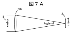
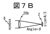
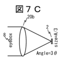
- FIGS. 7A, 7B, and 7C are explanatory diagrams showing the relationship between the miniaturization of the image display element 2 and the projection optical system 20b.
- the projection optical system 20b includes at least the mirror 5 and the windshield 6.
- FIG. 7A is a diagram showing an image display element 2 of a reference size.
- the size of the reference image display element 2 is designated as A.
- FIG. 7B is a diagram showing an example of a small image display element 2.
- FIG. 7B is a diagram of FIG. 7A miniaturized by being transformed to 1/3 the size, with the size of the image display element 2 being A/3. With the configuration of FIG. 7B, the size of the eye box 8 is also small, so it is not possible to ensure the size of the eye box 8 required for the head-up display device 30.
- FIG. 7C is a diagram showing another example of a small image display element 2.
- Fig. 7C like Fig. 7B, the size of the image display element 2 is A/3, but the size of the eye box 8 is returned to the same size as in Fig. 7A.
- the LCD panel is made smaller, the optical performance of the projection optical system will be significantly degraded, or a larger number of lenses will be required to ensure the optical performance, resulting in a problem of larger size. Furthermore, if only the image display element 2 is made smaller, the virtual image will also become smaller, narrowing the viewing angle of the head-up display device.
- the present invention was made in consideration of the above-mentioned circumstances, and aims to provide a small head-up display device.
- one representative head-up display device of the present invention includes a display panel, a light source that supplies light to the display panel, a relay optical system that maps the image light emitted from the display panel, and a diffusion element that diffuses the image light mapped by the relay optical system, and the diffusion element has different optical effects in the horizontal and vertical directions of the diffusion element that correspond to the horizontal and vertical directions of the viewer.
- the present invention provides a small head-up display device. Problems, configurations, and advantages other than those described above will become clear from the description of the following embodiment.
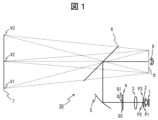
- FIG. 1 is a schematic configuration diagram of a head-up display device.
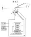
- 1 is a schematic configuration and functional block diagram of a head-up display device.
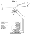
- 1 is a schematic configuration and functional block diagram of a head-up display device.
- FIG. 1 is a plan view of a vehicle, which is a moving object equipped with a head-up display device, as viewed from the front.
- FIG. 13 is a diagram showing a configuration using a display panel of a standard size.
- FIG. 1 is a diagram showing a configuration using a display panel, a relay optical system, and a screen plate.
- FIG. 13 is a diagram showing a configuration using a display panel, a relay optical system, and a diffusion element unit.
- FIG. 1 is a schematic configuration diagram of a head-up display device.
- 1 is a schematic configuration and functional block diagram of a head-up display device.
- FIG. 1 is a plan view of a vehicle, which is a moving object equipped with a head-up
- FIG. 4 is a diagram showing an example of a configuration of a diffusion element portion.
- 13 is a diagram showing another example of the configuration of the diffusion element portion.
- FIG. 13 is a diagram showing another example of the configuration of the diffusion element portion.
- FIG. 13 is a diagram showing the diffusion of image light when no microlenses are used.
- FIG. 13 is a diagram showing an example of diffusion of image light when a microlens is used.
- 13A and 13B are diagrams illustrating another example of diffusion of image light when a microlens is used.
- 13A and 13B are diagrams illustrating another example of diffusion of image light when a microlens is used.
- 1A to 1C are diagrams illustrating an example of a projection optical system depending on the size of a display panel.
- FIG. 1A to 1C are diagrams illustrating an example of a projection optical system depending on the size of a display panel.
- 1A to 1C are diagrams illustrating an example of a projection optical system depending on the size of a display panel.
- FIG. 1 is a schematic configuration diagram of a head-up display device.
- 1 is a schematic configuration and functional block diagram of a head-up display device.
- 1 is a schematic configuration and functional block diagram of a head-up display device.
- 3A and 3B are diagrams illustrating the basic configuration and function of a diffusion element portion.
- FIG. 13 is a diagram showing mapping of incident light rays on a diffusion element portion.
- FIG. 13 is a diagram showing mapping of emitted light rays from a diffusion element portion.
- FIG. 11 is a diagram showing an example of lens data of a diffusion element portion.
- FIG. 13 is a diagram showing an example of free-form surface coefficients of a diffusion element portion.
- FIG. 13 is a diagram showing an example of diffusion of image light when a microlens is used.
- FIG. 13 is a diagram showing an example of diffusion of image light, with the same incident light as that shown in FIG. 1A and 1B are diagrams showing examples of ray diagrams in the YZ section and the XZ section of a free curved lens;
- FIG. 13 is a diagram showing another example of lens data of the diffusion element portion.
- FIG. 11 is a diagram showing another example of the free-form surface coefficients of the diffusion element portion.
- FIG. 13A and 13B are diagrams illustrating another example of diffusion of image light when a microlens is used.
- 13 is a diagram showing another example of diffusion of image light, with the same incident light as that of the image light without a microlens.
- FIG. 11A and 11B are diagrams showing another example of ray diagrams in the YZ section and the XZ section of the free curved lens.
- the basic configuration of the head-up display device 30 will be described using FIG. 1.
- the head-up display device may also be called a display device, a virtual image display device, etc.
- the head-up display device 30 shown in FIG. 1 includes an image forming unit and an image projection unit.
- the image forming unit includes a light source 1 and an image display element or display panel 2.
- the image projection unit may include a mirror 5.
- the light source 1 emits light to the image display element or display panel 2, and then the image light from the display panel 2 is incident on the mirror 5, and the image light emitted from the mirror 5 is reflected by the windshield 6 of a vehicle (for example, the automobile 500 in FIG. 3) and incident on the observer's eye 9.
- the projection of the image light onto the windshield 6 of the vehicle is described, but the projection unit that projects the image light may be a projection member such as a combiner.
- the projection unit that projects the image light may be a projection member such as a combiner.
- the mirror 5 functions as an image projection unit that magnifies and reflects the image light from the image display element or display panel 2 in a direction at a set angle or in a specified direction.
- the mirror 5 is, for example, a concave mirror (magnifying mirror) and is provided on the optical path between the image display element or display panel 2 and the windshield 6.
- the mirror 5 functions as an image light projection unit that projects the image light emitted from the display panel 2 onto the windshield 6, thereby causing the projected image light to be visually recognized as a virtual image by the eye 9 of a user such as a driver.
- the mirror 5 in this embodiment is composed of a mirror having a concave reflective surface.
- the head-up display device includes a display panel 2, a light source 1, and a controller 200 that controls the operations of these components.
- the head-up display device further includes a relay optical system 3 and a diffusion element unit 4. Light is irradiated from the light source 1 to the display panel 2, and image information (video information) displayed on the display panel 2 is emitted toward the mirror 5 via the relay optical system 3 and the diffusion element unit 4.
- the combination of the light source 1, the display panel 2, the relay optical system 3, and the diffusion element unit 4 may be referred to as an optical system.
- the light source 1 is typically configured to include an LED (Light Emitting Diode) light source, and multiple light sources may be arranged for use.
- the image display element or display panel 2 is typically a liquid crystal panel (Liquid Crystal Display: LCD).
- the display panel 2 creates an image based on image data input instructed by the controller 200, and displays it on the display surface of the display element of the display panel 2.
- the image display element 2 may be referred to as a liquid crystal display panel, liquid crystal display element, display element, display panel, etc.
- the light source 1 may also be referred to as a backlight.
- the head-up display device 30 is a device equipped with a controller 200. Also, as shown in FIG. 2B, if the controller 200 is not provided, it is possible for the control unit of the automobile to function as the controller 200. When controlled by the control unit of the automobile, the control is almost the same as that of the controller 200 of the head-up display device 30, and the following embodiment will be described using the controller 200 of the head-up display device 30. In other words, the head-up display device 30 may be equipped with the controller 200, or an external control device such as an automobile may be used.
- a navigation system 208 which is a navigation device that generates and outputs information related to the operation of the mobile object equipped with the head-up display device 30, and an ECU (Electronic Control Unit) 209 that controls the operation of the mobile object are connected to the controller 200.
- Various sensors 210 equipped on the mobile object are connected to the ECU 209, and the ECU 209 is configured to notify the ECU 209 of the detected information.
- the controller 200 includes a microcomputer 202 that processes various data from the external devices described above, a storage device 206 connected to the microcomputer 202, and a backlight drive circuit 207 for driving the backlight 1.
- the microcomputer 202 is equipped with a RAM (Random Access Memory) 203 for storing various data from external devices, a CPU (Central Processing Unit) 205 for performing calculations to generate image data that is the basis of the virtual image viewed by the observer, and a ROM (Read Only Memory) 204 for storing programs and parameters that can execute the calculations in the CPU 205.
- a RAM Random Access Memory
- CPU Central Processing Unit
- ROM Read Only Memory
- the controller 200 having the above configuration displays image information on the image display element 2.
- the image information displayed on the image display element 2 is emitted as image light by the light emitted by the backlight 1 through the relay optical system 3 and the diffusion element section 4 towards the mirror 5.
- the image light emitted from the display panel 2 is projected onto the windshield 6 by the mirror 5.
- the image light projected from the mirror 5 onto the windshield 6 is reflected by the windshield 6 and reaches the position of the observer's eye 9. This creates a relationship as if the observer's eye 9 were looking at the image information on the virtual image surface 7. Note that if the mirror 5 is not provided, the image light from the display panel 2 is emitted onto the windshield 6, and the image light emitted onto the windshield 6 is reflected by the windshield 6 and reaches the position of the observer's eye 9.
- the eyebox 8 is the range in which points V1, V2, and V3 on the virtual image plane 7 can be seen even if the observer moves the position of the eye 9.
- the relay optical system 3, the diffusion element section 4, and the mirror 5 may be called a projection optical system that displays an image (virtual image) of an object (spatial image) in front of the observer's eye 9. Note that the projection optical system does not have to include the mirror 5.
- FIG. 3 is a plan view of an automobile 500, which is a moving body equipped with a head-up display device 30, as seen from the front.
- a windshield 6 which is a front glass used as a windshield, is disposed in front of the driver's seat.
- the head-up display device 30 projects image light onto the windshield 6, allowing the driver and observers in the vehicle 500 to view various information related to the vehicle 500 as virtual images.
- the image light is projected onto the front of the driver's seat or its surroundings. For example, the image light is projected onto the position shown in the dashed rectangular area R1.
- the projection optical system 20b includes a mirror 5 ( Figure 2A).
- the mirror 5 is a concave mirror, and has a light-collecting effect, so it has the same effect as a convex lens.
- the projection optical system 20b is not a convex lens, and the optical components may include a concave lens in addition to the mirror 5.
- Fig. 4A is a diagram showing a configuration using an image display element 2 of a standard size.
- the size of the standard image display element 2 is designated as A.
- Fig. 4B is a diagram showing a configuration using a small image display element 2, relay optical system 3, and screen plate 4b.
- the size of the image display element 2 is A/3.
- a relay optical system 3 with a magnification of 3x is used to map onto the screen plate 4b, ensuring the size of the eyebox 8.
- the angle of the relay optical system 3 on the screen plate 4b side is ⁇
- the angle of the relay optical system 3 on the image display element 2 side is 3 ⁇
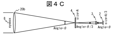
- Fig. 4C is a diagram showing a configuration using a small image display element 2, relay optical system 3, and diffusion element section 4.
- the size of the image display element 2 is A/3, but the angle of the relay optical system 3 on the image display element 2 side remains ⁇ , and the angle of the relay optical system 3 on the diffusion element section 4 side is set to ⁇ /3, and the diffusion element section 4 diffuses the image light, ensuring the size of the eye box 8.
- the angle ⁇ in Fig. 4C is made up of the light entering the upper part of the relay optical system 3 from the image display element 2 and the light entering the lower part of the relay optical system 3.
- Fig. 4C makes it possible to use a small image display element 2 without enlarging the relay optical system 3. Details of this diffusion element section 4 will be described with reference to Figs. 5A to 5C.
- the X-axis is the horizontal direction, left-right direction, lateral direction or width direction of the vehicle
- the Y-axis is the up-down direction, vertical direction or length direction of the vehicle
- the Z-axis which is perpendicular to the lateral direction of the vehicle, is the front-rear direction of the vehicle or the traveling direction of the vehicle.
- the X-axis and Y-axis correspond to the horizontal and vertical directions of the field of view (eye box 8) that the observer can observe.
- the observation range is larger by the distance between the left and right eyes.
- the eye box 8 is 130 mm horizontally and 50 mm vertically. Therefore, the side of the diffusion element 4 that corresponds to the X-axis direction requires a larger observation range than the side that corresponds to the Y-axis direction.
- the radius of curvature of the cylinder lens can only be seen from a specific direction, for example, when the light incident side of the microlens array 41 is viewed from the left or right, and the light exit side of the microlens array 41 is viewed from above or below.
- the light incident side of the microlens array 41 is flat, and the light exit side of the microlens array 41 diffuses light in the vertical and horizontal directions.
- the light incident side of the microlens array 41 diffuses light in the Y-axis direction (vertical direction), and the light exit side of the microlens array 41 diffuses light in the X-axis direction (horizontal direction).
- the light incident side of the microlens array 41 is flat, and the light exit side of the microlens array 41 diffuses light in the horizontal direction.
- the diffusion element section 4 includes a microlens array 41 and a light-shielding grating 42a.
- the light-shielding grating and the microlens array are arranged via an adhesive or a holding section.
- the microlens array 41 has one or more microlenses.
- the light-shielding grating 42a has one or more openings and is arranged on the light-emitting side of the microlens array 41.
- the microlens array 41 also corresponds to the openings of the light-shielding grating 42a.
- One microlens may correspond to one opening, or one or more microlenses may correspond to one opening, and there is no particular limitation.
- the light-shielding grating has an opening, the opening has one or more openings, and the opening corresponds to at least one microlens.
- the openings of the light-shielding grating for performing the shielding action are arranged according to the microlens array.
- Each pixel of the image display element 2 corresponds to each cell of the microlens array 41 mapped by the relay optical system 3.
- the light incident side of the microlens array 41 is flat, and the light exit side of the microlens array 41 diffuses light in both the vertical and horizontal directions.
- the microlens array 41 has different radii of curvature in the XZ cross section and the YZ cross section, and the diffusion angle in the X-axis direction is greater than the diffusion angle in the Y-axis direction.
- the divergence effect of each microlens of the microlens array 41 in the horizontal direction (X-axis direction) is greater than the divergence effect of each microlens of the microlens array 41 in the vertical direction (Y-axis direction).
- the "diffusion effect" in this invention may also be referred to as a "divergence effect”.
- a toroidal lens or a free-form lens can be used as the microlens.
- Each opening of the light-shielding grid 42a corresponds to each lens of the microlens array 41, and blocks light that spreads to the periphery of each cell in the focused image (spot) of light in each cell of the microlens array 41 mapped by the relay optical system 3.
- the aperture ratio of each pixel of the image display element 2 is about 50%, so degradation of resolution is prevented by blocking the light beam of the relay optical system 3 that spreads beyond the magnification.
- Fig. 5B(1) to Fig. 5B(4) are diagrams showing another example of the configuration of the diffusion element section 4.
- the light-shielding grating 42a is arranged on the light-emitting side of the microlens array 41, but in Fig. 5B, the light-shielding grating 42c is arranged on the light-incident side of the microlens array 41, and the light-shielding grating 42b is arranged on the light-emitting side of the microlens array 41.
- the light-shielding grating and the microlens array are arranged by bonding or via a structure, etc.
- the microlenses on the light incident side diffuse light in the Y-axis direction
- the microlenses on the light exit side diffuse light in the X-axis direction
- a light-shielding grating 42b is arranged in the X-axis direction
- a light-shielding grating 42c is arranged in the Y-axis direction.
- the light incident side of the microlens array 41 diffuses light in the vertical direction
- the light exit side of the microlens array 41 diffuses light in the horizontal direction.
- FIG. 5B shows a light-shielding grating arranged in the direction of diffusion
- the light-shielding grating 42a of FIG. 5A may also be used.
- FIGS. 5C(1) to 5C(3) are diagrams showing another example of the configuration of the diffusion element section 4.
- the microlens array 41 in FIG. 5C has a shape with a radius of curvature only in the X-axis direction, and for example, a cylindrical lens array or a free-form lens array can be used.
- the incident side of the microlens array 41 is flat, and the exit side of the microlens array 41 diffuses light in the horizontal direction.
- the microlens array 41 in FIG. 5C has a diffusing effect only in the X-axis direction.
- each microlens of the microlens array 41 has a diverging effect only in the horizontal direction (X-axis). Therefore, in FIG. 5C, a light-shielding grating 42b that has a shading effect only in the Y-axis direction is arranged on the light exit side.
- the light-shielding grating 42b in Fig. 5C may have a shape that has a shielding effect only in the Y-axis direction, or the light-shielding grating 42a in Fig. 5A may be used.
- the microlens array 41 shown in Figs. 5A to 5C may be configured to have different divergence effects on the light incident side and the light exit side.
- the diffusion element unit 4 may have a structure (holding) the microlens array 41 and the light-shielding gratings 42a, 42b, and 42c as an integral unit.
- Each microlens of the microlens array 41 may have a diffusion effect on at least one of the light entrance surface side and the light exit surface side of the diffusion element unit.
- a telecentric optical design may be performed, or a lenticular lens may be disposed immediately before the diffusion element unit 4.
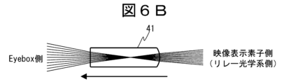
- Figures 6A to 6D show the state in which the image light is incident on the microlens array 41 from the relay optical system 3 side.
- FIG. 6A is a diagram showing the diffusion of image light when no microlenses are used.
- FIG. 6A shows the case where the microlens array 41 is not used as a reference, and the shape of the image light on the image display element side or relay optical system side is approximately the same as that on the Eyebox side.
- FIG. 6B is a diagram showing an example of the diffusion of image light when a microlens is used.
- a microlens array 41 with positive refractive power is placed in front of the focusing position of the relay optical system 3, thereby increasing the angle at which the image light is diffused.
- FIG. 6C is a diagram showing another example of diffusion of image light when microlenses are used.
- a microlens array 41 with positive refractive power is placed in front of the focusing position of the relay optical system 3 and with negative refractive power is placed behind the focusing position, thereby further increasing the angle at which the image light is diffused.
- FIG. 6D is a diagram showing another example of diffusion of image light when microlenses are used.
- a microlens array 41 with a decentered negative refractive power is placed after the focusing position of the relay optical system 3, thereby increasing the angle at which the image light is diffused and emitting the light at an angle.
- each microlens of the microlens array 41 may be a decentered lens.
- the head-up display device of this embodiment includes a light source 1, a display panel 2, a relay optical system 3 that maps the image light emitted from the display panel 2, and a diffusion element unit 4 that diffuses the image light mapped by the relay optical system 3.
- a mirror 5 that reflects the image light diffused by the diffusion element unit 4 may also be included. When the mirror 5 is included, the light reflected by the mirror 5 is projected onto a projection member such as a windshield 6 to display a virtual image. When the mirror 5 is not included, the image light diffused by the diffusion element unit 4 is output to a projection member such as a windshield 6 to display a virtual image.
- the diffusion element unit 4 includes a microlens array 41 having a plurality of microlenses, and the microlens array 41 has different optical effects in the horizontal and vertical directions of the microlens array 41, which correspond to the horizontal and vertical directions of the field of view in which the virtual image can be observed.
- the optical performance of the projection optical system 20b can be ensured without increasing the number of lenses, making it possible to provide a compact head-up display device.
- the image display element 2 may be a reflective image display element in addition to a transmissive liquid crystal display panel.
- a telecentric optical design may be used, or a lenticular lens may be placed immediately before the diffusion element section 4.
- the head-up display device 30 may be called a display device, a virtual image display device, or the like.
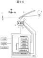
- the head-up display device 30 shown in FIG. 8 includes an image forming unit and an image projection unit.
- the image forming unit includes a light source 1 and an image display element or display panel 2.
- the image projection unit may include a concave lens 10 and a mirror 5.
- the light source 1 emits light to the image display element or display panel 2, and then the image light from the display panel 2 is incident on the mirror 5, and the image light emitted from the mirror 5 is reflected by the windshield 6 of a vehicle (for example, the automobile 500 in FIG. 3) and incident on the observer's eye 9.
- the projection of the image light onto the windshield 6 of the vehicle is described, but the projection unit that projects the image light may be a projection member such as a combiner.
- the projection unit that projects the image light may be a projection member such as a combiner.
- the mirror 5 functions as an image projection unit that magnifies and reflects the image light from the image display element or display panel 2 in a set angle direction or a specified direction.
- the mirror 5 is, for example, a concave mirror (magnifying mirror) and is provided on the optical path between the image display element or display panel 2 and the windshield 6.
- the mirror 5 functions as an image light projection unit that projects the image light emitted from the display panel 2 onto the windshield 6, thereby causing the projected image light to be visually recognized as a virtual image by the eye 9 of a user such as a driver.
- the mirror 5 in this embodiment is composed of a mirror having a concave reflective surface.
- the mirror 5 may also be called a reflective element, a reflective mirror, etc.
- the head-up display device includes a display panel 2, a light source 1, and a controller 200 that controls the operations of these components.
- the head-up display device further includes a relay optical system 3, a diffusion element section 4, and a concave lens 10.
- Light is irradiated from the light source 1 to the display panel 2, and image information (video information) displayed on the display panel 2 is emitted toward the mirror 5 via the relay optical system 3, the diffusion element section 4, and the concave lens 10.
- the combination of the light source 1, the display panel 2, the relay optical system 3, the diffusion element section 4, and the concave lens 10 may be referred to as an optical system.
- the light source 1 is typically configured to include an LED (Light Emitting Diode) light source, and multiple light sources may be arranged for use.
- the image display element or display panel 2 is typically a liquid crystal panel (Liquid Crystal Display: LCD).
- the display panel 2 creates an image based on image data input instructed by the controller 200, and displays it on the display surface of the display element of the display panel 2.
- the image display element 2 may be called a liquid crystal display panel, liquid crystal display element, display element, display panel, etc.
- the light source 1 may also be called a backlight.
- the concave lens 10 may also be called an optical element.
- the head-up display device 30 is a device equipped with a controller 200. Also, as shown in FIG. 9B, if the controller 200 is not provided, it is possible for the control unit of the automobile to function as the controller 200. When controlled by the control unit of the automobile, the control is almost the same as that of the controller 200 of the head-up display device 30, and the following embodiment will be described using the controller 200 of the head-up display device 30. In other words, the head-up display device 30 may be equipped with the controller 200, or an external control device such as an automobile may be used.
- a navigation system 208 which is a navigation device that generates and outputs information related to the operation of the mobile object equipped with the head-up display device 30, and an ECU (Electronic Control Unit) 209 that controls the operation of the mobile object are connected to the controller 200.
- Various sensors 210 equipped on the mobile object are connected to the ECU 209, and the ECU 209 is configured to notify the ECU 209 of the detected information.
- the controller 200 includes a microcomputer 202 that processes various data from the external devices described above, a storage device 206 connected to the microcomputer 202, and a backlight drive circuit 207 for driving the backlight 1.
- the microcomputer 202 is equipped with a RAM (Random Access Memory) 203 for storing various data from external devices, a CPU (Central Processing Unit) 205 for performing calculations to generate image data that is the basis of the virtual image viewed by the observer, and a ROM (Read Only Memory) 204 for storing programs and parameters that can execute the calculations in the CPU 205.
- a RAM Random Access Memory
- CPU Central Processing Unit
- ROM Read Only Memory
- the controller 200 having the above configuration displays image information on the image display element 2.
- the image information displayed on the image display element 2 is emitted as image light by the light irradiated by the backlight 1 through the relay optical system 3, the diffusion element section 4, and the concave lens 10 toward the mirror 5.
- the image light emitted from the display panel 2 is projected onto the windshield 6 by the mirror 5.
- the image light projected from the mirror 5 onto the windshield 6 is reflected by the windshield 6 and reaches the position of the observer's eye 9. This creates a relationship as if the observer's eye 9 were looking at the image information on the virtual image surface 7. Note that if the mirror 5 is not provided, the image light from the display panel 2 is emitted onto the windshield 6, and the image light emitted onto the windshield 6 is reflected by the windshield 6 and reaches the position of the observer's eye 9.
- the eyebox 8 is the range in which points V1, V2, and V3 on the virtual image plane 7 can be seen even if the observer moves the position of the eye 9.
- the relay optical system 3, the diffusion element section 4, the concave lens 10, and the mirror 5 may be called a projection optical system that displays an image (virtual image) of an object (spatial image) in front of the observer's eye 9. Note that the projection optical system does not have to include the mirror 5.
- FIG. 3 is a plan view of an automobile 500, which is a moving body equipped with a head-up display device 30, as seen from the front.
- a windshield 6 which is a front glass used as a windshield, is disposed in front of the driver's seat.
- the head-up display device 30 projects image light onto the windshield 6, allowing the driver and observers in the vehicle 500 to view various information related to the vehicle 500 as virtual images.
- the image light is projected onto the front of the driver's seat or its surroundings. For example, the image light is projected onto the position shown in the dashed rectangular area R1.
- the projection optical system 20b includes a mirror 5 ( Figure 9A).
- the mirror 5 is a concave mirror, and has a light-collecting effect, so it has the same effect as a convex lens.
- the projection optical system 20b is not a convex lens, and the optical components may include a concave lens in addition to the mirror 5.
- Fig. 4A is a diagram showing a configuration using an image display element 2 of a standard size.
- the size of the standard image display element 2 is designated as A.
- Fig. 4B is a diagram showing a configuration using a small image display element 2, relay optical system 3, and screen plate 4b.
- the size of the image display element 2 is A/3.
- a relay optical system 3 with a magnification of 3x is used to map onto the screen plate 4b, ensuring the size of the eyebox 8.
- the angle of the relay optical system 3 on the screen plate 4b side is ⁇
- the angle of the relay optical system 3 on the image display element 2 side is 3 ⁇
- Fig. 4C is a diagram showing a configuration using a small image display element 2, relay optical system 3, and diffusion element section 4.
- the size of the image display element 2 is A/3, but the angle of the relay optical system 3 on the image display element 2 side remains ⁇ , and the angle of the relay optical system 3 on the diffusion element section 4 side is set to ⁇ /3, and the diffusion element section 4 diffuses the image light, ensuring the size of the eye box 8.
- the angle ⁇ in Fig. 4C is made up of the light entering the upper part of the relay optical system 3 from the image display element 2 and the light entering the lower part of the relay optical system 3.
- Fig. 4C makes it possible to use a small image display element 2 without enlarging the relay optical system 3. Details of this diffusion element section 4 will be described with reference to Figs. 10 to 17.
- the X-axis is the horizontal direction, left-right direction, lateral direction or width direction of the vehicle
- the Y-axis is the up-down direction, vertical direction or length direction of the vehicle
- the Z-axis which is perpendicular to the lateral direction of the vehicle, is the front-rear direction of the vehicle or the direction of travel of the vehicle.
- the X-axis and Y-axis correspond to the horizontal and vertical directions of the field of view (eye box 8) that the observer can observe.
- the observation range is larger by the distance between the left and right eyes.
- the eye box 8 is 130 mm horizontally and 50 mm vertically. Therefore, the side of the diffusion element 4 that corresponds to the X-axis direction requires a larger observation range than the side that corresponds to the Y-axis direction.
- the convex surface on the light incident side of the microlens array 41 and the concave surface on the light exit side of the microlens array 41 perform the diffusion effect.
- a light-shielding grating 42a is arranged on the light incident side of the microlens array 41, and a light-shielding grating 42b is arranged on the light exit side of the microlens array 41.
- Each cell of the microlens array 41 corresponds to each opening of the light-shielding grating 42a in FIG. 10(2).
- Each opening of the light-shielding grating 42a corresponds to each microlens of the microlens array 41, and blocks light that spreads to the periphery of each cell from the focused image (spot) of light in each cell of the microlens array 41 mapped by the relay optical system 3.
- the aperture ratio of each pixel of the image display element 2 is about 50%, so that the deterioration of the resolution is prevented by blocking the light beam of the relay optical system 3 that spreads more than the magnification.
- the light-shielding grating and the microlens array are arranged by bonding or via a structure.
- the diffusion element section 4 may have a structure (holding) the microlens array 41 and the light-shielding gratings 42a, 42b as an integrated unit.
- a telecentric optical design may be used between the relay optical system 3 and the diffusion element section 4, or a Fresnel lens may be placed just before the diffusion element section 4.
- the relay optical system 3 is also designed to be telecentric, so that light beams of the same conditions are incident on each microlens of the microlens array 41.
- FIG. 11A is a cross-sectional view of the incident light beams for each microlens of the microlens array 41 in FIG. 10(1), and shows a mapping in which A0 to A5 are assigned to representative points.
- FIG. 11B is a cross-sectional view of the exiting light beams for each microlens of the microlens array 41 in FIG. 10(1), and shows a mapping in which B0 to B5 are assigned to representative points. Since the circular shape is converted into a rectangular shape, it is symmetrical from left to right and from top to bottom, so in the cross-sectional view of FIG.
- point B3 is placed at the diagonal of the rectangular shape, and the line segment B0-B3 further divides the four divisions into two, resulting in eight divisions of the area of the original rectangular shape.
- point A3 on the cross section of the incident light beam corresponds to point B3 on the cross section of the outgoing light beam.
- point B2 is placed halfway between points B1 and B3 of the rectangular shape, and point B4 is placed halfway between points B3 and B5.
- the eight-division area is then further divided into two parts by line segments B0-B2 and B0-B4, resulting in a 16-division of the area of the original rectangular shape. This can also be understood from the fact that points B2 and B4 are the midpoints of the bases of the triangles divided into eight parts.
- the points A1 to A5 are evenly spaced around the outer periphery of the circular cross section of the incident light beam, and the light density around the outer periphery of the rectangular cross section of the exiting light beam is uniform, and points A0 to A5 in Figure 11A correspond in order to points B0 to B5 in Figure 11B.
- FIG. 11A the circular shape including points A1 to A5 is reduced by 50% to become the circular shape shown by the dotted line, which has a quarter of the area of the original circle.
- Fig. 11B the rectangular shape including points B1 to B5 is reduced by 50% to become the rectangular shape shown by the dotted line, which has a quarter of the area of the original rectangle. Therefore, a sequence of points similar to points A1 to A5 is placed on the dotted circular shape in Fig.
- FIG. 12A shows an example of a diffusion element 4 that converts an incident light beam with a circular cross section into an outgoing light beam with a rectangular cross section, and makes the light density closer to uniform.
- the microlens of the diffusion element 4 in Figure 12A is composed of a single free-form lens, and Figure 12B shows its free-form surface coefficients (Equation 1).
- the incident light beam that enters this single free-form lens and the converted outgoing light beam will be explained using Figures 13A and 13B.
- the size of the image plane is 3226 mm horizontal x 1001 mm vertical, which realizes the same ratio as the eye box 8 of 130 mm x 40 mm.
- the size of the image plane is 3226 mm horizontal x 1001 mm vertical, which realizes the same ratio as the eye box 8 of 130 mm x 40 mm.
- FIG. 12A in front of and behind the free-form lens is to simply show the distribution of the exit angle of the light beam on the image plane in the spot diagram by separating the image plane to a distance where the height of the light beam on the free-form lens can be ignored compared to the height of the light beam on the image plane. Therefore, optical elements are arranged immediately before and after the actual free-form lens (microlens array 41) (Fig. 8). In this embodiment, a convex Fresnel lens is arranged on the reduction side, and a concave lens 10 is arranged on the enlargement side.
- Figure 13B shows the same incident light beam as Figure 13A, but shows the emitted light beam without the microlens array 41, and is also the incident light beam itself. Therefore, in Figure 13A, it can be seen that the emitted light beam has a large emission angle in the horizontal direction, and has a rectangular cross section in the horizontal and vertical directions.
- Figure 14 is a ray diagram at the YZ cross section and XZ cross section of a free-form lens, where the light beam at the entrance surface is circular and the light beam at the exit surface is elongated.
- the size of the light beam at the entrance surface and exit surface of the free-form lens is less than twice as large because the cross-sectional area of the light beam at the YZ cross section and the XZ cross section is minimized between the entrance surface and exit surface of the microlens array 41 (free-form lens), preventing the free-form lens from becoming too large.
- the light beam at the exit surface of the free-form lens is aligned into a vertically elongated rectangular shape, and the free-form surface at the exit surface greatly expands the horizontal diffusion angle, thereby realizing a horizontally elongated rectangular shape on the image plane.
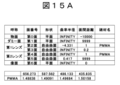
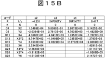
- FIG. 15A is composed of two free-form lenses, and Figure 15B shows the free-form surface coefficients (Equation 1).
- the incident light beam that enters these two free-form lenses and the converted outgoing light beam will be explained using Figures 16A and 16B.
- the size of the image plane is 3262 mm horizontal x 1010 mm vertical, which realizes the same ratio as the eye box 8 of 130 mm x 40 mm.
- the reason for leaving a gap of 10 m (Fig.
- FIG. 15A in front of and behind the free-form lens is to simply show the distribution of the exit angle of the light beam on the image plane in the spot diagram by separating the image plane to a distance where the height of the light beam at the free-form lens can be ignored compared to the height of the light beam on the image plane. Therefore, optical elements are arranged immediately before and after the actual free-form lens (microlens array 41) (Fig. 8). In this embodiment, a convex Fresnel lens is arranged on the reduction side, and a concave lens 10 is arranged on the enlargement side.
- Figure 16B shows the same incident light beam as Figure 16A, but shows the emitted light beam without the microlens array 41, and is also the incident light beam itself. Therefore, in Figure 16A, it can be seen that the emitted light beam has a large emission angle in the horizontal direction, and has a rectangular cross section in the horizontal and vertical directions.
- Figure 17 is a ray diagram at the YZ cross section and XZ cross section of a free-form lens, where the light beam at the entrance surface is circular and the light beam at the exit surface is elongated.
- the size of the light beam at the entrance surface and exit surface of the free-form lens is approximately the same because the cross-sectional area of the light beam at the YZ cross section and the XZ cross section between the entrance surface and exit surface of the microlens array 41 (free-form lens) is minimized, preventing the free-form lens from becoming too large.
- the light beam at the exit surface of the free-form lens is aligned into a vertically elongated shape, and the free-form surface at the exit surface greatly expands the horizontal diffusion angle, thereby achieving a horizontally elongated rectangular shape on the image plane.
- the microlens array 41 has a different radius of curvature in the XZ cross section and in the YZ cross section, and the diffusion angle in the X-axis direction is greater than the diffusion angle in the Y-axis direction.
- the divergence effect of each microlens of the microlens array 41 in the horizontal direction (X-axis direction) is greater than the divergence effect of each microlens of the microlens array 41 in the vertical direction (Y-axis direction).
- the "diffusion effect" in this invention may also be referred to as a "divergence effect.”
- the head-up display device of this embodiment includes a light source 1, a display panel 2, a relay optical system 3 that maps the image light emitted from the display panel 2, a diffusion element unit 4 that diffuses the image light mapped by the relay optical system 3, and a concave lens 10.
- a mirror 5 that reflects the light diffused by the diffusion element unit 4 and passing through the concave lens 10 may also be included.
- the mirror 5 the light reflected by the mirror 5 is projected onto a projection member such as a windshield 6 to display a virtual image.
- the mirror 5 is not included, the light emitted from the concave lens 10 is emitted onto a projection member such as a windshield 6 to display a virtual image.
- the diffusion element unit 4 includes a microlens array 41 having a plurality of microlenses, and the microlens array 41 has different optical effects in the horizontal and vertical directions of the microlens array 41, which correspond to the horizontal and vertical directions of the visual field range in which the virtual image can be observed.
- the optical performance of the projection optical system 20b can be ensured without increasing the number of lenses, making it possible to provide a compact head-up display device.
- the image display element 2 may be a reflective image display element in addition to a transmissive liquid crystal display panel.
- the optical design between the relay optical system 3 and the diffusion element section 4 can be telecentric, or a Fresnel lens can be placed immediately before the diffusion element section 4.
- the technology according to this embodiment can display navigation information such as destination and speed, as well as information necessary for driving such as alert information when an oncoming vehicle or pedestrian is detected, in line with the actual view through the windshield.
- This can prevent traffic accidents by providing an information display device (head-up display device) that reduces the driver's viewpoint movement and contributes to supporting safe driving. This contributes to "Good health and well-being for all," one of the Sustainable Development Goals (SDGs) advocated by the United Nations.
- SDGs Sustainable Development Goals
Landscapes
- Physics & Mathematics (AREA)
- Engineering & Computer Science (AREA)
- General Physics & Mathematics (AREA)
- Optics & Photonics (AREA)
- Chemical & Material Sciences (AREA)
- Combustion & Propulsion (AREA)
- Transportation (AREA)
- Mechanical Engineering (AREA)
- Instrument Panels (AREA)
Abstract
L'objectif de la présente invention est de fournir un dispositif d'affichage tête haute compact. Un dispositif d'affichage tête haute (30) selon la présente invention comprend un écran d'affichage (2), une source de lumière (1) qui fournit de la lumière à l'écran d'affichage (2), un système optique de relais (3) qui mappe la lumière d'image émise par l'écran d'affichage (2), et une partie d'élément de diffusion (4) qui diffuse la lumière d'image mappée par le système optique de relais (3). La partie d'élément de diffusion (4) a différentes actions optiques dans la direction horizontale et la direction verticale de la partie d'élément de diffusion (4) qui correspondent à la direction horizontale et à la direction verticale d'un observateur.
Priority Applications (1)
| Application Number | Priority Date | Filing Date | Title |
|---|---|---|---|
| JP2025527596A JPWO2024257559A1 (fr) | 2023-06-16 | 2024-05-20 |
Applications Claiming Priority (4)
| Application Number | Priority Date | Filing Date | Title |
|---|---|---|---|
| JP2023-099673 | 2023-06-16 | ||
| JP2023099673 | 2023-06-16 | ||
| JP2023-140426 | 2023-08-30 | ||
| JP2023140426 | 2023-08-30 |
Publications (1)
| Publication Number | Publication Date |
|---|---|
| WO2024257559A1 true WO2024257559A1 (fr) | 2024-12-19 |
Family
ID=93851814
Family Applications (1)
| Application Number | Title | Priority Date | Filing Date |
|---|---|---|---|
| PCT/JP2024/018554 Ceased WO2024257559A1 (fr) | 2023-06-16 | 2024-05-20 | Système optique et dispositif d'affichage tête haute |
Country Status (2)
| Country | Link |
|---|---|
| JP (1) | JPWO2024257559A1 (fr) |
| WO (1) | WO2024257559A1 (fr) |
Citations (3)
| Publication number | Priority date | Publication date | Assignee | Title |
|---|---|---|---|---|
| JP2015146011A (ja) * | 2014-01-06 | 2015-08-13 | 株式会社Jvcケンウッド | 透過型スクリーン及びそれを用いた画像表示装置 |
| WO2018020678A1 (fr) * | 2016-07-29 | 2018-02-01 | マクセル株式会社 | Système optique de projection et dispositif d'affichage tête haute |
| US20200264431A1 (en) * | 2017-08-22 | 2020-08-20 | Continental Automotive Gmbh | Head-up display |
-
2024
- 2024-05-20 JP JP2025527596A patent/JPWO2024257559A1/ja active Pending
- 2024-05-20 WO PCT/JP2024/018554 patent/WO2024257559A1/fr not_active Ceased
Patent Citations (3)
| Publication number | Priority date | Publication date | Assignee | Title |
|---|---|---|---|---|
| JP2015146011A (ja) * | 2014-01-06 | 2015-08-13 | 株式会社Jvcケンウッド | 透過型スクリーン及びそれを用いた画像表示装置 |
| WO2018020678A1 (fr) * | 2016-07-29 | 2018-02-01 | マクセル株式会社 | Système optique de projection et dispositif d'affichage tête haute |
| US20200264431A1 (en) * | 2017-08-22 | 2020-08-20 | Continental Automotive Gmbh | Head-up display |
Also Published As
| Publication number | Publication date |
|---|---|
| JPWO2024257559A1 (fr) | 2024-12-19 |
Similar Documents
| Publication | Publication Date | Title |
|---|---|---|
| JP7217231B2 (ja) | 投影光学系及びヘッドアップディスプレイ装置 | |
| US10705333B2 (en) | Projection optical system and head-up display apparatus using the same | |
| US11119315B2 (en) | Information display apparatus | |
| US10788665B2 (en) | Projection optical system and head-up display device | |
| EP3447561B1 (fr) | Dispositif d'affichage tête haute | |
| JP6749334B2 (ja) | 投影光学系及びヘッドアップディスプレイ装置 | |
| JP7715889B2 (ja) | ヘッドアップディスプレイ | |
| JP6808745B2 (ja) | 投影光学系、及びヘッドアップディスプレイ装置 | |
| CN118778263A (zh) | 车辆用信息显示系统 | |
| JP6579180B2 (ja) | 虚像表示装置 | |
| US11561396B2 (en) | Head-up display device and transportation device | |
| JP2022189851A (ja) | 結像光学系および結像光学系を搭載した移動体 | |
| JP2025016748A (ja) | 空間浮遊映像表示装置 | |
| WO2017061016A1 (fr) | Dispositif d'affichage d'informations | |
| US20180252915A1 (en) | Head-up display device with narrow angle diffusion sheet | |
| JP6740360B2 (ja) | 投影光学系及びヘッドアップディスプレイ装置 | |
| WO2024257559A1 (fr) | Système optique et dispositif d'affichage tête haute | |
| US10852539B2 (en) | Projection optical system, head-up display device, and vehicle | |
| EP3534202B1 (fr) | Dispositif d'affichage d'image virtuelle | |
| JP7278447B2 (ja) | 車両 | |
| JP4372269B2 (ja) | 拡大表示装置 | |
| JP2020149063A (ja) | ヘッドアップディスプレイ装置 | |
| JP2020042287A (ja) | ヘッドアップディスプレイ装置 | |
| JP6593494B1 (ja) | 虚像表示装置 | |
| FUJITA et al. | Development of an automotive head-up display using a free-form mirror based optical system |
Legal Events
| Date | Code | Title | Description |
|---|---|---|---|
| 121 | Ep: the epo has been informed by wipo that ep was designated in this application |
Ref document number: 24823181 Country of ref document: EP Kind code of ref document: A1 |
|
| ENP | Entry into the national phase |
Ref document number: 2025527596 Country of ref document: JP Kind code of ref document: A |
|
| WWE | Wipo information: entry into national phase |
Ref document number: 2025527596 Country of ref document: JP |
|
| NENP | Non-entry into the national phase |
Ref country code: DE |