WO2024257562A1 - Blower and moving body - Google Patents
Blower and moving body Download PDFInfo
- Publication number
- WO2024257562A1 WO2024257562A1 PCT/JP2024/018689 JP2024018689W WO2024257562A1 WO 2024257562 A1 WO2024257562 A1 WO 2024257562A1 JP 2024018689 W JP2024018689 W JP 2024018689W WO 2024257562 A1 WO2024257562 A1 WO 2024257562A1
- Authority
- WO
- WIPO (PCT)
- Prior art keywords
- blower
- case body
- individual
- recess
- exhaust passage
- Prior art date
- Legal status (The legal status is an assumption and is not a legal conclusion. Google has not performed a legal analysis and makes no representation as to the accuracy of the status listed.)
- Ceased
Links
Images


Classifications
-
- B—PERFORMING OPERATIONS; TRANSPORTING
- B60—VEHICLES IN GENERAL
- B60K—ARRANGEMENT OR MOUNTING OF PROPULSION UNITS OR OF TRANSMISSIONS IN VEHICLES; ARRANGEMENT OR MOUNTING OF PLURAL DIVERSE PRIME-MOVERS IN VEHICLES; AUXILIARY DRIVES FOR VEHICLES; INSTRUMENTATION OR DASHBOARDS FOR VEHICLES; ARRANGEMENTS IN CONNECTION WITH COOLING, AIR INTAKE, GAS EXHAUST OR FUEL SUPPLY OF PROPULSION UNITS IN VEHICLES
- B60K11/00—Arrangement in connection with cooling of propulsion units
- B60K11/06—Arrangement in connection with cooling of propulsion units with air cooling
-
- F—MECHANICAL ENGINEERING; LIGHTING; HEATING; WEAPONS; BLASTING
- F04—POSITIVE - DISPLACEMENT MACHINES FOR LIQUIDS; PUMPS FOR LIQUIDS OR ELASTIC FLUIDS
- F04D—NON-POSITIVE-DISPLACEMENT PUMPS
- F04D29/00—Details, component parts, or accessories
- F04D29/40—Casings; Connections of working fluid
- F04D29/42—Casings; Connections of working fluid for radial or helico-centrifugal pumps
- F04D29/44—Fluid-guiding means, e.g. diffusers
-
- F—MECHANICAL ENGINEERING; LIGHTING; HEATING; WEAPONS; BLASTING
- F04—POSITIVE - DISPLACEMENT MACHINES FOR LIQUIDS; PUMPS FOR LIQUIDS OR ELASTIC FLUIDS
- F04D—NON-POSITIVE-DISPLACEMENT PUMPS
- F04D29/00—Details, component parts, or accessories
- F04D29/60—Mounting; Assembling; Disassembling
- F04D29/62—Mounting; Assembling; Disassembling of radial or helico-centrifugal pumps
Definitions
- This disclosure relates to a blower and a moving body.
- Patent Document 1 discloses a blower unit (air blower) having a fan housing (fan case) and a motor and blower fan (centrifugal fan) housed within the fan housing.
- the blower unit discharges airflow generated by the centrifugal fan through an outlet provided in the peripheral wall of the fan housing.
- the air intake of the blower is connected to the duct.
- An annular seal sponge is placed between the blower case body and the duct to prevent air from the outside from flowing into the blower.
- the seal sponge is attached to an annular attachment part on the case body.
- the cross-sectional area of the gas flow path is designed to gradually expand from the upstream to the downstream. Accordingly, the thickness of the case body at the annular attachment part also gradually decreases. As a result, when the resin that composes the case body is cooled and hardened after molding, the difference in shrinkage of the parts with different thicknesses causes the case body to warp (deform), and the flatness of the attachment part may not be maintained.
- the objective of this disclosure is to provide a blower and a moving body that have a high degree of flatness in the mounting portion of the case body where the sealing member is attached.
- a blower includes a case body that constitutes a circular passage and a part of an exhaust passage.
- the case body has an annular mounting portion on the outer surface of the case body, the mounting portion having a mounting surface to which a seal member is attached.
- the mounting portion has a first location on a side farther from the exhaust passage than the circumferential center point of the circular passage in the direction in which the circular passage extends, and a second location on a side closer to the exhaust passage than the circumferential center point of the circular passage.
- the first thickness of the case body at the first location is equal to or greater than the second thickness of the case body at the second location.
- a moving body includes the blower, an object to be cooled by the blower, and a moving body on which the blower and the object to be cooled are mounted.
- This disclosure provides a blower and a moving body with a highly flat mounting surface of the case body to which the sealing member is attached.
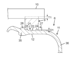
- FIG. 1 is a perspective view of a blower according to a first embodiment of the present disclosure.
- FIG. 2 is a schematic cross-sectional view of the blower.
- FIG. 3 is a plan view of the second case of the fan case of the blower.
- FIG. 4 is a perspective view of the second case.
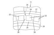
- FIG. 5 is a partially enlarged view of FIG. 3, showing a part of the attachment surface of the second case.
- FIG. 6 is a cross-sectional view showing a first state of the configuration in which the seal sponge is attached to the attachment surface of the same.
- FIG. 7 is a cross-sectional view showing a second state of the configuration in which the seal sponge is attached to the attachment surface of the same.
- FIG. 8 is a cross-sectional view of the first recess of the attachment surface of the same.
- FIG. 9 is a cross-sectional view of the second recess of the attachment surface of the same.
- FIG. 10 is a cross-sectional view of the third recess of the attachment surface of the same.
- FIG. 11 is a cross-sectional view of the fourth recess of the attachment surface of the same.
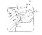
- FIG. 12 is a partial plan view of an inner surface of a second cover in the second embodiment of the present disclosure.
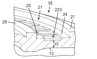
- FIG. 13 is a plan view of the second case of the fan case of the blower according to the third embodiment of the present disclosure.
- FIG. 14 is a cross-sectional view of the fifth recess of the attachment surface of the second case.
- FIG. 15 is a cross-sectional view of the sixth recess of the attachment surface of the same.
- FIG. 16 is a cross-sectional view of the seventh recess on the attachment surface of the same.
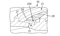
- FIG. 17 is a partial plan view of an inner surface of a second cover in the fourth embodiment of the present disclosure.
- FIG. 18 is a schematic diagram of a vehicle according to a fifth embodiment of the present disclosure.
- Fig. 1 is a perspective view of a blower 1 according to a first embodiment of the present disclosure.
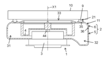
- Fig. 2 is a schematic cross-sectional view of the blower 1.
- the blower 1 is, for example, a blower for cooling a battery in a vehicle.
- the blower 1 is a centrifugal fan blower.
- the blower 1 mainly has a fan case 2, a motor 3, and a centrifugal fan 4.
- the motor 3 and the centrifugal fan 4 are housed inside the fan case 2.
- the fan case 2 has an intake port 33 for drawing in outside air, an exhaust port 34 for discharging air toward the outside space, and a circular passage 31 and an exhaust passage 32 which are passages connecting the intake port 33 and the exhaust port 34.
- the intake port 33 is circular.
- the exhaust port 34 is rectangular. Air is drawn into the fan case 2 from the intake port 33, flows through the circular passage 31 and the exhaust passage 32 in that order, and is discharged from the exhaust port 34.
- the motor 3 is, for example, an inner rotor type brushless motor.
- the motor 3 is not limited to a brushless motor.
- the motor 3 may be another type of DC motor or AC motor.
- a brushed motor may also be used as the motor 3.
- the direction in which the axis X1 (see FIG. 2) of the rotating shaft 44 of the motor 3 extends is defined as the axial direction.
- the direction extending from the axis X1 is defined as the radial direction, and the direction going around the axis X1 is defined as the circumferential direction.
- the centrifugal fan 4 is a member in which a plurality of blade members are connected at a predetermined interval between mutually opposing annular members.
- the centrifugal fan 4 is connected to the rotating shaft 44 of the motor 3 so as to rotate integrally therewith.
- the blade members can be formed of either metal or resin.
- the centrifugal fan 4 rotates at a predetermined speed in the circumferential direction in response to the rotation of the motor 3, thereby drawing in outside air from the intake port 33 and compressing it.
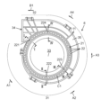
- FIG. 3 is a plan view of the second case 6 of the fan case 2 of the blower 1 according to the first embodiment of the present disclosure.
- the compressed air moves through the circulating passage 31 in the order of arrows A1, A2, A3, and A4 in FIG. 3.
- the compressed air further moves through the exhaust passage 32 in the direction of arrow B1 in FIG. 3.
- the compressed air is finally discharged from the exhaust port 34.
- the discharged air is supplied to the battery from the exhaust port 34.
- the fan case 2 is a hollow member formed by molding resin.
- the fan case 2 has an air intake port 33 on the top surface.
- the fan case 2 houses the motor 3 and the centrifugal fan 4, and is substantially cylindrical in shape.
- the fan case 2 has an upper wall, a side wall, and a lower wall of the circulating passage 31 and the exhaust passage 32.
- the fan case 2 is configured to cover the centrifugal fan 4. Due to this configuration, the circulating passage 31 and the exhaust passage 32 are formed inside the fan case 2 so as to follow the outer periphery of the centrifugal fan 4.
- the circulating passage 31 has a spiral shape so as to surround the outer periphery of the centrifugal fan 4.
- the exhaust passage 32 is linear.
- the circulating passage 31 is an internal space for guiding air sucked in from the intake port 33 to the exhaust passage 32 when the centrifugal fan 4 rotates due to the rotational motion transmitted from the motor 3.
- the area of a cross section including the axis X1 in the circulating passage 31 gradually increases toward the exhaust passage 32.
- the air intake 33 is, for example, an intake port for air into the vehicle cabin.
- the air intake 33 is formed on the axial end face (the end face at the top of the figure) of the substantially cylindrical fan case 2 that faces the vehicle cabin.
- the air intake 33 is an opening with a diameter that is approximately the same as or slightly smaller than that of the centrifugal fan 4.
- the air intake 33 is connected to the vehicle cabin via the duct 10 (see Figure 2).
- the duct 10 is a member for effectively directing air to the blower 1.
- the exhaust port 34 opens in a direction that is in a twisted relationship with the axial direction. In other words, air that is sucked in from a direction along the axis X1 of the centrifugal fan 4 toward the fan case 2 is exhausted in a direction that is in a twisted relationship with the axis X1.
- the fan case 2 is made of a resin such as polypropylene. As shown in Figures 1 and 2, the fan case 2 is divided into a lower first case 5 and an upper second case 6.
- the outer side of the first case 5 has a plurality of protrusions 41 spaced at predetermined intervals in the circumferential direction.
- the side of the second case 6 has a plurality of hooks 42 spaced at predetermined intervals in the circumferential direction.
- the first case 5 and second case 6 are connected by the plurality of hooks 42 engaging with the plurality of protrusions 41, respectively.
- the intake port 33 is formed in the second case 6.
- the exhaust port 34 is formed by fitting the second case 6 and the first case 5 together.
- the motor 3 and centrifugal fan 4 are fixed to the first case 5.
- the second case 6 has a case body 11.
- the case body 11 is a member that constitutes the upper part of the circulating passage 31 and the exhaust passage 32.
- the second case 6 mainly has an annular flat surface portion 35 and a side surface portion 36.
- the annular flat surface portion 35 is a roughly flat annular portion that constitutes the intake port 33.
- the side surface portion 36 is a roughly cylindrical portion that extends axially from the outer periphery of the annular flat surface portion 35.
- FIG. 3 is a plan view of the second case 6 of the fan case 2 of the blower 1 according to the first embodiment of the present disclosure.
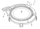
- Fig. 4 is a perspective view of the second case 6.
- an annular adhesive section 21 attachment section
- annular seal sponge 9 sealing member
- a plurality of individual recesses 22 are formed in the adhesive section 21 and are arranged at equal intervals in the direction in which the adhesive section 21 extends.
- Each individual recess 22 is generally rectangular in plan view.
- the attachment portion 21 further has, as an attachment surface, an outer peripheral plane 24 (first plane) on the outer peripheral side of the plurality of individual recesses 22, an inner peripheral plane 25 (second plane) on the inner peripheral side of the individual recesses 22, and a plurality of radial planes 26 extending between adjacent individual recesses 22 and connecting the outer peripheral plane 24 and the inner peripheral plane 25. Due to the above configuration and the plurality of individual recesses 22, the attachment portion 21 has a lattice shape in a plan view. An outer peripheral protrusion 27 extending in the axial direction is provided on the outer peripheral side of the outer peripheral plane 24. An inner peripheral protrusion 28 extending in the axial direction is provided on the inner peripheral side of the inner peripheral plane 25.
- the depth of the multiple individual recesses 22 gradually increases in the direction in which the circular passage 31 extends, from the side farther from the exhaust passage 32 to the side closer to the exhaust passage 32.
- the distance (shortest distance) between the bottom surface of each individual recess 22 and the inner surface 12 of the circular passage 31 is the same. This is because, as a prerequisite structure, the thickness of the part of the attachment portion 21 where the individual recesses 22 are not formed (for example, the distance between the outer peripheral plane 24 and the inner peripheral plane 25 and the inner surface 12 of the case body 11) decreases from the side farther from the exhaust passage 32 to the side closer to the exhaust passage 32.
- the distance (first distance, first thickness) between the bottom surface of the individual recess 22 (first location, first part) farther from the exhaust passage 32 than the circumferential center point C1 (FIG. 3) of the circular passage 31 and the inner side surface 12 of the circular passage 31 is the same as the distance (second distance, second thickness) between the bottom surface of the individual recess 22 (second location, second part) closer to the exhaust passage 32 than the circumferential center point C1 of the circular passage 31 and the inner side surface 12 of the circular passage 31.
- “same” means that the difference in thickness is only to the extent that no significant warping (deformation) occurs due to the difference in shrinkage between the parts with different thicknesses when the resin constituting the case body 11 is cooled and hardened after molding.
- the case where the thinnest part is 2 mm and the thickest part is 3 mm (1.5 times) is also included in “same”.
- the thickness of the thickest part is less than twice the thickness of the thinnest part.
- the former is in the range of 1.0 to 1.6 times the latter.
- each individual recess 22 may be flat, curved, or a combination of multiple surface shapes. It is preferable that the distance between the bottom surface of each individual recess 22 and the corresponding inner surface 12 is uniform across the entire bottom surface of each individual recess 22. For example, if the corresponding inner surface 12 is curved, it is preferable that the bottom surface of the individual recess 22 is curved to correspond to the inner surface 12.
- FIG. 6 is a cross-sectional view showing a first state of a configuration in which the seal sponge 9 is attached to the attachment surface of the second case 6 of the fan case 2 of the blower 1 according to the first embodiment of the present disclosure.
- Fig. 7 is a cross-sectional view showing a second state of a configuration in which the seal sponge 9 is attached to the attachment surface of the second case 6 of the fan case 2 of the blower 1 according to the first embodiment of the present disclosure.
- the seal sponge 9 is attached to the attachment portion 21. More specifically, the seal sponge 9 is attached to the outer peripheral flat surface 24, the inner peripheral flat surface 25, and the multiple radial flat surfaces 26 (see FIG. 5) between the outer peripheral protrusion 27 and the inner peripheral protrusion 28 via adhesive. In this state, a gap is secured between the seal sponge 9 and the bottom surface of the individual recess 22.
- the seal sponge 9 may be structured so as not to be in close contact with the bottom surface of the individual recess 22. In that case, it is preferable to set the ratio of the area of the individual recess 22 to the attachment portion 21 to an appropriate value. For example, the ratio of the area of the individual recess 22 to the attachment portion 21 is 40 to 60%.
- FIG. 8 is a cross-sectional view of the first recess 221 on the attachment surface of the second case 6 of the fan case 2 of the blower 1 according to the first embodiment of the present disclosure.
- FIG. 9 is a cross-sectional view of the second recess 222 on the attachment surface of the same.
- FIG. 10 is a cross-sectional view of the third recess 223 on the attachment surface of the same.
- FIG. 11 is a cross-sectional view of the fourth recess 224 on the attachment surface of the same.
- the first recess 221 and the second recess 222 in the following description are each an example of a first location on the side farther from the exhaust passage 32 than the circumferential center point C1 (see FIG. 3) of the circular passage 31.
- the third recess 223 and the fourth recess 224 are each an example of a second location on the side closer to the exhaust passage 32 than the circumferential center point C1 (see FIG. 3) of the circular passage 31.
- FIG. 8 is a cross-sectional view of the start point of the circular passage 31 in FIG. 3 or its surroundings (cross-sectional view taken along the line I-I in FIG. 3), showing the first recess 221.
- the inner peripheral portion of the first recess 221 has a curved surface shape that follows the curved surface shape of the inner surface 12.
- the inner peripheral portion of the first recess 221 has a thickness t11 (shortest distance between the bottom surface of the recess and the inner surface 12).
- the outer peripheral portion of the first recess 221 has a flat shape.
- the outer peripheral portion of the first recess 221 has a thickness t12 (shortest distance between the bottom surface of the recess and the inner surface 12).
- FIG. 9 is a cross-sectional view of the first midpoint of the circular passage 31 in FIG. 3 (cross-sectional view taken along the line II-II in FIG. 3), showing the second recess 222.
- the second recess 222 is located closer to the start point of the circular passage 31 than the circumferential center point C1.
- the second recess 222 has a planar shape that follows the planar shape of the inner surface 12, and has a thickness t2 (the shortest distance between the bottom surface of the recess and the inner surface 12).
- the thickness t2 is less than or equal to the thicknesses t11 and t12.
- FIG. 10 is a cross-sectional view of the second midpoint of the circular passage 31 in FIG. 3 (cross-sectional view taken along the III-III arrow in FIG. 3), showing the third recess 223.
- the third recess 223 is located closer to the end point of the circular passage 31 than the circumferential center point C1.
- the third recess 223 has a curved surface shape that follows the curved surface shape of the inner surface 12, and has a thickness t3 (the shortest distance between the bottom surface of the recess and the inner surface 12).
- the thickness t3 is less than or equal to the thickness t2.
- FIG. 11 is a cross-sectional view (cross-sectional view taken along the arrows IV-IV in FIG. 3) of the end point of the circular passage 31 or its vicinity in FIG. 3, showing the fourth recess 224.
- the fourth recess 224 has a curved surface shape that follows the curved surface shape of the inner surface 12, and has a thickness t4 (the shortest distance between the bottom surface of the recess and the inner surface 12). Thickness t4 is equal to or less than thickness t3.
- the individual recesses 22 are disposed at equal intervals in the direction in which the circular passage 31 extends. However, the intervals may be different. For example, the intervals may become wider or narrower as the exhaust passage 32 is approached.
- the multiple individual recesses 22 are rectangular in plan view. However, the multiple individual recesses 22 may have other shapes in plan view. Furthermore, multiple types of individual recesses with planar shapes may be provided on one attachment surface.
- the bottom surfaces of the multiple individual recesses 22 all have the same area. However, the areas may be different from each other. For example, the bottom surfaces of the multiple individual recesses 22 may have an area that becomes wider or narrower as they approach the exhaust passage 32.
- the individual recesses 22 are separated from one another. However, the individual recesses 22 may be connected to one another by a connecting recess along the direction in which the circular passage 31 extends. In that case, the width of the connecting recess is not particularly limited.
- the multiple individual recesses 22 are formed around the entire circumference of the attachment portion 21. However, the multiple individual recesses 22 may be formed around only a portion of the entire circumference of the attachment portion 21.
- the recess formed in the attachment portion may be a single recess along the extension direction of the attachment portion.
- the radial plane 26 is connected to the outer circumferential plane 24 and the inner circumferential plane 25. However, the radial plane 26 may be separated from both. In other words, a recess may be provided between the radial plane 26 and the outer circumferential plane 24 and the inner circumferential plane 25.
- the radial plane 26 extends in the radial direction. However, the radial plane 26 may extend obliquely so as to follow the flow of gas from the centrifugal fan 4 toward the circulation passage 31.
- the inner surface 12 of the case body 11 has a smoothly extending shape.
- the inner surface 12 of the case body 11 may be provided with a groove.
- Figure 12 is a partial plan view of the inner surface of the second cover in the second embodiment of the present disclosure.
- the basic configuration and basic operation of the second embodiment are the same as those of the first embodiment. Therefore, the following description will focus on the differences.
- FIG. 12 shows a part of the inner surface 12A of the annular flat portion 35A of the case body 11A. Specifically, the attachment portion 21A, the plurality of individual recesses 22A, the outer peripheral flat surface 24A, and the inner peripheral flat surface 25A on the opposite side are shown by dashed lines.
- a groove portion 15A is provided on the inner surface 12A of the case body 11A.
- the groove portion 15A has a first portion 151A formed at a position corresponding to the outer peripheral plane 24A (between the outer peripheral edge and inner peripheral edge of the outer peripheral plane 24A in a plan view) and a second portion 152A formed at a position corresponding to the multiple individual recesses 22A (between both circumferential edges of the radial plane 26A in a plan view).
- the first and second parts 151A and 152A of the groove 15A are gradually deeper in the direction in which the circular passage extends, from the side farther from the exhaust passage to the side closer to the exhaust passage.
- the distance between the bottom surfaces of the first and second parts 151A and 152A of the groove 15A and the outer circumferential plane 24A and radial plane 26A of the attachment part 21A is the same. This is because, as a prerequisite structure, the thickness of the part of the attachment part 21A where the individual recesses 22A are not formed (the distance between the outer circumferential plane 24A and inner circumferential plane 25A and the inner surface 12A of the case body 11A) becomes smaller from the side farther from the exhaust passage to the side closer to the exhaust passage.
- the groove portion 15A makes the thickness of the case body 11A in the attachment portion 21A other than the individual recess 22A equal to or close to the thickness of the case body 11A in the individual recess 22A. As a result, the area of the portion where the distance between the attachment portion 21A and the inner surface 12A of the circular passage is substantially the same can be made sufficiently large.
- the shape and position of the groove are not particularly limited.
- the grooves may be formed at positions corresponding to both the outer circumferential plane and the inner circumferential plane.
- the grooves do not have to be formed at positions corresponding to the radial planes.
- the grooves may be formed only at positions corresponding to the radial planes.
- the attachment portion is provided with a recess.
- the attachment portion may have a planar shape without a recess.
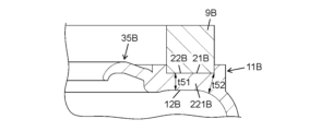
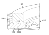
- Figure 13 is a plan view of the second case 6B of the fan case 2 of the blower 1 according to the third embodiment of the present disclosure.
- Figure 14 is a cross-sectional view of the fifth recess of the attachment surface 22B of the second case 6B.
- Figure 15 is a cross-sectional view of the sixth recess of the attachment surface of the second case 6B.
- Figure 16 is a cross-sectional view of the seventh recess of the attachment surface 22B of the second case 6B.
- the basic configuration and basic operation of the third embodiment are the same as those of the first embodiment. Therefore, the basic configuration and basic operation of the third embodiment will be described below, focusing on the differences.
- the adhesive portion 21B has a flat adhesive surface 22B.
- the seal sponge 9B is adhered to the adhesive surface 22B.
- the portion of the inner surface 12B of the case body 11B that corresponds to the pasting surface 22B has a flat or curved surface that extends smoothly along the direction in which the circular passage 31B extends.
- the distance between the pasting surface 22B and the portion of the inner surface 12B that corresponds to the pasting portion 21B of the case body 11B is the same over the entire circumference in the direction in which the circular passage 31B extends.
- "same” means that when the resin that constitutes the case body 11B is cooled and hardened after molding, the difference in thickness is only to the extent that no significant warping (deformation) occurs due to the difference in shrinkage between the portions with different thicknesses.
- the case where the thinnest part is 2 mm and the thickest part is 3 mm (1.5 times) is also included in "same" in this embodiment.
- the thickness of the thickest part is less than twice the thickness of the thinnest part.
- the former is in the range of 1.0 to 1.6 times the latter.
- the distance (first distance) between the attachment surface 22B (first location) on the side farther from the exhaust passage 32B than the circumferential center point C1 (see FIG. 13) of the circular passage 31B and the inner surface 12B is the same as the distance (second distance) between the attachment surface 22B (second location) on the side closer to the exhaust passage 32 than the circumferential center point C1 (see FIG. 13) and the inner surface 12B.
- the relationship between the adhesive portion 21B and the inner surface 12B will be specifically described with reference to Figures 14, 15, and 16.
- the first portion 221B and the second portion 222B in the following description are an example of a first location that is farther from the exhaust passage 32B than the circumferential center point C1 of the circular passage 31B.
- the third portion 223B is an example of a second location that is closer to the exhaust passage 32B than the circumferential center point C1 of the circular passage 31B.
- FIG. 14 is a cross-sectional view of the first midpoint of the circular passage 31B in FIG. 13 (cross-sectional view taken along the V-V arrow in FIG. 13), showing the first portion 221B.
- the first portion 221B is located closer to the starting point of the circular passage 31B than the circumferential center point C1.
- the inner surface 12B has a flat portion on the radially inner side and a curved surface portion on the radially outer side.
- the inner surface 12B has a radially inner thickness t51 (shortest distance between the attachment surface 22B and the inner surface 12B) and a radially outer thickness t52 (shortest distance between the attachment surface 22B and the inner surface 12B).
- FIG. 15 is a cross-sectional view of the second midpoint of the circular passage 31B in FIG. 13 (cross-sectional view taken along the line VI-VI in FIG. 13), showing the second portion 222B.
- the second portion 222B is located closer to the starting point of the circular passage 31B than the circumferential center point C1.
- the inner surface 12B has a flat portion on the radially inner side and a curved surface portion on the radially outer side.
- the inner surface 12B has a radially inner thickness t61 (shortest distance between the attachment surface 22B and the inner surface 12B) and a radially outer thickness t62 (shortest distance between the attachment surface 22B and the inner surface 12B). Thicknesses t61 and t62 are less than or equal to thicknesses t51 and t52, respectively.
- FIG. 16 is a cross-sectional view (cross-sectional view taken along the line VII-VII in FIG. 13) of the end point of the circular passage 31B or its vicinity, showing the third portion 223B.
- the third portion 223B has a planar shape that conforms to the planar shape of the inner surface 12B.
- the third portion 223B has a thickness t7 (the shortest distance between the attachment surface 22B and the inner surface 12B). The thickness t7 is less than or equal to the thicknesses t61 and t62.
- the inner surface of the case body 11B corresponding to the attachment portion has a flat shape or a smoothly curved surface shape, but may be provided with a recess.
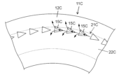
- Figure 17 is a partial plan view of the inner surface 12C of the second cover in the fourth embodiment of the present disclosure.
- the basic configuration and basic operation of the fourth embodiment are the same as those of the third embodiment. Therefore, the following description will focus on the differences.
- the attachment portion 21C has a flat attachment surface 22C.
- a plurality of individual inner recesses 15C are formed aligned in the direction in which the attachment surface 22C extends.
- the plurality of individual inner recesses 15C correspond to the attachment surface 22C and are located near the outer circumferential corners of the inner surface 12C.
- Each of the plurality of individual inner recesses 15C has a shape whose width increases as it approaches the exhaust passage side along the circumferential direction. In this way, the width of the individual inner recess 15C increases from upstream to downstream in the air flow direction. Therefore, within the individual inner recess 15C, the air moves downstream while expanding in the width direction. Therefore, the ventilation resistance caused by the individual inner recess 15C does not increase.
- the depth of the multiple individual inner recesses 15C gradually increases in the circumferential direction from the side farther from the exhaust passage to the side closer to the exhaust passage.
- the distance between the bottom surface of each individual inner recess 15C and the attachment surface 22C is substantially the same. This is because the thickness of the portion of the attachment portion 21C where the individual inner recesses 15C are not formed decreases in the circumferential direction from the side farther from the exhaust passage to the side closer to the exhaust passage.
- the distance (first distance, first thickness) between the bottom surface of the individual inner recess 15C (first location, first part) farther from the exhaust passage than the circumferential center point of the circulation passage and the attachment surface 22C may be longer than the distance (second distance, second thickness) between the bottom surface of the individual inner recess 15C (second location, second part) closer to the exhaust passage than the circumferential center point of the air passage and the inner surface 12C.
- the former is preferably less than twice the latter. It is more preferable that the former is in the range of 1.0 to 1.6 times the latter.
- the planar shape of the individual inner recesses 15C is not particularly limited.
- the number, position, and spacing of the individual inner recesses 15C are not particularly limited.
- each individual inner recess 15C may be flat, curved, or a combination of multiple surface shapes.
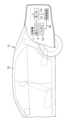
- Fig. 18 is a schematic diagram of a vehicle 51 according to a fifth embodiment of the present disclosure.
- the vehicle 51 includes a blower 1, a battery 52 (object to be cooled), a control device 53, a cable 54, a cable 56, and a vehicle body 55 (main vehicle body).
- vehicle 51 is a four-wheel hybrid vehicle in which an engine and a driving battery 52 are mounted on a vehicle body 55.
- Vehicle 51 is not limited to a hybrid vehicle, and may also be an electric vehicle.
- the vehicle 51 on which the blower 1 is mounted is not limited to a four-wheeled vehicle, but may be, for example, a vehicle (automobile) such as a two-wheeled vehicle or a three-wheeled vehicle.
- vehicle automobile
- the object to be cooled may be a part other than the battery 52.
- the vehicle body 55 is provided with a blower 1, a battery 52, a control device 53, a cable 54, and a cable 56.
- the battery 52 is, for example, a lithium ion battery, a nickel-metal hydride battery, or the like.
- the battery 52 supplies power to the blower 1, the drive motor for propelling the vehicle 51, and the like.
- the control device 53 is electrically connected to the blower 1 via a cable 54.
- the control device 53 controls the blower 1. More specifically, the control device 53 is electrically connected to the motor drive circuit of the blower 1 via a cable 54.
- the control device 53 controls the battery 52 via a cable 56. More specifically, the control device 53 controls the power supply from the battery 52 to the blower 1 and the drive motor, etc.
- the blower 1 used in the vehicle 51 functions as a cooling fan system to suppress a rise in temperature of the battery 52.
- the control device 53 controls the blower 1 to blow air from the blower 1 to the battery 52, air is sent from the blower 1 to the battery 52. This air-cools the battery 52 and suppresses a rise in temperature of the battery 52.
- the blower (1) includes a case body (11, 11A, 11B, 11C) that constitutes a part of the circulation passage (31, 31B) and the exhaust passage (32, 32B).
- the case body (11, 11A, 11B, 11C) has an annular mounting portion (21, 21A, 21B, 21C) on the outer surface of the case body (11, 11A, 11B, 11C) that is provided with a mounting surface (24, 25, 26, 24A, 25A, 26A, 22B, 22C) to which a seal member (9, 9B) is attached.
- the mounting portion (21, 21A, 21B, 21C) has, in the circumferential direction in which the circular passage (31, 31B) extends, a first location that is farther from the exhaust passage (32, 32B) than the circumferential center point (C1) of the circular passage (31, 31B), and a second location that is closer to the exhaust passage (32, 32B) than the circumferential center point (C1) of the circular passage (31, 31B).
- the first thickness of the case body (11, 11A, 11B, 11C) at the first location is equal to or greater than the second thickness of the case body (11, 11A, 11B, 11C) at the second location.
- the first thickness of the case body (11, 11A, 11B, 11C) at the first location is equal to or greater than the second thickness of the case body (11, 11A, 11B, 11C) at the second location. Therefore, the difference in thickness of the case body (11, 11A, 11B, 11C) at the mounting portion (21, 21A, 21B, 21C) in the direction in which the circulating passage (31) extends is small. Therefore, when the resin constituting the case body (11, 11A, 11B, 11C) cools and hardens after molding, warping (deformation) caused by differential shrinkage in the portions with different thicknesses is less likely to occur.
- blower (1) is obtained in which the mounting surfaces (24, 25, 26, 24A, 25A, 26A, 22B, 22C) of the case body (11, 11A, 11B, 11C) to which the sealing members (9, 9B) are attached have a high degree of flatness.
- the case body (11, 11A) has recesses (22, 22A) formed at different circumferential positions on the outer surface of the mounting portion (21, 21A).
- the recesses (22, 22A) have a first portion as a first location and a second portion as a second location.
- the first distance between the bottom surface of the first portion as the first thickness and the inner surface (12, 12A) of the case body (11, 11A) is equal to or greater than the second distance between the bottom surface of the second portion as the second thickness and the inner surface (12, 12A) of the case body (11, 11A).
- the first distance between the bottom surface of the first portion and the inner surface (12, 12A) of the case body (11, 11A) is equal to or greater than the second distance between the bottom surface of the second portion and the inner surface (12, 12A) of the case body (11, 11A). Therefore, the difference in thickness of the case body (11, 11A) in the recess (22, 22A) of the mounting portion (21, 21A) in the direction in which the circulating passage (31) extends is small.
- the recess (22, 22A) has a plurality of individual recesses (22, 22A) formed in a line in the circumferential direction at the mounting portion.
- the plurality of individual recesses (22, 22A) has a first individual recess (22, 22A) as a first portion and a second individual recess (22, 22A) as a second portion.
- the first distance between the bottom surface of the first individual recess (22, 22A) and the inner side surface (12, 12A) of the case body (11, 11A) is greater than or equal to the second distance between the bottom surface of the second individual recess (22, 22A) and the inner side surface (12, 12A) of the case body (11, 11A). Therefore, in the direction in which the circular passage (31) extends, the difference in thickness of the case body (11, 11A) at the first individual recess (22, 22A) and the second individual recess (22, 22A) is small.
- the mounting portion has a first plane (24, 24A) provided on the outer periphery of the plurality of individual recesses (22, 22A) and a second plane (25, 25A) provided on the inner periphery of the plurality of individual recesses (22, 22A).
- first plane (24, 24A) and the second plane (25, 25A) function as mounting surfaces (24, 25, 26, 24A, 25A, 26A) to which the seal member (9) is attached.
- the distance between the first plane (24, 24A) and the second plane (25, 25A) and the inner surface (12, 12A) of the case body (11, 11A) becomes shorter as they approach the exhaust passage (32) along the circumferential direction.
- the depth of the multiple individual recesses (22, 22A) becomes smaller as they approach the exhaust passage (32) along the circumferential direction.
- the difference in thickness of the case body (11, 11A) between the first individual recess (22, 22A) and the second individual recess (22, 22A) is small in the direction in which the circular passage (31) extends. Therefore, when the resin constituting the case body (11, 11A) is cooled and hardened after molding, warping (deformation) caused by the difference in shrinkage of the parts with different thicknesses is unlikely to occur. As a result, a blower (1) is obtained in which the mounting surface (24, 25, 26, 24A, 25A, 26A) of the case body (11, 11A) to which the seal member (9) is attached has a high flatness.
- the case body (11A) has a groove portion (15A) provided on the inner surface (12A) at a position corresponding to at least one of the first plane (24A) and the second plane (25A) in a plan view.
- the thickness of the case body (11A) can be reduced in the first plane (24A) and the second plane (25A).
- the mounting surface (22B) has a planar shape.
- the distance between the mounting surface (22B) and the inner surface (12B) of the case body (11B) corresponding to the mounting surface (22B) is the same at the first location and the second location.
- the thickness of the case body (11B) of the mounting portion (21B) is the same at the first and second locations in the direction in which the circulation passage (31B) extends. Therefore, when the resin constituting the case body (11B) is cooled and hardened after molding, warping (deformation) caused by differential shrinkage of the portions with different thicknesses is unlikely to occur. As a result, a blower (1) is obtained in which the mounting surface (22B) of the case body (11B) to which the seal member (9B) is attached has a high degree of flatness.
- the case body (11C) further has an inner recess (15C) formed at different circumferential positions on the inner surface (12C) of the case body (11C) corresponding to the mounting surface (22C).
- the mounting surface (22C) has a planar shape.
- the inner recess (15C) has a first portion as a first location and a second portion as a second location. The first distance between the bottom surface of the first portion as the first thickness and the mounting surface (22C) is equal to or greater than the second distance between the bottom surface of the second portion as the second thickness and the mounting surface (22C).
- the first distance between the mounting surface of the first part and the inner side surface (12C) of the case body (11C) is equal to or greater than the second distance between the mounting surface (22C) of the second part and the inner side surface (12C) of the case body (11C). Therefore, the difference in thickness of the case body (11C) in the inner recess (15C) corresponding to the mounting part (21C) in the direction in which the circulation passage (31) extends is small. Therefore, when the resin constituting the case body (11C) is cooled and hardened after molding, warping (deformation) caused by the difference in shrinkage of the parts with different thicknesses is unlikely to occur. As a result, a blower (1) is obtained in which the mounting surface (22C) of the case body (11C) to which the seal member is attached has a high flatness.
- the inner recess (15C) has a plurality of individual inner recesses (15C) formed in a line in the circumferential direction.
- the plurality of individual inner recesses (15C) have a first individual inner recess (15C) as a first portion and a second individual inner recess (15C) as a second portion.
- the first distance between the bottom surface of the first individual inner recess (15C) and the mounting surface (22C) is equal to or greater than the second distance between the bottom surface of the second individual inner recess (15C) and the mounting surface (22C). Therefore, the difference in thickness of the case body (11C) in the circumferential direction between the first individual inner recess (15C) and the second individual inner recess (15C) is small. Therefore, when the resin constituting the case body (11C) is cooled and hardened after molding, warping (deformation) caused by the difference in shrinkage of the parts with different thicknesses is unlikely to occur. As a result, a blower (1) is obtained in which the mounting surface (22C) of the case body (11C) to which the seal member is attached has a high flatness.
- the distance between the mounting surface (22C) and the inner surface (12C) of the case body (11C) becomes shorter as it approaches the exhaust passage along the circumferential direction.
- the depth of the multiple individual inner recesses (15C) becomes smaller as it approaches the exhaust passage along the circumferential direction.
- the thickness of the case body (11C) in the first individual inner recess (15C) and the second individual inner recess (15C) is uniform in the circumferential direction. Therefore, when the resin constituting the case body (11C) is cooled and hardened after molding, warping (deformation) caused by differential shrinkage in the parts with different thicknesses is unlikely to occur. As a result, a blower (1) is obtained in which the mounting surface of the case body (11C) to which the seal member is attached has a high degree of flatness.
- each of the multiple individual inner recesses (15C) has a shape whose width increases circumferentially toward the exhaust passage side.
- the width of the individual inner recess (15C) increases from upstream to downstream in the air flow direction, so that the air moves downstream while expanding in the width direction inside the individual inner recess (15C). Therefore, the ventilation resistance caused by the individual inner recess (15C) does not increase.
- the moving body (51) includes the above-mentioned blower (1), an object to be cooled (52) that is cooled by the blower (1), and a moving body (55) on which the blower (1) and the object to be cooled (52) are mounted.
- Blower 2 Fan case 3: Motor 4: Centrifugal fan 9, 9B: Seal sponge (sealing member) 11, 11A, 11B, 11C: Case body 12, 12A, 12B, 12C: Inner surface 15A: Groove portion 15C: Individual inner recess 21, 21A, 21B, 21C: Attachment portion (mounting portion) 22, 22A: individual recesses 22B, 22C: attachment surfaces (mounting surfaces) 24, 24A: Outer peripheral plane (first plane) 25, 25A: Inner peripheral plane (second plane) 31, 31B: circulation passage 32, 32B: exhaust passage 33: intake port 34: exhaust port 51: vehicle (moving body) 52: Battery (object to be cooled) 55: Vehicle body (mobile body) X1: Shaft center
Landscapes
- Engineering & Computer Science (AREA)
- Mechanical Engineering (AREA)
- General Engineering & Computer Science (AREA)
- Chemical & Material Sciences (AREA)
- Combustion & Propulsion (AREA)
- Transportation (AREA)
- Structures Of Non-Positive Displacement Pumps (AREA)
Abstract
Description
本開示は、送風機及び移動体に関する。 This disclosure relates to a blower and a moving body.
特許文献1には、ファンハウジング(ファンケース)と、ファンハウジング内に収納されたモータ及びブロワファン(遠心ファン)とを有するブロワユニット(送風機)が開示されている。ブロワユニットは、モータの回転によって遠心ファンで発生した気流を、ファンハウジングの周壁に設けられた吐出口から吐出する。
送風機の吸気口は、ダクトに接続される。送風機のケース本体とダクトとの間には、外部からの空気が送風機内に流れ込むことを防止するための環状のシールスポンジが配置される。シールスポンジは、ケース本体の環状の貼付け部に貼付けられている。 The air intake of the blower is connected to the duct. An annular seal sponge is placed between the blower case body and the duct to prevent air from the outside from flowing into the blower. The seal sponge is attached to an annular attachment part on the case body.
送風機では、気体流路の断面積が上流から下流に向かって徐々に拡大するように設計されている。それに伴って環状の貼付け部におけるケース本体の厚さも徐々に小さくなっている。その結果、ケース本体を構成する樹脂が成形後に冷却硬化するときに、厚さが異なる部分の収縮差によってケース本体に反り(変形)が生じ、貼付け部の平面度が維持されないことがある。 In a blower, the cross-sectional area of the gas flow path is designed to gradually expand from the upstream to the downstream. Accordingly, the thickness of the case body at the annular attachment part also gradually decreases. As a result, when the resin that composes the case body is cooled and hardened after molding, the difference in shrinkage of the parts with different thicknesses causes the case body to warp (deform), and the flatness of the attachment part may not be maintained.
本開示の目的は、シール部材が取付けられるケース本体の取付け部の平面度が高い送風機及び移動体を提供することにある。 The objective of this disclosure is to provide a blower and a moving body that have a high degree of flatness in the mounting portion of the case body where the sealing member is attached.
本開示の一態様に係る送風機は、周回通路と排気通路の一部を構成するケース本体を備える。前記ケース本体は、前記ケース本体の外側面において、シール部材が取付けられる取付け面が設けられた環状の取付け部を有する。前記取付け部は、前記周回通路が延びる方向において、前記周回通路の周方向中心点より前記排気通路から遠い側の第1箇所と、前記周回通路の前記周方向中心点より前記排気通路に近い側の第2箇所と、を有する。前記第1箇所における前記ケース本体の第1厚さは、前記第2箇所における前記ケース本体の第2厚さ以上である。 A blower according to one aspect of the present disclosure includes a case body that constitutes a circular passage and a part of an exhaust passage. The case body has an annular mounting portion on the outer surface of the case body, the mounting portion having a mounting surface to which a seal member is attached. The mounting portion has a first location on a side farther from the exhaust passage than the circumferential center point of the circular passage in the direction in which the circular passage extends, and a second location on a side closer to the exhaust passage than the circumferential center point of the circular passage. The first thickness of the case body at the first location is equal to or greater than the second thickness of the case body at the second location.
本開示の他の一態様に係る移動体は、前記送風機と、前記送風機によって冷却される冷却対象物と、前記送風機及び前記冷却対象物が搭載された移動体本体と、を備える。 A moving body according to another aspect of the present disclosure includes the blower, an object to be cooled by the blower, and a moving body on which the blower and the object to be cooled are mounted.
本開示によれば、シール部材が取付けられるケース本体の取付け面の平面度が高い送風機及び移動体が得られる。 This disclosure provides a blower and a moving body with a highly flat mounting surface of the case body to which the sealing member is attached.
以下、実施形態に係る送風機及び移動体について、図面を参照して説明する。下記の実施形態において説明する各図は模式的な図である。各構成要素の大きさ又は厚さそれぞれの比が必ずしも実際の寸法比を反映しているとは限らない。下記の実施形態で説明する構成は、本開示の一例にすぎない。本開示は、下記の実施形態に限定されず、本開示の効果を奏することができれば、設計等に応じて種々の変更が可能である。 The blower and moving body according to the embodiment will be described below with reference to the drawings. Each figure described in the following embodiment is a schematic diagram. The ratio of the size or thickness of each component does not necessarily reflect the actual dimensional ratio. The configuration described in the following embodiment is merely one example of the present disclosure. The present disclosure is not limited to the following embodiment, and various modifications are possible depending on the design, etc., as long as the effects of the present disclosure can be achieved.
(第1実施形態)
(1)送風機の基本構成及び基本動作
図1は、本開示の第1実施形態に係る送風機1の斜視図である。図2は、同上の送風機1の模式的断面図である。送風機1は、例えば、車両内のバッテリを冷却するための送風機である。具体的には、送風機1は、遠心ファンブロワである。
First Embodiment
(1) Basic Configuration and Operation of the Blower Fig. 1 is a perspective view of a
図1及び図2に示すように、送風機1は、主に、ファンケース2と、モータ3と、遠心ファン4と、を有する。モータ3と遠心ファン4は、ファンケース2の内部に収納されている。ファンケース2は、外気を吸い込むための吸気口33と、外部空間に向けて空気を排出するための排気口34と、吸気口33と排気口34とをつなぐ通路である周回通路31及び排気通路32と、を有している。吸気口33は円形状である。排気口34は矩形状である。空気は、吸気口33からファンケース2内部に吸い込まれ、周回通路31及び排気通路32の順番で流れ、排気口34から排出される。
As shown in Figures 1 and 2, the
モータ3は、例えば、インナーロータ型のブラシレスモータである。モータ3は、ブラシレスモータに限るものではない。モータ3は、他の形式の直流モータ又は交流モータであってもよい。モータ3として、ブラシ付きモータを用いることもできる。
The
以下、本実施形態では、モータ3が有する回転軸44の軸心X1(図2を参照)が延びる方向を軸方向と定義する。軸方向に直交する面において、軸心X1から広がる方向を径方向、軸心X1を周回する方向を周方向と定義する。
In the following, in this embodiment, the direction in which the axis X1 (see FIG. 2) of the
遠心ファン4は、互いに対向する円環状の部材の間に、複数の羽根部材が所定の間隔をあけて接続された部材である。遠心ファン4は、モータ3の回転軸44に一体で回転するように連結されている。羽根部材は、金属でも、樹脂でも形成することができる。遠心ファン4は、モータ3の回転に応じて周方向に所定の速度で回転することで、吸気口33から外気を吸入して圧送する。図3は、本開示の第1実施形態に係る送風機1のファンケース2の第2ケース6の平面図である。圧送された空気は、周回通路31を通って、図3の矢印A1、A2、A3、A4の順に、移動する。圧送された空気は、さらに排気通路32を通って、図3の矢印B1の方向に、移動する。圧送された空気は、最後に排気口34から排出される。排出された空気は、排気口34からバッテリに供給される。
The
(2)ファンケース
ファンケース2は、樹脂を成形加工してなる中空の部材である。ファンケース2は、上面に空気の吸気口33を有する。ファンケース2は、モータ3及び遠心ファン4を収容し、実質的に円筒形状である。
(2) Fan Case The
具体的には、ファンケース2は、周回通路31及び排気通路32の上壁、側壁、下壁を有する。ファンケース2は、遠心ファン4を覆うように構成されている。その構成によって、ファンケース2の内部には、遠心ファン4の外周に沿うように、周回通路31及び排気通路32が形成されている。平面視において、図3に示すように、周回通路31は遠心ファン4の外周を取り囲むように渦巻き形状である。排気通路32は直線状である。周回通路31は、モータ3から伝えられた回転動作により遠心ファン4が回転するとき、吸気口33から吸い込まれた空気を排気通路32に導くための内部空間である。周回通路31における軸心X1を含む断面の面積は、排気通路32に向かうに従って徐々に大きくなっている。
Specifically, the
吸気口33は、例えば車室内の空気の吸い込み口である。吸気口33は、実質的に円筒形のファンケース2のうち、車室に対向する側の軸方向端面(図上側の端面)に形成されている。吸気口33は、遠心ファン4とほぼ同じか又はわずかに小さい径を有した開口である。吸気口33は、ダクト10(図2を参照)を介して車室内と連通している。ダクト10は、空気を送風機1に効果的に空気を導くための部材である。
The
排気口34は、軸方向とねじれの位置の関係にある方向に開口している。つまり、遠心ファン4の軸心X1に沿う方向からファンケース2に向かって吸引された空気は、当該軸心X1とねじれの位置の関係にある方向に排気される。
The
ファンケース2は、例えばポリプロピレンなどの樹脂からなる。ファンケース2は、図1及び図2に示すように、下側の第1ケース5と、上側の第2ケース6とに分かれている。第1ケース5の外側の側面には、周方向に所定の間隔をあけて複数の突起部41が設けられている。第2ケース6の側面には、周方向に所定の間隔をあけて複数のフック42が設けられている。複数のフック42が複数の突起部41にそれぞれ係止されることで、第1ケース5と第2ケース6とが連結されている。
The
吸気口33は、第2ケース6に形成されている。排気口34は、第2ケース6と第1ケース5とが嵌め合わされて形成されている。
The
モータ3及び遠心ファン4は、第1ケース5に固定されている。
The
(3)第2ケース
図3~図11を用いて、第2ケース6を説明する。
(3) Second Case The
第2ケース6は、ケース本体11を有している。ケース本体11は、周回通路31及び排気通路32の上部を構成する部材である。第2ケース6は、主に、環状平面部35と、側面部36とを有している。環状平面部35は、吸気口33を構成する概ね平坦環状の部分である。側面部36は、環状平面部35の外周縁から軸方向に延びる概ね筒状の部分である。
The
(3-1)第2ケースの貼付け部
上述したように、図3は、本開示の第1実施形態に係る送風機1のファンケース2の第2ケース6の平面図である。図4は、同上の第2ケース6の斜視図である。図3及び図4に示すように、ケース本体11の環状平面部35の外側面(図上側面)には、環状のシールスポンジ9(シール部材)が貼り付けられる環状の貼付け部21(取付け部)が設けられている。貼付け部21には、複数の個別凹部22が、貼付け部21が延びる方向に等間隔で並んで形成されている。各個別凹部22は、平面視で概ね矩形状である。
(3-1) Adhesive Section of Second Case As described above, Fig. 3 is a plan view of the
図5は、図3の部分拡大図であり、本開示の第1実施形態に係る送風機1のファンケース2の第2ケース6の貼付け面の一部を示す図である。図5に示すように、貼付け部21は、貼付け面として、複数の個別凹部22の外周側にある外周平面24(第1平面)と、個別凹部22の内周側にある内周平面25(第2平面)と、隣接する個別凹部22同士の間を延びて外周平面24と内周平面25とを連結する複数の径方向平面26と、を更に有する。上記の構成及び複数の個別凹部22によって、貼付け部21は、平面視で格子状になっている。外周平面24の外周側には、軸方向に延びる外周突起27が設けられている。内周平面25の内周側には、軸方向に延びる内周突起28が設けられている。
5 is a partially enlarged view of FIG. 3, showing a part of the attachment surface of the
複数の個別凹部22は、周回通路31が延びる方向において、排気通路32から遠い側から排気通路32に近い側にいくに従って、徐々に深さが大きくなっている。それにより、各個別凹部22の底面と周回通路31の内側面12との距離(最短距離)が同一になっている。これは、前提構造として、排気通路32から遠い側から排気通路32に近い側にいくに従って、貼付け部21において個別凹部22が形成されていない部分の厚さ(例えば、外周平面24及び内周平面25とケース本体11の内側面12との距離)が小さくなっているからである。
The depth of the multiple
上記の構成によって、周回通路31の周方向中心点C1(図3)より排気通路32から遠い側の個別凹部22(第1箇所、第1部分)の底面と周回通路31の内側面12との距離(第1距離、第1厚さ)が、周回通路31の周方向中心点C1より排気通路32から近い側の個別凹部22(第2箇所、第2部分)の底面と周回通路31の内側面12との距離(第2距離、第2厚さ)と同一になっている。この場合、「同一」とは、ケース本体11を構成する樹脂が成形後に冷却硬化するときに、厚さが異なる部分の収縮差によって大きな反り(変形)が生じない程度の厚さの差しかないことを意味する。例えば、最も薄い部分が2mmであって最も厚い部分が3mmである場合(1.5倍)も、本実施形態では「同一」に含まれる。ただし、最も厚い部分の厚さは最も薄い部分の厚さ2倍未満であることが好ましい。さらに、前者は後者の1.0~1.6倍の範囲であることが好ましい。
With the above configuration, the distance (first distance, first thickness) between the bottom surface of the individual recess 22 (first location, first part) farther from the
以上の結果、シールスポンジ9の接着面積を十分に確保したうえで、貼付け部21と周回通路31の内側面12との距離が実質的に同一になっている部分の面積を十分に広くできる。
As a result of the above, it is possible to ensure a sufficient adhesive area for the
各個別凹部22の底面は、平面形状であってもよいし、湾曲面形状であってもよいし、複数の面形状が組み合わされていてもよい。各個別凹部22の底面は、対応する内側面12との距離が一つの個別凹部22の底面全体において均一であることが好ましい。例えば、対応する内側面12が湾曲している場合は、個別凹部22の底面は、内側面12に対応して湾曲していることが好ましい。
The bottom surface of each
(3-2)シールスポンジの変形
図6及び図7を用いて、貼付け部21におけるシールスポンジ9の変形を模式的に説明する。図6は、本開示の第1実施形態に係る送風機1のファンケース2の第2ケース6の貼付け面にシールスポンジ9が貼り付けられた構成の第1の状態を示す断面図である。図7は、本開示の第1実施形態に係る送風機1のファンケース2の第2ケース6の貼付け面にシールスポンジ9が貼り付けられた構成の第2の状態を示す断面図である。
(3-2) Deformation of Seal Sponge Deformation of the
図6では、シールスポンジ9は、貼付け部21に貼られている。より具体的には、シールスポンジ9は、外周突起27と内周突起28との間で、外周平面24、内周平面25及び複数の径方向平面26(図5を参照)に接着剤を介して貼られている。この状態では、シールスポンジ9と個別凹部22の底面との間には隙間が確保されている。
In FIG. 6, the
続いて、図7に示すように、ダクト10とケース本体11との間でシールスポンジ9が圧縮されると、シールスポンジ9の一部が個別凹部22内に入り込む。これは、シールスポンジ9の最小つぶし代T1が個別凹部22の深さD1より大きいからである。以上の結果、個別凹部22を設けても、シールスポンジ9が貼付け部21に密着する面積は減らない、又は減り方が少ない。
Next, as shown in FIG. 7, when the
シールスポンジ9は、個別凹部22の底面に密着しない構造でもよい。その場合、貼付け部21の中に占める個別凹部22の面積の割合を、適切なものに設定することが好ましい。例えば、貼付け部21の中に占める個別凹部22の面積の割合は、40~60%である。
The
(3-3)個別凹部の具体的形状
図8、図9、図10及び図11を用いて、個別凹部22の形状を具体的に説明する。図8は、本開示の第1実施形態に係る送風機1のファンケース2の第2ケース6の貼付け面の第1凹部221における断面図である。図9は、同上の貼付け面の第2凹部222における断面図である。図10は、同上の貼付け面の第3凹部223における断面図である。図11は、同上の貼付け面の第4凹部224における断面図である。以下の説明における第1凹部221及び第2凹部222は、各々、周回通路31の周方向中心点C1(図3を参照)より排気通路32から遠い側の第1箇所の一例である。第3凹部223及び第4凹部224は、各々、周回通路31の周方向中心点C1(図3を参照)より排気通路32に近い側の第2箇所の一例である。
(3-3) Specific Shape of Individual Recess The shape of the
図8は、図3において周回通路31の始点又はその周辺の断面図(図3のI-I矢視断面図)であり、第1凹部221を示している。第1凹部221の内周側部分は、内側面12の湾曲面形状に沿った湾曲面形状を有している。第1凹部221の内周側部分は、厚さt11(凹部底面と内側面12との最短距離)を有している。第1凹部221の外周側部分は、平坦な形状である。第1凹部221の外周側部分は、厚さt12(凹部底面と内側面12との最短距離)を有している。
FIG. 8 is a cross-sectional view of the start point of the
図9は、図3において周回通路31の第1中間点の断面図(図3のII-II矢視断面図)であり、第2凹部222を示している。第2凹部222は、周方向中心点C1より周回通路31の始点側に位置している。第2凹部222は、内側面12の平面形状に沿った平面形状を有し、厚さt2(凹部底面と内側面12との最短距離)を有している。厚さt2は、厚さt11、t12以下である。
FIG. 9 is a cross-sectional view of the first midpoint of the
図10は、図3において周回通路31の第2中間点の断面図(図3のIII-III矢視断面図)であり、第3凹部223を示している。第3凹部223は、周方向中心点C1より周回通路31の終点側に位置している。第3凹部223は、内側面12の湾曲面形状に沿った湾曲面形状を有し、厚さt3(凹部底面と内側面12との最短距離)を有している。厚さt3は、厚さt2以下である。
FIG. 10 is a cross-sectional view of the second midpoint of the
図11は、図3において周回通路31の終点又はその周辺の断面図(図3のIV-IV矢視断面図)であり、第4凹部224を示している。第4凹部224は、内側面12の湾曲面形状に沿った湾曲面形状を有し、厚さt4(凹部底面と内側面12との最短距離)を有している。厚さt4は、厚さt3以下である。
FIG. 11 is a cross-sectional view (cross-sectional view taken along the arrows IV-IV in FIG. 3) of the end point of the
(4)第1実施形態の変形例
複数の個別凹部22は、周回通路31の延びる方向に等間隔で配置されている。しかし、間隔は異なっていてもよい。例えば、排気通路32に近づくにつれて間隔が広くなっていってもよいし、狭くなっていってもよい。
(4) Modification of the First Embodiment The individual recesses 22 are disposed at equal intervals in the direction in which the
複数の個別凹部22は、平面視で矩形状である。しかし、複数の個別凹部22は、平面視で他の形状であってもよい。さらに、複数種類の平面形状の個別凹部が一つの貼付け面に設けられてもよい。
The multiple
複数の個別凹部22の底面は、全てが同じ面積である。しかし、面積は互いに異なっていてもよい。例えば、複数の個別凹部22の底面は、排気通路32に近づくにつれて面積が広くなっていってもよいし、狭くなっていってもよい。
The bottom surfaces of the multiple
複数の個別凹部22は、互いに分離されている。しかし、複数の個別凹部22は、周回通路31の延びる方向に沿った連結凹部によって互いに連結されていてもよい。その場合、連結凹部の幅は特に限定されない。
The individual recesses 22 are separated from one another. However, the
複数の個別凹部22は、貼付け部21の全周にわたって形成されている。しかし、複数の個別凹部22は、貼付け部21の全周の一部のみに形成されていてもよい。
The multiple
貼付け部に形成された凹部は、貼付け部の延びる方向に沿った1つの凹部でもよい。 The recess formed in the attachment portion may be a single recess along the extension direction of the attachment portion.
径方向平面26は、外周平面24及び内周平面25に接続されている。しかし、径方向平面26は、両者から離れていてもよい。つまり、径方向平面26と外周平面24及び内周平面25との間に凹部が設けられていてもよい。
The
径方向平面26は、径方向に延びている。しかし、径方向平面26は、遠心ファン4から周回通路31に向かって流れる気体の流れに沿うように、斜めに延びていてもよい。
The
(第2実施形態)
第1実施形態では、ケース本体11の内側面12は、滑らかに延びる形状を有している。しかし、ケース本体11の内側面12に、溝部が設けられていてもよい。
Second Embodiment
In the first embodiment, the
図12を用いて、上記の構造を第2実施形態として説明する。図12は、本開示の第2実施形態における第2カバーの内側面の部分平面図である。第2実施形態の基本構成及び基本動作は第1実施形態と同じである。したがって、以下、異なる点を中心に説明する。 The above structure will be described as a second embodiment using Figure 12. Figure 12 is a partial plan view of the inner surface of the second cover in the second embodiment of the present disclosure. The basic configuration and basic operation of the second embodiment are the same as those of the first embodiment. Therefore, the following description will focus on the differences.
(1)ケース本体の内側面に形成された溝部
図12では、ケース本体11Aの環状平面部35Aの内側面12Aの一部が示されている。具体的には、反対側にある貼付け部21A、複数の個別凹部22A、外周平面24A及び内周平面25Aが破線で示されている。
(1) Groove portion formed on the inner surface of the case body Fig. 12 shows a part of the
ケース本体11Aの内側面12Aには、溝部15Aが設けられている。具体的には、溝部15Aは、外周平面24Aに対応する位置(平面視において外周平面24Aの外周縁と内周縁の間)に形成された第1部分151Aと、複数の個別凹部22Aに対応する位置(平面視において径方向平面26Aの周方向両縁の間)に形成された第2部分152Aと、を有する。
A
溝部15Aの第1部分151A及び第2部分152Aは、周回通路が延びる方向において、排気通路から遠い側から排気通路に近い側にいくに従って、徐々に深さが大きくなっている。それにより、溝部15Aの第1部分151A及び第2部分152Aの底面と、貼付け部21Aの外周平面24A及び径方向平面26Aとの距離が同一になっている。これは、前提構造として、排気通路から遠い側から排気通路に近い側にいくに従って、貼付け部21Aにおいて個別凹部22Aが形成されていない部分の厚さ(外周平面24A及び内周平面25Aとケース本体11Aの内側面12Aとの距離)が小さくなっているからである。
The first and
溝部15Aによって、貼付け部21A内で個別凹部22A以外の部分におけるケース本体11Aの厚さが、個別凹部22Aにおけるケース本体11Aの厚さと等しく又は近づいている。この結果、貼付け部21Aと周回通路の内側面12Aとの距離が実質的に同一になっている部分の面積を十分に広くできる。
The
(2)第2実施形態の変形例
溝部の形状及び位置は特に限定されない。
(2) Modification of the Second Embodiment The shape and position of the groove are not particularly limited.
溝部は、外周平面及び内周平面の両方に対応した位置に形成されていてもよい。 The grooves may be formed at positions corresponding to both the outer circumferential plane and the inner circumferential plane.
溝部は、径方向平面に対応した位置に形成されていなくてもよい。溝部は、径方向面に対応した位置のみに形成されていてもよい。 The grooves do not have to be formed at positions corresponding to the radial planes. The grooves may be formed only at positions corresponding to the radial planes.
(第3実施形態)
第1実施形態及び第2実施形態では貼付け部に凹部が設けられている。しかし、貼付け部は凹部が形成されていない平面形状を有していてもよい。
Third Embodiment
In the first and second embodiments, the attachment portion is provided with a recess. However, the attachment portion may have a planar shape without a recess.
図13~図16を用いて、上記の構造を第3実施形態として説明する。図13は、本開示の第3実施形態に係る送風機1のファンケース2の第2ケース6Bの平面図である。図14は、同上の第2ケース6Bの貼付け面22Bの第5凹部における断面図である。図15は、同上の貼付け面の第6凹部における断面図である。図16は、同上の貼付け面22Bの第7凹部における断面図である。第3実施形態の基本構成及び基本動作は、第1実施形態と同じである。したがって、第3実施形態の基本構成及び基本動作は、以下、異なる点を中心に説明する。
The above structure will be described as a third embodiment using Figures 13 to 16. Figure 13 is a plan view of the
(1)ケース本体の貼付け部
貼付け部21Bは、平面状の貼付け面22Bを有している。シールスポンジ9Bは、貼付け面22Bに接着されている。
(1) Adhesive Portion of Case Body The
ケース本体11Bの内側面12Bのうち貼付け面22Bに対応する部分は、周回通路31Bが延びる方向に沿って滑らかに延びる平面又は湾曲面を有している。その結果、貼付け面22Bと、内側面12Bのうちケース本体11Bの貼付け部21Bに対応する部分との距離は、周回通路31Bの延びる方向の全周にわたって同一になっている。この場合、「同一」とは、ケース本体11Bを構成する樹脂が成形後に冷却硬化するときに、厚さが異なる部分の収縮差によって大きな反り(変形)が生じない程度の厚さの差しかないことを意味する。例えば、最も薄い部分が2mmであって最も厚い部分が3mmである場合(1.5倍)も、本実施形態では「同一」に含まれる。ただし、最も厚い部分の厚さは最も薄い部分の厚さの2倍未満であることが好ましい。さらには、前者は後者の1.0~1.6倍の範囲であることがより好ましい。
The portion of the
以上の結果、シールスポンジ9Bの接着面積を十分に確保したうえで、貼付け部21Bと周回通路31Bの内側面12Bとの距離が実質的に同一になっている部分の面積を十分に広くできる。
As a result of the above, it is possible to ensure a sufficient adhesive area for the
上記の構成によって、周回通路31Bの周方向中心点C1(図13を参照)より排気通路32Bから遠い側の貼付け面22B(第1箇所)と内側面12Bとの距離(第1距離)が、周方向中心点C1(図13を参照)より排気通路32に近い側の貼付け面22B(第2箇所)と内側面12との距離(第2距離)と同一である。
With the above configuration, the distance (first distance) between the
(2)貼付け部の具体的形状
図14、図15、及び図16を用いて、貼付け部21Bと内側面12Bとの関係を具体的に説明する。以下の説明における第1部分221B及び第2部分222Bは、周回通路31Bの周方向中心点C1より排気通路32Bから遠い側の第1箇所の一例である。第3部分223Bは、周回通路31Bの周方向中心点C1より排気通路32Bに近い側の第2箇所の一例である。
(2) Specific Shape of the Adhesive Portion The relationship between the
図14は、図13において周回通路31Bの第1中間地点の断面図(図13のV-V矢視断面図)であり、第1部分221Bを示している。第1部分221Bは、周方向中心点C1より周回通路31Bの始点側に位置している。第1部分221Bにおいて、内側面12Bは、径方向内側の平面部と径方向外側の湾曲面部を有する。内側面12Bは、径方向内側の厚さt51(貼付け面22Bと内側面12Bとの最短距離)と径方向外側の厚さt52(貼付け面22Bと内側面12Bとの最短距離)と、を有する。
FIG. 14 is a cross-sectional view of the first midpoint of the
図15は、図13において周回通路31Bの第2中間点の断面図(図13のVI-VI矢視断面図)であり、第2部分222Bを示している。第2部分222Bは、周方向中心点C1より周回通路31Bの始点側に位置している。第2部分222Bにおいて、内側面12Bは、径方向内側の平面部と径方向外側の湾曲面部を有する。内側面12Bは、径方向内側の厚さt61(貼付け面22Bと内側面12Bとの最短距離)と径方向外側の厚さt62(貼付け面22Bと内側面12Bとの最短距離)と、を有する。厚さt61、t62は、それぞれ厚さt51、t52以下である。
FIG. 15 is a cross-sectional view of the second midpoint of the
図16は、周回通路31Bの終点又はその周辺の断面図(図13のVII-VII矢視断面図)であり、第3部分223Bを示している。第3部分223Bは、内側面12Bの平面形状に沿った平面形状を有している。第3部分223Bは、厚さt7(貼付け面22Bと内側面12Bとの最短距離)を有している。厚さt7は厚さt61、t62以下である。
FIG. 16 is a cross-sectional view (cross-sectional view taken along the line VII-VII in FIG. 13) of the end point of the
(第4実施形態)
第3実施形態ではケース本体11Bのうち取付け部に対応する内側面は、平面形状又は滑らかに湾曲した湾曲面形状であるが、凹部が設けられていてもよい。
Fourth Embodiment
In the third embodiment, the inner surface of the
図17を用いて、上記の構造を第4実施形態として説明する。図17は、本開示の第4実施形態における第2カバーの内側面12Cの部分平面図である。第4実施形態の基本構成及び基本動作は第3実施形態と同じである。したがって、以下、異なる点を中心に説明する。
The above structure will be described as the fourth embodiment using Figure 17. Figure 17 is a partial plan view of the
貼付け部21Cは、平面状の貼付け面22Cを有している。
The
貼付け面22Cに対応するケース本体11Cの内側面12Cにおいて、貼付け面22Cが延びる方向に並んだ複数の個別内側凹部15Cが形成されている。複数の個別内側凹部15Cは、貼付け面22Cに対応しており、内側面12Cの外周角部付近に位置している。複数の個別内側凹部15Cの各々は、周方向に沿って排気通路側にいくに従って幅が広がる形状である。このように空気の流れ方向の上流から下流に向かって個別内側凹部15Cの幅が広がっている。よって、個別内側凹部15C内では空気は幅方向に広がりながら下流に移動する。したがって、個別内側凹部15Cに起因する通風抵抗が大きくならない。
On the
複数の個別内側凹部15Cは、周方向において、排気通路から遠い側から排気通路に近い側にいくに従って、徐々に深さが大きくなっている。それにより、各個別内側凹部15Cの底面と貼付け面22Cとの距離が実質的に同一になっている。これは、周方向に沿って排気通路から遠い側から排気通路に近い側にいくに従って、貼付け部21Cにおいて個別内側凹部15Cが形成されていない部分の厚さが小さくなっているからである。
The depth of the multiple individual
ただし、周回通路の周方向中心点より排気通路から遠い側の個別内側凹部15C(第1箇所、第1部分)の底面と貼付け面22Cとの距離(第1距離、第1厚さ)が、送風通路の周方向中心点より排気通路に近い側の個別内側凹部15C(第2箇所、第2部分)の底面と内側面12Cとの距離(第2距離、第2厚さ)より長くてもよい。なお、前者は後者の2倍未満であることが好ましい。前者は後者の1.0~1.6倍の範囲であればより好ましい。
However, the distance (first distance, first thickness) between the bottom surface of the individual
以上の結果、シールスポンジの接着面積を十分に確保したうえで、貼付け部21Cと周回通路の内側面12Cとの距離が実質的に同一になっている部分の面積を十分に広くできる。
As a result of the above, it is possible to ensure a sufficient adhesive area for the seal sponge, while also making it possible to sufficiently increase the area of the portion where the distance between the
個別内側凹部15Cの平面視形状は、特に限定されない。個別内側凹部15Cの数、位置、間隔は特に限定されない。
The planar shape of the individual
各個別内側凹部15Cの底面は、平面形状であってもよいし、湾曲面形状であってもよいし、複数の面形状が組み合わされていてもよい。
The bottom surface of each individual
(第5実施形態)
図18を用いて、第1実施形態に係る送風機1を備える車両51(移動体)を説明する。図18は、本開示の第5実施形態に係る車両51の概略図である。
Fifth Embodiment
A vehicle 51 (mobile object) including the
車両51は、図18に示すように、送風機1と、バッテリ52(冷却対象物)と、制御装置53と、ケーブル54と、ケーブル56と、車体55(移動体本体)と、を備える。
As shown in FIG. 18, the
図18では、車両51は、エンジンと駆動用のバッテリ52とが車体55に搭載された四輪のハイブリッド自動車である。車両51は、ハイブリッド自動車に限らず、電気自動車であってもよい。
In FIG. 18,
送風機1が搭載される車両51は、四輪自動車に限定されず、例えば二輪自動車、三輪自動車のような車両(自動車)でもよい。冷却対象物がバッテリ52以外のパーツであってもよい。
The
車体55には、送風機1と、バッテリ52と、制御装置53と、ケーブル54と、ケーブル56とが設けられている。
The
バッテリ52は、例えばリチウムイオン電池、ニッケル水素電池等で構成されている。バッテリ52は、送風機1、車両51を走行させるための駆動モータ等に電力を供給する。
The
制御装置53は、ケーブル54を介して、送風機1に電気的に接続されている。制御装置53は、送風機1を制御する。より詳細には、制御装置53は、ケーブル54を介して、送風機1のモータ駆動回路に電気的に接続されている。制御装置53は、ケーブル56を介してバッテリ52を制御する。より詳細には、制御装置53は、バッテリ52から送風機1及び駆動モータ等への電力供給を制御する。
The
車両51に用いられる送風機1は、バッテリ52の温度上昇を抑制するために、冷却用のファンシステムとして機能する。制御装置53から送風機1に対して、送風機1からバッテリ52に対して風を吹きつけるように制御がなされると、送風機1からバッテリ52に対して風が送り込まれる。これにより、バッテリ52が空冷され、バッテリ52の温度上昇が抑制される。
The
(実施形態同士の組み合わせ)
上述の各実施形態は、本開示の様々な実施形態の一つに過ぎない。上述の実施形態は、本開示の目的を達成できれば、設計等に応じて種々の変更が可能である。第1~第5実施形態の構成は、適宜組み合わせて適用可能である。
(Combination of the embodiments)
The above-described embodiments are merely one of various embodiments of the present disclosure. The above-described embodiments can be modified in various ways depending on the design, etc., as long as the object of the present disclosure can be achieved. The configurations of the first to fifth embodiments can be applied in appropriate combination.
(態様)
本明細書には、以下の態様が開示されている。
(Aspects)
The present specification discloses the following aspects.
第1の態様に係る送風機(1)は、周回通路(31、31B)と排気通路(32、32B)の一部を構成するケース本体(11、11A、11B、11C)を備える。ケース本体(11、11A、11B、11C)は、ケース本体(11、11A、11B、11C)の外側面において、シール部材(9、9B)が取付けられる取付け面(24、25、26、24A、25A、26A、22B、22C)が設けられた環状の取付け部(21、21A、21B、21C)を有する。取付け部(21、21A、21B、21C)は、周回通路(31、31B)が延びる周方向において、周回通路(31、31B)の周方向中心点(C1)より排気通路(32、32B)から遠い側の第1箇所と、周回通路(31、31B)の周方向中心点(C1)より排気通路(32、32B)に近い側の第2箇所と、を有する。第1箇所におけるケース本体(11、11A、11B、11C)の第1厚さは、第2箇所におけるケース本体(11、11A、11B、11C)の第2厚さ以上である。 The blower (1) according to the first aspect includes a case body (11, 11A, 11B, 11C) that constitutes a part of the circulation passage (31, 31B) and the exhaust passage (32, 32B). The case body (11, 11A, 11B, 11C) has an annular mounting portion (21, 21A, 21B, 21C) on the outer surface of the case body (11, 11A, 11B, 11C) that is provided with a mounting surface (24, 25, 26, 24A, 25A, 26A, 22B, 22C) to which a seal member (9, 9B) is attached. The mounting portion (21, 21A, 21B, 21C) has, in the circumferential direction in which the circular passage (31, 31B) extends, a first location that is farther from the exhaust passage (32, 32B) than the circumferential center point (C1) of the circular passage (31, 31B), and a second location that is closer to the exhaust passage (32, 32B) than the circumferential center point (C1) of the circular passage (31, 31B). The first thickness of the case body (11, 11A, 11B, 11C) at the first location is equal to or greater than the second thickness of the case body (11, 11A, 11B, 11C) at the second location.
この態様によれば、取付け部(21、21A、21B、21C)において、第1箇所におけるケース本体(11、11A、11B、11C)の第1厚さが、第2箇所におけるケース本体(11、11A、11B、11C)の第2厚さ以上である。したがって、周回通路(31)が延びる方向において取付け部(21、21A、21B、21C)のケース本体(11、11A、11B、11C)厚さの差が小さくなる。そのため、ケース本体(11、11A、11B、11C)を構成する樹脂が成形後に冷却硬化するときに、厚さが異なる部分の収縮差を起因とする反り(変形)が生じにくい。その結果、シール部材(9,9B)が取付けられるケース本体(11、11A、11B、11C)の取付け面(24、25、26、24A、25A、26A、22B、22C)の平面度が高い送風機(1)が得られる。 According to this embodiment, in the mounting portion (21, 21A, 21B, 21C), the first thickness of the case body (11, 11A, 11B, 11C) at the first location is equal to or greater than the second thickness of the case body (11, 11A, 11B, 11C) at the second location. Therefore, the difference in thickness of the case body (11, 11A, 11B, 11C) at the mounting portion (21, 21A, 21B, 21C) in the direction in which the circulating passage (31) extends is small. Therefore, when the resin constituting the case body (11, 11A, 11B, 11C) cools and hardens after molding, warping (deformation) caused by differential shrinkage in the portions with different thicknesses is less likely to occur. As a result, a blower (1) is obtained in which the mounting surfaces (24, 25, 26, 24A, 25A, 26A, 22B, 22C) of the case body (11, 11A, 11B, 11C) to which the sealing members (9, 9B) are attached have a high degree of flatness.
第2の態様に係る送風機(1)では、第1の態様において、ケース本体(11、11A)は、取付け部(21、21A)の外側面において、周方向の異なる位置にわたって形成された凹部(22、22A)を有する。凹部(22、22A)は、第1箇所としての第1部分と、第2箇所としての第2部分と、を有する。第1厚さとしての第1部分の底面とケース本体(11、11A)の内側面(12、12A)との間の第1距離は、第2厚さとしての第2部分の底面とケース本体(11、11A)の内側面(12、12A)との間の第2距離以上である。 In the blower (1) according to the second aspect, in the first aspect, the case body (11, 11A) has recesses (22, 22A) formed at different circumferential positions on the outer surface of the mounting portion (21, 21A). The recesses (22, 22A) have a first portion as a first location and a second portion as a second location. The first distance between the bottom surface of the first portion as the first thickness and the inner surface (12, 12A) of the case body (11, 11A) is equal to or greater than the second distance between the bottom surface of the second portion as the second thickness and the inner surface (12, 12A) of the case body (11, 11A).
この態様によれば、取付け部(21、21A)に設けられた凹部(22、22A)において、第1部分の底面とケース本体(11、11A)の内側面(12、12A)との間の第1距離が、第2部分の底面とケース本体(11、11A)の内側面(12、12A)との間の第2距離以上である。したがって、周回通路(31)が延びる方向において取付け部(21、21A)の凹部(22、22A)におけるケース本体(11、11A)厚さの差が小さくなる。そのため、ケース本体(11、11A)を構成する樹脂が成形後に冷却硬化するときに、厚さが異なる部分の収縮差を起因とする反り(変形)が生じにくい。その結果、シール部材(9)が取付けられるケース本体(11、11A)の取付け面(24、25、26、24A、25A、26A)の平面度が高い送風機(1)が得られる。 According to this aspect, in the recess (22, 22A) provided in the mounting portion (21, 21A), the first distance between the bottom surface of the first portion and the inner surface (12, 12A) of the case body (11, 11A) is equal to or greater than the second distance between the bottom surface of the second portion and the inner surface (12, 12A) of the case body (11, 11A). Therefore, the difference in thickness of the case body (11, 11A) in the recess (22, 22A) of the mounting portion (21, 21A) in the direction in which the circulating passage (31) extends is small. Therefore, when the resin constituting the case body (11, 11A) cools and hardens after molding, warping (deformation) caused by the difference in shrinkage of the portions with different thicknesses is less likely to occur. As a result, a blower (1) is obtained in which the mounting surfaces (24, 25, 26, 24A, 25A, 26A) of the case body (11, 11A) to which the seal member (9) is attached have a high degree of flatness.
第3の態様に係る送風機では、第2の態様において、凹部(22、22A)は、取付け部において、周方向に並んで形成された複数の個別凹部(22、22A)を有する。複数の個別凹部(22、22A)は、第1部分としての第1個別凹部(22、22A)と、第2部分としての第2個別凹部(22、22A)と、を有する。 In the blower according to the third aspect, in the second aspect, the recess (22, 22A) has a plurality of individual recesses (22, 22A) formed in a line in the circumferential direction at the mounting portion. The plurality of individual recesses (22, 22A) has a first individual recess (22, 22A) as a first portion and a second individual recess (22, 22A) as a second portion.
この態様によれば、第1個別凹部(22、22A)の底面とケース本体(11、11A)の内側面(12、12A)との間の第1距離が、第2個別凹部(22、22A)の底面とケース本体(11、11A)の内側面(12、12A)との間の第2距離以上である。したがって、周回通路(31)が延びる方向において、第1個別凹部(22、22A)及び第2個別凹部(22、22A)におけるケース本体(11、11A)の厚さの差が小さくなる。そのため、ケース本体(11、11A)を構成する樹脂が成形後に冷却硬化するときに、厚さが異なる部分の収縮差を起因とする反り(変形)が生じにくい。その結果、シール部材(9)が取付けられるケース本体(11、11A)の取付け面(24、25、26、24A、25A、26A)の平面度が高い送風機(1)が得られる。 According to this aspect, the first distance between the bottom surface of the first individual recess (22, 22A) and the inner side surface (12, 12A) of the case body (11, 11A) is greater than or equal to the second distance between the bottom surface of the second individual recess (22, 22A) and the inner side surface (12, 12A) of the case body (11, 11A). Therefore, in the direction in which the circular passage (31) extends, the difference in thickness of the case body (11, 11A) at the first individual recess (22, 22A) and the second individual recess (22, 22A) is small. Therefore, when the resin constituting the case body (11, 11A) cools and hardens after molding, warping (deformation) caused by differential shrinkage of parts with different thicknesses is less likely to occur. As a result, a blower (1) is obtained in which the mounting surfaces (24, 25, 26, 24A, 25A, 26A) of the case body (11, 11A) to which the seal member (9) is attached have a high degree of flatness.
第4の態様に係る送風機(1)では、第3の態様において、取付け部は、複数の個別凹部(22、22A)の外周側に設けられた第1平面(24、24A)と、複数の個別凹部(22、22A)の内周側に設けられた第2平面(25、25A)と、を有する。 In the blower (1) according to the fourth aspect, in the third aspect, the mounting portion has a first plane (24, 24A) provided on the outer periphery of the plurality of individual recesses (22, 22A) and a second plane (25, 25A) provided on the inner periphery of the plurality of individual recesses (22, 22A).
この態様によれば、第1平面(24、24A)及び第2平面(25、25A)はシール部材(9)が取付けられる取付け面(24、25、26、24A、25A、26A)として機能する。 In this embodiment, the first plane (24, 24A) and the second plane (25, 25A) function as mounting surfaces (24, 25, 26, 24A, 25A, 26A) to which the seal member (9) is attached.
第5の態様に係る送風機(1)では、第4の態様において、第1平面(24、24A)及び第2平面(25、25A)とケース本体(11、11A)の内側面(12、12A)との距離は、周方向に沿って排気通路(32)に近づくにつれて短くなっていく。複数の個別凹部(22、22A)の深さは、周方向に沿って排気通路(32)に近づくにつれて小さくなっていく。 In the blower (1) according to the fifth aspect, in the fourth aspect, the distance between the first plane (24, 24A) and the second plane (25, 25A) and the inner surface (12, 12A) of the case body (11, 11A) becomes shorter as they approach the exhaust passage (32) along the circumferential direction. The depth of the multiple individual recesses (22, 22A) becomes smaller as they approach the exhaust passage (32) along the circumferential direction.
この態様によれば、周回通路(31)が延びる方向において、第1個別凹部(22、22A)及び第2個別凹部(22、22A)におけるケース本体(11、11A)の厚さの差が小さくなる。そのため、ケース本体(11、11A)を構成する樹脂が成形後に冷却硬化するときに、厚さが異なる部分の収縮差を起因とする反り(変形)が生じにくい。その結果、シール部材(9)が取付けられるケース本体(11、11A)の取付け面(24、25、26、24A、25A、26A)の平面度が高い送風機(1)が得られる。 According to this embodiment, the difference in thickness of the case body (11, 11A) between the first individual recess (22, 22A) and the second individual recess (22, 22A) is small in the direction in which the circular passage (31) extends. Therefore, when the resin constituting the case body (11, 11A) is cooled and hardened after molding, warping (deformation) caused by the difference in shrinkage of the parts with different thicknesses is unlikely to occur. As a result, a blower (1) is obtained in which the mounting surface (24, 25, 26, 24A, 25A, 26A) of the case body (11, 11A) to which the seal member (9) is attached has a high flatness.
第6の態様に係る送風機(1)では、第4又は第5の態様において、ケース本体(11A)は、内側面(12A)において、平面視において、第1平面(24A)及び第2平面(25A)の少なくとも一方に対応する位置に設けられた溝部(15A)を有する。 In the blower (1) according to the sixth aspect, in the fourth or fifth aspect, the case body (11A) has a groove portion (15A) provided on the inner surface (12A) at a position corresponding to at least one of the first plane (24A) and the second plane (25A) in a plan view.
この態様によれば、第1平面(24A)及び第2平面(25A)において、ケース本体(11A)の厚さを減らすことができる。 According to this embodiment, the thickness of the case body (11A) can be reduced in the first plane (24A) and the second plane (25A).
第7の態様に係る送風機(1)では、第1の態様において、取付け面(22B)は、平面形状を有する。取付け面(22B)と取付け面(22B)に対応するケース本体(11B)の内側面(12B)との距離は、第1箇所と第2箇所とで同一である。 In the seventh embodiment of the blower (1), in the first embodiment, the mounting surface (22B) has a planar shape. The distance between the mounting surface (22B) and the inner surface (12B) of the case body (11B) corresponding to the mounting surface (22B) is the same at the first location and the second location.
この態様によれば、周回通路(31B)が延びる方向において、取付け部(21B)のケース本体(11B)の厚さが第1箇所と第2箇所で同一になる。そのため、ケース本体(11B)を構成する樹脂が成形後に冷却硬化するときに、厚さが異なる部分の収縮差を起因とする反り(変形)が生じにくい。その結果、シール部材(9B)が取付けられるケース本体(11B)の取付け面(22B)の平面度が高い送風機(1)が得られる。 In this embodiment, the thickness of the case body (11B) of the mounting portion (21B) is the same at the first and second locations in the direction in which the circulation passage (31B) extends. Therefore, when the resin constituting the case body (11B) is cooled and hardened after molding, warping (deformation) caused by differential shrinkage of the portions with different thicknesses is unlikely to occur. As a result, a blower (1) is obtained in which the mounting surface (22B) of the case body (11B) to which the seal member (9B) is attached has a high degree of flatness.
第8の態様に係る送風機(1)では、第1の態様において、ケース本体(11C)は、取付け面(22C)に対応するケース本体(11C)の内側面(12C)において、周方向の異なる位置にわたって形成された内側凹部(15C)を更に有する。取付け面(22C)は、平面形状を有する。内側凹部(15C)は、第1箇所としての第1部分と、第2箇所としての第2部分と、を有する。第1厚さとしての第1部分の底面と取付け面(22C)との間の第1距離は、第2厚さとしての第2部分の底面と取付け面(22C)との間の第2距離以上である。 In the blower (1) according to the eighth aspect, in the first aspect, the case body (11C) further has an inner recess (15C) formed at different circumferential positions on the inner surface (12C) of the case body (11C) corresponding to the mounting surface (22C). The mounting surface (22C) has a planar shape. The inner recess (15C) has a first portion as a first location and a second portion as a second location. The first distance between the bottom surface of the first portion as the first thickness and the mounting surface (22C) is equal to or greater than the second distance between the bottom surface of the second portion as the second thickness and the mounting surface (22C).
この態様によれば、ケース本体(11C)の内側凹部(15C)において、第1部分の取付け面とケース本体(11C)の内側面(12C)との間の第1距離が、第2部分の取付け面(22C)とケース本体(11C)の内側面(12C)との間の第2距離以上である。したがって、周回通路(31)が延びる方向において取付け部(21C)に対応する内側凹部(15C)におけるケース本体(11C)の厚さの差が小さくなる。そのため、ケース本体(11C)を構成する樹脂が成形後に冷却硬化するときに、厚さが異なる部分の収縮差を起因とする反り(変形)が生じにくい。その結果、シール部材が取付けられるケース本体(11C)の取付け面(22C)の平面度が高い送風機(1)が得られる。 According to this embodiment, in the inner recess (15C) of the case body (11C), the first distance between the mounting surface of the first part and the inner side surface (12C) of the case body (11C) is equal to or greater than the second distance between the mounting surface (22C) of the second part and the inner side surface (12C) of the case body (11C). Therefore, the difference in thickness of the case body (11C) in the inner recess (15C) corresponding to the mounting part (21C) in the direction in which the circulation passage (31) extends is small. Therefore, when the resin constituting the case body (11C) is cooled and hardened after molding, warping (deformation) caused by the difference in shrinkage of the parts with different thicknesses is unlikely to occur. As a result, a blower (1) is obtained in which the mounting surface (22C) of the case body (11C) to which the seal member is attached has a high flatness.
第9の態様に係る送風機(1)では、第8の態様において、内側凹部(15C)は、周方向に並んで形成された複数の個別内側凹部(15C)を有する。複数の個別内側凹部(15C)は、第1部分としての第1個別内側凹部(15C)と、第2部分としての第2個別内側凹部(15C)と、を有する。 In the blower (1) according to the ninth aspect, in the eighth aspect, the inner recess (15C) has a plurality of individual inner recesses (15C) formed in a line in the circumferential direction. The plurality of individual inner recesses (15C) have a first individual inner recess (15C) as a first portion and a second individual inner recess (15C) as a second portion.
この態様によれば、第1個別内側凹部(15C)の底面と取付け面(22C)との間の第1距離が、第2個別内側凹部(15C)の底面と取付け面(22C)との間の第2距離以上である。したがって、周方向において第1個別内側凹部(15C)及び第2個別内側凹部(15C)におけるケース本体(11C)の厚さの差が小さくなる。そのため、ケース本体(11C)を構成する樹脂が成形後に冷却硬化するときに、厚さが異なる部分の収縮差を起因とする反り(変形)が生じにくい。その結果、シール部材が取付けられるケース本体(11C)の取付け面(22C)の平面度が高い送風機(1)が得られる。 According to this embodiment, the first distance between the bottom surface of the first individual inner recess (15C) and the mounting surface (22C) is equal to or greater than the second distance between the bottom surface of the second individual inner recess (15C) and the mounting surface (22C). Therefore, the difference in thickness of the case body (11C) in the circumferential direction between the first individual inner recess (15C) and the second individual inner recess (15C) is small. Therefore, when the resin constituting the case body (11C) is cooled and hardened after molding, warping (deformation) caused by the difference in shrinkage of the parts with different thicknesses is unlikely to occur. As a result, a blower (1) is obtained in which the mounting surface (22C) of the case body (11C) to which the seal member is attached has a high flatness.
第10の態様に係る送風機(1)では、第9の態様において、取付け面(22C)とケース本体(11C)の内側面(12C)との距離は、周方向に沿って排気通路に近づくにつれて短くなっていく。複数の個別内側凹部(15C)の深さは、周方向に沿って排気通路に近づくにつれて小さくなっていく。 In the blower (1) according to the tenth aspect, in the ninth aspect, the distance between the mounting surface (22C) and the inner surface (12C) of the case body (11C) becomes shorter as it approaches the exhaust passage along the circumferential direction. The depth of the multiple individual inner recesses (15C) becomes smaller as it approaches the exhaust passage along the circumferential direction.
この態様によれば、周方向において第1個別内側凹部(15C)及び第2個別内側凹部(15C)におけるケース本体(11C)の厚さが均一になる。そのため、ケース本体(11C)を構成する樹脂が成形後に冷却硬化するときに、厚さが異なる部分の収縮差を起因とする反り(変形)が生じにくい。その結果、シール部材が取付けられるケース本体(11C)の取付け面の平面度が高い送風機(1)が得られる。 According to this embodiment, the thickness of the case body (11C) in the first individual inner recess (15C) and the second individual inner recess (15C) is uniform in the circumferential direction. Therefore, when the resin constituting the case body (11C) is cooled and hardened after molding, warping (deformation) caused by differential shrinkage in the parts with different thicknesses is unlikely to occur. As a result, a blower (1) is obtained in which the mounting surface of the case body (11C) to which the seal member is attached has a high degree of flatness.
第11の態様に係る送風機(1)では、第9又は第10の態様において、複数の個別内側凹部(15C)の各々は、周方向に沿って排気通路側に向かって幅が広がる形状を有する。 In the blower (1) according to the eleventh aspect, in the ninth or tenth aspect, each of the multiple individual inner recesses (15C) has a shape whose width increases circumferentially toward the exhaust passage side.
この態様によれば、空気の流れ方向の上流から下流に向かって個別内側凹部(15C)の幅が広がっているので、個別内側凹部(15C)内では空気は幅方向に広がりながら下流に移動する。したがって、個別内側凹部(15C)に起因する通風抵抗が大きくならない。 In this embodiment, the width of the individual inner recess (15C) increases from upstream to downstream in the air flow direction, so that the air moves downstream while expanding in the width direction inside the individual inner recess (15C). Therefore, the ventilation resistance caused by the individual inner recess (15C) does not increase.
第12の態様に係る移動体(51)は、上記の送風機(1)と、送風機(1)によって冷却される冷却対象物(52)と、送風機(1)及び冷却対象物(52)が搭載された移動体本体(55)と、を備える。 The moving body (51) according to the twelfth aspect includes the above-mentioned blower (1), an object to be cooled (52) that is cooled by the blower (1), and a moving body (55) on which the blower (1) and the object to be cooled (52) are mounted.
この態様によれば、移動体(51)において上記の送風機(1)による効果が得られる。 In this embodiment, the effects of the blower (1) described above can be obtained in the moving body (51).
1:送風機
2:ファンケース
3:モータ
4:遠心ファン
9、9B:シールスポンジ(シール部材)
11、11A、11B、11C:ケース本体
12、12A、12B、12C:内側面
15A:溝部
15C:個別内側凹部
21、21A、21B、21C:貼付け部(取付け部)
22、22A:個別凹部
22B、22C:貼付け面(取付け面)
24、24A:外周平面(第1平面)
25、25A:内周平面(第2平面)
31、31B:周回通路
32、32B:排気通路
33:吸気口
34:排気口
51:車両(移動体)
52:バッテリ(冷却対象物)
55:車体(移動体本体)
X1:軸心
1: Blower 2: Fan case 3: Motor 4:
11, 11A, 11B, 11C:
22, 22A:
24, 24A: Outer peripheral plane (first plane)
25, 25A: Inner peripheral plane (second plane)
31, 31B:
52: Battery (object to be cooled)
55: Vehicle body (mobile body)
X1: Shaft center
Claims (12)
前記ケース本体は、前記ケース本体の外側面において、シール部材が取付けられる取付け面が設けられた環状の取付け部を有し、
前記取付け部は、前記周回通路が延びる周方向において、前記周回通路の周方向中心点より前記排気通路から遠い側の第1箇所と、前記周回通路の前記周方向中心点より前記排気通路に近い側の第2箇所と、を有し、
前記第1箇所における前記ケース本体の第1厚さは、前記第2箇所における前記ケース本体の第2厚さ以上である、
送風機。 A case body is provided that constitutes a circulation passage and a part of an exhaust passage,
the case body has an annular mounting portion provided on an outer surface of the case body with a mounting surface to which a seal member is attached,
the attachment portion has, in a circumferential direction in which the circular passage extends, a first location that is farther from the exhaust passage than a circumferential center point of the circular passage, and a second location that is closer to the exhaust passage than the circumferential center point of the circular passage,
A first thickness of the case body at the first location is greater than or equal to a second thickness of the case body at the second location.
Blower.
前記凹部は、
前記第1箇所としての第1部分と、
前記第2箇所としての第2部分と、を有し、
前記第1厚さとしての前記第1部分の底面と前記ケース本体の内側面との間の第1距離は、前記第2厚さとしての前記第2部分の底面と前記ケース本体の前記内側面との間の第2距離以上である、
請求項1に記載の送風機。 the case body has recesses formed in the outer surface of the attachment portion at different positions in the circumferential direction,
The recessed portion is
A first portion as the first location;
A second portion as the second location,
A first distance between a bottom surface of the first portion as the first thickness and an inner surface of the case body is equal to or greater than a second distance between a bottom surface of the second portion as the second thickness and the inner surface of the case body.
The blower of claim 1.
前記複数の個別凹部は、
前記第1部分としての第1個別凹部と、
前記第2部分としての第2個別凹部と、を有する、
請求項2に記載の送風機。 The recess includes a plurality of individual recesses formed in the mounting portion and aligned in the circumferential direction,
The plurality of individual recesses include
a first individual recess as the first portion;
and a second individual recess as the second portion.
The blower of claim 2.
前記複数の個別凹部の外周側に設けられた第1平面と、
前記複数の個別凹部の内周側に設けられた第2平面と、を有する、
請求項3に記載の送風機。 The mounting portion is
a first plane provided on an outer circumferential side of the plurality of individual recesses;
and a second plane provided on an inner circumferential side of the plurality of individual recesses.
The blower of claim 3.
前記複数の個別凹部の深さは、前記周方向に沿って前記排気通路に近づくにつれて小さくなっていく、
請求項4に記載の送風機。 a distance between the first plane and the second plane and the inner surface of the case body becomes shorter as the distance approaches the exhaust passage along the circumferential direction,
The depth of the individual recesses decreases toward the exhaust passage along the circumferential direction.
The blower of claim 4.
請求項4又は5に記載の送風機。 The case body has a groove portion provided on the inner surface at a position corresponding to at least one of the first plane and the second plane in a plan view.
A blower according to claim 4 or 5.
前記取付け面と前記取付け面に対応する前記ケース本体の内側面との距離は、前記第1箇所と前記第2箇所とで同一である、
請求項1に記載の送風機。 The mounting surface has a planar shape,
a distance between the mounting surface and an inner surface of the case main body corresponding to the mounting surface is the same at the first location and the second location;
The blower of claim 1.
前記取付け面は、平面形状を有しており、
前記内側凹部は、
前記第1箇所としての第1部分と、
前記第2箇所としての第2部分と、を有し、
前記第1厚さとしての前記第1部分の底面と前記取付け面との間の第1距離は、前記第2厚さとしての前記第2部分の底面と前記取付け面との間の第2距離以上である、
請求項1に記載の送風機。 The case body further includes an inner recess formed at different positions in the circumferential direction on an inner surface thereof corresponding to the mounting surface,
The mounting surface has a planar shape,
The inner recess is
A first portion as the first location;
A second portion as the second location,
a first distance between a bottom surface of the first portion at the first thickness and the mounting surface is equal to or greater than a second distance between a bottom surface of the second portion at the second thickness and the mounting surface;
The blower of claim 1.
前記複数の個別内側凹部は、
前記第1部分としての第1個別内側凹部と、
前記第2部分としての第2個別内側凹部と、を有する、
請求項8に記載の送風機。 The inner recess includes a plurality of individual inner recesses formed side by side in the circumferential direction,
The plurality of individual inner recesses include
a first individual inner recess as the first portion;
and a second individual inner recess as the second portion.
The blower of claim 8.
前記複数の個別内側凹部の深さは、前記周方向に沿って前記排気通路に近づくにつれて小さくなっていく、
請求項9に記載の送風機。 a distance between the mounting surface and the inner surface of the case body becomes shorter along the circumferential direction toward the exhaust passage,
a depth of the individual inner recesses decreases toward the exhaust passage along the circumferential direction;
The blower of claim 9.
請求項9又は10に記載の送風機。 Each of the plurality of individual inner recesses has a shape whose width increases toward the exhaust passage along the circumferential direction.
A blower according to claim 9 or 10.
前記送風機により冷却される冷却対象物と、
前記送風機及び前記冷却対象物が搭載された移動体本体と、を備える、
移動体。 A blower according to any one of claims 1 to 5 and 7 to 9;
An object to be cooled by the blower; and
a moving body on which the blower and the object to be cooled are mounted,
Mobile body.
Priority Applications (2)
| Application Number | Priority Date | Filing Date | Title |
|---|---|---|---|
| JP2025527600A JPWO2024257562A1 (en) | 2023-06-16 | 2024-05-21 | |
| CN202480036927.2A CN121219499A (en) | 2023-06-16 | 2024-05-21 | Fans and mobile bodies |
Applications Claiming Priority (2)
| Application Number | Priority Date | Filing Date | Title |
|---|---|---|---|
| JP2023-099509 | 2023-06-16 | ||
| JP2023099509 | 2023-06-16 |
Publications (1)
| Publication Number | Publication Date |
|---|---|
| WO2024257562A1 true WO2024257562A1 (en) | 2024-12-19 |
Family
ID=93851818
Family Applications (1)
| Application Number | Title | Priority Date | Filing Date |
|---|---|---|---|
| PCT/JP2024/018689 Ceased WO2024257562A1 (en) | 2023-06-16 | 2024-05-21 | Blower and moving body |
Country Status (3)
| Country | Link |
|---|---|
| JP (1) | JPWO2024257562A1 (en) |
| CN (1) | CN121219499A (en) |
| WO (1) | WO2024257562A1 (en) |
Citations (2)
| Publication number | Priority date | Publication date | Assignee | Title |
|---|---|---|---|---|
| JP2019065739A (en) * | 2017-09-29 | 2019-04-25 | 新明和工業株式会社 | pump |
| JP2020204274A (en) * | 2019-06-14 | 2020-12-24 | 株式会社マキタ | Blower |
-
2024
- 2024-05-21 JP JP2025527600A patent/JPWO2024257562A1/ja active Pending
- 2024-05-21 CN CN202480036927.2A patent/CN121219499A/en active Pending
- 2024-05-21 WO PCT/JP2024/018689 patent/WO2024257562A1/en not_active Ceased
Patent Citations (2)
| Publication number | Priority date | Publication date | Assignee | Title |
|---|---|---|---|---|
| JP2019065739A (en) * | 2017-09-29 | 2019-04-25 | 新明和工業株式会社 | pump |
| JP2020204274A (en) * | 2019-06-14 | 2020-12-24 | 株式会社マキタ | Blower |
Also Published As
| Publication number | Publication date |
|---|---|
| JPWO2024257562A1 (en) | 2024-12-19 |
| CN121219499A (en) | 2025-12-26 |
Similar Documents
| Publication | Publication Date | Title |
|---|---|---|
| KR101799123B1 (en) | Centrifugal blower assembly | |
| KR101119749B1 (en) | Electric fan for vehicle use | |
| JP4479799B2 (en) | Vehicle alternator | |
| JP6931774B2 (en) | Temperature control system, vehicle | |
| JP6751854B2 (en) | Temperature control unit, temperature control system, vehicle | |
| JP6652077B2 (en) | Centrifugal blower | |
| US20150118037A1 (en) | Centrifugal fan | |
| JP6818443B2 (en) | Electric blower and vacuum cleaner equipped with it | |
| US11332052B2 (en) | Centrifugal blower device | |
| US20190390676A1 (en) | Centrifugal blower device | |
| US20200127345A2 (en) | Temperature conditioning unit, temperature conditioning system, and vehicle | |
| CN107431392A (en) | Rotor assembly and motor including the rotor assembly | |
| WO2024257562A1 (en) | Blower and moving body | |
| US11448077B2 (en) | Method for manufacturing turbo fan | |
| JP2019077439A (en) | Blower motor assembly | |
| CN118922632A (en) | Fan and moving body | |
| WO2026048383A1 (en) | Blower | |
| CN213817433U (en) | Motor and fuel cell engine system | |
| JP6690603B2 (en) | Centrifugal blower | |
| JP7760897B2 (en) | blower | |
| JP5724380B2 (en) | Axial fan | |
| CN121969839A (en) | Fan housing, fan and moving body | |
| WO2025211087A1 (en) | Blower and moving body | |
| WO2023188813A1 (en) | Blower and moving body | |
| CN121605248A (en) | Fans and mobile bodies |
Legal Events
| Date | Code | Title | Description |
|---|---|---|---|
| 121 | Ep: the epo has been informed by wipo that ep was designated in this application |
Ref document number: 24823184 Country of ref document: EP Kind code of ref document: A1 |
|
| ENP | Entry into the national phase |
Ref document number: 2025527600 Country of ref document: JP Kind code of ref document: A |
|
| WWE | Wipo information: entry into national phase |
Ref document number: 2025527600 Country of ref document: JP |
|
| NENP | Non-entry into the national phase |
Ref country code: DE |