WO2024257562A1 - Soufflante et corps mobile - Google Patents
Soufflante et corps mobile Download PDFInfo
- Publication number
- WO2024257562A1 WO2024257562A1 PCT/JP2024/018689 JP2024018689W WO2024257562A1 WO 2024257562 A1 WO2024257562 A1 WO 2024257562A1 JP 2024018689 W JP2024018689 W JP 2024018689W WO 2024257562 A1 WO2024257562 A1 WO 2024257562A1
- Authority
- WO
- WIPO (PCT)
- Prior art keywords
- blower
- case body
- individual
- recess
- exhaust passage
- Prior art date
- Legal status (The legal status is an assumption and is not a legal conclusion. Google has not performed a legal analysis and makes no representation as to the accuracy of the status listed.)
- Ceased
Links
Images


Classifications
-
- B—PERFORMING OPERATIONS; TRANSPORTING
- B60—VEHICLES IN GENERAL
- B60K—ARRANGEMENT OR MOUNTING OF PROPULSION UNITS OR OF TRANSMISSIONS IN VEHICLES; ARRANGEMENT OR MOUNTING OF PLURAL DIVERSE PRIME-MOVERS IN VEHICLES; AUXILIARY DRIVES FOR VEHICLES; INSTRUMENTATION OR DASHBOARDS FOR VEHICLES; ARRANGEMENTS IN CONNECTION WITH COOLING, AIR INTAKE, GAS EXHAUST OR FUEL SUPPLY OF PROPULSION UNITS IN VEHICLES
- B60K11/00—Arrangement in connection with cooling of propulsion units
- B60K11/06—Arrangement in connection with cooling of propulsion units with air cooling
-
- F—MECHANICAL ENGINEERING; LIGHTING; HEATING; WEAPONS; BLASTING
- F04—POSITIVE - DISPLACEMENT MACHINES FOR LIQUIDS; PUMPS FOR LIQUIDS OR ELASTIC FLUIDS
- F04D—NON-POSITIVE-DISPLACEMENT PUMPS
- F04D29/00—Details, component parts, or accessories
- F04D29/40—Casings; Connections of working fluid
- F04D29/42—Casings; Connections of working fluid for radial or helico-centrifugal pumps
- F04D29/44—Fluid-guiding means, e.g. diffusers
-
- F—MECHANICAL ENGINEERING; LIGHTING; HEATING; WEAPONS; BLASTING
- F04—POSITIVE - DISPLACEMENT MACHINES FOR LIQUIDS; PUMPS FOR LIQUIDS OR ELASTIC FLUIDS
- F04D—NON-POSITIVE-DISPLACEMENT PUMPS
- F04D29/00—Details, component parts, or accessories
- F04D29/60—Mounting; Assembling; Disassembling
- F04D29/62—Mounting; Assembling; Disassembling of radial or helico-centrifugal pumps
Definitions
- This disclosure relates to a blower and a moving body.
- Patent Document 1 discloses a blower unit (air blower) having a fan housing (fan case) and a motor and blower fan (centrifugal fan) housed within the fan housing.
- the blower unit discharges airflow generated by the centrifugal fan through an outlet provided in the peripheral wall of the fan housing.
- the air intake of the blower is connected to the duct.
- An annular seal sponge is placed between the blower case body and the duct to prevent air from the outside from flowing into the blower.
- the seal sponge is attached to an annular attachment part on the case body.
- the cross-sectional area of the gas flow path is designed to gradually expand from the upstream to the downstream. Accordingly, the thickness of the case body at the annular attachment part also gradually decreases. As a result, when the resin that composes the case body is cooled and hardened after molding, the difference in shrinkage of the parts with different thicknesses causes the case body to warp (deform), and the flatness of the attachment part may not be maintained.
- the objective of this disclosure is to provide a blower and a moving body that have a high degree of flatness in the mounting portion of the case body where the sealing member is attached.
- a blower includes a case body that constitutes a circular passage and a part of an exhaust passage.
- the case body has an annular mounting portion on the outer surface of the case body, the mounting portion having a mounting surface to which a seal member is attached.
- the mounting portion has a first location on a side farther from the exhaust passage than the circumferential center point of the circular passage in the direction in which the circular passage extends, and a second location on a side closer to the exhaust passage than the circumferential center point of the circular passage.
- the first thickness of the case body at the first location is equal to or greater than the second thickness of the case body at the second location.
- a moving body includes the blower, an object to be cooled by the blower, and a moving body on which the blower and the object to be cooled are mounted.
- This disclosure provides a blower and a moving body with a highly flat mounting surface of the case body to which the sealing member is attached.
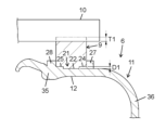
- FIG. 1 is a perspective view of a blower according to a first embodiment of the present disclosure.
- FIG. 2 is a schematic cross-sectional view of the blower.
- FIG. 3 is a plan view of the second case of the fan case of the blower.
- FIG. 4 is a perspective view of the second case.
- FIG. 5 is a partially enlarged view of FIG. 3, showing a part of the attachment surface of the second case.
- FIG. 6 is a cross-sectional view showing a first state of the configuration in which the seal sponge is attached to the attachment surface of the same.
- FIG. 7 is a cross-sectional view showing a second state of the configuration in which the seal sponge is attached to the attachment surface of the same.
- FIG. 8 is a cross-sectional view of the first recess of the attachment surface of the same.
- FIG. 9 is a cross-sectional view of the second recess of the attachment surface of the same.
- FIG. 10 is a cross-sectional view of the third recess of the attachment surface of the same.
- FIG. 11 is a cross-sectional view of the fourth recess of the attachment surface of the same.
- FIG. 12 is a partial plan view of an inner surface of a second cover in the second embodiment of the present disclosure.
- FIG. 13 is a plan view of the second case of the fan case of the blower according to the third embodiment of the present disclosure.
- FIG. 14 is a cross-sectional view of the fifth recess of the attachment surface of the second case.
- FIG. 15 is a cross-sectional view of the sixth recess of the attachment surface of the same.
- FIG. 16 is a cross-sectional view of the seventh recess on the attachment surface of the same.
- FIG. 17 is a partial plan view of an inner surface of a second cover in the fourth embodiment of the present disclosure.
- FIG. 18 is a schematic diagram of a vehicle according to a fifth embodiment of the present disclosure.
- Fig. 1 is a perspective view of a blower 1 according to a first embodiment of the present disclosure.
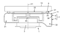
- Fig. 2 is a schematic cross-sectional view of the blower 1.
- the blower 1 is, for example, a blower for cooling a battery in a vehicle.
- the blower 1 is a centrifugal fan blower.
- the blower 1 mainly has a fan case 2, a motor 3, and a centrifugal fan 4.
- the motor 3 and the centrifugal fan 4 are housed inside the fan case 2.
- the fan case 2 has an intake port 33 for drawing in outside air, an exhaust port 34 for discharging air toward the outside space, and a circular passage 31 and an exhaust passage 32 which are passages connecting the intake port 33 and the exhaust port 34.
- the intake port 33 is circular.
- the exhaust port 34 is rectangular. Air is drawn into the fan case 2 from the intake port 33, flows through the circular passage 31 and the exhaust passage 32 in that order, and is discharged from the exhaust port 34.
- the motor 3 is, for example, an inner rotor type brushless motor.
- the motor 3 is not limited to a brushless motor.
- the motor 3 may be another type of DC motor or AC motor.
- a brushed motor may also be used as the motor 3.
- the direction in which the axis X1 (see FIG. 2) of the rotating shaft 44 of the motor 3 extends is defined as the axial direction.
- the direction extending from the axis X1 is defined as the radial direction, and the direction going around the axis X1 is defined as the circumferential direction.
- the centrifugal fan 4 is a member in which a plurality of blade members are connected at a predetermined interval between mutually opposing annular members.
- the centrifugal fan 4 is connected to the rotating shaft 44 of the motor 3 so as to rotate integrally therewith.
- the blade members can be formed of either metal or resin.
- the centrifugal fan 4 rotates at a predetermined speed in the circumferential direction in response to the rotation of the motor 3, thereby drawing in outside air from the intake port 33 and compressing it.
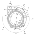
- FIG. 3 is a plan view of the second case 6 of the fan case 2 of the blower 1 according to the first embodiment of the present disclosure.
- the compressed air moves through the circulating passage 31 in the order of arrows A1, A2, A3, and A4 in FIG. 3.
- the compressed air further moves through the exhaust passage 32 in the direction of arrow B1 in FIG. 3.
- the compressed air is finally discharged from the exhaust port 34.
- the discharged air is supplied to the battery from the exhaust port 34.
- the fan case 2 is a hollow member formed by molding resin.
- the fan case 2 has an air intake port 33 on the top surface.
- the fan case 2 houses the motor 3 and the centrifugal fan 4, and is substantially cylindrical in shape.
- the fan case 2 has an upper wall, a side wall, and a lower wall of the circulating passage 31 and the exhaust passage 32.
- the fan case 2 is configured to cover the centrifugal fan 4. Due to this configuration, the circulating passage 31 and the exhaust passage 32 are formed inside the fan case 2 so as to follow the outer periphery of the centrifugal fan 4.
- the circulating passage 31 has a spiral shape so as to surround the outer periphery of the centrifugal fan 4.
- the exhaust passage 32 is linear.
- the circulating passage 31 is an internal space for guiding air sucked in from the intake port 33 to the exhaust passage 32 when the centrifugal fan 4 rotates due to the rotational motion transmitted from the motor 3.
- the area of a cross section including the axis X1 in the circulating passage 31 gradually increases toward the exhaust passage 32.
- the air intake 33 is, for example, an intake port for air into the vehicle cabin.
- the air intake 33 is formed on the axial end face (the end face at the top of the figure) of the substantially cylindrical fan case 2 that faces the vehicle cabin.
- the air intake 33 is an opening with a diameter that is approximately the same as or slightly smaller than that of the centrifugal fan 4.
- the air intake 33 is connected to the vehicle cabin via the duct 10 (see Figure 2).
- the duct 10 is a member for effectively directing air to the blower 1.
- the exhaust port 34 opens in a direction that is in a twisted relationship with the axial direction. In other words, air that is sucked in from a direction along the axis X1 of the centrifugal fan 4 toward the fan case 2 is exhausted in a direction that is in a twisted relationship with the axis X1.
- the fan case 2 is made of a resin such as polypropylene. As shown in Figures 1 and 2, the fan case 2 is divided into a lower first case 5 and an upper second case 6.
- the outer side of the first case 5 has a plurality of protrusions 41 spaced at predetermined intervals in the circumferential direction.
- the side of the second case 6 has a plurality of hooks 42 spaced at predetermined intervals in the circumferential direction.
- the first case 5 and second case 6 are connected by the plurality of hooks 42 engaging with the plurality of protrusions 41, respectively.
- the intake port 33 is formed in the second case 6.
- the exhaust port 34 is formed by fitting the second case 6 and the first case 5 together.
- the motor 3 and centrifugal fan 4 are fixed to the first case 5.
- the second case 6 has a case body 11.
- the case body 11 is a member that constitutes the upper part of the circulating passage 31 and the exhaust passage 32.
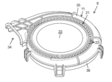
- the second case 6 mainly has an annular flat surface portion 35 and a side surface portion 36.
- the annular flat surface portion 35 is a roughly flat annular portion that constitutes the intake port 33.
- the side surface portion 36 is a roughly cylindrical portion that extends axially from the outer periphery of the annular flat surface portion 35.
- FIG. 3 is a plan view of the second case 6 of the fan case 2 of the blower 1 according to the first embodiment of the present disclosure.
- Fig. 4 is a perspective view of the second case 6.
- an annular adhesive section 21 attachment section
- annular seal sponge 9 sealing member
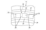
- a plurality of individual recesses 22 are formed in the adhesive section 21 and are arranged at equal intervals in the direction in which the adhesive section 21 extends.
- Each individual recess 22 is generally rectangular in plan view.
- the attachment portion 21 further has, as an attachment surface, an outer peripheral plane 24 (first plane) on the outer peripheral side of the plurality of individual recesses 22, an inner peripheral plane 25 (second plane) on the inner peripheral side of the individual recesses 22, and a plurality of radial planes 26 extending between adjacent individual recesses 22 and connecting the outer peripheral plane 24 and the inner peripheral plane 25. Due to the above configuration and the plurality of individual recesses 22, the attachment portion 21 has a lattice shape in a plan view. An outer peripheral protrusion 27 extending in the axial direction is provided on the outer peripheral side of the outer peripheral plane 24. An inner peripheral protrusion 28 extending in the axial direction is provided on the inner peripheral side of the inner peripheral plane 25.
- the depth of the multiple individual recesses 22 gradually increases in the direction in which the circular passage 31 extends, from the side farther from the exhaust passage 32 to the side closer to the exhaust passage 32.
- the distance (shortest distance) between the bottom surface of each individual recess 22 and the inner surface 12 of the circular passage 31 is the same. This is because, as a prerequisite structure, the thickness of the part of the attachment portion 21 where the individual recesses 22 are not formed (for example, the distance between the outer peripheral plane 24 and the inner peripheral plane 25 and the inner surface 12 of the case body 11) decreases from the side farther from the exhaust passage 32 to the side closer to the exhaust passage 32.
- the distance (first distance, first thickness) between the bottom surface of the individual recess 22 (first location, first part) farther from the exhaust passage 32 than the circumferential center point C1 (FIG. 3) of the circular passage 31 and the inner side surface 12 of the circular passage 31 is the same as the distance (second distance, second thickness) between the bottom surface of the individual recess 22 (second location, second part) closer to the exhaust passage 32 than the circumferential center point C1 of the circular passage 31 and the inner side surface 12 of the circular passage 31.
- “same” means that the difference in thickness is only to the extent that no significant warping (deformation) occurs due to the difference in shrinkage between the parts with different thicknesses when the resin constituting the case body 11 is cooled and hardened after molding.
- the case where the thinnest part is 2 mm and the thickest part is 3 mm (1.5 times) is also included in “same”.
- the thickness of the thickest part is less than twice the thickness of the thinnest part.
- the former is in the range of 1.0 to 1.6 times the latter.
- each individual recess 22 may be flat, curved, or a combination of multiple surface shapes. It is preferable that the distance between the bottom surface of each individual recess 22 and the corresponding inner surface 12 is uniform across the entire bottom surface of each individual recess 22. For example, if the corresponding inner surface 12 is curved, it is preferable that the bottom surface of the individual recess 22 is curved to correspond to the inner surface 12.
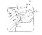
- FIG. 6 is a cross-sectional view showing a first state of a configuration in which the seal sponge 9 is attached to the attachment surface of the second case 6 of the fan case 2 of the blower 1 according to the first embodiment of the present disclosure.
- Fig. 7 is a cross-sectional view showing a second state of a configuration in which the seal sponge 9 is attached to the attachment surface of the second case 6 of the fan case 2 of the blower 1 according to the first embodiment of the present disclosure.
- the seal sponge 9 is attached to the attachment portion 21. More specifically, the seal sponge 9 is attached to the outer peripheral flat surface 24, the inner peripheral flat surface 25, and the multiple radial flat surfaces 26 (see FIG. 5) between the outer peripheral protrusion 27 and the inner peripheral protrusion 28 via adhesive. In this state, a gap is secured between the seal sponge 9 and the bottom surface of the individual recess 22.
- the seal sponge 9 may be structured so as not to be in close contact with the bottom surface of the individual recess 22. In that case, it is preferable to set the ratio of the area of the individual recess 22 to the attachment portion 21 to an appropriate value. For example, the ratio of the area of the individual recess 22 to the attachment portion 21 is 40 to 60%.
- FIG. 8 is a cross-sectional view of the first recess 221 on the attachment surface of the second case 6 of the fan case 2 of the blower 1 according to the first embodiment of the present disclosure.
- FIG. 9 is a cross-sectional view of the second recess 222 on the attachment surface of the same.
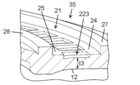
- FIG. 10 is a cross-sectional view of the third recess 223 on the attachment surface of the same.
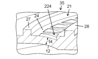
- FIG. 11 is a cross-sectional view of the fourth recess 224 on the attachment surface of the same.
- the first recess 221 and the second recess 222 in the following description are each an example of a first location on the side farther from the exhaust passage 32 than the circumferential center point C1 (see FIG. 3) of the circular passage 31.
- the third recess 223 and the fourth recess 224 are each an example of a second location on the side closer to the exhaust passage 32 than the circumferential center point C1 (see FIG. 3) of the circular passage 31.
- FIG. 8 is a cross-sectional view of the start point of the circular passage 31 in FIG. 3 or its surroundings (cross-sectional view taken along the line I-I in FIG. 3), showing the first recess 221.
- the inner peripheral portion of the first recess 221 has a curved surface shape that follows the curved surface shape of the inner surface 12.
- the inner peripheral portion of the first recess 221 has a thickness t11 (shortest distance between the bottom surface of the recess and the inner surface 12).
- the outer peripheral portion of the first recess 221 has a flat shape.
- the outer peripheral portion of the first recess 221 has a thickness t12 (shortest distance between the bottom surface of the recess and the inner surface 12).
- FIG. 9 is a cross-sectional view of the first midpoint of the circular passage 31 in FIG. 3 (cross-sectional view taken along the line II-II in FIG. 3), showing the second recess 222.
- the second recess 222 is located closer to the start point of the circular passage 31 than the circumferential center point C1.
- the second recess 222 has a planar shape that follows the planar shape of the inner surface 12, and has a thickness t2 (the shortest distance between the bottom surface of the recess and the inner surface 12).
- the thickness t2 is less than or equal to the thicknesses t11 and t12.
- FIG. 10 is a cross-sectional view of the second midpoint of the circular passage 31 in FIG. 3 (cross-sectional view taken along the III-III arrow in FIG. 3), showing the third recess 223.
- the third recess 223 is located closer to the end point of the circular passage 31 than the circumferential center point C1.
- the third recess 223 has a curved surface shape that follows the curved surface shape of the inner surface 12, and has a thickness t3 (the shortest distance between the bottom surface of the recess and the inner surface 12).
- the thickness t3 is less than or equal to the thickness t2.
- FIG. 11 is a cross-sectional view (cross-sectional view taken along the arrows IV-IV in FIG. 3) of the end point of the circular passage 31 or its vicinity in FIG. 3, showing the fourth recess 224.
- the fourth recess 224 has a curved surface shape that follows the curved surface shape of the inner surface 12, and has a thickness t4 (the shortest distance between the bottom surface of the recess and the inner surface 12). Thickness t4 is equal to or less than thickness t3.
- the individual recesses 22 are disposed at equal intervals in the direction in which the circular passage 31 extends. However, the intervals may be different. For example, the intervals may become wider or narrower as the exhaust passage 32 is approached.
- the multiple individual recesses 22 are rectangular in plan view. However, the multiple individual recesses 22 may have other shapes in plan view. Furthermore, multiple types of individual recesses with planar shapes may be provided on one attachment surface.
- the bottom surfaces of the multiple individual recesses 22 all have the same area. However, the areas may be different from each other. For example, the bottom surfaces of the multiple individual recesses 22 may have an area that becomes wider or narrower as they approach the exhaust passage 32.
- the individual recesses 22 are separated from one another. However, the individual recesses 22 may be connected to one another by a connecting recess along the direction in which the circular passage 31 extends. In that case, the width of the connecting recess is not particularly limited.
- the multiple individual recesses 22 are formed around the entire circumference of the attachment portion 21. However, the multiple individual recesses 22 may be formed around only a portion of the entire circumference of the attachment portion 21.
- the recess formed in the attachment portion may be a single recess along the extension direction of the attachment portion.
- the radial plane 26 is connected to the outer circumferential plane 24 and the inner circumferential plane 25. However, the radial plane 26 may be separated from both. In other words, a recess may be provided between the radial plane 26 and the outer circumferential plane 24 and the inner circumferential plane 25.
- the radial plane 26 extends in the radial direction. However, the radial plane 26 may extend obliquely so as to follow the flow of gas from the centrifugal fan 4 toward the circulation passage 31.
- the inner surface 12 of the case body 11 has a smoothly extending shape.
- the inner surface 12 of the case body 11 may be provided with a groove.
- Figure 12 is a partial plan view of the inner surface of the second cover in the second embodiment of the present disclosure.
- the basic configuration and basic operation of the second embodiment are the same as those of the first embodiment. Therefore, the following description will focus on the differences.
- FIG. 12 shows a part of the inner surface 12A of the annular flat portion 35A of the case body 11A. Specifically, the attachment portion 21A, the plurality of individual recesses 22A, the outer peripheral flat surface 24A, and the inner peripheral flat surface 25A on the opposite side are shown by dashed lines.
- a groove portion 15A is provided on the inner surface 12A of the case body 11A.
- the groove portion 15A has a first portion 151A formed at a position corresponding to the outer peripheral plane 24A (between the outer peripheral edge and inner peripheral edge of the outer peripheral plane 24A in a plan view) and a second portion 152A formed at a position corresponding to the multiple individual recesses 22A (between both circumferential edges of the radial plane 26A in a plan view).
- the first and second parts 151A and 152A of the groove 15A are gradually deeper in the direction in which the circular passage extends, from the side farther from the exhaust passage to the side closer to the exhaust passage.
- the distance between the bottom surfaces of the first and second parts 151A and 152A of the groove 15A and the outer circumferential plane 24A and radial plane 26A of the attachment part 21A is the same. This is because, as a prerequisite structure, the thickness of the part of the attachment part 21A where the individual recesses 22A are not formed (the distance between the outer circumferential plane 24A and inner circumferential plane 25A and the inner surface 12A of the case body 11A) becomes smaller from the side farther from the exhaust passage to the side closer to the exhaust passage.
- the groove portion 15A makes the thickness of the case body 11A in the attachment portion 21A other than the individual recess 22A equal to or close to the thickness of the case body 11A in the individual recess 22A. As a result, the area of the portion where the distance between the attachment portion 21A and the inner surface 12A of the circular passage is substantially the same can be made sufficiently large.
- the shape and position of the groove are not particularly limited.
- the grooves may be formed at positions corresponding to both the outer circumferential plane and the inner circumferential plane.
- the grooves do not have to be formed at positions corresponding to the radial planes.
- the grooves may be formed only at positions corresponding to the radial planes.
- the attachment portion is provided with a recess.
- the attachment portion may have a planar shape without a recess.
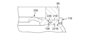
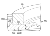
- Figure 13 is a plan view of the second case 6B of the fan case 2 of the blower 1 according to the third embodiment of the present disclosure.
- Figure 14 is a cross-sectional view of the fifth recess of the attachment surface 22B of the second case 6B.
- Figure 15 is a cross-sectional view of the sixth recess of the attachment surface of the second case 6B.
- Figure 16 is a cross-sectional view of the seventh recess of the attachment surface 22B of the second case 6B.
- the basic configuration and basic operation of the third embodiment are the same as those of the first embodiment. Therefore, the basic configuration and basic operation of the third embodiment will be described below, focusing on the differences.
- the adhesive portion 21B has a flat adhesive surface 22B.
- the seal sponge 9B is adhered to the adhesive surface 22B.
- the portion of the inner surface 12B of the case body 11B that corresponds to the pasting surface 22B has a flat or curved surface that extends smoothly along the direction in which the circular passage 31B extends.
- the distance between the pasting surface 22B and the portion of the inner surface 12B that corresponds to the pasting portion 21B of the case body 11B is the same over the entire circumference in the direction in which the circular passage 31B extends.
- "same” means that when the resin that constitutes the case body 11B is cooled and hardened after molding, the difference in thickness is only to the extent that no significant warping (deformation) occurs due to the difference in shrinkage between the portions with different thicknesses.
- the case where the thinnest part is 2 mm and the thickest part is 3 mm (1.5 times) is also included in "same" in this embodiment.
- the thickness of the thickest part is less than twice the thickness of the thinnest part.
- the former is in the range of 1.0 to 1.6 times the latter.
- the distance (first distance) between the attachment surface 22B (first location) on the side farther from the exhaust passage 32B than the circumferential center point C1 (see FIG. 13) of the circular passage 31B and the inner surface 12B is the same as the distance (second distance) between the attachment surface 22B (second location) on the side closer to the exhaust passage 32 than the circumferential center point C1 (see FIG. 13) and the inner surface 12B.
- the relationship between the adhesive portion 21B and the inner surface 12B will be specifically described with reference to Figures 14, 15, and 16.
- the first portion 221B and the second portion 222B in the following description are an example of a first location that is farther from the exhaust passage 32B than the circumferential center point C1 of the circular passage 31B.
- the third portion 223B is an example of a second location that is closer to the exhaust passage 32B than the circumferential center point C1 of the circular passage 31B.
- FIG. 14 is a cross-sectional view of the first midpoint of the circular passage 31B in FIG. 13 (cross-sectional view taken along the V-V arrow in FIG. 13), showing the first portion 221B.
- the first portion 221B is located closer to the starting point of the circular passage 31B than the circumferential center point C1.
- the inner surface 12B has a flat portion on the radially inner side and a curved surface portion on the radially outer side.
- the inner surface 12B has a radially inner thickness t51 (shortest distance between the attachment surface 22B and the inner surface 12B) and a radially outer thickness t52 (shortest distance between the attachment surface 22B and the inner surface 12B).
- FIG. 15 is a cross-sectional view of the second midpoint of the circular passage 31B in FIG. 13 (cross-sectional view taken along the line VI-VI in FIG. 13), showing the second portion 222B.
- the second portion 222B is located closer to the starting point of the circular passage 31B than the circumferential center point C1.
- the inner surface 12B has a flat portion on the radially inner side and a curved surface portion on the radially outer side.
- the inner surface 12B has a radially inner thickness t61 (shortest distance between the attachment surface 22B and the inner surface 12B) and a radially outer thickness t62 (shortest distance between the attachment surface 22B and the inner surface 12B). Thicknesses t61 and t62 are less than or equal to thicknesses t51 and t52, respectively.
- FIG. 16 is a cross-sectional view (cross-sectional view taken along the line VII-VII in FIG. 13) of the end point of the circular passage 31B or its vicinity, showing the third portion 223B.
- the third portion 223B has a planar shape that conforms to the planar shape of the inner surface 12B.
- the third portion 223B has a thickness t7 (the shortest distance between the attachment surface 22B and the inner surface 12B). The thickness t7 is less than or equal to the thicknesses t61 and t62.
- the inner surface of the case body 11B corresponding to the attachment portion has a flat shape or a smoothly curved surface shape, but may be provided with a recess.
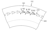
- Figure 17 is a partial plan view of the inner surface 12C of the second cover in the fourth embodiment of the present disclosure.
- the basic configuration and basic operation of the fourth embodiment are the same as those of the third embodiment. Therefore, the following description will focus on the differences.
- the attachment portion 21C has a flat attachment surface 22C.
- a plurality of individual inner recesses 15C are formed aligned in the direction in which the attachment surface 22C extends.
- the plurality of individual inner recesses 15C correspond to the attachment surface 22C and are located near the outer circumferential corners of the inner surface 12C.
- Each of the plurality of individual inner recesses 15C has a shape whose width increases as it approaches the exhaust passage side along the circumferential direction. In this way, the width of the individual inner recess 15C increases from upstream to downstream in the air flow direction. Therefore, within the individual inner recess 15C, the air moves downstream while expanding in the width direction. Therefore, the ventilation resistance caused by the individual inner recess 15C does not increase.
- the depth of the multiple individual inner recesses 15C gradually increases in the circumferential direction from the side farther from the exhaust passage to the side closer to the exhaust passage.
- the distance between the bottom surface of each individual inner recess 15C and the attachment surface 22C is substantially the same. This is because the thickness of the portion of the attachment portion 21C where the individual inner recesses 15C are not formed decreases in the circumferential direction from the side farther from the exhaust passage to the side closer to the exhaust passage.
- the distance (first distance, first thickness) between the bottom surface of the individual inner recess 15C (first location, first part) farther from the exhaust passage than the circumferential center point of the circulation passage and the attachment surface 22C may be longer than the distance (second distance, second thickness) between the bottom surface of the individual inner recess 15C (second location, second part) closer to the exhaust passage than the circumferential center point of the air passage and the inner surface 12C.
- the former is preferably less than twice the latter. It is more preferable that the former is in the range of 1.0 to 1.6 times the latter.
- the planar shape of the individual inner recesses 15C is not particularly limited.
- the number, position, and spacing of the individual inner recesses 15C are not particularly limited.
- each individual inner recess 15C may be flat, curved, or a combination of multiple surface shapes.
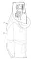
- Fig. 18 is a schematic diagram of a vehicle 51 according to a fifth embodiment of the present disclosure.
- the vehicle 51 includes a blower 1, a battery 52 (object to be cooled), a control device 53, a cable 54, a cable 56, and a vehicle body 55 (main vehicle body).
- vehicle 51 is a four-wheel hybrid vehicle in which an engine and a driving battery 52 are mounted on a vehicle body 55.
- Vehicle 51 is not limited to a hybrid vehicle, and may also be an electric vehicle.
- the vehicle 51 on which the blower 1 is mounted is not limited to a four-wheeled vehicle, but may be, for example, a vehicle (automobile) such as a two-wheeled vehicle or a three-wheeled vehicle.
- vehicle automobile
- the object to be cooled may be a part other than the battery 52.
- the vehicle body 55 is provided with a blower 1, a battery 52, a control device 53, a cable 54, and a cable 56.
- the battery 52 is, for example, a lithium ion battery, a nickel-metal hydride battery, or the like.
- the battery 52 supplies power to the blower 1, the drive motor for propelling the vehicle 51, and the like.
- the control device 53 is electrically connected to the blower 1 via a cable 54.
- the control device 53 controls the blower 1. More specifically, the control device 53 is electrically connected to the motor drive circuit of the blower 1 via a cable 54.
- the control device 53 controls the battery 52 via a cable 56. More specifically, the control device 53 controls the power supply from the battery 52 to the blower 1 and the drive motor, etc.
- the blower 1 used in the vehicle 51 functions as a cooling fan system to suppress a rise in temperature of the battery 52.
- the control device 53 controls the blower 1 to blow air from the blower 1 to the battery 52, air is sent from the blower 1 to the battery 52. This air-cools the battery 52 and suppresses a rise in temperature of the battery 52.
- the blower (1) includes a case body (11, 11A, 11B, 11C) that constitutes a part of the circulation passage (31, 31B) and the exhaust passage (32, 32B).
- the case body (11, 11A, 11B, 11C) has an annular mounting portion (21, 21A, 21B, 21C) on the outer surface of the case body (11, 11A, 11B, 11C) that is provided with a mounting surface (24, 25, 26, 24A, 25A, 26A, 22B, 22C) to which a seal member (9, 9B) is attached.
- the mounting portion (21, 21A, 21B, 21C) has, in the circumferential direction in which the circular passage (31, 31B) extends, a first location that is farther from the exhaust passage (32, 32B) than the circumferential center point (C1) of the circular passage (31, 31B), and a second location that is closer to the exhaust passage (32, 32B) than the circumferential center point (C1) of the circular passage (31, 31B).
- the first thickness of the case body (11, 11A, 11B, 11C) at the first location is equal to or greater than the second thickness of the case body (11, 11A, 11B, 11C) at the second location.
- the first thickness of the case body (11, 11A, 11B, 11C) at the first location is equal to or greater than the second thickness of the case body (11, 11A, 11B, 11C) at the second location. Therefore, the difference in thickness of the case body (11, 11A, 11B, 11C) at the mounting portion (21, 21A, 21B, 21C) in the direction in which the circulating passage (31) extends is small. Therefore, when the resin constituting the case body (11, 11A, 11B, 11C) cools and hardens after molding, warping (deformation) caused by differential shrinkage in the portions with different thicknesses is less likely to occur.
- blower (1) is obtained in which the mounting surfaces (24, 25, 26, 24A, 25A, 26A, 22B, 22C) of the case body (11, 11A, 11B, 11C) to which the sealing members (9, 9B) are attached have a high degree of flatness.
- the case body (11, 11A) has recesses (22, 22A) formed at different circumferential positions on the outer surface of the mounting portion (21, 21A).
- the recesses (22, 22A) have a first portion as a first location and a second portion as a second location.
- the first distance between the bottom surface of the first portion as the first thickness and the inner surface (12, 12A) of the case body (11, 11A) is equal to or greater than the second distance between the bottom surface of the second portion as the second thickness and the inner surface (12, 12A) of the case body (11, 11A).
- the first distance between the bottom surface of the first portion and the inner surface (12, 12A) of the case body (11, 11A) is equal to or greater than the second distance between the bottom surface of the second portion and the inner surface (12, 12A) of the case body (11, 11A). Therefore, the difference in thickness of the case body (11, 11A) in the recess (22, 22A) of the mounting portion (21, 21A) in the direction in which the circulating passage (31) extends is small.
- the recess (22, 22A) has a plurality of individual recesses (22, 22A) formed in a line in the circumferential direction at the mounting portion.
- the plurality of individual recesses (22, 22A) has a first individual recess (22, 22A) as a first portion and a second individual recess (22, 22A) as a second portion.
- the first distance between the bottom surface of the first individual recess (22, 22A) and the inner side surface (12, 12A) of the case body (11, 11A) is greater than or equal to the second distance between the bottom surface of the second individual recess (22, 22A) and the inner side surface (12, 12A) of the case body (11, 11A). Therefore, in the direction in which the circular passage (31) extends, the difference in thickness of the case body (11, 11A) at the first individual recess (22, 22A) and the second individual recess (22, 22A) is small.
- the mounting portion has a first plane (24, 24A) provided on the outer periphery of the plurality of individual recesses (22, 22A) and a second plane (25, 25A) provided on the inner periphery of the plurality of individual recesses (22, 22A).
- first plane (24, 24A) and the second plane (25, 25A) function as mounting surfaces (24, 25, 26, 24A, 25A, 26A) to which the seal member (9) is attached.
- the distance between the first plane (24, 24A) and the second plane (25, 25A) and the inner surface (12, 12A) of the case body (11, 11A) becomes shorter as they approach the exhaust passage (32) along the circumferential direction.
- the depth of the multiple individual recesses (22, 22A) becomes smaller as they approach the exhaust passage (32) along the circumferential direction.
- the difference in thickness of the case body (11, 11A) between the first individual recess (22, 22A) and the second individual recess (22, 22A) is small in the direction in which the circular passage (31) extends. Therefore, when the resin constituting the case body (11, 11A) is cooled and hardened after molding, warping (deformation) caused by the difference in shrinkage of the parts with different thicknesses is unlikely to occur. As a result, a blower (1) is obtained in which the mounting surface (24, 25, 26, 24A, 25A, 26A) of the case body (11, 11A) to which the seal member (9) is attached has a high flatness.
- the case body (11A) has a groove portion (15A) provided on the inner surface (12A) at a position corresponding to at least one of the first plane (24A) and the second plane (25A) in a plan view.
- the thickness of the case body (11A) can be reduced in the first plane (24A) and the second plane (25A).
- the mounting surface (22B) has a planar shape.
- the distance between the mounting surface (22B) and the inner surface (12B) of the case body (11B) corresponding to the mounting surface (22B) is the same at the first location and the second location.
- the thickness of the case body (11B) of the mounting portion (21B) is the same at the first and second locations in the direction in which the circulation passage (31B) extends. Therefore, when the resin constituting the case body (11B) is cooled and hardened after molding, warping (deformation) caused by differential shrinkage of the portions with different thicknesses is unlikely to occur. As a result, a blower (1) is obtained in which the mounting surface (22B) of the case body (11B) to which the seal member (9B) is attached has a high degree of flatness.
- the case body (11C) further has an inner recess (15C) formed at different circumferential positions on the inner surface (12C) of the case body (11C) corresponding to the mounting surface (22C).
- the mounting surface (22C) has a planar shape.
- the inner recess (15C) has a first portion as a first location and a second portion as a second location. The first distance between the bottom surface of the first portion as the first thickness and the mounting surface (22C) is equal to or greater than the second distance between the bottom surface of the second portion as the second thickness and the mounting surface (22C).
- the first distance between the mounting surface of the first part and the inner side surface (12C) of the case body (11C) is equal to or greater than the second distance between the mounting surface (22C) of the second part and the inner side surface (12C) of the case body (11C). Therefore, the difference in thickness of the case body (11C) in the inner recess (15C) corresponding to the mounting part (21C) in the direction in which the circulation passage (31) extends is small. Therefore, when the resin constituting the case body (11C) is cooled and hardened after molding, warping (deformation) caused by the difference in shrinkage of the parts with different thicknesses is unlikely to occur. As a result, a blower (1) is obtained in which the mounting surface (22C) of the case body (11C) to which the seal member is attached has a high flatness.
- the inner recess (15C) has a plurality of individual inner recesses (15C) formed in a line in the circumferential direction.
- the plurality of individual inner recesses (15C) have a first individual inner recess (15C) as a first portion and a second individual inner recess (15C) as a second portion.
- the first distance between the bottom surface of the first individual inner recess (15C) and the mounting surface (22C) is equal to or greater than the second distance between the bottom surface of the second individual inner recess (15C) and the mounting surface (22C). Therefore, the difference in thickness of the case body (11C) in the circumferential direction between the first individual inner recess (15C) and the second individual inner recess (15C) is small. Therefore, when the resin constituting the case body (11C) is cooled and hardened after molding, warping (deformation) caused by the difference in shrinkage of the parts with different thicknesses is unlikely to occur. As a result, a blower (1) is obtained in which the mounting surface (22C) of the case body (11C) to which the seal member is attached has a high flatness.
- the distance between the mounting surface (22C) and the inner surface (12C) of the case body (11C) becomes shorter as it approaches the exhaust passage along the circumferential direction.
- the depth of the multiple individual inner recesses (15C) becomes smaller as it approaches the exhaust passage along the circumferential direction.
- the thickness of the case body (11C) in the first individual inner recess (15C) and the second individual inner recess (15C) is uniform in the circumferential direction. Therefore, when the resin constituting the case body (11C) is cooled and hardened after molding, warping (deformation) caused by differential shrinkage in the parts with different thicknesses is unlikely to occur. As a result, a blower (1) is obtained in which the mounting surface of the case body (11C) to which the seal member is attached has a high degree of flatness.
- each of the multiple individual inner recesses (15C) has a shape whose width increases circumferentially toward the exhaust passage side.
- the width of the individual inner recess (15C) increases from upstream to downstream in the air flow direction, so that the air moves downstream while expanding in the width direction inside the individual inner recess (15C). Therefore, the ventilation resistance caused by the individual inner recess (15C) does not increase.
- the moving body (51) includes the above-mentioned blower (1), an object to be cooled (52) that is cooled by the blower (1), and a moving body (55) on which the blower (1) and the object to be cooled (52) are mounted.
- Blower 2 Fan case 3: Motor 4: Centrifugal fan 9, 9B: Seal sponge (sealing member) 11, 11A, 11B, 11C: Case body 12, 12A, 12B, 12C: Inner surface 15A: Groove portion 15C: Individual inner recess 21, 21A, 21B, 21C: Attachment portion (mounting portion) 22, 22A: individual recesses 22B, 22C: attachment surfaces (mounting surfaces) 24, 24A: Outer peripheral plane (first plane) 25, 25A: Inner peripheral plane (second plane) 31, 31B: circulation passage 32, 32B: exhaust passage 33: intake port 34: exhaust port 51: vehicle (moving body) 52: Battery (object to be cooled) 55: Vehicle body (mobile body) X1: Shaft center
Landscapes
- Engineering & Computer Science (AREA)
- Mechanical Engineering (AREA)
- General Engineering & Computer Science (AREA)
- Chemical & Material Sciences (AREA)
- Combustion & Propulsion (AREA)
- Transportation (AREA)
- Structures Of Non-Positive Displacement Pumps (AREA)
Abstract
La présente invention concerne une soufflante comprenant un corps de carter constituant un passage de circulation et une partie d'un passage d'évacuation. Le corps de carter présente, sur une surface externe du corps de carter, une partie de fixation annulaire pourvue d'une surface de fixation à laquelle un élément d'étanchéité est fixé. La partie de fixation présente, dans une direction circonférentielle dans laquelle s'étend le passage de circulation, une première section sur un côté plus éloigné du passage d'évacuation qu'un point central circonférentiel du passage de circulation et une seconde section sur un côté plus proche du passage d'évacuation que le point central circonférentiel du passage de circulation. Une première épaisseur du corps de carter au niveau de la première section est égale ou supérieure à une seconde épaisseur du corps de carter au niveau de la seconde section.
Priority Applications (2)
| Application Number | Priority Date | Filing Date | Title |
|---|---|---|---|
| JP2025527600A JPWO2024257562A1 (fr) | 2023-06-16 | 2024-05-21 | |
| CN202480036927.2A CN121219499A (zh) | 2023-06-16 | 2024-05-21 | 风机和移动体 |
Applications Claiming Priority (2)
| Application Number | Priority Date | Filing Date | Title |
|---|---|---|---|
| JP2023-099509 | 2023-06-16 | ||
| JP2023099509 | 2023-06-16 |
Publications (1)
| Publication Number | Publication Date |
|---|---|
| WO2024257562A1 true WO2024257562A1 (fr) | 2024-12-19 |
Family
ID=93851818
Family Applications (1)
| Application Number | Title | Priority Date | Filing Date |
|---|---|---|---|
| PCT/JP2024/018689 Ceased WO2024257562A1 (fr) | 2023-06-16 | 2024-05-21 | Soufflante et corps mobile |
Country Status (3)
| Country | Link |
|---|---|
| JP (1) | JPWO2024257562A1 (fr) |
| CN (1) | CN121219499A (fr) |
| WO (1) | WO2024257562A1 (fr) |
Citations (2)
| Publication number | Priority date | Publication date | Assignee | Title |
|---|---|---|---|---|
| JP2019065739A (ja) * | 2017-09-29 | 2019-04-25 | 新明和工業株式会社 | ポンプ |
| JP2020204274A (ja) * | 2019-06-14 | 2020-12-24 | 株式会社マキタ | ブロワ |
-
2024
- 2024-05-21 JP JP2025527600A patent/JPWO2024257562A1/ja active Pending
- 2024-05-21 CN CN202480036927.2A patent/CN121219499A/zh active Pending
- 2024-05-21 WO PCT/JP2024/018689 patent/WO2024257562A1/fr not_active Ceased
Patent Citations (2)
| Publication number | Priority date | Publication date | Assignee | Title |
|---|---|---|---|---|
| JP2019065739A (ja) * | 2017-09-29 | 2019-04-25 | 新明和工業株式会社 | ポンプ |
| JP2020204274A (ja) * | 2019-06-14 | 2020-12-24 | 株式会社マキタ | ブロワ |
Also Published As
| Publication number | Publication date |
|---|---|
| JPWO2024257562A1 (fr) | 2024-12-19 |
| CN121219499A (zh) | 2025-12-26 |
Similar Documents
| Publication | Publication Date | Title |
|---|---|---|
| KR101799123B1 (ko) | 원심 송풍기 조립체 | |
| KR101119749B1 (ko) | 차량용 전기 팬 | |
| JP4479799B2 (ja) | 車両用交流発電機 | |
| JP6931774B2 (ja) | 温度調和システム、車両 | |
| JP6751854B2 (ja) | 温度調和ユニット、温度調和システム、車両 | |
| JP6652077B2 (ja) | 遠心送風機 | |
| US20150118037A1 (en) | Centrifugal fan | |
| JP6818443B2 (ja) | 電動送風機及びそれを備えた電気掃除機 | |
| US11332052B2 (en) | Centrifugal blower device | |
| US20190390676A1 (en) | Centrifugal blower device | |
| US20200127345A2 (en) | Temperature conditioning unit, temperature conditioning system, and vehicle | |
| CN107431392A (zh) | 转子组件和包括该转子组件的马达 | |
| WO2024257562A1 (fr) | Soufflante et corps mobile | |
| US11448077B2 (en) | Method for manufacturing turbo fan | |
| JP2019077439A (ja) | ブロワモータ組立体 | |
| CN118922632A (zh) | 风机及移动体 | |
| WO2026048383A1 (fr) | Souffleur | |
| CN213817433U (zh) | 电机及燃料电池发动机系统 | |
| JP6690603B2 (ja) | 遠心送風機 | |
| JP7760897B2 (ja) | 送風機 | |
| JP5724380B2 (ja) | 軸流ファン | |
| CN121969839A (zh) | 风扇壳体、风机及移动体 | |
| WO2025211087A1 (fr) | Souffleur et corps mobile | |
| WO2023188813A1 (fr) | Soufflante et corps mobile | |
| CN121605248A (zh) | 风机和移动体 |
Legal Events
| Date | Code | Title | Description |
|---|---|---|---|
| 121 | Ep: the epo has been informed by wipo that ep was designated in this application |
Ref document number: 24823184 Country of ref document: EP Kind code of ref document: A1 |
|
| ENP | Entry into the national phase |
Ref document number: 2025527600 Country of ref document: JP Kind code of ref document: A |
|
| WWE | Wipo information: entry into national phase |
Ref document number: 2025527600 Country of ref document: JP |
|
| NENP | Non-entry into the national phase |
Ref country code: DE |