WO2024257611A1 - Procédé et appareil de nettoyage du plastique - Google Patents
Procédé et appareil de nettoyage du plastique Download PDFInfo
- Publication number
- WO2024257611A1 WO2024257611A1 PCT/JP2024/019639 JP2024019639W WO2024257611A1 WO 2024257611 A1 WO2024257611 A1 WO 2024257611A1 JP 2024019639 W JP2024019639 W JP 2024019639W WO 2024257611 A1 WO2024257611 A1 WO 2024257611A1
- Authority
- WO
- WIPO (PCT)
- Prior art keywords
- temperature
- superheated steam
- low
- plastic
- treatment area
- Prior art date
- Legal status (The legal status is an assumption and is not a legal conclusion. Google has not performed a legal analysis and makes no representation as to the accuracy of the status listed.)
- Ceased
Links
Images
Classifications
-
- B—PERFORMING OPERATIONS; TRANSPORTING
- B08—CLEANING
- B08B—CLEANING IN GENERAL; PREVENTION OF FOULING IN GENERAL
- B08B3/00—Cleaning by methods involving the use or presence of liquid or steam
- B08B3/04—Cleaning involving contact with liquid
-
- B—PERFORMING OPERATIONS; TRANSPORTING
- B29—WORKING OF PLASTICS; WORKING OF SUBSTANCES IN A PLASTIC STATE IN GENERAL
- B29B—PREPARATION OR PRETREATMENT OF THE MATERIAL TO BE SHAPED; MAKING GRANULES OR PREFORMS; RECOVERY OF PLASTICS OR OTHER CONSTITUENTS OF WASTE MATERIAL CONTAINING PLASTICS
- B29B13/00—Conditioning or physical treatment of the material to be shaped
- B29B13/02—Conditioning or physical treatment of the material to be shaped by heating
-
- B—PERFORMING OPERATIONS; TRANSPORTING
- B29—WORKING OF PLASTICS; WORKING OF SUBSTANCES IN A PLASTIC STATE IN GENERAL
- B29B—PREPARATION OR PRETREATMENT OF THE MATERIAL TO BE SHAPED; MAKING GRANULES OR PREFORMS; RECOVERY OF PLASTICS OR OTHER CONSTITUENTS OF WASTE MATERIAL CONTAINING PLASTICS
- B29B17/00—Recovery of plastics or other constituents of waste material containing plastics
- B29B17/02—Separating plastics from other materials
-
- Y—GENERAL TAGGING OF NEW TECHNOLOGICAL DEVELOPMENTS; GENERAL TAGGING OF CROSS-SECTIONAL TECHNOLOGIES SPANNING OVER SEVERAL SECTIONS OF THE IPC; TECHNICAL SUBJECTS COVERED BY FORMER USPC CROSS-REFERENCE ART COLLECTIONS [XRACs] AND DIGESTS
- Y02—TECHNOLOGIES OR APPLICATIONS FOR MITIGATION OR ADAPTATION AGAINST CLIMATE CHANGE
- Y02W—CLIMATE CHANGE MITIGATION TECHNOLOGIES RELATED TO WASTEWATER TREATMENT OR WASTE MANAGEMENT
- Y02W30/00—Technologies for solid waste management
- Y02W30/50—Reuse, recycling or recovery technologies
- Y02W30/62—Plastics recycling; Rubber recycling
Definitions
- the present invention relates to a method and apparatus for cleaning plastics, and more particularly to a method and apparatus for cleaning plastics to remove impurities from used plastics.
- a common method for removing impurities from plastics is washing with an organic solvent or water.
- Patent Document 1 discloses a method of removing impurities by contacting polyethylene with an organic solvent and purifying the solution.
- Patent Document 2 discloses a method of crushing packaging materials (plastic films) and then chemically cleaning them with an acid or alkali for recycling, and
- Patent Document 3 discloses a method of separating foreign matter and plastics by washing with water.
- Patent Document 4 the applicant has proposed a method for removing impurities from plastics by washing with superheated steam as a washing medium.
- Patent Document 4 uses water, so it does not have a negative impact on the environment, does not require large-scale exhaust equipment or waste liquid treatment equipment, and can cleanly remove not only oily stains such as grease and oils adhering to the plastic surface, but also impurities such as oily stains (i.e., sorption components) that have soaked into the plastic, just as when an organic solvent is used as a cleaning medium.
- oily stains i.e., sorption components
- the object of the present invention is therefore to provide a method and apparatus for removing contaminants from plastics using superheated steam treatment, which effectively removes contaminants in a significantly reduced treatment time.
- the inventors discovered that in order to effectively remove contaminants from used plastics by superheated steam treatment and obtain plastics with almost no odor in a short time, it is effective to remove the plastics that have been kept at high temperatures for cleaning from the superheated steam treatment area not immediately, but by allowing the temperature to drop appropriately while undergoing superheated steam treatment, and then removing them from the superheated steam treatment area, thus completing the present invention.
- a superheated steam treatment area maintained at a temperature of 100° C. or more is provided in a conveying path, and plastics are introduced into the superheated steam treatment area through which superheated steam flows to perform cleaning of the plastics
- the superheated steam treatment area is formed of a high-temperature treatment area to which relatively high-temperature superheated steam is supplied and a low-temperature treatment area to which relatively low-temperature superheated steam is supplied, the high-temperature treatment area and the low-temperature treatment area are continuous with each other,
- the plastic is continuously transferred from the high temperature processing area to the low temperature processing area for superheated steam processing; continuously removing treated plastic from said low temperature treatment zone; A method for cleaning plastics is provided.
- the following means are preferably used: (1) Superheated steam having a temperature of 100°C to 150°C is supplied to the low-temperature treatment area, and superheated steam having a temperature 20°C or more higher than that of the superheated steam supplied to the low-temperature treatment area is supplied to the high-temperature treatment area. (2) The time during which the plastic passes through the high-temperature treatment area is set to be longer than the time during which the plastic passes through the low-temperature treatment area. (3) The plastic to be processed is used plastic. (4) The oxygen concentration in the superheated steam treatment area is adjusted to 5% or less throughout the area.
- a plastic washing apparatus including a superheated steam treatment chamber to which a steam supply pipe and a steam exhaust pipe are connected and which is maintained at a temperature of 100° C. or higher, and a plastic transport member passing through the superheated steam treatment chamber, the superheated steam treatment chamber is provided with a high-temperature treatment region located on an inlet side of the plastic and supplied with relatively high-temperature superheated steam, and a low-temperature treatment region located on an outlet side of the plastic and supplied with relatively low-temperature superheated steam, the steam supply pipe is connected to each of the high temperature processing area and the low temperature processing area;
- a plastic cleaning device is provided, comprising: In such a plastic washing device, (5) The steam exhaust pipe is connected to each of the high temperature treatment area and the low temperature treatment area; is preferred.
- the plastic washing method of the present invention involves supplying the plastic to be treated (specifically used plastic) to a superheated steam treatment area maintained at a temperature of 100°C or higher and washing with superheated steam, but this treatment area is divided into a high-temperature treatment area and a low-temperature treatment area, and the plastic is passed continuously from the high-temperature treatment area to the low-temperature treatment area and continuously removed.
- the plastic following the superheated steam treatment in the high-temperature treatment area, the plastic is continuously removed while the treatment temperature is lowered in the presence of superheated steam, eliminating the need for a post-process dehydration process, and effectively washing in a very short time, not only effectively removing contaminants but also obtaining plastic that has almost no odor.
- This type of washing process effectively removes foreign matter, and not only removes contaminants, but also preferably washes away (deodorizes) odorous components resulting from the decomposition of the plastic or contaminants.
- the treatment chamber was divided into a high-temperature treatment area and a low-temperature treatment area, and superheated steam set at a temperature of 220° C. was supplied to the high-temperature treatment area, and superheated steam set at a temperature of 150° C. was supplied to the low-temperature treatment area, and cleaning with superheated steam was performed continuously.
- the conveying speed of the plastic was set so that the treatment time (passage time) in the high-temperature treatment area was 5 minutes, and the treatment time (passage time) in the low-temperature treatment area was 2 minutes, and the total treatment time in the treatment chamber was quite short at 7 minutes.
- the inventors have concluded that while the cleaning time at high temperatures is important when using superheated steam treatment, if plastic kept at a relatively high temperature is kept in an atmosphere with a high oxygen content for a long period of time, the deterioration of the plastic will progress, and the amount of pollutants (acids and aldehydes) that cause odors will increase, causing the generation of odors.
- the present invention has succeeded in sufficiently removing pollutants in a short period of time and effectively suppressing the generation of odors by continuously performing superheated steam treatment while preventing the plastic from being kept in the atmosphere at a temperature above a certain level.
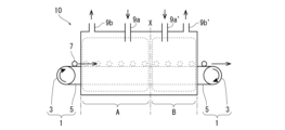
- FIG. 1 is a schematic diagram showing a cleaning device for carrying out the method of the present invention.
- the cleaning apparatus designated by the numeral 10
- the cleaning apparatus has a high-temperature treatment chamber A (high-temperature treatment area) and a low-temperature treatment chamber B (low-temperature treatment area) arranged side by side in series, and a continuous conveying device 1 is provided so as to pass through the interior of these chambers.
- the continuous conveying device 1 is composed of a pair of conveying rollers 3, 3 and a conveying belt 5 stretched between the conveying rollers 3, 3.
- the conveying belt 5 is driven by the rotation of the conveying rollers 3, 3, and the plastic 7 to be treated is continuously conveyed from the high-temperature treatment chamber A to the low-temperature treatment chamber B, from which it is removed to the outside.
- the high-temperature processing chamber A and the low-temperature processing chamber B are connected to each other, and there is no partition between them.
- Each processing chamber is provided with its own steam supply pipe (9a and 9a') and steam exhaust pipe (9b and 9b'). That is, in the high-temperature processing chamber A, high-temperature steam is supplied from the steam supply pipe 9a and exhausted from the steam exhaust pipe 9b, and in the low-temperature processing chamber B, low-temperature steam is supplied from the steam supply pipe 9a' and exhausted from the steam exhaust pipe 9b'.
- the superheated steam introduced creates a high-temperature atmosphere in the high-temperature processing chamber A, and a low-temperature atmosphere compared to the high-temperature processing chamber A is created in the low-temperature processing chamber B.
- the high-temperature treatment chamber A is provided with a steam exhaust pipe 9b
- the low-temperature treatment chamber B is provided with a steam exhaust pipe 9b', but depending on the overall capacity of the cleaning device 10 and the steam supply speed from the steam supply pipe 9a or 9a', it is possible to use only one steam exhaust pipe.
- a steam exhaust pipe 9b for exhausting high-temperature superheated steam in the high-temperature treatment chamber A and a steam exhaust pipe 9b' for exhausting low-temperature superheated steam in the low-temperature treatment chamber B with dedicated steam exhaust pipes provided for each, as shown in FIG. 1.
- inert gas such as nitrogen can be appropriately supplied and discharged from these steam supply pipes 9a and 9a', so that the atmosphere in the high-temperature processing chamber A and the low-temperature processing chamber B can be replaced with the inert gas, and the oxygen concentration in the chambers can be further reduced.
- the supply of the inert gas is not limited to the above-mentioned method as long as it is possible to reduce the oxygen concentration in the high-temperature processing chamber A and the low-temperature processing chamber B, and a method of supplying the inert gas from a source other than the steam supply pipes 9a and 9a' may also be used.
- cleaning equipment examples include a series of high-temperature treatment chambers (high-temperature treatment zones) with different temperature settings, each of which is provided with its own steam supply pipe (and even a steam exhaust pipe), allowing each chamber to be set to an arbitrary temperature depending on the plastic being treated.
- the cleaning device 10 is also constructed so that the atmosphere in the high-temperature processing chamber A and the low-temperature processing chamber B is maintained at 100°C or higher, condensation of the supplied superheated steam is prevented (particularly at the inlet and outlet sides of the device), and the temperature sprayed onto the plastic 7 in each processing chamber A and B is maintained at the set temperature by a heater or the like.
- ⁇ Cleaning medium> impurities are removed from plastics using the above-mentioned cleaning device 10, and superheated steam (i.e., water) is used as the cleaning medium.
- superheated steam i.e., water
- This superheated steam has a lower dielectric constant due to heating compared to water at 100° C. or less, and for example, superheated steam with a relative dielectric constant of 60 or less, preferably 40 or less, more preferably 25 or less, and even more preferably 10 or less is used.
- the relative dielectric constant of water at room temperature is significantly higher than that of organic solvents, making it a unique polar solvent, which has poor affinity (oil repellency) for organic components (oil components such as fats and oils), making it difficult to remove dirt.
- the relative dielectric constant decreases as the temperature increases. As can be understood from this, cleaning is performed with water (superheated steam) that is in a state close to that of an organic solvent, with the dielectric constant being reduced by heating.
- Patent Document 4 also provides a detailed explanation of the method of measuring the relative dielectric constant, but when water is heated to about 200°C, its relative dielectric constant becomes about 35, which is close to the relative dielectric constant of methanol at room temperature, and when heated to about 300°C, its relative dielectric constant becomes about 20, which is close to the relative dielectric constant of acetone at room temperature, and when heated further and near the critical point, it becomes the same as non-polar organic solvents such as chloroform and ethyl ether.
- the superheated steam used as the cleaning medium is in a state close to an organic solvent due to its non-polarity caused by its low dielectric constant, and furthermore, due to this low dielectric constant, the water becomes high-temperature steam at over 100° C.
- the polymer chains that make up the plastic loosen, and the low-dielectric water easily penetrates into the plastic.
- water vapor which has been made to have a low dielectric constant and become nearly non-polar like an organic solvent, and which has been heated to a high temperature to reduce the dielectric constant, as a cleaning medium, impurities adhering to the surface of plastics and impurities sorbed within the plastics can be effectively removed.
- the water used as the cleaning medium may be in a state called superheated steam, subcritical water, or supercritical water, for example, in high-temperature treatment chamber A, due to heating to reduce the dielectric constant as described above.
- the plastic to be cleaned is a so-called used plastic, and any plastic can be used as long as it is not decomposed by cleaning with heated steam as described above.
- preferred examples include olefin resins that are widely recycled by sorting and recovery, such as low-density polyethylene, linear low-density polyethylene, medium or high-density polyethylene, polypropylene, poly-1-butene, and poly-4-methyl-1-pentene.
- ⁇ -olefins such as ethylene, propylene, 1-butene, and 4-methyl-1-pentene
- cyclic olefin copolymers disclosed in JP-A-2007-284066 and the like can also be suitably used.
- Such olefin resins are chemically very stable, and when cleaning with high-temperature water with a low dielectric constant, not only is there little risk of hydrolysis, but they can also be easily recovered.
- EVOH ethylene-vinyl alcohol copolymer
- the effects of the present invention are maximized.
- EVOH is a resin that is widely used in the field of packaging materials as a gas barrier resin, and prevents oxidative deterioration of packaged materials by blocking the permeation of oxygen.
- it is susceptible to thermal degradation, and has the property of generating odorous components such as acids and aldehydes due to thermal degradation.
- the treatment method of the present invention the generation of odorous components can be effectively prevented even when EVOH is contained.
- the used plastics are collected from waste plastic molded products (such as containers and lids), appropriately separated from other molded products of different materials, and subjected to crushing, washing, separation by specific gravity, etc. to remove as much foreign matter as possible.
- waste plastic molded products such as containers and lids
- specific gravity, etc. to remove as much foreign matter as possible.
- the plastics it is preferable for the plastics to be crushed into a flake or granular form, and in particular those with a mesh diameter of 10 mm or less, more preferably 8 mm or less, and even more preferably 6 mm or less.
- the above-mentioned cleaning of plastics i.e., the cleaning process for removing contaminants, is carried out using the cleaning apparatus 10 described above. That is, by continuously driving the conveyor device 1 (conveyor belt 5), used plastics 7 are continuously introduced into the cleaning device 10, and the plastics are cleaned by spraying superheated steam onto them in the cleaning device 10, and the cleaned plastics are continuously removed from the cleaning device 10.
- the present invention makes it possible to obtain plastics from which contaminants have been removed in an extremely short period of time.
- the above-mentioned cleaning device 10 is divided into a high-temperature processing chamber A and a low-temperature processing chamber B. While the plastic 7 is being transported, a cleaning process using relatively high-temperature superheated steam is carried out in the high-temperature processing chamber A, and then a cleaning process using relatively low-temperature superheated steam is carried out in the low-temperature processing chamber B.
- the high-temperature treatment chamber A is structured to be kept at a high temperature using a heater or the like, while the low-temperature treatment chamber B is structured so that the interior atmosphere is cooled using a heat exchanger, and the temperature of the water vapor supplied can be made lower than that of the high-temperature treatment chamber A.
- low-temperature treatment chamber B is supplied with water vapor at a relatively lower temperature than that in high-temperature treatment chamber A, for example, water vapor at a temperature preferably between 100°C and 150°C, more preferably between 100°C and 135°C, and even more preferably between 100°C and 120°C, and is set so as to be sprayed onto the plastics 7 being continuously transported.
- water vapor at a temperature preferably between 100°C and 150°C, more preferably between 100°C and 135°C, and even more preferably between 100°C and 120°C
- the high-temperature treatment chamber A is set up so that superheated steam at a higher temperature is sprayed compared to the low-temperature treatment chamber B.
- superheated steam at a temperature at least 20°C higher, preferably 35°C or higher, and more preferably 50°C higher than the superheated steam supplied in the low-temperature treatment chamber B is supplied and sprayed onto the plastic 7 being continuously transported.
- sorbed substances such as oil stains adhering to the plastic surface and oil stains that have penetrated into the plastic can be effectively cleaned and removed.
- the high-temperature treatment chamber A since the high-temperature treatment chamber A is connected to the low-temperature treatment chamber B, there is an overall temperature distribution in the high-temperature treatment chamber A and the low-temperature treatment chamber B, with the atmospheric temperature at the outlet side of the low-temperature treatment chamber B being the lowest.
- the maximum temperature in the high-temperature treatment chamber A is set to 300°C or less, more preferably 260°C or less, and even more preferably 230°C or less. If this maximum temperature is higher than necessary, it may cause decomposition of the plastic 7, or it may become difficult to adjust the temperature in the next low-temperature treatment chamber B, making it difficult to complete the treatment in a short time.
- the low-temperature treatment chamber B which is provided adjacent to the high-temperature treatment chamber A, is supplied with water vapor at a lower temperature than the superheated steam supplied to the high-temperature treatment chamber A to perform the cleaning process, thereby effectively suppressing deterioration of the plastic 7.
- Example 12 of Patent Document 4 if there is no low-temperature treatment chamber B and the temperature of the treatment chamber A is lowered and cooled after the treatment in the high-temperature treatment chamber A, this becomes a so-called batch process rather than a continuous process, and cooling takes a long time, making it impossible to complete cleaning in a short time.
- the plastics 7 maintained at a high temperature are cleaned with superheated steam without coming into direct contact with the atmosphere having a high oxygen concentration. That is, if the plastics 7 were to come into contact with the atmosphere at a high temperature, it would deteriorate, and as shown in the experimental example described later, aldehyde would be produced, which would result in the generation of an odor. Therefore, in this low-temperature treatment chamber B, cleaning is performed with superheated steam, so the temperature at the outlet side must be maintained at at least 100° C. to prevent condensation of the superheated steam.
- the temperature at the outlet side is excessively high, the temperature of the plastics 7 cleaned in the high-temperature treatment chamber A will not be sufficiently reduced, and the plastics 7 treated with superheated steam will come into contact with the atmosphere at a high temperature, causing deterioration of the plastics 7, increasing the amount of aldehyde generated, and causing a strong odor.
- the high-temperature processing chamber A and the low-temperature processing chamber B are not separated by a partition or the like, but are connected to each other. For this reason, the two chambers A and B cannot be strictly distinguished from each other.
- the temperature gradient from the high-temperature processing chamber A to the low-temperature processing chamber B can be confirmed by measuring the temperature of the upper surface of the conveyor belt 5 running through the processing chambers A and B or its vicinity with a thermocouple or the like in advance laboratory tests, thereby confirming the ambient temperature (or temperature gradient) in the high-temperature processing chamber A where the processing with high-temperature superheated steam is performed, and the ambient temperature (or temperature gradient) in the low-temperature processing chamber B where the processing with low-temperature superheated steam is performed.
- the residence time in the high-temperature treatment chamber A long and the residence time in the low-temperature treatment chamber B short.
- the low-temperature treatment chamber B is an area whose main purpose is to suppress the deterioration of the plastic 7 rather than to remove contaminants, and there is no need to set the residence time long, as long as the residence time required to lower the temperature to a certain level is ensured.
- the residence time in the high-temperature treatment chamber A can be set long by positioning the steam supply pipe 9a for supplying high-temperature superheated steam closer to the outlet side than the center.
- the residence time in the high-temperature treatment chamber A can be set long by providing multiple high-temperature treatment chambers (high-temperature treatment areas) in succession and providing a dedicated steam supply pipe (and even a steam exhaust pipe) for each high-temperature treatment chamber.
- the residence time in the two chambers A and B can be set arbitrarily by installing a transport device in each of the high-temperature treatment chambers A and B and connecting them.
- the temperature gradient in the high-temperature processing chamber A and the low-temperature processing chamber B can be measured by the method described above, and the position where the temperature drops sharply can be set as the boundary line X between the high-temperature processing chamber A and the low-temperature processing chamber B.
- the residence time in the high-temperature processing chamber A and the residence time of the continuously transported plastic 7 in the low-temperature processing chamber B can be set.
- the residence time in the high-temperature processing chamber A (the passage time of the plastic 7) set in this way is longer than the residence time in the low-temperature processing chamber B.
- the residence time in the low-temperature processing chamber B is about 95 to 10% of the residence time in the high-temperature processing chamber A.
- the oxygen concentration is adjusted to 5% or less throughout, more preferably 3% or less, and further preferably 1% or less.
- the amount of superheated steam supplied (kg/h) to the high-temperature treatment chamber A and the low-temperature treatment chamber B to which the superheated steam is supplied a state in which the oxygen concentration is maintained low can be obtained.
- Plastics from which impurities (organic impurities such as oily stains from grease and oils) have been removed in a shorter time by the above-mentioned cleaning process are less likely to deteriorate and produce less odor, so they can be pelletized by melt extrusion, either alone or after being molten and mixed with virgin plastic using an extruder or the like, and then molded again as recycled plastic, and reused as packaging containers, etc.
- the plastic after cleaning can also be reused as a recycled product as is.
- the present invention does not require large-scale exhaust equipment or waste liquid treatment equipment, and can remove contaminants from used plastics in an extremely short time, just as when organic solvents are used, making it an extremely useful technology for recycling plastics.
- Sample to be cleaned Sample A was used as the plastic to be cleaned. This was flakes obtained by crushing a high-density polyethylene bottle after filling it with edible oil. The sample was left untreated and the aldehydes were measured in the same manner as in the experimental example described below. As a reference, the same measurement was also carried out on sample A0, which was flakes obtained by crushing a high-density polyethylene bottle not filled with oil.
- the SPME fiber was measured using a gas chromatography mass spectrometer (Agilent Technology GC/MS GC-7890A, MSD-5975C) to desorb the components adsorbed on the SPME fiber, and the components separated by gas chromatography were detected and analyzed by mass spectrometry to qualitatively and quantitatively identify the impurity components.
- a gas chromatography mass spectrometer Alignment Technology GC/MS GC-7890A, MSD-5975C
- Example 1 The above-mentioned sample A was used as the plastic to be cleaned. Sample A was placed on the conveying device 1 (conveyor belt 5) and treated by passing through the high-temperature treatment chamber A filled with superheated steam at 220°C for 5 minutes, and then passed through the low-temperature treatment chamber B filled with superheated steam at 150°C for 2 minutes, and sample A was removed from the cleaning device 10. In this case, the treatment time was 7 minutes. In addition, the water supply rate of superheated steam was 20 kg/h for a sample charge of 10 g. The obtained sample was pretreated by solid-phase microextraction and aldehydes were measured by gas chromatography mass spectrometry.
- the position of the boundary line X between the high-temperature processing chamber A and the low-temperature processing chamber B was determined by measuring the temperature distribution on the conveyor belt 5 and determining the portion where the temperature suddenly drops from 220° C. to 150° C.
- the evaluation results are shown in Table 1.
- Example 2 The same treatment and measurement as in Experimental Example 1 were carried out, except that the temperature of the superheated steam in the low-temperature treatment chamber B was set to 100° C. The evaluation results are shown in Table 1. The boundary line X between the high temperature processing chamber A and the low temperature processing chamber B was almost the same as in the first experimental example.
- Example 3 The same treatment and measurement as in Experimental Example 1 were carried out, except that the superheated steam temperature in the high-temperature treatment chamber A was 200° C. and the superheated steam temperature in the low-temperature treatment chamber B was 100° C. In this example, too, the boundary line X between the high-temperature treatment chamber A and the low-temperature treatment chamber B was almost the same as in Experimental Example 1. The evaluation results are shown in Table 1.
- Example 4 The same treatment and measurement as in Experimental Example 1 were carried out, except that the temperature of the superheated steam in the low-temperature treatment chamber B was set to 100° C. and the treatment was carried out by passing the superheated steam through the low-temperature treatment chamber B for 10 minutes. The evaluation results are shown in Table 1.
- Example 5 The same processing and measurement as in Experimental Example 1 were carried out, except that the low-temperature processing chamber B was not used (the entire cleaning apparatus 10 was filled with superheated steam at 220° C.) and the sample A was immediately removed from the cleaning apparatus 10. In other words, the entire cleaning apparatus 10 was the high-temperature processing apparatus A, and the low-temperature processing chamber B was not provided.
- the evaluation results are shown in Table 1.
- Example 6 The same treatment and measurement as in Experimental Example 3 were carried out, except that the entire cleaning device 10 was filled with superheated steam at 200° C., sample A was passed through it for 5 minutes, and then immediately removed. In this example, the entire cleaning device 10 was the high-temperature treatment device A, and no low-temperature treatment chamber B was provided. The evaluation results are shown in Table 1.
- Example 7 The entire cleaning apparatus 10 was filled with superheated steam at 150° C., and the sample A was passed through it for 7 minutes and then removed. Except for this, the same treatment and measurement as in Experimental Example 1 were carried out. In other words, the entire cleaning apparatus 10 was the high-temperature treatment apparatus A, and the low-temperature treatment chamber B was not provided. The evaluation results are shown in Table 1.
- Example 8 The cleaning device 10 was entirely filled with superheated steam at 100° C., and sample A was passed through it for 7 minutes and then removed, but the same treatment and measurement as in Experimental Example 7 were carried out. That is, in this example, the entire cleaning apparatus 10 is a high-temperature processing apparatus A, and a low-temperature processing chamber B is not provided. The evaluation results are shown in Table 1.
- Example 9 (Batch type) Sample A was placed in a batch-type reactor filled with superheated steam at 240° C. and treated for 5 minutes. After completion of the treatment, the reactor was opened at the treatment temperature and sample A was taken out. In this case, the treatment time was 5 minutes. The amount of superheated steam supplied was 20 kg/h for a sample charge of 10 g. The obtained sample was subjected to measurement of aldehydes by gas chromatography mass spectrometry in the same manner as in Experimental Example 1. The evaluation results are shown in Table 1.
- Example 10 (Batch type) Sample A was placed in a batch-type reactor filled with superheated steam at 240° C., treated for 5 minutes, and then cooled to 150° C. in a superheated steam atmosphere before opening the reactor and removing the sample. The measurements were carried out in the same manner as in Experimental Example 9. The evaluation results are shown in Table 1. At this time, it took 20 minutes to lower the temperature to 150° C., and the total treatment time was 25 minutes. In Table 1, the low-temperature treatment chamber B is described as cooling chamber B.
Landscapes
- Engineering & Computer Science (AREA)
- Mechanical Engineering (AREA)
- Environmental & Geological Engineering (AREA)
- Physics & Mathematics (AREA)
- Thermal Sciences (AREA)
- Treatments Of Macromolecular Shaped Articles (AREA)
- Separation, Recovery Or Treatment Of Waste Materials Containing Plastics (AREA)
- Glass Compositions (AREA)
- Cleaning By Liquid Or Steam (AREA)
- Processing And Handling Of Plastics And Other Materials For Molding In General (AREA)
Abstract
La présente invention concerne un ^procédé de nettoyage du plastique dans lequel une zone de traitement à la vapeur surchauffée maintenue à une température supérieure ou égale à 100 °C est disposée sur un trajet de transport, et un plastique 7 est introduit dans la zone de traitement à la vapeur surchauffée à travers laquelle de la vapeur surchauffée est amenée à s'écouler et un traitement à la vapeur surchauffée est effectué, ledit procédé de nettoyage du plastique étant caractérisé en ce que la zone de traitement à la vapeur surchauffée est formée à partir d'une zone de traitement à haute température A dans laquelle est fournie de la vapeur surchauffée à une température relativement élevée et une zone de traitement à basse température B dans laquelle est fournie de la vapeur surchauffée à une température relativement basse ; la zone de traitement à haute température A et la zone de traitement à basse température B sont contiguës, et le traitement à la vapeur surchauffée est réalisé avec le plastique 7 transporté en continu de la zone de traitement à haute température A à la zone de traitement à basse température B ; et le plastique 7 traité est retiré en continu de la zone de traitement à basse température B.
Applications Claiming Priority (2)
| Application Number | Priority Date | Filing Date | Title |
|---|---|---|---|
| JP2023-096245 | 2023-06-12 | ||
| JP2023096245A JP2024177868A (ja) | 2023-06-12 | 2023-06-12 | プラスチックの洗浄方法及び装置 |
Publications (1)
| Publication Number | Publication Date |
|---|---|
| WO2024257611A1 true WO2024257611A1 (fr) | 2024-12-19 |
Family
ID=93851857
Family Applications (1)
| Application Number | Title | Priority Date | Filing Date |
|---|---|---|---|
| PCT/JP2024/019639 Ceased WO2024257611A1 (fr) | 2023-06-12 | 2024-05-29 | Procédé et appareil de nettoyage du plastique |
Country Status (3)
| Country | Link |
|---|---|
| JP (1) | JP2024177868A (fr) |
| TW (1) | TW202504741A (fr) |
| WO (1) | WO2024257611A1 (fr) |
Citations (11)
| Publication number | Priority date | Publication date | Assignee | Title |
|---|---|---|---|---|
| JPH03137977A (ja) * | 1989-10-24 | 1991-06-12 | Shinichi Mori | 洗浄装置 |
| US5120370A (en) * | 1991-04-01 | 1992-06-09 | Shinichi Mori | Cleaning process |
| JPH0655114A (ja) * | 1992-06-09 | 1994-03-01 | Kanken Techno Kk | 洗浄装置および洗浄方法 |
| JP2003251627A (ja) * | 2002-03-07 | 2003-09-09 | Jfe Steel Kk | 廃棄プラスチックを素材リサイクルするための洗浄方法及び装置 |
| JP2006272621A (ja) * | 2005-03-28 | 2006-10-12 | Kurimoto Ltd | 廃棄プラスチック洗浄脱水装置 |
| JP2010142779A (ja) * | 2008-12-22 | 2010-07-01 | Nippon Handa Kk | 長尺物を脱脂洗浄する洗浄装置及び洗浄方法 |
| JP2012167213A (ja) * | 2011-02-15 | 2012-09-06 | Astec Irie Co Ltd | 塗膜付きプラスチック部品の処理方法 |
| JP2018141201A (ja) * | 2017-02-28 | 2018-09-13 | モリテックスチール株式会社 | 過熱水蒸気による油分除去システム及び過熱水蒸気発生装置 |
| JP2019103969A (ja) * | 2017-12-12 | 2019-06-27 | 株式会社ショウワ | 洗浄乾燥装置 |
| WO2022124015A1 (fr) * | 2020-12-07 | 2022-06-16 | 東洋製罐グループホールディングス株式会社 | Procédé pour l'élimination d'impuretés d'une matière plastique |
| JP2023148861A (ja) * | 2022-03-30 | 2023-10-13 | リンテック株式会社 | コーティング層の除去方法及びコーティング層の除去装置 |
-
2023
- 2023-06-12 JP JP2023096245A patent/JP2024177868A/ja active Pending
-
2024
- 2024-05-29 WO PCT/JP2024/019639 patent/WO2024257611A1/fr not_active Ceased
- 2024-05-30 TW TW113119952A patent/TW202504741A/zh unknown
Patent Citations (11)
| Publication number | Priority date | Publication date | Assignee | Title |
|---|---|---|---|---|
| JPH03137977A (ja) * | 1989-10-24 | 1991-06-12 | Shinichi Mori | 洗浄装置 |
| US5120370A (en) * | 1991-04-01 | 1992-06-09 | Shinichi Mori | Cleaning process |
| JPH0655114A (ja) * | 1992-06-09 | 1994-03-01 | Kanken Techno Kk | 洗浄装置および洗浄方法 |
| JP2003251627A (ja) * | 2002-03-07 | 2003-09-09 | Jfe Steel Kk | 廃棄プラスチックを素材リサイクルするための洗浄方法及び装置 |
| JP2006272621A (ja) * | 2005-03-28 | 2006-10-12 | Kurimoto Ltd | 廃棄プラスチック洗浄脱水装置 |
| JP2010142779A (ja) * | 2008-12-22 | 2010-07-01 | Nippon Handa Kk | 長尺物を脱脂洗浄する洗浄装置及び洗浄方法 |
| JP2012167213A (ja) * | 2011-02-15 | 2012-09-06 | Astec Irie Co Ltd | 塗膜付きプラスチック部品の処理方法 |
| JP2018141201A (ja) * | 2017-02-28 | 2018-09-13 | モリテックスチール株式会社 | 過熱水蒸気による油分除去システム及び過熱水蒸気発生装置 |
| JP2019103969A (ja) * | 2017-12-12 | 2019-06-27 | 株式会社ショウワ | 洗浄乾燥装置 |
| WO2022124015A1 (fr) * | 2020-12-07 | 2022-06-16 | 東洋製罐グループホールディングス株式会社 | Procédé pour l'élimination d'impuretés d'une matière plastique |
| JP2023148861A (ja) * | 2022-03-30 | 2023-10-13 | リンテック株式会社 | コーティング層の除去方法及びコーティング層の除去装置 |
Also Published As
| Publication number | Publication date |
|---|---|
| JP2024177868A (ja) | 2024-12-24 |
| TW202504741A (zh) | 2025-02-01 |
Similar Documents
| Publication | Publication Date | Title |
|---|---|---|
| Roosen et al. | Deodorization of post-consumer plastic waste fractions: A comparison of different washing media | |
| US11028248B2 (en) | System and process for recycling contaminated polyolefins | |
| KR102205183B1 (ko) | 폴리올레핀 재순환물의 생성 방법 | |
| TWI544999B (zh) | A method for treating and detoxifying, and a device for carrying out the method | |
| KR100351785B1 (ko) | 중합체로부터오염물을제거하는방법 | |
| TW202110977A (zh) | 醛含量降低方法及具有低醛含量之經回收的聚烯烴 | |
| US9550132B2 (en) | Removing volatile compounds from polymer granules by vapour distillation | |
| KR102327161B1 (ko) | 플라즈마 배기가스 정화 | |
| KR20020055580A (ko) | 폐기된 페트 용기로부터 식품 접촉 등급의 폴리에틸렌테레프탈레이트 수지를 제조하는 방법 | |
| EP3981486A1 (fr) | Procédé et système pour élimination d'odeurs dans des plastiques recyclés | |
| CN114058073A (zh) | 使用滚筒对滚筒加工步骤的基于溶剂的回收利用 | |
| CN111688055B (zh) | 用于回收聚烯烃的方法 | |
| WO2021047545A1 (fr) | Procédé d'élimination d'impuretés polymères basé sur une distillation à la vapeur | |
| JP2022036914A (ja) | 統合されたドラム乾燥と押出しによるポリマー溶液からの溶媒除去方法 | |
| JP2024177868A (ja) | プラスチックの洗浄方法及び装置 | |
| JP2012061392A (ja) | アルミニウム屑の処理方法 | |
| US12558817B2 (en) | Method of removing impurities from plastic | |
| US20070249804A1 (en) | Preparation of Ultrapure Polymeric Articles | |
| Wulandari et al. | VOC removal from automotive waste by supercritical CO2 extraction | |
| CN112454725A (zh) | 一种聚乙烯气体脱除装置 | |
| CN114230693A (zh) | 一种连续脱除乙丙橡胶中voc、降低气味等级的方法 | |
| EP4235070A2 (fr) | Installation de séchage de matériau polymère granulaire | |
| JP2019527644A (ja) | 熱媒液を用いた照射済み材料固体の熱処理 | |
| US6288131B1 (en) | Inline solid state polymerization of pet flakes for manufacturing plastic strap | |
| TH2201006304A (th) | กระบวนการกำจัดกลิ่นของเม็ดโพลีโอเลฟินรีไซเคิล |
Legal Events
| Date | Code | Title | Description |
|---|---|---|---|
| 121 | Ep: the epo has been informed by wipo that ep was designated in this application |
Ref document number: 24823231 Country of ref document: EP Kind code of ref document: A1 |
|
| NENP | Non-entry into the national phase |
Ref country code: DE |