WO2024257699A1 - Pale d'éolienne - Google Patents
Pale d'éolienne Download PDFInfo
- Publication number
- WO2024257699A1 WO2024257699A1 PCT/JP2024/020825 JP2024020825W WO2024257699A1 WO 2024257699 A1 WO2024257699 A1 WO 2024257699A1 JP 2024020825 W JP2024020825 W JP 2024020825W WO 2024257699 A1 WO2024257699 A1 WO 2024257699A1
- Authority
- WO
- WIPO (PCT)
- Prior art keywords
- wind turbine
- turbine blade
- spar cap
- blade
- composite material
- Prior art date
- Legal status (The legal status is an assumption and is not a legal conclusion. Google has not performed a legal analysis and makes no representation as to the accuracy of the status listed.)
- Ceased
Links
Images
Classifications
-
- F—MECHANICAL ENGINEERING; LIGHTING; HEATING; WEAPONS; BLASTING
- F03—MACHINES OR ENGINES FOR LIQUIDS; WIND, SPRING, OR WEIGHT MOTORS; PRODUCING MECHANICAL POWER OR A REACTIVE PROPULSIVE THRUST, NOT OTHERWISE PROVIDED FOR
- F03D—WIND MOTORS
- F03D1/00—Wind motors with rotation axis substantially parallel to the air flow entering the rotor
- F03D1/06—Rotors
-
- Y—GENERAL TAGGING OF NEW TECHNOLOGICAL DEVELOPMENTS; GENERAL TAGGING OF CROSS-SECTIONAL TECHNOLOGIES SPANNING OVER SEVERAL SECTIONS OF THE IPC; TECHNICAL SUBJECTS COVERED BY FORMER USPC CROSS-REFERENCE ART COLLECTIONS [XRACs] AND DIGESTS
- Y02—TECHNOLOGIES OR APPLICATIONS FOR MITIGATION OR ADAPTATION AGAINST CLIMATE CHANGE
- Y02E—REDUCTION OF GREENHOUSE GAS [GHG] EMISSIONS, RELATED TO ENERGY GENERATION, TRANSMISSION OR DISTRIBUTION
- Y02E10/00—Energy generation through renewable energy sources
- Y02E10/70—Wind energy
- Y02E10/72—Wind turbines with rotation axis in wind direction
Definitions
- the present invention relates to wind turbine blades used in wind turbines for wind power generation, etc.
- glass fiber reinforced resin a relatively inexpensive material, has often been used for wind turbine blades.
- the mechanical properties of glass fiber reinforced resin are insufficient, and the bending deformation of the wind turbine blades becomes significant. As a result, the blades come into contact with the tower that supports them, resulting in the problem of the blades being damaged.
- Non-Patent Document 1 considers increasing the rigidity of the 117m blade by using carbon fiber reinforced resin, which has better mechanical properties than glass fiber reinforced resin. Patent Document 1 also considers devising a thickness for the spar cap, which uses carbon fiber reinforced resin.
- Non-Patent Document 1 does not consider increasing rigidity for longer blade lengths. Furthermore, Patent Document 1 only discloses technology that is more effective for blades in the 50-100m range compared to blades with lengths of 35-55m, and the effectiveness is not verified for extra-large blades exceeding 100m.
- the spar cap of a wind turbine blade is constructed by connecting multiple long, flat composite materials, in which reinforcing fibers are impregnated with resin, in the length, width and height directions.
- resin in which reinforcing fibers are impregnated with resin, in the length, width and height directions.
- rigidity can be ensured by using a composite material made of a higher elasticity carbon fiber reinforced resin for the spar cap.
- the present invention aims to prevent peeling and failure of spar caps even when a composite material made of carbon fiber reinforced resin with a high elastic modulus is used for the spar caps of wind turbine blades.
- a value calculated from the blade length L of the wind turbine blade, the elastic modulus E of the composite material, and the maximum thickness t max of the spar cap by the following formula (1) is 3.0 or more and less than 6.0, And the maximum thickness change rate defined below is 5.0 or less.
- Plate thickness change rate a value expressed by the absolute value of (t2-t1)/0.5, where t1 is the spar cap thickness at a distance r from the blade root, r1, and t2 is the spar cap thickness at a position a distance 0.5L away from r1.
- the wind turbine blade according to 1 wherein the value calculated by the formula (1) is 3.5 or more and less than 5.0.
- the wind turbine blade according to 1 or 2 wherein the maximum value of the plate thickness change rate is 4.0 or less.
- the wind turbine blade according to any one of 1 to 3 wherein the blade length L is 130 m or more.
- the wind turbine blade according to any one of 1 to 4 wherein the spar cap has a maximum thickness t max of 90 mm or less.
- the composite material is a composite material in which reinforcing fibers arranged in one direction are impregnated with resin.
- the wind turbine blade according to 8, wherein the elastic modulus E of the carbon fiber is 350 GPa or more.
- a wind turbine for wind power generation comprising the wind turbine blade according to any one of 1 to 9.
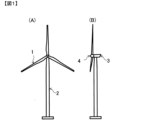
- FIG. 1 is an overall view of a wind turbine for wind power generation.
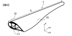
- FIG. 2 is a perspective view showing a wind turbine blade 1 including a cross section taken along a plane perpendicular to the length direction of the wind turbine blade.
- 1A is a side view of a wind turbine blade
- FIG. 1B is a schematic graph showing the relationship between the distance r from the wind turbine root and the spar cap thickness t.
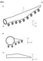
- FIG. 1 is a schematic diagram showing evaluation of the amount of displacement of the tip of a wind turbine blade by applying a pressure simulating wind to the wind turbine blade.
- the length direction of a wind turbine blade refers to the direction of a straight line connecting the center of gravity in a cross section near the part fixed to the hub and the part furthest from the part fixed to the hub (the tip of the blade) (z direction in each drawing).
- the width direction of the wind turbine blade refers to the direction connecting the leading edge and trailing edge in a cross section perpendicular to the length direction of the blade (y direction in each drawing), and the height direction of the wind turbine blade refers to the direction perpendicular to the y and z directions (x direction in each drawing).
- the pressure side refers to the positive pressure side, i.e. the side of the wind turbine blade that the wind hits, and the suction side refers to the reduced pressure side, i.e. the side of the wind turbine blade that the wind leaves.
- the wind turbine blade of the present invention is used in a typical wind turbine for wind power generation, for example as shown in Figures 1 (A) and (B).
- the wind turbine in Figure 1 is mainly composed of a blade 1, a tower 2, a nacelle 3, and a hub 4.
- the blade 1 is attached to the hub 4, and is rotated by wind force, and this rotation is transmitted via the hub 4 to a power transmission shaft in the nacelle 3, driving a generator in the nacelle 3.
- Blade 1 may be configured so that the tip side is bent in advance (pre-bend) in a direction away from tower 2 to make it less likely to collide with tower 2.
- pre-bend the length direction of the wind turbine blade refers to the direction of a straight line connecting the center of gravity of the cross section of the base of the blade to the center of gravity of the cross section of the part furthest from the part fixed to the hub within the range up to the start position of the pre-bend.
- FIG 2 is a perspective view showing a wind turbine blade 1 according to one embodiment of the present invention, including a cross section taken along a plane perpendicular to the blade length.
- the wind turbine blade 1 has a skin 15 consisting of a pressurized side skin and a contraction side skin, a pressurized side spar cap arranged in contact with the inside of the pressurized side skin, a contraction side spar cap arranged in contact with the inside of the contraction side skin (in Figure 2, the pressurized side spar cap and the contraction side spar cap are collectively shown as spar cap 12), and share webs 11 joined at both ends to the pressurized side spar cap and the contraction side spar cap.
- the share web 11 is joined to the blade 1 via a spar cap 12 that extends along the length of the blade along the inner wall of the blade 1.
- the configuration of the share web 11 is not particularly limited, but a sandwich structure consisting of a core material and a skin material is preferably used.
- the core material of the sandwich structure is preferably wood such as balsa or a foamed resin material, and the skin material is preferably a fiber-reinforced resin containing a reinforced fiber fabric.
- the spar cap 12 is essentially composed of a composite material in which reinforcing fibers (typically reinforcing fibers arranged in one direction) are impregnated with resin. More specifically, the spar cap 12 is composed of a plurality of long flat composite materials connected in the length, width and height directions, and reinforces the portion of the wind turbine blade skin 15 that is joined to the share web 11 on the inside of the skin 15.
- “essentially” means that the spar cap may contain other materials (for example, an adhesive between composite materials) as long as it contains a composite material in which reinforcing fibers are impregnated with resin.
- At least one of the pressurized side spar cap and the contracted side spar cap is composed of the aforementioned composite material, but it is preferable that both the pressurized side spar cap and the contracted side spar cap are composed of the aforementioned composite material.
- the preferred method for forming the spar cap is the resin infusion method, in which a number of composite materials that will form the spar cap 12 are arranged lengthwise, widthwise and heightwise on top of the skin 15 that forms the outer shape of the blade, covered with a film that serves as the upper mold, and the space formed between the skin 15, which functions as the lower mold, is kept airtight, and resin is filled between the composite materials using vacuum pressure to connect the composite materials with resin.
- the composite material constituting the spar cap preferably contains carbon fiber as a reinforcing fiber.
- other reinforcing fibers such as glass fiber may be used in addition to carbon fiber.
- the effect of the present invention is particularly pronounced in the case of a composite material using carbon fiber with an elastic modulus of 350 GPa or more.
- the elastic modulus of the carbon fiber is preferably 420 GPa or less.
- the elastic modulus of the reinforcing fiber in the present invention is a value measured in accordance with JIS R7606 (2000).
- the elastic modulus of the composite material in the present invention is preferably 140 GPa or more, and more preferably 175 GPa or more. On the other hand, from the viewpoint of strength, etc., it is preferably 235 GPa or less.
- the elastic modulus of the composite in the present invention is a value measured in accordance with JIS K7161 (2014).
- the resins contained in the composite material are not particularly limited, and include thermosetting resins such as epoxy resins, unsaturated polyester resins, and vinyl ester resins, as well as thermoplastic resins such as polyamide resins, polyolefin resins, polyester resins, polyphenylene sulfide resins, ABS resins, polycarbonate resins, polyacetal resins, and polybutylene terephthalate resins.
- thermosetting resins such as epoxy resins, unsaturated polyester resins, and vinyl ester resins
- thermoplastic resins such as polyamide resins, polyolefin resins, polyester resins, polyphenylene sulfide resins, ABS resins, polycarbonate resins, polyacetal resins, and polybutylene terephthalate resins.
- vinyl ester resins are preferred because they offer an excellent balance between moldability and mechanical properties
- epoxy resins are preferred because they offer excellent mechanical properties and adhesion to carbon fiber.
- the volume content of the reinforcing fibers in the composite material is not limited as long as the required elastic modulus and strength are obtained, but a range of 45 to 75 vol% is preferable because this increases the elastic modulus of the composite material while maintaining moldability. A range of 55 to 72 vol% is more preferable.
- the maximum thickness t max of the spar cap 12 is preferably 90 mm or less, since it is possible to balance the bending rigidity of the blade and the resin impregnation property during the blade manufacturing.
- t max By setting t max to 90 mm or less, it is preferable because defects such as the generation of unimpregnated portions during the resin impregnation are less likely to occur. If t max is 80 mm or less, it is preferable because the possibility of defects such as the generation of unimpregnated resin during the manufacturing is further reduced.
- t max is 50 mm or more.
- the thickness t of the spar cap 12 is measured within a range of ⁇ 20% from the center in the spar cap width direction.
- tmax occurs when r/L is 0.3 to 0.5, since this makes it easier to obtain the rigidity required for the blade. More preferably, it is designed so that tmax occurs when r/L is 0.35 to 0.45.
- At least one of the spar caps has a value calculated from the blade length L, the elastic modulus E of the composite material, and the maximum thickness t max of the spar cap by the following formula (1) of 3.0 or more and less than 6.0, and the maximum value of the plate thickness change rate defined below is 5.0 or less.
- Equation (1) is derived from equation (2) for calculating the deflection of a simple plate-shaped cantilever beam in material mechanics.
- Deflection amount qL4 /(8 ⁇ E ⁇ I) (2)
- q is the load per unit area
- L and E are the length of the beam and the elastic modulus of the constituent material.
- I is the second moment of area, which is derived from the width b and thickness t of the beam.
- An actual blade is composed of many parts such as skins and ribs in addition to the spar cap, and E and I differ for each, requiring a complex design that combines these, but after extensive investigation, the authors found that the blade length L, the maximum thickness t max of the spar cap, and the elastic modulus E of the spar cap are particularly dominant, and derived formula (1).
- the spar cap is too thick or the elastic modulus of the composite material is too large, so that when the blade is deformed, a large shear stress is generated, and the problem of peeling of the composite material occurs.
- the value of formula (1) is 6.0 or more, the spar cap is too thin or the elastic modulus of the composite material is too small, so that the rigidity of the blade is insufficient, and the blade is greatly deformed, so that a large shear stress is generated, and the problem of peeling of the composite material occurs.
- the unit of formula (1) is m/(N/m 2 ), which means the amount of deflection per unit area/load, but in the present invention, by manufacturing the spar cap/wind turbine blade so that the value calculated by this formula is within the above-mentioned specific range, it is possible to suppress peeling and failure of the spar cap, which is a problem especially when a fiber-reinforced resin with a high elastic modulus is used for the spar cap.
- the value of formula (1) is more preferably 3.5 or more and less than 5.0.
- the blade length L is in m
- the elastic modulus E is in GPa
- the maximum thickness t max of the spar cap is in mm as units of calculation.
- the maximum value of the thickness change rate of the spar cap is 5.0 or less.
- the thickness change rate of the spar cap is a value expressed by the absolute value of (t2-t1)/0.5, where t1 is the thickness of the spar cap when the distance r from the root of the spar cap is r1 (here, r1 is an arbitrary distance), and t2 is the thickness of the spar cap at a position away from the distance r1 by a distance of 0.5L on the tip side or the opposite side, and is an index showing the gradualness of the thickness change of the spar cap.
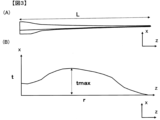
- FIG. 1 the profile of the thickness t of the spar cap (thickness distribution of the spar cap in the blade length direction)
- FIG. 3(A) shows a side view of a wind turbine blade
- FIG. 3(B) shows a schematic graph of the thickness t of the spar cap at the distance r from the root of the wind turbine corresponding to the side view.
- the maximum value of the thickness change rate of the spar cap is 5.0 or less. If the thickness change rate of the spar cap is small, that is, if the transition of the thickness of the spar cap is gradual, peeling between the composite materials is suppressed. If the thickness change rate exceeds 5.0, high shear stress occurs in this portion when the blade undergoes bending deformation, and in particular in the case of a composite material using carbon fibers with a high elastic modulus, peeling occurs between the composite materials, making the blade more likely to be damaged.
- the maximum thickness change rate is preferably 4.0 or less. There is no particular limit to the lower limit of the thickness change rate, but a maximum thickness change rate of less than 2.0 indicates that the thickness of the spar cap is almost uniform, and in order to ensure the minimum required rigidity, it means that an excessive amount of composite material is placed even in a portion that is not actually required, so this is generally not preferable. It is preferable that the position at which the thickness change rate is maximum is located closer to the root side than the position at which the spar cap has the maximum thickness t max .
- At least one of the pressurized side spar cap and the contraction side spar cap has the above-mentioned configuration, but it is preferable that both the pressurized side spar cap and the contraction side spar cap have the above-mentioned configuration.
- the above-mentioned configuration of the present invention is particularly preferably applied to blades with a blade length of 130 m or more, since the above-mentioned peeling problem is particularly pronounced in wind turbines with a blade length of 130 m or more.
- the effects of the present invention are prominent when the above-mentioned configuration is adopted in blades with a blade length of 130 m or more.
- the above-mentioned configuration of the present invention is effective not only against bending deformation of the blade, but also against torsional deformation.
- the blade length be 150 m or less.
- the following shows an example in which the effects of the present invention were verified using a computer simulation.
- the maximum shear stress generated in the spar cap was evaluated as shown in Fig. 4. That is, as shown in the schematic diagram of Fig. 4(A), a distributed load of 5778 Pa was applied to the surface of the wind turbine blade, simulating wind (indicated by the arrow in the figure). Then, the amount of displacement in the x direction of the wind turbine blade tip 14 was evaluated when the wind turbine blade root end 13 was completely restrained around one circumference.
- the surface of the wind turbine blade here refers to the surface that is assumed to receive the wind load when the wind turbine is viewed in the xy plane, as shown in Fig. 4(B), and refers to the surface projected onto the yz plane, as shown in Fig. 4(C).
- the simulation used structural analysis software "NX Nastran” manufactured by SIEMENS.
- the wind turbine was based on the wind turbine model "Definition of the IEA Wind 15MW Offshore Reference Wind Turbine” published by the National Renewable Energy Laboratory (NREL), and the wind turbine blade was composed of a skin, spar cap, and share web as shown in Figure 2.
- the spar cap was composed of a composite material made of carbon fibers arranged in one direction and impregnated with resin. In all examples and comparative examples, the blade length was set to 140 m.
- the elastic modulus E in the wind turbine blade length direction of the composite material used in the analysis and the maximum thickness t max of the spar cap are shown in Table 1.
- the thickness profile of the spar cap was based on the model profile.
- the model profile is as shown in FIG. 3(B), and the position of t max (distance from the blade root at t max ) r is the same as the position r of the model (therefore, the position of t max is at a position where r/L is 0.37), and the value of t max was changed in the examples and comparative examples.
- the thickness is defined according to the plate thickness change rate described in the examples and comparative examples, and from the position where the base thickness defined in the model is reached to the base part, the thickness is constant at the base thickness defined in the model. From the position of t max to the blade tip direction, the plate thickness is defined at a uniform change rate with respect to the plate thickness of the tip defined in the model.
- the longitudinal elastic modulus E of the composite material was determined by multiplying the assumed elastic modulus of the carbon fiber by a volume content of 60% in Examples 1 to 3 and Comparative Examples 1 to 6, and by multiplying it by a volume content of 70% in Examples 4 to 6.
- Example 1 A simulation was performed by assuming a composite material containing carbon fiber with an elastic modulus of 258 GPa, stacking the composite materials so that the fiber direction was the blade length direction and the maximum thickness tmax of the spar cap was the value shown in Table 1, and inputting the physical property values according to Table 1.
- the X-direction displacement (deflection) of the blade tip was 30.2 m, and the clearance with the tower was sufficient.
- the maximum shear stress generated was 13.3 MPa, which was significantly lower than the assumed peel strength of 20 MPa.
- Example 2 A simulation was performed by inputting physical property values according to Table 1 in the same manner as in Example 1, except that the maximum value of the spar cap plate thickness change rate was changed to 7.0.
- the X-direction displacement (deflection) of the blade tip was 30.2 m, and although the clearance with the tower was sufficient, the maximum shear stress generated was 20.4 MPa, a value that would cause peeling and fracture in the spar cap.
- Example 2 Assuming that the composite material of Example 1 was replaced with carbon fiber with a high elastic modulus as the reinforcing fiber, the physical properties of t max and the maximum value of the plate thickness change rate were input according to Table 1, and a simulation was performed. As a result of the analysis, the X-direction displacement (deflection) of the blade tip was 30.3 m, and there was more clearance with the tower. In addition, the maximum shear stress generated was 19.9 MPa, which was lower than the 20 MPa assumed as the peel strength.
- Example 3 The simulation was performed by inputting the physical properties according to Table 1 in the same manner as in Example 2, except that the maximum value of the plate thickness change rate was changed to 3.0. As a result of the analysis, the X-direction displacement (deflection) of the blade tip was 30.2 m, and the clearance with the tower was sufficient. In addition, the maximum shear stress generated was 16.8 MPa, which was lower than the expected peel strength of 20 MPa.
- Example 3 A simulation was performed by inputting physical property values according to Table 1 in the same manner as in Example 2, except that the maximum value of the plate thickness change rate was changed to 7.0.
- the X-direction displacement (deflection) of the blade tip was 30.4 m, and the clearance with the tower was sufficient, but the maximum shear stress generated was 21.9 MPa, a value that would cause peeling and fracture in the spar cap.
- Example 4 A simulation was performed by inputting the physical property values according to Table 1 in the same manner as in Example 2, except that tmax was changed to 60 mm.
- the X-direction displacement (deflection) of the blade tip was 35.2 m, which was a deflection that would cause a tower hit (Example 4).
- the simulation was performed by inputting the physical properties according to Table 1 in the same manner as in Example 1, except that the volume fraction was changed to 70% and tmax was changed to 86 mm.
- the X-direction displacement (deflection) of the blade tip was 30.0 m, and the clearance with the tower was sufficient.
- the maximum shear stress generated was 13.7 MPa, which was significantly lower than the expected peel strength of 20 MPa.
- Example 5 The simulation was performed by inputting the physical properties according to Table 1 in the same manner as in Example 4, except that t max was changed to 83 mm and the plate thickness change rate was changed to 3.8. As a result of the analysis, the X-direction displacement (deflection) of the blade tip was 30.2 m, and the clearance with the tower was sufficient. In addition, the maximum shear stress generated was 11.8 MPa, which was much lower than the assumed peel strength of 20 MPa.
- Example 6 A simulation was performed by inputting the physical properties according to Table 1 in the same manner as in Example 4, except that tmax was changed to 74 mm. As a result of the analysis, the X-direction displacement (deflection) of the blade tip was 32.2 m, and the clearance with the tower was secured. In addition, the maximum shear stress generated was 17.3 MPa, which was lower than the expected peel strength of 20 MPa.
Landscapes
- Engineering & Computer Science (AREA)
- Life Sciences & Earth Sciences (AREA)
- Sustainable Development (AREA)
- Sustainable Energy (AREA)
- Chemical & Material Sciences (AREA)
- Combustion & Propulsion (AREA)
- Mechanical Engineering (AREA)
- General Engineering & Computer Science (AREA)
- Wind Motors (AREA)
Abstract
Afin de fournir une pale d'éolienne dans laquelle une fracture de pelage de semelles de longeron peut être réduite au minimum même lorsqu'une résine renforcée par des fibres de carbone ayant un module d'élasticité élevé est utilisée dans les semelles de longeron, l'invention propose une pale d'éolienne dotée de semelles de longeron disposées en contact avec le côté interne d'une peau côté pression et avec le côté interne d'une peau côté contraction ; au moins l'une des semelles de longeron est essentiellement conçue à partir d'un matériau composite obtenu par imprégnation de fibres de renfort avec une résine ; la valeur calculée en utilisant l'expression (1) ci-dessous à partir de la longueur de pale L de la pale d'éolienne, du module élastique E du matériau composite, et de l'épaisseur maximale tmax des semelles de longeron est égale ou supérieure à 3,0 et inférieure à 6,0 ; et la valeur maximale d'un taux de changement d'épaisseur de plaque selon la définition ci-dessous est inférieure ou égale à 5,0. L'expression (1) est représentée par : L4/(tmax
3×E). Le taux de changement d'épaisseur de plaque est une valeur exprimée par la valeur absolue de (t2− t1)/0,5, t1 étant l'épaisseur de semelle de longeron à une position où la distance r à partir d'une racine de pale est r1, et t2 étant l'épaisseur de semelle de longeron à une position séparée de r1 d'une distance de 0,5L.
Priority Applications (1)
| Application Number | Priority Date | Filing Date | Title |
|---|---|---|---|
| JP2024534694A JPWO2024257699A1 (fr) | 2023-06-14 | 2024-06-07 |
Applications Claiming Priority (2)
| Application Number | Priority Date | Filing Date | Title |
|---|---|---|---|
| JP2023-097432 | 2023-06-14 | ||
| JP2023097432 | 2023-06-14 |
Publications (1)
| Publication Number | Publication Date |
|---|---|
| WO2024257699A1 true WO2024257699A1 (fr) | 2024-12-19 |
Family
ID=93852112
Family Applications (1)
| Application Number | Title | Priority Date | Filing Date |
|---|---|---|---|
| PCT/JP2024/020825 Ceased WO2024257699A1 (fr) | 2023-06-14 | 2024-06-07 | Pale d'éolienne |
Country Status (2)
| Country | Link |
|---|---|
| JP (1) | JPWO2024257699A1 (fr) |
| WO (1) | WO2024257699A1 (fr) |
Citations (2)
| Publication number | Priority date | Publication date | Assignee | Title |
|---|---|---|---|---|
| JP2004308643A (ja) * | 2003-03-24 | 2004-11-04 | Ebara Corp | 垂直軸風車のブレード、垂直軸風車、垂直軸風車のブレードの設計装置および方法、並びに垂直軸風車のブレードの設計プログラム |
| US20140271217A1 (en) * | 2013-03-15 | 2014-09-18 | Modular Wind Energy, Inc. | Efficient wind turbine blade design and associated manufacturing methods using rectangular spars and segmented shear web |
-
2024
- 2024-06-07 WO PCT/JP2024/020825 patent/WO2024257699A1/fr not_active Ceased
- 2024-06-07 JP JP2024534694A patent/JPWO2024257699A1/ja active Pending
Patent Citations (2)
| Publication number | Priority date | Publication date | Assignee | Title |
|---|---|---|---|---|
| JP2004308643A (ja) * | 2003-03-24 | 2004-11-04 | Ebara Corp | 垂直軸風車のブレード、垂直軸風車、垂直軸風車のブレードの設計装置および方法、並びに垂直軸風車のブレードの設計プログラム |
| US20140271217A1 (en) * | 2013-03-15 | 2014-09-18 | Modular Wind Energy, Inc. | Efficient wind turbine blade design and associated manufacturing methods using rectangular spars and segmented shear web |
Also Published As
| Publication number | Publication date |
|---|---|
| JPWO2024257699A1 (fr) | 2024-12-19 |
Similar Documents
| Publication | Publication Date | Title |
|---|---|---|
| CN100376790C (zh) | 具有碳纤维尖部的风力涡轮机叶片 | |
| CN1328500C (zh) | 风力涡轮机叶片上的过渡区 | |
| CN102465826B (zh) | 用于风机转子叶片的主梁帽组件 | |
| EP2224127B1 (fr) | Semelle de longeron améliorée pour pâles d'éoliennes | |
| EP2511477B1 (fr) | Pale d'éolienne dotée d'une région de transition | |
| CA2884412C (fr) | Element composite renforce de fibres pour la pale de rotor d'une eolienne | |
| CN103958835B (zh) | 具有过渡区域的风力涡轮机叶片 | |
| CN108700028B (zh) | 风力涡轮机叶片及相关制造方法 | |
| CN111720260A (zh) | 风力涡轮机叶片和风力涡轮机 | |
| US12589556B2 (en) | Pultruded fibre-reinforced strip for a reinforced structure, such as a spar cap | |
| JP5484892B2 (ja) | 風車回転翼 | |
| CN106286114A (zh) | 用于风力涡轮转子叶片的具有不同面积重量纤维增强层的结构支承部件 | |
| CN113939651A (zh) | 壳体芯和具有包括此类壳体芯的叶片壳体的风力涡轮机叶片 | |
| WO2011078337A1 (fr) | Pale rotative d'éolienne | |
| WO2024257699A1 (fr) | Pale d'éolienne | |
| US12429025B2 (en) | Wind turbine blade and a method for manufacturing a wind turbine blade | |
| EP4305300B1 (fr) | Capuchon de longeron de pale de rotor d'éolienne à liaison équipotentielle | |
| WO2024190111A1 (fr) | Pale d'éolienne | |
| JP2016125441A (ja) | 風車翼 | |
| CN117616196A (zh) | 风力涡轮机叶片 | |
| JP2023004899A (ja) | 風車翼 | |
| EP3946909B1 (fr) | Fabrication d'une partie de coque renforcée d'une pale d'éolienne | |
| JP2024062016A (ja) | 風車翼 | |
| WO2024203216A1 (fr) | Pale d'éolienne | |
| CN116412060B (zh) | 叶片的腹板及叶片 |
Legal Events
| Date | Code | Title | Description |
|---|---|---|---|
| WWE | Wipo information: entry into national phase |
Ref document number: 2024534694 Country of ref document: JP |
|
| 121 | Ep: the epo has been informed by wipo that ep was designated in this application |
Ref document number: 24823315 Country of ref document: EP Kind code of ref document: A1 |
|
| NENP | Non-entry into the national phase |
Ref country code: DE |