WO2024257699A1 - 風車ブレード - Google Patents
風車ブレード Download PDFInfo
- Publication number
- WO2024257699A1 WO2024257699A1 PCT/JP2024/020825 JP2024020825W WO2024257699A1 WO 2024257699 A1 WO2024257699 A1 WO 2024257699A1 JP 2024020825 W JP2024020825 W JP 2024020825W WO 2024257699 A1 WO2024257699 A1 WO 2024257699A1
- Authority
- WO
- WIPO (PCT)
- Prior art keywords
- wind turbine
- turbine blade
- spar cap
- blade
- composite material
- Prior art date
- Legal status (The legal status is an assumption and is not a legal conclusion. Google has not performed a legal analysis and makes no representation as to the accuracy of the status listed.)
- Ceased
Links
Images
Classifications
-
- F—MECHANICAL ENGINEERING; LIGHTING; HEATING; WEAPONS; BLASTING
- F03—MACHINES OR ENGINES FOR LIQUIDS; WIND, SPRING, OR WEIGHT MOTORS; PRODUCING MECHANICAL POWER OR A REACTIVE PROPULSIVE THRUST, NOT OTHERWISE PROVIDED FOR
- F03D—WIND MOTORS
- F03D1/00—Wind motors with rotation axis substantially parallel to the air flow entering the rotor
- F03D1/06—Rotors
-
- Y—GENERAL TAGGING OF NEW TECHNOLOGICAL DEVELOPMENTS; GENERAL TAGGING OF CROSS-SECTIONAL TECHNOLOGIES SPANNING OVER SEVERAL SECTIONS OF THE IPC; TECHNICAL SUBJECTS COVERED BY FORMER USPC CROSS-REFERENCE ART COLLECTIONS [XRACs] AND DIGESTS
- Y02—TECHNOLOGIES OR APPLICATIONS FOR MITIGATION OR ADAPTATION AGAINST CLIMATE CHANGE
- Y02E—REDUCTION OF GREENHOUSE GAS [GHG] EMISSIONS, RELATED TO ENERGY GENERATION, TRANSMISSION OR DISTRIBUTION
- Y02E10/00—Energy generation through renewable energy sources
- Y02E10/70—Wind energy
- Y02E10/72—Wind turbines with rotation axis in wind direction
Definitions
- the present invention relates to wind turbine blades used in wind turbines for wind power generation, etc.
- glass fiber reinforced resin a relatively inexpensive material, has often been used for wind turbine blades.
- the mechanical properties of glass fiber reinforced resin are insufficient, and the bending deformation of the wind turbine blades becomes significant. As a result, the blades come into contact with the tower that supports them, resulting in the problem of the blades being damaged.
- Non-Patent Document 1 considers increasing the rigidity of the 117m blade by using carbon fiber reinforced resin, which has better mechanical properties than glass fiber reinforced resin. Patent Document 1 also considers devising a thickness for the spar cap, which uses carbon fiber reinforced resin.
- Non-Patent Document 1 does not consider increasing rigidity for longer blade lengths. Furthermore, Patent Document 1 only discloses technology that is more effective for blades in the 50-100m range compared to blades with lengths of 35-55m, and the effectiveness is not verified for extra-large blades exceeding 100m.
- the spar cap of a wind turbine blade is constructed by connecting multiple long, flat composite materials, in which reinforcing fibers are impregnated with resin, in the length, width and height directions.
- resin in which reinforcing fibers are impregnated with resin, in the length, width and height directions.
- rigidity can be ensured by using a composite material made of a higher elasticity carbon fiber reinforced resin for the spar cap.
- the present invention aims to prevent peeling and failure of spar caps even when a composite material made of carbon fiber reinforced resin with a high elastic modulus is used for the spar caps of wind turbine blades.
- a value calculated from the blade length L of the wind turbine blade, the elastic modulus E of the composite material, and the maximum thickness t max of the spar cap by the following formula (1) is 3.0 or more and less than 6.0, And the maximum thickness change rate defined below is 5.0 or less.
- Plate thickness change rate a value expressed by the absolute value of (t2-t1)/0.5, where t1 is the spar cap thickness at a distance r from the blade root, r1, and t2 is the spar cap thickness at a position a distance 0.5L away from r1.
- the wind turbine blade according to 1 wherein the value calculated by the formula (1) is 3.5 or more and less than 5.0.
- the wind turbine blade according to 1 or 2 wherein the maximum value of the plate thickness change rate is 4.0 or less.
- the wind turbine blade according to any one of 1 to 3 wherein the blade length L is 130 m or more.
- the wind turbine blade according to any one of 1 to 4 wherein the spar cap has a maximum thickness t max of 90 mm or less.
- the composite material is a composite material in which reinforcing fibers arranged in one direction are impregnated with resin.
- the wind turbine blade according to 8, wherein the elastic modulus E of the carbon fiber is 350 GPa or more.
- a wind turbine for wind power generation comprising the wind turbine blade according to any one of 1 to 9.
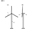
- FIG. 1 is an overall view of a wind turbine for wind power generation.
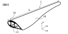
- FIG. 2 is a perspective view showing a wind turbine blade 1 including a cross section taken along a plane perpendicular to the length direction of the wind turbine blade.
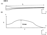
- 1A is a side view of a wind turbine blade
- FIG. 1B is a schematic graph showing the relationship between the distance r from the wind turbine root and the spar cap thickness t.
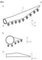
- FIG. 1 is a schematic diagram showing evaluation of the amount of displacement of the tip of a wind turbine blade by applying a pressure simulating wind to the wind turbine blade.
- the length direction of a wind turbine blade refers to the direction of a straight line connecting the center of gravity in a cross section near the part fixed to the hub and the part furthest from the part fixed to the hub (the tip of the blade) (z direction in each drawing).
- the width direction of the wind turbine blade refers to the direction connecting the leading edge and trailing edge in a cross section perpendicular to the length direction of the blade (y direction in each drawing), and the height direction of the wind turbine blade refers to the direction perpendicular to the y and z directions (x direction in each drawing).
- the pressure side refers to the positive pressure side, i.e. the side of the wind turbine blade that the wind hits, and the suction side refers to the reduced pressure side, i.e. the side of the wind turbine blade that the wind leaves.
- the wind turbine blade of the present invention is used in a typical wind turbine for wind power generation, for example as shown in Figures 1 (A) and (B).
- the wind turbine in Figure 1 is mainly composed of a blade 1, a tower 2, a nacelle 3, and a hub 4.
- the blade 1 is attached to the hub 4, and is rotated by wind force, and this rotation is transmitted via the hub 4 to a power transmission shaft in the nacelle 3, driving a generator in the nacelle 3.
- Blade 1 may be configured so that the tip side is bent in advance (pre-bend) in a direction away from tower 2 to make it less likely to collide with tower 2.
- pre-bend the length direction of the wind turbine blade refers to the direction of a straight line connecting the center of gravity of the cross section of the base of the blade to the center of gravity of the cross section of the part furthest from the part fixed to the hub within the range up to the start position of the pre-bend.
- FIG 2 is a perspective view showing a wind turbine blade 1 according to one embodiment of the present invention, including a cross section taken along a plane perpendicular to the blade length.
- the wind turbine blade 1 has a skin 15 consisting of a pressurized side skin and a contraction side skin, a pressurized side spar cap arranged in contact with the inside of the pressurized side skin, a contraction side spar cap arranged in contact with the inside of the contraction side skin (in Figure 2, the pressurized side spar cap and the contraction side spar cap are collectively shown as spar cap 12), and share webs 11 joined at both ends to the pressurized side spar cap and the contraction side spar cap.
- the share web 11 is joined to the blade 1 via a spar cap 12 that extends along the length of the blade along the inner wall of the blade 1.
- the configuration of the share web 11 is not particularly limited, but a sandwich structure consisting of a core material and a skin material is preferably used.
- the core material of the sandwich structure is preferably wood such as balsa or a foamed resin material, and the skin material is preferably a fiber-reinforced resin containing a reinforced fiber fabric.
- the spar cap 12 is essentially composed of a composite material in which reinforcing fibers (typically reinforcing fibers arranged in one direction) are impregnated with resin. More specifically, the spar cap 12 is composed of a plurality of long flat composite materials connected in the length, width and height directions, and reinforces the portion of the wind turbine blade skin 15 that is joined to the share web 11 on the inside of the skin 15.
- “essentially” means that the spar cap may contain other materials (for example, an adhesive between composite materials) as long as it contains a composite material in which reinforcing fibers are impregnated with resin.
- At least one of the pressurized side spar cap and the contracted side spar cap is composed of the aforementioned composite material, but it is preferable that both the pressurized side spar cap and the contracted side spar cap are composed of the aforementioned composite material.
- the preferred method for forming the spar cap is the resin infusion method, in which a number of composite materials that will form the spar cap 12 are arranged lengthwise, widthwise and heightwise on top of the skin 15 that forms the outer shape of the blade, covered with a film that serves as the upper mold, and the space formed between the skin 15, which functions as the lower mold, is kept airtight, and resin is filled between the composite materials using vacuum pressure to connect the composite materials with resin.
- the composite material constituting the spar cap preferably contains carbon fiber as a reinforcing fiber.
- other reinforcing fibers such as glass fiber may be used in addition to carbon fiber.
- the effect of the present invention is particularly pronounced in the case of a composite material using carbon fiber with an elastic modulus of 350 GPa or more.
- the elastic modulus of the carbon fiber is preferably 420 GPa or less.
- the elastic modulus of the reinforcing fiber in the present invention is a value measured in accordance with JIS R7606 (2000).
- the elastic modulus of the composite material in the present invention is preferably 140 GPa or more, and more preferably 175 GPa or more. On the other hand, from the viewpoint of strength, etc., it is preferably 235 GPa or less.
- the elastic modulus of the composite in the present invention is a value measured in accordance with JIS K7161 (2014).
- the resins contained in the composite material are not particularly limited, and include thermosetting resins such as epoxy resins, unsaturated polyester resins, and vinyl ester resins, as well as thermoplastic resins such as polyamide resins, polyolefin resins, polyester resins, polyphenylene sulfide resins, ABS resins, polycarbonate resins, polyacetal resins, and polybutylene terephthalate resins.
- thermosetting resins such as epoxy resins, unsaturated polyester resins, and vinyl ester resins
- thermoplastic resins such as polyamide resins, polyolefin resins, polyester resins, polyphenylene sulfide resins, ABS resins, polycarbonate resins, polyacetal resins, and polybutylene terephthalate resins.
- vinyl ester resins are preferred because they offer an excellent balance between moldability and mechanical properties
- epoxy resins are preferred because they offer excellent mechanical properties and adhesion to carbon fiber.
- the volume content of the reinforcing fibers in the composite material is not limited as long as the required elastic modulus and strength are obtained, but a range of 45 to 75 vol% is preferable because this increases the elastic modulus of the composite material while maintaining moldability. A range of 55 to 72 vol% is more preferable.
- the maximum thickness t max of the spar cap 12 is preferably 90 mm or less, since it is possible to balance the bending rigidity of the blade and the resin impregnation property during the blade manufacturing.
- t max By setting t max to 90 mm or less, it is preferable because defects such as the generation of unimpregnated portions during the resin impregnation are less likely to occur. If t max is 80 mm or less, it is preferable because the possibility of defects such as the generation of unimpregnated resin during the manufacturing is further reduced.
- t max is 50 mm or more.
- the thickness t of the spar cap 12 is measured within a range of ⁇ 20% from the center in the spar cap width direction.
- tmax occurs when r/L is 0.3 to 0.5, since this makes it easier to obtain the rigidity required for the blade. More preferably, it is designed so that tmax occurs when r/L is 0.35 to 0.45.
- At least one of the spar caps has a value calculated from the blade length L, the elastic modulus E of the composite material, and the maximum thickness t max of the spar cap by the following formula (1) of 3.0 or more and less than 6.0, and the maximum value of the plate thickness change rate defined below is 5.0 or less.
- Equation (1) is derived from equation (2) for calculating the deflection of a simple plate-shaped cantilever beam in material mechanics.
- Deflection amount qL4 /(8 ⁇ E ⁇ I) (2)
- q is the load per unit area
- L and E are the length of the beam and the elastic modulus of the constituent material.
- I is the second moment of area, which is derived from the width b and thickness t of the beam.
- An actual blade is composed of many parts such as skins and ribs in addition to the spar cap, and E and I differ for each, requiring a complex design that combines these, but after extensive investigation, the authors found that the blade length L, the maximum thickness t max of the spar cap, and the elastic modulus E of the spar cap are particularly dominant, and derived formula (1).
- the spar cap is too thick or the elastic modulus of the composite material is too large, so that when the blade is deformed, a large shear stress is generated, and the problem of peeling of the composite material occurs.
- the value of formula (1) is 6.0 or more, the spar cap is too thin or the elastic modulus of the composite material is too small, so that the rigidity of the blade is insufficient, and the blade is greatly deformed, so that a large shear stress is generated, and the problem of peeling of the composite material occurs.
- the unit of formula (1) is m/(N/m 2 ), which means the amount of deflection per unit area/load, but in the present invention, by manufacturing the spar cap/wind turbine blade so that the value calculated by this formula is within the above-mentioned specific range, it is possible to suppress peeling and failure of the spar cap, which is a problem especially when a fiber-reinforced resin with a high elastic modulus is used for the spar cap.
- the value of formula (1) is more preferably 3.5 or more and less than 5.0.
- the blade length L is in m
- the elastic modulus E is in GPa
- the maximum thickness t max of the spar cap is in mm as units of calculation.
- the maximum value of the thickness change rate of the spar cap is 5.0 or less.
- the thickness change rate of the spar cap is a value expressed by the absolute value of (t2-t1)/0.5, where t1 is the thickness of the spar cap when the distance r from the root of the spar cap is r1 (here, r1 is an arbitrary distance), and t2 is the thickness of the spar cap at a position away from the distance r1 by a distance of 0.5L on the tip side or the opposite side, and is an index showing the gradualness of the thickness change of the spar cap.
- FIG. 1 the profile of the thickness t of the spar cap (thickness distribution of the spar cap in the blade length direction)
- FIG. 3(A) shows a side view of a wind turbine blade
- FIG. 3(B) shows a schematic graph of the thickness t of the spar cap at the distance r from the root of the wind turbine corresponding to the side view.
- the maximum value of the thickness change rate of the spar cap is 5.0 or less. If the thickness change rate of the spar cap is small, that is, if the transition of the thickness of the spar cap is gradual, peeling between the composite materials is suppressed. If the thickness change rate exceeds 5.0, high shear stress occurs in this portion when the blade undergoes bending deformation, and in particular in the case of a composite material using carbon fibers with a high elastic modulus, peeling occurs between the composite materials, making the blade more likely to be damaged.
- the maximum thickness change rate is preferably 4.0 or less. There is no particular limit to the lower limit of the thickness change rate, but a maximum thickness change rate of less than 2.0 indicates that the thickness of the spar cap is almost uniform, and in order to ensure the minimum required rigidity, it means that an excessive amount of composite material is placed even in a portion that is not actually required, so this is generally not preferable. It is preferable that the position at which the thickness change rate is maximum is located closer to the root side than the position at which the spar cap has the maximum thickness t max .
- At least one of the pressurized side spar cap and the contraction side spar cap has the above-mentioned configuration, but it is preferable that both the pressurized side spar cap and the contraction side spar cap have the above-mentioned configuration.
- the above-mentioned configuration of the present invention is particularly preferably applied to blades with a blade length of 130 m or more, since the above-mentioned peeling problem is particularly pronounced in wind turbines with a blade length of 130 m or more.
- the effects of the present invention are prominent when the above-mentioned configuration is adopted in blades with a blade length of 130 m or more.
- the above-mentioned configuration of the present invention is effective not only against bending deformation of the blade, but also against torsional deformation.
- the blade length be 150 m or less.
- the following shows an example in which the effects of the present invention were verified using a computer simulation.
- the maximum shear stress generated in the spar cap was evaluated as shown in Fig. 4. That is, as shown in the schematic diagram of Fig. 4(A), a distributed load of 5778 Pa was applied to the surface of the wind turbine blade, simulating wind (indicated by the arrow in the figure). Then, the amount of displacement in the x direction of the wind turbine blade tip 14 was evaluated when the wind turbine blade root end 13 was completely restrained around one circumference.
- the surface of the wind turbine blade here refers to the surface that is assumed to receive the wind load when the wind turbine is viewed in the xy plane, as shown in Fig. 4(B), and refers to the surface projected onto the yz plane, as shown in Fig. 4(C).
- the simulation used structural analysis software "NX Nastran” manufactured by SIEMENS.
- the wind turbine was based on the wind turbine model "Definition of the IEA Wind 15MW Offshore Reference Wind Turbine” published by the National Renewable Energy Laboratory (NREL), and the wind turbine blade was composed of a skin, spar cap, and share web as shown in Figure 2.
- the spar cap was composed of a composite material made of carbon fibers arranged in one direction and impregnated with resin. In all examples and comparative examples, the blade length was set to 140 m.
- the elastic modulus E in the wind turbine blade length direction of the composite material used in the analysis and the maximum thickness t max of the spar cap are shown in Table 1.
- the thickness profile of the spar cap was based on the model profile.
- the model profile is as shown in FIG. 3(B), and the position of t max (distance from the blade root at t max ) r is the same as the position r of the model (therefore, the position of t max is at a position where r/L is 0.37), and the value of t max was changed in the examples and comparative examples.
- the thickness is defined according to the plate thickness change rate described in the examples and comparative examples, and from the position where the base thickness defined in the model is reached to the base part, the thickness is constant at the base thickness defined in the model. From the position of t max to the blade tip direction, the plate thickness is defined at a uniform change rate with respect to the plate thickness of the tip defined in the model.
- the longitudinal elastic modulus E of the composite material was determined by multiplying the assumed elastic modulus of the carbon fiber by a volume content of 60% in Examples 1 to 3 and Comparative Examples 1 to 6, and by multiplying it by a volume content of 70% in Examples 4 to 6.
- Example 1 A simulation was performed by assuming a composite material containing carbon fiber with an elastic modulus of 258 GPa, stacking the composite materials so that the fiber direction was the blade length direction and the maximum thickness tmax of the spar cap was the value shown in Table 1, and inputting the physical property values according to Table 1.
- the X-direction displacement (deflection) of the blade tip was 30.2 m, and the clearance with the tower was sufficient.
- the maximum shear stress generated was 13.3 MPa, which was significantly lower than the assumed peel strength of 20 MPa.
- Example 2 A simulation was performed by inputting physical property values according to Table 1 in the same manner as in Example 1, except that the maximum value of the spar cap plate thickness change rate was changed to 7.0.
- the X-direction displacement (deflection) of the blade tip was 30.2 m, and although the clearance with the tower was sufficient, the maximum shear stress generated was 20.4 MPa, a value that would cause peeling and fracture in the spar cap.
- Example 2 Assuming that the composite material of Example 1 was replaced with carbon fiber with a high elastic modulus as the reinforcing fiber, the physical properties of t max and the maximum value of the plate thickness change rate were input according to Table 1, and a simulation was performed. As a result of the analysis, the X-direction displacement (deflection) of the blade tip was 30.3 m, and there was more clearance with the tower. In addition, the maximum shear stress generated was 19.9 MPa, which was lower than the 20 MPa assumed as the peel strength.
- Example 3 The simulation was performed by inputting the physical properties according to Table 1 in the same manner as in Example 2, except that the maximum value of the plate thickness change rate was changed to 3.0. As a result of the analysis, the X-direction displacement (deflection) of the blade tip was 30.2 m, and the clearance with the tower was sufficient. In addition, the maximum shear stress generated was 16.8 MPa, which was lower than the expected peel strength of 20 MPa.
- Example 3 A simulation was performed by inputting physical property values according to Table 1 in the same manner as in Example 2, except that the maximum value of the plate thickness change rate was changed to 7.0.
- the X-direction displacement (deflection) of the blade tip was 30.4 m, and the clearance with the tower was sufficient, but the maximum shear stress generated was 21.9 MPa, a value that would cause peeling and fracture in the spar cap.
- Example 4 A simulation was performed by inputting the physical property values according to Table 1 in the same manner as in Example 2, except that tmax was changed to 60 mm.
- the X-direction displacement (deflection) of the blade tip was 35.2 m, which was a deflection that would cause a tower hit (Example 4).
- the simulation was performed by inputting the physical properties according to Table 1 in the same manner as in Example 1, except that the volume fraction was changed to 70% and tmax was changed to 86 mm.
- the X-direction displacement (deflection) of the blade tip was 30.0 m, and the clearance with the tower was sufficient.
- the maximum shear stress generated was 13.7 MPa, which was significantly lower than the expected peel strength of 20 MPa.
- Example 5 The simulation was performed by inputting the physical properties according to Table 1 in the same manner as in Example 4, except that t max was changed to 83 mm and the plate thickness change rate was changed to 3.8. As a result of the analysis, the X-direction displacement (deflection) of the blade tip was 30.2 m, and the clearance with the tower was sufficient. In addition, the maximum shear stress generated was 11.8 MPa, which was much lower than the assumed peel strength of 20 MPa.
- Example 6 A simulation was performed by inputting the physical properties according to Table 1 in the same manner as in Example 4, except that tmax was changed to 74 mm. As a result of the analysis, the X-direction displacement (deflection) of the blade tip was 32.2 m, and the clearance with the tower was secured. In addition, the maximum shear stress generated was 17.3 MPa, which was lower than the expected peel strength of 20 MPa.
Landscapes
- Engineering & Computer Science (AREA)
- Life Sciences & Earth Sciences (AREA)
- Sustainable Development (AREA)
- Sustainable Energy (AREA)
- Chemical & Material Sciences (AREA)
- Combustion & Propulsion (AREA)
- Mechanical Engineering (AREA)
- General Engineering & Computer Science (AREA)
- Wind Motors (AREA)
Abstract
高弾性率の炭素繊維強化樹脂をスパーキャップに用いた場合にもスパーキャップの剥離破壊を抑制できる風車ブレードとするため、加圧側スキンの内側と、収縮側スキンの内側とにそれぞれ接して配置されたスパーキャップを有する風車ブレードであって、前記スパーキャップの少なくとも一方は、強化繊維に樹脂が含浸してなるコンポジット材から本質的に構成され、前記風車ブレードのブレード長Lと、前記コンポジット材の弾性率Eと、前記スパーキャップの最大厚さtmaxとから、下記式(1)により算出される値が3.0以上6.0未満であり、かつ、下記の定義による板厚変化率の最大値が5.0以下である風車ブレードとする。 L4/(tmax
3×E) ・・・(1) 板厚変化率:ブレード根元からの距離rがr1におけるスパーキャップ厚さをt1、r1から距離0.5Lだけ離れた位置におけるスパーキャップ厚さをt2としたとき、(t2-t1)/0.5の絶対値で表される値
Description
本発明は、風力発電用風車などに使用される風車ブレードに関する。
近年、風力発電用の風車ブレードは、より大きな発電量を得るために長大化してきている。風車ブレードを長大化することで、風を受ける面積を大きくすることができる反面、回転に伴う遠心力や風力に負けない剛性を確保する必要がある。
風車ブレードの材料としては、これまでは、コストが比較的安いガラス繊維強化樹脂が使われることが多かった。しかし、100mを超える超大型のブレードではガラス繊維強化樹脂では力学特性が足りなくなり、風車ブレードの曲げ変形が大きくなる。その結果、ブレードを支えるタワーとブレードが接触し、ブレードが破損するという課題が顕在化している。
このような課題に対して、非特許文献1では、117mのブレードにおいて、ガラス繊維強化樹脂より力学特性に優れる炭素繊維強化樹脂を用いることで、ブレードの剛性を高める検討がなされている。また、特許文献1では、炭素繊維強化樹脂を用いるスパーキャップの厚さを工夫する検討がなされている。
Definition of the IEA Wind 15MW Offshore Reference Wind Turbine(2020)
しかしながら、非特許文献1では、さらに長いブレード長に対して剛性を高める検討はなされていない。また、特許文献1は、35~55mのブレード長のものと比較して、50~100mの範囲のブレードにおいてより有効である技術が開示されているのみであり、100mを超える超大型のブレードについては、効果は検証されていない。
風車ブレードのスパーキャップは、強化繊維に樹脂が含浸してなる長尺平板上のコンポジット材を、長さ方向、幅方向および高さ方向に複数枚連結することによって構成されている。一般的には、超大型のブレードに対応するためには、より高弾性の炭素繊維強化樹脂からなるコンポジット材をスパーキャップに用いることで、剛性を確保することが考えられる。しかし、本発明者らの検討によれば、高弾性率の炭素繊維強化樹脂は荷重がかかった際の相互の接着性が低下するため、単にガラス繊維強化樹脂のコンポジット材を高弾性率の炭素繊維強化樹脂のコンポジット材に置き換えるだけでは、コンポジット材同士の間で剥離破壊が発生するという新たな課題が発生すると考えられた。
そこで、本発明は、風車ブレードにおいて高弾性率の炭素繊維強化樹脂からなるコンポジット材をスパーキャップに用いた場合でも、スパーキャップの剥離破壊を抑制することを課題とする。
上記課題を解決するための本発明は、以下のものである。
[1]加圧側スキンの内側と、収縮側スキンの内側とにそれぞれ接して配置されたスパーキャップを有する風車ブレードであって、
前記スパーキャップの少なくとも一方は、強化繊維に樹脂が含浸してなるコンポジット材から本質的に構成され、
前記風車ブレードのブレード長Lと、前記コンポジット材の弾性率Eと、前記スパーキャップの最大厚さtmaxとから、下記式(1)により算出される値が3.0以上6.0未満であり、
かつ、下記の定義による板厚変化率の最大値が5.0以下である風車ブレード。
L4/(tmax 3×E) ・・・(1)
板厚変化率:ブレード根元からの距離rがr1におけるスパーキャップ厚さをt1、r1から距離0.5Lだけ離れた位置におけるスパーキャップ厚さをt2としたとき、(t2-t1)/0.5の絶対値で表される値
[2]前記式(1)により算出される値が3.5以上5.0未満である、1に記載の風車ブレード。
[3]前記板厚変化率の最大値が4.0以下である、1または2に記載の風車ブレード。
[4]前記ブレード長Lが130m以上である、1~3のいずれかに記載の風車ブレード。
[5]前記スパーキャップの最大厚さtmaxが90mm以下である、1~4のいずれかに記載の風車ブレード。
[6]前記スパーキャップは、r/Lが0.3~0.5の位置において最も厚くなるよう構成される、1~5のいずれかに記載の風車ブレード。
[7]前記コンポジット材が一方向に配列された強化繊維に樹脂が含浸してなるコンポジット材である、1~6のいずれかに記載の風車ブレード。
[8]前記コンポジット材に含まれる強化繊維が炭素繊維である、1~7のいずれかに記載の風車ブレード。
[9]前記炭素繊維の弾性率Eが350GPa以上である、8に記載の風車ブレード。
[10]1~9のいずれかに記載の風車ブレードを備えた風力発電用風車。
[1]加圧側スキンの内側と、収縮側スキンの内側とにそれぞれ接して配置されたスパーキャップを有する風車ブレードであって、
前記スパーキャップの少なくとも一方は、強化繊維に樹脂が含浸してなるコンポジット材から本質的に構成され、
前記風車ブレードのブレード長Lと、前記コンポジット材の弾性率Eと、前記スパーキャップの最大厚さtmaxとから、下記式(1)により算出される値が3.0以上6.0未満であり、
かつ、下記の定義による板厚変化率の最大値が5.0以下である風車ブレード。
L4/(tmax 3×E) ・・・(1)
板厚変化率:ブレード根元からの距離rがr1におけるスパーキャップ厚さをt1、r1から距離0.5Lだけ離れた位置におけるスパーキャップ厚さをt2としたとき、(t2-t1)/0.5の絶対値で表される値
[2]前記式(1)により算出される値が3.5以上5.0未満である、1に記載の風車ブレード。
[3]前記板厚変化率の最大値が4.0以下である、1または2に記載の風車ブレード。
[4]前記ブレード長Lが130m以上である、1~3のいずれかに記載の風車ブレード。
[5]前記スパーキャップの最大厚さtmaxが90mm以下である、1~4のいずれかに記載の風車ブレード。
[6]前記スパーキャップは、r/Lが0.3~0.5の位置において最も厚くなるよう構成される、1~5のいずれかに記載の風車ブレード。
[7]前記コンポジット材が一方向に配列された強化繊維に樹脂が含浸してなるコンポジット材である、1~6のいずれかに記載の風車ブレード。
[8]前記コンポジット材に含まれる強化繊維が炭素繊維である、1~7のいずれかに記載の風車ブレード。
[9]前記炭素繊維の弾性率Eが350GPa以上である、8に記載の風車ブレード。
[10]1~9のいずれかに記載の風車ブレードを備えた風力発電用風車。
本発明によれば、風車ブレードのスパーキャップとして高弾性率の炭素繊維強化樹脂製のコンポジット材を用いた場合でも、スパーキャップ内でのコンポジット材同士の剥離を抑制することができる。
本明細書において、風車ブレード(以下、単にブレードという場合がある)の長さ方向とは、ハブへの固定部分近傍の断面における重心と、ハブへの固定部分から最も離れている部分(ブレード先端)を繋ぐ直線の方向(各図面におけるz方向)を指すものとする。風車ブレード幅方向とは、ブレード長さ方向に垂直な断面において、リーディングエッジとトレーリングエッジとをつなぐ方向(各図面におけるy方向)を指し、風車ブレード高さ方向とは、当該y方向およびz方向に垂直な方向(各図面におけるx方向)を指す。
また、加圧側(pressure-side)とは、正圧側、すなわち風車ブレードの、風が当たる側をいい、収縮側(suctionside)とは、減圧側、すなわち風車ブレードの、風が離れる側をいう。
以下に、本発明の実施の形態を、図面を参照しながら説明する。なお、図面に示される特定の実施形態についての説明は、上位概念としての本発明の説明としても理解し得るものである。
本発明の風車ブレードは、例えば図1の(A)および(B)に示すような典型的な風力発電用風車に用いられる。図1の風車は、主に、ブレード1、タワー2、ナセル3、ハブ4から構成される。ブレード1はハブ4に取り付けられており、風力によってブレード1が回転し、その回転がハブ4を介してナセル3内の動力伝達軸に伝わり、ナセル3内の発電機が駆動される。
ブレード1は、タワー2に衝突しにくいように、タワー2から離れる向きに先端側をあらかじめ曲げた構成(プリベンド)となっていても良い。なお、プリベンドの場合の風車ブレード長さ方向とは、ブレード根元の断面の重心と、プリベンドの開始位置までの範囲でハブへの固定部分から最も離れている部分の断面の重心と、を繋ぐ直線の方向のことを指す。
図2は、本発明の一実施形態である風車ブレード1を、ブレード長さ方向に垂直な面で切った場合の断面を含めて示す斜視図である。風車ブレード1は、加圧側スキンと収縮側スキンとからなるスキン15と、加圧側スキンの内側に接して配置された加圧側スパーキャップと、収縮側スキンの内側に接して配置された収縮側スパーキャップと(図2中、加圧側スパーキャップと収縮側スパーキャップとを併せてスパーキャップ12として示している)、加圧側スパーキャップおよび収縮側スパーキャップとに両端で接合されたシェアウェブ11とを有する。
シェアウェブ11は、ブレード1の内壁に沿ってブレード長さ方向に延在するスパーキャップ12を介して、ブレード1に接合されている。
シェアウェブ11の構成は特に限定されるものではないが、コア材とスキン材からなるサンドイッチ構造を有するものが好適に用いられる。サンドイッチ構造のコア材としてはバルサなどの木材や発泡樹脂材が、スキン材としては強化繊維織物を含む繊維強化樹脂などが好ましく使用される。
本発明において、スパーキャップ12は、強化繊維(典型的には一方向に配列された強化繊維)に樹脂が含浸してなるコンポジット材から本質的に構成されている。より具体的には、スパーキャップ12は、長尺平板上のコンポジット材を、長さ方向、幅方向および高さ方向に複数枚連結することによって構成され、風車ブレードのスキン15の内側におけるシェアウェブ11と接合する部分を補強している。ここで「本質的」とは、スパーキャップが強化繊維に樹脂が含浸してなるコンポジット材を含んでいる限り、他の材料(例えばコンポジット材とコンポジット材との間に存在する接着剤などがあげられる)を含んでいてもよいことを意味する。また、本発明においては、加圧側スパーキャップおよび収縮側スパーキャップの少なくとも一方が前述のコンポジット材から構成されていればよいが、加圧側スパーキャップおよび収縮側スパーキャップの両方が前述のコンポジット材から構成されていることが好ましい。
スパーキャップの成形方法としては、ブレードの外形となるスキン15の上にスパーキャップ12の材料となる多数のコンポジット材を長さ方向、幅方向および高さ方向に配列し、上型となるフィルムで被覆し、下型として機能するスキン15との間に形成された空間の気密性を保った上で、真空圧によってコンポジット材の間に樹脂を充填させることでそれらコンポジット材を樹脂で連結する、レジンインフュージョン法が好適である。
本発明においては、スパーキャップを構成するコンポジット材は、強化繊維として炭素繊維を含んでいることが好ましい。コストを抑える観点からは、炭素繊維に加えガラス繊維等の他の強化繊維が併用されたものであってもよい。強化繊維として炭素繊維のみを含むコンポジット材の場合、中でも、弾性率350GPa以上の炭素繊維を用いたコンポジット材の場合、本発明の効果が特に顕著に発現する。一方で、炭素繊維の強度などの観点から、炭素繊維の弾性率は420GPa以下が好ましい。なお、本発明における強化繊維の弾性率はJIS R7606(2000)に従って測定した値である。
本発明におけるコンポジット材の弾性率は140GPa以上が好ましく、より好ましくは175GPa以上である。一方で強度などの観点から235GPa以下が好ましい。なお、本発明におけるコンポジットの弾性率はJIS K7161(2014)に従って測定した値である。
コンポジット材に含まれる樹脂は、特に限定されず、エポキシ系樹脂、不飽和ポリエステル系樹脂、ビニルエステル系樹脂等の熱硬化性樹脂に加えて、ポリアミド系樹脂、ポリオレフィン系樹脂、ポリエステル系樹脂、ポリフェニレンスルフィド系樹脂、ABS系樹脂、ポリカーボネート系樹脂、ポリアセタール系樹脂、ポリブチレンテレフタレート系樹脂等の熱可塑性樹脂が挙げられる。特に、ビニルエステル系樹脂は成形性と力学特性とのバランスに優れているため好ましく、また、エポキシ系樹脂は力学特性と炭素繊維との接着性に優れるため好ましい。
コンポジット材における強化繊維の体積含有量は、必要となる弾性率および強度が得られれば限定されるものではないが、45~75vol%の範囲にあると成形性を維持しつつコンポジット材の弾性率を高めることができるため好ましい。より好ましくは55~72vol%の範囲である。
スパーキャップ12の最大厚さtmaxは、90mm以下とすると、ブレードの曲げ剛性とブレード製造時の樹脂含浸性とのバランスをとることができるため好ましい。tmaxを90mm以下とすることにより、樹脂含浸時に未含浸の部分が生じるなどの不具合が生じにくくなるため好ましい。tmaxが80mm以下であると、製造時に樹脂の未含浸などの不具合が生じる可能性がさらに小さくなり好ましい。一方で、tmaxはブレードに必要な剛性の観点から、50mm以上であることが好ましい。なお、スパーキャップ12の厚さtは、スパーキャップ幅方向において中央から±20%の範囲で測定する。
スパーキャップが最も厚くなる位置については、r/Lが0.3~0.5の位置においてtmaxとなるよう設計すると、ブレードに必要な剛性が得られやすいため好ましい。より好ましくは、r/Lが0.35~0.45の位置においてtmaxとなるよう設計する。
本発明において、少なくとも一方のスパーキャップは、ブレード長L、コンポジット材の弾性率Eと、スパーキャップの最大厚さtmaxとから、下記式(1)により算出される値が3.0以上6.0未満であり、かつ、下記の定義による板厚変化率の最大値が5.0以下である。
L4/(tmax
3×E) ・・・(1)
なお、ブレード長Lとスパーキャップ長は同じである。
なお、ブレード長Lとスパーキャップ長は同じである。
式(1)は材料力学の単純板形状片持ち梁のたわみ量計算式(2)から導き出されており、
たわみ量=qL4/(8×E×I) ・・・(2)
ここでqは単位面積あたりにかかる荷重、LとEは梁の長さと構成材料の弾性率を示している。Iは断面二次モーメントで梁の幅bと厚さtから導きだされる。実際のブレードはスパーキャップ以外にスキンやリブなど多数の部品で構成され、それぞれにおいてEとIが異なり、それらを組み合わせた複雑な設計を要求されるが、筆者らは鋭意検討の結果、それらの中からブレードの長さL、スパーキャップの最大厚さtmax、および、スパーキャップの弾性率Eが特に支配的であることを見出し、式(1)を導出した。
たわみ量=qL4/(8×E×I) ・・・(2)
ここでqは単位面積あたりにかかる荷重、LとEは梁の長さと構成材料の弾性率を示している。Iは断面二次モーメントで梁の幅bと厚さtから導きだされる。実際のブレードはスパーキャップ以外にスキンやリブなど多数の部品で構成され、それぞれにおいてEとIが異なり、それらを組み合わせた複雑な設計を要求されるが、筆者らは鋭意検討の結果、それらの中からブレードの長さL、スパーキャップの最大厚さtmax、および、スパーキャップの弾性率Eが特に支配的であることを見出し、式(1)を導出した。
式(1)の値が3.0未満であると、スパーキャップが厚すぎる、あるいは、コンポジット材の弾性率が大きすぎることにより、ブレードが変形した際に大きなせん断応力が発生し、コンポジット材の剥離の問題が生じる。一方、式(1)の値が6.0以上であると、スパーキャップが薄すぎる、あるいは、コンポジット材の弾性率が小さすぎてブレードの剛性が足りず、ブレードが大きく変形することによってやはり大きなせん断応力が発生し、コンポジット材の剥離の問題が生じる。すなわち、式(1)の単位はm/(N/m2)となり、単位面積・荷重当たりのたわみ量を意味するが、本発明においてはこの式によって算出される値が上記した特定範囲内となるようにスパーキャップ・風車ブレードを製造することで、特に高弾性率の繊維強化樹脂をスパーキャップに用いた場合に問題となるスパーキャップの剥離破壊を抑制することができる。式(1)の値は、より好ましくは3.5以上5.0未満である。なお、式(1)においては、ブレード長Lはm、弾性率EはGPa、スパーキャップ最大厚さtmaxはmmを計算の単位として用いる。
また、本発明においてスパーキャップは板厚変化率の最大値が5.0以下である。スパーキャップの板厚変化率とは、スパーキャップの根元からの距離rがr1(ここでr1は任意の距離)であるときのスパーキャップ厚さをt1、距離r1から距離0.5Lだけ先端側もしくは反対側に離れた位置でのスパーキャップ厚さをt2としたとき、(t2-t1)/0.5の絶対値で表される値であって、スパーキャップの厚み変化のなだらかさを示す指標である。スパーキャップの板厚tのプロファイル(ブレード長さ方向におけるスパーキャップの厚さ分布)を説明するため、図3(A)に風車ブレードの側面図を示すとともに、当該側面図に対応する風車根元からの距離rにおけるスパーキャップ厚さtを模式的なグラフとして図3(B)に示す。本発明においては、スパーキャップの板厚変化率の最大値を5.0以下とする。スパーキャップの板厚変化率が小さい、すなわちスパーキャップの厚さの遷移がなだらかであると、コンポジット材間の剥離が抑えられる。板厚変化率が5.0を超えると、ブレードが曲げ変形を生じている際にこの部分に高いせん断応力が発生し、特に高弾性率の炭素繊維を用いたコンポジット材の場合は、コンポジット材同士の間で剥離が発生してブレードが損壊しやすくなる。板厚変化率の最大値は、好ましくは4.0以下である。板厚変化率の下限値は特に限定されないが、板厚変化率の最大値が2.0未満であることは、スパーキャップの板厚がほぼ一様であることを示しており、最低限必要な剛性を確保するためには本来不要な部分にまで過剰にコンポジット材を配置していることを意味するため、一般的には好ましくない。板厚変化率が最大となる位置は、スパーキャップが最大厚さtmaxとなる位置よりも根元側に存在することが好ましい。
本発明においては、加圧側スパーキャップおよび収縮側スパーキャップの少なくとも一方が前述の構成を有するスパーキャップであればよいが、加圧側スパーキャップおよび収縮側スパーキャップの両方が前述の構成を有するスパーキャップであることが好ましい。
以上のような本発明の構成は、ブレード長が130m以上の風車の場合に前述の剥離の問題が特に顕在化するため、ブレード長が130m以上のブレードに適用することが特に好ましい。ブレード長が130m以上のブレードにおいて上記の構成を採用する場合に本発明の効果が顕著に発揮される。また、上記した本発明の構成は、ブレードの曲げ変形のみならずねじり変形に対しても同様に効果を発揮する。一方、ブレード長は風車全体最適設計の観点から150m以下が好ましい。
実施例として、コンピュータシミュレーションによって本発明の効果を検証した例を以下に示す。
(評価方法)
スパーキャップに発生する最大せん断応力を図4に示すように評価した。すなわち、図4(A)の模式図に示すように、風車ブレードの表面に、風(図中矢印で示す)を想定した分布荷重5778Paを与えた。そして、風車ブレード根元端部13を一周完全に拘束した時に、風車ブレード先端部14のx方向変位量を評価した。ここで風車ブレードの表面とは、図4(B)に示す通り、風車をxy平面で見たときに風荷重を受けると想定される表面であり、図4(C)に示す通りyz平面に投影される面を指す。
スパーキャップに発生する最大せん断応力を図4に示すように評価した。すなわち、図4(A)の模式図に示すように、風車ブレードの表面に、風(図中矢印で示す)を想定した分布荷重5778Paを与えた。そして、風車ブレード根元端部13を一周完全に拘束した時に、風車ブレード先端部14のx方向変位量を評価した。ここで風車ブレードの表面とは、図4(B)に示す通り、風車をxy平面で見たときに風荷重を受けると想定される表面であり、図4(C)に示す通りyz平面に投影される面を指す。
シミュレーションには、SIEMENS社製の構造解析ソフトウェア「NX Nastran」を使用した。風車としては、National Renewable Energy Laboratory(NREL)が公開している風車モデル「Definition of the IEA Wind 15MW Offshore Reference Wind Turbine」をベースとし、風車ブレードは図2に示すようにスキンとスパーキャップとシェアウェブとで構成し、スパーキャップは一方向に配した炭素繊維に樹脂を含浸したコンポジット材で構成した。なお、全ての実施例および比較例において、ブレード長は140mに設定した。
解析に使用したコンポジット材の風車ブレード長さ方向の弾性率E、および、スパーキャップの最大厚さtmaxを表1に示す。スパーキャップの厚さプロファイルは、モデルのプロファイルをベースとした。モデルのプロファイルは、図3(B)に示すようなものであり、tmaxの位置(tmaxのときのブレード根元からの距離)rはモデルの位置rと同じとし(よってtmaxの位置はr/Lが0.37の位置にある)、実施例・比較例ではtmaxの値を変更した。そして、tmaxの位置から根元方向へは、実施例・比較例に記す板厚変化率に沿って厚さを定義していき、モデルで定義される根元の厚さに到達した位置から根元部へはモデルで定義される根元の厚さで一定とした。tmaxの位置からブレード先端方向へは、モデルで定義される先端の板厚に対して一律の変化率で板厚を定義した。
コンポジット材の長さ方向の弾性率Eは、実施例1~3および比較例1~6では想定した炭素繊維の弾性率に体積含有量60%をかけた値とし、実施例4~6では体積含有量70%を掛けた値とした。
表1の物性を上記解析モデル上でスパーキャップに相当するcarbonUD1とcarbonUD2に入力し、計算結果からcarbonUD1とcarbonUDに発生するX方向応力の差分をスパーキャップ内に発生するせん断応力とした。発生するせん断応力の最大値を、一般的にコンポジット材の剥離強度とみられる20Mpa、および、疲労まで考慮した安全強度17Mpaとそれぞれ比較した。

(実施例1)
弾性率258GPaの炭素繊維を含むコンポジット材を想定し、繊維方向がブレード長さ方向となるよう、かつ、スパーキャップ最大厚さtmaxが表1に記載の値となるようコンポジット材を積み重ねた構成を想定して、表1に従って物性値を入力し、シミュレーションを行った。
弾性率258GPaの炭素繊維を含むコンポジット材を想定し、繊維方向がブレード長さ方向となるよう、かつ、スパーキャップ最大厚さtmaxが表1に記載の値となるようコンポジット材を積み重ねた構成を想定して、表1に従って物性値を入力し、シミュレーションを行った。
解析の結果、翼先端のX方向変位量(たわみ量)は30.2mで、タワーとのクリアランスは充分であった。また、発生した最大せん断応力は13.3MPaで、剥離強度と想定される20MPaを大きく下回った。
(比較例1)
tmaxを100mmに変えた以外は実施例1と同じように表1に従って物性値を入力し、シミュレーションを行った。解析の結果、翼先端のX方向変位量(たわみ量)は29.8mで、タワーとのクリアランスは充分であったが、スパーキャップ最大厚さが厚すぎて実際の成形は困難になる。
tmaxを100mmに変えた以外は実施例1と同じように表1に従って物性値を入力し、シミュレーションを行った。解析の結果、翼先端のX方向変位量(たわみ量)は29.8mで、タワーとのクリアランスは充分であったが、スパーキャップ最大厚さが厚すぎて実際の成形は困難になる。
(比較例2)
スパーキャップ板厚変化率の最大値を7.0に変えた以外は実施例1と同じように表1に従って物性値を入力し、シミュレーションを行った。解析の結果、翼先端のX方向変位量(たわみ量)は30.2mで、タワーとのクリアランスは充分であったが、発生した最大せん断応力は20.4MPaとなり、スパーキャップに剥離破壊が発生してしまう値となった。
スパーキャップ板厚変化率の最大値を7.0に変えた以外は実施例1と同じように表1に従って物性値を入力し、シミュレーションを行った。解析の結果、翼先端のX方向変位量(たわみ量)は30.2mで、タワーとのクリアランスは充分であったが、発生した最大せん断応力は20.4MPaとなり、スパーキャップに剥離破壊が発生してしまう値となった。
(実施例2)
実施例1のコンポジット材を、強化繊維に弾性率の高い炭素繊維に変更した構成を想定して、tmaxと板厚変化率の最大値を表1に従って物性値を入力し、シミュレーションを行った。解析の結果、翼先端のX方向変位量(たわみ量)は30.3mで、タワーとのクリアランスはさらに余裕があった。また、発生した最大せん断応力は19.9MPaとなり、剥離強度と想定される20MPaを下回った。
実施例1のコンポジット材を、強化繊維に弾性率の高い炭素繊維に変更した構成を想定して、tmaxと板厚変化率の最大値を表1に従って物性値を入力し、シミュレーションを行った。解析の結果、翼先端のX方向変位量(たわみ量)は30.3mで、タワーとのクリアランスはさらに余裕があった。また、発生した最大せん断応力は19.9MPaとなり、剥離強度と想定される20MPaを下回った。
(実施例3)
板厚変化率の最大値を3.0に変えた以外は実施例2と同じように表1に従って物性値を入力し、シミュレーションを行った。解析の結果、翼先端のX方向変位量(たわみ量)は30.2mでタワーとのクリアランスは十分であった。また、発生した最大せん断応力は16.8MPaとなり、剥離強度と想定される20MPaを下回った。
板厚変化率の最大値を3.0に変えた以外は実施例2と同じように表1に従って物性値を入力し、シミュレーションを行った。解析の結果、翼先端のX方向変位量(たわみ量)は30.2mでタワーとのクリアランスは十分であった。また、発生した最大せん断応力は16.8MPaとなり、剥離強度と想定される20MPaを下回った。
(比較例3)
板厚変化率の最大値を7.0に変えた以外は実施例2と同じように表1に従って物性値を入力し、シミュレーションを行った。解析の結果、翼先端のX方向変位量(たわみ量)は30.4mでタワーとのクリアランスは十分であったが、発生した最大せん断応力は21.9MPaとなり、スパーキャップに剥離破壊が発生してしまう値となった。
板厚変化率の最大値を7.0に変えた以外は実施例2と同じように表1に従って物性値を入力し、シミュレーションを行った。解析の結果、翼先端のX方向変位量(たわみ量)は30.4mでタワーとのクリアランスは十分であったが、発生した最大せん断応力は21.9MPaとなり、スパーキャップに剥離破壊が発生してしまう値となった。
(比較例4)
tmaxを60mmに変えた以外実施例2と同じように表1に従って物性値を入力し、シミュレーションを行った。解析の結果、翼先端のX方向変位量(たわみ量)は35.2mとなり、タワーヒットが発生してしまうたわみ量となった
(実施例4)
体積含有率を70%に、tmaxを86mmに変えた以外実施例1と同じように表1に従って物性値を入力し、シミュレーションを行った。解析の結果、翼先端のX方向変位量(たわみ量)は30.0mで、タワーとのクリアランスは充分であった。また、発生した最大せん断応力は13.7MPaで、剥離強度と想定される20MPaを大きく下回った。
tmaxを60mmに変えた以外実施例2と同じように表1に従って物性値を入力し、シミュレーションを行った。解析の結果、翼先端のX方向変位量(たわみ量)は35.2mとなり、タワーヒットが発生してしまうたわみ量となった
(実施例4)
体積含有率を70%に、tmaxを86mmに変えた以外実施例1と同じように表1に従って物性値を入力し、シミュレーションを行った。解析の結果、翼先端のX方向変位量(たわみ量)は30.0mで、タワーとのクリアランスは充分であった。また、発生した最大せん断応力は13.7MPaで、剥離強度と想定される20MPaを大きく下回った。
(実施例5)
tmaxを83mmに、板厚変化率を3.8に変えた以外実施例4と同じように表1に従って物性値を入力し、シミュレーションを行った。解析の結果、翼先端のX方向変位量(たわみ量)は30.2mで、タワーとのクリアランスは充分であった。また、発生した最大せん断応力は11.8MPaで、剥離強度と想定される20MPaをさらに大きく下回った。
tmaxを83mmに、板厚変化率を3.8に変えた以外実施例4と同じように表1に従って物性値を入力し、シミュレーションを行った。解析の結果、翼先端のX方向変位量(たわみ量)は30.2mで、タワーとのクリアランスは充分であった。また、発生した最大せん断応力は11.8MPaで、剥離強度と想定される20MPaをさらに大きく下回った。
(実施例6)
tmaxを74mmに変えた以外実施例4と同じように表1に従って物性値を入力し、シミュレーションを行った。解析の結果、翼先端のX方向変位量(たわみ量)は32.2mで、タワーとのクリアランスは確保できた。また、発生した最大せん断応力は17.3MPaで、剥離強度と想定される20MPaを下回った。
tmaxを74mmに変えた以外実施例4と同じように表1に従って物性値を入力し、シミュレーションを行った。解析の結果、翼先端のX方向変位量(たわみ量)は32.2mで、タワーとのクリアランスは確保できた。また、発生した最大せん断応力は17.3MPaで、剥離強度と想定される20MPaを下回った。
(比較例5)
tmaxを74mmに変えた以外実施例1と同じように表1に従って物性値を入力し、シミュレーションを行った。解析の結果、翼先端のX方向変位量(たわみ量)は35.3mで、タワーヒットが発生してしまうたわみ量となった。
tmaxを74mmに変えた以外実施例1と同じように表1に従って物性値を入力し、シミュレーションを行った。解析の結果、翼先端のX方向変位量(たわみ量)は35.3mで、タワーヒットが発生してしまうたわみ量となった。
(比較例6)
tmaxを84mmに、板厚変化率を4.9に変えた以外実施例2と同じように表1に従って物性値を入力し、シミュレーションを行った。解析の結果、翼先端のX方向変位量(たわみ量)は30.1mで、タワーとのクリアランスは充分であったが、発生した最大せん断応力は20.2MPaで、スパーキャップに剥離が発生してしまう値となった。
tmaxを84mmに、板厚変化率を4.9に変えた以外実施例2と同じように表1に従って物性値を入力し、シミュレーションを行った。解析の結果、翼先端のX方向変位量(たわみ量)は30.1mで、タワーとのクリアランスは充分であったが、発生した最大せん断応力は20.2MPaで、スパーキャップに剥離が発生してしまう値となった。
1 風車ブレード
2 タワー
3 ナセル
4 ハブ
11 シェアウェブ
12 スパーキャップ
13 風車ブレード根元部
14 風車ブレード先端部
15 スキン
L 風車ブレードのブレード長
r 風車ブレード根元からの距離
t 距離rにおけるスパーキャップ厚さ
tmax スパーキャップの最大厚さ
2 タワー
3 ナセル
4 ハブ
11 シェアウェブ
12 スパーキャップ
13 風車ブレード根元部
14 風車ブレード先端部
15 スキン
L 風車ブレードのブレード長
r 風車ブレード根元からの距離
t 距離rにおけるスパーキャップ厚さ
tmax スパーキャップの最大厚さ
Claims (10)
- 加圧側スキンの内側と、収縮側スキンの内側とにそれぞれ接して配置されたスパーキャップを有する風車ブレードであって、
前記スパーキャップの少なくとも一方は、
強化繊維に樹脂が含浸してなるコンポジット材から本質的に構成され、
前記風車ブレードのブレード長Lと、前記コンポジット材の弾性率Eと、前記スパーキャップの最大厚さtmaxとから、下記式(1)により算出される値が3.0以上6.0未満であり、かつ、
下記の定義による板厚変化率の最大値が5.0以下である、
風車ブレード。
L4/(tmax 3×E) ・・・(1)
板厚変化率:ブレード根元からの距離rがr1におけるスパーキャップ厚さをt1、r1から距離0.5Lだけ離れた位置におけるスパーキャップ厚さをt2としたとき、(t2-t1)/0.5の絶対値で表される値 - 前記式(1)により算出される値が3.5以上5.0未満である、請求項1に記載の風車ブレード。
- 前記板厚変化率の最大値が4.0以下である、請求項1または2に記載の風車ブレード。
- 前記ブレード長Lが130m以上である、請求項1または2に記載の風車ブレード。
- 前記スパーキャップの最大厚さtmaxが90mm以下である、請求項1または2に記載の風車ブレード。
- 前記スパーキャップは、r/Lが0.3~0.5の位置において最も厚くなるよう構成される、請求項1または2に記載の風車ブレード。
- 前記コンポジット材が、一方向に配列された強化繊維に樹脂が含浸してなるコンポジット材である、請求項1または2に記載の風車ブレード。
- 前記コンポジット材に含まれる強化繊維が炭素繊維である、請求項1または2に記載の風車ブレード。
- 前記炭素繊維の弾性率Eが350GPa以上である、請求項8に記載の風車ブレード。
- 請求項1または2に記載の風車ブレードを備えた風力発電用風車。
Priority Applications (1)
| Application Number | Priority Date | Filing Date | Title |
|---|---|---|---|
| JP2024534694A JPWO2024257699A1 (ja) | 2023-06-14 | 2024-06-07 |
Applications Claiming Priority (2)
| Application Number | Priority Date | Filing Date | Title |
|---|---|---|---|
| JP2023-097432 | 2023-06-14 | ||
| JP2023097432 | 2023-06-14 |
Publications (1)
| Publication Number | Publication Date |
|---|---|
| WO2024257699A1 true WO2024257699A1 (ja) | 2024-12-19 |
Family
ID=93852112
Family Applications (1)
| Application Number | Title | Priority Date | Filing Date |
|---|---|---|---|
| PCT/JP2024/020825 Ceased WO2024257699A1 (ja) | 2023-06-14 | 2024-06-07 | 風車ブレード |
Country Status (2)
| Country | Link |
|---|---|
| JP (1) | JPWO2024257699A1 (ja) |
| WO (1) | WO2024257699A1 (ja) |
Citations (2)
| Publication number | Priority date | Publication date | Assignee | Title |
|---|---|---|---|---|
| JP2004308643A (ja) * | 2003-03-24 | 2004-11-04 | Ebara Corp | 垂直軸風車のブレード、垂直軸風車、垂直軸風車のブレードの設計装置および方法、並びに垂直軸風車のブレードの設計プログラム |
| US20140271217A1 (en) * | 2013-03-15 | 2014-09-18 | Modular Wind Energy, Inc. | Efficient wind turbine blade design and associated manufacturing methods using rectangular spars and segmented shear web |
-
2024
- 2024-06-07 WO PCT/JP2024/020825 patent/WO2024257699A1/ja not_active Ceased
- 2024-06-07 JP JP2024534694A patent/JPWO2024257699A1/ja active Pending
Patent Citations (2)
| Publication number | Priority date | Publication date | Assignee | Title |
|---|---|---|---|---|
| JP2004308643A (ja) * | 2003-03-24 | 2004-11-04 | Ebara Corp | 垂直軸風車のブレード、垂直軸風車、垂直軸風車のブレードの設計装置および方法、並びに垂直軸風車のブレードの設計プログラム |
| US20140271217A1 (en) * | 2013-03-15 | 2014-09-18 | Modular Wind Energy, Inc. | Efficient wind turbine blade design and associated manufacturing methods using rectangular spars and segmented shear web |
Also Published As
| Publication number | Publication date |
|---|---|
| JPWO2024257699A1 (ja) | 2024-12-19 |
Similar Documents
| Publication | Publication Date | Title |
|---|---|---|
| CN100376790C (zh) | 具有碳纤维尖部的风力涡轮机叶片 | |
| CN1328500C (zh) | 风力涡轮机叶片上的过渡区 | |
| CN102465826B (zh) | 用于风机转子叶片的主梁帽组件 | |
| EP2224127B1 (en) | Improved spar cap for wind turbine blades | |
| EP2511477B1 (en) | Wind turbine blade with transition region | |
| CA2884412C (en) | Composite fiber component and rotor blade | |
| CN103958835B (zh) | 具有过渡区域的风力涡轮机叶片 | |
| CN108700028B (zh) | 风力涡轮机叶片及相关制造方法 | |
| CN111720260A (zh) | 风力涡轮机叶片和风力涡轮机 | |
| US12589556B2 (en) | Pultruded fibre-reinforced strip for a reinforced structure, such as a spar cap | |
| JP5484892B2 (ja) | 風車回転翼 | |
| CN106286114A (zh) | 用于风力涡轮转子叶片的具有不同面积重量纤维增强层的结构支承部件 | |
| CN113939651A (zh) | 壳体芯和具有包括此类壳体芯的叶片壳体的风力涡轮机叶片 | |
| WO2011078337A1 (ja) | 風車回転翼および風力発電用風車 | |
| WO2024257699A1 (ja) | 風車ブレード | |
| US12429025B2 (en) | Wind turbine blade and a method for manufacturing a wind turbine blade | |
| EP4305300B1 (en) | Wind turbine rotor blade spar cap with equipotential bonding | |
| WO2024190111A1 (ja) | 風車ブレード | |
| JP2016125441A (ja) | 風車翼 | |
| CN117616196A (zh) | 风力涡轮机叶片 | |
| JP2023004899A (ja) | 風車翼 | |
| EP3946909B1 (en) | Manufacture of a reinforced shell part of a wind turbine blade | |
| JP2024062016A (ja) | 風車翼 | |
| WO2024203216A1 (ja) | 風車ブレード | |
| CN116412060B (zh) | 叶片的腹板及叶片 |
Legal Events
| Date | Code | Title | Description |
|---|---|---|---|
| WWE | Wipo information: entry into national phase |
Ref document number: 2024534694 Country of ref document: JP |
|
| 121 | Ep: the epo has been informed by wipo that ep was designated in this application |
Ref document number: 24823315 Country of ref document: EP Kind code of ref document: A1 |
|
| NENP | Non-entry into the national phase |
Ref country code: DE |