WO2024257710A1 - Capot pour dispositif laser, dispositif de traitement laser et procédé de traitement laser - Google Patents
Capot pour dispositif laser, dispositif de traitement laser et procédé de traitement laser Download PDFInfo
- Publication number
- WO2024257710A1 WO2024257710A1 PCT/JP2024/020968 JP2024020968W WO2024257710A1 WO 2024257710 A1 WO2024257710 A1 WO 2024257710A1 JP 2024020968 W JP2024020968 W JP 2024020968W WO 2024257710 A1 WO2024257710 A1 WO 2024257710A1
- Authority
- WO
- WIPO (PCT)
- Prior art keywords
- cylindrical portion
- hood
- laser
- nozzle
- axial direction
- Prior art date
- Legal status (The legal status is an assumption and is not a legal conclusion. Google has not performed a legal analysis and makes no representation as to the accuracy of the status listed.)
- Ceased
Links
Images




Classifications
-
- B—PERFORMING OPERATIONS; TRANSPORTING
- B23—MACHINE TOOLS; METAL-WORKING NOT OTHERWISE PROVIDED FOR
- B23K—SOLDERING OR UNSOLDERING; WELDING; CLADDING OR PLATING BY SOLDERING OR WELDING; CUTTING BY APPLYING HEAT LOCALLY, e.g. FLAME CUTTING; WORKING BY LASER BEAM
- B23K26/00—Working by laser beam, e.g. welding, cutting or boring
- B23K26/14—Working by laser beam, e.g. welding, cutting or boring using a fluid stream, e.g. a jet of gas, in conjunction with the laser beam; Nozzles therefor
- B23K26/1462—Nozzles; Features related to nozzles
- B23K26/1488—Means for protecting nozzles, e.g. the tip surface
-
- B—PERFORMING OPERATIONS; TRANSPORTING
- B23—MACHINE TOOLS; METAL-WORKING NOT OTHERWISE PROVIDED FOR
- B23K—SOLDERING OR UNSOLDERING; WELDING; CLADDING OR PLATING BY SOLDERING OR WELDING; CUTTING BY APPLYING HEAT LOCALLY, e.g. FLAME CUTTING; WORKING BY LASER BEAM
- B23K26/00—Working by laser beam, e.g. welding, cutting or boring
- B23K26/12—Working by laser beam, e.g. welding, cutting or boring in a special environment or atmosphere, e.g. in an enclosure
- B23K26/127—Working by laser beam, e.g. welding, cutting or boring in a special environment or atmosphere, e.g. in an enclosure in an enclosure
-
- B—PERFORMING OPERATIONS; TRANSPORTING
- B23—MACHINE TOOLS; METAL-WORKING NOT OTHERWISE PROVIDED FOR
- B23K—SOLDERING OR UNSOLDERING; WELDING; CLADDING OR PLATING BY SOLDERING OR WELDING; CUTTING BY APPLYING HEAT LOCALLY, e.g. FLAME CUTTING; WORKING BY LASER BEAM
- B23K26/00—Working by laser beam, e.g. welding, cutting or boring
- B23K26/70—Auxiliary operations or equipment
-
- B—PERFORMING OPERATIONS; TRANSPORTING
- B23—MACHINE TOOLS; METAL-WORKING NOT OTHERWISE PROVIDED FOR
- B23K—SOLDERING OR UNSOLDERING; WELDING; CLADDING OR PLATING BY SOLDERING OR WELDING; CUTTING BY APPLYING HEAT LOCALLY, e.g. FLAME CUTTING; WORKING BY LASER BEAM
- B23K26/00—Working by laser beam, e.g. welding, cutting or boring
- B23K26/12—Working by laser beam, e.g. welding, cutting or boring in a special environment or atmosphere, e.g. in an enclosure
- B23K26/123—Working by laser beam, e.g. welding, cutting or boring in a special environment or atmosphere, e.g. in an enclosure in an atmosphere of particular gases
-
- B—PERFORMING OPERATIONS; TRANSPORTING
- B23—MACHINE TOOLS; METAL-WORKING NOT OTHERWISE PROVIDED FOR
- B23K—SOLDERING OR UNSOLDERING; WELDING; CLADDING OR PLATING BY SOLDERING OR WELDING; CUTTING BY APPLYING HEAT LOCALLY, e.g. FLAME CUTTING; WORKING BY LASER BEAM
- B23K26/00—Working by laser beam, e.g. welding, cutting or boring
- B23K26/12—Working by laser beam, e.g. welding, cutting or boring in a special environment or atmosphere, e.g. in an enclosure
- B23K26/127—Working by laser beam, e.g. welding, cutting or boring in a special environment or atmosphere, e.g. in an enclosure in an enclosure
- B23K26/128—Laser beam path enclosures
-
- B—PERFORMING OPERATIONS; TRANSPORTING
- B23—MACHINE TOOLS; METAL-WORKING NOT OTHERWISE PROVIDED FOR
- B23K—SOLDERING OR UNSOLDERING; WELDING; CLADDING OR PLATING BY SOLDERING OR WELDING; CUTTING BY APPLYING HEAT LOCALLY, e.g. FLAME CUTTING; WORKING BY LASER BEAM
- B23K26/00—Working by laser beam, e.g. welding, cutting or boring
- B23K26/14—Working by laser beam, e.g. welding, cutting or boring using a fluid stream, e.g. a jet of gas, in conjunction with the laser beam; Nozzles therefor
- B23K26/142—Working by laser beam, e.g. welding, cutting or boring using a fluid stream, e.g. a jet of gas, in conjunction with the laser beam; Nozzles therefor for the removal of by-products
-
- B—PERFORMING OPERATIONS; TRANSPORTING
- B23—MACHINE TOOLS; METAL-WORKING NOT OTHERWISE PROVIDED FOR
- B23K—SOLDERING OR UNSOLDERING; WELDING; CLADDING OR PLATING BY SOLDERING OR WELDING; CUTTING BY APPLYING HEAT LOCALLY, e.g. FLAME CUTTING; WORKING BY LASER BEAM
- B23K26/00—Working by laser beam, e.g. welding, cutting or boring
- B23K26/14—Working by laser beam, e.g. welding, cutting or boring using a fluid stream, e.g. a jet of gas, in conjunction with the laser beam; Nozzles therefor
- B23K26/1435—Working by laser beam, e.g. welding, cutting or boring using a fluid stream, e.g. a jet of gas, in conjunction with the laser beam; Nozzles therefor involving specially adapted flow-control means
- B23K26/1438—Working by laser beam, e.g. welding, cutting or boring using a fluid stream, e.g. a jet of gas, in conjunction with the laser beam; Nozzles therefor involving specially adapted flow-control means for directional control
-
- B—PERFORMING OPERATIONS; TRANSPORTING
- B23—MACHINE TOOLS; METAL-WORKING NOT OTHERWISE PROVIDED FOR
- B23K—SOLDERING OR UNSOLDERING; WELDING; CLADDING OR PLATING BY SOLDERING OR WELDING; CUTTING BY APPLYING HEAT LOCALLY, e.g. FLAME CUTTING; WORKING BY LASER BEAM
- B23K26/00—Working by laser beam, e.g. welding, cutting or boring
- B23K26/14—Working by laser beam, e.g. welding, cutting or boring using a fluid stream, e.g. a jet of gas, in conjunction with the laser beam; Nozzles therefor
- B23K26/1462—Nozzles; Features related to nozzles
-
- B—PERFORMING OPERATIONS; TRANSPORTING
- B23—MACHINE TOOLS; METAL-WORKING NOT OTHERWISE PROVIDED FOR
- B23K—SOLDERING OR UNSOLDERING; WELDING; CLADDING OR PLATING BY SOLDERING OR WELDING; CUTTING BY APPLYING HEAT LOCALLY, e.g. FLAME CUTTING; WORKING BY LASER BEAM
- B23K26/00—Working by laser beam, e.g. welding, cutting or boring
- B23K26/14—Working by laser beam, e.g. welding, cutting or boring using a fluid stream, e.g. a jet of gas, in conjunction with the laser beam; Nozzles therefor
- B23K26/1462—Nozzles; Features related to nozzles
- B23K26/1464—Supply to, or discharge from, nozzles of media, e.g. gas, powder, wire
-
- B—PERFORMING OPERATIONS; TRANSPORTING
- B23—MACHINE TOOLS; METAL-WORKING NOT OTHERWISE PROVIDED FOR
- B23K—SOLDERING OR UNSOLDERING; WELDING; CLADDING OR PLATING BY SOLDERING OR WELDING; CUTTING BY APPLYING HEAT LOCALLY, e.g. FLAME CUTTING; WORKING BY LASER BEAM
- B23K26/00—Working by laser beam, e.g. welding, cutting or boring
- B23K26/16—Removal of by-products, e.g. particles or vapours produced during treatment of a workpiece
Definitions
- the present invention relates to a hood for a laser device, a laser processing device, and a laser processing method.
- Laser processing apparatuses that irradiate a workpiece (object to be processed) with a laser to perform laser processing such as annealing are known (see, for example, Japanese Patent Application Laid-Open No. 2003-233634).
- the workpiece may be exposed to a gas such as an inert gas to perform laser processing.
- the workpiece is covered with a hood having a nozzle at the top for supplying gas, and the inside of the hood is purged with the gas supplied from the nozzle. Then, a laser is irradiated into the hood through the protective glass on the top of the hood to perform laser processing on the workpiece.
- the nozzle is located at the top of the hood (the end in the laser irradiation direction), so a single gas flow is formed inside the hood in the laser irradiation direction.
- This gas flow can stir up and stir up dust such as fine particles generated from the workpiece by laser processing, causing it to adhere to the protective glass on the top of the hood. If dust adheres to the protective glass, the laser passing through the protective glass will be attenuated.
- the present invention was made in consideration of the above circumstances, and aims to suppress laser attenuation.
- the present invention relates to a hood for a laser device, A cylindrical portion along an axial direction; a transmission portion provided at one axial end of the cylindrical portion and transmitting a laser; an opening provided at the other axial end of the cylindrical portion; a nozzle for supplying gas to an inside of the cylindrical portion; Equipped with The nozzle is disposed in a central portion in the axial direction and in a portion in the circumferential direction of the cylindrical portion.
- the present invention makes it possible to suppress laser attenuation.
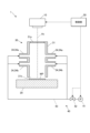
- FIG. 1 is a schematic diagram of a laser processing apparatus according to an embodiment
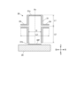
- FIG. 11 is a cross-sectional view of a hood according to a modified example of the embodiment.
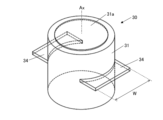
- FIG. 11 is a perspective view of a hood according to a modified example of the embodiment.
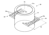
- FIG. 11 is a perspective view of a hood according to a modified example of the embodiment.
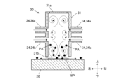
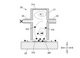
- FIG. 2 is a diagram showing a gas flow within a hood according to an embodiment.
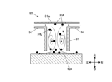
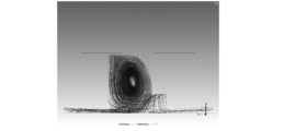
- FIG. 1 illustrates gas flow within a conventional hood.
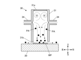
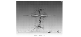
- FIG. 2 is a diagram showing a gas flow within a hood according to an embodiment.
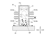
- FIG. 11 is a diagram showing a gas flow in a hood according to a modified example.
- FIG. 1 illustrates gas flow within a conventional hood.
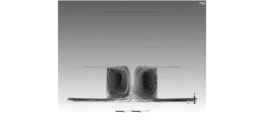
- FIG. 2 is a diagram showing a gas flow within a hood according to an embodiment.
- FIG. 11 is a diagram showing a gas flow in a hood according to a modified example.
- FIG. 11 is a diagram showing a gas flow within a hood according to a modified example of the embodiment.
- FIG. 11 is a diagram showing a gas flow within a hood according to a modified example of the embodiment.
- FIG. FIG. FIG. FIG. FIG. FIG. FIG. FIG. FIG. FIG. FIG. FIG. 11 is a cross-sectional view of a hood according to a modified example of the embodiment.
- FIG. 11 is a cross-sectional view of a hood according to a modified example of the embodiment.
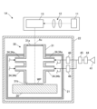
- FIG. 13 is a diagram showing a laser processing apparatus according to a modified example of the embodiment.
- FIG. 1 is a schematic diagram of a laser processing device 1 according to the present embodiment.
- the laser processing apparatus 1 irradiates a workpiece WP, which is an object to be processed, with a laser to perform processing such as annealing, welding, etc.
- the material of the workpiece WP is not particularly limited, but is, for example, silicon, silicon carbide, etc.
- the laser processing apparatus 1 includes a laser irradiation unit 10 , a support table (stage) 20 , a hood 30 , a gas supply unit 40 , and a control unit 50 .
- the laser irradiation unit 10 includes a laser oscillator and an optical system (not shown).
- the laser irradiation unit 10 irradiates a predetermined laser beam downward according to the type of processing.
- the support table 20 is disposed below the laser irradiation unit 10 and supports the workpiece WP on its upper surface. At least one of the laser irradiation unit 10 and the support table 20 may have a movable part so that the laser irradiation position on the workpiece WP can be adjusted.
- the hood 30 is disposed below the laser irradiation unit 10 and above the support table 20, and covers the workpiece WP placed on the support table 20.
- a predetermined gas is supplied into the hood 30 from a gas supply unit 40.
- the hood 30 exposes the workpiece WP to a predetermined gas atmosphere while allowing the laser from the laser irradiation unit 10 above to pass through.
- the specific configuration of the hood 30 will be described later.
- the gas supply unit 40 supplies (applies) a specified gas into the hood 30.
- the gas supplied may be, for example, an inert gas such as nitrogen or oxygen.
- the gas supply unit 40 has a gas source 41, which is a gas pump or a gas cylinder, a valve 42, and piping 43 that connects the gas source 41 to the hood 30 (each nozzle 34) via the valve 42.
- the control unit 50 is configured, for example, by a CPU (Central Processing Unit) and controls each part of the laser processing device 1. Specifically, the control unit 50 controls the operation of the laser irradiation unit 10 to irradiate the laser, and controls the operation of the valve 42 and gas source 41 of the gas supply unit 40 to supply a specified gas to the hood 30. Each part of the gas supply unit 40 may be manually controlled.
- a CPU Central Processing Unit
- the hood 30 includes a cylindrical portion 31 and a nozzle 34 .
- the tubular portion 31 is formed in a cylindrical shape having a central axis Ax along the up-down direction.
- the shape of the tubular portion 31 is not limited to a cylindrical shape as long as it is cylindrical.
- the direction along the central axis Ax may be referred to as the “axial direction,” and the direction perpendicular to the axial direction may be referred to as the “radial direction.”
- the direction in which the nozzle 34 is erected in the hood 30 (the left-right direction on the paper in FIG. 1, etc.) may be referred to as the “left-right (direction).”
- the upper end (one end) of the cylindrical portion 31 is closed and has a protective glass 31a (transmitting portion) that transmits a laser.
- the protective glass 31a is provided over substantially the entire upper end surface of the cylindrical portion 31.
- the protective glass 31a transmits most of the laser irradiated from the laser irradiation unit 10 above into the hood 30 (cylindrical portion 31).
- the protective glass 31a prevents dust PA such as fine particles (see FIGS. 4A, 4B, etc.) generated from the workpiece WP by laser processing from adhering to the optical system of the laser irradiation unit 10.
- the lower end (the other end) of the cylindrical portion 31 is an opening 31b that is open on the entire surface.
- the opening 31b faces the upper surface of the support base 20 in the vertical direction with a predetermined gap interposed between the opening 31b and the upper surface of the support base 20.
- the nozzle 34 is provided on the outer circumferential surface of the cylindrical portion 31 and blows gas into the inside of the cylindrical portion 31 .
- a total of four nozzles 34 are provided, with two (two sets) of nozzles arranged side by side in the axial direction, two of which form a pair on the left and right sides of the radial direction of the cylindrical portion 31. That is, one set (two nozzles) of nozzles 34a is provided on the upper side, and one set (two nozzles) of nozzles 34b is provided on the lower side.
- the nozzles 34 are arranged in parallel in the radial direction.
- the number and basic arrangement of the nozzles 34 are not particularly limited as long as they include the nozzles 34 arranged in the center of the axial direction, which will be described later.
- the nozzles 34 may be provided on only one side that does not form a pair in the radial direction (i.e., an odd number), or one or more pairs may be provided, or the two nozzles located on opposite sides in the radial direction may not face each other (their axial positions may be different).
- the two nozzles 34 facing each other on the left and right may not be symmetrical or axially symmetrical with each other.
- each nozzle 34 may be divided into a plurality of nozzles in the width direction (see FIG. 3B).
- the two nozzles 34 may face each other in a plane perpendicular to the axial direction of the cylindrical portion 31, and may not be aligned along the radial direction.
- each nozzle 34 is the center of the cylindrical portion 31.
- the "center” in the axial direction refers to a portion of the cylindrical portion 31 excluding the upper and lower ends. In other words, it is sufficient that each nozzle 34 is spaced apart from the upper and lower ends of the cylindrical portion 31.
- each nozzle 34 is disposed at an axial position defined by the following first length L1 and second length L2.
- the first length L1 is the axial length from the upper end (one end) of the cylindrical portion 31 to the nozzle 34
- the second length L2 is the axial length from the lower end (the other end) of the cylindrical portion 31 to the nozzle 34.
- the first length L1 and the second length L2 may be any length other than zero. For ease of understanding, FIG.
- the "axial position of the nozzle 34" refers to the center position of the portion of the nozzle 34 that opens into the inner diameter of the cylindrical portion 31.
- the first length L1 may be the distance from the upper end of the inner diameter (hole) of the nozzle 34
- the second length L2 may be the distance from the lower end of the inner diameter of the nozzle 34.
- a first axial length L1 from the upper end of the cylindrical portion 31 to each nozzle 34 satisfies the following formula (3).
- D is the inner diameter of the tubular portion 31.
- D may be, for example, an equivalent diameter (the diameter of the cylindrical tubular portion 31 having the same cross-sectional area) or may be the minimum or maximum width of the cross section perpendicular to the axial direction.
- the first length L1 is preferably equal to or greater than 50 mm.
- a second axial length L2 from the lower end of the cylindrical portion 31 to each nozzle 34 satisfies the following formula (4).
- the second length L2 is preferably equal to or greater than 50 mm. More preferably, the second length L2 satisfies the following formula (7). L2 ⁇ 0.5D (7)
- FIGS. 3A and 3B illustrate a hood 30 in which only one set of nozzles 34 is provided in the axial direction.
- the "width W of the nozzle 34” refers to the length along a direction perpendicular to the axial direction of the portion of the nozzle 34 that opens into the inner diameter (hole) of the cylindrical portion 31.
- the center of the nozzle 34 in the width direction does not have to coincide with the center of the cylindrical portion 31 in the same direction (i.e., the central axis Ax).
- the nozzle 34 may be composed of a plurality of partial nozzles 34c arranged in parallel in the width direction.
- the nozzles 34 may include nozzles that are not radially arranged with respect to the central axis Ax of the cylindrical portion 31 when viewed in the axial direction.
- the nozzles 34 may be inclined obliquely with respect to the axial direction. In this case, the two nozzles 34 in a pair, left and right, may face in different oblique directions (for example, obliquely upward and obliquely downward).
- the axial length (thickness) of the inner diameter (hole) of the nozzle 34 is not particularly limited, but is preferably sufficiently small relative to the axial height of the cylindrical portion 31 .
- the length of the inner diameter (hole portion) of the nozzle 34 along the gas flow perpendicular to the width direction is not particularly limited, but it is preferable that the nozzle 34 has a predetermined run-up length so that a uniform flow is formed in the width direction to a certain extent within the nozzle 34.
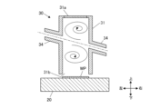
- each nozzle 34 of the hood 30 is disposed in the axial center of the cylindrical portion 31. Therefore, as shown in FIG. 4A, multiple layers of vortex gas flows are formed in the axial direction within the cylindrical portion 31.
- the control unit 50 drives the laser irradiation unit 10 to irradiate a laser beam downward from the laser irradiation unit 10.
- This laser beam passes through the protective glass 31a of the hood 30 and is irradiated into the cylindrical portion 31, and performs a predetermined laser processing on the workpiece WP placed in the opening 31b.
- At least the hood 30 and the support base 20 are housed in a chamber (not shown), and gas leaking from the opening 31b of the hood 30 is sealed in the chamber. The gas in the chamber is exhausted to the outside through an exhaust line connected to the chamber.
- the workpiece WP is processed by the laser in a state in which multiple layers of gas flow are formed in the axial direction inside the hood 30 (cylindrical portion 31).
- dust PA generated from the workpiece WP was stirred up by the gas flow and sometimes adhered to the protective glass 81a at the upper end of the hood 80.
- the dust PA adhered to the protective glass 81a attenuates the laser that passes through the protective glass 81a.
- the upper gas flow can prevent the dust PA from approaching the protective glass 31a. This makes it possible to prevent the dust PA from adhering to the protective glass 31a, and therefore to suppress laser attenuation.
- the gas supply amounts may be different between the opposing left and right nozzles 34. Even in this case, even if the balance of the gas flows between the left and right is lost, at least two layers of gas flows can be formed in the axial direction.
- Fig. 5B only one set of nozzles 34 may be provided. In this case, the gas flow downward does not have to be vortex-shaped, as shown in Fig. 6A. Also, as shown in Fig. 6B, even when there is only one set of nozzles 34, the gas supply amounts may be different between the left and right nozzles 34.
- the nozzle 34 of the hood 30 is disposed in the axial center portion of the cylindrical portion 31.
- the nozzle 34 is disposed in an axial position spaced apart from the upper and lower ends of the cylindrical portion 31. Therefore, the gas supplied from the nozzle 34 forms at least two layers of gas flow in the axial direction inside the cylindrical portion 31. This makes it possible to suppress adhesion of the dust PA to the protective glass 31a, and therefore makes it possible to suppress attenuation of the laser.
- the nozzles 34 are disposed in a portion of the circumferential direction of the cylindrical portion 31. In other words, the nozzles 34 are not formed over the entire circumference of the cylindrical portion 31. Therefore, gas is likely to escape vertically in the inner portion of the circumferential surface of the cylindrical portion 31 where the nozzles 34 are not formed. This makes it possible to favorably form vertical vortices that swirl in the vertical direction.
- the first axial length L1 from the upper end of the cylindrical portion 31 to the nozzle 34 satisfies the above-mentioned formula (3), so that a gas flow above the nozzle 34 can be more reliably formed. Therefore, adhesion of dust PA to the protective glass 31a can be more reliably suppressed.
- the second axial length L2 from the lower end of the cylindrical portion 31 to the nozzle 34 satisfies the above-mentioned formula (4), so that a gas flow below the nozzle 34 can be more reliably formed. Therefore, adhesion of dust PA to the protective glass 31a can be more reliably suppressed.
- the width W of the nozzle along the direction perpendicular to the axial direction satisfies the above-mentioned formula (5), so at least two layers of gas flow in the axial direction can be suitably formed in the width direction within the cylindrical portion 31. Therefore, adhesion of dust PA to the protective glass 31a can be more reliably suppressed.
- the nozzles 34 include a pair of nozzles facing each other in a plane perpendicular to the axial direction. This allows the gas flows to collide in a plane perpendicular to the axial direction, and effectively forms vertical vortices that swirl in the vertical direction.
- the nozzles 34 do not have to be arranged radially with respect to the central axis Ax of the cylindrical portion 31 when viewed from the axial direction. Even if the nozzles 34 are not arranged radially, vertical vortices that swirl in the vertical direction can be formed.
- each part of the analysis model is as follows: Hood shape Total height: 258mm Inner diameter D: 160 mm First length L1: 103 mm Axial distance between upper and lower nozzles: 54 mm Axial height of each nozzle inlet: 2 mm Nozzle width W: 136 mm Left-right distance L3 between the ends of the two nozzles (see FIG.
- the first length L1 and the axial distance between the upper and lower nozzles are the lengths to the blowing ports (holes) of each nozzle.
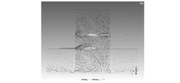
- Figures 7A to 10C show contour diagrams of the analysis results.
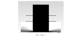
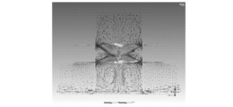
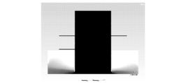
- Figures 7A to 7C show model 1
- Figures 8A to 8C show model 2
- Figures 9A to 9C show model 3
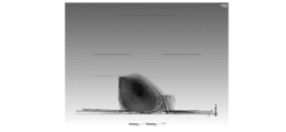
- Figures 10A to 10C show the analysis results for a conventional hood 80.
- (a) shows the path line from the bottom of the hood (e.g., at a height of 50 mm)
- (b) shows the gas (e.g., nitrogen) concentration distribution
- (c) is a velocity vector diagram.
- the top and bottom and left and right of the paper correspond to the top and bottom and left and right of the hood.
- Model 1 hood 30 without the lower nozzle set.
- the gas flow forms a vortex below the nozzle 34, so that the dust PA below the hood 30 has difficulty reaching the protective glass 31a.
- the gas concentration inside the hood 30 is generally high. Two layers of vortex gas flows are formed above and below the nozzle 34 .
- Model 2 equal gas amount balance between the left and right.
- the gas flow forms a vortex below the lower nozzle 34b, and the dust PA below the hood 30 has difficulty reaching the protective glass 31a or the upper nozzle 34a.
- the gas concentration inside the hood 30 is generally high. Three layers of vortex gas flows are formed above and below the upper nozzles 34a, below the lower nozzles 34b, and between the two sets of nozzles 34, one above the other.
- Model 3 uneven gas volume balance between the left and right.
- the gas flow forms a vortex below the lower nozzle 34b, and the dust PA below the hood 30 has difficulty reaching the protective glass 31a or the upper nozzle 34a.
- the gas inside the hood 30 exits from the side where the lower nozzle 34b is blowing more strongly. ⁇ Three layers of vortex gas flow are formed above and below.
- the gas flow is a vortex flow with only one layer above and below, and there is a risk that the dust PA at the bottom of the hood 30 will be sucked up onto the protective glass 31a.
- the gas concentration inside the hood 30 is generally high.
- Models 1 to 3 which have three gas layers above and below, are expected to be more effective in preventing the adhesion of dust PA than Model 1, which has two gas layers above and below.
- Model 1 unlike Models 2 and 3, there is a risk that the dust PA is not being discharged properly.
- Gas purging inside the hood 30 is performed appropriately in all of models 1 to 3.
- the main gas application combinations that can be expected to prevent the adhesion of dust PA are shown in Table 2 below. As shown in Table 2, it is preferable that at least one of the upper nozzles 34a applies gas at a "strong" level. Of the combinations in Table 2, No. 1 and No. 2 provided the most desirable results. It is believed that the same effect can be obtained even if the difference in gas application between the left and right sides of each nozzle set is reversed. In addition, when three or more nozzle sets are provided, the pattern of the third and subsequent sets affects the magnitude of the dust PA adhesion prevention effect, but does not affect the presence or absence of said effect.
- the present invention is not limited to the above embodiment.
- the laser is irradiated along the axial direction of the hood 30, but the laser may be inclined with respect to the axial direction.
- a regulator 44 adjusts the blowing pressure from a gas source 41 such as a cylinder.
- the opening/closing valve 45 switches blowing ON/OFF.
- the flow rate control valves 46 are disposed at the upper and lower stages, and adjust the flow rate of the blown gas separately for the upper and lower stages.
- a laser beam emitted from a laser oscillator 11 is passed through an optical system 12 to have its shape and output adjusted, and then the laser irradiation position is controlled by a galvano scanner 13.
- the hood 30 is fixed to a chamber 21 arranged in an enclosure 22.
- the support table (stage) 20 on which the workpiece WP is placed is position-controlled and positioned relative to the hood 30 during processing. At this time, the axial gap between the lower end of the hood 30 and the upper surface of the support table 20 is set to a very short distance (about 2 mm in an actual machine).
- each of the above components is controlled by a control unit 50 (see FIG. 1).
- the laser processing apparatus according to the present invention can be widely applied to laser processing of a workpiece in a gas atmosphere, regardless of the type of processing or the material of the workpiece.
- the details shown in the above embodiment can be modified as appropriate without departing from the spirit of the invention.
- the present invention is useful for suppressing laser attenuation.
- Laser processing device 10 Laser irradiation unit (laser irradiation means) 20 Support stand 30 Hood (laser device hood) 31 Cylindrical portion 31a Protective glass (transmitting portion) 31b Opening 34 Nozzle 34a Upper nozzle 34b Lower nozzle 34c Partial nozzle 40 Gas supply unit (gas supply means) 41 Gas source 42 Valve 43 Pipe 50 Control unit 80 Conventional hood 81 Conventional cylindrical portion 81a Conventional protective glass 84 Conventional nozzle Ax Central axis D Inner diameter PA Particle W Width WP Workpiece
Landscapes
- Engineering & Computer Science (AREA)
- Physics & Mathematics (AREA)
- Optics & Photonics (AREA)
- Plasma & Fusion (AREA)
- Mechanical Engineering (AREA)
- Laser Beam Processing (AREA)
Abstract
Priority Applications (5)
| Application Number | Priority Date | Filing Date | Title |
|---|---|---|---|
| JP2025527901A JPWO2024257710A1 (fr) | 2023-06-12 | 2024-06-10 | |
| KR1020257025883A KR20260022920A (ko) | 2023-06-12 | 2024-06-10 | 레이저장치용 후드, 레이저가공장치 및 레이저가공방법 |
| CN202480009620.3A CN120659689A (zh) | 2023-06-12 | 2024-06-10 | 用于激光装置的罩、激光加工装置及激光加工方法 |
| EP24823326.4A EP4681861A4 (fr) | 2023-06-12 | 2024-06-10 | Capot pour dispositif laser, dispositif de traitement laser et procédé de traitement laser |
| US19/342,721 US20260027651A1 (en) | 2023-06-12 | 2025-09-29 | Hood for laser device, laser processing device, and laser processing method |
Applications Claiming Priority (2)
| Application Number | Priority Date | Filing Date | Title |
|---|---|---|---|
| JP2023-096283 | 2023-06-12 | ||
| JP2023096283 | 2023-06-12 |
Related Child Applications (1)
| Application Number | Title | Priority Date | Filing Date |
|---|---|---|---|
| US19/342,721 Continuation US20260027651A1 (en) | 2023-06-12 | 2025-09-29 | Hood for laser device, laser processing device, and laser processing method |
Publications (1)
| Publication Number | Publication Date |
|---|---|
| WO2024257710A1 true WO2024257710A1 (fr) | 2024-12-19 |
Family
ID=93852106
Family Applications (1)
| Application Number | Title | Priority Date | Filing Date |
|---|---|---|---|
| PCT/JP2024/020968 Ceased WO2024257710A1 (fr) | 2023-06-12 | 2024-06-10 | Capot pour dispositif laser, dispositif de traitement laser et procédé de traitement laser |
Country Status (6)
| Country | Link |
|---|---|
| US (1) | US20260027651A1 (fr) |
| EP (1) | EP4681861A4 (fr) |
| JP (1) | JPWO2024257710A1 (fr) |
| KR (1) | KR20260022920A (fr) |
| CN (1) | CN120659689A (fr) |
| WO (1) | WO2024257710A1 (fr) |
Citations (7)
| Publication number | Priority date | Publication date | Assignee | Title |
|---|---|---|---|---|
| JPS509680Y1 (fr) * | 1969-07-30 | 1975-03-25 | ||
| JPH0929465A (ja) * | 1995-07-21 | 1997-02-04 | Ricoh Co Ltd | レーザ加工装置 |
| JPH09164495A (ja) * | 1995-12-18 | 1997-06-24 | Mitsubishi Electric Corp | レーザ加工ヘッド |
| WO2003076117A1 (fr) * | 2002-03-14 | 2003-09-18 | Hitachi Zosen Corporation | Procede et dispositif empechant des impuretes et autres substances contaminantes d'adherer a des composants optiques d'une machine a faisceau laser |
| JP2004268080A (ja) * | 2003-03-07 | 2004-09-30 | Sumitomo Heavy Ind Ltd | レーザ加工装置および加工方法 |
| JP2007144491A (ja) * | 2005-11-30 | 2007-06-14 | Kyocera Kinseki Corp | レーザ加工装置 |
| JP2022001372A (ja) | 2020-06-19 | 2022-01-06 | 株式会社フジクラ | レーザ加工用ヘッド及びレーザ加工装置 |
Family Cites Families (3)
| Publication number | Priority date | Publication date | Assignee | Title |
|---|---|---|---|---|
| CN203227932U (zh) * | 2013-05-17 | 2013-10-09 | 武汉梅曼科技有限公司 | 一种多层气帘型激光切割头 |
| US11103954B2 (en) * | 2016-05-30 | 2021-08-31 | Honda Motor Co., Ltd. | Laser processing device with tubular filter |
| JP6852572B2 (ja) * | 2017-06-01 | 2021-03-31 | トヨタ自動車株式会社 | レーザ溶接装置 |
-
2024
- 2024-06-10 KR KR1020257025883A patent/KR20260022920A/ko active Pending
- 2024-06-10 WO PCT/JP2024/020968 patent/WO2024257710A1/fr not_active Ceased
- 2024-06-10 EP EP24823326.4A patent/EP4681861A4/fr active Pending
- 2024-06-10 CN CN202480009620.3A patent/CN120659689A/zh active Pending
- 2024-06-10 JP JP2025527901A patent/JPWO2024257710A1/ja active Pending
-
2025
- 2025-09-29 US US19/342,721 patent/US20260027651A1/en active Pending
Patent Citations (7)
| Publication number | Priority date | Publication date | Assignee | Title |
|---|---|---|---|---|
| JPS509680Y1 (fr) * | 1969-07-30 | 1975-03-25 | ||
| JPH0929465A (ja) * | 1995-07-21 | 1997-02-04 | Ricoh Co Ltd | レーザ加工装置 |
| JPH09164495A (ja) * | 1995-12-18 | 1997-06-24 | Mitsubishi Electric Corp | レーザ加工ヘッド |
| WO2003076117A1 (fr) * | 2002-03-14 | 2003-09-18 | Hitachi Zosen Corporation | Procede et dispositif empechant des impuretes et autres substances contaminantes d'adherer a des composants optiques d'une machine a faisceau laser |
| JP2004268080A (ja) * | 2003-03-07 | 2004-09-30 | Sumitomo Heavy Ind Ltd | レーザ加工装置および加工方法 |
| JP2007144491A (ja) * | 2005-11-30 | 2007-06-14 | Kyocera Kinseki Corp | レーザ加工装置 |
| JP2022001372A (ja) | 2020-06-19 | 2022-01-06 | 株式会社フジクラ | レーザ加工用ヘッド及びレーザ加工装置 |
Non-Patent Citations (1)
| Title |
|---|
| See also references of EP4681861A1 |
Also Published As
| Publication number | Publication date |
|---|---|
| CN120659689A (zh) | 2025-09-16 |
| KR20260022920A (ko) | 2026-02-20 |
| JPWO2024257710A1 (fr) | 2024-12-19 |
| US20260027651A1 (en) | 2026-01-29 |
| EP4681861A4 (fr) | 2026-07-22 |
| EP4681861A1 (fr) | 2026-01-21 |
Similar Documents
| Publication | Publication Date | Title |
|---|---|---|
| US6926801B2 (en) | Laser machining method and apparatus | |
| CN113165116B (zh) | 激光焊接装置 | |
| CN1328003C (zh) | 激光加工装置 | |
| JP7224911B2 (ja) | ガラスウェブを加工する方法 | |
| CN111496378B (zh) | 焊接装置以及焊接方法 | |
| JP6167055B2 (ja) | レーザノズル、レーザ加工装置、及びレーザ加工方法 | |
| KR101302927B1 (ko) | 표면 처리 장치 | |
| CA2698835A1 (fr) | Tuyere de traitement laser | |
| CN108349044A (zh) | 激光处理装置整流装置及激光处理装置 | |
| CN107106938A (zh) | 流体处理结构、光刻设备和器件制造方法 | |
| WO2017034979A1 (fr) | Procédés et appareil pour le traitement du verre | |
| CN116061436B (zh) | 层叠造型装置及吹出喷嘴 | |
| KR102092712B1 (ko) | 레이저 처리 장치 및 방법 | |
| WO2017034975A1 (fr) | Procédés et appareil de traitement du verre | |
| JP3525841B2 (ja) | レーザリペア方法および装置 | |
| TW201811478A (zh) | 雷射加工裝置及雷射加工排屑裝置 | |
| CZ20023623A3 (cs) | Způsob a zařízení pro ochranu laserového opracovacího zařízení proti prachu | |
| JPH116086A (ja) | レーザ光を用いた表面不要物除去装置 | |
| US20260027651A1 (en) | Hood for laser device, laser processing device, and laser processing method | |
| JPH10280152A (ja) | チャンバレスレーザcvd装置 | |
| EP1432014A2 (fr) | Procédé et appareil de rinçage et pompage d'une chambre à vide | |
| KR20200089398A (ko) | 레이저 처리 장치 및 방법 | |
| JP7514796B2 (ja) | 真空レーザ加工装置 | |
| US20130032030A1 (en) | Exhaust air system and method therefor | |
| JP7332596B2 (ja) | 基板の局所表面領域を処理する処理ヘッド、処理システム、および処理方法 |
Legal Events
| Date | Code | Title | Description |
|---|---|---|---|
| 121 | Ep: the epo has been informed by wipo that ep was designated in this application |
Ref document number: 24823326 Country of ref document: EP Kind code of ref document: A1 |
|
| WWE | Wipo information: entry into national phase |
Ref document number: 202480009620.3 Country of ref document: CN |
|
| WWP | Wipo information: published in national office |
Ref document number: 202480009620.3 Country of ref document: CN |
|
| ENP | Entry into the national phase |
Ref document number: 2025527901 Country of ref document: JP Kind code of ref document: A |
|
| WWE | Wipo information: entry into national phase |
Ref document number: 2025527901 Country of ref document: JP |
|
| WWE | Wipo information: entry into national phase |
Ref document number: 2024823326 Country of ref document: EP |
|
| ENP | Entry into the national phase |
Ref document number: 2024823326 Country of ref document: EP Effective date: 20251016 |
|
| ENP | Entry into the national phase |
Ref document number: 2024823326 Country of ref document: EP Effective date: 20251016 |
|
| ENP | Entry into the national phase |
Ref document number: 2024823326 Country of ref document: EP Effective date: 20251016 |
|
| ENP | Entry into the national phase |
Ref document number: 2024823326 Country of ref document: EP Effective date: 20251016 |
|
| ENP | Entry into the national phase |
Ref document number: 2024823326 Country of ref document: EP Effective date: 20251016 |
|
| NENP | Non-entry into the national phase |
Ref country code: DE |